Embed Size (px)
Citation preview
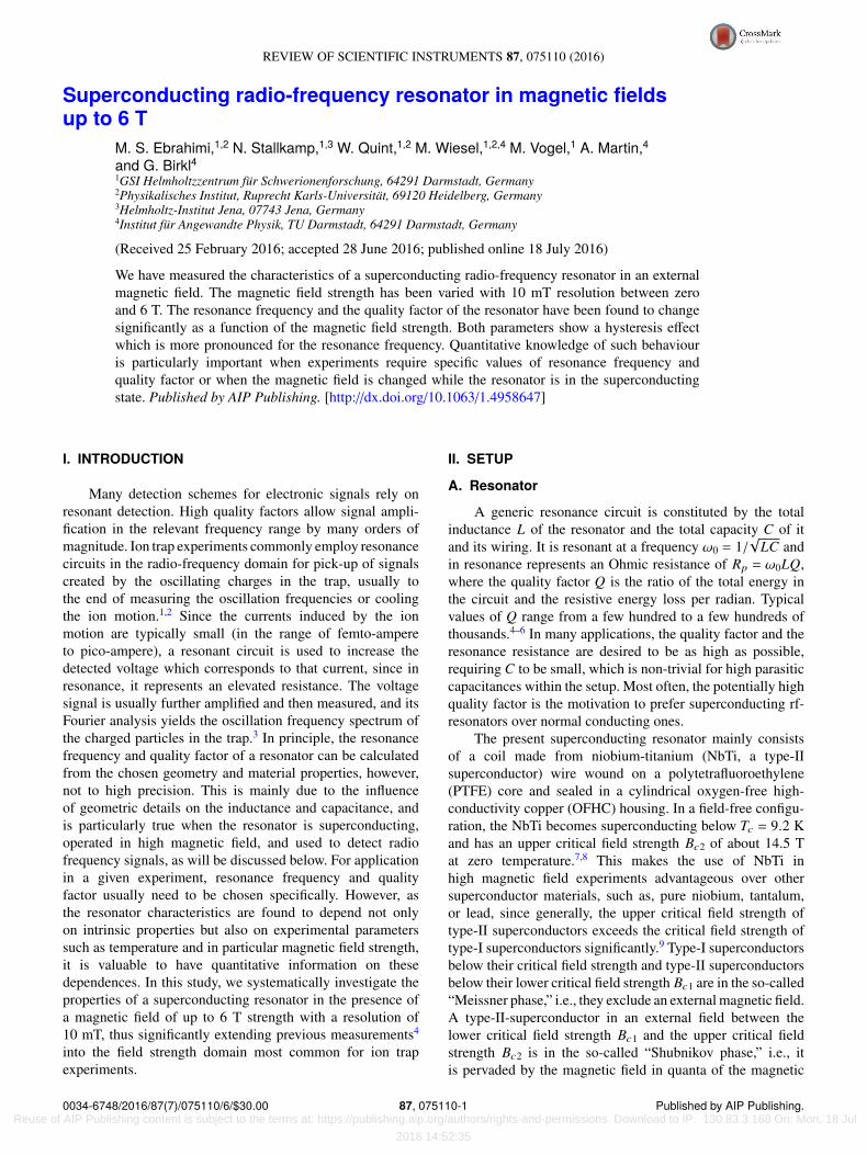
REVIEW OF SCIENTIFIC INSTRUMENTS 87, 075110 (2016)
Superconducting radio-frequency resonator in magnetic fieldsup to 6 T
M. S. Ebrahimi,1,2 N. Stallkamp,1,3 W. Quint,1,2 M. Wiesel,1,2,4 M. Vogel,1 A. Martin,4and G. Birkl41GSI Helmholtzzentrum für Schwerionenforschung, 64291 Darmstadt, Germany2Physikalisches Institut, Ruprecht Karls-Universität, 69120 Heidelberg, Germany3Helmholtz-Institut Jena, 07743 Jena, Germany4Institut für Angewandte Physik, TU Darmstadt, 64291 Darmstadt, Germany
(Received 25 February 2016; accepted 28 June 2016; published online 18 July 2016)
We have measured the characteristics of a superconducting radio-frequency resonator in an externalmagnetic field. The magnetic field strength has been varied with 10 mT resolution between zeroand 6 T. The resonance frequency and the quality factor of the resonator have been found to changesignificantly as a function of the magnetic field strength. Both parameters show a hysteresis effectwhich is more pronounced for the resonance frequency. Quantitative knowledge of such behaviouris particularly important when experiments require specific values of resonance frequency andquality factor or when the magnetic field is changed while the resonator is in the superconductingstate. Published by AIP Publishing. [http://dx.doi.org/10.1063/1.4958647]
I. INTRODUCTION
Many detection schemes for electronic signals rely onresonant detection. High quality factors allow signal ampli-fication in the relevant frequency range by many orders ofmagnitude. Ion trap experiments commonly employ resonancecircuits in the radio-frequency domain for pick-up of signalscreated by the oscillating charges in the trap, usually tothe end of measuring the oscillation frequencies or coolingthe ion motion.1,2 Since the currents induced by the ionmotion are typically small (in the range of femto-ampereto pico-ampere), a resonant circuit is used to increase thedetected voltage which corresponds to that current, since inresonance, it represents an elevated resistance. The voltagesignal is usually further amplified and then measured, and itsFourier analysis yields the oscillation frequency spectrum ofthe charged particles in the trap.3 In principle, the resonancefrequency and quality factor of a resonator can be calculatedfrom the chosen geometry and material properties, however,not to high precision. This is mainly due to the influenceof geometric details on the inductance and capacitance, andis particularly true when the resonator is superconducting,operated in high magnetic field, and used to detect radiofrequency signals, as will be discussed below. For applicationin a given experiment, resonance frequency and qualityfactor usually need to be chosen specifically. However, asthe resonator characteristics are found to depend not onlyon intrinsic properties but also on experimental parameterssuch as temperature and in particular magnetic field strength,it is valuable to have quantitative information on thesedependences. In this study, we systematically investigate theproperties of a superconducting resonator in the presence ofa magnetic field of up to 6 T strength with a resolution of10 mT, thus significantly extending previous measurements4
into the field strength domain most common for ion trapexperiments.
II. SETUP
A. Resonator
A generic resonance circuit is constituted by the totalinductance L of the resonator and the total capacity C of itand its wiring. It is resonant at a frequency ω0 = 1/
√LC and
in resonance represents an Ohmic resistance of Rp = ω0LQ,where the quality factor Q is the ratio of the total energy inthe circuit and the resistive energy loss per radian. Typicalvalues of Q range from a few hundred to a few hundreds ofthousands.4–6 In many applications, the quality factor and theresonance resistance are desired to be as high as possible,requiring C to be small, which is non-trivial for high parasiticcapacitances within the setup. Most often, the potentially highquality factor is the motivation to prefer superconducting rf-resonators over normal conducting ones.
The present superconducting resonator mainly consistsof a coil made from niobium-titanium (NbTi, a type-IIsuperconductor) wire wound on a polytetrafluoroethylene(PTFE) core and sealed in a cylindrical oxygen-free high-conductivity copper (OFHC) housing. In a field-free configu-ration, the NbTi becomes superconducting below Tc = 9.2 Kand has an upper critical field strength Bc2 of about 14.5 Tat zero temperature.7,8 This makes the use of NbTi inhigh magnetic field experiments advantageous over othersuperconductor materials, such as, pure niobium, tantalum,or lead, since generally, the upper critical field strength oftype-II superconductors exceeds the critical field strength oftype-I superconductors significantly.9 Type-I superconductorsbelow their critical field strength and type-II superconductorsbelow their lower critical field strength Bc1 are in the so-called“Meissner phase,” i.e., they exclude an external magnetic field.A type-II-superconductor in an external field between thelower critical field strength Bc1 and the upper critical fieldstrength Bc2 is in the so-called “Shubnikov phase,” i.e., itis pervaded by the magnetic field in quanta of the magnetic
0034-6748/2016/87(7)/075110/6/$30.00 87, 075110-1 Published by AIP Publishing. Reuse of AIP Publishing content is subject to the terms at: https://publishing.aip.org/authors/rights-and-permissions. Download to IP: 130.83.3.168 On: Mon, 18 Jul
2016 14:52:35
075110-2 Ebrahimi et al. Rev. Sci. Instrum. 87, 075110 (2016)
fluxΦ0 = h/(2e) ≈ 2.067 · 10−15 Tm2, which create vortices inthe superconductor. These are circular super-currents aroundnormal-conducting cores which form about the magnetic fieldlines.8 The local inhomogeneities in the lattice structure ofthe superconducting material lead to a localization of vortices,which is commonly known as vortex pinning.9 In the presenceof an ac-current such as the present radio-frequency signal,the interaction of the vortices with the current gives rise toan effective resistance which leads to signal loss. This meansthat the energy loss per oscillation is non-zero even for sucha superconductor, as has been detailed for example in Ref. 9.The loss scales with the third power of the frequency, such thatthe use of a type-II superconducting resonator is advantageousover a normal-conducting resonator only for sufficiently smallfrequencies, typically on the scale of few tens of MHz andbelow, which however includes most of the range of ionoscillation frequencies common to ion trap experiments.
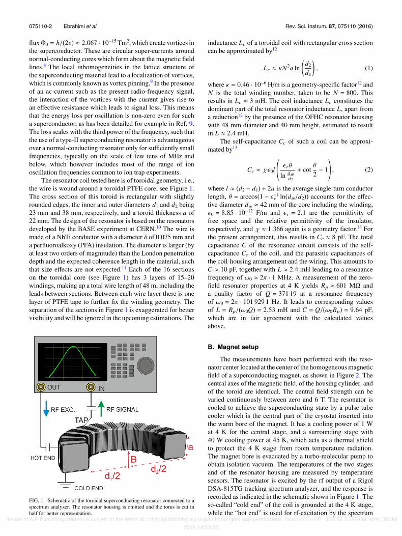
The resonator coil tested here is of toroidal geometry, i.e.,the wire is wound around a toroidal PTFE core, see Figure 1.The cross section of this toroid is rectangular with slightlyrounded edges, the inner and outer diameters d1 and d2 being23 mm and 38 mm, respectively, and a toroid thickness a of22 mm. The design of the resonator is based on the resonatorsdeveloped by the BASE experiment at CERN.10 The wire ismade of a NbTi conductor with a diameter δ of 0.075 mm anda perfluoroalkoxy (PFA) insulation. The diameter is larger (byat least two orders of magnitude) than the London penetrationdepth and the expected coherence length in the material, suchthat size effects are not expected.11 Each of the 16 sectionson the toroidal core (see Figure 1) has 3 layers of 15–20windings, making up a total wire length of 48 m, including theleads between sections. Between each wire layer there is onelayer of PTFE tape to further fix the winding geometry. Theseparation of the sections in Figure 1 is exaggerated for bettervisibility and will be ignored in the upcoming estimations. The
FIG. 1. Schematic of the toroidal superconducting resonator connected to aspectrum analyzer. The resonator housing is omitted and the torus is cut inhalf for better representation.
inductance Lc of a toroidal coil with rectangular cross sectioncan be approximated by12
Lc ≈ κN2a ln(
d2
d1
), (1)
where κ = 0.46 · 10−6 H/m is a geometry-specific factor12 andN is the total winding number, taken to be N = 800. Thisresults in Lc ≈ 3 mH. The coil inductance Lc constitutes thedominant part of the total resonator inductance L, apart froma reduction12 by the presence of the OFHC resonator housingwith 48 mm diameter and 40 mm height, estimated to resultin L ≈ 2.4 mH.
The self-capacitance Cc of such a coil can be approxi-mated by13
Cc ≈ χϵ0l*.,
ϵ rθ
ln dwd2
+ cotθ
2− 1+/
-, (2)
where l ≈ (d2 − d1) + 2a is the average single-turn conductorlength, θ = arccos(1 − ϵ−1
r ln(dw/d2)) accounts for the effec-tive diameter dw ≈ 42 mm of the core including the winding,ϵ0 = 8.85 · 10−12 F/m and ϵ r = 2.1 are the permittivity offree space and the relative permittivity of the insulator,respectively, and χ ≈ 1.366 again is a geometry factor.13 Forthe present arrangement, this results in Cc ≈ 8 pF. The totalcapacitance C of the resonance circuit consists of the self-capacitance Cc of the coil, and the parasitic capacitances ofthe coil-housing arrangement and the wiring. This amounts toC ≈ 10 pF, together with L ≈ 2.4 mH leading to a resonancefrequency of ω0 ≈ 2π · 1 MHz. A measurement of the zero-field resonator properties at 4 K yields Rp ≈ 601 MΩ anda quality factor of Q = 371 19 at a resonance frequencyof ω0 = 2π · 101 929 1 Hz. It leads to corresponding valuesof L = Rp/(ω0Q) = 2.53 mH and C = Q/(ω0Rp) = 9.64 pF,which are in fair agreement with the calculated valuesabove.
B. Magnet setup
The measurements have been performed with the reso-nator center located at the center of the homogeneous magneticfield of a superconducting magnet, as shown in Figure 2. Thecentral axes of the magnetic field, of the housing cylinder, andof the toroid are identical. The central field strength can bevaried continuously between zero and 6 T. The resonator iscooled to achieve the superconducting state by a pulse tubecooler which is the central part of the cryostat inserted intothe warm bore of the magnet. It has a cooling power of 1 Wat 4 K for the central stage, and a surrounding stage with40 W cooling power at 45 K, which acts as a thermal shieldto protect the 4 K stage from room temperature radiation.The magnet bore is evacuated by a turbo-molecular pump toobtain isolation vacuum. The temperatures of the two stagesand of the resonator housing are measured by temperaturesensors. The resonator is excited by the rf output of a RigolDSA-815TG tracking spectrum analyzer, and the response isrecorded as indicated in the schematic shown in Figure 1. Theso-called “cold end” of the coil is grounded at the 4 K stage,while the “hot end” is used for rf-excitation by the spectrum
Reuse of AIP Publishing content is subject to the terms at: https://publishing.aip.org/authors/rights-and-permissions. Download to IP: 130.83.3.168 On: Mon, 18 Jul
2016 14:52:35

075110-3 Ebrahimi et al. Rev. Sci. Instrum. 87, 075110 (2016)
FIG. 2. Schematic overview of the measurement apparatus. The supercon-ducting magnet and heat shields have been cut open for better representation.
analyzer. The response of the system is measured by detectionof the signal as obtained from the “tap,” which is an electricalconnection attached to the coil between its ends. Both signals(excitation and response) are coupled capacitively through airto the hot end and analyzer, respectively, by bringing the endsof the respective conductors in close parallel proximity. Formeasurements without excitation, the readout is done directlythrough a small capacitance.
III. MEASUREMENTS
The resonator response measurements have been per-formed with the resonator being brought into the supercon-ducting state prior to introduction of the magnetic field (“zero-field cooling”). This situation is to be distinguished from thereverse order (“field cooling”) as the field penetration of thesuperconductor behaves differently, as discussed in Refs. 8and 9.
A. Spectral response
We have measured the spectral response of the resonatorcircuit upon tracking excitation for values of the magnetic fieldstrength between zero and 6 T with a resolution of 10 mT.Figure 3 shows response curves (signal strength as a functionof frequency) for 16 selected values of the magnetic fieldstrength in an upward scan of the B-field. Obviously, there is asignificant change in the spectral response with respect to theresonance frequency, the signal width (i.e., the quality factor),and the overall magnitude of the signal.
B. Resonance frequency
Figure 4 shows the resonance frequency as a functionof the magnetic field strength for all resonance curves of
FIG. 3. Measured resonator response as a function of the frequency forselected values of the magnetic field strength.
the upward scan. The overall trend is for the resonancefrequency to decrease monotonically with increasing magneticfield strength, particularly strongly between the smallest fieldvalues. The inset of Figure 4 shows an initial steep decreasefrom the field-free case to the point at 10 mT and a relativeflattening of the curve at about 120 mT. Overall, the resonancefrequency decreases from 101 929 0 Hz in the field-free caseto 101 912 9 Hz at B = 6 T, which is a relative change of1.5 · 10−4.
C. Quality factor
With increasing magnetic field, the quality factor Q(B)decreases, as seen by the broadening of the resonance. Toobtain the quality factor, the measured resonance curve isfitted with a Lorentz function, and the ratio of the resonancefrequency and the FWHM of the curve defines Q(B). Thehence measured value may somewhat underestimate the realquality factor due to the finite bandwidth β, but this is expected
FIG. 4. Measured resonance frequency as a function of the magnetic fieldstrength. Error bars are much smaller than the symbols. Inset: The first 25data points.
Reuse of AIP Publishing content is subject to the terms at: https://publishing.aip.org/authors/rights-and-permissions. Download to IP: 130.83.3.168 On: Mon, 18 Jul
2016 14:52:35
075110-4 Ebrahimi et al. Rev. Sci. Instrum. 87, 075110 (2016)
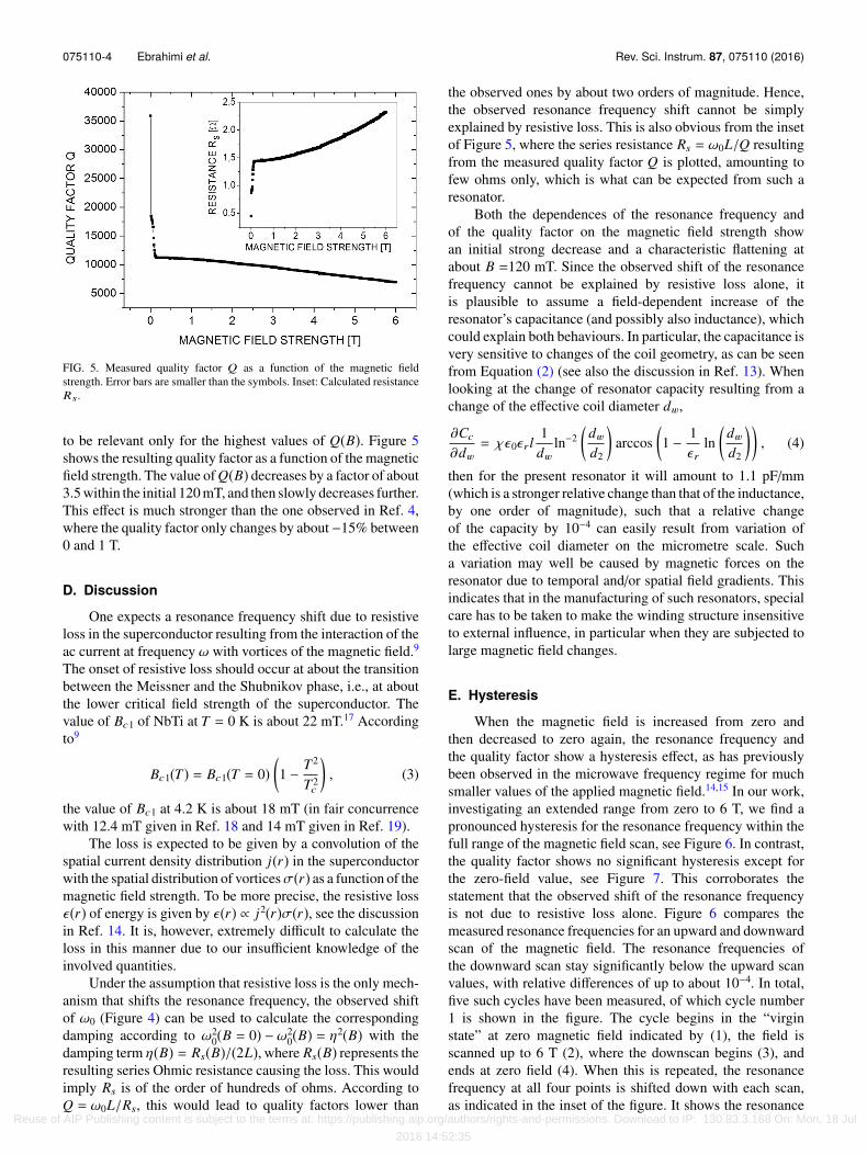
FIG. 5. Measured quality factor Q as a function of the magnetic fieldstrength. Error bars are smaller than the symbols. Inset: Calculated resistanceRs.
to be relevant only for the highest values of Q(B). Figure 5shows the resulting quality factor as a function of the magneticfield strength. The value of Q(B) decreases by a factor of about3.5 within the initial 120 mT, and then slowly decreases further.This effect is much stronger than the one observed in Ref. 4,where the quality factor only changes by about−15% between0 and 1 T.
D. Discussion
One expects a resonance frequency shift due to resistiveloss in the superconductor resulting from the interaction of theac current at frequency ω with vortices of the magnetic field.9
The onset of resistive loss should occur at about the transitionbetween the Meissner and the Shubnikov phase, i.e., at aboutthe lower critical field strength of the superconductor. Thevalue of Bc1 of NbTi at T = 0 K is about 22 mT.17 Accordingto9
Bc1(T) = Bc1(T = 0)(1 − T2
T2c
), (3)
the value of Bc1 at 4.2 K is about 18 mT (in fair concurrencewith 12.4 mT given in Ref. 18 and 14 mT given in Ref. 19).
The loss is expected to be given by a convolution of thespatial current density distribution j(r) in the superconductorwith the spatial distribution of vorticesσ(r) as a function of themagnetic field strength. To be more precise, the resistive lossϵ(r) of energy is given by ϵ(r) ∝ j2(r)σ(r), see the discussionin Ref. 14. It is, however, extremely difficult to calculate theloss in this manner due to our insufficient knowledge of theinvolved quantities.
Under the assumption that resistive loss is the only mech-anism that shifts the resonance frequency, the observed shiftof ω0 (Figure 4) can be used to calculate the correspondingdamping according to ω2
0(B = 0) − ω20(B) = η2(B) with the
damping term η(B) = Rs(B)/(2L), where Rs(B) represents theresulting series Ohmic resistance causing the loss. This wouldimply Rs is of the order of hundreds of ohms. According toQ = ω0L/Rs, this would lead to quality factors lower than
the observed ones by about two orders of magnitude. Hence,the observed resonance frequency shift cannot be simplyexplained by resistive loss. This is also obvious from the insetof Figure 5, where the series resistance Rs = ω0L/Q resultingfrom the measured quality factor Q is plotted, amounting tofew ohms only, which is what can be expected from such aresonator.
Both the dependences of the resonance frequency andof the quality factor on the magnetic field strength showan initial strong decrease and a characteristic flattening atabout B =120 mT. Since the observed shift of the resonancefrequency cannot be explained by resistive loss alone, itis plausible to assume a field-dependent increase of theresonator’s capacitance (and possibly also inductance), whichcould explain both behaviours. In particular, the capacitance isvery sensitive to changes of the coil geometry, as can be seenfrom Equation (2) (see also the discussion in Ref. 13). Whenlooking at the change of resonator capacity resulting from achange of the effective coil diameter dw,
∂Cc
∂dw= χϵ0ϵ rl
1dw
ln−2(
dw
d2
)arccos
(1 − 1
ϵ rln
(dw
d2
)), (4)
then for the present resonator it will amount to 1.1 pF/mm(which is a stronger relative change than that of the inductance,by one order of magnitude), such that a relative changeof the capacity by 10−4 can easily result from variation ofthe effective coil diameter on the micrometre scale. Sucha variation may well be caused by magnetic forces on theresonator due to temporal and/or spatial field gradients. Thisindicates that in the manufacturing of such resonators, specialcare has to be taken to make the winding structure insensitiveto external influence, in particular when they are subjected tolarge magnetic field changes.
E. Hysteresis
When the magnetic field is increased from zero andthen decreased to zero again, the resonance frequency andthe quality factor show a hysteresis effect, as has previouslybeen observed in the microwave frequency regime for muchsmaller values of the applied magnetic field.14,15 In our work,investigating an extended range from zero to 6 T, we find apronounced hysteresis for the resonance frequency within thefull range of the magnetic field scan, see Figure 6. In contrast,the quality factor shows no significant hysteresis except forthe zero-field value, see Figure 7. This corroborates thestatement that the observed shift of the resonance frequencyis not due to resistive loss alone. Figure 6 compares themeasured resonance frequencies for an upward and downwardscan of the magnetic field. The resonance frequencies ofthe downward scan stay significantly below the upward scanvalues, with relative differences of up to about 10−4. In total,five such cycles have been measured, of which cycle number1 is shown in the figure. The cycle begins in the “virginstate” at zero magnetic field indicated by (1), the field isscanned up to 6 T (2), where the downscan begins (3), andends at zero field (4). When this is repeated, the resonancefrequency at all four points is shifted down with each scan,as indicated in the inset of the figure. It shows the resonance
Reuse of AIP Publishing content is subject to the terms at: https://publishing.aip.org/authors/rights-and-permissions. Download to IP: 130.83.3.168 On: Mon, 18 Jul
2016 14:52:35

075110-5 Ebrahimi et al. Rev. Sci. Instrum. 87, 075110 (2016)
FIG. 6. Measured resonance frequency ω0 as a function of the magnetic fieldstrength for an up-scan followed by a down-scan of the field. Full squares:Upward scan, full triangles: downward scan. The inset is explained in thetext.
frequency relative to the initial frequency, i.e., point (1) ofthe first cycle, as a function of the cycle number. The initialdifference between (1) and (4) of about −25 Hz vanishes withincreasing cycle number, however, the cycles tend to lowerthe overall frequencies, as seen by the negative slope of thecurves in the inset. A hysteresis phenomenon is expected tobe caused by the dynamics of the vortex distribution in thechanging external field.9 A vortex-free state is not achievedafter a cycle of magnetic field sweep (the material doesnot “recover”), therefore the quality factors and resonancefrequencies do not match their initial zero-magnetic-fieldvalues after the full scan. The observed differences betweenthe states (1) and (4) in Figures 6 and 7 may in part beattributed to this effect, although it may also be mimickedby field-dependent geometry changes. The occurrence ofsuch “remanent” vortices in type-II superconductors has beendiscussed in Ref. 16 as part of the irreversible processes insuperconductors. The loss-free virgin state is only recovered
FIG. 7. Measured quality factor Q as a function of the magnetic fieldstrength for the first full scan starting from the virgin state. Full squares:upward scan, full triangles: downward scan.
when the resonator is brought out of the superconductingstate.
IV. CONCLUSION
We have measured the resonance frequency and qualityfactor of a superconducting radio-frequency resonator in anexternal magnetic field between zero and 6 T in steps of 10 mT.While in this work we have investigated a resonator of toroidalgeometry, it is expected from the underlying physics that thefindings qualitatively hold true also for other geometries, suchas solenoids and coplanar resonators. Both the resonancefrequency and quality factor are found to decrease withincreasing magnetic field strength. A likely mechanism forthe reduction in resonance frequency is the presence offield-dependent forces which effectively change the resonatorcapacitance. While additional contributions might arise fromloss mechanisms due to the interaction of the rf current with thevortices in the superconductor in the presence of the externalmagnetic field, the observed shift of the resonance frequencyexceeds the effect on the quality factor, such that this effectcan only explain a minor contribution.
When the magnetic field is scanned up and down, boththe resonance frequency and quality factor show a hysteresiseffect, in a way such that the values never recover to theirinitial state after each full scanning cycle. While the hysteresisis pronounced for the resonance frequency within the full scanrange, it is insignificant for the quality factor apart from thezero-field value. The obtained results present important inputparameters when designing and operating superconductingresonators, particularly in strong magnetic fields, as commonto many ion trap experiments.
ACKNOWLEDGMENTS
We gratefully acknowledge the help of the BASEteam at CERN in the manufacturing of the resonator.M.S.E. is grateful for the positive reception and support hereceived during his academic visit to BASE, in particularwe wish to thank Matthias Borchert for his sustainedinvolvement. This work received partial financial support fromDFG under the Grant No. BI 647/4-1 and from HIC forFAIR.
1W. M. Itano, J. C. Bergquist, J. J. Bollinger, and D. J. Wineland, “Coolingmethods in ion traps,” Phys. Scr. T59, 106 (1995).
2G. Werth, V. N. Gheorghe, and F. G. Major, Charged Particle Traps(Springer, Heidelberg, 2005).
3A. G. Marshall, C. L. Hendrickson, and G. S. Jackson, “Fourier transformion cyclotron resonance mass spectrometry: A primer,” Mass Spectrom. Rev.17, 135 (1998).
4S. Ulmer et al., “The quality factor of a superconducting rf resonator in amagnetic field,” Rev. Sci. Instrum. 80, 123302 (2009).
5H. Häffner et al., “Double penning trap technique for precise g factor deter-minations in highly charged ions,” Eur. Phys. J. D 22, 163 (2003).
6M. Bonaldi et al., “High-Q tunable LC-resonator operating at cryogenictemperature,” Rev. Sci. Instrum. 69, 3690 (1998).
7A. Godeke, “Limits of NbTi and Nb3 Sn and development of W&R Bi-2212high field accelerator magnets,” IEEE Trans. Appl. Supercond. 17, 1149(2007).
8A. V. Narlikar, Superconductors (Oxford University Press, 2014). Reuse of AIP Publishing content is subject to the terms at: https://publishing.aip.org/authors/rights-and-permissions. Download to IP: 130.83.3.168 On: Mon, 18 Jul
2016 14:52:35

075110-6 Ebrahimi et al. Rev. Sci. Instrum. 87, 075110 (2016)
9M. Tinkham, Introduction to Superconductivity (Dover Publications, Mine-ola, 2004).
10C. Smorra et al., “BASE—The Baryon Antibaryon Symmetry Experiment,”Eur. Phys. J.: Spec. Top. 224, 3055 (2015).
11P. A. Venegas and E. Sardella, “Vortex lattice and matching fields for a longsuperconducting wire,” Phys. Rev. B 58, 5789 (1998).
12F. Terman, Radio Engineers’ Handbook (McGraw-Hill, 1943).13S. W. Pasko, M. K. Kazimierczuk, and B. Grzesik, “Self-capacitance of
coupled toroidal inductors for EMI filters,” IEEE Trans. Electromagn. Com-pat. 57, 216 (2015).
14D. Bothner et al., “Magnetic hysteresis effects in superconducting coplanarmicrowave resonators,” Phys. Rev. B 86, 014517 (2012).
15C. P. Bean, “Magnetization of hard superconductors,” Phys. Rev. Lett. 8, 250(1962).
16C. P. Poole, Jr. et al., Superconductivity, 2nd ed. (Elsevier, 2007).17Given as about 225 Oe for the 50/50 alloy Nb/Ti in M. N. Kunchur and
S. J. Poon, “Critical fields and critical currents of superconducting disks intransverse magnetic fields,” Phys. Rev. B 43, 2916 (1991).
18K. R. Krebs, J. Pytlik, and E. Seibt, Magnetisierungsmessungen an NbTi-,NbZr-, Nb3Sn- und V3Ga-Materialien bei 4,2 K, Institut für ExperimentelleKernphysik, Kernforschungszentrum Karlsruhe, KFK-1683, 1972.
19M. A. Green, Generation of the (J,H,T) Surface for Commercial Supercon-ductor using Reduced-State Parameters (Lawrence Berkeley Laboratory,University of California, SSC-N-502, LBL-24875, 1988).
Reuse of AIP Publishing content is subject to the terms at: https://publishing.aip.org/authors/rights-and-permissions. Download to IP: 130.83.3.168 On: Mon, 18 Jul
2016 14:52:35