Embed Size (px)
Citation preview
SDS1000X-ESeries Super Phosphor Oscilloscope
Dat
aShe
et-2
017.
09
SDS1000X-E Series Digital Oscilloscope
WWW.SIGLENT.COM
Product overview
SIGLENT’s new SDS1000X-E Super Phosphor Oscilloscopes feature two
channel and four channel models. The two channel model is available with a
200 MHz analog bandwidth, a single ADC with a 1 GSa/s maximum sample
rate, and a single memory module with 14 Mpts of sample memory. The
four channel scope is available in 100 and 200 MHz models and incorporates
two 1 GSa/s ADCs and two 14 Mpts memory modules. When all channels
are enabled, each channel has sample rate of 500 MSa/s and a standard
record length of 7 Mpts. When only a single channel per ADC is active, the
maximum sample rate is 1 GSa/s and the maximum record length is 14 Mpts.
For ease -of -use, the most commonly used functions can be accessed with
its user- friendly front panel design.
The SDS1000X-E series employs a new generation of SPO (Super -Phosphor
Oscilloscope) technology that provides excellent signal fidelity and
performance. The system noise is also lower than similar products in the
industry. It comes with a minimum vertical input range of 500 uV/div, an
innovative digital trigger system with high sensitivity and low jitter, and
a waveform capture rate of 400,000 frames/sec (sequence mode). The
SDS1000X-E also employs a 256-level intensity grading display function
and a color temperature display mode not found in other models in this
class. SIGLENT’s latest oscilloscope offering supports multiple powerful
triggering modes including serial bus triggering. Serial bus decoding for IIC,
SPI, UART, CAN, LIN bus types is included. The X-E models also include
History waveform recording, and sequential triggering that enable extended
waveform recording and analysis. Another powerful addition is the new
1 million point FFT math function that gives the SDS1000X-E very high
frequency resolution when observing signal spectra. The new digital design
also includes a hardware co-processor that delivers measurements quickly
and accurately without slowing acquisition and front-panel response. The
features and performance of SIGLENT’s new SDS1000X-E cannot be matched
anywhere else in this price class.
The four channel series includes even more functions, including: searching
and navigating, on-screen Bode plot, 16 digital channels (Option), an external
USB powered 25 MHz AWG module (Option), a USB WIFI adapter (Option),
and an embedded application that allows remote control via web browser.
Key Features
100 MHz, 200 MHz bandwidth models
Two channel series have one 1 GSa/s ADC, four channel series have
two 1 GSa/s ADCs. When all channels are enabled, each channel has a
maximum sample rate of 500 MSa/s. When a single channel per ADC is
active, it has sample rate of 1 GSa/s
The newest generation of SPO technology
• Waveform capture rate up to 100,000 wfm/s (normal mode), and
400,000 wfm/s (sequence mode)
• Supports 256-level intensity grading and color display modes
Record length up to 14 Mpts
• Digital trigger system
Intelligent trigger: Edge, Slope, Pulse Width, Window, Runt, Interval,
Time out (Dropout), Pattern
Serial bus triggering and decoding (Standard), supports protocols IIC,
SPI, UART, RS232, CAN, LIN
Video trigger, supports HDTV
Low background noisewith voltage scales from 500 μV/div to 10 V/div
10 types of one-button shortcuts, supports Auto Setup, Default, Cursors,
Measure, Roll, History, Display/Persist, Clear Sweep, Zoom and Print
Segmented acquisition (Sequence) mode, divides the maximum record
length into multiple segments (up to 80,000), according to trigger
conditions set by the user, with a very small dead time segment to capture
the qualifying event.
History waveform record (History) function, maximum recorded waveform
length is 80,000 frames.
Automatic measurement function for 38 parameters as well as
Measurement Statistics, Zoom, Gating, Math, History and Reference
functions
1 Mpts FFT
Math and measurement functions use all sampled data points (up to
14 Mpts)
Math functions (FFT, addition, subtraction, multiplication,division,
integration, differential, square root)
Preset key can be customized for user settings or factory “defaults”
Security Erase mode
High Speed hardware based Pass/ Fail function
MSO, 16 digital channels (four channel series only, option)
Bode plot (four channel series only)
Search and navigate (four channel series only)
USB AWG module (four channel series only, option)
USB WIFI adapter (four channel series only, option)
Web Browser based control (four channel series only)
Large 7 inch TFT -LCD display with 800 * 480 resolution
Multiple interface types: USB Host, USB Device (USB -TMC), LAN Pass /
Fail, Trigger Out
Supports SCPI remote control commands
Supports Multi-language display and embedded online help
SDS1104X-E SDS1204X-E SDS1202X-E
SDS1000X-E Series Digital Oscilloscope
WWW.SIGLENT.COM
SDS1000X-E Series Digital Oscilloscope
Models and key Specification
Function & Characteristics
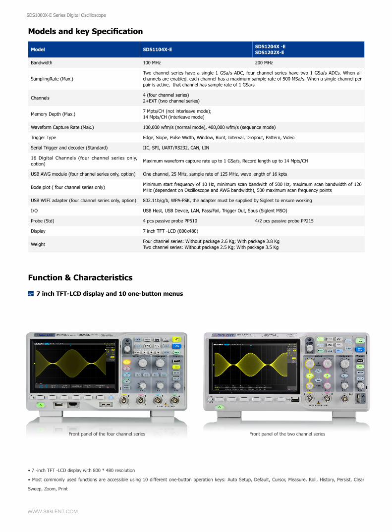
• 7 -inch TFT -LCD display with 800 * 480 resolution
• Most commonly used functions are accessible using 10 different one-button operation keys: Auto Setup, Default, Cursor, Measure, Roll, History, Persist, Clear
Sweep, Zoom, Print
7 inch TFT-LCD display and 10 one-button menus
Model SDS1104X-ESDS1204X -ESDS1202X-E
Bandwidth 100 MHz 200 MHz
SamplingRate (Max.)Two channel series have a single 1 GSa/s ADC, four channel series have two 1 GSa/s ADCs. When all channels are enabled, each channel has a maximum sample rate of 500 MSa/s. When a single channel per pair is active, that channel has sample rate of 1 GSa/s
Channels4 (four channel series)2+EXT (two channel series)
Memory Depth (Max.)7 Mpts/CH (not interleave mode);14 Mpts/CH (interleave mode)
Waveform Capture Rate (Max.) 100,000 wfm/s (normal mode), 400,000 wfm/s (sequence mode)
Trigger Type Edge, Slope, Pulse Width, Window, Runt, Interval, Dropout, Pattern, Video
Serial Trigger and decoder (Standard) IIC, SPI, UART/RS232, CAN, LIN
16 Digital Channels (four channel series only, option)
Maximum waveform capture rate up to 1 GSa/s, Record length up to 14 Mpts/CH
USB AWG module (four channel series only, option) One channel, 25 MHz, sample rate of 125 MHz, wave length of 16 kpts
Bode plot ( four channel series only)Minimum start frequency of 10 Hz, minimum scan bandwith of 500 Hz, maximum scan bandwidth of 120 MHz (dependent on Oscilloscope and AWG bandwidth), 500 maximum scan frequency points
USB WIFI adapter (four channel series only, option) 802.11b/g/b, WPA-PSK, the adapter must be supplied by Siglent to ensure working
I/O USB Host, USB Device, LAN, Pass/Fail, Trigger Out, Sbus (Siglent MSO)
Probe (Std) 4 pcs passive probe PP510 4/2 pcs passive probe PP215
Display 7 inch TFT -LCD (800x480)
WeightFour channel series: Without package 2.6 Kg; With package 3.8 KgTwo channel series: Without package 2.5 Kg; With package 3.5 Kg
Front panel of the four channel series Front panel of the two channel series
SDS1000X-E Series Digital Oscilloscope
WWW.SIGLENT.COM
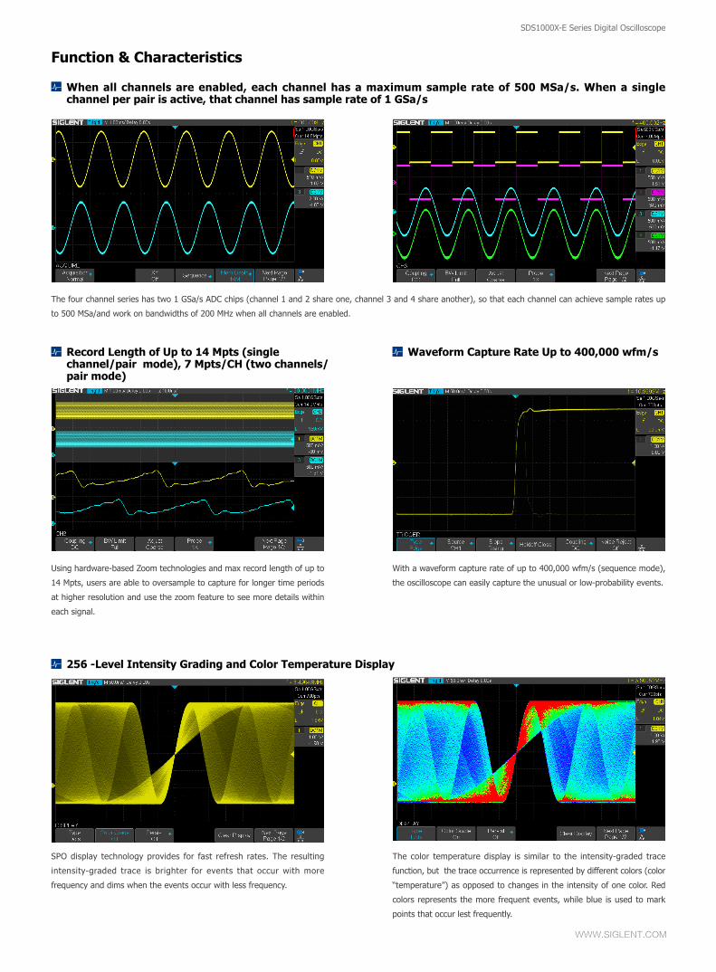
When all channels are enabled, each channel has a maximum sample rate of 500 MSa/s. When a single channel per pair is active, that channel has sample rate of 1 GSa/s
256 -Level Intensity Grading and Color Temperature Display
Record Length of Up to 14 Mpts (single channel/pair mode), 7 Mpts/CH (two channels/pair mode)
Waveform Capture Rate Up to 400,000 wfm/s
The four channel series has two 1 GSa/s ADC chips (channel 1 and 2 share one, channel 3 and 4 share another), so that each channel can achieve sample rates up
to 500 MSa/and work on bandwidths of 200 MHz when all channels are enabled.
SPO display technology provides for fast refresh rates. The resulting
intensity-graded trace is brighter for events that occur with more
frequency and dims when the events occur with less frequency.
The color temperature display is similar to the intensity-graded trace
function, but the trace occurrence is represented by different colors (color
“temperature”) as opposed to changes in the intensity of one color. Red
colors represents the more frequent events, while blue is used to mark
points that occur lest frequently.
With a waveform capture rate of up to 400,000 wfm/s (sequence mode),
the oscilloscope can easily capture the unusual or low-probability events.
Using hardware-based Zoom technologies and max record length of up to
14 Mpts, users are able to oversample to capture for longer time periods
at higher resolution and use the zoom feature to see more details within
each signal.
Function & Characteristics
SDS1000X-E Series Digital Oscilloscope
WWW.SIGLENT.COM
SDS1000X-E Series Digital Oscilloscope
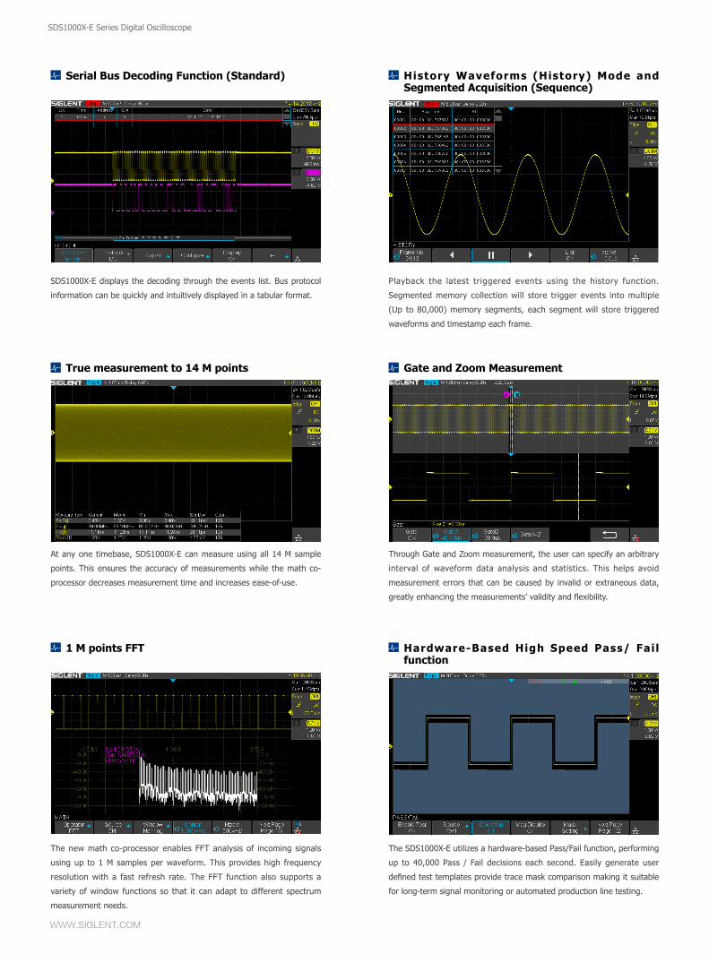
True measurement to 14 M points
Serial Bus Decoding Function (Standard)
Gate and Zoom Measurement
History Waveforms (History) Mode and Segmented Acquisition (Sequence)
At any one timebase, SDS1000X-E can measure using all 14 M sample
points. This ensures the accuracy of measurements while the math co-
processor decreases measurement time and increases ease-of-use.
SDS1000X-E displays the decoding through the events list. Bus protocol
information can be quickly and intuitively displayed in a tabular format.
Through Gate and Zoom measurement, the user can specify an arbitrary
interval of waveform data analysis and statistics. This helps avoid
measurement errors that can be caused by invalid or extraneous data,
greatly enhancing the measurements’ validity and flexibility.
Playback the latest triggered events using the history function.
Segmented memory collection will store trigger events into multiple
(Up to 80,000) memory segments, each segment will store triggered
waveforms and timestamp each frame.
1 M points FFT Hardware-Based High Speed Pass/ Fail function
The new math co-processor enables FFT analysis of incoming signals
using up to 1 M samples per waveform. This provides high frequency
resolution with a fast refresh rate. The FFT function also supports a
variety of window functions so that it can adapt to different spectrum
measurement needs.
The SDS1000X-E utilizes a hardware-based Pass/Fail function, performing
up to 40,000 Pass / Fail decisions each second. Easily generate user
defined test templates provide trace mask comparison making it suitable
for long-term signal monitoring or automated production line testing.
SDS1000X-E Series Digital Oscilloscope
WWW.SIGLENT.COM
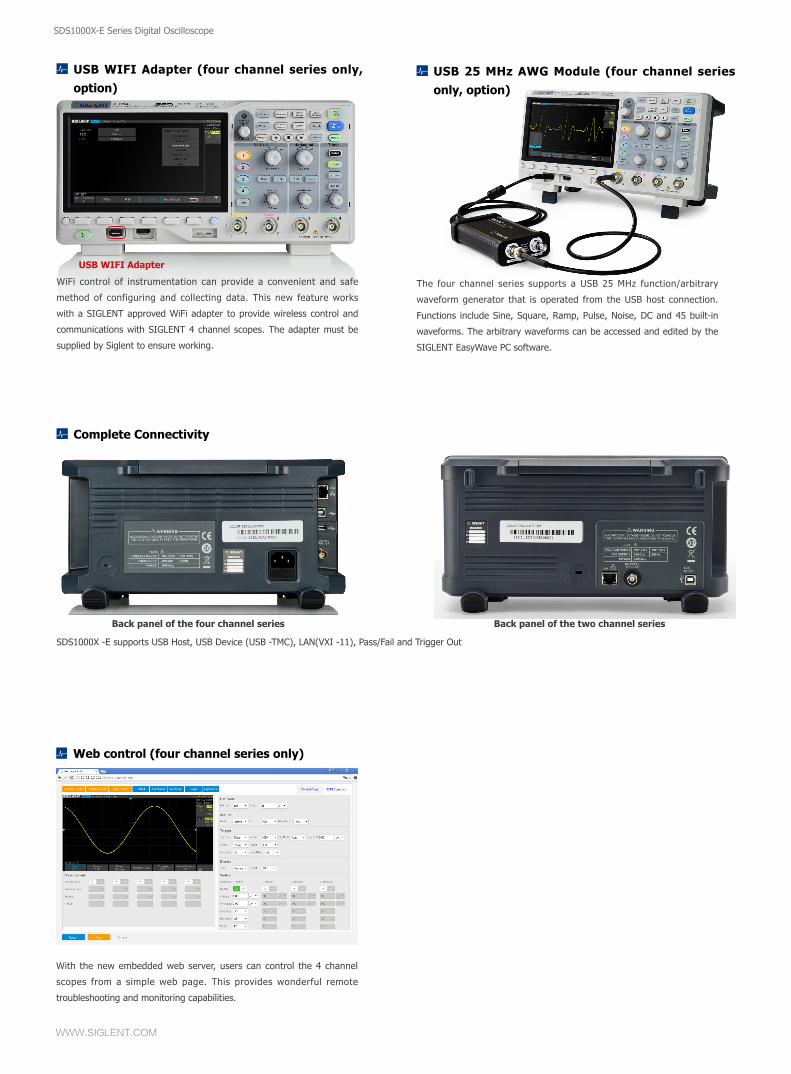
Search and Navigate (four channel series only)
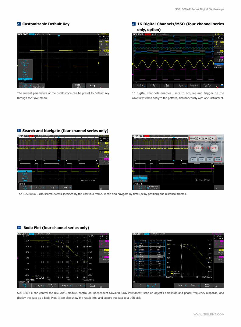
Customizable Default Key 16 Digital Channels/MSO (four channel series only, option)
The SDS1000X-E can search events specified by the user in a frame. It can also navigate by time (delay position) and historical frames.
The current parameters of the oscilloscope can be preset to Default Key
through the Save menu.
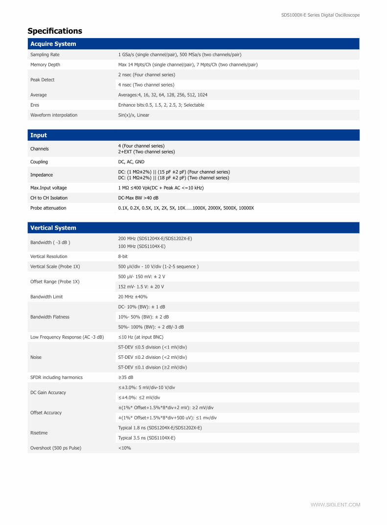
Bode Plot (four channel series only)
SDS1000X-E can control the USB AWG module, control an independent SIGLENT SDG instrument, scan an object’s amplitude and phase frequency response, and
display the data as a Bode Plot. It can also show the result lists, and export the data to a USB disk.
16 digital channels enables users to acquire and trigger on the
waveforms then analyze the pattern, simultaneously with one instrument.
SDS1000X-E Series Digital Oscilloscope
WWW.SIGLENT.COM
SDS1000X-E Series Digital Oscilloscope
Complete Connectivity
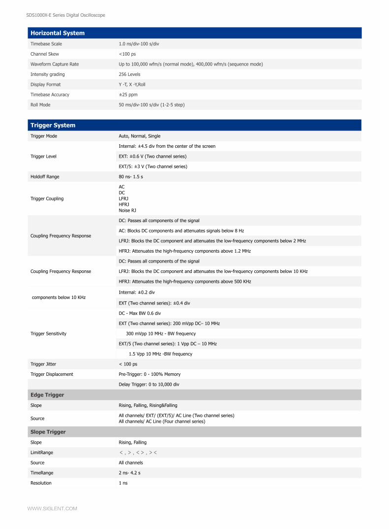
USB WIFI Adapter (four channel series only, option)
USB 25 MHz AWG Module (four channel series only, option)
Web control (four channel series only)
SDS1000X -E supports USB Host, USB Device (USB -TMC), LAN(VXI -11), Pass/Fail and Trigger Out
WiFi control of instrumentation can provide a convenient and safe
method of configuring and collecting data. This new feature works
with a SIGLENT approved WiFi adapter to provide wireless control and
communications with SIGLENT 4 channel scopes. The adapter must be
supplied by Siglent to ensure working.
The four channel series supports a USB 25 MHz function/arbitrary
waveform generator that is operated from the USB host connection.
Functions include Sine, Square, Ramp, Pulse, Noise, DC and 45 built-in
waveforms. The arbitrary waveforms can be accessed and edited by the
SIGLENT EasyWave PC software.
With the new embedded web server, users can control the 4 channel
scopes from a simple web page. This provides wonderful remote
troubleshooting and monitoring capabilities.
USB WIFI Adapter
Back panel of the four channel series Back panel of the two channel series
SDS1000X-E Series Digital Oscilloscope
WWW.SIGLENT.COM
Acquire System
Sampling Rate 1 GSa/s (single channel/pair), 500 MSa/s (two channels/pair)
Memory Depth Max 14 Mpts/Ch (single channel/pair), 7 Mpts/Ch (two channels/pair)
Peak Detect2 nsec (Four channel series)
4 nsec (Two channel series)
Average Averages:4, 16, 32, 64, 128, 256, 512, 1024
Eres Enhance bits:0.5, 1.5, 2, 2.5, 3; Selectable
Waveform interpolation Sin(x)/x, Linear
Specifications
Input
Channels4 (Four channel series)2+EXT (Two channel series)
Coupling DC, AC, GND
ImpedanceDC: (1 MΩ±2%) || (15 pF ±2 pF) (Four channel series)DC: (1 MΩ±2%) || (18 pF ±2 pF) (Two channel series)
Max.Input voltage 1 MΩ ≤400 Vpk(DC + Peak AC <=10 kHz)
CH to CH Isolation DC-Max BW >40 dB
Probe attenuation 0.1X, 0.2X, 0.5X, 1X, 2X, 5X, 10X……1000X, 2000X, 5000X, 10000X
Vertical System
Bandwidth ( -3 dB )200 MHz (SDS1204X-E/SDS1202X-E)
100 MHz (SDS1104X-E)
Vertical Resolution 8-bit
Vertical Scale (Probe 1X) 500 μV/div - 10 V/div (1-2-5 sequence )
Offset Range (Probe 1X)500 μV- 150 mV: ± 2 V
152 mV- 1.5 V: ± 20 V
Bandwidth Limit 20 MHz ±40%
Bandwidth Flatness
DC- 10% (BW): ± 1 dB
10%- 50% (BW): ± 2 dB
50%- 100% (BW): + 2 dB/-3 dB
Low Frequency Response (AC -3 dB) ≤10 Hz (at input BNC)
Noise
ST-DEV ≤0.5 division (<1 mV/div)
ST-DEV ≤0.2 division (<2 mV/div)
ST-DEV ≤0.1 division (≥2 mV/div)
SFDR including harmonics ≥35 dB
DC Gain Accuracy≤±3.0%: 5 mV/div-10 V/div
≤±4.0%: ≤2 mV/div
Offset Accuracy±(1%* Offset+1.5%*8*div+2 mV): ≥2 mV/div
±(1%* Offset+1.5%*8*div+500 uV): ≤1 mv/div
RisetimeTypical 1.8 ns (SDS1204X-E/SDS1202X-E)
Typical 3.5 ns (SDS1104X-E)
Overshoot (500 ps Pulse) <10%
SDS1000X-E Series Digital Oscilloscope
WWW.SIGLENT.COM
SDS1000X-E Series Digital Oscilloscope
Horizontal System
Timebase Scale 1.0 ns/div-100 s/div
Channel Skew <100 ps
Waveform Capture Rate Up to 100,000 wfm/s (normal mode), 400,000 wfm/s (sequence mode)
Intensity grading 256 Levels
Display Format Y -T, X -Y,Roll
Timebase Accuracy ±25 ppm
Roll Mode 50 ms/div-100 s/div (1-2-5 step)
Trigger System
Trigger Mode Auto, Normal, Single
Trigger Level
Internal: ±4.5 div from the center of the screen
EXT: ±0.6 V (Two channel series)
EXT/5: ±3 V (Two channel series)
Holdoff Range 80 ns- 1.5 s
Trigger Coupling
ACDCLFRJHFRJNoise RJ
Coupling Frequency Response
DC: Passes all components of the signal
AC: Blocks DC components and attenuates signals below 8 Hz
LFRJ: Blocks the DC component and attenuates the low-frequency components below 2 MHz
HFRJ: Attenuates the high-frequency components above 1.2 MHz
Coupling Frequency Response
DC: Passes all components of the signal
LFRJ: Blocks the DC component and attenuates the low-frequency components below 10 KHz
HFRJ: Attenuates the high-frequency components above 500 KHz
components below 10 KHzInternal: ±0.2 div
EXT (Two channel series): ±0.4 div
Trigger Sensitivity
DC - Max BW 0.6 div
EXT (Two channel series): 200 mVpp DC– 10 MHz
300 mVpp 10 MHz - BW frequency
EXT/5 (Two channel series): 1 Vpp DC – 10 MHz
1.5 Vpp 10 MHz -BW frequency
Trigger Jitter < 100 ps
Trigger Displacement Pre-Trigger: 0 - 100% Memory
Delay Trigger: 0 to 10,000 div
Edge Trigger
Slope Rising, Falling, Rising&Falling
SourceAll channels/ EXT/ (EXT/5)/ AC Line (Two channel series)All channels/ AC Line (Four channel series)
Slope Trigger
Slope Rising, Falling
LimitRange < , > , <> , ><
Source All channels
TimeRange 2 ns- 4.2 s
Resolution 1 ns
SDS1000X-E Series Digital Oscilloscope
WWW.SIGLENT.COM
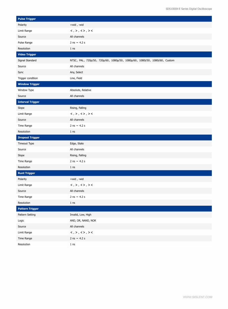
Pulse Trigger
Polarity +wid , -wid
Limit Range < , > , <> , ><
Source All channels
Pulse Range 2 ns ~ 4.2 s
Resolution 1 ns
Video Trigger
Signal Standard NTSC,PAL,720p/50,720p/60,1080p/50,1080p/60,1080i/50,1080i/60,Custom
Source All channels
Sync Any, Select
Trigger condition Line, Field
Window Trigger
Window Type Absolute, Relative
Source All channels
Interval Trigger
Slope Rising, Falling
Limit Range < , > , <> , ><
Source All channels
Time Range 2 ns ~ 4.2 s
Resolution 1 ns
Dropout Trigger
Timeout Type Edge, State
Source All channels
Slope Rising, Falling
Time Range 2 ns ~ 4.2 s
Resolution 1 ns
Runt Trigger
Polarity +wid , -wid
Limit Range < , > , <> , ><
Source All channels
Time Range 2 ns ~ 4.2 s
Resolution 1 ns
Pattern Trigger
Pattern Setting Invalid, Low, High
Logic AND, OR, NAND, NOR
Source All channels
Limit Range < , > , <> , ><
Time Range 2 ns ~ 4.2 s
Resolution 1 ns
SDS1000X-E Series Digital Oscilloscope
WWW.SIGLENT.COM
SDS1000X-E Series Digital Oscilloscope
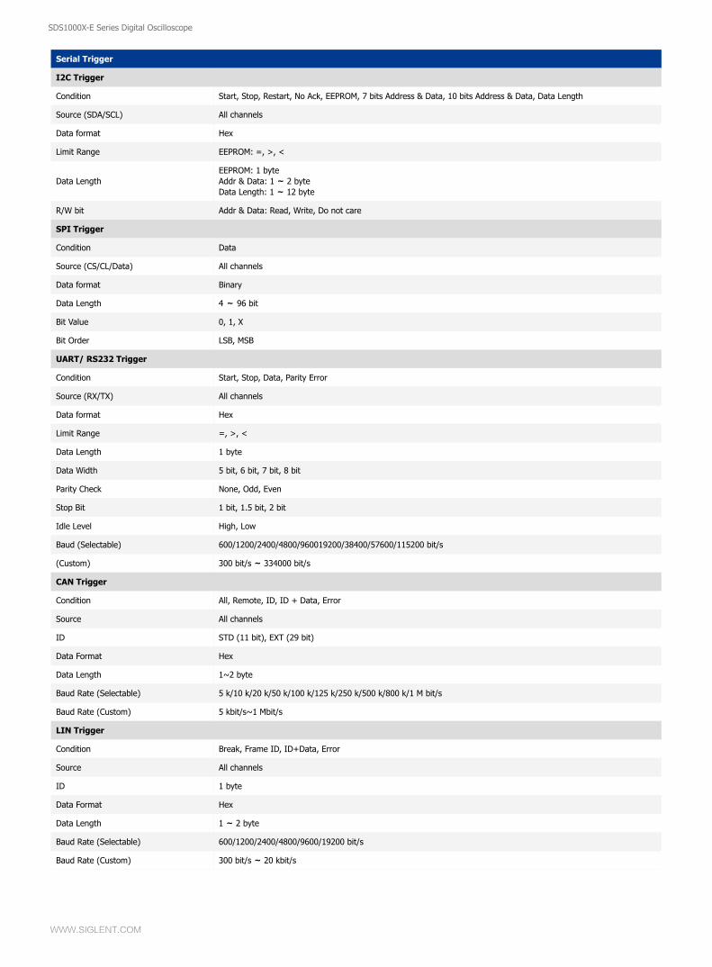
Serial Trigger
I2C Trigger
Condition Start, Stop, Restart, No Ack, EEPROM, 7 bits Address & Data, 10 bits Address & Data, Data Length
Source (SDA/SCL) All channels
Data format Hex
Limit Range EEPROM: =, >, <
Data LengthEEPROM: 1 byteAddr & Data: 1 ~ 2 byteData Length: 1 ~ 12 byte
R/W bit Addr & Data: Read, Write, Do not care
SPI Trigger
Condition Data
Source (CS/CL/Data) All channels
Data format Binary
Data Length 4 ~ 96 bit
Bit Value 0, 1, X
Bit Order LSB, MSB
UART/ RS232 Trigger
Condition Start, Stop, Data, Parity Error
Source (RX/TX) All channels
Data format Hex
Limit Range =, >, <
Data Length 1 byte
Data Width 5 bit, 6 bit, 7 bit, 8 bit
Parity Check None, Odd, Even
Stop Bit 1 bit, 1.5 bit, 2 bit
Idle Level High, Low
Baud (Selectable) 600/1200/2400/4800/960019200/38400/57600/115200 bit/s
(Custom) 300 bit/s ~ 334000 bit/s
CAN Trigger
Condition All, Remote, ID, ID + Data, Error
Source All channels
ID STD (11 bit), EXT (29 bit)
Data Format Hex
Data Length 1~2 byte
Baud Rate (Selectable) 5 k/10 k/20 k/50 k/100 k/125 k/250 k/500 k/800 k/1 M bit/s
Baud Rate (Custom) 5 kbit/s~1 Mbit/s
LIN Trigger
Condition Break, Frame ID, ID+Data, Error
Source All channels
ID 1 byte
Data Format Hex
Data Length 1 ~ 2 byte
Baud Rate (Selectable) 600/1200/2400/4800/9600/19200 bit/s
Baud Rate (Custom) 300 bit/s ~ 20 kbit/s
SDS1000X-E Series Digital Oscilloscope
WWW.SIGLENT.COM
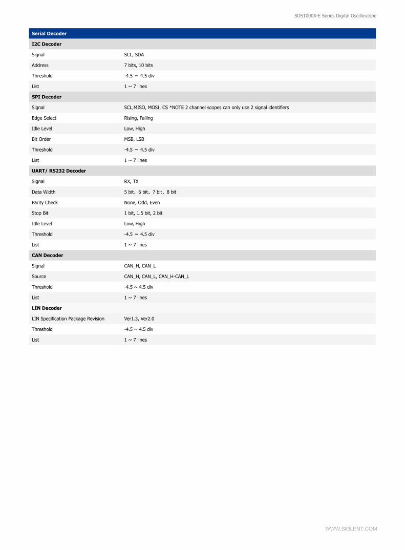
Serial Decoder
I2C Decoder
Signal SCL, SDA
Address 7 bits, 10 bits
Threshold -4.5 ~ 4.5 div
List 1 ~ 7 lines
SPI Decoder
Signal SCL,MISO, MOSI, CS *NOTE 2 channel scopes can only use 2 signal identifiers
Edge Select Rising, Falling
Idle Level Low, High
Bit Order MSB, LSB
Threshold -4.5 ~ 4.5 div
List 1 ~ 7 lines
UART/ RS232 Decoder
Signal RX, TX
Data Width 5 bit,6 bit,7 bit,8 bit
Parity Check None, Odd, Even
Stop Bit 1 bit, 1.5 bit, 2 bit
Idle Level Low, High
Threshold -4.5 ~ 4.5 div
List 1 ~ 7 lines
CAN Decoder
Signal CAN_H, CAN_L
Source CAN_H, CAN_L, CAN_H-CAN_L
Threshold -4.5 ~ 4.5 div
List 1 ~ 7 lines
LIN Decoder
LIN Specification Package Revision Ver1.3, Ver2.0
Threshold -4.5 ~ 4.5 div
List 1 ~ 7 lines
SDS1000X-E Series Digital Oscilloscope
WWW.SIGLENT.COM
SDS1000X-E Series Digital Oscilloscope
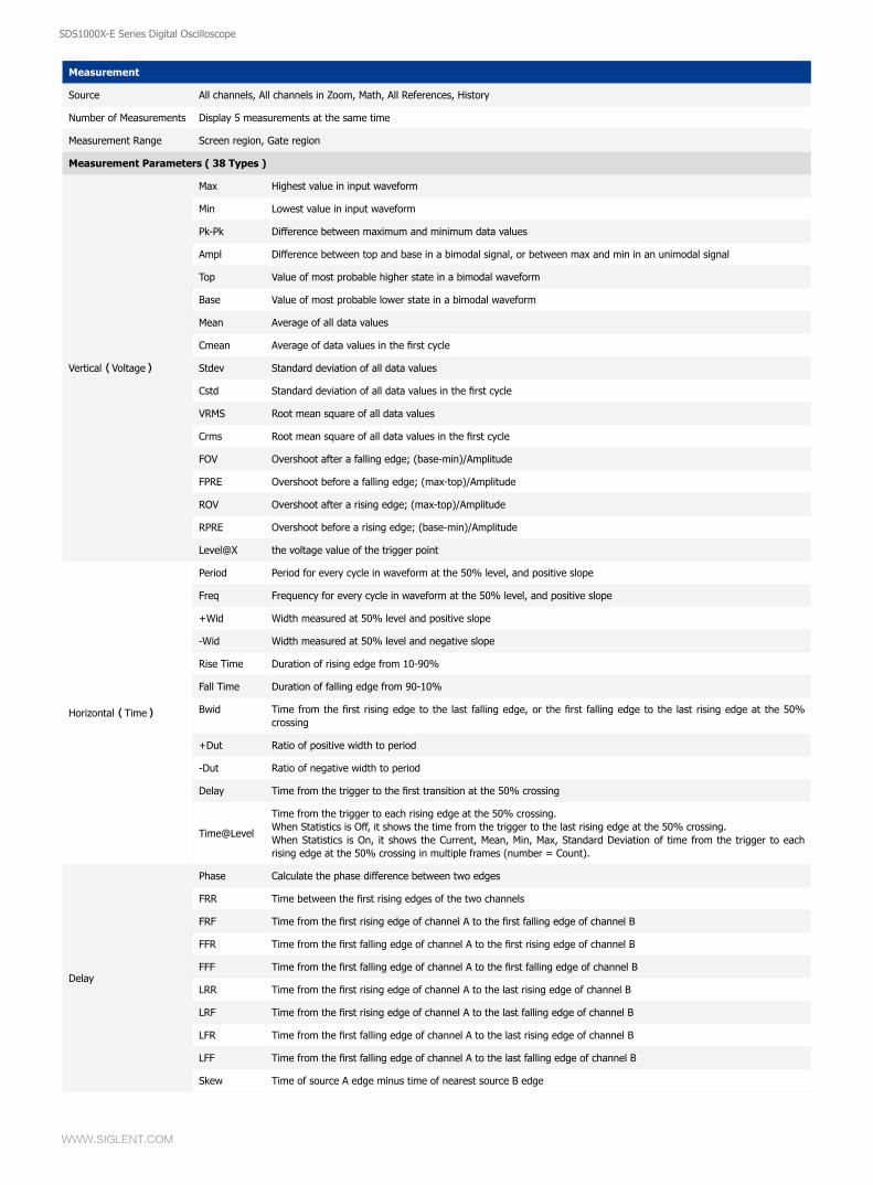
Measurement
Source All channels, All channels in Zoom, Math, All References, History
Number of Measurements Display 5 measurements at the same time
Measurement Range Screen region, Gate region
Measurement Parameters ( 38 Types )
Vertical(Voltage)
Max Highest value in input waveform
Min Lowest value in input waveform
Pk-Pk Difference between maximum and minimum data values
Ampl Difference between top and base in a bimodal signal, or between max and min in an unimodal signal
Top Value of most probable higher state in a bimodal waveform
Base Value of most probable lower state in a bimodal waveform
Mean Average of all data values
Cmean Average of data values in the first cycle
Stdev Standard deviation of all data values
Cstd Standard deviation of all data values in the first cycle
VRMS Root mean square of all data values
Crms Root mean square of all data values in the first cycle
FOV Overshoot after a falling edge; (base-min)/Amplitude
FPRE Overshoot before a falling edge; (max-top)/Amplitude
ROV Overshoot after a rising edge; (max-top)/Amplitude
RPRE Overshoot before a rising edge; (base-min)/Amplitude
Level@X the voltage value of the trigger point
Horizontal(Time)
Period Period for every cycle in waveform at the 50% level, and positive slope
Freq Frequency for every cycle in waveform at the 50% level, and positive slope
+Wid Width measured at 50% level and positive slope
-Wid Width measured at 50% level and negative slope
Rise Time Duration of rising edge from 10-90%
Fall Time Duration of falling edge from 90-10%
Bwid Time from the first rising edge to the last falling edge, or the first falling edge to the last rising edge at the 50% crossing
+Dut Ratio of positive width to period
-Dut Ratio of negative width to period
Delay Time from the trigger to the first transition at the 50% crossing
Time@Level
Time from the trigger to each rising edge at the 50% crossing.When Statistics is Off, it shows the time from the trigger to the last rising edge at the 50% crossing.When Statistics is On, it shows the Current, Mean, Min, Max, Standard Deviation of time from the trigger to each rising edge at the 50% crossing in multiple frames (number = Count).
Delay
Phase Calculate the phase difference between two edges
FRR Time between the first rising edges of the two channels
FRF Time from the first rising edge of channel A to the first falling edge of channel B
FFR Time from the first falling edge of channel A to the first rising edge of channel B
FFF Time from the first falling edge of channel A to the first falling edge of channel B
LRR Time from the first rising edge of channel A to the last rising edge of channel B
LRF Time from the first rising edge of channel A to the last falling edge of channel B
LFR Time from the first falling edge of channel A to the last rising edge of channel B
LFF Time from the first falling edge of channel A to the last falling edge of channel B
Skew Time of source A edge minus time of nearest source B edge
SDS1000X-E Series Digital Oscilloscope
WWW.SIGLENT.COM
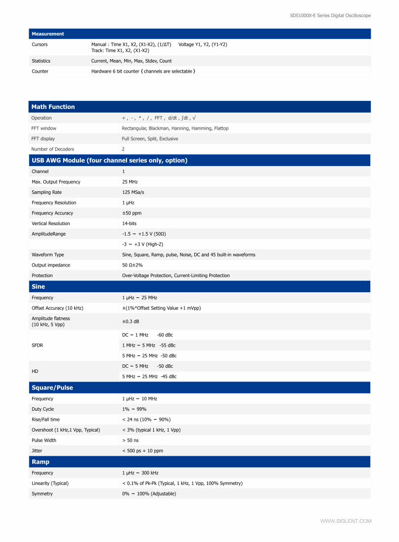
Math Function
Operation + , - , * , / , FFT , d/dt , ∫dt , √
FFT window Rectangular, Blackman, Hanning, Hamming, Flattop
FFT display Full Screen, Split, Exclusive
Number of Decoders 2
USB AWG Module (four channel series only, option)
Channel 1
Max. Output Frequency 25 MHz
Sampling Rate 125 MSa/s
Frequency Resolution 1 μHz
Frequency Accuracy ±50 ppm
Vertical Resolution 14-bits
AmplitudeRange -1.5 ~ +1.5 V (50Ω)
-3 ~ +3 V (High-Z)
Waveform Type Sine, Square, Ramp, pulse, Noise, DC and 45 built-in waveforms
Output impedance 50 Ω±2%
Protection Over-Voltage Protection, Current-Limiting Protection
Sine
Frequency 1 μHz ~ 25 MHz
Offset Accuracy (10 kHz) ±(1%*Offset Setting Value +1 mVpp)
Amplitude flatness(10 kHz, 5 Vpp)
±0.3 dB
SFDR
DC ~ 1 MHz -60 dBc
1 MHz ~ 5 MHz -55 dBc
5 MHz ~ 25 MHz -50 dBc
HDDC ~ 5 MHz -50 dBc
5 MHz ~ 25 MHz -45 dBc
Square/Pulse
Frequency 1 μHz ~ 10 MHz
Duty Cycle 1% ~ 99%
Rise/Fall time < 24 ns (10% ~ 90%)
Overshoot (1 kHz,1 Vpp, Typical) < 3% (typical 1 kHz, 1 Vpp)
Pulse Width > 50 ns
Jitter < 500 ps + 10 ppm
Ramp
Frequency 1 μHz ~ 300 kHz
Linearity (Typical) < 0.1% of Pk-Pk (Typical, 1 kHz, 1 Vpp, 100% Symmetry)
Symmetry 0% ~ 100% (Adjustable)
Cursors Manual : Time X1, X2, (X1-X2), (1/ΔT) Voltage Y1, Y2, (Y1-Y2)Track: Time X1, X2, (X1-X2)
Statistics Current, Mean, Min, Max, Stdev, Count
Counter Hardware 6 bit counter(channels are selectable)
Measurement
SDS1000X-E Series Digital Oscilloscope
WWW.SIGLENT.COM
SDS1000X-E Series Digital Oscilloscope
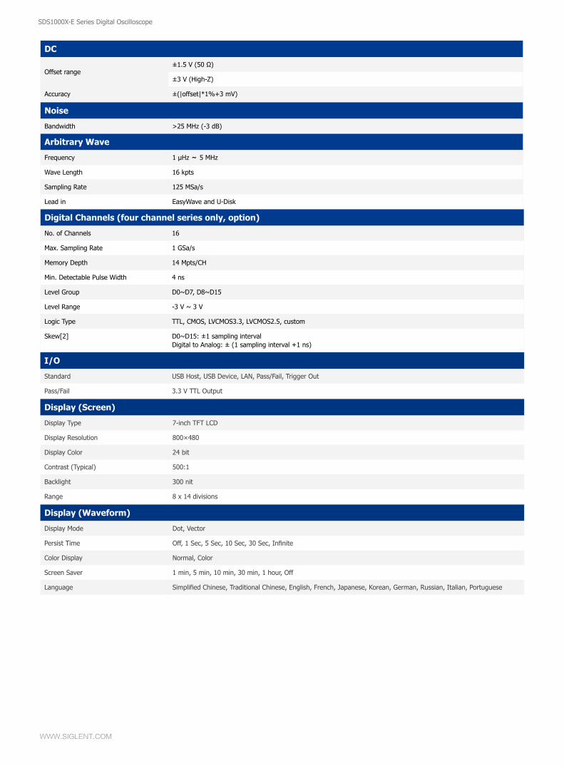
I/O
Standard USB Host, USB Device, LAN, Pass/Fail, Trigger Out
Pass/Fail 3.3 V TTL Output
Display (Screen)
Display Type 7-inch TFT LCD
Display Resolution 800×480
Display Color 24 bit
Contrast (Typical) 500:1
Backlight 300 nit
Range 8 x 14 divisions
Display (Waveform)
Display Mode Dot, Vector
Persist Time Off, 1 Sec, 5 Sec, 10 Sec, 30 Sec, Infinite
Color Display Normal, Color
Screen Saver 1 min, 5 min, 10 min, 30 min, 1 hour, Off
Language Simplified Chinese, Traditional Chinese, English, French, Japanese, Korean, German, Russian, Italian, Portuguese
Noise
Bandwidth >25 MHz (-3 dB)
Arbitrary Wave
Frequency 1 μHz ~ 5 MHz
Wave Length 16 kpts
Sampling Rate 125 MSa/s
Lead in EasyWave and U-Disk
Digital Channels (four channel series only, option)
No. of Channels 16
Max. Sampling Rate 1 GSa/s
Memory Depth 14 Mpts/CH
Min. Detectable Pulse Width 4 ns
Level Group D0~D7, D8~D15
Level Range -3 V ~ 3 V
Logic Type TTL, CMOS, LVCMOS3.3, LVCMOS2.5, custom
Skew[2] D0~D15: ±1 sampling intervalDigital to Analog: ± (1 sampling interval +1 ns)
DC
Offset range±1.5 V (50 Ω)
±3 V (High-Z)
Accuracy ±(|offset|*1%+3 mV)
SDS1000X-E Series Digital Oscilloscope
WWW.SIGLENT.COM
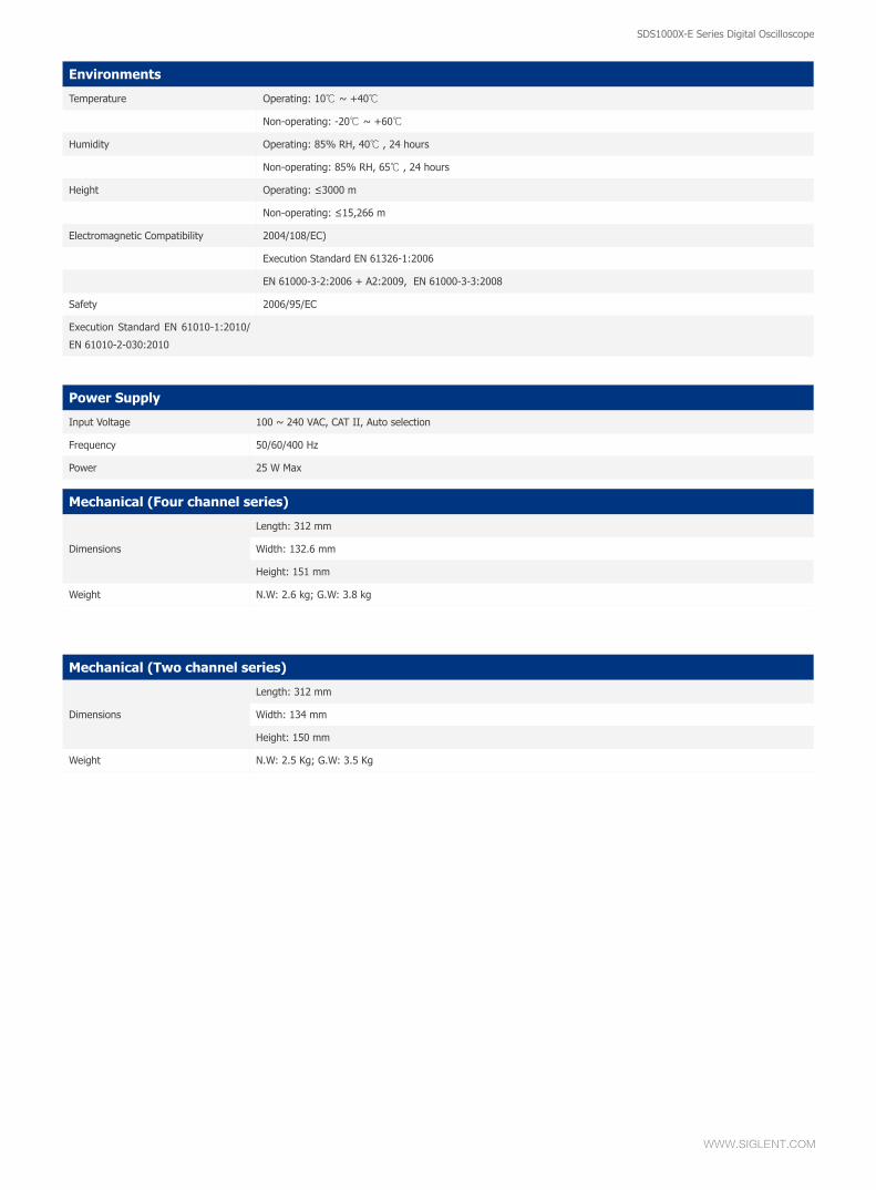
Environments
Temperature Operating: 10℃ ~ +40℃
Non-operating: -20℃ ~ +60℃
Humidity Operating: 85% RH, 40℃ , 24 hours
Non-operating: 85% RH, 65℃ , 24 hours
Height Operating: ≤3000 m
Non-operating: ≤15,266 m
Electromagnetic Compatibility 2004/108/EC)
Execution Standard EN 61326-1:2006
EN 61000-3-2:2006 + A2:2009, EN 61000-3-3:2008
Safety 2006/95/EC
Execution Standard EN 61010-1:2010/
EN 61010-2-030:2010
Power Supply
Input Voltage 100 ~ 240 VAC, CAT II, Auto selection
Frequency 50/60/400 Hz
Power 25 W Max
Mechanical (Four channel series)
Dimensions
Length: 312 mm
Width: 132.6 mm
Height: 151 mm
Weight N.W: 2.6 kg; G.W: 3.8 kg
Mechanical (Two channel series)
Dimensions
Length: 312 mm
Width: 134 mm
Height: 150 mm
Weight N.W: 2.5 Kg; G.W: 3.5 Kg
SDS1000X-E Series Digital Oscilloscope
WWW.SIGLENT.COM
SDS1000X-E Series Digital Oscilloscope
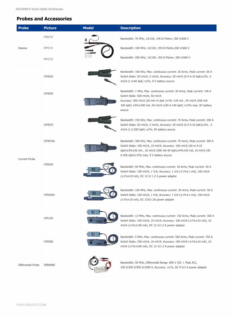
Probe Picture Model Description
PB470 Bandwidth: 70 MHz, 1X/10X, 1M/10 Mohm, 300 V/600 V
Bandwidth: 100 MHz, 1X/10X, 1M/10 Mohm,300 V/600 V
Bandwidth: 200 MHz, 1X/10X, 1M/10 Mohm, 300 V/600 V
Passive PP510
PP215
Current Probe
CP4020
Bandwidth: 100 KHz, Max. continuous current: 20 Arms, Peak current: 60 A
Switch Ratio: 50 mV/A, 5 mV/A, Accuracy: 50 mV/A (0.4 A-10 Apk)±2%, 5
mV/A (1 A-60 Apk) ±2%, 9 V battery source
CP4050Bandwidth: 1 MHz, Max. continuous current: 50 Arms, Peak current: 140 A
Switch Ratio: 500 mV/A, 50 mV/A
Accuracy: 500 mV/A (20 mA-14 ApK )±3% ±20 mA , 50 mV/A (200 mA-
100 ApK) ±4%±200 mA, 50 mV/A (100 A-140 ApK) ±15% max, 9V battery
source
CP4070
Bandwidth: 150 KHz, Max. continuous current: 70 Arms, Peak current: 200 A
Switch Ratio: 50 mV/A, 5 mV/A, Accuracy: 50 mV/A (0.4 A-10 ApK)±2% , 5
mV/A (1 A-200 ApK) ±2%, 9V battery source
CP4070A Bandwidth: 300 KHz, Max. continuous current: 70 Arms, Peak current: 200 A
Switch Ratio: 100 mV/A, 10 mV/A, Accuracy: 100 mV/A (50 m A-10
ApK)±3%±50 mA , 10 mV/A (500 mA-40 ApK)±4%±50 mA, 10 mV/A (40
A-200 ApK)±15% max, 9 V battery source
CP5030Bandwidth: 50 MHz, Max. continuous current: 30 Arms, Peak current: 50 A
Switch Ratio: 100 mV/A, 1 V/A, Accuracy: 1 V/A (±1%±1 mA), 100 mV/A
(±1%±10 mA), DC 12 V/ 1.2 A power adapter
CP5030A
Bandwidth: 100 MHz, Max. continuous current: 30 Arms, Peak current: 50 A
Switch Ratio: 100 mV/A, 1 V/A, Accuracy: 1 V/A (±1%±1 mA), 100 mV/A
(±1%±10 mA), DC 12V/1.2A power adapter
CP5150Bandwidth: 12 MHz, Max. continuous current: 150 Arms, Peak current: 300 A
Switch Ratio: 100 mV/A, 10 mV/A, Accuracy: 100 mV/A (±1%±10 mA), 10
mV/A (±1%±100 mA), DC 12 V/1.2 A power adapter
CP5500
Bandwidth: 5 MHz, Max. continuous current: 500 Arms, Peak current: 750 A
Switch Ratio: 100 mV/A, 10 mV/A, Accuracy: 100 mV/A (±1%±10 mA), 10
mV/A (±1%±100 mA), DC 12 V/1.2 A power adapter
Differential Probe DPB4080Bandwidth: 50 MHz, Differential Range: 800 V (DC + Peak AC),
100 X/200 X/500 X/1000 X, Accuracy: ±1%, DC 9 V/1 A power adapter
Probes and Accessories
SDS1000X-E Series Digital Oscilloscope
WWW.SIGLENT.COM
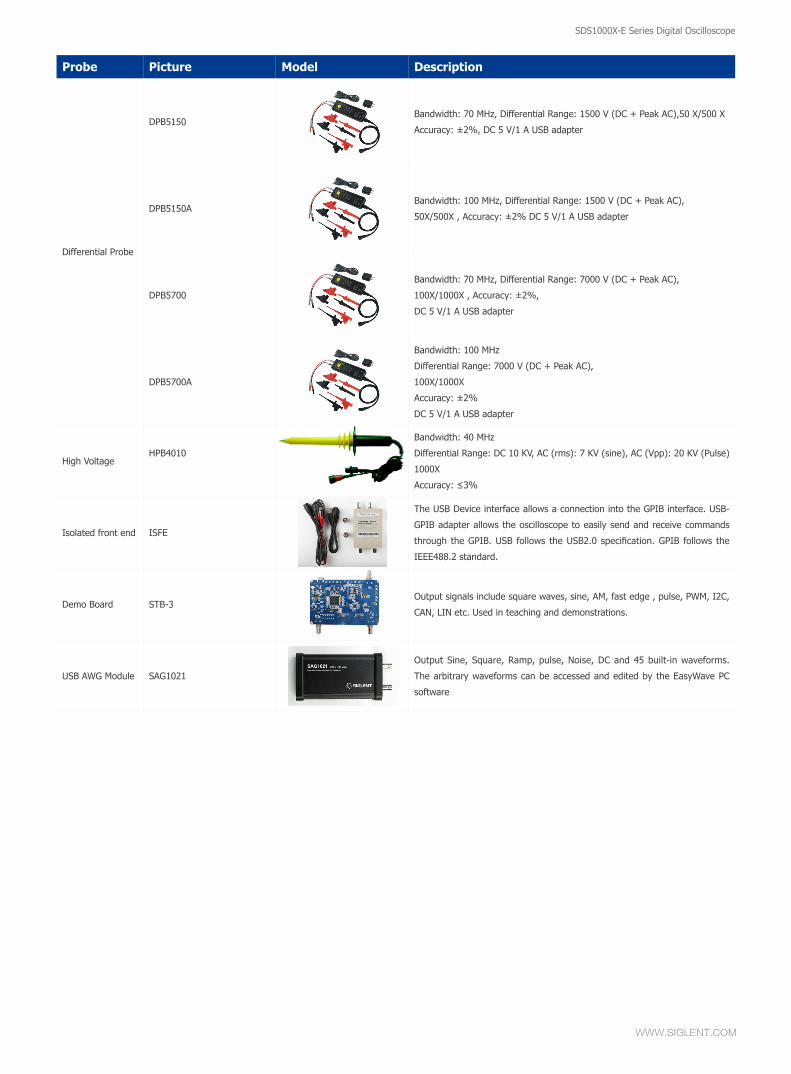
Probe Picture Model Description
Differential Probe
DPB5150Bandwidth: 70 MHz, Differential Range: 1500 V (DC + Peak AC),50 X/500 X
Accuracy: ±2%, DC 5 V/1 A USB adapter
DPB5150ABandwidth: 100 MHz, Differential Range: 1500 V (DC + Peak AC),
50X/500X , Accuracy: ±2% DC 5 V/1 A USB adapter
DPB5700
Bandwidth: 70 MHz, Differential Range: 7000 V (DC + Peak AC),
100X/1000X , Accuracy: ±2%,
DC 5 V/1 A USB adapter
DPB5700A
Bandwidth: 100 MHz
Differential Range: 7000 V (DC + Peak AC),
100X/1000X
Accuracy: ±2%
DC 5 V/1 A USB adapter
High VoltageHPB4010
Bandwidth: 40 MHz
Differential Range: DC 10 KV, AC (rms): 7 KV (sine), AC (Vpp): 20 KV (Pulse)
1000X
Accuracy: ≤3%
Isolated front end ISFE
The USB Device interface allows a connection into the GPIB interface. USB-
GPIB adapter allows the oscilloscope to easily send and receive commands
through the GPIB. USB follows the USB2.0 specification. GPIB follows the
IEEE488.2 standard.
Demo Board STB-3Output signals include square waves, sine, AM, fast edge , pulse, PWM, I2C,
CAN, LIN etc. Used in teaching and demonstrations.
USB AWG Module SAG1021
Output Sine, Square, Ramp, pulse, Noise, DC and 45 built-in waveforms.
The arbitrary waveforms can be accessed and edited by the EasyWave PC
software
SDS1000X-E Series Digital Oscilloscope
WWW.SIGLENT.COM
SDS1000X-E Series Digital Oscilloscope
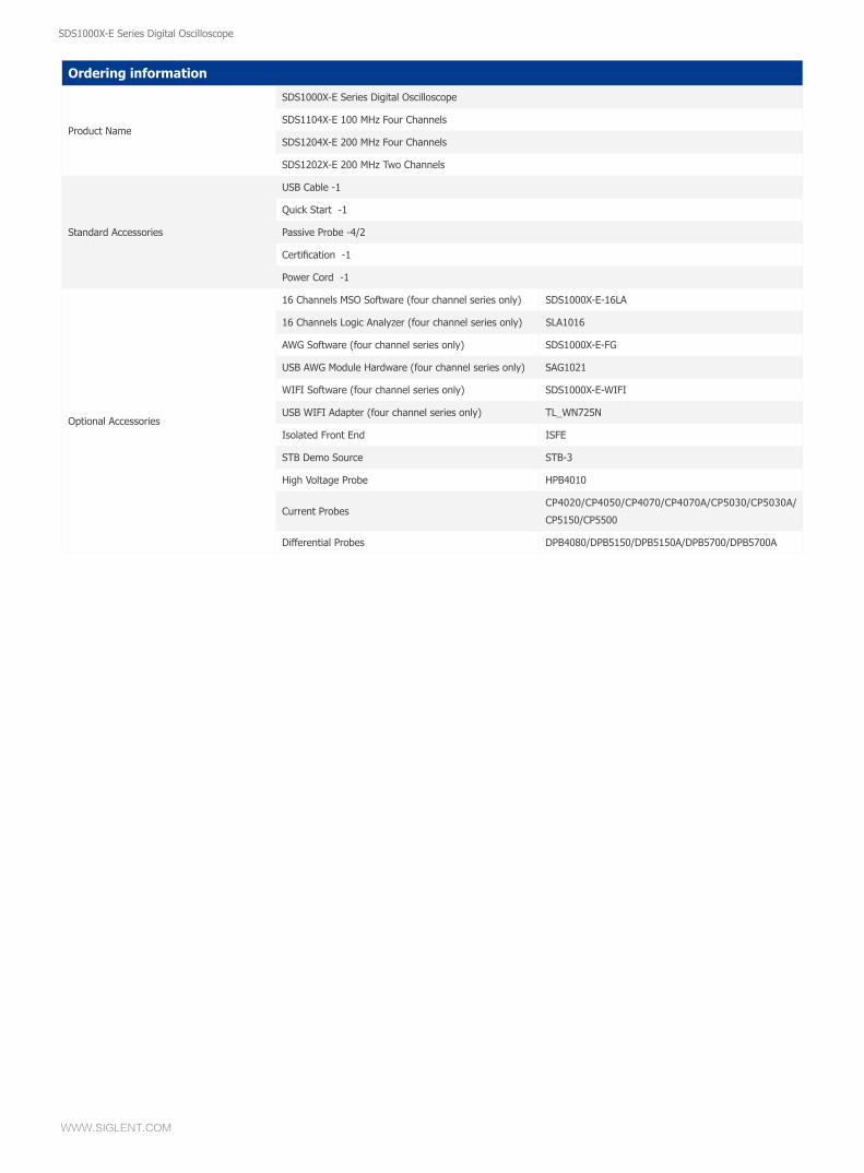
Ordering information
Product Name
SDS1000X-E Series Digital Oscilloscope
SDS1104X-E 100 MHz Four Channels
SDS1204X-E 200 MHz Four Channels
SDS1202X-E 200 MHz Two Channels
Standard Accessories
USB Cable -1
Quick Start -1
Passive Probe -4/2
Certification -1
Power Cord -1
Optional Accessories
16 Channels MSO Software (four channel series only) SDS1000X-E-16LA
16 Channels Logic Analyzer (four channel series only) SLA1016
AWG Software (four channel series only) SDS1000X-E-FG
USB AWG Module Hardware (four channel series only) SAG1021
WIFI Software (four channel series only) SDS1000X-E-WIFI
USB WIFI Adapter (four channel series only) TL_WN725N
Isolated Front End ISFE
STB Demo Source STB-3
High Voltage Probe HPB4010
Current ProbesCP4020/CP4050/CP4070/CP4070A/CP5030/CP5030A/
CP5150/CP5500
Differential Probes DPB4080/DPB5150/DPB5150A/DPB5700/DPB5700A
Headquarter:SIGLENT TECHNOLOGIES CO., LTD.Add: Bldg No.4 & No.5, Antongda Industrial Zone, 3rd Liuxian Road, Bao'an District, Shenzhen, 518101, China. Tel: + 86 755 3661 5186Fax: + 86 755 3359 1582Email: [email protected]; Website: http://www.siglent.com/ens/
USA:SIGLENT Technologies America, Inc6557 Cochran Rd Solon, Ohio 44139Tel: 440-398-5800Toll Free: 877-515-5551Fax: 440-399-1211Email: [email protected]: www.siglentamerica.com
Europe:SIGLENT TECHNOLOGIES EUROPE GmbH ADD: Liebigstrasse 2-20, Gebaeude 14, 22113 Hamburg Germany Tel: +49(0)-819-95946Fax: +49(0)-819-95947Email: [email protected]: www.siglenteu.com
About SIGLENT
SIGLENT is an international high-tech company, concentrating on R&D, sales, production and services of electronic test & measurement instruments.
SIGLENT first began developing digital oscilloscopes independently in 2002. After more than a decade of continuous development, SIGLENT has extended its product line to include digital oscilloscopes, function/arbitrary waveform generators, digital multimeters, DC power supplies, spectrum analyzers, isolated handheld oscilloscopes and other general purpose test instrumentation. Since its first oscilloscope, the ADS7000 series, was launched in 2005, SIGLENT has become the fastest growing manufacturer of digital oscilloscopes. We firmly believe that today SIGLENT is the best value in electronic test & measurement.
Follow us on Facebook: SiglentTech
SDS1000X-ESeries Super Phosphor Oscilloscope


![Measurement of Characteristic Impedance of Silicon Fiber ...Digital Phosphor Oscilloscope 3054 of 500 MHz and a MARS VC97 Digital Multimeter [12] [13]. The circuit diagram with original](https://img.pdfslide.us/doc/110x75/5f6387d75bae1175ac762f59/measurement-of-characteristic-impedance-of-silicon-fiber-digital-phosphor-oscilloscope.jpg)