Embed Size (px)
Citation preview

SUM
MER
201
3 Included second instalment of
The History of Radio and Radio Control
1
2
Boating Down my Way As I said, in my last article about boating in the cold, I don’t. I leave that to the younger and fitter types. Which brings me nicely to the start of our official springtime and warmer weather. Whilst writing this (22nd March), the News has just come on the televi-sion and with it the weather forecast, spring is to be accompanied by Snow, Rain, High Winds, Flooding and subzero temperatures.
That said, the South Coast has gotten off relativity lightly, with just the last two put-ting their oar in. My other local club, the Solent Radio Control MBC, has held their first spring show. Copying previous years format, the exhibition was in support of the RNLI. As the venue is not large, there is only room for some fifty plus boats, depending on their size of course. As Graham well knows, there is sometimes more exhibits than table space allows for so a selection has to be made; for the sake of balance, unless of course, there is a strong theme. The RNLI, often gives fund raising events a pretty substantial box of goodies to hand out to the viewing public, the public in their turn, often donate to the charity. For our five hours on the Saturday, we collected £704.53, a rate of £140.00 per hour, not bad for a bunch of O.A.P’s. To date, the grand total raised through this event is over £10,000. I am sad to say, in this part of the country, there is always support for an event which features the RNLI. Whereas, other charitable events do not generate any-where near the same level of interest. I guess I should not be too surprised, but it is unbalanced.
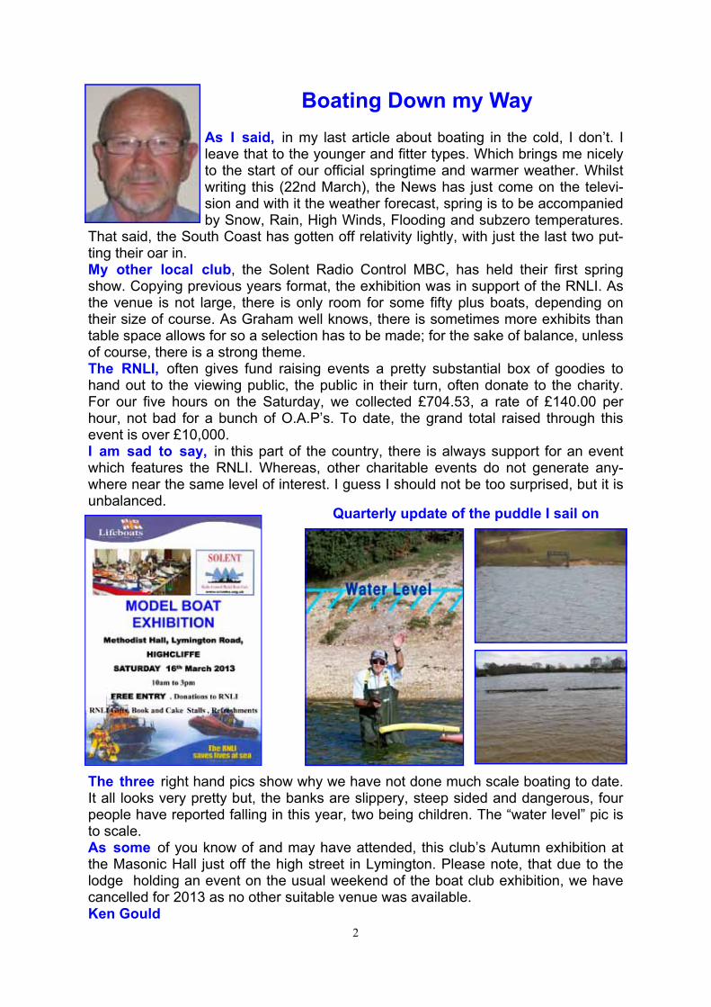
The three right hand pics show why we have not done much scale boating to date. It all looks very pretty but, the banks are slippery, steep sided and dangerous, four people have reported falling in this year, two being children. The “water level” pic is to scale. As some of you know of and may have attended, this club’s Autumn exhibition at the Masonic Hall just off the high street in Lymington. Please note, that due to the lodge holding an event on the usual weekend of the boat club exhibition, we have cancelled for 2013 as no other suitable venue was available. Ken Gould
Quarterly update of the puddle I sail on
3
Milton Keynes IPMS 2013
After last year’s debacle at the show cause by snow, this year’s show was re dated from February to April. Hopefully the theory being, that the weather would be better! How right they were!! So, after Tony Martin had got the show booked and the boats organ-ised for collection etc., the day of the show arrived. It is an early start as we have to book in at 8am so I picked up Mike Skuse and Tony Dalton. Tony Martin and James were going up, Terry Martin
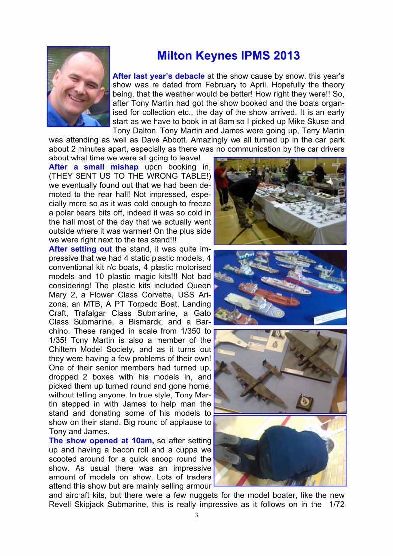
was attending as well as Dave Abbott. Amazingly we all turned up in the car park about 2 minutes apart, especially as there was no communication by the car drivers about what time we were all going to leave! After a small mishap upon booking in, (THEY SENT US TO THE WRONG TABLE!) we eventually found out that we had been de-moted to the rear hall! Not impressed, espe-cially more so as it was cold enough to freeze a polar bears bits off, indeed it was so cold in the hall most of the day that we actually went outside where it was warmer! On the plus side we were right next to the tea stand!!! After setting out the stand, it was quite im-pressive that we had 4 static plastic models, 4 conventional kit r/c boats, 4 plastic motorised models and 10 plastic magic kits!!! Not bad considering! The plastic kits included Queen Mary 2, a Flower Class Corvette, USS Ari-zona, an MTB, A PT Torpedo Boat, Landing Craft, Trafalgar Class Submarine, a Gato Class Submarine, a Bismarck, and a Bar-chino. These ranged in scale from 1/350 to 1/35! Tony Martin is also a member of the Chiltern Model Society, and as it turns out they were having a few problems of their own! One of their senior members had turned up, dropped 2 boxes with his models in, and picked them up turned round and gone home, without telling anyone. In true style, Tony Mar-tin stepped in with James to help man the stand and donating some of his models to show on their stand. Big round of applause to Tony and James. The show opened at 10am, so after setting up and having a bacon roll and a cuppa we scooted around for a quick snoop round the show. As usual there was an impressive amount of models on show. Lots of traders attend this show but are mainly selling armour and aircraft kits, but there were a few nuggets for the model boater, like the new Revell Skipjack Submarine, this is really impressive as it follows on in the 1/72
4
scale that Revell have been using on their previous submarines. (Gato, type viic/41 and type viic/43). Also the type 45 destroyer from Airfix at £45, plus the Italieri kits in 1/35 of the MAS, MTB and PT boats. As most of the motley crew were wander-ing the show, it became apparent that Dave Abbott had secreted himself in the warm cafeteria for a couple of hours, Terry Martin had something in his hand and was eating all day, Tony Martin was on the Chiltern stand and myself Mike and Tony Dalton
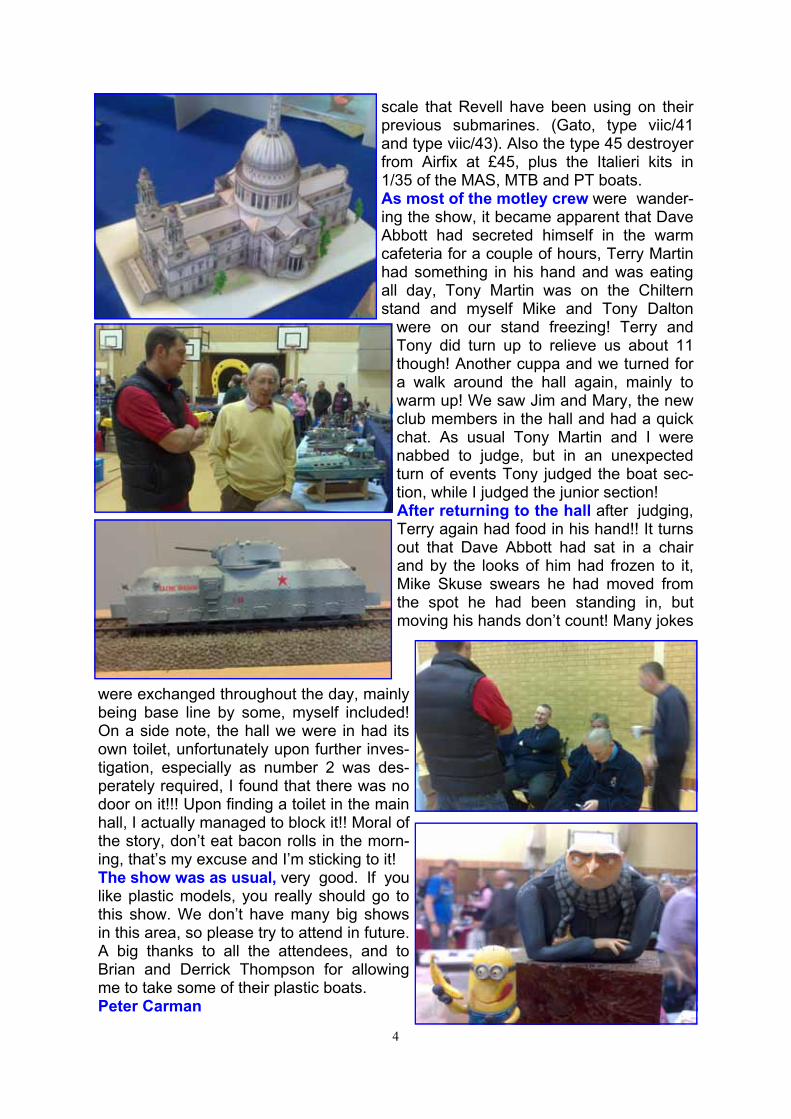
were on our stand freezing! Terry and Tony did turn up to relieve us about 11 though! Another cuppa and we turned for a walk around the hall again, mainly to warm up! We saw Jim and Mary, the new club members in the hall and had a quick chat. As usual Tony Martin and I were nabbed to judge, but in an unexpected turn of events Tony judged the boat sec-tion, while I judged the junior section! After returning to the hall after judging, Terry again had food in his hand!! It turns out that Dave Abbott had sat in a chair and by the looks of him had frozen to it, Mike Skuse swears he had moved from the spot he had been standing in, but moving his hands don’t count! Many jokes
were exchanged throughout the day, mainly being base line by some, myself included! On a side note, the hall we were in had its own toilet, unfortunately upon further inves-tigation, especially as number 2 was des-perately required, I found that there was no door on it!!! Upon finding a toilet in the main hall, I actually managed to block it!! Moral of the story, don’t eat bacon rolls in the morn-ing, that’s my excuse and I’m sticking to it! The show was as usual, very good. If you like plastic models, you really should go to this show. We don’t have many big shows in this area, so please try to attend in future. A big thanks to all the attendees, and to Brian and Derrick Thompson for allowing me to take some of their plastic boats. Peter Carman
5
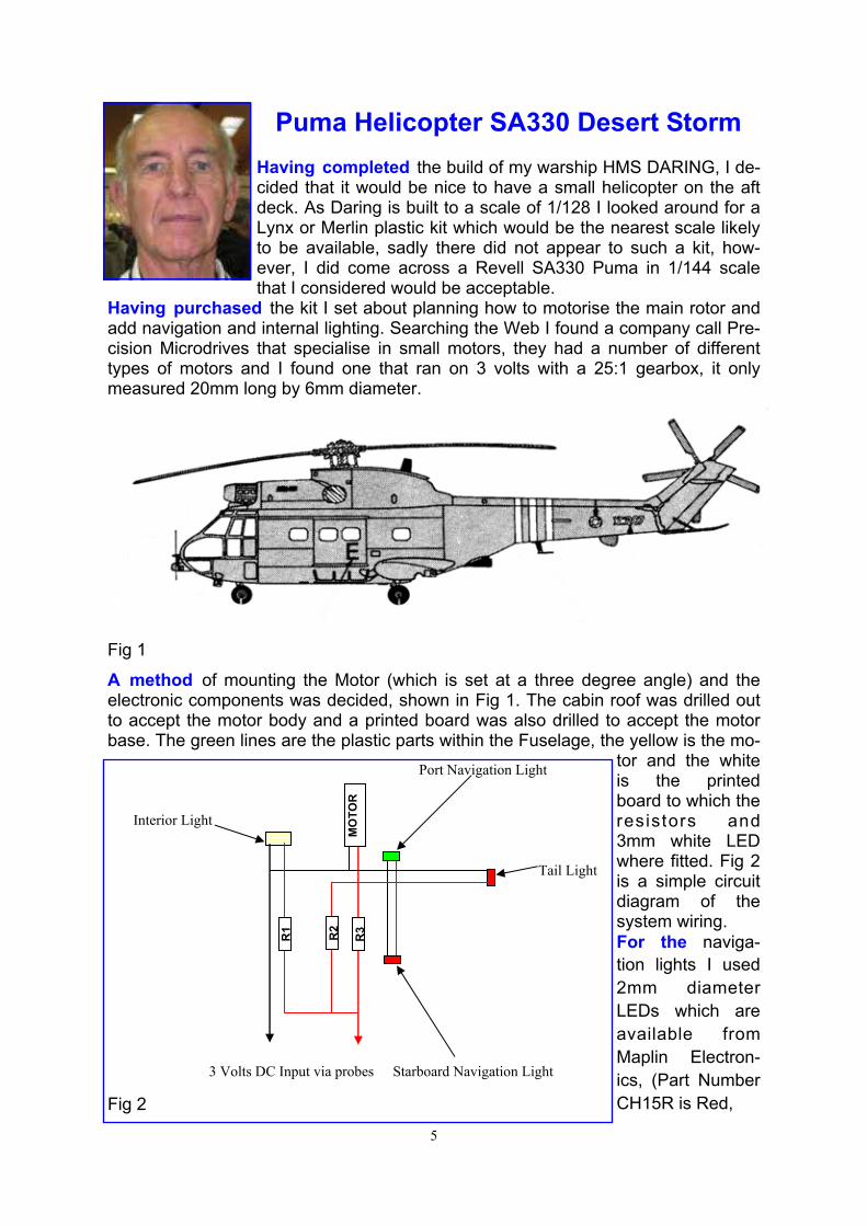
Puma Helicopter SA330 Desert Storm Having completed the build of my warship HMS DARING, I de-cided that it would be nice to have a small helicopter on the aft deck. As Daring is built to a scale of 1/128 I looked around for a Lynx or Merlin plastic kit which would be the nearest scale likely to be available, sadly there did not appear to such a kit, how-ever, I did come across a Revell SA330 Puma in 1/144 scale that I considered would be acceptable.
Having purchased the kit I set about planning how to motorise the main rotor and add navigation and internal lighting. Searching the Web I found a company call Pre-cision Microdrives that specialise in small motors, they had a number of different types of motors and I found one that ran on 3 volts with a 25:1 gearbox, it only measured 20mm long by 6mm diameter.
A method of mounting the Motor (which is set at a three degree angle) and the electronic components was decided, shown in Fig 1. The cabin roof was drilled out to accept the motor body and a printed board was also drilled to accept the motor base. The green lines are the plastic parts within the Fuselage, the yellow is the mo-
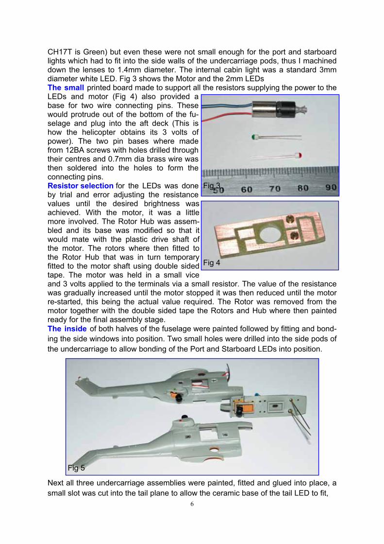
tor and the white is the printed board to which the resistors and 3mm white LED where fitted. Fig 2 is a simple circuit diagram of the system wiring. For the naviga-tion lights I used 2mm diameter LEDs which are available from Maplin Electron-ics, (Part Number CH15R is Red,
Port Navigation Light Interior Light
Tail Light
3 Volts DC Input via probes Starboard Navigation Light
R1 R2
MO
TOR
R
3
Fig 1
Fig 2
6
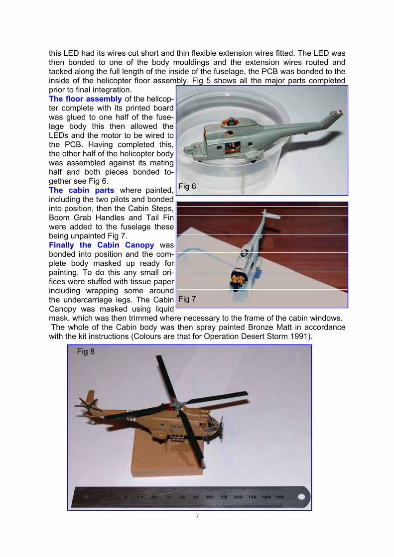
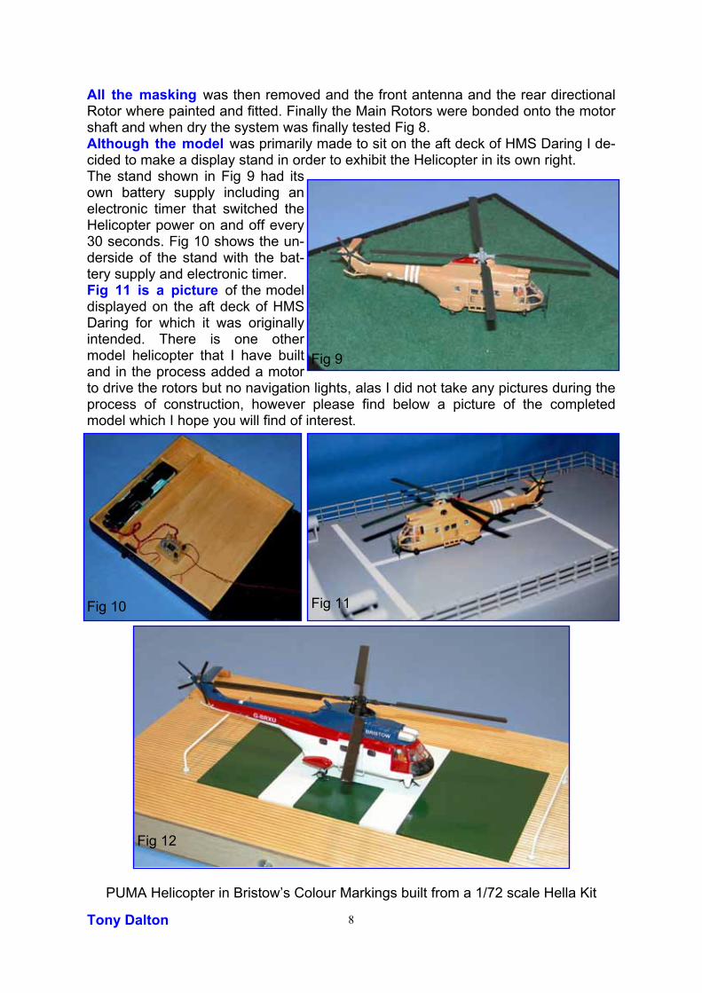
CH17T is Green) but even these were not small enough for the port and starboard lights which had to fit into the side walls of the undercarriage pods, thus I machined down the lenses to 1.4mm diameter. The internal cabin light was a standard 3mm diameter white LED. Fig 3 shows the Motor and the 2mm LEDs The small printed board made to support all the resistors supplying the power to the LEDs and motor (Fig 4) also provided a base for two wire connecting pins. These would protrude out of the bottom of the fu-selage and plug into the aft deck (This is how the helicopter obtains its 3 volts of power). The two pin bases where made from 12BA screws with holes drilled through their centres and 0.7mm dia brass wire was then soldered into the holes to form the connecting pins. Resistor selection for the LEDs was done by trial and error adjusting the resistance values until the desired brightness was achieved. With the motor, it was a little more involved. The Rotor Hub was assem-bled and its base was modified so that it would mate with the plastic drive shaft of the motor. The rotors where then fitted to the Rotor Hub that was in turn temporary fitted to the motor shaft using double sided tape. The motor was held in a small vice and 3 volts applied to the terminals via a small resistor. The value of the resistance was gradually increased until the motor stopped it was then reduced until the motor re-started, this being the actual value required. The Rotor was removed from the motor together with the double sided tape the Rotors and Hub where then painted ready for the final assembly stage. The inside of both halves of the fuselage were painted followed by fitting and bond-ing the side windows into position. Two small holes were drilled into the side pods of the undercarriage to allow bonding of the Port and Starboard LEDs into position.
Next all three undercarriage assemblies were painted, fitted and glued into place, a small slot was cut into the tail plane to allow the ceramic base of the tail LED to fit,
Fig 3
Fig 4
Fig 5
7
this LED had its wires cut short and thin flexible extension wires fitted. The LED was then bonded to one of the body mouldings and the extension wires routed and tacked along the full length of the inside of the fuselage, the PCB was bonded to the inside of the helicopter floor assembly. Fig 5 shows all the major parts completed prior to final integration. The floor assembly of the helicop-ter complete with its printed board was glued to one half of the fuse-lage body this then allowed the LEDs and the motor to be wired to the PCB. Having completed this, the other half of the helicopter body was assembled against its mating half and both pieces bonded to-gether see Fig 6. The cabin parts where painted, including the two pilots and bonded into position, then the Cabin Steps, Boom Grab Handles and Tail Fin were added to the fuselage these being unpainted Fig 7. Finally the Cabin Canopy was bonded into position and the com-plete body masked up ready for painting. To do this any small ori-fices were stuffed with tissue paper including wrapping some around the undercarriage legs. The Cabin Canopy was masked using liquid mask, which was then trimmed where necessary to the frame of the cabin windows. The whole of the Cabin body was then spray painted Bronze Matt in accordance with the kit instructions (Colours are that for Operation Desert Storm 1991).
Fig 6
Fig 7
Fig 8
8
All the masking was then removed and the front antenna and the rear directional Rotor where painted and fitted. Finally the Main Rotors were bonded onto the motor shaft and when dry the system was finally tested Fig 8. Although the model was primarily made to sit on the aft deck of HMS Daring I de-cided to make a display stand in order to exhibit the Helicopter in its own right. The stand shown in Fig 9 had its own battery supply including an electronic timer that switched the Helicopter power on and off every 30 seconds. Fig 10 shows the un-derside of the stand with the bat-tery supply and electronic timer. Fig 11 is a picture of the model displayed on the aft deck of HMS Daring for which it was originally intended. There is one other model helicopter that I have built and in the process added a motor to drive the rotors but no navigation lights, alas I did not take any pictures during the process of construction, however please find below a picture of the completed model which I hope you will find of interest.
PUMA Helicopter in Bristow’s Colour Markings built from a 1/72 scale Hella Kit Tony Dalton
Fig 9
Fig 10
Fig 12
Fig 11
9
We always hear 'the rules' from the female side, now here are the rules from the male side. Please note they are all numbered '1' ON PURPOSE!
1. Men are NOT mind readers. 1. Learn to work the toilet seat. You're a big girl. If it's up, put it down. We need it up, you need it down. You don't hear us complaining about you leaving it down. 1. Sunday sports, it's like the full moon or the changing of the tides. Let it be. 1. Crying is blackmail and witchcraft. 1. Ask for what you want. Let us be clear on this one! Subtle hints do not work! Strong hints do not work! Obvious hints do not work! Just say it! 1. Yes and No are perfectly acceptable answers to almost every question. 1. Come to us with a problem only if you want help solving it. That's what we do. Sympathy is what your girlfriends are for. 1. Anything we said 6 months ago is inadmissible in an argument. In fact, all comments become Null and Void after 7 Days. 1. If you think you're fat, you probably are. Don't ask us. 1. If something we said can be interpreted two ways and one of the ways makes you sad or angry, we meant the other one. 1. You can either ask us to do something, or tell us how you want it done, not both. If you already know best how to do it, just do it yourself. 1. Whenever possible, please say whatever you have to say during commercials. 1. Christopher Columbus did NOT need directions and neither do we. 1. ALL men see in only 16 colours. Peach, for example, is a fruit, not a colour. Pumpkin is also a fruit. 1. If it itches, it will be scratched. We do that. 1. If we ask what is wrong and you say 'nothing,' we will act like nothing's wrong. We know you are lying, but it is just not worth the hassle. 1. If you ask a question you don't want an answer to, Expect an answer you don't want to hear. 1. When we have to go somewhere, absolutely anything you wear is fine... Really! 1. Don't ask us what we're thinking about unless you are prepared to discuss such topics as Football or golf. 1. You have enough clothes and too many shoes. 1. I am in shape. Round is a shape! 1. Thank you for reading this. Yes, I know I have to sleep on the couch tonight; but did you know men really don't mind that? It's like camping. I am indebted to John Weedon for this insight. Editor.
10
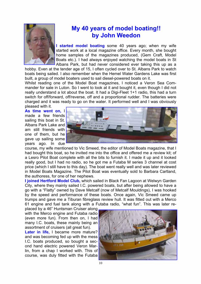
My 40 years of model boating!! by John Weedon
I started model boating some 40 years ago; when my wife started work at a local magazine office. Every month, she bought home samples of the magazines produced, (Gem Craft, Model Boats etc.). I had always enjoyed watching the model boats in St Albans Park, but had never considered ever taking this up as a
hobby. Even at the tender age of 15, I often cycled over to St. Albans Park to watch boats being sailed. I also remember when the Hemel Water Gardens Lake was first built, a group of model boaters used to sail diesel-powered boats on it. Whilst reading one of the Model Boat magazines, I noticed a Veron Sea Com-mander for sale in Luton. So I went to look at it and bought it, even though I did not really understand a lot about the boat. It had a Digi-Fleet 1+1 radio, this had a turn switch for off/forward, off/reverse, off and a proportional rudder. The batteries were charged and it was ready to go on the water. It performed well and I was obviously pleased with it. As time went on, I made a few friends sailing this boat in St. Albans Park Lake and am still friends with one of them, but he gave up sailing some years ago. In due course, my wife mentioned to Vic Smeed, the editor of Model Boats magazine, that I had bought this boat, so he invited me into the office and offered me a review kit; of a Lesro Pilot Boat complete with all the bits to furnish it. I made it up and it looked really good, but I had no radio, so he got me a Futaba M series 3 channel at cost price (which I still have to this day). The boat went really well and was later reviewed in Model Boats Magazine. The Pilot Boat was eventually sold to Barbara Cartland, the authoress, for one of her nephews. I joined Hertford Model Club, which sailed in Black Fan Lagoon at Welwyn Garden City, where they mainly sailed I.C. powered boats, but after being allowed to have a go with a “Flatty” owned by Dave Metcalf (now of Metcalf Mouldings), I was hooked by the speed and performance of these boats. Once again, Vic Smeed came up trumps and gave me a Tiburan fibreglass review hull. It was fitted out with a Merco 61 engine and fuel tank along with a Futaba radio, “what fun”. This was later re-placed by a 46” Huntsman Cruiser along with the Merco engine and Futaba radio (even more fun). From then on, I had many I.C. boats, these mainly being an assortment of cruisers (all great fun). Later in life, I became more mature? and was becoming fed up with the mess I.C. boats produced, so bought a sec-ond hand electric powered Veron Mar-lin, from a chap I worked with. This of course, was duly fitted with the Futaba
11
radio and I sailed it on St. Albans Lake. Sometime after this, my friend and I were chatting about the Hemel Hempstead Water Gardens Lake; for sailing model boats. The Council was approached, it agreed we could sail our boats on it, but no I.C’s were al-lowed. We built up a small club of about 10 people, at this time Health
and Safety was not mentioned and neither was Insurance. We sailed here for a few years, then a woman known locally as “the Swan Lady”, poked her nose in and claimed we were dis-turbing the wildlife, needless to say, she won and we were stopped from sailing. At this point, I stopped sailing for a while, I then noticed a piece in the local News Paper, regarding a new boat club being started in Chesham, I joined this club. Af-
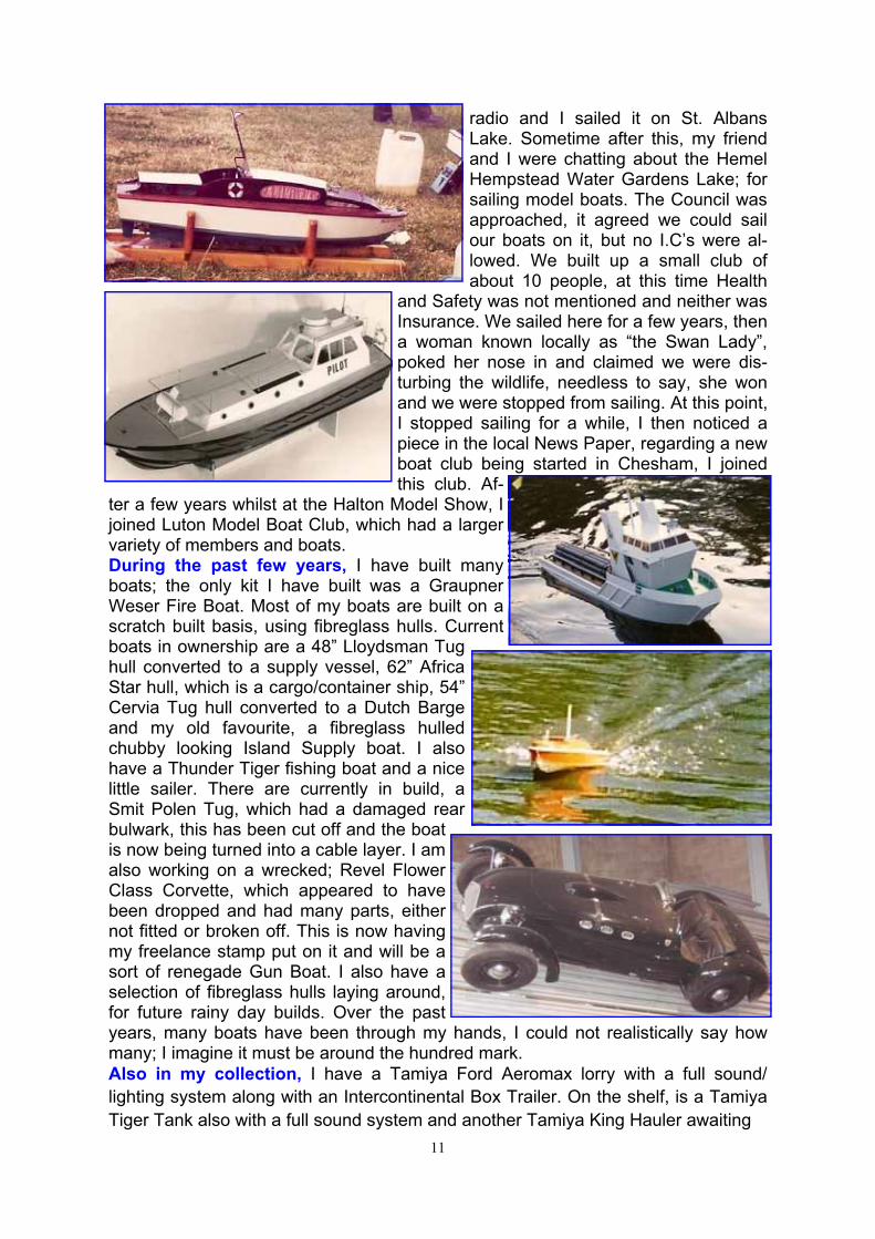
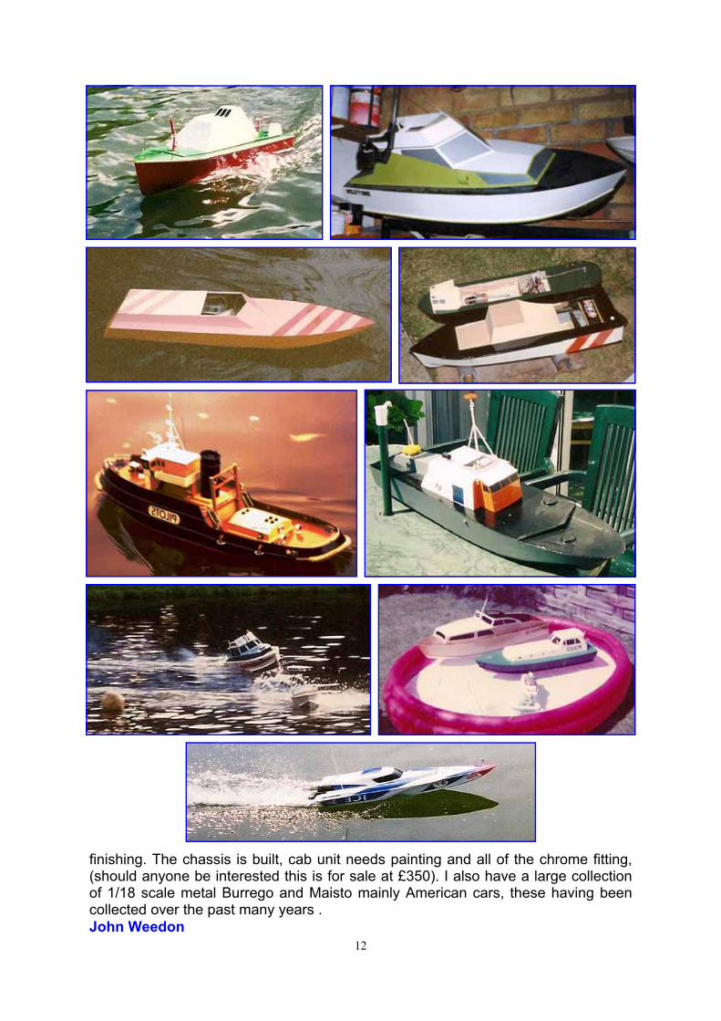
ter a few years whilst at the Halton Model Show, I joined Luton Model Boat Club, which had a larger variety of members and boats. During the past few years, I have built many boats; the only kit I have built was a Graupner Weser Fire Boat. Most of my boats are built on a scratch built basis, using fibreglass hulls. Current boats in ownership are a 48” Lloydsman Tug hull converted to a supply vessel, 62” Africa Star hull, which is a cargo/container ship, 54” Cervia Tug hull converted to a Dutch Barge and my old favourite, a fibreglass hulled chubby looking Island Supply boat. I also have a Thunder Tiger fishing boat and a nice little sailer. There are currently in build, a Smit Polen Tug, which had a damaged rear bulwark, this has been cut off and the boat is now being turned into a cable layer. I am also working on a wrecked; Revel Flower Class Corvette, which appeared to have been dropped and had many parts, either not fitted or broken off. This is now having my freelance stamp put on it and will be a sort of renegade Gun Boat. I also have a selection of fibreglass hulls laying around, for future rainy day builds. Over the past years, many boats have been through my hands, I could not realistically say how many; I imagine it must be around the hundred mark. Also in my collection, I have a Tamiya Ford Aeromax lorry with a full sound/lighting system along with an Intercontinental Box Trailer. On the shelf, is a Tamiya Tiger Tank also with a full sound system and another Tamiya King Hauler awaiting
12
finishing. The chassis is built, cab unit needs painting and all of the chrome fitting, (should anyone be interested this is for sale at £350). I also have a large collection of 1/18 scale metal Burrego and Maisto mainly American cars, these having been collected over the past many years . John Weedon
13
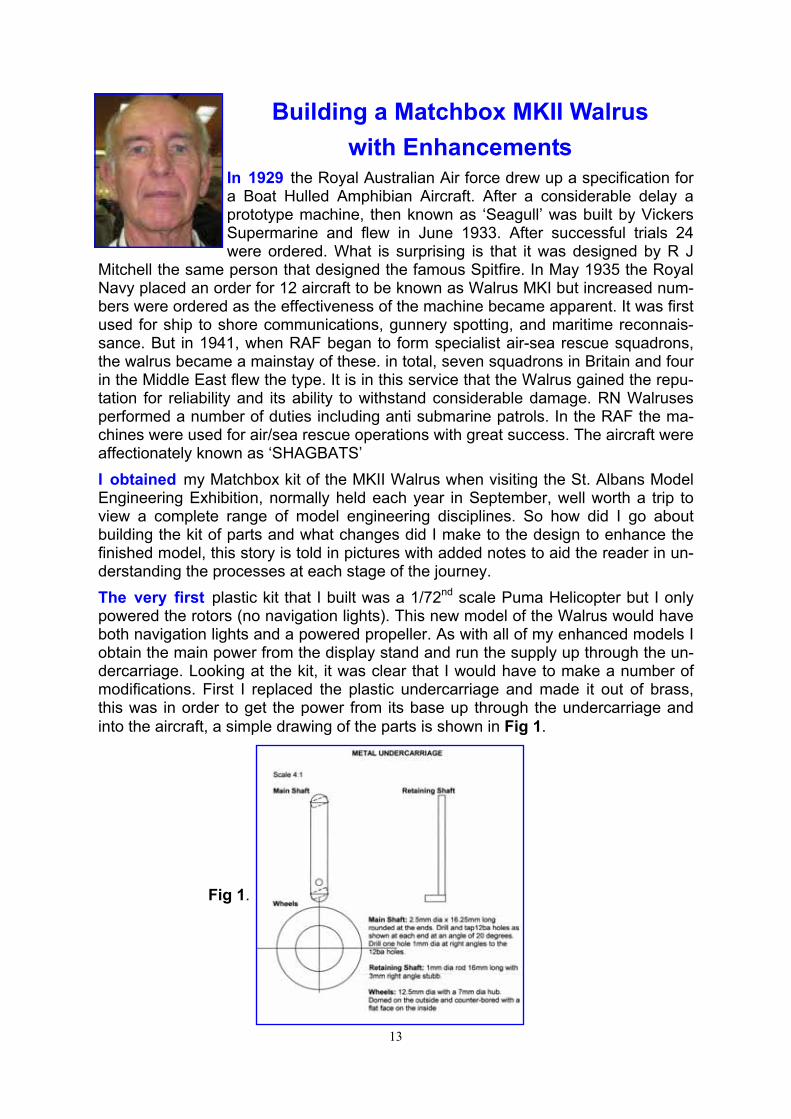
Building a Matchbox MKII Walrus with Enhancements
In 1929 the Royal Australian Air force drew up a specification for a Boat Hulled Amphibian Aircraft. After a considerable delay a prototype machine, then known as ‘Seagull’ was built by Vickers Supermarine and flew in June 1933. After successful trials 24 were ordered. What is surprising is that it was designed by R J
Mitchell the same person that designed the famous Spitfire. In May 1935 the Royal Navy placed an order for 12 aircraft to be known as Walrus MKI but increased num-bers were ordered as the effectiveness of the machine became apparent. It was first used for ship to shore communications, gunnery spotting, and maritime reconnais-sance. But in 1941, when RAF began to form specialist air-sea rescue squadrons, the walrus became a mainstay of these. in total, seven squadrons in Britain and four in the Middle East flew the type. It is in this service that the Walrus gained the repu-tation for reliability and its ability to withstand considerable damage. RN Walruses performed a number of duties including anti submarine patrols. In the RAF the ma-chines were used for air/sea rescue operations with great success. The aircraft were affectionately known as ‘SHAGBATS’ I obtained my Matchbox kit of the MKII Walrus when visiting the St. Albans Model Engineering Exhibition, normally held each year in September, well worth a trip to view a complete range of model engineering disciplines. So how did I go about building the kit of parts and what changes did I make to the design to enhance the finished model, this story is told in pictures with added notes to aid the reader in un-derstanding the processes at each stage of the journey. The very first plastic kit that I built was a 1/72nd scale Puma Helicopter but I only powered the rotors (no navigation lights). This new model of the Walrus would have both navigation lights and a powered propeller. As with all of my enhanced models I obtain the main power from the display stand and run the supply up through the un-dercarriage. Looking at the kit, it was clear that I would have to make a number of modifications. First I replaced the plastic undercarriage and made it out of brass, this was in order to get the power from its base up through the undercarriage and into the aircraft, a simple drawing of the parts is shown in Fig 1.
Fig 1.
14
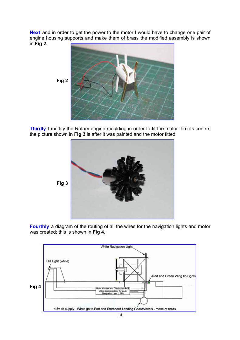
Next and in order to get the power to the motor I would have to change one pair of engine housing supports and make them of brass the modified assembly is shown in Fig 2.
Fig 2
Thirdly I modify the Rotary engine moulding in order to fit the motor thru its centre; the picture shown in Fig 3 is after it was painted and the motor fitted.
Fig 3
Fourthly a diagram of the routing of all the wires for the navigation lights and motor was created; this is shown in Fig 4.
Fig 4
15
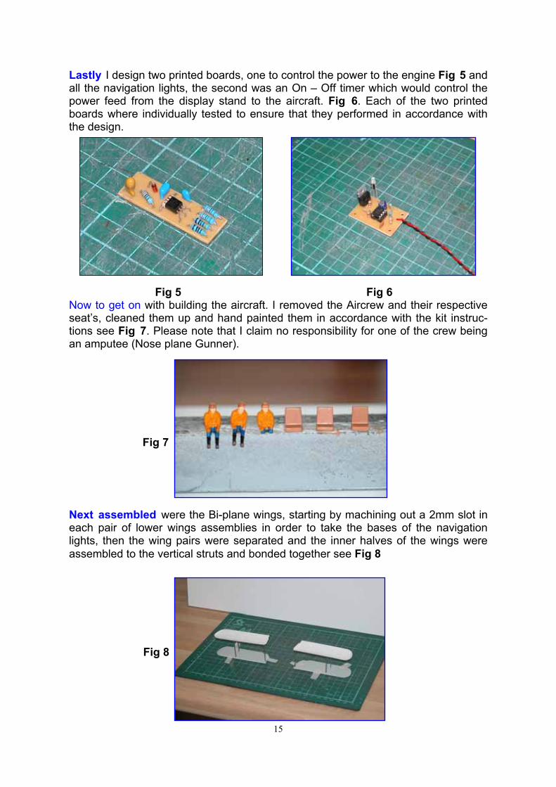
Lastly I design two printed boards, one to control the power to the engine Fig 5 and all the navigation lights, the second was an On – Off timer which would control the power feed from the display stand to the aircraft. Fig 6. Each of the two printed boards where individually tested to ensure that they performed in accordance with the design.
Fig 5 Fig 6 Now to get on with building the aircraft. I removed the Aircrew and their respective seat’s, cleaned them up and hand painted them in accordance with the kit instruc-tions see Fig 7. Please note that I claim no responsibility for one of the crew being an amputee (Nose plane Gunner).
Fig 7
Next assembled were the Bi-plane wings, starting by machining out a 2mm slot in each pair of lower wings assemblies in order to take the bases of the navigation lights, then the wing pairs were separated and the inner halves of the wings were assembled to the vertical struts and bonded together see Fig 8
Fig 8
16
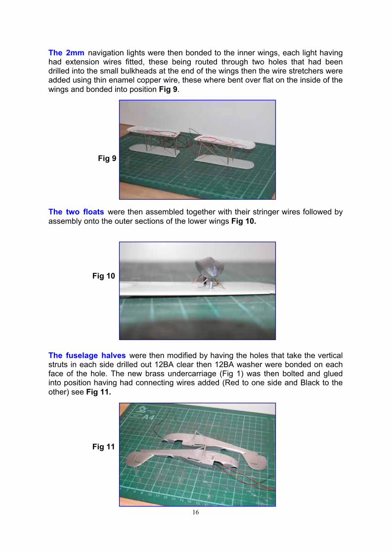
The 2mm navigation lights were then bonded to the inner wings, each light having had extension wires fitted, these being routed through two holes that had been drilled into the small bulkheads at the end of the wings then the wire stretchers were added using thin enamel copper wire, these where bent over flat on the inside of the wings and bonded into position Fig 9.
Fig 9
The two floats were then assembled together with their stringer wires followed by assembly onto the outer sections of the lower wings Fig 10.
Fig 10
The fuselage halves were then modified by having the holes that take the vertical struts in each side drilled out 12BA clear then 12BA washer were bonded on each face of the hole. The new brass undercarriage (Fig 1) was then bolted and glued into position having had connecting wires added (Red to one side and Black to the other) see Fig 11.
Fig 11
17
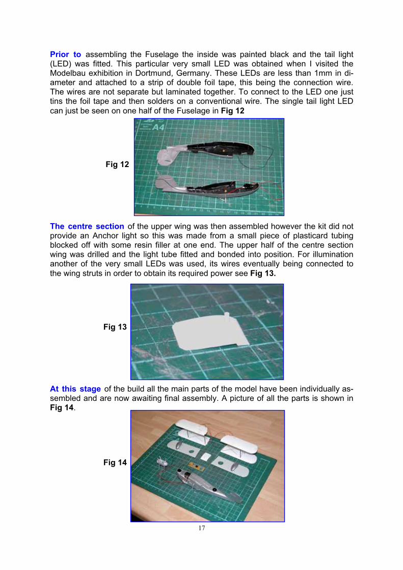
Prior to assembling the Fuselage the inside was painted black and the tail light (LED) was fitted. This particular very small LED was obtained when I visited the Modelbau exhibition in Dortmund, Germany. These LEDs are less than 1mm in di-ameter and attached to a strip of double foil tape, this being the connection wire. The wires are not separate but laminated together. To connect to the LED one just tins the foil tape and then solders on a conventional wire. The single tail light LED can just be seen on one half of the Fuselage in Fig 12
Fig 12
The centre section of the upper wing was then assembled however the kit did not provide an Anchor light so this was made from a small piece of plasticard tubing blocked off with some resin filler at one end. The upper half of the centre section wing was drilled and the light tube fitted and bonded into position. For illumination another of the very small LEDs was used, its wires eventually being connected to the wing struts in order to obtain its required power see Fig 13.
Fig 13
At this stage of the build all the main parts of the model have been individually as-sembled and are now awaiting final assembly. A picture of all the parts is shown in Fig 14.
Fig 14
18
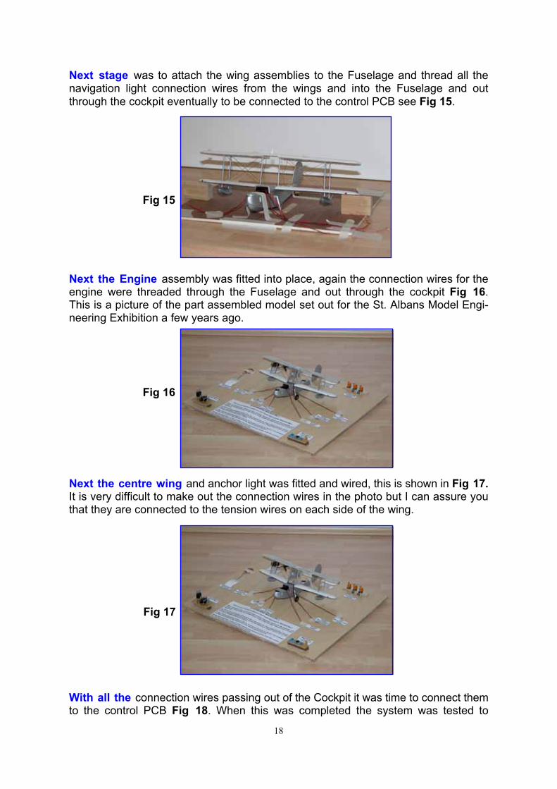
Next stage was to attach the wing assemblies to the Fuselage and thread all the navigation light connection wires from the wings and into the Fuselage and out through the cockpit eventually to be connected to the control PCB see Fig 15.
Fig 15
Next the Engine assembly was fitted into place, again the connection wires for the engine were threaded through the Fuselage and out through the cockpit Fig 16. This is a picture of the part assembled model set out for the St. Albans Model Engi-neering Exhibition a few years ago.
Fig 16
Next the centre wing and anchor light was fitted and wired, this is shown in Fig 17. It is very difficult to make out the connection wires in the photo but I can assure you that they are connected to the tension wires on each side of the wing.
Fig 17
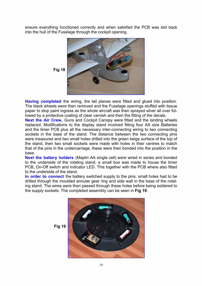
With all the connection wires passing out of the Cockpit it was time to connect them to the control PCB Fig 18. When this was completed the system was tested to
19
ensure everything functioned correctly and when satisfied the PCB was slid back into the hull of the Fuselage through the cockpit opening.
Fig 18
Having completed the wiring, the tail planes were fitted and glued into position. The black wheels were then removed and the Fuselage openings stuffed with tissue paper to stop paint ingress as the whole aircraft was then sprayed silver all over fol-lowed by a protective coating of clear varnish and then the fitting of the decals. Next the Air Crew, Guns and Cockpit Canopy were fitted and the landing wheels replaced. Modifications to the display stand involved fitting four AA size Batteries and the timer PCB plus all the necessary inter-connecting wiring to two connecting sockets in the base of the stand. The distance between the two connecting pins were measured and two small holes drilled into the green beige surface of the top of the stand, then two small sockets were made with holes in their centres to match that of the pins in the undercarriage, these were then bonded into the position in the base. Next the battery holders (Maplin AA single cell) were wired in series and bonded to the underside of the rotating stand, a small box was made to house the timer PCB, On-Off switch and indicator LED. This together with the PCB where also fitted to the underside of the stand. In order to connect the battery switched supply to the pins, small holes had to be drilled through the moulded annular gear ring and side wall in the base of the rotat-ing stand. The wires were then passed through these holes before being soldered to the supply sockets. The completed assembly can be seen in Fig 19.
Fig 19
20
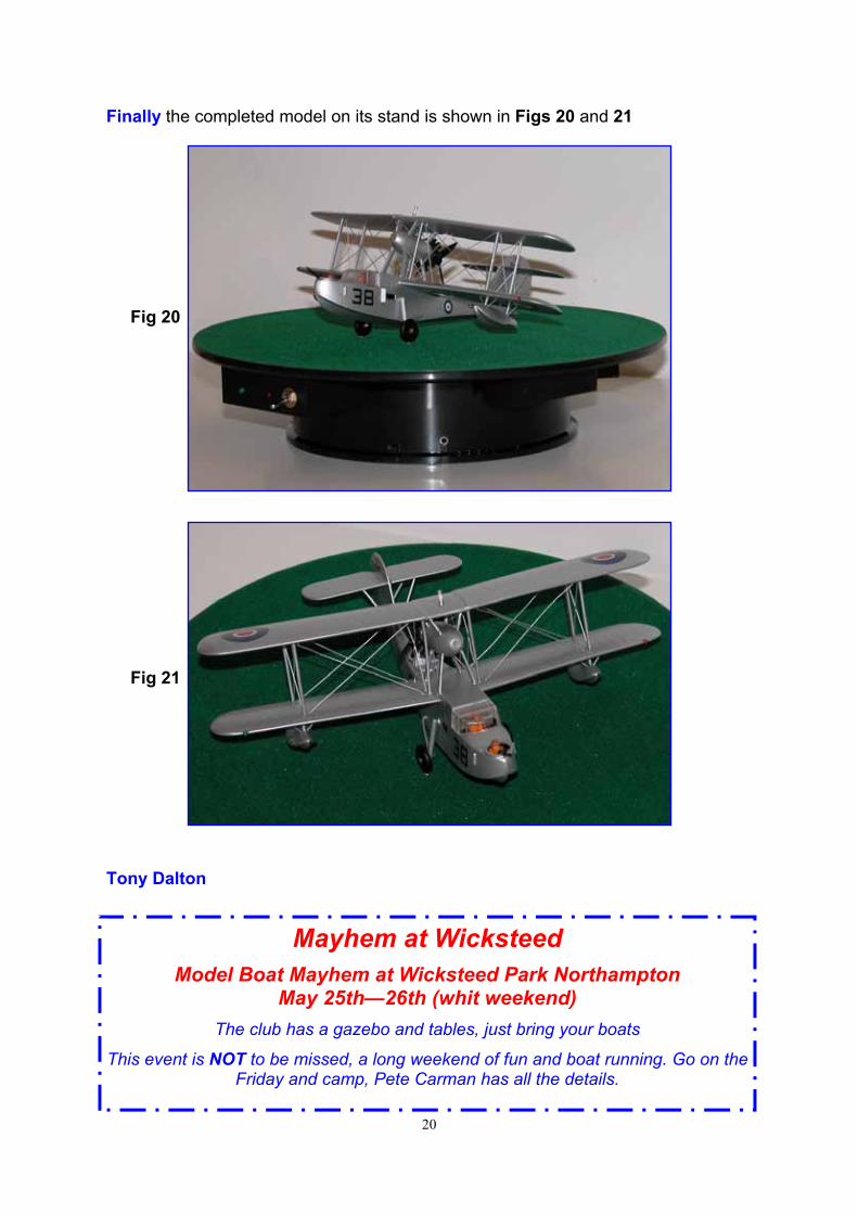
Finally the completed model on its stand is shown in Figs 20 and 21
Fig 20
Fig 21
Tony Dalton
Mayhem at Wicksteed
Model Boat Mayhem at Wicksteed Park Northampton May 25th—26th (whit weekend)
The club has a gazebo and tables, just bring your boats
This event is NOT to be missed, a long weekend of fun and boat running. Go on the Friday and camp, Pete Carman has all the details.

21
??? JUST WHAT IS PETER UP TO ??? 1) Why has Pete got the rope tied to him – So he does not get lost? 2) Pete seems to be contemplating something? 3) Goodness me I am dying for a P--s 4) Why do I need a safety rope, its only 5” deep? 5) I am sure I lost 10p here last week. 6) ????
I am sure you can improve on these suggestions E-mail me with your caption
The best will appear in the next issue
22
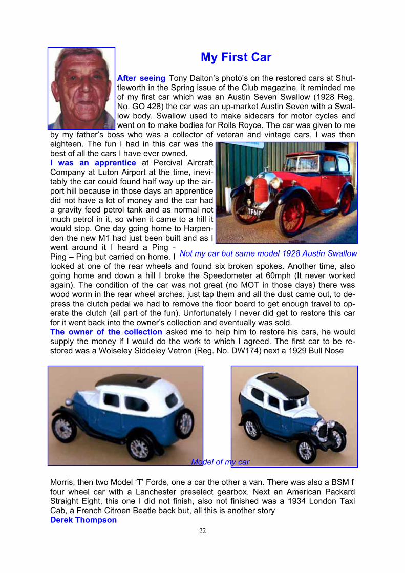
My First Car After seeing Tony Dalton’s photo’s on the restored cars at Shut-tleworth in the Spring issue of the Club magazine, it reminded me of my first car which was an Austin Seven Swallow (1928 Reg. No. GO 428) the car was an up-market Austin Seven with a Swal-low body. Swallow used to make sidecars for motor cycles and went on to make bodies for Rolls Royce. The car was given to me
by my father’s boss who was a collector of veteran and vintage cars, I was then eighteen. The fun I had in this car was the best of all the cars I have ever owned. I was an apprentice at Percival Aircraft Company at Luton Airport at the time, inevi-tably the car could found half way up the air-port hill because in those days an apprentice did not have a lot of money and the car had a gravity feed petrol tank and as normal not much petrol in it, so when it came to a hill it would stop. One day going home to Harpen-den the new M1 had just been built and as I went around it I heard a Ping - Ping – Ping but carried on home. I looked at one of the rear wheels and found six broken spokes. Another time, also going home and down a hill I broke the Speedometer at 60mph (It never worked again). The condition of the car was not great (no MOT in those days) there was wood worm in the rear wheel arches, just tap them and all the dust came out, to de-press the clutch pedal we had to remove the floor board to get enough travel to op-erate the clutch (all part of the fun). Unfortunately I never did get to restore this car for it went back into the owner’s collection and eventually was sold. The owner of the collection asked me to help him to restore his cars, he would supply the money if I would do the work to which I agreed. The first car to be re-stored was a Wolseley Siddeley Vetron (Reg. No. DW174) next a 1929 Bull Nose
Morris, then two Model ‘T’ Fords, one a car the other a van. There was also a BSM f four wheel car with a Lanchester preselect gearbox. Next an American Packard Straight Eight, this one I did not finish, also not finished was a 1934 London Taxi Cab, a French Citroen Beatle back but, all this is another story Derek Thompson
Not my car but same model 1928 Austin Swallow
Model of my car
23
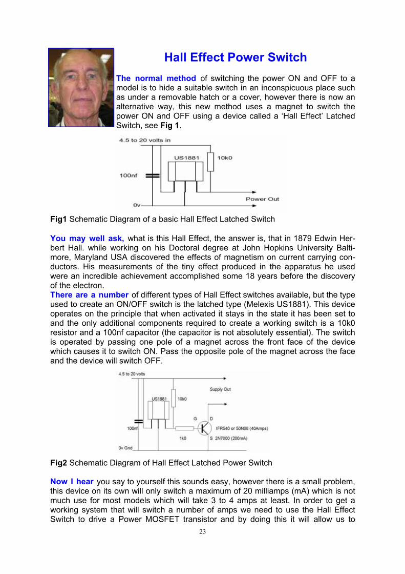
Hall Effect Power Switch The normal method of switching the power ON and OFF to a model is to hide a suitable switch in an inconspicuous place such as under a removable hatch or a cover, however there is now an alternative way, this new method uses a magnet to switch the power ON and OFF using a device called a ‘Hall Effect’ Latched Switch, see Fig 1.
You may well ask, what is this Hall Effect, the answer is, that in 1879 Edwin Her-bert Hall. while working on his Doctoral degree at John Hopkins University Balti-more, Maryland USA discovered the effects of magnetism on current carrying con-ductors. His measurements of the tiny effect produced in the apparatus he used were an incredible achievement accomplished some 18 years before the discovery of the electron. There are a number of different types of Hall Effect switches available, but the type used to create an ON/OFF switch is the latched type (Melexis US1881). This device operates on the principle that when activated it stays in the state it has been set to and the only additional components required to create a working switch is a 10k0 resistor and a 100nf capacitor (the capacitor is not absolutely essential). The switch is operated by passing one pole of a magnet across the front face of the device which causes it to switch ON. Pass the opposite pole of the magnet across the face and the device will switch OFF.
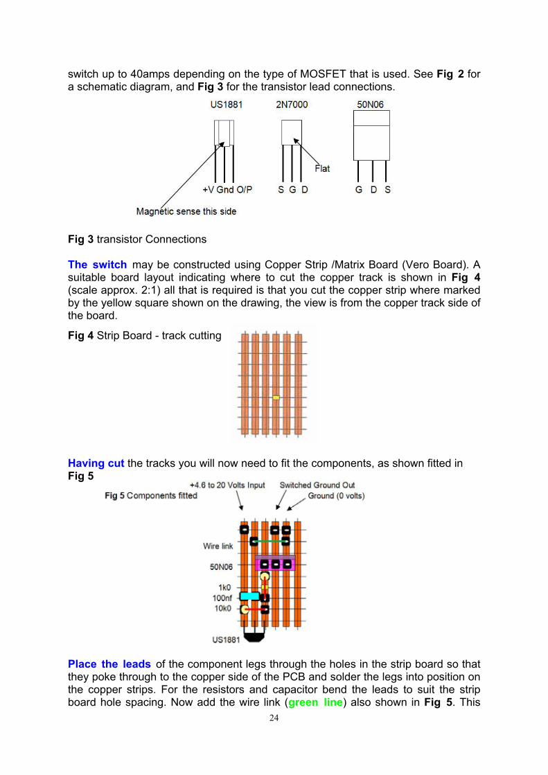
Now I hear you say to yourself this sounds easy, however there is a small problem, this device on its own will only switch a maximum of 20 milliamps (mA) which is not much use for most models which will take 3 to 4 amps at least. In order to get a working system that will switch a number of amps we need to use the Hall Effect Switch to drive a Power MOSFET transistor and by doing this it will allow us to
Fig1 Schematic Diagram of a basic Hall Effect Latched Switch
Fig2 Schematic Diagram of Hall Effect Latched Power Switch
24
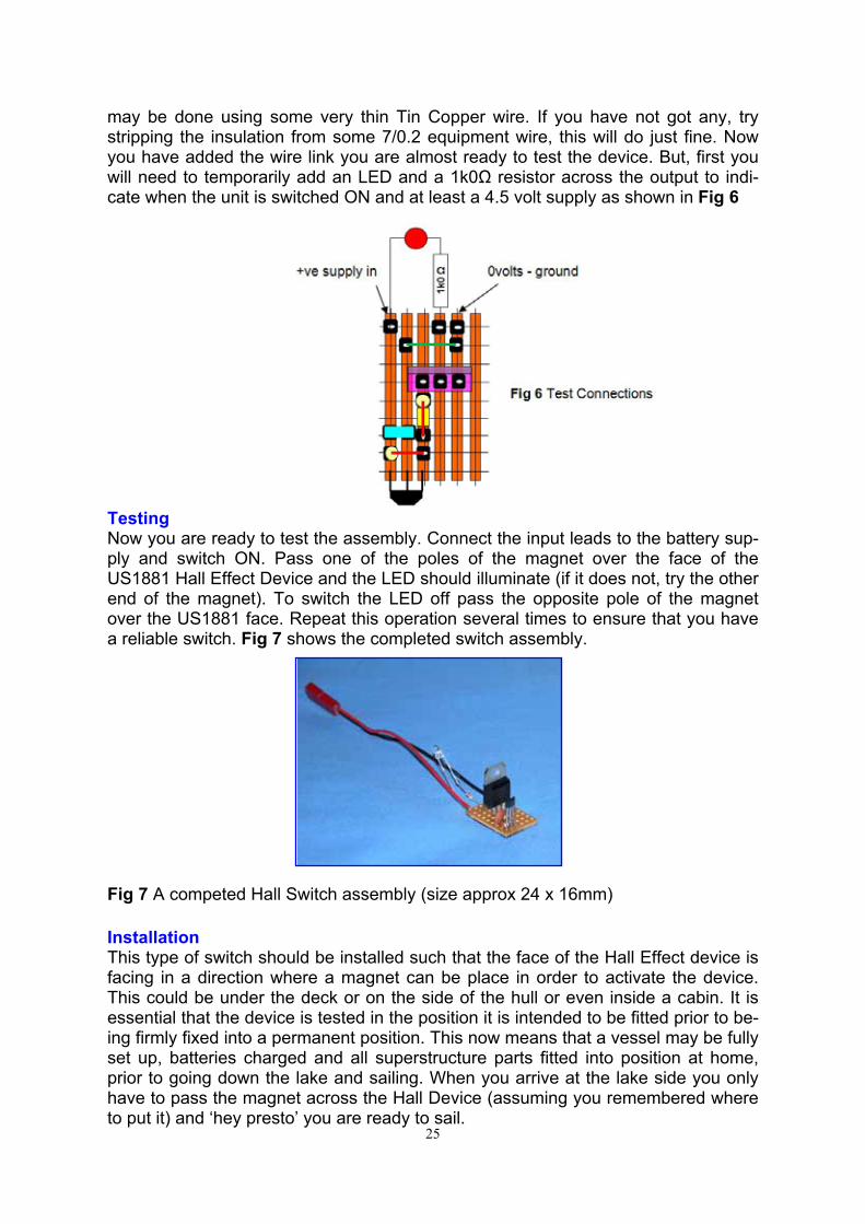
switch up to 40amps depending on the type of MOSFET that is used. See Fig 2 for a schematic diagram, and Fig 3 for the transistor lead connections. Fig 3 transistor Connections The switch may be constructed using Copper Strip /Matrix Board (Vero Board). A suitable board layout indicating where to cut the copper track is shown in Fig 4 (scale approx. 2:1) all that is required is that you cut the copper strip where marked by the yellow square shown on the drawing, the view is from the copper track side of the board.
Fig 4 Strip Board - track cutting Having cut the tracks you will now need to fit the components, as shown fitted in Fig 5
Place the leads of the component legs through the holes in the strip board so that they poke through to the copper side of the PCB and solder the legs into position on the copper strips. For the resistors and capacitor bend the leads to suit the strip board hole spacing. Now add the wire link (green line) also shown in Fig 5. This
25
may be done using some very thin Tin Copper wire. If you have not got any, try stripping the insulation from some 7/0.2 equipment wire, this will do just fine. Now you have added the wire link you are almost ready to test the device. But, first you will need to temporarily add an LED and a 1k0Ω resistor across the output to indi-cate when the unit is switched ON and at least a 4.5 volt supply as shown in Fig 6
Testing Now you are ready to test the assembly. Connect the input leads to the battery sup-ply and switch ON. Pass one of the poles of the magnet over the face of the US1881 Hall Effect Device and the LED should illuminate (if it does not, try the other end of the magnet). To switch the LED off pass the opposite pole of the magnet over the US1881 face. Repeat this operation several times to ensure that you have a reliable switch. Fig 7 shows the completed switch assembly.
Fig 7 A competed Hall Switch assembly (size approx 24 x 16mm) Installation This type of switch should be installed such that the face of the Hall Effect device is facing in a direction where a magnet can be place in order to activate the device. This could be under the deck or on the side of the hull or even inside a cabin. It is essential that the device is tested in the position it is intended to be fitted prior to be-ing firmly fixed into a permanent position. This now means that a vessel may be fully set up, batteries charged and all superstructure parts fitted into position at home, prior to going down the lake and sailing. When you arrive at the lake side you only have to pass the magnet across the Hall Device (assuming you remembered where to put it) and ‘hey presto’ you are ready to sail.
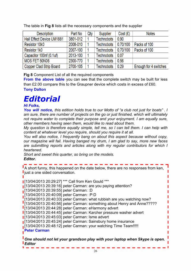
The table in Fig 8 lists all the necessary components and the supplier
Fig 8 Component List of all the required components From the above table you can see that the complete switch may be built for less than £2.00 compare this to the Graupner device which costs in excess of £60. Tony Dalton
Editorial Hi Folks, You will notice, this edition holds true to our Motto of “a club not just for boats” . I am sure, there are number of projects on the go or just finished, which will ultimately not require water to complete their purpose and your enjoyment. I am equally sure, other members having seen them, would like to read about them. My question is therefore equally simple, tell me, so I can tell them. I can help with content at whatever level you require, should you require it at all. You will also notice, I frequently bang on about this aspect because without copy, our magazine will fail. Having banged my drum, I am glad to say, more new faces are submitting reports and articles along with my regular contributors for which I heartened. Short and sweet this quarter, so bring on the models. Editor.
26
A short funny, this happened on the date below, there are no responses from ken, just a one sided conversation. [13/04/2013 20:29:27] *** Call from Ken Gould *** [13/04/2013 20:39:16] peter Carman: are you paying attention? [13/04/2013 20:39:55] peter Carman: :D [13/04/2013 20:40:09] peter Carman: :P:D [13/04/2013 20:40:33] peter Carman: what rubbish are you watching now? [13/04/2013 20:40:56] peter Carman: something about Henry and Anne????? [13/04/2013 20:44:28] peter Carman: eHarmony advert [13/04/2013 20:44:45] peter Carman: Karcher pressure washer advert [13/04/2013 20:45:03] peter Carman: Isme advert [13/04/2013 20:45:24] peter Carman: Sainsbury home insurance [13/04/2013 20:48:12] peter Carman: your watching Time Team!!!!! Peter Carman One should not let your grandson play with your laptop when Skype is open. Editor
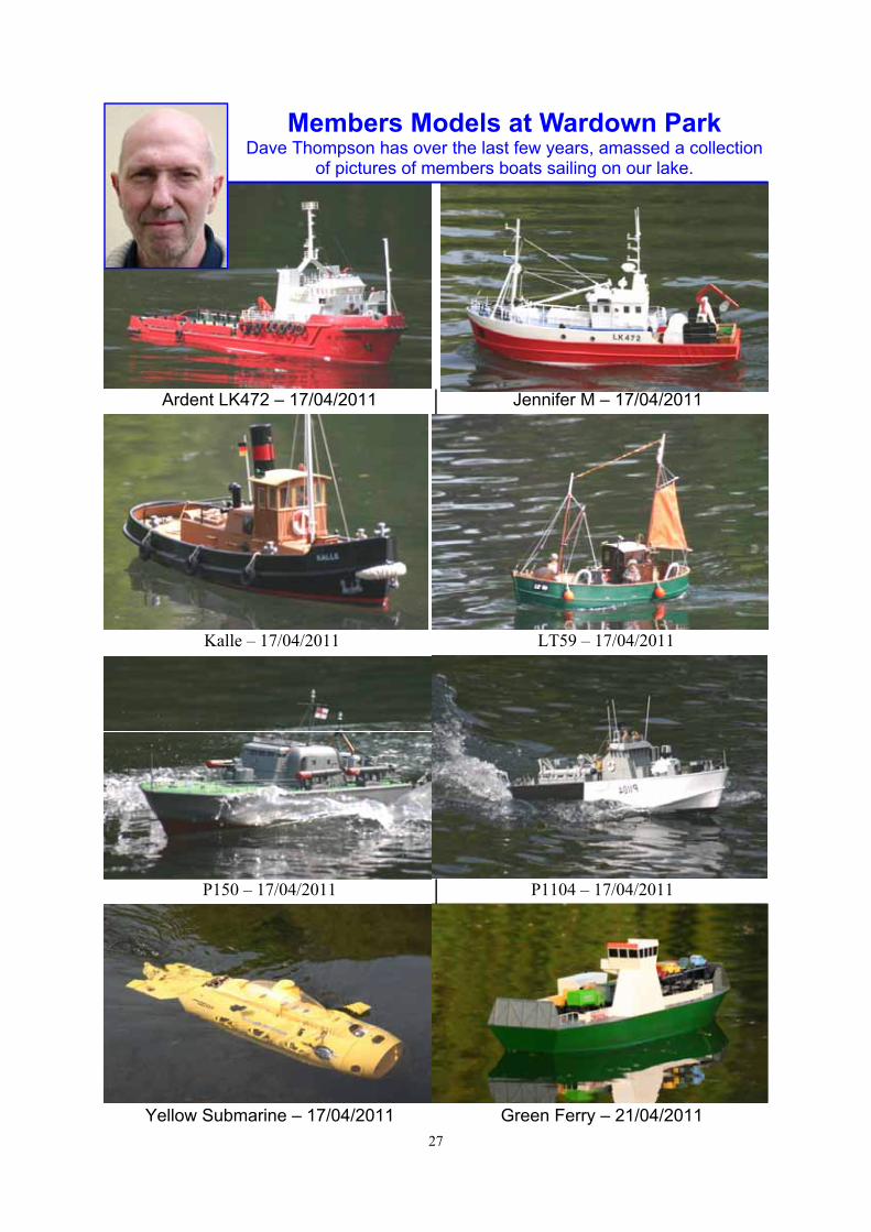
Members Models at Wardown Park Dave Thompson has over the last few years, amassed a collection
of pictures of members boats sailing on our lake.
Ardent LK472 – 17/04/2011 Jennifer M – 17/04/2011
27
Kalle – 17/04/2011 LT59 – 17/04/2011
P150 – 17/04/2011 P1104 – 17/04/2011
Yellow Submarine – 17/04/2011 Green Ferry – 21/04/2011
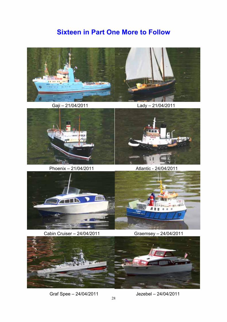
Sixteen in Part One More to Follow
28
Gaji – 21/04/2011 Lady – 21/04/2011
Phoenix – 21/04/2011 Atlantic - 24/04/2011
Cabin Cruiser – 24/04/2011 Graemsey – 24/04/2011
Graf Spee – 24/04/2011 Jezebel – 24/04/2011
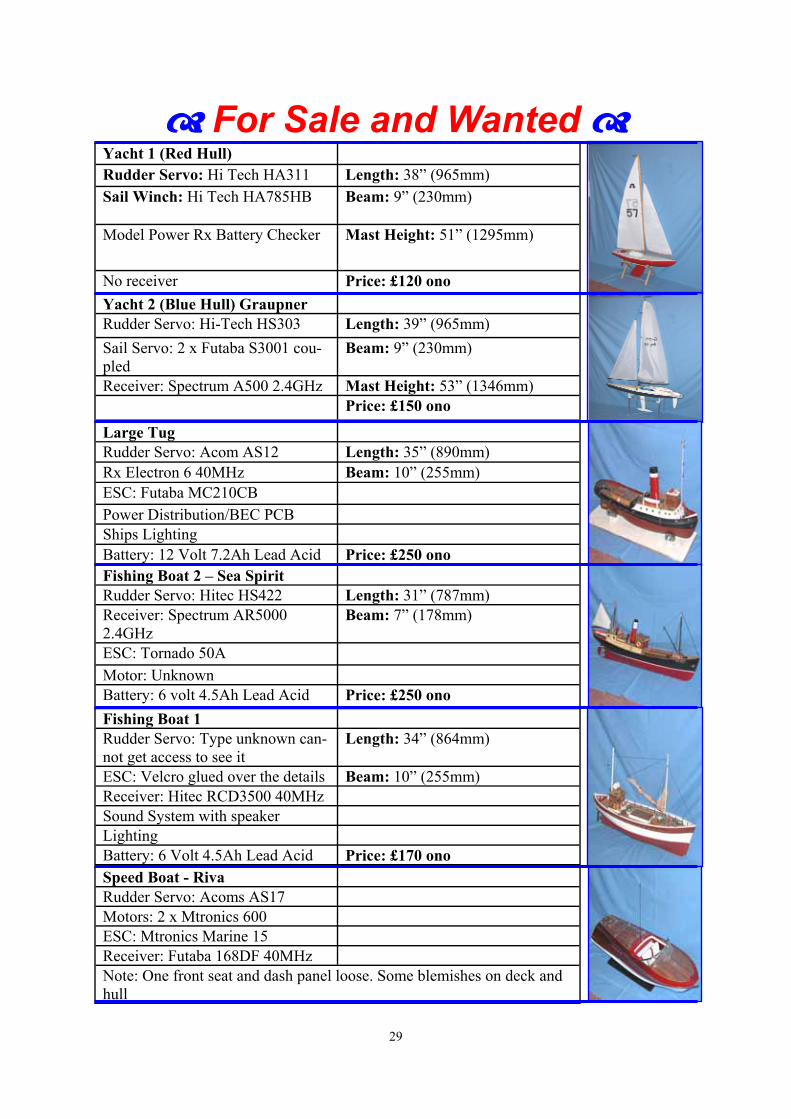
For Sale and Wanted
29
Yacht 1 (Red Hull) Rudder Servo: Hi Tech HA311 Length: 38” (965mm)
Sail Winch: Hi Tech HA785HB Beam: 9” (230mm)
Model Power Rx Battery Checker Mast Height: 51” (1295mm)
No receiver Price: £120 ono
Yacht 2 (Blue Hull) Graupner Rudder Servo: Hi-Tech HS303 Length: 39” (965mm)
Sail Servo: 2 x Futaba S3001 cou-pled
Beam: 9” (230mm)
Receiver: Spectrum A500 2.4GHz Mast Height: 53” (1346mm) Price: £150 ono
Large Tug Rudder Servo: Acom AS12 Length: 35” (890mm) Rx Electron 6 40MHz Beam: 10” (255mm) ESC: Futaba MC210CB Power Distribution/BEC PCB Ships Lighting Battery: 12 Volt 7.2Ah Lead Acid Price: £250 ono Fishing Boat 2 – Sea Spirit Rudder Servo: Hitec HS422 Length: 31” (787mm) Receiver: Spectrum AR5000 2.4GHz
Beam: 7” (178mm)
ESC: Tornado 50A Motor: Unknown Battery: 6 volt 4.5Ah Lead Acid Price: £250 ono
Fishing Boat 1 Rudder Servo: Type unknown can-not get access to see it
Length: 34” (864mm)
ESC: Velcro glued over the details Beam: 10” (255mm) Receiver: Hitec RCD3500 40MHz Sound System with speaker Lighting Battery: 6 Volt 4.5Ah Lead Acid Price: £170 ono
Speed Boat - Riva Rudder Servo: Acoms AS17 Motors: 2 x Mtronics 600 ESC: Mtronics Marine 15 Receiver: Futaba 168DF 40MHz Note: One front seat and dash panel loose. Some blemishes on deck and hull
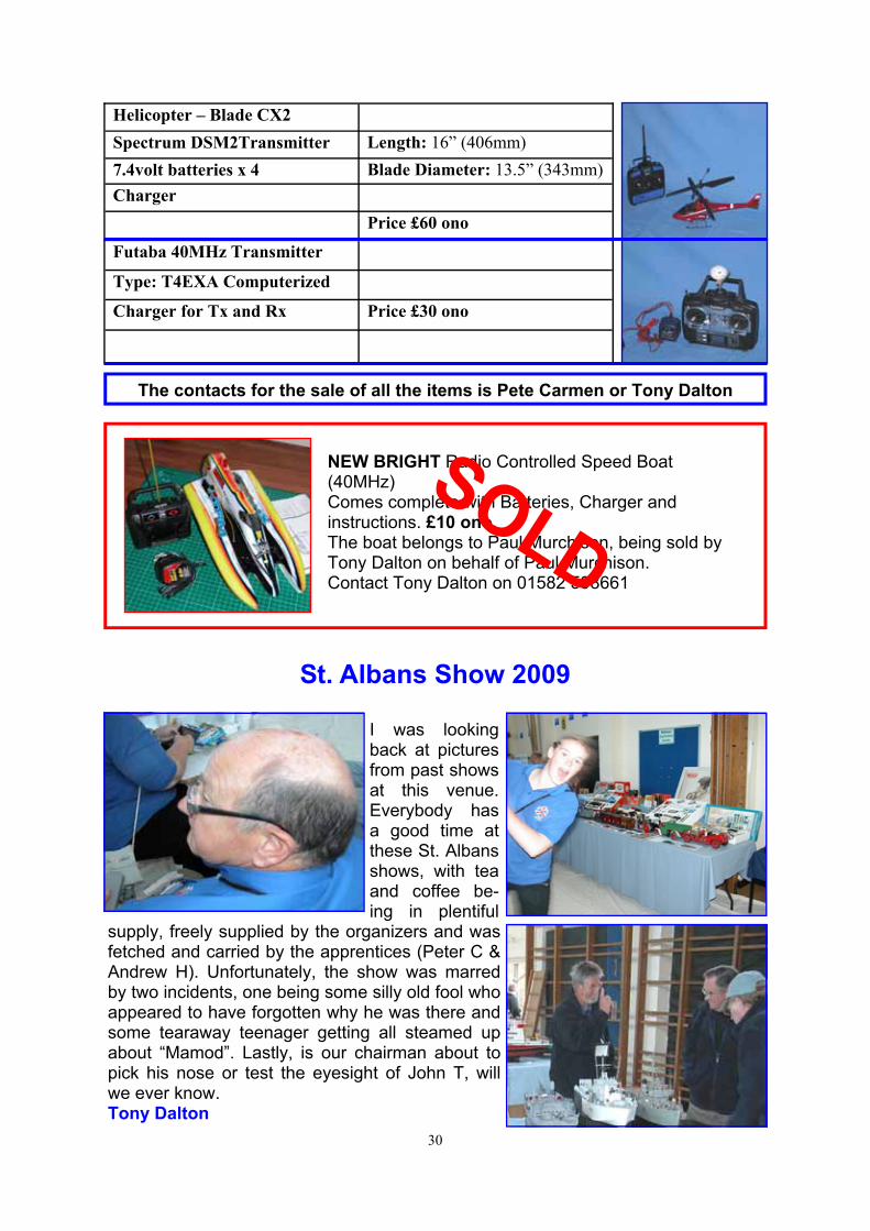
Helicopter – Blade CX2 Spectrum DSM2Transmitter Length: 16” (406mm)
7.4volt batteries x 4 Blade Diameter: 13.5” (343mm)
Charger Price £60 ono
Futaba 40MHz Transmitter
Type: T4EXA Computerized
Charger for Tx and Rx Price £30 ono
The contacts for the sale of all the items is Pete Carmen or Tony Dalton
30
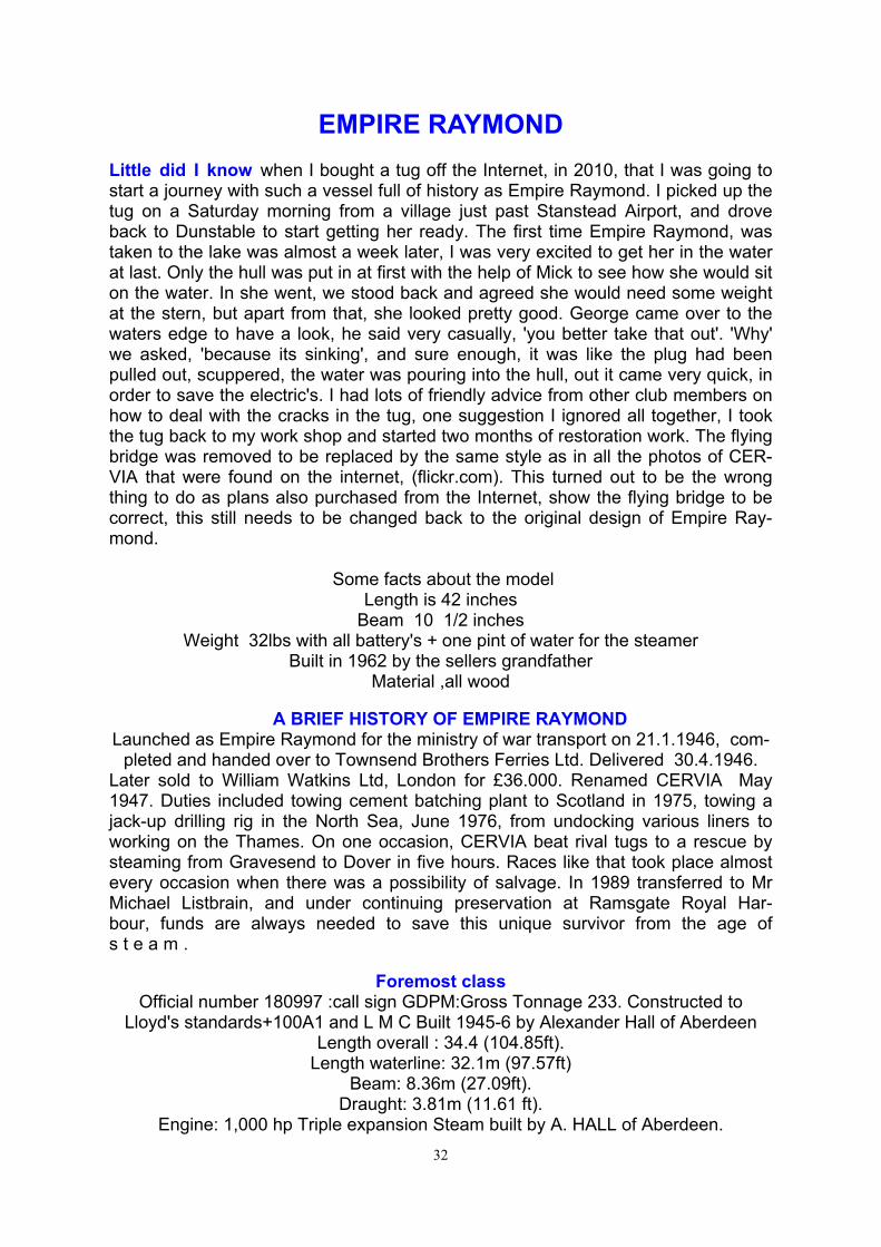
St. Albans Show 2009
I was looking back at pictures from past shows at this venue. Everybody has a good time at these St. Albans shows, with tea and coffee be-ing in plentiful
supply, freely supplied by the organizers and was fetched and carried by the apprentices (Peter C & Andrew H). Unfortunately, the show was marred by two incidents, one being some silly old fool who appeared to have forgotten why he was there and some tearaway teenager getting all steamed up about “Mamod”. Lastly, is our chairman about to pick his nose or test the eyesight of John T, will we ever know. Tony Dalton
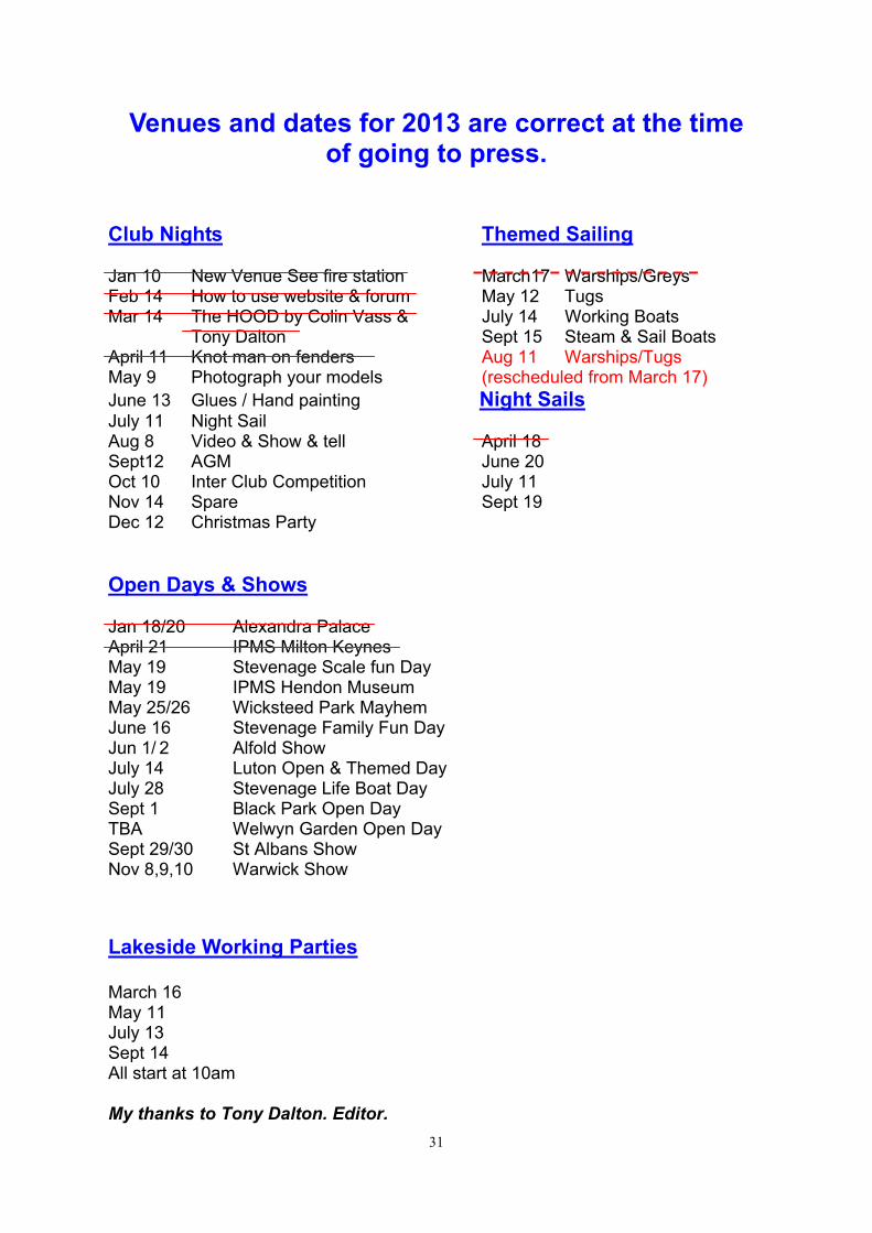
NEW BRIGHT Radio Controlled Speed Boat (40MHz) Comes complete with Batteries, Charger and instructions. £10 ono. The boat belongs to Paul Murchison, being sold by Tony Dalton on behalf of Paul Murchison. Contact Tony Dalton on 01582 598661
SOLD
31
Venues and dates for 2013 are correct at the time of going to press.
Club Nights Themed Sailing Jan 10 New Venue See fire station March17 Warships/Greys Feb 14 How to use website & forum May 12 Tugs Mar 14 The HOOD by Colin Vass & July 14 Working Boats Tony Dalton Sept 15 Steam & Sail Boats April 11 Knot man on fenders Aug 11 Warships/Tugs May 9 Photograph your models (rescheduled from March 17) June 13 Glues / Hand painting Night Sails July 11 Night Sail Aug 8 Video & Show & tell April 18 Sept12 AGM June 20 Oct 10 Inter Club Competition July 11 Nov 14 Spare Sept 19 Dec 12 Christmas Party Open Days & Shows Jan 18/20 Alexandra Palace April 21 IPMS Milton Keynes May 19 Stevenage Scale fun Day May 19 IPMS Hendon Museum May 25/26 Wicksteed Park Mayhem June 16 Stevenage Family Fun Day Jun 1/ 2 Alfold Show July 14 Luton Open & Themed Day July 28 Stevenage Life Boat Day Sept 1 Black Park Open Day TBA Welwyn Garden Open Day Sept 29/30 St Albans Show Nov 8,9,10 Warwick Show
Lakeside Working Parties March 16 May 11 July 13 Sept 14 All start at 10am My thanks to Tony Dalton. Editor.
32
EMPIRE RAYMOND Little did I know when I bought a tug off the Internet, in 2010, that I was going to start a journey with such a vessel full of history as Empire Raymond. I picked up the tug on a Saturday morning from a village just past Stanstead Airport, and drove back to Dunstable to start getting her ready. The first time Empire Raymond, was taken to the lake was almost a week later, I was very excited to get her in the water at last. Only the hull was put in at first with the help of Mick to see how she would sit on the water. In she went, we stood back and agreed she would need some weight at the stern, but apart from that, she looked pretty good. George came over to the waters edge to have a look, he said very casually, 'you better take that out'. 'Why' we asked, 'because its sinking', and sure enough, it was like the plug had been pulled out, scuppered, the water was pouring into the hull, out it came very quick, in order to save the electric's. I had lots of friendly advice from other club members on how to deal with the cracks in the tug, one suggestion I ignored all together, I took the tug back to my work shop and started two months of restoration work. The flying bridge was removed to be replaced by the same style as in all the photos of CER-VIA that were found on the internet, (flickr.com). This turned out to be the wrong thing to do as plans also purchased from the Internet, show the flying bridge to be correct, this still needs to be changed back to the original design of Empire Ray-mond.
Some facts about the model
Length is 42 inches Beam 10 1/2 inches
Weight 32lbs with all battery's + one pint of water for the steamer Built in 1962 by the sellers grandfather
Material ,all wood
A BRIEF HISTORY OF EMPIRE RAYMOND Launched as Empire Raymond for the ministry of war transport on 21.1.1946, com-
pleted and handed over to Townsend Brothers Ferries Ltd. Delivered 30.4.1946. Later sold to William Watkins Ltd, London for £36.000. Renamed CERVIA May 1947. Duties included towing cement batching plant to Scotland in 1975, towing a jack-up drilling rig in the North Sea, June 1976, from undocking various liners to working on the Thames. On one occasion, CERVIA beat rival tugs to a rescue by steaming from Gravesend to Dover in five hours. Races like that took place almost every occasion when there was a possibility of salvage. In 1989 transferred to Mr Michael Listbrain, and under continuing preservation at Ramsgate Royal Har-bour, funds are always needed to save this unique survivor from the age of s t e a m .
Foremost class Official number 180997 :call sign GDPM:Gross Tonnage 233. Constructed to
Lloyd's standards+100A1 and L M C Built 1945-6 by Alexander Hall of Aberdeen Length overall : 34.4 (104.85ft).
Length waterline: 32.1m (97.57ft) Beam: 8.36m (27.09ft).
Draught: 3.81m (11.61 ft). Engine: 1,000 hp Triple expansion Steam built by A. HALL of Aberdeen.
33
Boiler Pressure 1.31 N/mm 2 (190 p.s.i.) Generator: 10 kw 110v DC Generator. Fuel Capacity: 79 tons Water Ballast: 29tons.Three watertight Bulkheads.
Empire Raymond's colours are those of her first company, WILLIAM WATKINS Ltd :
Black Funnel with red mid-band, brown and white superstructure, Black hull with white lines.
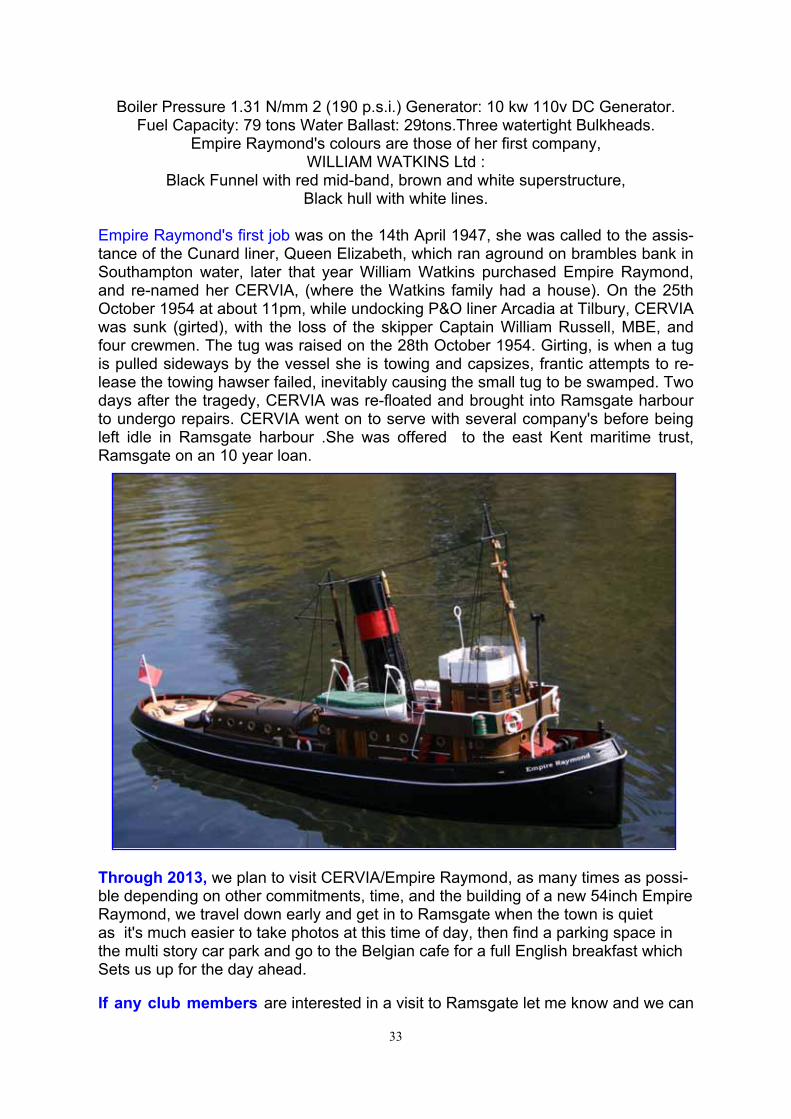
Empire Raymond's first job was on the 14th April 1947, she was called to the assis-tance of the Cunard liner, Queen Elizabeth, which ran aground on brambles bank in Southampton water, later that year William Watkins purchased Empire Raymond, and re-named her CERVIA, (where the Watkins family had a house). On the 25th October 1954 at about 11pm, while undocking P&O liner Arcadia at Tilbury, CERVIA was sunk (girted), with the loss of the skipper Captain William Russell, MBE, and four crewmen. The tug was raised on the 28th October 1954. Girting, is when a tug is pulled sideways by the vessel she is towing and capsizes, frantic attempts to re-lease the towing hawser failed, inevitably causing the small tug to be swamped. Two days after the tragedy, CERVIA was re-floated and brought into Ramsgate harbour to undergo repairs. CERVIA went on to serve with several company's before being left idle in Ramsgate harbour .She was offered to the east Kent maritime trust, Ramsgate on an 10 year loan.
Through 2013, we plan to visit CERVIA/Empire Raymond, as many times as possi-ble depending on other commitments, time, and the building of a new 54inch Empire Raymond, we travel down early and get in to Ramsgate when the town is quiet as it's much easier to take photos at this time of day, then find a parking space in the multi story car park and go to the Belgian cafe for a full English breakfast which Sets us up for the day ahead. If any club members are interested in a visit to Ramsgate let me know and we can
34
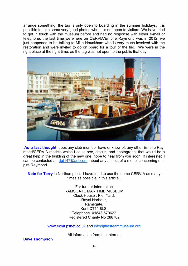
arrange something, the tug is only open to boarding in the summer holidays, It is possible to take some very good photos when it's not open to visitors. We have tried to get in touch with the museum before and had no response with either e-mail or telephone, the last time we where on CERVIA/Empire Raymond was in 2012, we just happened to be talking to Mike Houckham who is very much involved with the restoration and were invited to go on board for a tour of the tug. We were in the right place at the right time, as the tug was not open to the public that day.
As a last thought, does any club member have or know of, any other Empire Ray-mond/CERVIA models which I could see, discus, and photograph, that would be a great help in the building of the new one, hope to hear from you soon. If interested I can be contacted at, [email protected], about any aspect of a model concerning em-pire Raymond
Note for Terry in Northampton, I have tried to use the name CERVIA as many
times as possible in this article .
For further information RAMSGATE MARITIME MUSEUM
Clock House , Pier Yard, Royal Harbour,
Ramsgate, Kent CT11 8LS.
Telephone 01843 570622 Registered Charity No 288702
www.ekmt.psnet.co.uk and [email protected]
All information from the Internet
Dave Thompson