Embed Size (px)
Citation preview
© 2011 Trane
NOTICE: Since the manufacturer has a policy of continuous product and product data improvement, it reserves the right to change design and specifications without notice.
Hyperion Field Reference Data TAM7
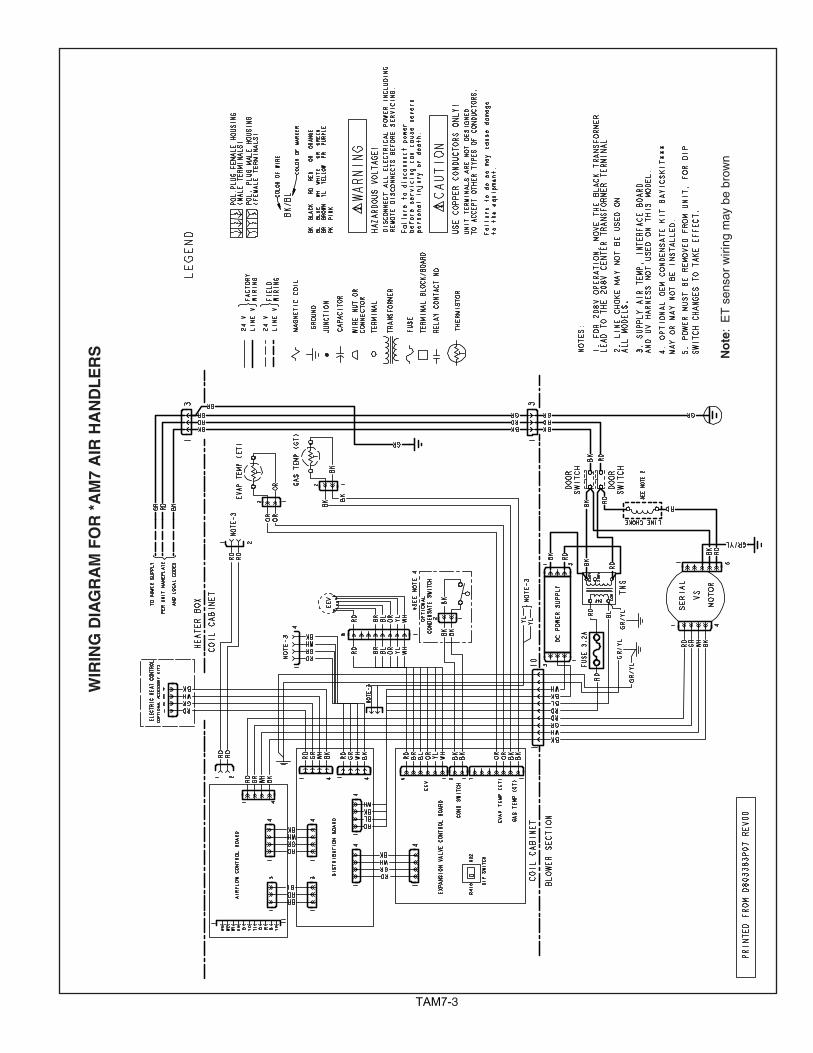
IMPORTANT --- This document contains a wiring diagram and service information. This is customer property and is to remain with this unit. Please return to service information pack upon completion of work.
HAZARDOUS VOLTAGE - DISCONNECT POWER BEFORE SERVICINGWARNING:For use with BAYEV or BAYW series heaters ONLY
� WARNING!SAFETY HAZARD! This information is intended for use by individuals possessing adequate backgrounds of electrical and mechanical experience. Any attempt to repair a central air condition-ing product may result in personal injury and/or property damage. The manufacture or seller cannot be responsible for the interpreta-tion of this information, nor can it assume any liability in connection with its use.
PRESSURIZED REFRIGERANT! SYSTEM CONTAINS OIL AND REFRIGERANT UNDER HIGH PRESSURE. RECOVER REFRIGERANT TO RELIEVE PRESSURE BEFORE OPENING THE SYSTEM.
DO NOT USE NON-APPROVED REFRIGERANTS OR REFRIGERANT SUBSTITUTES OR REFRIGERANT ADDITIVES.
� WARNING!
LIVE ELECTRICAL COMPONENTS! During instal-lation, testing, servicing, and troubleshooting of this product, it may be necessary to work with live electrical components. Failure to fol-low all electrical safety precautions when exposed to live electrical components could result in death or serious injury.
� WARNING! Note: This unit is certified to UL 1995. The interior cabinet wall meets the following: - UL94-5VA Flame Class Listed - UL723 Steiner Tunnel Listed for 25/50 Flame/Smoke - UL746C Listed for Exposure to Ultraviolet Light, Water Exposure and Immersion
Table of ContentsProduct Specifications. .................................................................................................... 2Wiring Diagram. ............................................................................................................... 3Sequence of Operation. ................................................................................................... 4Control Layout - Refrigerant Dip Switches....................................................................... 7Airflow Performance. ...................................................................................................... 10Heater Attribute Data. .................................................................................................... 16Control Layout - LEDs. ................................................................................................... 19EEV Test Procedures. .................................................................................................... 24EVC Thermal Resistance and Voltage Table. ................................................................ 25Troubleshooting. ............................................................................................................ 26
* May be "A" or "T"
Air Handler - ConvertibleModels: Series 7 Air Handlers 2-5 Ton*AM7A0A24H21SA, *AM7A0B30H21SA*AM7A0C36H31SA, *AM7A0C42H31SA*AM7A0C48H41SA, *AM7A0C60H51SA
TAM72
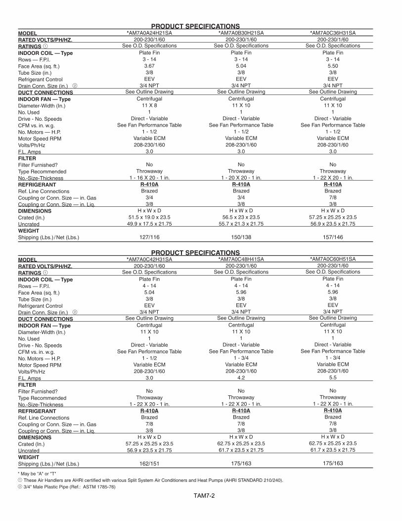
PRODUCT SPECIFICATIONSMODEL RATED VOLTS/PH/HZ. RATINGS 1INDOOR COIL — Type Rows — F.P.I. Face Area (sq. ft.) Tube Size (in.) Refrigerant Control Drain Conn. Size (in.) 2DUCT CONNECTIONS INDOOR FAN — Type Diameter-Width (In.) No. Used Drive - No. Speeds CFM vs. in. w.g. No. Motors — H.P. Motor Speed RPM Volts/Ph/Hz F.L. Amps FILTERFilter Furnished? Type Recommended No.-Size-Thickness REFRIGERANT Ref. Line Connections Coupling or Conn. Size — in. Gas Coupling or Conn. Size — in. Liq. DIMENSIONS Crated (In.) Uncrated WEIGHTShipping (Lbs.) / Net (Lbs.)
*AM7A0A24H21SA200-230/1/60
See O.D. SpecificationsPlate Fin
3 - 143.673/8
EEV 3/4 NPT
See Outline DrawingCentrifugal
11 X 8 1
Direct - Variable See Fan Performance Table
1 - 1/2Variable ECM208-230/1/60
3.0
NoThrowaway
1 - 16 X 20 - 1 in.R-410ABrazed
3/43/8
H x W x D51.5 x 19.0 x 23.5 49.9 x 17.5 x 21.75
127/116
*AM7A0B30H21SA200-230/1/60
See O.D. SpecificationsPlate Fin
3 - 145.043/8
EEV 3/4 NPT
See Outline DrawingCentrifugal
11 X 10 1
Direct - Variable See Fan Performance Table
1 - 1/2Variable ECM208-230/1/60
3.0
NoThrowaway
1 - 20 X 20 - 1 in.R-410ABrazed
3/43/8
H x W x D56.5 x 23 x 23.5
55.7 x 21.3 x 21.75
150/138
*AM7A0C36H31SA200-230/1/60
See O.D. SpecificationsPlate Fin
3 - 145.503/8
EEV 3/4 NPT
See Outline DrawingCentrifugal
11 X 10 1
Direct - Variable See Fan Performance Table
1 - 1/2Variable ECM208-230/1/60
3.0
NoThrowaway
1 - 22 X 20 - 1 in.R-410ABrazed
7/83/8
H x W x D57.25 x 25.25 x 23.5 56.9 x 23.5 x 21.75
157/146
PRODUCT SPECIFICATIONSMODEL RATED VOLTS/PH/HZ. RATINGS 1INDOOR COIL — Type Rows — F.P.I. Face Area (sq. ft.) Tube Size (in.) Refrigerant Control Drain Conn. Size (in.) 2DUCT CONNECTIONS INDOOR FAN — Type Diameter-Width (In.) No. Used Drive - No. Speeds CFM vs. in. w.g. No. Motors — H.P. Motor Speed RPM Volts/Ph/Hz F.L. Amps FILTERFilter Furnished? Type Recommended No.-Size-Thickness REFRIGERANT Ref. Line Connections Coupling or Conn. Size — in. Gas Coupling or Conn. Size — in. Liq. DIMENSIONS Crated (In.) Uncrated WEIGHTShipping (Lbs.) / Net (Lbs.)
*AM7A0C42H31SA200-230/1/60
See O.D. SpecificationsPlate Fin
4 - 145.043/8
EEV 3/4 NPT
See Outline DrawingCentrifugal
11 X 10 1
Direct - Variable See Fan Performance Table
1 - 1/2Variable ECM208-230/1/60
3.0
NoThrowaway
1 - 22 X 20 - 1 in.R-410ABrazed
7/83/8
H x W x D57.25 x 25.25 x 23.5 56.9 x 23.5 x 21.75
162/151
*AM7A0C60H51SA200-230/1/60
See O.D. SpecificationsPlate Fin
4 - 145.963/8
EEV 3/4 NPT
See Outline DrawingCentrifugal
11 X 10 1
Direct - Variable See Fan Performance Table
1 - 3/4Variable ECM208-230/1/60
5.5
NoThrowaway
1 - 22 X 20 - 1 in.R-410ABrazed
7/83/8
H x W x D62.75 x 25.25 x 23.5 61.7 x 23.5 x 21.75
175/163
*AM7A0C48H41SA200-230/1/60
See O.D. SpecificationsPlate Fin
4 - 145.963/8
EEV 3/4 NPT
See Outline DrawingCentrifugal
11 X 10 1
Direct - Variable See Fan Performance Table
1 - 3/4Variable ECM208-230/1/60
4.2
NoThrowaway
1 - 22 X 20 - 1 in.R-410ABrazed
7/83/8
H x W x D62.75 x 25.25 x 23.5 61.7 x 23.5 x 21.75
175/163
* May be "A" or "T"1 These Air Handlers are AHRI certified with various Split System Air Conditioners and Heat Pumps (AHRI STANDARD 210/240). 2 3/4" Male Plastic Pipe (Ref.: ASTM 1785-76)
TAM73
WIR
ING
DIA
GR
AM
FO
R *
AM
7 A
IR H
AN
DL
ER
S No
te:
ET
sen
sor
wiri
ng m
ay b
e br
own
TAM74
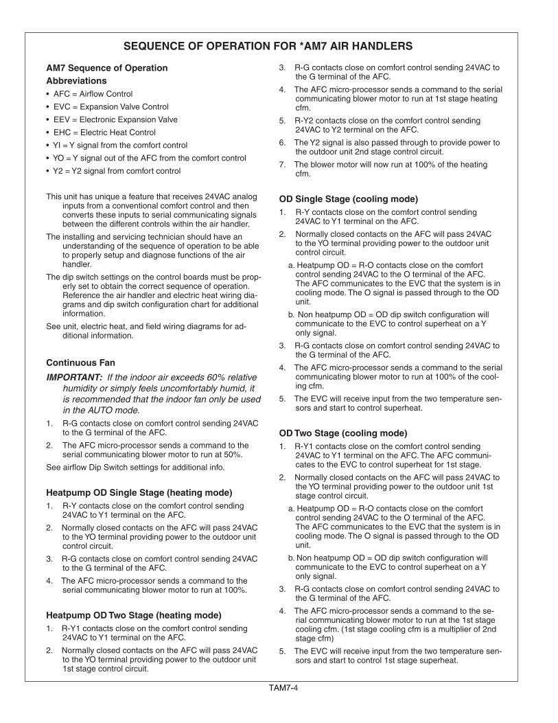
SEQUENCE OF OPERATION FOR *AM7 AIR HANDLERS
3. R-G contacts close on comfort control sending 24VAC to the G terminal of the AFC.
4. The AFC micro-processor sends a command to the serial communicating blower motor to run at 1st stage heating cfm.
5. R-Y2 contacts close on the comfort control sending 24VAC to Y2 terminal on the AFC.
6. The Y2 signal is also passed through to provide power to the outdoor unit 2nd stage control circuit.
7. The blower motor will now run at 100% of the heating cfm.
OD Single Stage (cooling mode)1. R-Y contacts close on the comfort control sending
24VAC to Y1 terminal on the AFC.
2. Normally closed contacts on the AFC will pass 24VAC to the YO terminal providing power to the outdoor unit control circuit.
a. Heatpump OD = R-O contacts close on the comfort control sending 24VAC to the O terminal of the AFC. The AFC communicates to the EVC that the system is in cooling mode. The O signal is passed through to the OD unit.
b. Non heatpump OD = OD dip switch configuration will communicate to the EVC to control superheat on a Y only signal.
3. R-G contacts close on comfort control sending 24VAC to the G terminal of the AFC.
4. The AFC micro-processor sends a command to the serial communicating blower motor to run at 100% of the cool-ing cfm.
5. The EVC will receive input from the two temperature sen-sors and start to control superheat.
OD Two Stage (cooling mode)1. R-Y1 contacts close on the comfort control sending
24VAC to Y1 terminal on the AFC. The AFC communi-cates to the EVC to control superheat for 1st stage.
2. Normally closed contacts on the AFC will pass 24VAC to the YO terminal providing power to the outdoor unit 1st stage control circuit.
a. Heatpump OD = R-O contacts close on the comfort control sending 24VAC to the O terminal of the AFC. The AFC communicates to the EVC that the system is in cooling mode. The O signal is passed through to the OD unit.
b. Non heatpump OD = OD dip switch configuration will communicate to the EVC to control superheat on a Y only signal.
3. R-G contacts close on comfort control sending 24VAC to the G terminal of the AFC.
4. The AFC micro-processor sends a command to the se-rial communicating blower motor to run at the 1st stage cooling cfm. (1st stage cooling cfm is a multiplier of 2nd stage cfm)
5. The EVC will receive input from the two temperature sen-sors and start to control 1st stage superheat.
AM7 Sequence of OperationAbbreviations•AFC=AirflowControl
•EVC=ExpansionValveControl
•EEV=ElectronicExpansionValve
•EHC=ElectricHeatControl
•YI=Ysignalfromthecomfortcontrol
•YO=YsignaloutoftheAFCfromthecomfortcontrol
•Y2=Y2signalfromcomfortcontrol
This unit has unique a feature that receives 24VAC analog inputs from a conventional comfort control and then converts these inputs to serial communicating signals between the different controls within the air handler.
The installing and servicing technician should have an understanding of the sequence of operation to be able to properly setup and diagnose functions of the air handler.
The dip switch settings on the control boards must be prop-erly set to obtain the correct sequence of operation. Reference the air handler and electric heat wiring dia-grams and dip switch configuration chart for additional information.
See unit, electric heat, and field wiring diagrams for ad-ditional information.
Continuous Fan
IMPORTANT: If the indoor air exceeds 60% relative humidity or simply feels uncomfortably humid, it is recommended that the indoor fan only be used in the AUTO mode.
1. R-G contacts close on comfort control sending 24VAC to the G terminal of the AFC.
2. The AFC micro-processor sends a command to the serial communicating blower motor to run at 50%.
SeeairflowDipSwitchsettingsforadditionalinfo.
Heatpump OD Single Stage (heating mode)1. R-Y contacts close on the comfort control sending
24VAC to Y1 terminal on the AFC.
2. Normally closed contacts on the AFC will pass 24VAC to the YO terminal providing power to the outdoor unit control circuit.
3. R-G contacts close on comfort control sending 24VAC to the G terminal of the AFC.
4. The AFC micro-processor sends a command to the serial communicating blower motor to run at 100%.
Heatpump OD Two Stage (heating mode)1. R-Y1 contacts close on the comfort control sending
24VAC to Y1 terminal on the AFC.
2. Normally closed contacts on the AFC will pass 24VAC to the YO terminal providing power to the outdoor unit 1st stage control circuit.
TAM75
6. R-Y2 contacts close on the comfort control sending 24VAC to Y2 terminal on the AFC. The AFC communi-cates to the EVC to control superheat for 2nd stage.
7. The Y2 signal is passed through to provide power to the outdoor unit 2nd stage control circuit.
8. The blower motor will now run at 100% of the cooling cfm.
Cooling OD 1 stage1. R-Y contacts close on the comfort control sending
24VAC to Y1 terminal on the AFC.
2. Normally closed contacts on the AFC will pass 24VAC to the YO terminal providing power to the outdoor unit control circuit.
3. R-G contacts close on comfort control sending 24VAC to the G terminal of the AFC.
4. The AFC micro-processor sends a command to the se-rial communicating blower motor to run at 100% of the cooling cfm.
5. The EVC will receive input from the two temperature sensors and start to control superheat.
Cooling OD Two stage 1. R-Y1 contacts close on the comfort control sending
24VAC to Y1 terminal on the AFC. The AFC communi-cates to the EVC to control superheat for 1st stage.
2. Normally closed contacts on the AFC will pass 24VAC to the YO terminal providing power to the outdoor unit 1st stage control circuit.
3. R-G contacts close on comfort control sending 24VAC to the G terminal of the AFC.
4. The AFC micro-processor sends a command to the se-rial communicating blower motor to run at the 1st stage cooling cfm. (1st stage cooling cfm is a multiplier of 2nd stage cfm)
5. The EVC will receive input from the two temperature sensors and start to control 1st stage superheat.
6. R-Y2 contacts close on the comfort control sending 24VAC to Y2 terminal on the AFC. The AFC communi-cates to the EVC to control superheat for 2nd stage.
7. The Y2 signal is passed through to provide power to the outdoor unit 2nd stage control circuit.
8. The blower motor will now run at 100% of the cooling cfm.
Electric Heat 1. R-W contacts close on the comfort control sending
24VAC to W1 of the AFC.
2. R-G contacts close on the comfort control sending 24VAC to G of the AFC.
3. The AFC communicates to the EHC that 1st stage elec-tric heat is being called upon.
4. The EHC determines the number of elements that are used for 1st stage and sends a message to the AFC for that correct cfm. (The EHC determines the amount of heat per stage by either factory programming or by the kw jumper position)
5. The AFC micro-processor sends a command to the serial communicating blower motor to run and close the blower interlock relay on the EHC. The blower motor will now run at the W1 electric heat cfm.
6. On subsequent calls for W2 and/or W3, the EHC will communicatetotheAFCtherequiredairflowrequestandenergize the additional relays.
NOTE: The EHC has “lead-lag” logic built in that energizes the electric heat relays based upon cycle counts.
For example: BAYEV**15 – The first time W1 only is ener-gized; the K1 relay would close and energize the “A” heater. The second time W1 only is energized; the K2 relay would close and energize the “B” heater. The third time W1 only is energized; the K3 relay would close and energize the “C” heater.
Defrost1. The OD unit will initiate defrost and send 24VAC to the O
terminal of the AFC.
2. The AFC will communicate to the EVC that the OD is in defrost and the EVC will start to maintain the correct superheat.
3. X2 from the OD will send 24VAC to W1 of the AFC.
4. The AFC communicates to the EHC that 1st stage elec-tric heat is being called upon.
5. The EHC determines the number of elements that are used for 1st stage and sends a message to the AFC for that correct cfm.
Optional Condensate Switch1. An optional OEM condensate switch can be installed
within the unit. This switch is only available through the National Distribution Center or Global Parts.
2. Switch contacts are normally open and close when water levelrises.Theclosedswitchwillinterruptcurrentflowtothe YO terminal and de-energize the OD unit.
3. Switch is only operational during cooling mode. Conden-sateoverflowisnotoperationalduringheatingordefrostmodes.
Standard aftermarket condensate switches cannot be used within the unit but can be installed exterior of the unit. Switch should be wired in series with YO wiring to the OD unit.
Freeze Protection1. The EVC control has the ability to sense when the coil is
beginning to ice. When this event occurs, the contacts to the YO circuit will open and de-energize the OD unit.
2. The indoor blower motor will continue to run to aid in defrosting the coil. After 20 minutes, the YO contacts will close and cooling operation will begin again.
Blower Delays1. Blower delays can be set to enhance system efficiency.
See S2 dip switch settings table.
TAM76
Pb
FAULT
UNIT
483332
1716 1
64
49
B K Jumper
TEST
TRANE U.S. INC.
VDD
PGD
MCLR
VSS
PGC
3.3V
SCLSDA
GND
HUMPART NO. LABEL
BAR CODE
12
34
5
STATUSYo Jumper
+13.8V
C60
C59
R57 R58
R64R65
R76R78
S3
R110
R41
R68C40
R93
R109
R12
R55
R23
R20
R49
R13
R14
D23
D19D18
C46
C39
C6
C23
R80
R71
R67
R52
R75R72
C41
R61
Q6
Q7
R1
R33
R34
J4
Q1
X1
U4
U3
TZ2
T2T1
R99
R98
R97
R60
R96
R95
R21
R91
R87
R88R70
R86
R83
R81
R66
R79
R77
R54
R103R106
R4
R104
R51
R5
R47
R42
R39
R82
R37
R35
R31
R74R89
R25 R18
R19
R10
R9
R8R3
R2
R5
R7
Q8
MOV1
L2
L3
K1
J3
J6
J9
D36
D35
D1
D22
D29
D25
D24
D7 D4
D2
D28
C57
C54
C51
C49C48
C47C52
C43
C42
C36
C35
C34
C31
C30C29
C7C3
C2
C1
U1
C58
R105
C50
U2
R24 R17
D6 D3
R NET
R NET 2
R73
1
J8
YoR
BOY1
J1
W2W1
R63R62R56
D21D20 C32C33
R38 R36
R16R15
R32
R11R28 R27R26
D13
D12
D5D11
D10
C24C25
C4C5C16C17 D8
R50R45
R85 R84
D16D15
D31D30
C26C27
C44C45
D32
D33
R94
R100
R101
R10
7
K2
R6
C53
C22
C19
C15
C12
C9
C8
C11
C14
C18
C21
D26
R69
C37
C38
L1
R102
D27
R40
R46R43
Q3Q
11
HP
OU
Airflow Control (AFC)
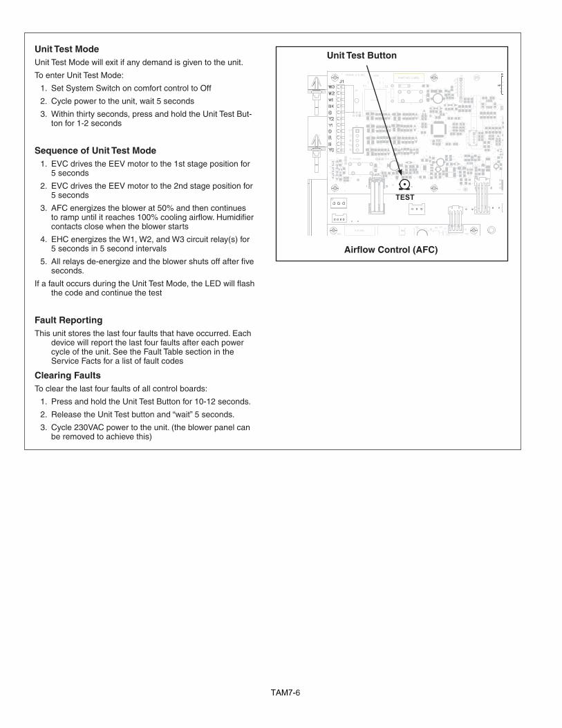
Unit Test ButtonUnit Test ModeUnit Test Mode will exit if any demand is given to the unit.
To enter Unit Test Mode:
1. Set System Switch on comfort control to Off
2. Cycle power to the unit, wait 5 seconds
3. Within thirty seconds, press and hold the Unit Test But-ton for 1-2 seconds
Sequence of Unit Test Mode 1. EVC drives the EEV motor to the 1st stage position for
5 seconds
2. EVC drives the EEV motor to the 2nd stage position for 5 seconds
3. AFC energizes the blower at 50% and then continues torampuntilitreaches100%coolingairflow.Humidifiercontacts close when the blower starts
4. EHC energizes the W1, W2, and W3 circuit relay(s) for 5 seconds in 5 second intervals
5. All relays de-energize and the blower shuts off after five seconds.
IfafaultoccursduringtheUnitTestMode,theLEDwillflashthe code and continue the test
Fault ReportingThis unit stores the last four faults that have occurred. Each
device will report the last four faults after each power cycle of the unit. See the Fault Table section in the Service Facts for a list of fault codes
Clearing FaultsTo clear the last four faults of all control boards:
1. Press and hold the Unit Test Button for 10-12 seconds.
2. Release the Unit Test button and “wait” 5 seconds.
3. Cycle 230VAC power to the unit. (the blower panel can be removed to achieve this)
TAM77
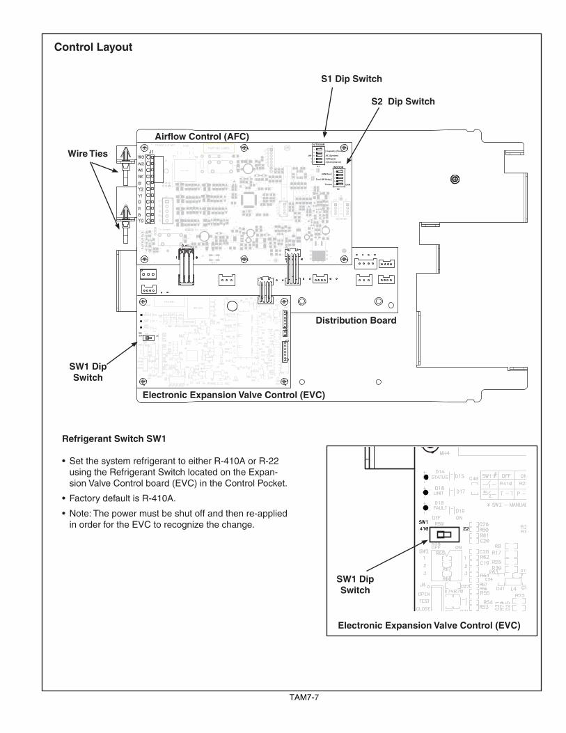
Refrigerant Switch SW1
• Set the system refrigerant to either R-410A or R-22 using the Refrigerant Switch located on the Expan-sion Valve Control board (EVC) in the Control Pocket.
• Factory default is R-410A.
• Note: The power must be shut off and then re-applied in order for the EVC to recognize the change.
Wire TiesPb
FAULT
UNIT
483332
1716 1
64
49
BK Jumper
TEST
TRANE U.S. INC.
VDD
PGD
MCLR
VSS
PGC
3.3V
SCLSDA
GND
HUM
5V
MOTOR
GND
RX
TX
+12V
PART NO. LABEL
BAR CODE
12
34
5
12
34
5STATUS
Yo Jumper
+12V
+13.8V
C60
C59
R57 R58
R64R65
R76R78
C20
C28
C55
S3
R110
R59
R41
R68C40
R108
R93
R109
R12
R55
R23
R20
R49
R13
R14
D23
D19D18
C46
C39
C6
C23
R80
J13
R71
R67
R52
R75R72
Q2
C41
R61
Q6
Q7
R1
R33
R34
J4
Q1
X1
U5
U4
U3
TZ2
T2T1
R99
R98
R97
R60
R96
R95
R21
R91
R87
R88R70
R86
R83
R81
R66
R79
R77
R54
R103R106
R4
R104
R51
R53
R48
R47
R44
R42
R39
R82
R37
R35
R31
R30
R74R89
R25 R18
R19
R10
R9
R8R3
R2
R5
R7
Q8
Q4
PTC
1
MOV1
L2
L3
K1
J3
J6
J9
D36
D35
D34
D1
D22
D29
D25
D24
D7 D4
D2
D28
C57
C54
C56
C51
C49C48
C47C52
C43
C42
C36
C35
C34
C31
C30C29
C13
C7C3
C2
C1
U1
C58
R105
C50
U2
J7
R24 R17
D6 D3
D14
D17
R NET 1
R NET 2
R73
1
J8
YoR
BOY1
J1
W2W1
R63R62R56
D21D20 C32C33
R38 R36
R16R15
R32
R11R28 R27R26
D13
D12
D5D11
D10
C24C25
C4C5C16C17 D8
R50R45
R85 R84
D16D15
D31D30
C26C27
C44C45
D32
D33
R94
R100
R101
R10
7
R29
K2
R6
C53
C22
C19
C15
C12
C9
C8
C11
C14
C18
C21
D26
R69
C37
C38
C10
D9
L1
R102
D27
R40
R22
R46R43
Q3Q5
11
HP
2 (Compressor)2 (Stages)AC (System)
} Capacity (Tons)
OUTDOOR
}
Torque
CFM/Ton
Cool Off Delay }
INDOOR
CFM
S1on
on
S2
S2 Dip Switch
S1 Dip Switch
SW1 Dip Switch
SW1 Dip Switch
Pb
FAULT
UNIT
483332
1716 1
64
49
BK Jumper
TEST
TRANE U.S. INC.
VDD
PGD
MCLR
VSS
PGC
3.3V
SCLSDA
GND
HUM
5V
MOTOR
GND
RX
TX
+12V
PART NO. LABEL
BAR CODE
12
34
5
12
34
5
STATUSYo Jumper
+12V
+13.8V
C60
C59
R57 R58
R64R65
R76R78
C20
C28
C55
S3
R110
R59
R41
R68C40
R108
R93
R109
R12
R55
R23
R20
R49
R13
R14
D23
D19D18
C46
C39
C6
C23
R80
J13
R71
R67
R52
R75R72
Q2
C41
R61
Q6
Q7
R1
R33
R34
J4
Q1
X1
U5
U4
U3
TZ2
T2T1
R99
R98
R97
R60
R96
R95
R21
R91
R87
R88R70
R86
R83
R81
R66
R79
R77
R54
R103R106
R4
R104
R51
R53
R48
R47
R44
R42
R39
R82
R37
R35
R31
R30
R74R89
R25 R18
R19
R10
R9
R8R3
R2
R5
R7
Q8
Q4
PTC
1
MOV1
L2
L3
K1
J3
J6
J9
D36
D35
D34
D1
D22
D29
D25
D24
D7 D4
D2
D28
C57
C54
C56
C51
C49C48
C47C52
C43
C42
C36
C35
C34
C31
C30C29
C13
C7C3
C2
C1
U1
C58
R105
C50
U2
J7
R24 R17
D6 D3
D14
D17
R NET 1
R NET 2
R73
1
J8
YoR
BOY1
J1
W2W1
R63R62R56
D21D20 C32C33
R38 R36
R16R15
R32
R11R28 R27R26
D13
D12
D5D11
D10
C24C25
C4C5C16C17 D8
R50R45
R85 R84
D16D15
D31D30
C26C27
C44C45
D32
D33
R94
R100
R101
R10
7
R29
K2
R6
C53
C22
C19
C15
C12
C9
C8
C11
C14
C18
C21
D26
R69
C37
C38
C10
D9
L1
R102
D27
R40
R22
R46R43
Q3Q5
11
HP
2 (Compressor)2 (Stages)AC (System)
} Capacity (Tons)
OUTDOOR
}
Torque
CFM/Ton
Cool Off Delay }
INDOOR
CFM
S1on
on
S2
Airflow Control (AFC)
Distribution Board
Electronic Expansion Valve Control (EVC)
Electronic Expansion Valve Control (EVC)
Control Layout
TAM78
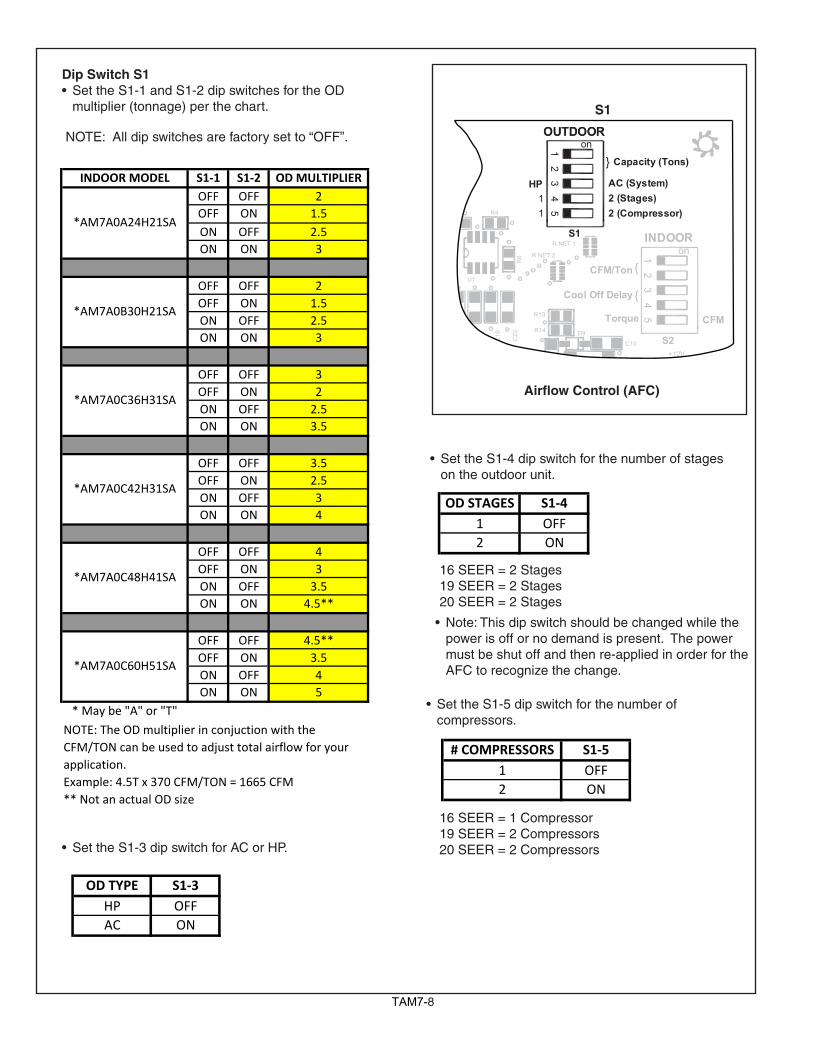
Dip Switch S1 • Set the S1-1 and S1-2 dip switches for the OD multiplier (tonnage) per the chart.
NOTE: All dip switches are factory set to “OFF”.
INDOOR MODEL S1‐1 S1‐2 OD MULTIPLIEROFF OFF 2OFF ON 1.5ON OFF 2.5ON ON 3
OFF OFF 2OFF ON 1.5ON OFF 2.5ON ON 3
OFF OFF 3OFF ON 2ON OFF 2.5ON ON 3.5
OFF OFF 3.5OFF ON 2.5ON OFF 3ON ON 4
OFF OFF 4OFF ON 3ON OFF 3.5ON ON 4.5**
OFF OFF 4.5**OFF ON 3.5ON OFF 4ON ON 5
* May be "A" or "T"
** Not an actual OD size
NOTE: The OD multiplier in conjuction with the CFM/TON can be used to adjust total airflow for your application. Example: 4.5T x 370 CFM/TON = 1665 CFM
*AM7A0C42H31SA
*AM7A0C48H41SA
*AM7A0C60H51SA
*AM7A0A24H21SA
*AM7A0B30H21SA
*AM7A0C36H31SA
• Set the S1-3 dip switch for AC or HP.
OD TYPE S1‐3HP OFFAC ON
S1
Airflow Control (AFC)
11
12
34
5
12
34
5
HP
2 (Compressor)2 (Stages)AC (System)
}
OUTDOOR
Capacity (Tons)
OUTDOOR
}
Torque
CFM/Ton
Cool Off Delay }
INDOOR
CFM
+12V
R13
R14
R1
R4
1
U1
R NET 1S1
on
on
S2
R NET 2
R6
C22
C19
C15
C12
C18
C21
C10
D9
L1
R22
• Set the S1-4 dip switch for the number of stages on the outdoor unit.
OD STAGES S1‐41 OFF2 ON
• Set the S1-5 dip switch for the number of compressors.
# COMPRESSORS S1‐51 OFF2 ON
16 SEER = 1 Compressor19 SEER = 2 Compressors20 SEER = 2 Compressors
16 SEER = 2 Stages19 SEER = 2 Stages20 SEER = 2 Stages
• Note: This dip switch should be changed while the power is off or no demand is present. The power must be shut off and then re-applied in order for the AFC to recognize the change.
TAM79
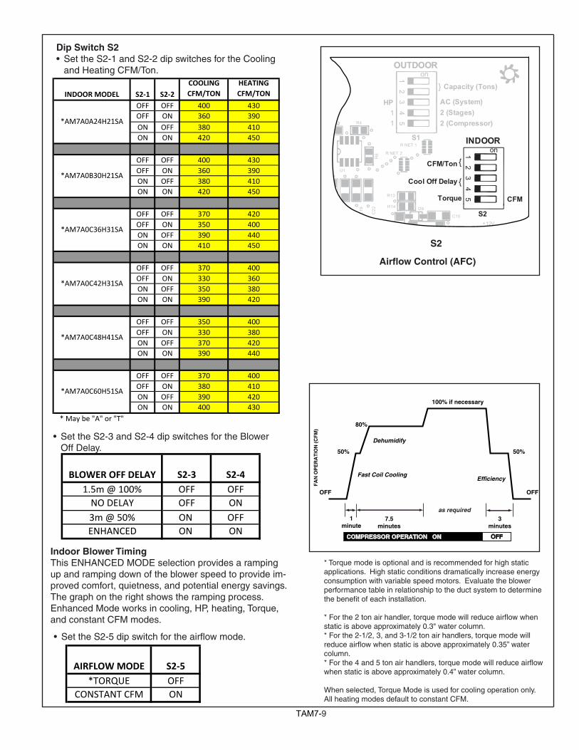
Dip Switch S2 • Set the S2-1 and S2-2 dip switches for the Cooling and Heating CFM/Ton.
• Set the S2-3 and S2-4 dip switches for the Blower Off Delay.
BLOWER OFF DELAY S2‐3 S2‐41.5m @ 100% OFF OFFNO DELAY OFF ON3m @ 50% ON OFFENHANCED ON ON
AIRFLOW MODE S2‐5*TORQUE OFF
CONSTANT CFM ON
• Set the S2-5 dip switch for the airflow mode.
Indoor Blower TimingThis ENHANCED MODE selection provides a ramping up and ramping down of the blower speed to provide im-proved comfort, quietness, and potential energy savings. The graph on the right shows the ramping process.Enhanced Mode works in cooling, HP, heating, Torque, and constant CFM modes.
OFF OFF
50%
80%
100% if necessary
50%
Dehumidify
Fast Coil CoolingEfficiency
7.5minutes
3minutes
1minute
FA
N O
PE
RA
TIO
N (
CF
M)
COMPRESSOR OPERATION ON OFF
as required
S2
11
12
34
5
12
34
5HP
2 (Compressor)2 (Stages)AC (System)
}
OUTDOOR
Capacity (Tons)
OUTDOOR
}
Torque
CFM/Ton
Cool Off Delay }
INDOOR
CFM
+12V
R13
R14
R1
R4
1
U1
R NET 1S1
on
on
S2
R NET 2
R6
C22
C19
C15
C12
C18
C21
C10
D9
L1
R22
Airflow Control (AFC)
* Torque mode is optional and is recommended for high static applications. High static conditions dramatically increase energy consumption with variable speed motors. Evaluate the blower performance table in relationship to the duct system to determine the benefit of each installation.
*Forthe2tonairhandler,torquemodewillreduceairflowwhenstatic is above approximately 0.3" water column.* For the 2-1/2, 3, and 3-1/2 ton air handlers, torque mode will reduceairflowwhenstaticisaboveapproximately0.35”watercolumn.*Forthe4and5tonairhandlers,torquemodewillreduceairflowwhen static is above approximately 0.4” water column.
When selected, Torque Mode is used for cooling operation only. All heating modes default to constant CFM.
INDOOR MODEL S2‐1 S2‐2COOLING CFM/TON
HEATING CFM/TON
OFF OFF 400 430OFF ON 360 390ON OFF 380 410ON ON 420 450
OFF OFF 400 430OFF ON 360 390ON OFF 380 410ON ON 420 450
OFF OFF 370 420OFF ON 350 400ON OFF 390 440ON ON 410 450
OFF OFF 370 400OFF ON 330 360ON OFF 350 380ON ON 390 420
OFF OFF 350 400OFF ON 330 380ON OFF 370 420ON ON 390 440
OFF OFF 370 400OFF ON 380 410ON OFF 390 420ON ON 400 430
* May be "A" or "T"
*AM7A0C60H51SA
*AM7A0A24H21SA
*AM7A0B30H21SA
*AM7A0C36H31SA
*AM7A0C42H31SA
*AM7A0C48H41SA
TAM710
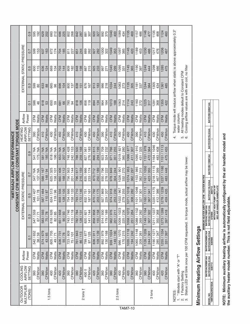
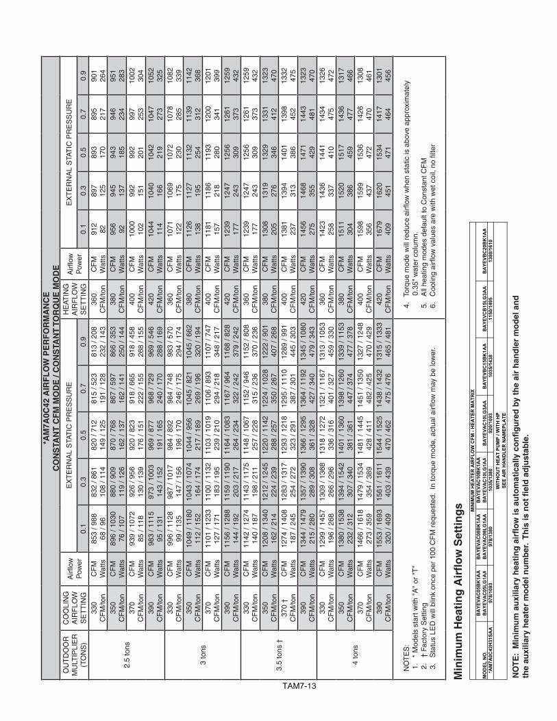
*AM
7A0A
24 A
IRF
LO
W P
ER
FO
RM
AN
CE
CO
NS
TAN
T C
FM
MO
DE
/ C
ON
STA
NT
TO
RQ
UE
MO
DE
OU
TD
OO
RM
ULT
IPLI
ER
(TO
NS
)
CO
OLI
NG
A
IRF
LOW
SE
TT
ING
Airfl
owP
ower
EX
TE
RN
AL
STA
TIC
PR
ES
SU
RE
HE
ATIN
G
AIR
FLO
WS
ET
TIN
G
Airfl
owP
ower
EX
TE
RN
AL
STA
TIC
PR
ES
SU
RE
0.1
0.3
0.5
0.7
0.9
0.1
0.3
0.5
0.7
0.9
1.5
tons
360
CF
M/to
nC
FM
Wat
ts54
2 / 6
5238
/ 59
547
/ 559
67 /
7154
8 / 4
0710
1 / 7
854
7 / N
A13
7 / N
A54
1 / N
A17
5 / N
A39
0 C
FM
/ton
CF
MW
atts
586
4659
980
600
115
599
153
595
192
380
CF
M/to
nC
FM
Wat
ts57
4 / 6
7943
/ 65
583
/ 593
75 /
7858
7 / 4
6411
0 / 8
758
8 / 1
6714
8 / 9
458
1 / N
A18
5 / N
A41
0 C
FM
/ton
CF
MW
atts
618
5363
388
636
124
637
163
629
202
400
CF
M/to
nC
FM
Wat
ts60
5 / 7
0549
/ 71
618
/ 626
82 /
8562
4 / 5
1311
9 / 9
662
5 / 3
2515
8 / 1
0161
8 / N
A19
6 / N
A43
0 C
FM
/ton
CF
MW
atts
650
5966
596
669
134
672
174
660
212
420
CF
M/to
nC
FM
Wat
ts63
6 / 7
3155
/ 78
651
/ 658
90 /
9365
9 / 5
5612
8 / 1
0566
0 / 4
0616
8 / 1
1265
3 / N
A20
7 / N
A45
0 C
FM
/ton
CF
MW
atts
681
6669
610
470
314
470
418
569
622
5
2 to
ns †
360
CF
M/to
nC
FM
Wat
ts72
3 / 8
0975
/ 10
174
3 / 7
4611
5 / 1
1875
4 / 6
6615
8 / 1
3375
6 / 5
6320
1 / 1
4474
8 / 4
2824
2 / 1
5339
0 C
FM
/ton
CF
MW
atts
780
9480
013
780
918
281
122
780
226
838
0 C
FM
/ton
CF
MW
atts
761
/ 843
86 /
113
782
/ 784
128
/ 131
793
/ 710
172
/ 146
796
/ 617
216
/ 159
788
/ 500
259
/ 168
410
CF
M/to
nC
FM
Wat
ts81
810
683
815
184
819
885
124
484
228
740
0 †
CF
M/to
nC
FM
Wat
ts79
9 / 8
7797
/ 12
582
0 / 8
2114
1 / 1
4483
2 / 7
5118
7 / 1
6183
5 / 6
6623
3 / 1
7482
7 / 5
6127
6 / 1
8343
0 C
FM
/ton
CF
MW
atts
856
119
876
167
887
215
889
262
881
307
420
CF
M/to
nC
FM
Wat
ts83
6 / 9
1110
9 / 1
3985
8 / 8
5815
5 / 1
5887
0 / 7
9220
3 / 1
7587
3 /7
1225
0 / 1
8986
6 / 6
1529
4 / 1
9945
0 C
FM
/ton
CF
MW
atts
894
134
913
183
925
233
927
282
920
327
2.5
tons
360
CF
M/to
nC
FM
Wat
ts89
2 / 9
7913
0 / 1
6891
4 / 9
3017
9 / 1
8992
7 / 8
6922
9 / 2
0793
0 / 7
9627
8 / 2
2292
3 / 7
0932
4 / 2
3239
0 C
FM
/ton
CF
MW
atts
964
164
986
218
997
271
1000
322
992
370
380
CF
M/to
nC
FM
Wat
ts93
9 / 1
024
149
/ 190
962
/ 976
201
/ 211
974
/ 918
253
/ 230
978
/ 849
304
/ 244
971
/ 766
351
/ 255
410
CF
M/to
nC
FM
Wat
ts10
1318
810
3424
410
4529
910
4935
310
4040
040
0 C
FM
/ton
CF
MW
atts
986
/ 107
017
0 / 2
1510
09 /
1023
225
/ 236
1022
/ 96
727
9 / 2
5510
26 /
901
332
/ 270
1019
/ 82
138
0 / 2
8043
0 C
FM
/ton
CF
MW
atts
1063
214
1083
273
1095
331
1097
385
1089
434
420
CF
M/to
nC
FM
Wat
ts10
35 /
1118
194
/ 242
1058
/ 10
7225
1 / 2
6410
71 /
1018
308
/ 282
1074
/ 95
336
2 / 2
9710
66 /
877
411
/ 307
450
CF
M/to
nC
FM
Wat
ts11
1424
311
3530
511
4536
511
4542
011
3546
9
3 to
ns
360
CF
M/to
nC
FM
Wat
ts10
65 /
1148
209
/ 261
1088
/ 11
0226
9 / 2
8211
01 /
1048
327
/ 301
1103
/ 98
538
2 / 3
1510
95 /
910
431
/ 325
390
CF
M/to
nC
FM
Wat
ts11
6027
211
8133
711
9039
711
8945
311
5748
638
0 C
FM
/ton
CF
MW
atts
1126
/ 12
0924
4 / 3
0111
49 /
1164
307
/ 322
1160
/ 11
1136
7 / 3
4111
61 /
1050
423
/ 355
1151
/ 97
847
2 / 3
6441
0 C
FM
/ton
CF
MW
atts
1225
317
1244
384
1249
444
1230
486
1146
477
400
CF
M/to
nC
FM
Wat
ts11
90 /
1271
285
/ 347
1211
/ 12
2735
0 / 3
6812
20 /
1175
412
/ 386
1218
/ 11
1546
7 / 3
9911
64 /
1046
483
/ 408
430
CF
M/to
nC
FM
Wat
ts12
9136
813
0543
412
9848
612
1747
611
3546
842
0 C
FM
/ton
CF
MW
atts
1255
/ 13
3433
1 / 3
9712
73 /
1289
397
/ 418
1278
/ 12
3945
9 / 4
3512
37 /
1180
483
/ 448
1151
/ 11
1347
5 / 4
5545
0 C
FM
/ton
CF
MW
atts
1355
422
1361
485
1285
475
1206
467
1124
460
NO
TE
S:
1.
* M
odel
s st
art w
ith "
A"
or "
T"
2.
† F
acto
ry S
ettin
g3
.S
tatu
sLE
Dw
illb
link
once
per
100
CF
Mr
eque
sted
.In
torq
uem
ode,
act
uala
irflow
may
be
low
er.
4.
Tor
que
mod
ew
illr
educ
eai
rflow
whe
nst
atic
isa
bove
app
roxi
mat
ely
0.3"
w
ater
col
umn.
5.
All
heat
ing
mod
es d
efau
lt to
Con
stan
t CF
M6
.C
oolin
gai
rflow
val
ues
are
with
wet
coi
l,no
filte
r
NO
TE
: M
inim
um
au
xilia
ry h
eati
ng
air
flo
w is
au
tom
atic
ally
co
nfi
gu
red
by
the
air
han
dle
r m
od
el a
nd
th
e au
xilia
ry h
eate
r m
od
el n
um
ber
. T
his
is n
ot
fiel
d a
dju
stab
le.
Min
imu
m H
eati
ng
Air
flo
w S
etti
ng
s
MO
DEL
NO
.B
AYE
VAC
05B
K1A
AB
AYE
VAC
05LG
1AA
BA
YEVA
C08
BK
1AA
BA
YEVA
C08
LG1A
AB
AYE
VAC
10B
K1A
AB
AYE
VAC
10LG
1AA
BA
YEVA
C10
LG3A
AB
AYE
VBC
15B
K1A
AB
AYE
VCB
15LG
3AA
BA
YEVB
C20
BK
1AA
*AM
7A0A
24H
21SA
A63
8/71
363
8/90
067
5/90
060
0/71
3--
----
MIN
IMU
M H
EATE
R A
IRFL
OW
CFM
- H
EATE
R M
ATR
I X
WIT
HO
UT
HEA
T PU
MP
/ WIT
H H
PSE
E A
IR H
AN
DLE
R N
AM
EPLA
TE
TAM711
MO
DEL
NO
.B
AYE
VAC
05B
K1A
AB
AYE
VAC
05LG
1AA
BA
YEVA
C08
BK
1AA
BA
YEVA
C08
LG1A
AB
AYE
VAC
10B
K1A
AB
AYE
VAC
10LG
1AA
BA
YEVA
C10
LG3A
AB
AYE
VBC
15B
K1A
AB
AYE
VCB
15LG
3AA
BA
YEVB
C20
BK
1AA
*AM
7A0B
30H
21SA
A72
3/80
872
3/10
2076
5/10
2068
0/80
876
5/10
6385
0/11
05--
MIN
IMU
M H
EATE
R A
IRFL
OW
CFM
- H
EATE
R M
ATR
IX
WIT
HO
UT
HEA
T PU
MP
/ WIT
H H
PSE
E A
IR H
AN
DLE
R N
AM
EPLA
TE
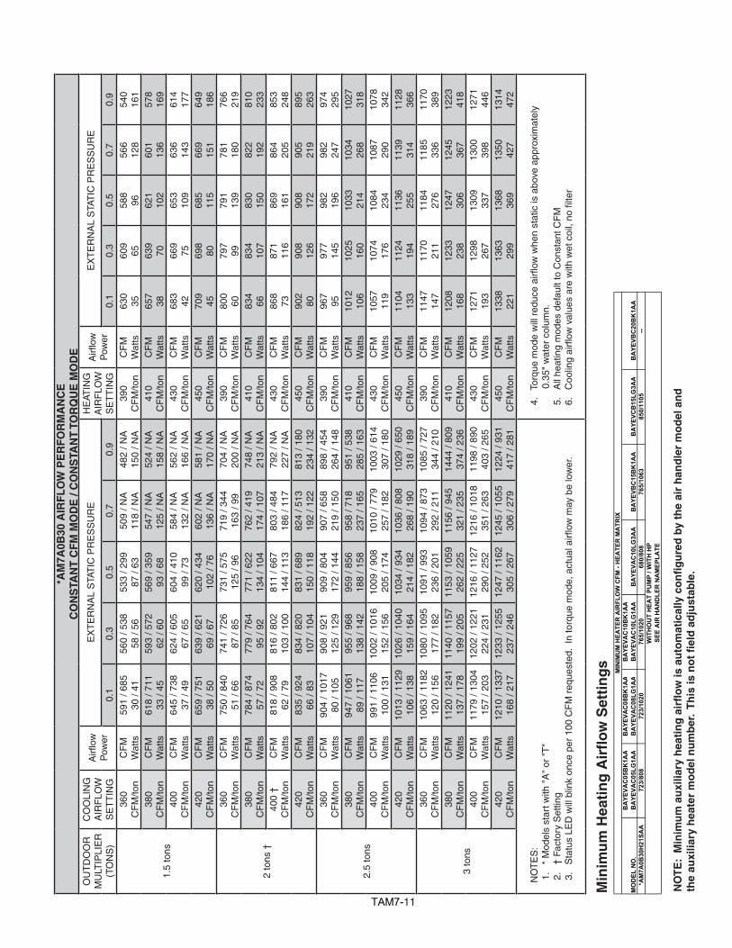
*AM
7A0B
30 A
IRF
LO
W P
ER
FO
RM
AN
CE
CO
NS
TAN
T C
FM
MO
DE
/ C
ON
STA
NT
TO
RQ
UE
MO
DE
OU
TD
OO
RM
ULT
IPLI
ER
(TO
NS
)
CO
OLI
NG
A
IRF
LOW
SE
TT
ING
Airfl
owP
ower
EX
TE
RN
AL
STA
TIC
PR
ES
SU
RE
HE
ATIN
G
AIR
FLO
WS
ET
TIN
G
Airfl
owP
ower
EX
TE
RN
AL
STA
TIC
PR
ES
SU
RE
0.1
0.3
0.5
0.7
0.9
0.1
0.3
0.5
0.7
0.9
1.5
tons
360
CF
M/to
nC
FM
Wat
ts59
1 / 6
8530
/ 41
560
/ 538
58 /
5653
3 / 2
9987
/ 63
509
/ NA
118
/ NA
482
/ NA
150
/ NA
390
CF
M/to
nC
FM
Wat
ts63
035
609
6558
896
566
128
540
161
380
CF
M/to
nC
FM
Wat
ts61
8 / 7
1133
/ 45
593
/ 572
62 /
6056
9 / 3
5993
/ 68
547
/ NA
125
/ NA
524
/ NA
158
/ NA
410
CF
M/to
nC
FM
Wat
ts65
738
639
7062
110
260
113
657
816
940
0 C
FM
/ton
CF
MW
atts
645
/ 738
37 /
4962
4 / 6
0567
/ 65
604
/ 410
99 /
7358
4 / N
A13
2 / N
A56
2 / N
A16
6 / N
A43
0 C
FM
/ton
CF
MW
atts
683
4266
975
653
109
636
143
614
177
420
CF
M/to
nC
FM
Wat
ts65
9 / 7
5138
/ 50
639
/ 621
69 /
6762
0 / 4
3410
2 / 7
660
2 / N
A13
6 / N
A58
1 / N
A17
0 / N
A45
0 C
FM
/ton
CF
MW
atts
709
4569
880
685
115
669
151
649
186
2 to
ns †
360
CF
M/to
nC
FM
Wat
ts75
0 / 8
4051
/ 66
741
/ 726
87 /
8573
1 / 5
7512
5 / 9
671
9 / 3
4416
3 / 9
970
4 / N
A20
0 / N
A39
0 C
FM
/ton
CF
MW
atts
800
6079
799
791
139
781
180
766
219
380
CF
M/to
nC
FM
Wat
ts78
4 / 8
7457
/ 72
779
/ 764
95 /
9277
1 / 6
2213
4 / 1
0476
2 / 4
1917
4 / 1
0774
8 / N
A21
3 / N
A41
0 C
FM
/ton
CF
MW
atts
834
6683
410
783
015
082
219
281
023
340
0 †
CF
M/to
nC
FM
Wat
ts81
8 / 9
0862
/ 79
816
/ 802
103
/ 100
811
/ 667
144
/ 113
803
/ 484
186
/ 117
792
/ NA
227
/ NA
430
CF
M/to
nC
FM
Wat
ts86
873
871
116
869
161
864
205
853
248
420
CF
M/to
nC
FM
Wat
ts83
5 / 9
2466
/ 83
834
/ 820
107
/ 104
831
/ 689
150
/ 118
824
/ 513
192
/ 122
813
/ 180
234
/ 132
450
CF
M/to
nC
FM
Wat
ts90
280
908
126
908
172
905
219
895
263
2.5
tons
360
CF
M/to
nC
FM
Wat
ts90
4 / 1
017
80 /
105
908
/ 921
125
/ 129
909
/ 804
172
/ 144
907
/ 658
219
/ 150
898
/ 454
264
/ 148
390
CF
M/to
nC
FM
Wat
ts96
795
977
145
982
196
982
247
974
295
380
CF
M/to
nC
FM
Wat
ts94
7 / 1
061
89 /
117
955
/ 968
138
/ 142
959
/ 856
188
/ 158
958
/ 718
237
/ 165
951
/ 538
285
/ 163
410
CF
M/to
nC
FM
Wat
ts10
1210
610
2516
010
3321
410
3426
810
2731
840
0 C
FM
/ton
CF
MW
atts
991
/ 110
610
0 / 1
3110
02 /
1016
152
/ 156
1009
/ 90
820
5 / 1
7410
10 /
779
257
/ 182
1003
/ 61
430
7 / 1
8043
0 C
FM
/ton
CF
MW
atts
1057
119
1074
176
1084
234
1087
290
1078
342
420
CF
M/to
nC
FM
Wat
ts10
13 /
1129
106
/ 138
1026
/ 10
4015
9 / 1
6410
34 /
934
214
/ 182
1036
/ 80
826
8 / 1
9010
29 /
650
318
/ 189
450
CF
M/to
nC
FM
Wat
ts11
0413
311
2419
411
3625
511
3931
411
2836
6
3 to
ns
360
CF
M/to
nC
FM
Wat
ts10
63 /
1182
120
/ 156
1080
/ 10
9517
7 / 1
8210
91 /
993
236
/ 201
1094
/ 87
329
2 / 2
1110
85 /
727
344
/ 210
390
CF
M/to
nC
FM
Wat
ts11
4714
711
7021
111
8427
611
8533
611
7038
938
0 C
FM
/ton
CF
MW
atts
1120
/ 12
4113
7 / 1
7811
40 /
1157
199
/ 205
1153
/ 10
5926
2 / 2
2511
56 /
945
321
/ 235
1444
/ 80
937
4 / 2
3641
0 C
FM
/ton
CF
MW
atts
1208
168
1233
238
1247
306
1245
367
1223
418
400
CF
M/to
nC
FM
Wat
ts11
79 /
1304
157
/ 203
1202
/ 12
2122
4 / 2
3112
16 /
1127
290
/ 252
1216
/ 10
1835
1 / 2
6311
98 /
890
403
/ 265
430
CF
M/to
nC
FM
Wat
ts12
7119
312
9826
713
0933
713
0039
812
7144
642
0 C
FM
/ton
CF
MW
atts
1210
/ 13
3716
8 / 2
1712
33 /
1255
237
/ 246
1247
/ 11
6230
5 / 2
6712
45 /
1055
306
/ 279
1224
/ 93
141
7 / 2
8145
0 C
FM
/ton
CF
MW
atts
1338
221
1363
299
1368
369
1350
427
1314
472
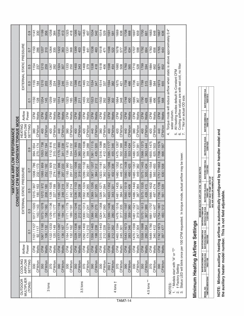
NO
TE
S:
1.
* M
odel
s st
art w
ith "
A"
or "
T"
2.
† F
acto
ry S
ettin
g3
.S
tatu
sLE
Dw
illb
link
once
per
100
CF
Mr
eque
sted
.In
torq
uem
ode,
act
uala
irflow
may
be
low
er.
4.
Tor
que
mod
ew
illr
educ
eai
rflow
whe
nst
atic
isa
bove
app
roxi
mat
ely
0.35
" w
ater
col
umn.
5.
All
heat
ing
mod
es d
efau
lt to
Con
stan
t CF
M6
.C
oolin
gai
rflow
val
ues
are
with
wet
coi
l,no
filte
r
Min
imu
m H
eati
ng
Air
flo
w S
etti
ng
s
NO
TE
: M
inim
um
au
xilia
ry h
eati
ng
air
flo
w is
au
tom
atic
ally
co
nfi
gu
red
by
the
air
han
dle
r m
od
el a
nd
th
e au
xilia
ry h
eate
r m
od
el n
um
ber
. T
his
is n
ot
fiel
d a
dju
stab
le.
TAM712
MO
DEL
NO
.B
AYE
VAC
05B
K1A
AB
AYE
VAC
05LG
1AA
BA
YEVA
C08
BK
1AA
BA
YEVA
C08
LG1A
AB
AYE
VAC
10B
K1A
AB
AYE
VAC
10LG
1AA
BA
YEVA
C10
LG3A
AB
AYE
VBC
15B
K1A
AB
AYE
VCB
15LG
3AA
BA
YEVB
C20
BK
1AA
*AM
7A0C
36H
31SA
A87
6/97
987
6/12
3692
7/12
3682
4/97
992
7/12
8810
30/1
339
1236
/144
2
MIN
IMU
M H
EATE
R A
IRFL
OW
CFM
- H
EATE
R M
ATR
I X
WIT
HO
UT
HEA
T PU
MP
/ WIT
H H
PSE
E A
IR H
AN
DLE
R N
AM
EPLA
TE
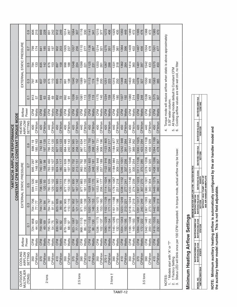
*AM
7A0C
36 A
IRF
LO
W P
ER
FO
RM
AN
CE
CO
NS
TAN
T C
FM
MO
DE
/ C
ON
STA
NT
TO
RQ
UE
MO
DE
OU
TD
OO
RM
ULT
IPLI
ER
(TO
NS
)
CO
OLI
NG
A
IRF
LOW
SE
TT
ING
Airfl
owP
ower
EX
TE
RN
AL
STA
TIC
PR
ES
SU
RE
HE
ATIN
G
AIR
FLO
WS
ET
TIN
G
Airfl
owP
ower
EX
TE
RN
AL
STA
TIC
PR
ES
SU
RE
0.1
0.3
0.5
0.7
0.9
0.1
0.3
0.5
0.7
0.9
2 to
ns
350
CF
M/to
nC
FM
Wat
ts72
4 / 8
5844
/ 63
704
/ 706
77 /
7769
4 / 5
3011
1 / 8
569
5 / 2
9714
8 / 9
069
8 / 1
918
5 / 1
6340
0 C
FM
/ton
CF
MW
atts
813
5779
794
794
133
799
174
806
215
370
CF
M/to
nC
FM
Wat
ts75
9 / 8
9249
/ 69
744
/ 747
84 /
8473
8 / 5
8512
0 / 9
374
0 / 3
8715
8 / 9
874
2 / 8
419
7 / 1
3542
0 C
FM
/ton
CF
MW
atts
849
6383
710
283
514
284
118
584
922
839
0 C
FM
/ton
CF
MW
atts
795
/ 924
54 /
7578
4 / 7
8791
/ 91
780
/ 635
129
/ 102
783
/ 460
169
/ 107
786
/ 213
209
/ 120
440
CF
M/to
nC
FM
Wat
ts88
469
876
110
876
153
883
197
891
242
410
CF
M/to
nC
FM
Wat
ts83
0 / 9
5760
/ 82
823
/ 826
99 /
9982
2 / 6
8313
9 / 1
1182
4 / 5
2418
0 / 1
1782
7 / 3
2922
2 / 1
2345
0 C
FM
/ton
CF
MW
atts
902
7289
511
489
715
890
220
391
224
9
2.5
tons
350
CF
M/to
nC
FM
Wat
ts87
9 / 1
026
68 /
9787
6 / 9
0511
0 / 1
1687
7 / 7
7615
3 / 1
3088
1 / 6
3919
7 / 1
3888
4 / 4
8824
0 / 1
4340
0 C
FM
/ton
CF
MW
atts
992
9199
113
899
818
810
0523
710
1428
737
0 C
FM
/ton
CF
MW
atts
923
/ 106
777
/ 10
792
4 / 9
5212
1 / 1
2792
7 / 8
3016
7 / 1
4293
2 / 7
0221
3 / 1
5193
6 / 5
6525
8 / 1
5742
0 C
FM
/ton
CF
MW
atts
1036
101
1040
152
1048
204
1057
256
1064
307
390
CF
M/to
nC
FM
Wat
ts96
8 / 1
110
86 /
118
971
/ 999
133
/ 139
977
/ 883
181
/ 155
983
/ 762
230
/ 166
987
/ 634
277
/ 172
440
CF
M/to
nC
FM
Wat
ts10
8111
310
8916
710
9922
111
1027
711
1633
041
0 C
FM
/ton
CF
MW
atts
1012
/ 11
5396
/ 13
010
20 /
1047
146
/ 153
1028
/ 93
519
7 / 1
7010
34 /
820
248
/ 181
1039
/ 70
029
8 / 1
8745
0 C
FM
/ton
CF
MW
atts
1105
119
1113
174
1125
231
1136
287
1141
341
3 to
ns †
350
CF
M/to
nC
FM
Wat
ts10
36 /
1175
102
/ 137
1044
/ 10
7015
3 / 1
6010
53 /
961
206
/ 177
1060
/ 84
825
7 / 1
8910
64 /
731
308
/ 196
400
CF
M/to
nC
FM
Wat
ts11
7514
011
8920
012
0326
112
1432
112
1537
737
0 †
CF
M/to
nC
FM
Wat
ts10
90 /
1229
116
/ 154
1102
/ 11
2917
1 / 1
7811
14 /
1024
227
/ 196
1122
/ 91
628
2 / 2
0911
23 /
805
334
/ 217
420
CF
M/to
nC
FM
Wat
ts12
3415
912
5122
312
6728
812
7535
112
7240
639
0C
FM
/ton
CF
MW
atts
1145
/ 12
8513
2 / 1
7311
61 /
1188
191
/ 198
1176
/ 10
8725
1 / 2
1811
84 /
984
309
/ 231
1184
/ 87
736
3 / 2
4044
0 C
FM
/ton
CF
MW
atts
1295
180
1315
250
1331
318
1335
381
1325
435
410
CF
M/to
nC
FM
Wat
ts12
04 /
1343
150
/ 195
1223
/ 12
4921
3 / 2
2112
38 /
1152
277
/ 241
1246
/ 10
5133
7 / 2
5612
42 /
948
391
/ 264
450
CF
M/to
nC
FM
Wat
ts13
2719
213
4826
413
6226
413
6439
613
5044
9
3.5
tons
350
CF
M/to
nC
FM
Wat
ts11
99 /
1338
149
/ 193
1218
/ 12
4421
1 / 2
1912
33 /
1146
274
/ 239
1241
/ 10
4633
5 / 2
5412
37 /
942
389
/ 262
400
CF
M/to
nC
FM
Wat
ts13
8021
414
0328
914
1436
014
0942
213
8947
237
0 C
FM
/ton
CF
MW
atts
1269
/ 14
0817
2 / 2
2212
91 /
1317
240
/ 249
1307
/ 12
2330
7 / 2
7013
11 /
1126
370
/ 285
1300
/ 10
2542
3 / 2
9442
0 C
FM
/ton
CF
MW
atts
1459
248
1478
327
1481
397
1467
456
1395
476
390
CF
M/to
nC
FM
Wat
ts13
42 /
1481
200
/ 255
1367
/ 13
9327
3 / 2
8213
80 /
1301
343
/ 304
1378
/ 12
0640
5 / 3
2013
58 /
1108
456
/ 329
440
CF
M/to
nC
FM
Wat
ts15
3828
715
5036
615
4243
315
0447
813
8847
241
0 C
FM
/ton
CF
MW
atts
1419
/ 15
5523
2 / 2
9114
42 /
1468
309
/ 319
1449
/ 13
7938
0 / 3
4114
38 /
1286
440
/ 357
1394
/ 11
8947
8 / 3
6745
0 C
FM
/ton
CF
MW
atts
1575
307
1583
385
1570
450
1501
477
1385
470
NO
TE
S:
1.
* M
odel
s st
art w
ith "
A"
or "
T"
2.
† F
acto
ry S
ettin
g3
.S
tatu
sLE
Dw
illb
link
once
per
100
CF
Mr
eque
sted
.In
torq
uem
ode,
act
uala
irflow
may
be
low
er.
4.
Tor
que
mod
ew
illr
educ
eai
rflow
whe
nst
atic
isa
bove
app
roxi
mat
ely
0.35
" w
ater
col
umn.
5.
All
heat
ing
mod
es d
efau
lt to
Con
stan
t CF
M6
.C
oolin
gai
rflow
val
ues
are
with
wet
coi
l,no
filte
r
Min
imu
m H
eati
ng
Air
flo
w S
etti
ng
s
NO
TE
: M
inim
um
au
xilia
ry h
eati
ng
air
flo
w is
au
tom
atic
ally
co
nfi
gu
red
by
the
air
han
dle
r m
od
el a
nd
th
e au
xilia
ry h
eate
r m
od
el n
um
ber
. T
his
is n
ot
fiel
d a
dju
stab
le.
TAM713
MO
DEL
NO
.B
AYE
VAC
05B
K1A
AB
AYE
VAC
05LG
1AA
BA
YEVA
C08
BK
1AA
BA
YEVA
C08
LG1A
AB
AYE
VAC
10B
K1A
AB
AYE
VAC
10LG
1AA
BA
YEVA
C10
LG3A
AB
AYE
VBC
15B
K1A
AB
AYE
VCB
15LG
3AA
BA
YEVB
C20
BK
1AA
*AM
7A0C
42H
31SA
A97
8/10
9397
8/13
8010
35/1
380
920/
1093
1035
/143
811
50/1
495
1380
/161
0
MIN
IMU
M H
EATE
R A
IRFL
OW
CFM
- H
EATE
R M
ATR
IX
WIT
HO
UT
HEA
T PU
MP
/ WIT
H H
PSE
E A
IR H
AN
DLE
R N
AM
EPLA
TE
Min
imu
m H
eati
ng
Air
flo
w S
etti
ng
s
*AM
7A0C
42 A
IRF
LO
W P
ER
FO
RM
AN
CE
CO
NS
TAN
T C
FM
MO
DE
/ C
ON
STA
NT
TO
RQ
UE
MO
DE
OU
TD
OO
RM
ULT
IPLI
ER
(TO
NS
)
CO
OLI
NG
A
IRF
LOW
SE
TT
ING
Airfl
owP
ower
EX
TE
RN
AL
STA
TIC
PR
ES
SU
RE
HE
ATIN
G
AIR
FLO
WS
ET
TIN
G
Airfl
owP
ower
EX
TE
RN
AL
STA
TIC
PR
ES
SU
RE
0.1
0.3
0.5
0.7
0.9
0.1
0.3
0.5
0.7
0.9
2.5
tons
330
CF
M/to
nC
FM
Wat
ts85
3 / 9
8868
/ 96
832
/ 861
108
/ 114
820
/ 712
149
/ 125
815
/ 523
191
/ 128
813
/ 208
232
/ 143
360
CF
M/to
nC
FM
Wat
ts91
282
897
125
893
170
895
217
901
264
350
CF
M/to
nC
FM
Wat
ts89
6 / 1
030
76 /
107
880
/ 909
119
/ 126
870
/ 768
162
/ 137
867
/ 597
162
/ 141
866
/ 353
250
/ 144
380
CF
M/to
nC
FM
Wat
ts95
692
945
137
943
185
946
234
951
283
370
CF
M/to
nC
FM
Wat
ts93
9 / 1
072
85 /
118
926
/ 956
130
/ 139
920
/ 823
176
/ 151
918
/ 665
222
/ 155
918
/ 458
268
/ 155
400
CF
M/to
nC
FM
Wat
ts10
0010
299
215
199
220
199
725
310
0230
439
0 C
FM
/ton
CF
MW
atts
983
/ 111
595
/ 13
197
3 / 1
003
143
/ 152
969
/ 877
191
/ 165
968
/ 729
240
/ 170
969
/ 546
288
/ 169
420
CF
M/to
nC
FM
Wat
ts10
4411
410
4016
610
4221
910
4727
310
5232
5
3 to
ns
330
CF
M/to
nC
FM
Wat
ts99
6 / 1
128
99 /
135
987
/ 101
714
7 / 1
5698
4 / 8
9219
6 / 1
7098
4 / 7
4824
6 / 1
7598
3 / 5
7029
4 / 1
7436
0 C
FM
/ton
CF
MW
atts
1071
122
1069
175
1072
230
1078
285
1082
339
350
CF
M/to
nC
FM
Wat
ts10
49 /
1180
112
/ 152
1043
/ 10
7416
4 / 1
7410
44 /
956
217
/ 189
1045
/ 82
126
9 / 1
9610
45 /
662
320
/ 194
380
CF
M/to
nC
FM
Wat
ts11
2613
811
2719
511
3225
411
3931
211
4236
837
0C
FM
/ton
CF
MW
atts
1101
/ 12
3312
7 / 1
7111
00 /
1132
183
/ 195
1103
/ 10
1923
9 / 2
1011
06 /
893
294
/ 218
1107
/ 74
734
8 / 2
1740
0 C
FM
/ton
CF
MW
atts
1181
157
1186
218
1193
280
1200
341
1201
399
390
CF
M/to
nC
FM
Wat
ts11
56 /
1288
144
/ 192
1159
/ 11
9020
3 / 2
1711
64 /
1083
264
/ 234
1167
/ 96
432
2 / 2
4211
68 /
828
379
/ 242
420
CF
M/to
nC
FM
Wat
ts12
3917
712
4724
312
5630
912
6137
312
5943
2
3.5
tons
†
330
CF
M/to
nC
FM
Wat
ts11
42 /
1274
140
/ 187
1143
/ 11
7519
8 / 2
1111
48 /
1067
257
/ 228
1152
/ 94
631
5 / 2
3611
52 /
808
370
/ 236
360
CF
M/to
nC
FM
Wat
ts12
3917
712
4724
312
5630
912
6137
312
5943
235
0 C
FM
/ton
CF
MW
atts
1208
/ 13
4016
2 / 2
1412
12 /
1245
224
/ 239
1220
/ 11
4228
8 / 2
5712
24 /
1028
350
/ 267
1222
/ 90
140
7 / 2
6838
0 C
FM
/ton
CF
MW
atts
1308
205
1319
276
1329
346
1331
412
1323
470
370
† C
FM
/ton
CF
MW
atts
1274
/ 14
0818
7 / 2
4512
83 /
1317
254
/ 272
1293
/ 12
1832
3 / 2
9112
95 /
1110
387
/ 301
1289
/ 99
144
5 / 3
0340
0 C
FM
/ton
CF
MW
atts
1381
237
1394
313
1401
386
1398
452
1332
475
390
CF
M/to
nC
FM
Wat
ts13
44 /
1479
215
/ 280
1357
/ 13
9028
9 / 3
0813
66 /
1295
361
/ 328
1364
/ 11
9242
7 / 3
4013
45 /
1080
479
/ 343
420
CF
M/to
nC
FM
Wat
ts14
5627
514
6835
514
7142
914
4348
113
2347
0
4 to
ns
330
CF
M/to
nC
FM
Wat
ts12
99 /
1457
196
/ 268
1309
/ 13
6826
6 / 2
9613
18 /
1272
336
/ 316
1321
/ 11
6740
1 / 3
2713
13 /
1053
459
/ 330
360
CF
M/to
nC
FM
Wat
ts14
2325
814
3633
714
4141
014
3447
513
2647
235
0 C
FM
/ton
CF
MW
atts
1380
/ 15
3823
2 / 3
1213
94 /
1542
307
/ 340
1401
/ 13
6038
1 / 3
6113
98 /
1260
447
/ 374
1339
/ 11
5347
7 / 3
7838
0 C
FM
/ton
CF
MW
atts
1511
304
1520
386
1517
459
1436
477
1317
466
370
CF
M/to
nC
FM
Wat
ts14
66 /
1618
273
/ 359
1479
/ 15
3435
4 / 3
8914
81 /
1445
428
/ 411
1451
/ 13
5048
2 / 4
2513
27 /
1248
470
/ 429
400
CF
M/to
nC
FM
Wat
ts15
9835
615
9943
715
3647
214
2647
013
0846
139
0 C
FM
/ton
CF
MW
atts
1553
/ 16
9332
0 / 4
0915
61 /
1611
403
/ 439
1544
/ 15
2547
0 / 4
6214
38 /
1432
475
/ 476
1315
/ 13
3346
5 / 4
8142
0 C
FM
/ton
CF
MW
atts
1679
409
1620
451
1534
471
1417
464
1301
456
NO
TE
S:
1.
* M
odel
s st
art w
ith "
A"
or "
T"
2.
† F
acto
ry S
ettin
g3
.S
tatu
sLE
Dw
illb
link
once
per
100
CF
Mr
eque
sted
.In
torq
uem
ode,
act
uala
irflow
may
be
low
er.
4.
Tor
que
mod
ew
illr
educ
eai
rflow
whe
nst
atic
isa
bove
app
roxi
mat
ely
0.35
" w
ater
col
umn.
5.
All
heat
ing
mod
es d
efau
lt to
Con
stan
t CF
M6
.C
oolin
gai
rflow
val
ues
are
with
wet
coi
l,no
filte
r
NO
TE
: M
inim
um
au
xilia
ry h
eati
ng
air
flo
w is
au
tom
atic
ally
co
nfi
gu
red
by
the
air
han
dle
r m
od
el a
nd
th
e au
xilia
ry h
eate
r m
od
el n
um
ber
. T
his
is n
ot
fiel
d a
dju
stab
le.
TAM714
MO
DEL
NO
.B
AYE
VAC
05B
K1A
AB
AYE
VAC
05LG
1AA
BA
YEVA
C08
BK
1AA
BA
YEVA
C08
LG1A
AB
AYE
VAC
10B
K1A
AB
AYE
VAC
10LG
1AA
BA
YEVA
C10
LG3A
AB
AYE
VBC
15B
K1A
AB
AYE
VCB
15LG
3AA
BA
YEVB
C20
BK
1AA
BA
YEVC
C25
BK
1AA
*AM
7A0C
48H
41SA
A10
63/1
188
1063
/150
011
25/1
500
1000
/118
811
25/1
563
1250
/162
515
00/1
750
1625
/181
3W
ITH
OU
T H
EAT
PUM
P / W
ITH
HP
SEE
AIR
HA
ND
LER
NA
MEP
LATE
MIN
IMU
M H
EATE
R A
IRFL
OW
CFM
- H
EATE
R M
ATR
IX
Min
imu
m H
eati
ng
Air
flo
w S
etti
ng
s
*AM
7A0C
48 A
IRF
LO
W P
ER
FO
RM
AN
CE
CO
NS
TAN
T C
FM
MO
DE
/ C
ON
STA
NT
TO
RQ
UE
MO
DE
OU
TD
OO
RM
ULT
IPLI
ER
(TO
NS
)
CO
OLI
NG
A
IRF
LOW
SE
TT
ING
Airfl
owP
ower
EX
TE
RN
AL
STA
TIC
PR
ES
SU
RE
HE
ATIN
G
AIR
FLO
WS
ET
TIN
G
Airfl
owP
ower
EX
TE
RN
AL
STA
TIC
PR
ES
SU
RE
0.1
0.3
0.5
0.7
0.9
0.1
0.3
0.5
0.7
0.9
3 to
ns
330
CF
M/to
nC
FM
Wat
ts11
01 /
1127
92 /
117
1017
/ 10
2014
3 / 1
4310
15 /
907
190
/ 163
1006
/ 78
623
2 / 1
7399
4 / 6
5427
0 / 1
7438
0 C
FM
/ton
CF
MW
atts
1150
128
1155
184
1154
237
1150
286
1141
330
350
CF
M/to
nC
FM
Wat
ts10
67 /
1180
106
/ 132
1073
/ 10
7815
8 / 1
6010
72 /
972
208
/ 180
1065
/ 85
925
2 / 1
9210
53 /
738
292
/ 194
400
CF
M/to
nC
FM
Wat
ts12
0414
512
1020
312
1025
912
0731
011
9935
637
0 C
FM
/ton
CF
MW
atts
1122
/ 12
3312
0 / 1
4911
29 /
1136
175
/ 177
1128
/ 10
3522
7 / 1
9911
22 /
929
274
/ 212
1112
/ 81
631
5 / 2
1542
0 C
FM
/ton
CF
MW
atts
1259
162
1266
224
1267
282
1264
335
1258
384
390
CF
M/to
nC
FM
Wat
ts11
77 /
1287
136
/ 167
1185
/ 11
9419
4 / 1
9611
85 /
1097
248
/ 219
1180
/ 99
629
7 / 2
3311
70 /
890
341
/ 238
440
CF
M/to
nC
FM
Wat
ts13
1418
213
2224
613
2430
713
2236
313
1641
3
3.5
tons
330
CF
M/to
nC
FM
Wat
ts11
64 /
1274
132
/ 162
1171
/ 11
7918
9 / 1
9111
71 /
1082
242
/ 214
1165
/ 98
029
1 / 2
2711
56 /
872
334
/ 232
380
CF
M/to
nC
FM
Wat
ts13
2318
513
3125
013
3325
013
3136
813
2541
835
0 C
FM
/ton
CF
MW
atts
1228
/ 13
3615
2 / 1
8512
35 /
1246
212
/ 215
1236
/ 11
5326
8 / 2
3812
32 /
1056
319
/ 253
1224
/ 95
536
5 / 2
5940
0 C
FM
/ton
CF
MW
atts
1388
211
1398
279
1400
343
1399
403
1395
457
370
CF
M/to
nC
FM
Wat
ts12
92 /
1400
174
/ 210
1300
/ 13
1323
7 / 2
4113
02 /
1224
296
/ 265
1299
/ 11
3235
0 / 2
8112
92 /
1036
399
/ 288
420
CF
M/to
nC
FM
Wat
ts14
5524
014
6531
214
6837
914
6944
114
6349
739
0 C
FM
/ton
CF
MW
atts
1356
/ 14
6519
8 / 2
3813
66 /
1381
265
/ 270
1369
/ 12
9532
7 / 2
9513
67 /
1207
384
/ 312
1361
/ 11
1543
5 / 3
2044
0 C
FM
/ton
CF
MW
atts
1523
272
1534
347
1538
418
1538
483
1534
542
4 to
ns †
330
CF
M/to
nC
FM
Wat
ts13
15 /
1443
212
/ 228
1324
/ 13
5824
7 / 2
6013
26 /
1271
307
/ 284
1323
/ 11
8136
2 / 3
0113
16 /
1088
412
/ 308
380
CF
M/to
nC
FM
Wat
ts15
0226
215
1433
715
1840
615
1847
115
1452
935
0 †
CF
M/to
nC
FM
Wat
ts13
89 /
1517
212
/ 262
1399
/ 14
3628
0 / 2
9514
03 /
1352
343
/ 321
1401
/ 12
6640
2 / 3
3813
95 /
1177
455
/ 346
400
CF
M/to
nC
FM
Wat
ts15
8230
215
9438
215
9845
415
9852
215
9158
137
0 C
FM
/ton
CF
MW
atts
1465
/ 15
9424
5 / 3
0114
76 /
1516
317
/ 335
1481
/ 14
3538
4 / 3
6114
80 /
1352
446
/ 379
1475
/ 12
6750
2 / 3
8842
0 C
FM
/ton
CF
MW
atts
1664
348
1675
421
1680
508
1678
577
1669
638
390
CF
M/to
nC
FM
Wat
ts15
43 /
1673
283
/ 346
1555
/ 15
9735
9 / 3
8015
60 /
1519
430
/ 406
1560
/ 14
3949
5 / 4
2515
54 /
1356
553
/ 434
440
CF
M/to
nC
FM
Wat
ts17
4840
017
5848
617
6056
517
5563
417
0866
8
4.5
tons
**
330
CF
M/to
nC
FM
Wat
ts14
70 /
1599
247
/ 304
1481
/ 15
2131
9 / 3
3714
86 /
1440
387
/ 364
1485
/ 13
5744
9 / 3
8214
80 /
1272
505
/ 391
380
CF
M/to
nC
FM
Wat
ts16
9536
717
0645
117
1052
817
0759
816
9765
935
0 C
FM
/ton
CF
MW
atts
1558
/ 16
8829
0 / 3
5415
70 /
1613
367
/ 389
1575
/ 15
3543
9 / 4
1515
75 /
1455
505
/ 434
1568
/ 13
7356
3 / 4
4440
0 C
FM
/ton
CF
MW
atts
1790
428
1799
515
1799
594
1792
664
1700
661
370
CF
M/to
nC
FM
Wat
ts16
49 /
1780
340
/ 412
1661
/ 17
0742
2 / 4
4716
66 /
1632
497
/ 474
1664
/ 15
5456
5 / 4
9316
55 /
1475
625
/ 503
420
CF
M/to
nC
FM
Wat
ts18
8549
618
8958
418
8466
217
8365
616
8364
839
0 C
FM
/ton
CF
MW
atts
1742
/ 18
7339
7 / 4
7717
54 /
1801
483
/ 512
1756
/ 17
2856
1 / 5
3917
51 /
1653
630
/ 558
1708
/ 15
7666
6 / 5
6744
0 C
FM
/ton
CF
MW
atts
1976
568
1973
655
1871
652
1765
643
1667
636
NO
TE
S:
1.
* M
odel
s st
art w
ith "
A"
or "
T"
2.
† F
acto
ry S
ettin
g3
.S
tatu
sLE
Dw
illb
link
once
per
100
CF
Mr
eque
sted
.In
torq
uem
ode,
act
uala
irflow
may
be
low
er.
4.
Tor
que
mod
ew
illr
educ
eai
rflow
whe
nst
atic
isa
bove
app
roxi
mat
ely
0.4"
w
ater
col
umn.
5.
All
heat
ing
mod
es d
efau
lt to
Con
stan
t CF
M6
.C
oolin
gai
rflow
val
ues
are
with
wet
coi
l,no
filte
r 7
. *
* N
ot a
n ac
tual
OD
siz
e.
NO
TE
: M
inim
um
au
xilia
ry h
eati
ng
air
flo
w is
au
tom
atic
ally
co
nfi
gu
red
by
the
air
han
dle
r m
od
el a
nd
th
e au
xilia
ry h
eate
r m
od
el n
um
ber
. T
his
is n
ot
fiel
d a
dju
stab
le.
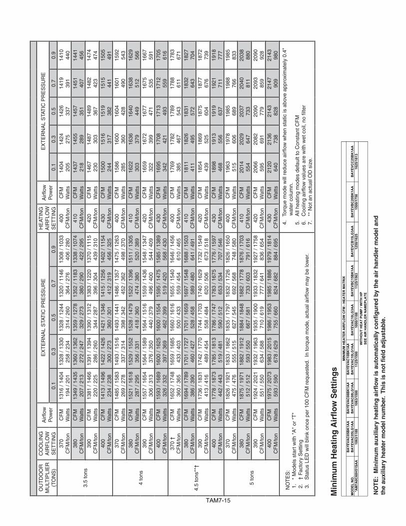
TAM715
MO
DEL
NO
.B
AYE
VAC
05B
K1A
AB
AYE
VAC
05LG
1AA
BA
YEVA
C08
BK
1AA
BA
YEVA
C08
LG1A
AB
AYE
VAC
10B
K1A
AB
AYE
VAC
10LG
1AA
BA
YEVA
C10
LG3A
AB
AYE
VBC
15B
K1A
AB
AYE
VCB
15LG
3AA
BA
YEVB
C20
BK
1AA
BA
YEVC
C25
BK
1AA
*AM
7A0C
60H
51SA
A10
63/1
188
1063
/150
011
25/1
500
1000
/118
811
25/1
563
1250
/162
515
00/1
750
1625
/181
3W
ITH
OU
T H
EAT
PUM
P / W
ITH
HP
SEE
AIR
HA
ND
LER
NA
MEP
LATE
MIN
IMU
M H
EATE
R A
IRFL
OW
CFM
- H
EATE
R M
ATR
IX
Min
imu
m H
eati
ng
Air
flo
w S
etti
ng
s
O
UT
DO
OR
MU
LTIP
LIE
R(T
ON
S)
CO
OLI
NG
A
IRF
LOW
SE
TT
ING
Airfl
owP
ower
EX
TE
RN
AL
STA
TIC
PR
ES
SU
RE
HE
ATIN
G
AIR
FLO
WS
ET
TIN
G
Airfl
owP
ower
EX
TE
RN
AL
STA
TIC
PR
ES
SU
RE
0.1
0.3
0.5
0.7
0.9
0.1
0.3
0.5
0.7
0.9
3.5
tons
370
CF
M/to
nC
FM
Wat
ts13
16 /
1404
194
/ 201
1328
/ 13
3025
8 / 2
3413
28 /
1244
314
/ 260
1320
/ 11
4636
4 / 2
7613
08 /
1033
406
/ 280
400
CF
M/to
nC
FM
Wat
ts14
0420
514
2427
514
2633
714
1939
114
1044
038
0 C
FM
/ton
CF
MW
atts
1349
/ 14
3520
7 / 2
1313
60 /
1362
272
/ 247
1359
/ 12
7832
9 / 2
7313
52 /
1183
380
/ 290
1338
/ 10
7442
2 / 2
9541
0 C
FM
/ton
CF
MW
atts
1437
218
1455
289
1457
351
1451
407
1441
456
390
CF
M/to
nC
FM
Wat
ts13
81 /
1466
220
/ 225
1391
/ 13
9428
6 / 2
6013
90 /
1312
344
/ 287
1383
/ 12
2039
6 / 3
0413
70 /
1115
439
/ 310
420
CF
M/to
nC
FM
Wat
ts14
6723
014
8730
314
8936
714
8242
314
7447
440
0 C
FM
/ton
CF
MW
atts
1413
/ 14
9623
4 / 2
3814
22 /
1426
300
/ 273
1421
/ 13
4636
0 / 3
0114
15 /
1256
412
/ 319
1402
/ 11
5445
6 / 3
2543
0 C
FM
/ton
CF
MW
atts
1500
244
1516
317
1519
382
1515
441
1505
491
4 to
ns
370
CF
M/to
nC
FM
Wat
ts14
85 /
1583
269
/ 278
1493
/ 15
1633
7 / 3
1414
93 /
1441
398
/ 342
1486
/ 13
5745
2 / 3
6214
75 /
1263
498
/ 370
400
CF
M/to
nC
FM
Wat
ts15
8628
516
0036
016
0442
816
0149
015
9254
338
0 C
FM
/ton
CF
MW
atts
1521
/ 16
1828
7 / 2
9515
29 /
1552
356
/ 331
1528
/ 14
7941
8 / 3
6015
22 /
1396
474
/ 380
1511
/ 13
0552
0 / 3
8941
0 C
FM
/ton
CF
MW
atts
1622
303
1636
379
1640
449
1638
512
1629
566
390
CF
M/to
nC
FM
Wat
ts15
57 /
1654
306
/ 313
1564
/ 15
8937
6 / 3
5015
64 /
1516
440
/ 379
1559
/ 14
3649
6 / 4
0015
48 /
1347
544
/ 409
420
CF
M/to
nC
FM
Wat
ts16
5932
216
7239
916
7747
116
7553
516
6759
140
0 C
FM
/ton
CF
MW
atts
1593
/ 16
8932
6 / 3
3216
00 /
1625
397
/ 369
1600
/ 15
5446
2 / 3
9915
95 /
1475
519
/ 420
1585
/ 13
8956
8 / 4
3043
0 C
FM
/ton
CF
MW
atts
1695
342
1708
421
1713
493
1712
559
1705
616
4.5
tons
**†
370
†C
FM
/ton
CF
MW
atts
1652
/ 17
4836
0 / 3
6516
59 /
1685
433
/ 403
1660
/ 16
1650
0 / 4
3316
55 /
1540
559
/ 454
1646
/ 14
5661
0 / 4
6540
0 C
FM
/ton
CF
MW
atts
1769
385
1782
467
1789
543
1788
611
1783
671
380
CF
M/to
nC
FM
Wat
ts16
94 /
1789
386
/ 390
1701
/ 17
2746
0 / 4
2717
01 /
1659
528
/ 458
1697
/ 15
4858
9 / 4
8016
88 /
1503
641
/ 491
410
CF
M/to
nC
FM
Wat
ts18
1141
118
2649
518
3157
218
3264
318
2770
439
0 C
FM
/ton
CF
MW
atts
1736
/ 18
3141
3 / 4
1617
42 /
1770
489
/ 454
1744
/ 17
0355
8 / 4
8417
40 /
1629
620
/ 506
1732
/ 15
4967
3 / 5
1842
0 C
FM
/ton
CF
MW
atts
1854
439
1869
525
1875
604
1877
676
1872
739
400
CF
M/to
nC
FM
Wat
ts17
78 /
1873
442
/ 443
1785
/ 18
1351
9 / 4
8117
86 /
1747
590
/ 512
1783
/ 16
7565
3 / 5
3417
76 /
1597
707
/ 546
430
CF
M/to
nC
FM
Wat
ts18
9846
819
1355
619
1963
719
2171
119
1877
7
5 to
ns
370
CF
M/to
nC
FM
Wat
ts18
26 /
1921
475
/ 476
1833
/ 18
6255
5 / 5
1518
35 /
1797
627
/ 545
1832
/ 17
2669
2 / 5
6818
26 /
1650
748
/ 580
400
CF
M/to
nC
FM
Wat
ts19
6351
519
7860
619
8568
919
8876
619
8583
338
0 C
FM
/ton
CF
MW
atts
1875
/ 19
7151
2 / 5
1218
82 /
1912
593
/ 550
1884
/ 18
4866
7 / 5
8118
82 /
1778
733
/ 603
1876
/ 17
0379
1 / 6
1641
0 C
FM
/ton
CF
MW
atts
2014
554
2029
647
2037
733
2040
811
2038
880
390
CF
M/to
nC
FM
Wat
ts19
24 /
2021
551
/ 550
1932
/ 19
6363
4 / 5
8819
35 /
1900
710
/ 619
1933
/ 18
3277
7 / 6
4119
27 /
1758
836
/ 654
420
CF
M/to
nC
FM
Wat
ts20
6659
520
8269
120
9077
920
9385
920
9092
840
0 C
FM
/ton
CF
MW
atts
1975
/ 20
7359
3 / 5
9019
83 /
2015
678
/ 629
1986
/ 19
5375
5 / 6
6019
85 /
1886
824
/ 682
1979
/ 18
1488
4 / 6
9543
0 C
FM
/ton
CF
MW
atts
2120
640
2136
738
2143
828
2147
909
2143
980
NO
TE
S:
1.
* M
odel
s st
art w
ith "
A"
or "
T"
2.
† F
acto
ry S
ettin
g3
.S
tatu
sLE
Dw
illb
link
once
per
100
CF
Mr
eque
sted
.In
torq
uem
ode,
act
uala
irflow
may
be
low
er.
4.
Tor
que
mod
ew
illr
educ
eai
rflow
whe
nst
atic
isa
bove
app
roxi
mat
ely
0.4"
w
ater
col
umn.
5.
All
heat
ing
mod
es d
efau
lt to
Con
stan
t CF
M6
.C
oolin
gai
rflow
val
ues
are
with
wet
coi
l,no
filte
r 7
. *
* N
ot a
n ac
tual
OD
siz
e.
NO
TE
: M
inim
um
au
xilia
ry h
eati
ng
air
flo
w is
au
tom
atic
ally
co
nfi
gu
red
by
the
air
han
dle
r m
od
el a
nd
th
e au
xilia
ry h
eate
r m
od
el n
um
ber
. T
his
is n
ot
fiel
d a
dju
stab
le.
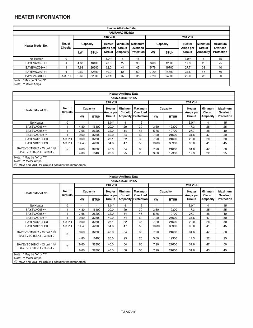
TAM716
kW BTUH kW BTUH
No Heater 0 - - 3.0** 4 15 - - 3.0** 4 15BAYEVAC05++1 1 4.80 16400 20.0 29 30 3.60 12300 17.3 25 25BAYEVAC08++1 1 7.68 26200 32.0 44 45 5.76 19700 27.7 38 40BAYEVAC10++1 1 9.60 32800 40.0 54 60 7.20 24600 34.6 47 50BAYEVAC10LG3 1-3 PH 9.60 32800 23.1 32 35 7.20 24600 20.0 28 30
*AM7A0A24H21SA
Note: * May be "A" or "T" Note: ** Motor Amps
208 Volt
Capacity Heater Amps per
Circuit
MinimumCircuit
Ampacity
MaximumOverload
Protection
Heater Model No. Capacity Minimum Circuit
Ampacity
MaximumOverload
Protection
240 Volt
HeaterAmps per
Circuit
No. of Circuits
Heater Attribute Data
kW BTUH kW BTUH
No Heater 0 - - 3.0** 4 15 - - 3.0** 4 15BAYEVAC05++1 1 4.80 16400 20.0 29 30 3.60 12300 17.3 25 25BAYEVAC08++1 1 7.68 26200 32.0 44 45 5.76 19700 27.7 38 40BAYEVAC10++1 1 9.60 32800 40.0 54 60 7.20 24600 34.6 47 50BAYEVAC10LG3 1-3 PH 9.60 32800 23.1 32 35 7.20 24600 20.0 28 30BAYEVBC15LG3 1-3 PH 14.40 42000 34.6 47 50 10.80 36900 30.0 41 45
9.60 32800 40.0 54 60 7.20 24600 34.6 47 504.80 16400 20.0 25 25 3.60 12300 17.3 22 25
208 Volt
Capacity Heater Amps per
Circuit
MinimumCircuit
Ampacity
MaximumOverload
Protection
Capacity
Note: * May be "A" or "T" Note: ** Motor Amps1 MCA and MOP for circuit 1 contains the motor amps
HeaterAmps per
Circuit
Heater Attribute Data
BAYEVBC15BK1 - Circuit 1 1BAYEVBC15BK1 - Circuit 2
MinimumCircuit
Ampacity
MaximumOverload
Protection
*AM7A0B30H21SA
Heater Model No. No. of Circuits
240 Volt
2
kW BTUH kW BTUH
No Heater 0 - - 3.0** 4 15 - - 3.0** 4 15BAYEVAC05++1 1 4.80 16400 20.0 29 30 3.60 12300 17.3 25 25BAYEVAC08++1 1 7.68 26200 32.0 44 45 5.76 19700 27.7 38 40BAYEVAC10++1 1 9.60 32800 40.0 54 60 7.20 24600 34.6 47 50BAYEVAC10LG3 1-3 PH 9.60 32800 23.1 32 35 7.20 24600 20.0 28 30BAYEVBC15LG3 1-3 PH 14.40 42000 34.6 47 50 10.80 36900 30.0 41 45
9.60 32800 40.0 54 60 7.20 24600 34.6 47 50
4.80 16400 20.0 25 25 3.60 12300 17.3 22 25
9.60 32800 40.0 54 60 7.20 24600 34.6 47 50
9.60 32800 40.0 50 50 7.20 24600 34.6 43 45 Note: * May be "A" or "T" Note: ** Motor Amps1 MCA and MOP for circuit 1 contains the motor amps
BAYEVBC15BK1 - Circuit 1 1BAYEVBC15BK1 - Circuit 2
BAYEVBC20BK1 - Circuit 1 1BAYEVBC20BK1 - Circuit 2
HeaterAmps per
Circuit
MinimumCircuit
Ampacity
MaximumOverload
Protection
MaximumOverload
Protection
Capacity Heater Amps per
Circuit
Heater Attribute Data
MinimumCircuit
Ampacity
2
2
*AM7A0C36H31SA
Heater Model No. No. of Circuits
240 Volt 208 Volt
Capacity
HEATER INFORMATION
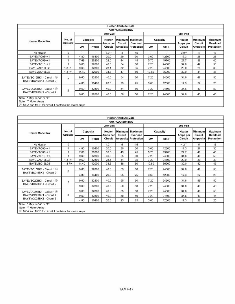
TAM717
kW BTUH kW BTUH
No Heater 0 - - 3.0** 4 15 - - 3.0** 4 15BAYEVAC05++1 1 4.80 16400 20.0 29 30 3.60 12300 17.3 25 25BAYEVAC08++1 1 7.68 26200 32.0 44 45 5.76 19700 27.7 38 40BAYEVAC10++1 1 9.60 32800 40.0 54 60 7.20 24600 34.6 47 50BAYEVAC10LG3 1-3 PH 9.60 32800 23.1 32 35 7.20 24600 20.0 28 30BAYEVBC15LG3 1-3 PH 14.40 42000 34.6 47 50 10.80 36900 30.0 41 45
9.60 32800 40.0 54 60 7.20 24600 34.6 47 50
4.80 16400 20.0 25 25 3.60 12300 17.3 22 25
9.60 32800 40.0 54 60 7.20 24600 34.6 47 50
9.60 32800 40.0 50 50 7.20 24600 34.6 43 45 Note: * May be "A" or "T" Note: ** Motor Amps1 MCA and MOP for circuit 1 contains the motor amps
Heater Attribute Data*AM7A0C42H31SA
Heater Model No. No. of Circuits
240 Volt 208 Volt
Capacity Heater Amps per
Circuit
MinimumCircuit
Ampacity
MaximumOverload
Protection
Capacity Heater Amps per
Circuit
MinimumCircuit
Ampacity
MaximumOverload
Protection
BAYEVBC15BK1 - Circuit 1 1BAYEVBC15BK1 - Circuit 2
BAYEVBC20BK1 - Circuit 1 1BAYEVBC20BK1 - Circuit 2 2
2
kW BTUH kW BTUH
No Heater 0 - - 4.2** 5 15 - - 4.2** 5 15BAYEVAC05++1 1 4.80 16400 20.0 30 30 3.60 12300 17.3 27 30BAYEVAC08++1 1 7.68 26200 32.0 45 45 5.76 19700 27.7 40 40BAYEVAC10++1 1 9.60 32800 40.0 55 60 7.20 24600 34.6 49 50BAYEVAC10LG3 1-3 PH 9.60 32800 23.1 34 35 7.20 24600 20.0 30 30BAYEVBC15LG3 1-3 PH 14.40 42000 34.6 48 50 10.80 36900 30.0 42 45
9.60 32800 40.0 55 60 7.20 24600 34.6 49 50
4.80 16400 20.0 25 25 3.60 12300 17.3 22 25
9.60 32800 40.0 55 60 7.20 24600 34.6 49 50
9.60 32800 40.0 50 50 7.20 24600 34.6 43 45
9.60 32800 40.0 55 60 7.20 24600 34.6 49 50
9.60 32800 40.0 50 50 7.20 24600 34.6 43 45
4.80 16400 20.0 25 25 3.60 12300 17.3 22 25
BAYEVCC25BK1 - Circuit 1 1BAYEVCC25BK1 - Circuit 2BAYEVCC25BK1 - Circuit 3
Note: * May be "A" or "T" Note: ** Motor Amps1 MCA and MOP for circuit 1 contains the motor amps
Heater Attribute Data*AM7A0C48H41SA
MinimumCircuit
Ampacity
MaximumOverload
Protection
Capacity Heater Amps per
Circuit
MinimumCircuit
Ampacity
MaximumOverload
Protection
BAYEVBC15BK1 - Circuit 1 1BAYEVBC15BK1 - Circuit 2
BAYEVBC20BK1 - Circuit 1 1BAYEVBC20BK1 - Circuit 2
Heater Model No. No. of Circuits
240 Volt 208 Volt
Capacity Heater Amps per
Circuit
2
2
3
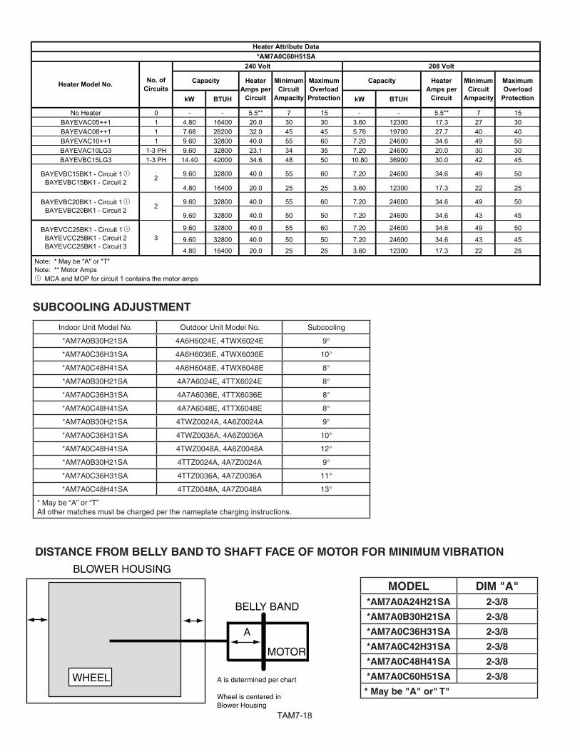
TAM718
DISTANCE FROM BELLY BAND TO SHAFT FACE OF MOTOR FOR MINIMUM VIBRATION
WHEEL
BLOWER HOUSING
BELLY BAND
MOTOR
A
A is determined per chart
Wheel is centered inBlower Housing
MODEL DIM "A"*AM7A0A24H21SA 2-3/8
*AM7A0B30H21SA 2-3/8
*AM7A0C36H31SA 2-3/8
*AM7A0C42H31SA 2-3/8
*AM7A0C48H41SA 2-3/8
*AM7A0C60H51SA 2-3/8
* May be "A" or" T"
SUBCOOLING ADJUSTMENT
Indoor Unit Model No. Outdoor Unit Model No. Subcooling
*AM7A0B30H21SA 4A6H6024E, 4TWX6024E 9°
*AM7A0C36H31SA 4A6H6036E, 4TWX6036E 10°
*AM7A0C48H41SA 4A6H6048E, 4TWX6048E 8°
*AM7A0B30H21SA 4A7A6024E, 4TTX6024E 8°
*AM7A0C36H31SA 4A7A6036E, 4TTX6036E 8°
*AM7A0C48H41SA 4A7A6048E, 4TTX6048E 8°
*AM7A0B30H21SA 4TWZ0024A, 4A6Z0024A 9°
*AM7A0C36H31SA 4TWZ0036A, 4A6Z0036A 10°
*AM7A0C48H41SA 4TWZ0048A, 4A6Z0048A 12°
*AM7A0B30H21SA 4TTZ0024A, 4A7Z0024A 9°
*AM7A0C36H31SA 4TTZ0036A, 4A7Z0036A 11°
*AM7A0C48H41SA 4TTZ0048A, 4A7Z0048A 13°
* May be “A” or “T”All other matches must be charged per the nameplate charging instructions.
kW BTUH kW BTUH
No Heater 0 - - 5.5** 7 15 - - 5.5** 7 15BAYEVAC05++1 1 4.80 16400 20.0 30 30 3.60 12300 17.3 27 30BAYEVAC08++1 1 7.68 26200 32.0 45 45 5.76 19700 27.7 40 40BAYEVAC10++1 1 9.60 32800 40.0 55 60 7.20 24600 34.6 49 50BAYEVAC10LG3 1-3 PH 9.60 32800 23.1 34 35 7.20 24600 20.0 30 30BAYEVBC15LG3 1-3 PH 14.40 42000 34.6 48 50 10.80 36900 30.0 42 45
9.60 32800 40.0 55 60 7.20 24600 34.6 49 50
4.80 16400 20.0 25 25 3.60 12300 17.3 22 25
9.60 32800 40.0 55 60 7.20 24600 34.6 49 50
9.60 32800 40.0 50 50 7.20 24600 34.6 43 45
9.60 32800 40.0 55 60 7.20 24600 34.6 49 50
9.60 32800 40.0 50 50 7.20 24600 34.6 43 45
4.80 16400 20.0 25 25 3.60 12300 17.3 22 25
BAYEVCC25BK1 - Circuit 1 1BAYEVCC25BK1 - Circuit 2BAYEVCC25BK1 - Circuit 3
Note: * May be "A" or "T" Note: ** Motor Amps1 MCA and MOP for circuit 1 contains the motor amps
MinimumCircuit
Ampacity
MaximumOverload
Protection
BAYEVBC15BK1 - Circuit 1 1BAYEVBC15BK1 - Circuit 2
BAYEVBC20BK1 - Circuit 1 1BAYEVBC20BK1 - Circuit 2
Heater Model No. No. of Circuits
240 Volt 208 Volt
Capacity Heater Amps per
Circuit
Heater Attribute Data*AM7A0C60H51SA
Capacity Heater Amps per
Circuit
MinimumCircuit
Ampacity
MaximumOverload
Protection
2
3
2
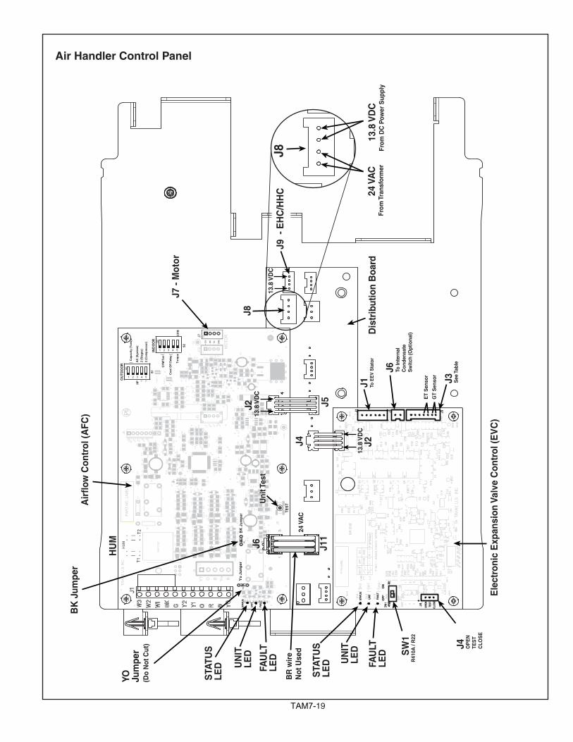
TAM719
Pb
FAU
LT
UN
IT
4833
321716
164 49
TRAN
EU
.S.I
NC
.
VDDPGD
MCLRVSS PGC
3.3V SCLSDA GND
HUM
5V
MO
TOR
GN
D
RX
TX
+12V
PAR
TNO
.LAB
EL
BAR
CO
DE
1 2 3 4 5
1 2 3 4 5
STA
TUS
+12V
+13.
8V
C60
C59R
57R
58
R64
R65
R76
R78
C20
C28
C55
S3
R11
0
R59
R41
R68
C40
R10
8
R93
R10
9
R12
R55
R23
R20
R49
R13 R14
D23
D19
D18
C46
C39
C6
C23
R80
R71
R67
R52
R75
R72
Q2
C41
R61
Q6
Q7
R1
R33
R34
J4
Q1
X1
U5
U4
U3
TZ2
T2T1
R99
R98
R97
R60
R96
R95
R21
R91
R87
R88
R70
R86
R83
R81
R66
R79
R77
R54
R10
3R
106
R4
R10
4
R51 R53
R48
R47
R44
R42
R39
R82
R37
R35
R31
R30
R74
R89
R25
R18
R19
R10 R
9
R8
R3
R2
R5
R7
Q8
Q4
PTC1
MO
V1
L2 L3
K1
J3
J6
J9
D36
D35
D34
D1
D22
D29
D25
D24
D7
D4
D2
D28
C57
C54
C56
C51
C49
C48
C47
C52
C43
C42
C36
C35
C34
C31
C30
C29
C13
C7
C3
C2
C1
U1
C58
R10
5
C50
U2
J7
R24
R17
D6
D3
D14 D
17
RN
ET1
RN
ET2
R73
1
J8
Yo RBOY1
J1 W2
W1
R63
R62
R56
D21
D20
C32
C33
R38
R36
R16
R15
R32
R11
R28
R27
R26
D13
D12D
5D
11
D10
C24
C25
C4
C5
C16
C17
D8
R50
R45
R85
R84
D16
D15
D31
D30
C26
C27
C44
C45
D32
D33
R94
R10
0
R10
1
R107
R29
K2
R6
C53
C22
C19
C15
C12
C9
C8
C11
C14
C18
C21
D26
R69
C37
C38
C10
D9
L1
R10
2
D27
R40
R22
R46
R43
Q3
Q5
BK
Jum
per
YoJu
mpe
rW
2W
1
TEST
J13
11HP
2(C
ompr
esso
r)2
(Sta
ges)
AC
(Sys
tem
)
}Cap
acity
(Ton
s)
OUT
DOO
R
}
Torq
ue
CFM
/Ton
Coo
lOff
Dela
y
}IND
OO
R
CFM
S1on
on
S2
J4
J3J1 J6
TEST
CLOS
E
410
FAUL
T
UNIT
22
OPEN
STAT
US
FAUL
T
UNIT
STAT
US OFF
ON
J2J4
J5J2
J7 -
Mot
or
J8
J9 -
EH
C/H
HC
J4J3
J6
J1
J11
BR
wir
e N
ot U
sed
Uni
t Tes
t
SW
1
STA
TUS
LE
D
J6
FAU
LT
LED
To E
EV
Sta
tor
To In
tern
al
Con
dens
ate
Sw
itch
(Opt
iona
l)R
410A
/ R
22
OP
EN
TES
TC
LOS
E
GT
Sen
sor
See
Tab
le
ET
Sen
sor
UN
IT
LED
STA
TUS
LE
D
Air
flow
Con
trol
(AFC
)
Dis
trib
utio
n B
oard
24 V
AC
From
Tra
nsfo
rmer
24 V
AC
From
DC
Pow
er S
uppl
y13
.8 V
DC
13.8
VD
C
Ele
ctro
nic
Exp
ansi
on V
alve
Con
trol
(EV
C)
FAU
LT
LED
UN
IT
LED
HU
M
BK
Jum
per
YO Jum
per
(Do
Not
Cut
)
13.8
VD
C
13.8
VD
C
J8
Air Handler Control Panel
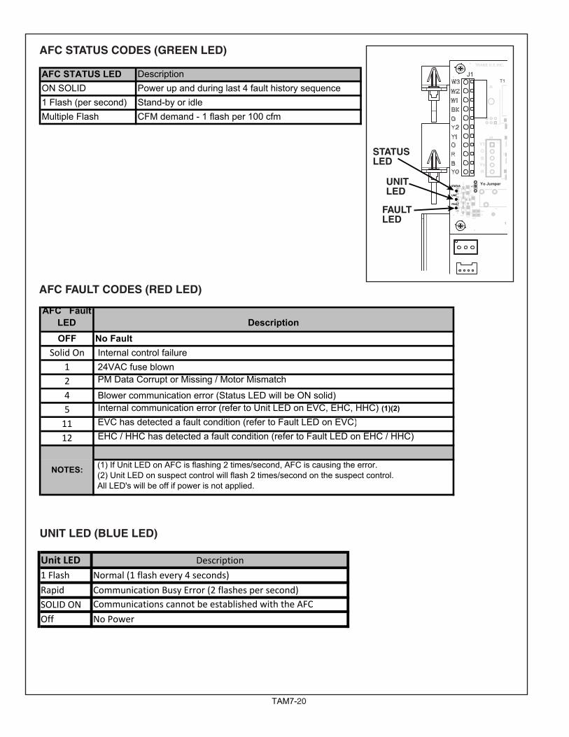
TAM720
AFC STATUS LED DescriptionON SOLID Power up and during last 4 fault history sequence1 Flash (per second) Stand-by or idleMultiple Flash CFM demand - 1 flash per 100 cfm
AFC STATUS CODES (GREEN LED)
AFC FAULT CODES (RED LED)
FAULT
UNIT
TRANE U.S. INC. HUM
BAR CODE
STATUS
R55R49
D18
R80
T2T1
R60
R70
R66
R82
R74
R7
Q8
J6
J9
D22
D25
D28
C52
R73
1
J8
YoR
BOY1
J1
W2W1
R63R62R56
D21D20 C32C33
R38
R16R28 R27R26
D12
D5D11
D10
C16C17
R50R45
R85 R84
D16D15
D31D30
C26C27
C44C45
D32
D33
R94
R100
R101
K2
R69
DH JumperYo JumperW2
W1
FAULT
UNIT
STATUS
STATUS LED
FAULT LED
UNIT LED
UNIT LED (BLUE LED)
Unit LED1 Flash
Rapid
OffSOLID ON
Description
Normal (1 flash every 4 seconds)
Communication Busy Error (2 flashes per second)
No Power
Communications cannot be established with the AFC
AFC FaultLED DescriptionOFF No Fault
Solid On Internal control failure 1 24VAC fuse blown2 PM Data Corrupt or Missing / Motor Mismatch
4 Blower communication error (Status LED will be ON solid)5 Internal communication error (refer to Unit LED on EVC, EHC, HHC) (1)(2)
11 EVC has detected a fault condition (refer to Fault LED on EVC)
12 EHC / HHC has detected a fault condition (refer to Fault LED on EHC / HHC)
(1) If Unit LED on AFC is flashing 2 times/second, AFC is causing the error. (2) Unit LED on suspect control will flash 2 times/second on the suspect control. All LED's will be off if power is not applied.
NOTES:
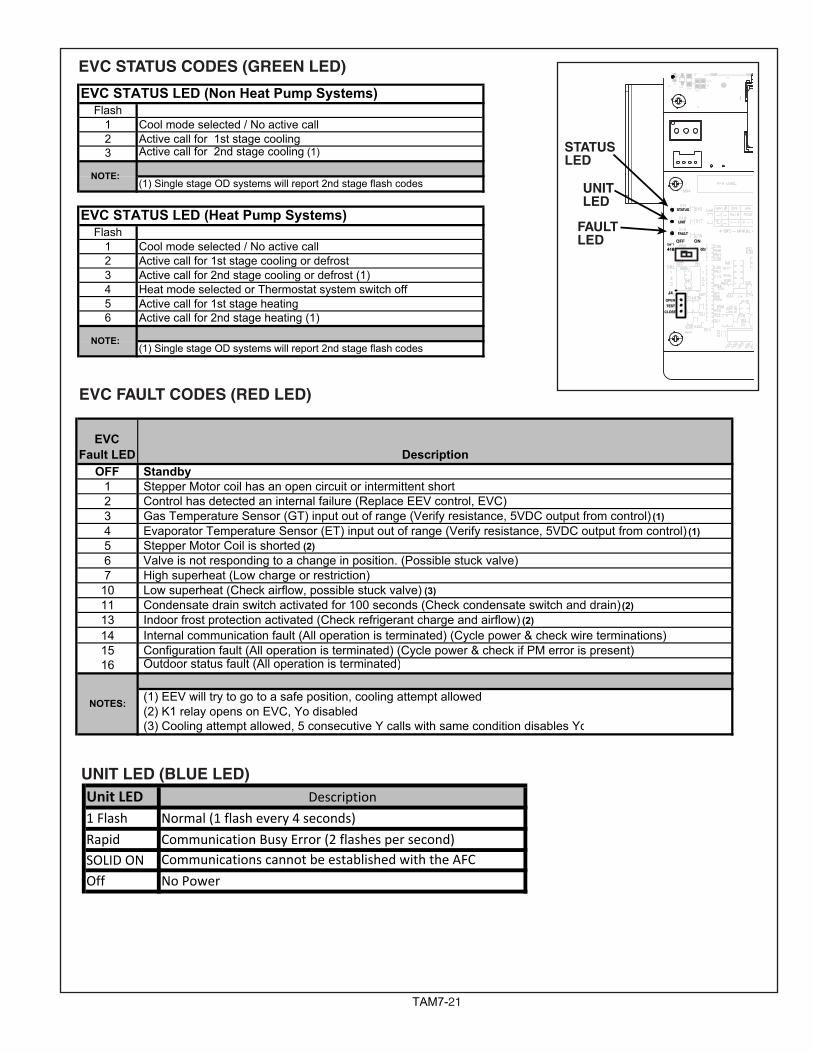
TAM721
EVC FAULT CODES (RED LED)
EVC STATUS CODES (GREEN LED) FAULT
R80
R70
D
D28R73
R100
K2
J4
TESTCLOSE
410
FAULT
UNIT
22
OPEN
STATUS
FAULT
OFF ON
STATUS LED
FAULT LED
UNIT LED
UNIT LED (BLUE LED)Unit LED1 Flash
Rapid
OffSOLID ON
Description
Normal (1 flash every 4 seconds)
Communication Busy Error (2 flashes per second)
No Power
Communications cannot be established with the AFC
EVCFault LED Description
OFF Standby1 Stepper Motor coil has an open circuit or intermittent short2 Control has detected an internal failure (Replace EEV control, EVC)3 Gas Temperature Sensor (GT) input out of range (Verify resistance, 5VDC output from control) (1)4 Evaporator Temperature Sensor (ET) input out of range (Verify resistance, 5VDC output from control) (1)5 Stepper Motor Coil is shorted (2)6 Valve is not responding to a change in position. (Possible stuck valve)7 High superheat (Low charge or restriction)10 Low superheat (Check airflow, possible stuck valve) (3)11 Condensate drain switch activated for 100 seconds (Check condensate switch and drain) (2)13 Indoor frost protection activated (Check refrigerant charge and airflow) (2)14 Internal communication fault (All operation is terminated) (Cycle power & check wire terminations)15 Configuration fault (All operation is terminated) (Cycle power & check if PM error is present)16 Outdoor status fault (All operation is terminated)
(1) EEV will try to go to a safe position, cooling attempt allowed (2) K1 relay opens on EVC, Yo disabled (3) Cooling attempt allowed, 5 consecutive Y calls with same condition disables Yo
NOTES:
EVC STATUS LED (Non Heat Pump Systems)Flash
1 Cool mode selected / No active call 2 Active call for 1st stage cooling3 Active call for 2nd stage cooling (1)
(1) Single stage OD systems will report 2nd stage flash codes
EVC STATUS LED (Heat Pump Systems)Flash
1 Cool mode selected / No active call2 Active call for 1st stage cooling or defrost3 Active call for 2nd stage cooling or defrost (1)4 Heat mode selected or Thermostat system switch off 5 Active call for 1st stage heating6 Active call for 2nd stage heating (1)
(1) Single stage OD systems will report 2nd stage flash codes
NOTE:
NOTE:
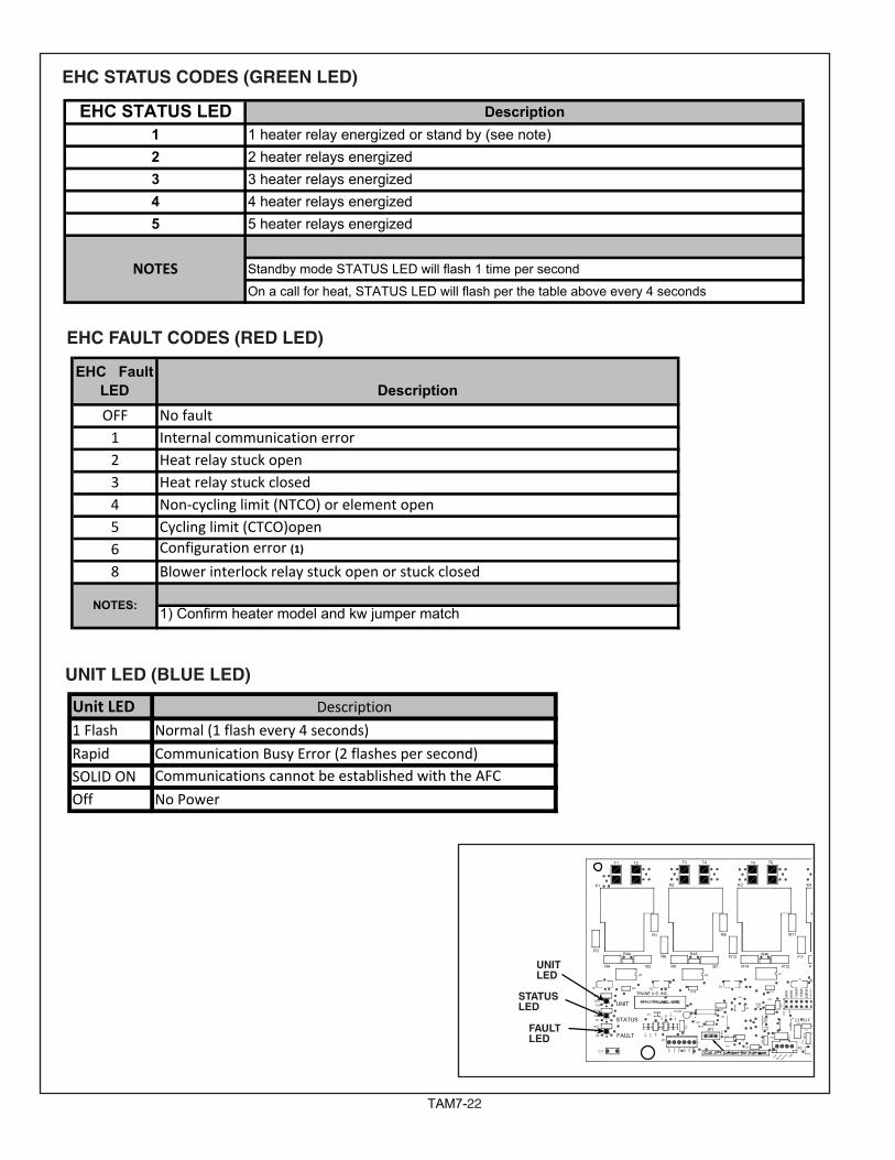
TAM722
EHC STATUS CODES (GREEN LED)
UNIT LED (BLUE LED)
EHC FAULT CODES (RED LED)
EHC Fault LED DescriptionOFF No fault1 Internal communication error2 Heat relay stuck open3 Heat relay stuck closed4 Non‐cycling limit (NTCO) or element open5 Cycling limit (CTCO)open6 Configuration error (1)
8 Blower interlock relay stuck open or stuck closed
1) Confirm heater model and kw jumper matchNOTES:
EHC STATUS LED12345 5 heater relays energized
Standby mode STATUS LED will flash 1 time per second
On a call for heat, STATUS LED will flash per the table above every 4 seconds
NOTES
Description1 heater relay energized or stand by (see note)2 heater relays energized3 heater relays energized4 heater relays energized
Unit LED1 Flash
Rapid
OffSOLID ON
Description
Normal (1 flash every 4 seconds)
Communication Busy Error (2 flashes per second)
No Power
Communications cannot be established with the AFC
20KW
15KW
10KW
8KW
5KW
PAR
K
TRANE U.S. INC.
FAULT
STATUS
UNIT
T8T7T6
13.8V
DATAA
DATAB
GND
+5V
+13.8V
GND
25KW
R73
R72
R71
R70
MO
V1
D23
D22
R69
R6 6
JP1C13
R65 R
64
R63R62
R61
R60
R19
R18
D8
D7
T11
T9
R56
R55
R5 4
R53
R52
R51
R50
R49
R48R47R46R45R44
R37R36
R30
R29
D20
D19
D17
D16
D15D14
D12
D11
D10
D9
C11
C9
P3
AU
X
PG
C
PG
D
VS
S
VD
D
MC
L R
1P1
X1
U1
T2T1
R43
R41
R39
R27
R26
R38
R33
R32
R35
R34
R28
R31
D6
D5D3D2D1
C10
C5
C7 C6
C4
C3
C8
C2
C1
P2 K6
U3
U2U4
R5R10 R15
R20 R25
U5 U6 U7 U8 U9
R40
T5T4T3 T10
T12
R14
R13
R9
R8
R7
R6
R4
R3
R2
R1
R17
R16
R12
R11
R23
R22
R21
R24
K1 K2 K3 K4 K5
R57
R58
R59
C12
D4
D21
R67
R68
D24 D25STATUS LED
FAULT LED
UNIT LED
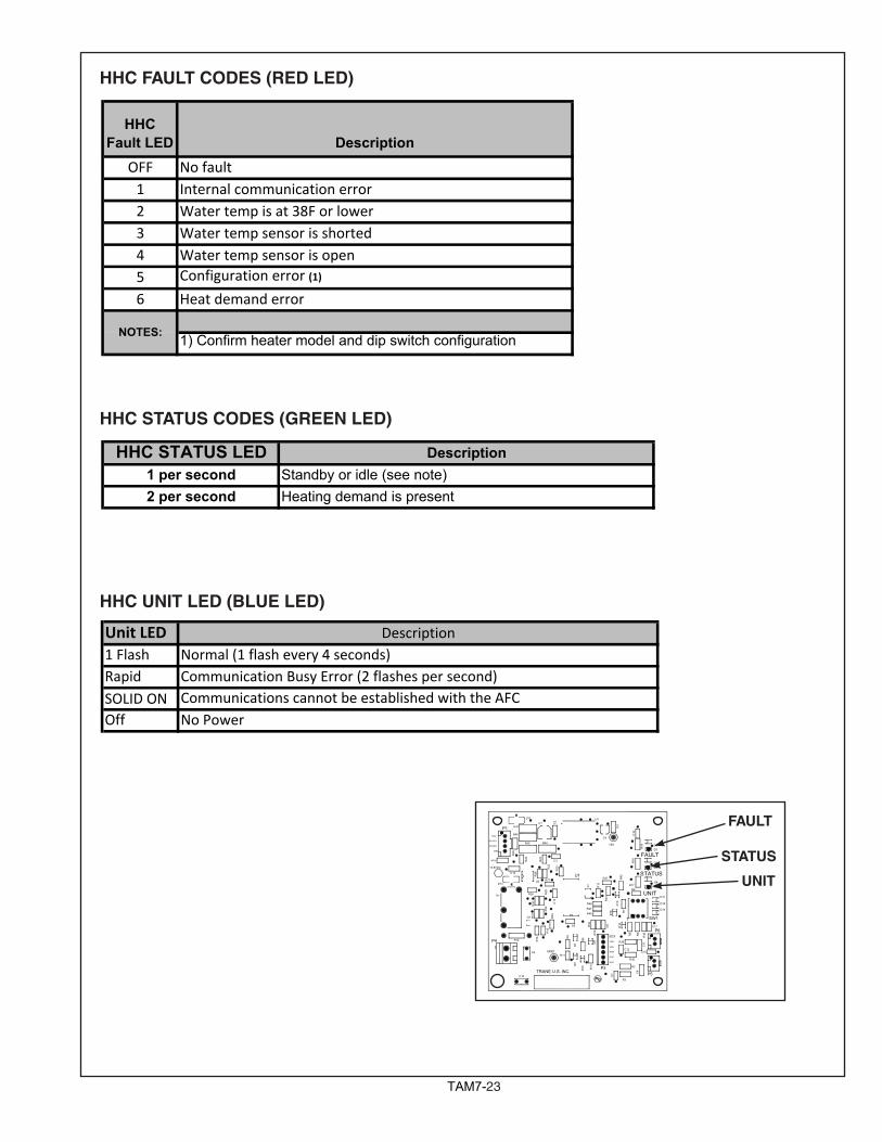
TAM723
HHCFault LED Description
OFF No fault1 Internal communication error2 Water temp is at 38F or lower3 Water temp sensor is shorted4 Water temp sensor is open5 Configuration error (1)
6 Heat demand error
1) Confirm heater model and dip switch configurationNOTES:
HHC STATUS CODES (GREEN LED)
HHC FAULT CODES (RED LED)
HHC UNIT LED (BLUE LED)
UNIT
STATUS
FAULT
GND
13.8VDC
+5V
.
TRANE U.S. INC.
UNIT
STATUS
FAULT
13.8V
DATA A
DATA B
GND
Pb
D18
D16
D14
D12
D15
D17
R48
R47
R46
R45 R44
MOV1
1 SW1
K1
AUX
PGC
PGD
VSS
VDD
MCLR.
P3
C161
P4
X1
U3
U2
U1
R39
R37
R36
R35
R34
R33
R32
R3 1
R30
R29
R28
R27
R26
R25
R24
R2 3
R22
R20
R19
R18
R17
R16
R15
R14
R13
R12
R11
R10
R9
R8
R7
R6
R5
R4
R3
R2
R1
Q1
P6
P5
P1
D13
D11
D10
D9
D8
D7
D6
D5
D4
D3
D2
D1
C13
C12
C11
C9
C8
C7 C
6
C5
C4
C3
C2
C1
C14
R40
R41
C10
C15
C17
R42
R43
HHC STATUS LED1 per second2 per second
DescriptionStandby or idle (see note)Heating demand is present
Unit LED1 FlashRapid
Off No Power
DescriptionNormal (1 flash every 4 seconds)Communication Busy Error (2 flashes per second)
SOLID ON Communications cannot be established with the AFC
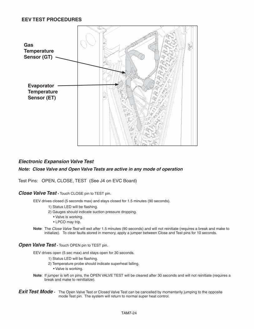
TAM724
Electronic Expansion Valve Test
Note: Close Valve and Open Valve Tests are active in any mode of operation
Test Pins: OPEN, CLOSE, TEST (See J4 on EVC Board)
Close Valve Test - Touch CLOSE pin to TEST pin.
EEV drives closed (5 seconds max) and stays closed for 1.5 minutes (90 seconds).
1)StatusLEDwillbeflashing. 2) Gauges should indicate suction pressure dropping.
•Valveisworking.•LPCOmaytrip.
Note: The Close Valve Test will exit after 1.5 minutes (90 seconds) and will not reinitiate (requires a break and make to initialize). To clear faults stored in memory, apply a jumper between Close and Test pins for 10 seconds.
Open Valve Test - Touch OPEN pin to TEST pin.
EEV drives open (5 sec max) and stays open for 30 seconds.
1)StatusLEDwillbeflashing. 2) Temperature probe should indicate superheat falling.
•Valveisworking.
Note: If jumper is left on pins, the OPEN VALVE TEST will be cleared after 30 seconds and will not reinitiate (requires a break and make to reinitialize).
Exit Test Mode - The Open Valve Test or Closed Valve Test can be cancelled by momentarily jumping to the opposite mode Test pin. The system will return to normal super heat control.
EEV TEST PROCEDURES
EvaporatorTemperature Sensor (ET)
Gas Temperature Sensor (GT)
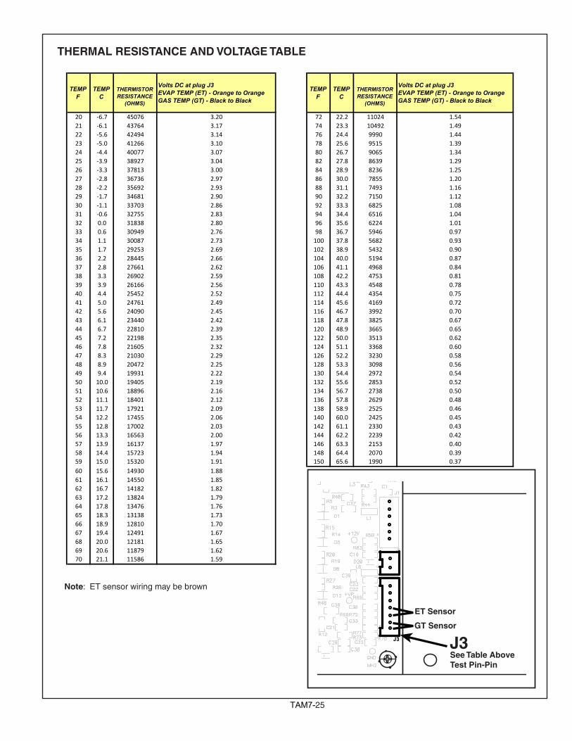
TAM725
TEMPF
TEMPC
THERMISTORRESISTANCE
(OHMS)
Volts DC at plug J3EVAP TEMP (ET) - Orange to OrangeGAS TEMP (GT) - Black to Black
TEMPF
TEMPC
THERMISTORRESISTANCE
(OHMS)
Volts DC at plug J3EVAP TEMP (ET) - Orange to OrangeGAS TEMP (GT) - Black to Black
20 ‐6.7 45076 3.20 72 22.2 11024 1.5421 ‐6.1 43764 3.17 74 23.3 10492 1.4922 ‐5.6 42494 3.14 76 24.4 9990 1.4423 ‐5.0 41266 3.10 78 25.6 9515 1.3924 ‐4.4 40077 3.07 80 26.7 9065 1.3425 ‐3.9 38927 3.04 82 27.8 8639 1.2926 ‐3.3 37813 3.00 84 28.9 8236 1.2527 ‐2.8 36736 2.97 86 30.0 7855 1.2028 ‐2.2 35692 2.93 88 31.1 7493 1.1629 ‐1.7 34681 2.90 90 32.2 7150 1.1230 ‐1.1 33703 2.86 92 33.3 6825 1.0831 ‐0.6 32755 2.83 94 34.4 6516 1.0432 0.0 31838 2.80 96 35.6 6224 1.0133 0.6 30949 2.76 98 36.7 5946 0.9734 1.1 30087 2.73 100 37.8 5682 0.9335 1.7 29253 2.69 102 38.9 5432 0.9036 2.2 28445 2.66 104 40.0 5194 0.8737 2.8 27661 2.62 106 41.1 4968 0.8438 3.3 26902 2.59 108 42.2 4753 0.8139 3.9 26166 2.56 110 43.3 4548 0.7840 4.4 25452 2.52 112 44.4 4354 0.7541 5.0 24761 2.49 114 45.6 4169 0.7242 5.6 24090 2.45 116 46.7 3992 0.7043 6.1 23440 2.42 118 47.8 3825 0.6744 6.7 22810 2.39 120 48.9 3665 0.6545 7.2 22198 2.35 122 50.0 3513 0.6246 7.8 21605 2.32 124 51.1 3368 0.6047 8.3 21030 2.29 126 52.2 3230 0.5848 8.9 20472 2.25 128 53.3 3098 0.5649 9.4 19931 2.22 130 54.4 2972 0.5450 10.0 19405 2.19 132 55.6 2853 0.5251 10.6 18896 2.16 134 56.7 2738 0.5052 11.1 18401 2.12 136 57.8 2629 0.4853 11.7 17921 2.09 138 58.9 2525 0.4654 12.2 17455 2.06 140 60.0 2425 0.4555 12.8 17002 2.03 142 61.1 2330 0.4356 13.3 16563 2.00 144 62.2 2239 0.4257 13.9 16137 1.97 146 63.3 2153 0.4058 14.4 15723 1.94 148 64.4 2070 0.3959 15.0 15320 1.91 150 65.6 1990 0.3760 15.6 14930 1.8861 16.1 14550 1.8562 16.7 14182 1.8263 17.2 13824 1.7964 17.8 13476 1.7665 18.3 13138 1.7366 18.9 12810 1.7067 19.4 12491 1.6768 20.0 12181 1.6569 20.6 11879 1.6270 21.1 11586 1.59
THERMAL RESISTANCE AND VOLTAGE TABLE
J3 J3GT Sensor
See Table AboveTest Pin-Pin
ET Sensor
Note: ET sensor wiring may be brown
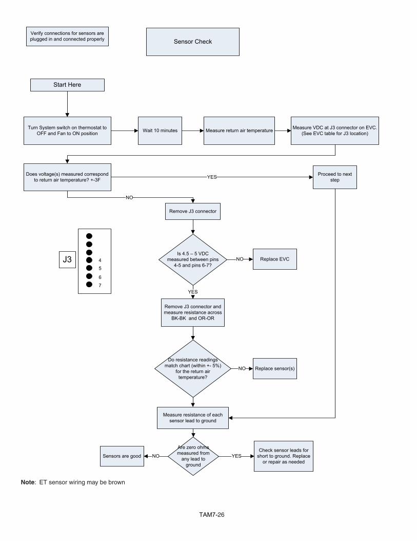
TAM726
Sensor Check
Turn System switch on thermostat to OFF and Fan to ON position Wait 10 minutes Measure return air temperature Measure VDC at J3 connector on EVC.
(See EVC table for J3 location)
Does voltage(s) measured correspond to return air temperature? +-3F
Remove J3 connector and measure resistance across
BK-BK and OR-OR
Replace EVC
Verify connections for sensors are plugged in and connected properly
NO
Start Here
Do resistance readings match chart (within +- 5%)
for the return air temperature?
Replace sensor(s)NO
YES Proceed to next step
Remove J3 connector
Is 4.5 – 5 VDC measured between pins
4-5 and pins 6-7?
YES
NO
Are zero ohms measured from
any lead to ground
Measure resistance of each sensor lead to ground
Check sensor leads for short to ground. Replace
or repair as neededYESSensors are good NO
J3
7
45
6
Note: ET sensor wiring may be brown
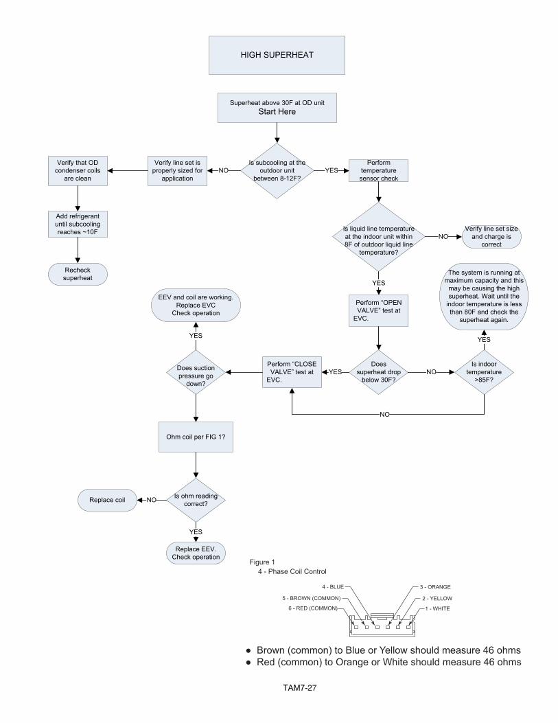
TAM727
4 - Phase Coil ControlFigure 1
4 - BLUE
5 - BROWN (COMMON)
6 - RED (COMMON)
3 - ORANGE
2 - YELLOW
1 - WHITE
● Brown (common) to Blue or Yellow should measure 46 ohms● Red (common) to Orange or White should measure 46 ohms
HIGH SUPERHEAT
Superheat above 30F at OD unitStart Here
Is subcooling at the outdoor unit
between 8-12F?
Verify line set is properly sized for
applicationNO
Verify that OD condenser coils
are clean
Add refrigerant until subcooling reaches ~10F
Recheck superheat
Is liquid line temperature at the indoor unit within 8F of outdoor liquid line
temperature?
Verify line set size and charge is
correctNO
Perform “OPEN VALVE” test at
EVC.
YES
Does superheat drop
below 30F?
Is indoor temperature
>85F?NO
Perform “CLOSE VALVE” test at
EVC. YESDoes suction
pressure go down?
EEV and coil are working. Replace EVC
Check operation
YES
YESPerform
temperature sensor check
YES
NO
The system is running at maximum capacity and this
may be causing the high superheat. Wait until the
indoor temperature is less than 80F and check the
superheat again.
Replace EEV. Check operation
Ohm coil per FIG 1?
Is ohm reading correct?
YES
Replace coil NO
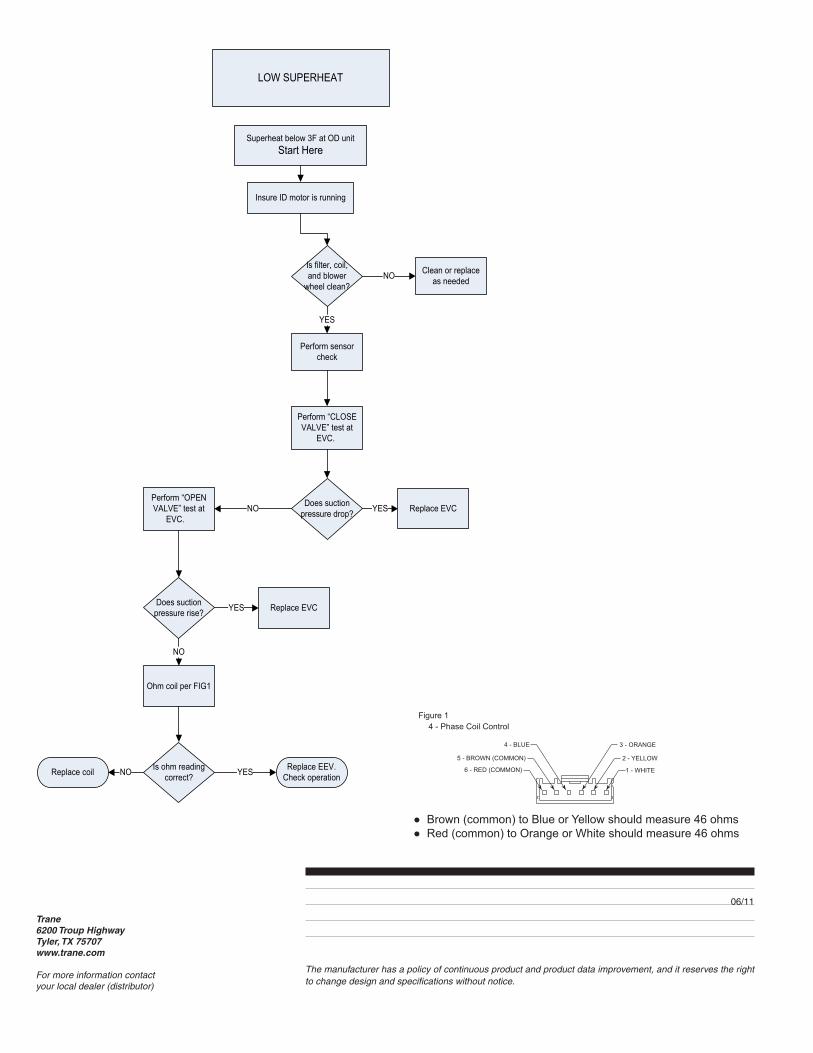
Trane6200 Troup HighwayTyler, TX 75707www.trane.com
For more information contactyour local dealer (distributor)
06/11
The manufacturer has a policy of continuous product and product data improvement, and it reserves the right to change design and specifications without notice.
LOW SUPERHEAT
Superheat below 3F at OD unitStart Here
Is filter, coil, and blower
wheel clean?
Clean or replace as neededNO
Perform sensor check
YES
Perform “CLOSE VALVE” test at
EVC.
Does suction pressure drop?
Perform “OPEN VALVE” test at
EVC.
Does suction pressure rise?
Replace EVCYES
Replace EVCYES
Replace EEV. Check operation
Ohm coil per FIG1
Is ohm reading correct? YESReplace coil NO
NO
NO
F
B
R
Insure ID motor is running
4 - Phase Coil ControlFigure 1
4 - BLUE
5 - BROWN (COMMON)
6 - RED (COMMON)
3 - ORANGE
2 - YELLOW
1 - WHITE
● Brown (common) to Blue or Yellow should measure 46 ohms● Red (common) to Orange or White should measure 46 ohms