Embed Size (px)
Citation preview
1
DISCIPLINE: ELECTRONICS & TELECOMMUNICATION
ENIGINEERING SEMESTER : V
Subject: Computer Networks & Mobile Technology
Content Developed by :
Er. Amulya Kumar Panda AMIE (India) Electronics &Telecom.,
M.E. Computer Sc. Engg. & Application,
LMISTE, MIE
2
COMPUTER NETWORKS & MOBILE TECHNOLOGY
FIFTH SEMESTER (E&TC)
CHAPTER -1
1. Network Components, Functions and Features :
1.1 Define Networking :-
In the world of computers, networking is the practice of linking two or more
computing devices together for the purpose of sharing data. Or say networks are built with a
mix of computer
A network or a networking is defined as the interconnection of a set of devices
capable of communication.
In this definition, a device can be a large computer, desktop, laptop, workstation,
cellular phone, or security system or it can also be a connecting device such as a router,
which connects the network to other networks or a switch, which connects devices together
or a modem (modulator-demodulator), which changes the form of data, and so on. These
devices in a network are connected using wired or wireless transmission media such as cable
or air.
When we connect two computers at home using a plug-and-play router, this is a
example of networking,
What is a network criterion:- A network must be able to meet a certain number of
criteria. The most important of these are performance, reliability, and security.
Performance:- Performance can be measured in many ways, including transit time
and response time. Transit time is the amount of time required for a message to travel from
one device to another. Response time is the elapsed time between an inquiry and a response.
The performance of a network depends on a number of factors, including the number of users,
the type of transmission medium, the capabilities of the connected hardware, and the
efficiency of the software. Performance is often evaluated by two networking metrics:
throughput and delay. We often need more throughput and less delay. However, these two
criteria are often contradictory. If we try to send more data to the network, we may increase
throughput but we increase the delay because of traffic congestion in the network.
3
Reliability:- In addition to accuracy of delivery, network reliability is measured by the
frequency of failure, the time it takes a link to recover from a failure, and the network's
robustness in a catastrophe.
Security:- Network security issues include protecting data from unauthorized access,
protecting data from damage and development, and implementing policies and procedures for
recovery from breaches and data losses.
1.2 Advantages of Networking
User access control:- Modern networks almost always have one or more servers
which allows centralized management for users and for network resources to which they have
access. User credentials on a privately-owned and operated network may be as simple as a
user name and password, but with ever-increasing attention to computing security issues,
these servers are critical to ensuring that sensitive information is only available to authorized
users.
Information storing and sharing:- Computers allow users to create and manipulate
information. Information takes on a life of its own on a network. The network provides both a
place to store the information and mechanisms to share that information with other network
users.
Connections:- Administrators, instructors, and even students and guests can be
connected using the campus network.
Services:-The institution can provide services, such as registration, college directories,
course schedules, access to research, and email accounts, and many others. (Remember,
network services are generally provided by servers).
Internet:- The institution can provide network users with access to the internet, via an
internet gateway.
Computing resources:- The institution can provide access to special purpose
computing devices which individual users would not normally own. For example, an
institution network might have high-speed high quality printers strategically located around a
campus for instructor or student use.
Flexible Access:- Institution networks allow students to access their information from
connected devices throughout the school. Students can begin an assignment in their
classroom, save part of it on a public access area of the network, then go to the media center
after school to finish their work. Students can also work cooperatively through the network.
Workgroup Computing:- Collaborative software allows many users to work on a
document or project concurrently. For example, educators located at various institution within
4
a county could simultaneously contribute their ideas about new curriculum standards to the
same document, spreadsheets, or website.
Disadvantages of Installing a Network
Expensive to Install:- Large campus networks can carry hefty price tags. Cabling,
network cards, routers, bridges, firewalls, wireless access points, and software can get
expensive, and the installation would certainly require the services of technicians. But, with
the ease of setup of home networks, a simple network with internet access can be setup for a
small campus in an afternoon.
Requires Administrative Time:- Proper maintenance of a network requires
considerable time and expertise. Many schools have installed a network, only to find that they
did not budget for the necessary administrative support.
Servers Fail:- Although a network server is no more susceptible to failure than any
other computer, when the files server "goes down" the entire network may come to a halt.
Good network design practices say that critical network services (provided by servers) should
be redundant on the network whenever possible.
Cables May break:-The Topology chapter presents information about the various
configurations of cables. Some of the configurations are designed to minimize the
inconvenience of a broken cable; with other configurations, one broken cable can stop the
entire network.
Security and compliance:- Network security is expensive. It is also very important. An
institution network would possibly be subject to more stringent security requirements than a
similarly-sized corporate network, because of its likelihood of storing personal and
confidential information of network users, the danger of which can be compounded if any
network users are minors. A great deal of attention must be paid to network services to ensure
all network content is appropriate for the network community it serves.
1.3 Networking Models. (Server, Client)
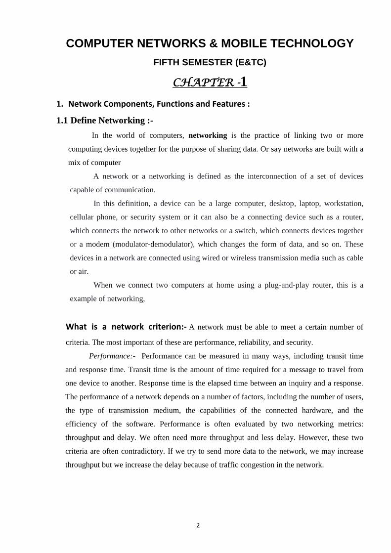
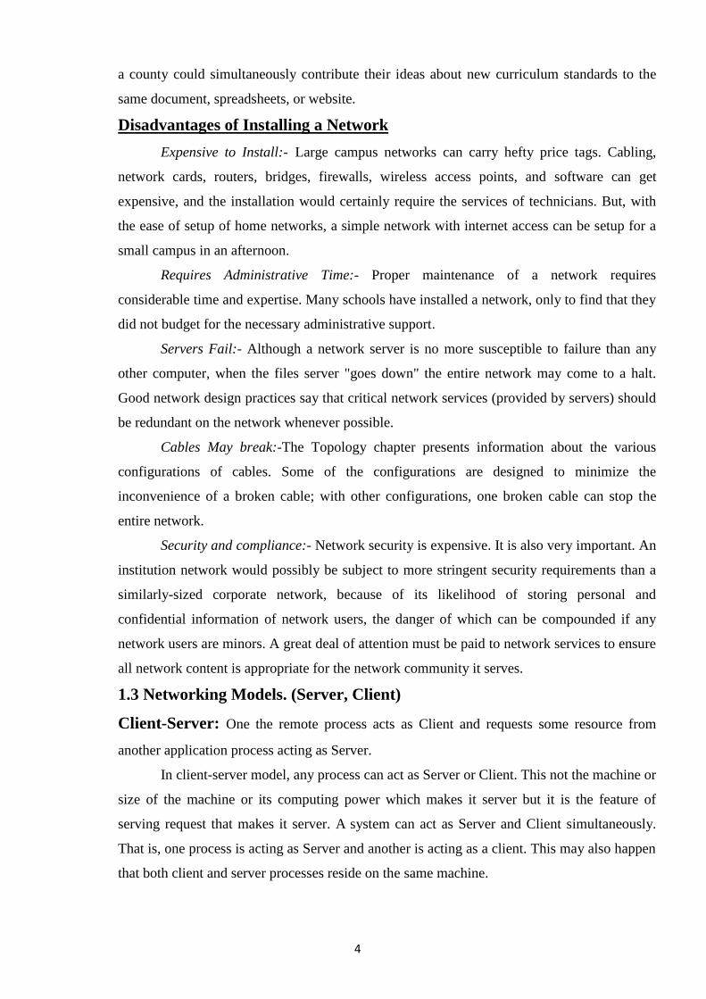
Client-Server: One the remote process acts as Client and requests some resource from
another application process acting as Server.
In client-server model, any process can act as Server or Client. This not the machine or
size of the machine or its computing power which makes it server but it is the feature of
serving request that makes it server. A system can act as Server and Client simultaneously.
That is, one process is acting as Server and another is acting as a client. This may also happen
that both client and server processes reside on the same machine.
5
Communication:-
Two processes in client-server model can interact in various ways:
1. Sockets
2. Remote Procedure Calls (RPC)
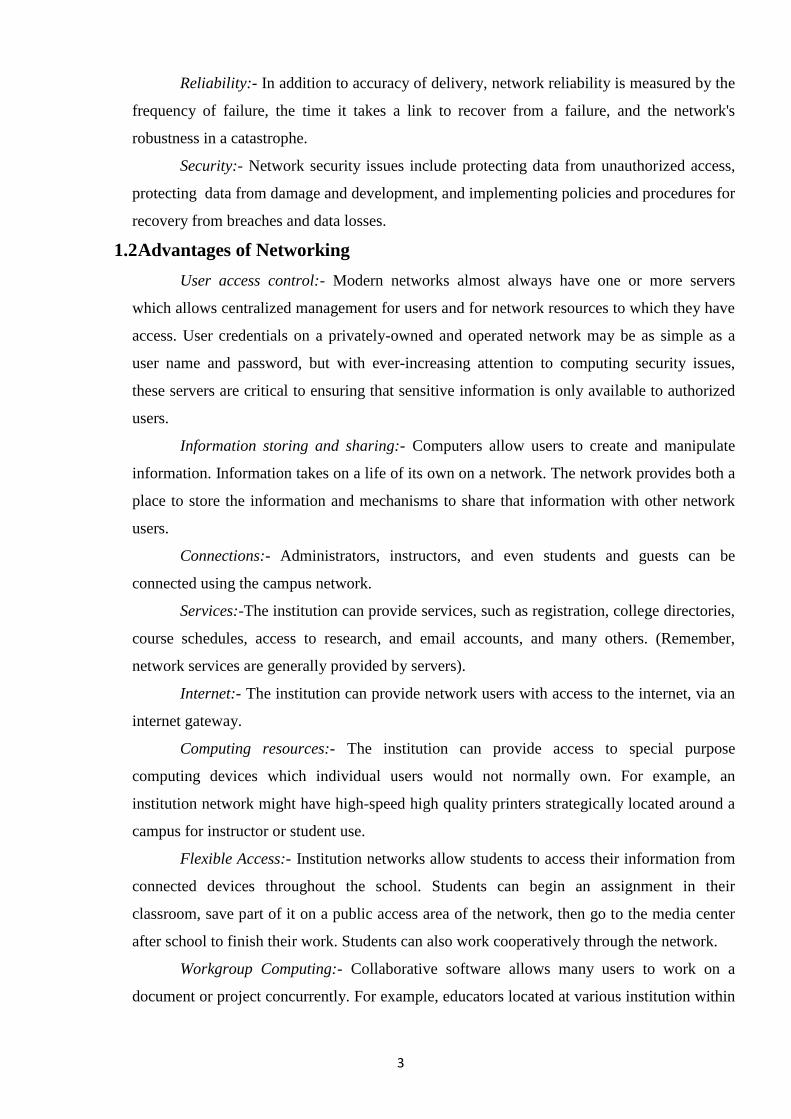
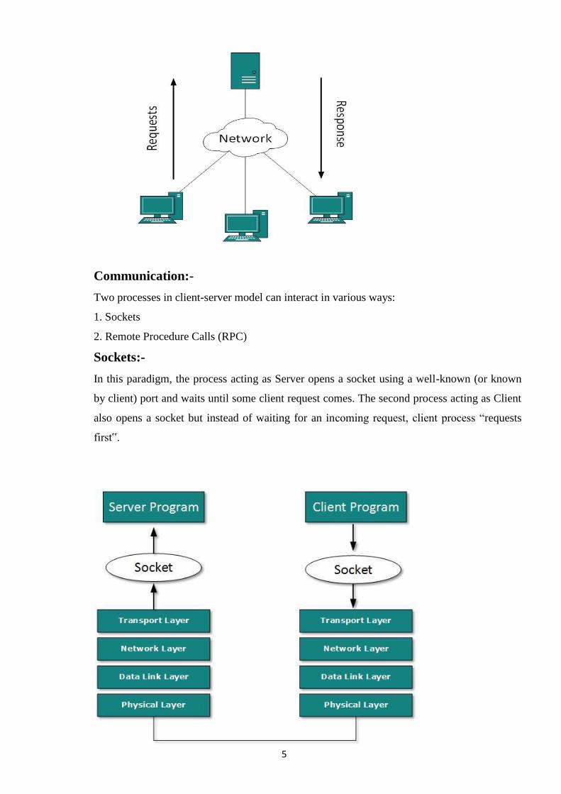
Sockets:-
In this paradigm, the process acting as Server opens a socket using a well-known (or known
by client) port and waits until some client request comes. The second process acting as Client
also opens a socket but instead of waiting for an incoming request, client process ―requests
first‟.
6
When the request is reached to server, it is served. It can either be an information sharing or
resource request.
Remote Procedure Call
This is a mechanism where one process interacts with another by means of procedure
calls. One process (client) calls the procedure lying on remote host. The process on remote
host is said to be Server. Both processes are allocated stubs. This communication happens in
the following way:
1.The client process calls the client stub. It passes all the parameters pertaining to program
local to it.
2. All parameters are then packed (marshalling) and a system call is made to send them to
other side of the network is made.
3. Kernel sends the data over the network and the other end receives it.
4. The remote host passes data to the server stub where it is un marshalled.
5. The parameters are passed to the procedure and the procedure is then executed.
6. The result is sent back to the client in the same manner.
Benefits of C/S model:-
1. Divides Application processing across multiple machines:
2. Non-critical data & functions are processed on the client.
3. Critical functions are processed on the server.
4. Optimizes client workstations for data input and presentation ( e.g. graphics & mouse
support)
5. Optimizes the server for data processing and storage (e.g. large amount of memory and disk
space)
6. Scales Horizontally-Multiple servers, each server having capabilities and processing power,
can be added to distribute processing load.
7. Scales vertically- can be moved to more powerful machines, such as minicomputer or a
mainframe to take advantages of the large system‘s performance.
8. Reduces Data Replication- Data stored on the servers instead of each client, reducing the
amount of data replication for the application.
1.4 Transmission Media
The medium over which the information between two computer systems is sent, called
Transmission Media. Transmission media comes in two forms.
7
Guided Media:- All communication wires/cables comes into this type of media, such as
UTP, Coaxial and Fiber Optics. In this media the sender and receiver are directly connected
and the information is send (guided) through it.
Unguided Media:- Wireless or open air space is said to be unguided media, because there is
no connectivity between the sender and receiver. Information is spread over the air, and
anyone including the actual recipient may collect the information.
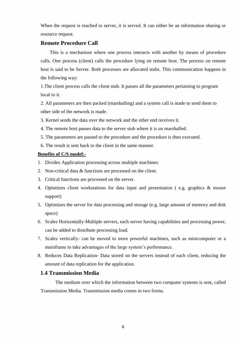
Twisted Pair Cable
A twisted pair cable is made of two plastic insulated copper wires twisted together to
form a single media. Out of these two wires only one carries actual signal and another is
used for ground reference. The twist between wires is helpful in reducing noise (electro-
magnetic interference) and crosstalk.
There are two types of twisted pair cables available:
(a) Shielded Twisted Pair (STP) Cable
(b) Unshielded Twisted Pair (UTP) Cable
STP cables comes with twisted wire pair covered in metal foil. This makes it more
indifferent to noise and crosstalk. UTP has seven categories, each suitable for specific use.
In computer networks, Cat-5, Cat-5e and Cat-6 cables are mostly used. UTP cables are
connected by RJ45 connectors.
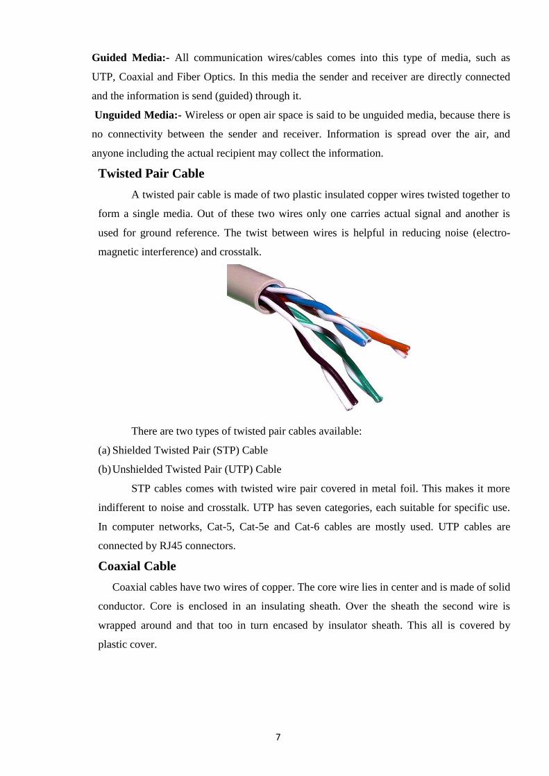
Coaxial Cable
Coaxial cables have two wires of copper. The core wire lies in center and is made of solid
conductor. Core is enclosed in an insulating sheath. Over the sheath the second wire is
wrapped around and that too in turn encased by insulator sheath. This all is covered by
plastic cover.
8
Because of its structure coax cables are capable of carrying high frequency signals
than that of twisted pair cables. The wrapped structure provides it a good shield against
noise and cross talk. Coaxial cables provide high bandwidth rates of up to 450 mbps. There
are three categories of Coax cables namely, RG-59 (Cable TV), RG-58 (Thin Ethernet) and
RG-11 (Thick Ethernet. RG stands for Radio Government. Cables are connected using BNC
connector and BNC-T. BNC terminator is used to terminate the wire at the far ends.
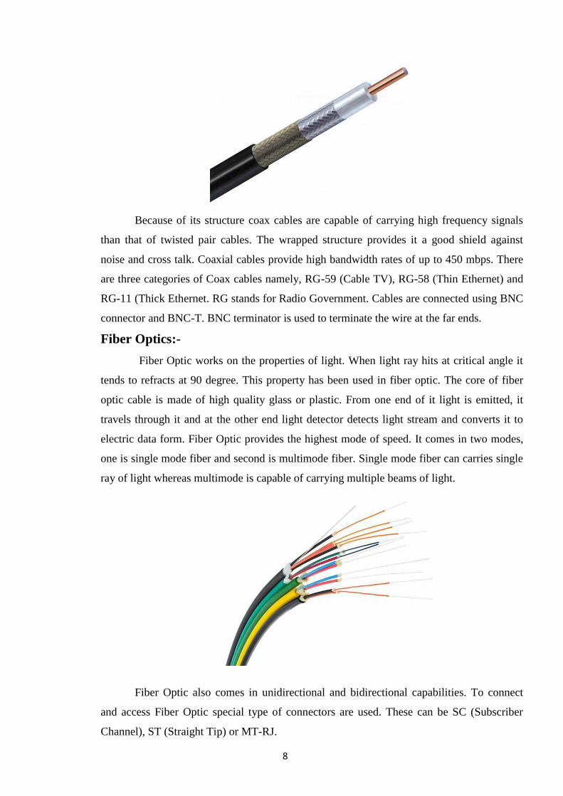
Fiber Optics:-
Fiber Optic works on the properties of light. When light ray hits at critical angle it
tends to refracts at 90 degree. This property has been used in fiber optic. The core of fiber
optic cable is made of high quality glass or plastic. From one end of it light is emitted, it
travels through it and at the other end light detector detects light stream and converts it to
electric data form. Fiber Optic provides the highest mode of speed. It comes in two modes,
one is single mode fiber and second is multimode fiber. Single mode fiber can carries single
ray of light whereas multimode is capable of carrying multiple beams of light.
Fiber Optic also comes in unidirectional and bidirectional capabilities. To connect
and access Fiber Optic special type of connectors are used. These can be SC (Subscriber
Channel), ST (Straight Tip) or MT-RJ.
9
COMPARISON BETWEEN TWISTED PAIR CABLE, CO-AXIAL CABLE AND OPTICAL FIBER
Sl no Twisted pair cable Co-axial cable Optical fiber
1 Transmission of signals
takes place in the
electrical form over the
metallic conducting
wires.
Transmission of signals
take place in the inner
conductor of the cable
Signal transmission takes place in an optical form over a glass fiber.
2 Noise immunity is low.
Therefore more
distortion
Higher noise immunity
than the twisted pair
cable due to the presence
of shielding conductor
Higher noise immunity as the light rays are unaffected by the electrical noise.
3 Affected due to external
magnetic field
Less affected due to
external magnetic field
Not affected by the external magnetic field.
4 Short circuit between the
two conductor is possible
Short circuit between the
two conductor is possible
Short circuit is not possible
5 Cheapest Moderately expensive Expensive
6 Can support low data
rates
Moderately high data rate Very high data rates.
7 Low bandwidth Moderately high
bandwidth
Very high bandwidth
8 Easy to installed Installation is fairly easy Installation is difficult
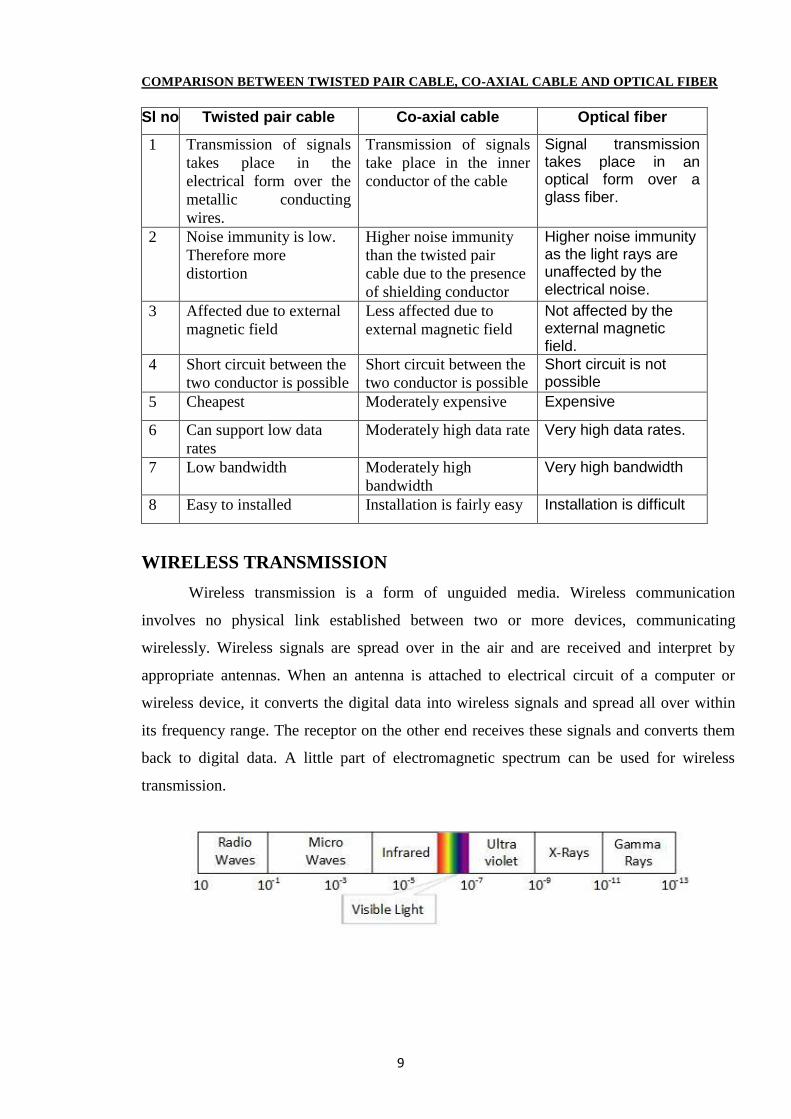
WIRELESS TRANSMISSION
Wireless transmission is a form of unguided media. Wireless communication
involves no physical link established between two or more devices, communicating
wirelessly. Wireless signals are spread over in the air and are received and interpret by
appropriate antennas. When an antenna is attached to electrical circuit of a computer or
wireless device, it converts the digital data into wireless signals and spread all over within
its frequency range. The receptor on the other end receives these signals and converts them
back to digital data. A little part of electromagnetic spectrum can be used for wireless
transmission.
10
Before understanding the different types of wireless transmission medium, let us first
understand the ways in which wireless signals travel. These signals can be sent or
propagated in the following three ways:
1. Ground-wave propagation
2. Sky-wave propagation
3. Line-of-sight propagation
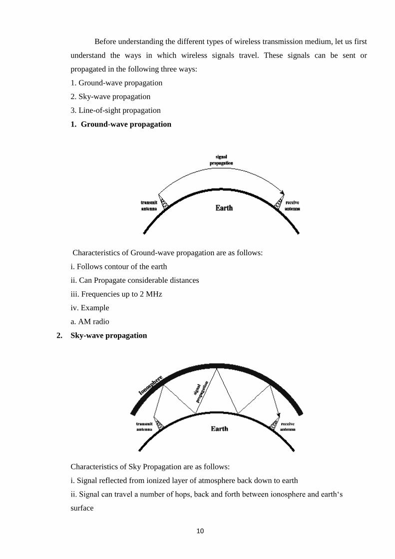
1. Ground-wave propagation
Characteristics of Ground-wave propagation are as follows:
i. Follows contour of the earth
ii. Can Propagate considerable distances
iii. Frequencies up to 2 MHz
iv. Example
a. AM radio
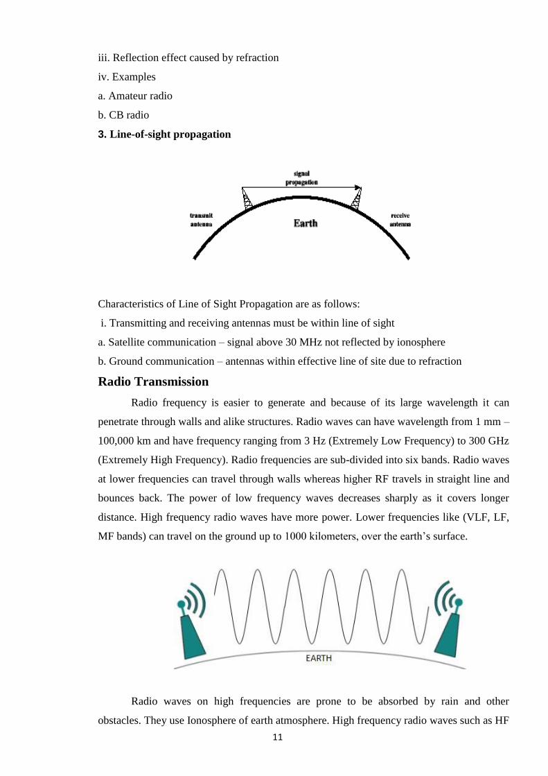
2. Sky-wave propagation
Characteristics of Sky Propagation are as follows:
i. Signal reflected from ionized layer of atmosphere back down to earth
ii. Signal can travel a number of hops, back and forth between ionosphere and earth‗s
surface
11
iii. Reflection effect caused by refraction
iv. Examples
a. Amateur radio
b. CB radio
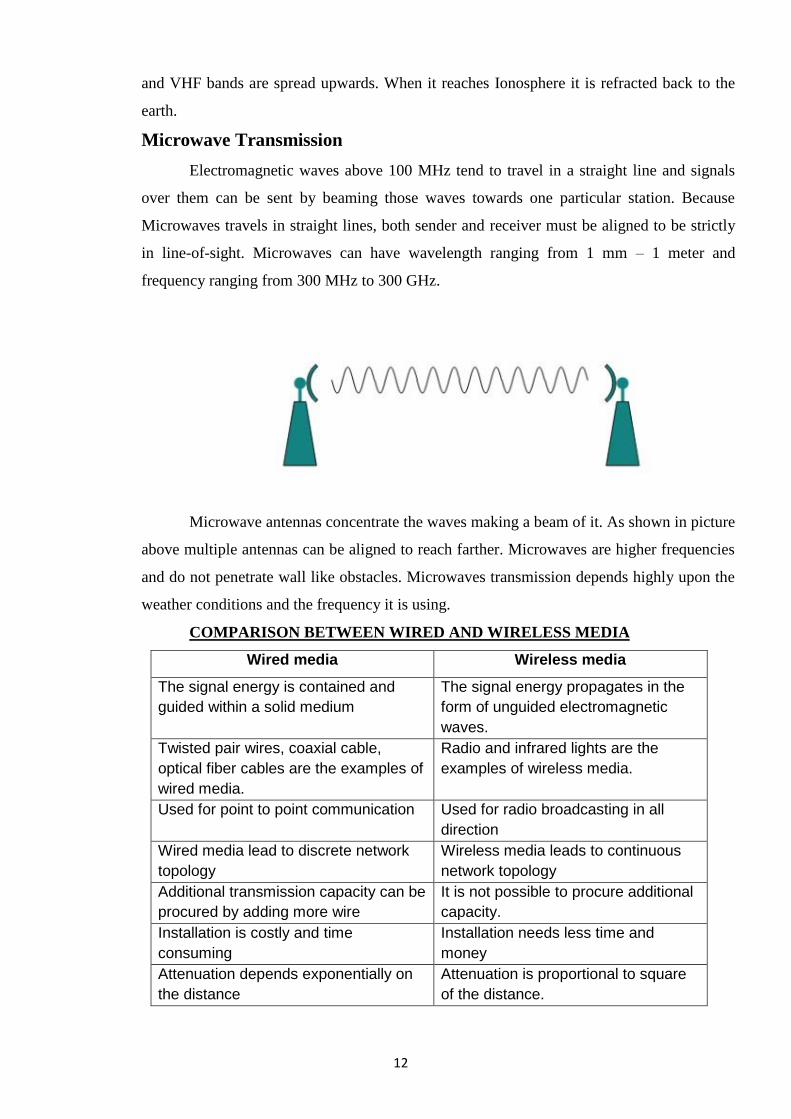
3. Line-of-sight propagation
Characteristics of Line of Sight Propagation are as follows:
i. Transmitting and receiving antennas must be within line of sight
a. Satellite communication – signal above 30 MHz not reflected by ionosphere
b. Ground communication – antennas within effective line of site due to refraction
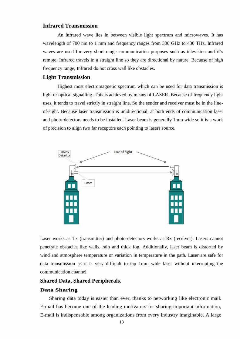
Radio Transmission
Radio frequency is easier to generate and because of its large wavelength it can
penetrate through walls and alike structures. Radio waves can have wavelength from 1 mm –
100,000 km and have frequency ranging from 3 Hz (Extremely Low Frequency) to 300 GHz
(Extremely High Frequency). Radio frequencies are sub-divided into six bands. Radio waves
at lower frequencies can travel through walls whereas higher RF travels in straight line and
bounces back. The power of low frequency waves decreases sharply as it covers longer
distance. High frequency radio waves have more power. Lower frequencies like (VLF, LF,
MF bands) can travel on the ground up to 1000 kilometers, over the earth‘s surface.
Radio waves on high frequencies are prone to be absorbed by rain and other
obstacles. They use Ionosphere of earth atmosphere. High frequency radio waves such as HF
12
and VHF bands are spread upwards. When it reaches Ionosphere it is refracted back to the
earth.
Microwave Transmission
Electromagnetic waves above 100 MHz tend to travel in a straight line and signals
over them can be sent by beaming those waves towards one particular station. Because
Microwaves travels in straight lines, both sender and receiver must be aligned to be strictly
in line-of-sight. Microwaves can have wavelength ranging from 1 mm – 1 meter and
frequency ranging from 300 MHz to 300 GHz.
Microwave antennas concentrate the waves making a beam of it. As shown in picture
above multiple antennas can be aligned to reach farther. Microwaves are higher frequencies
and do not penetrate wall like obstacles. Microwaves transmission depends highly upon the
weather conditions and the frequency it is using.
COMPARISON BETWEEN WIRED AND WIRELESS MEDIA
Wired media Wireless media
The signal energy is contained and
guided within a solid medium
The signal energy propagates in the
form of unguided electromagnetic
waves.
Twisted pair wires, coaxial cable,
optical fiber cables are the examples of
wired media.
Radio and infrared lights are the
examples of wireless media.
Used for point to point communication Used for radio broadcasting in all
direction
Wired media lead to discrete network
topology
Wireless media leads to continuous
network topology
Additional transmission capacity can be
procured by adding more wire
It is not possible to procure additional
capacity.
Installation is costly and time
consuming
Installation needs less time and
money
Attenuation depends exponentially on
the distance
Attenuation is proportional to square
of the distance.
13
Infrared Transmission
An infrared wave lies in between visible light spectrum and microwaves. It has
wavelength of 700 nm to 1 mm and frequency ranges from 300 GHz to 430 THz. Infrared
waves are used for very short range communication purposes such as television and it‘s
remote. Infrared travels in a straight line so they are directional by nature. Because of high
frequency range, Infrared do not cross wall like obstacles.
Light Transmission
Highest most electromagnetic spectrum which can be used for data transmission is
light or optical signalling. This is achieved by means of LASER. Because of frequency light
uses, it tends to travel strictly in straight line. So the sender and receiver must be in the line-
of-sight. Because laser transmission is unidirectional, at both ends of communication laser
and photo-detectors needs to be installed. Laser beam is generally 1mm wide so it is a work
of precision to align two far receptors each pointing to lasers source.
Laser works as Tx (transmitter) and photo-detectors works as Rx (receiver). Lasers cannot
penetrate obstacles like walls, rain and thick fog. Additionally, laser beam is distorted by
wind and atmosphere temperature or variation in temperature in the path. Laser are safe for
data transmission as it is very difficult to tap 1mm wide laser without interrupting the
communication channel.
Shared Data, Shared Peripherals,
Data Sharing
Sharing data today is easier than ever, thanks to networking like electronic mail.
E-mail has become one of the leading motivators for sharing important information,
E-mail is indispensable among organizations from every industry imaginable. A large
14
number of us have become used to seeing a flashing icon or some other indicator
signaling a letter waiting in our electronic mailboxes. The letter itself may contain
notes about a friendly
Transmitting E-mail is one method of sharing data, but obviously there are others. Shared
files may exist in one location with multiple people accessing them or updating parts of them.
Database applications are found in virtually every computerized organization. Networks offer
the capabilities of multi-user access. As you can imagine, there is inherent danger in two
people accessing and altering the same file at the same time. What happens if two people
update the same record at once? In times past this scenario would result in the "deadly
embrace", where both parties became locked up and had to reboot, resulting in lost or
corrupted data. More sophisticated database applications incorporate record locking; a means
by which a person updating a record has exclusive use of the record while others who attempt
to access it cannot do so. This certainly eliminates the problems surrounding lock-ups but
doesn't really eliminate the frustration of waiting on a record that someone else is updating,
especially if that someone forgot what they were doing and headed off to lunch.
Not only data files may be shared, but executable files may be shared as well When a user
invokes an executable file on a network server, a copy of it is transmitted over the network
into the memory of the local user's workstation. That is where the actual execution takes
place, not on the file server the fact that execution takes place locally is what distinguishes PC
networks from mainframe networks where processing is done centrally on the host and the
terminals merely display the result. Once the executable file has been copied, it is then
available for copying by other users. In this manner, a Single executable file on a central file
server can work for multiple users. Great care should be taken, however, to ensure that
sufficient licensure has been secured in a multi-user environment so as to remain legal.
Resource Sharing
One of the distinct benefits of modern networking is the ability to share peripherals. Few
companies have the available resources to place a printer on every user's desk. Networks offer
a logical and cost-effective solution. Since, once again, the introduction of several users could
cause conflict at the printer; spooling is utilized so that print jobs can be arranged in an
orderly manner. Network provides such services in the form of print queues and print servers.
The ability of sharing printers and disk space has been the driving force behind many
companies Installing PC-based networks. Networks are now found in nearly every type of
industry there is. From small companies to large multi-national corporations, all benefit from
sharing peripherals, including modems Shared modems are typically called modem servers
Today's incarnations support multiple lines and are feature-laden
15
Answer a network card, network adapter, network interface card or NIC is a piece of
computer hardware designed to allow computers to communicate over a computer network. It
is an OSI model layer 2 item because it has a MAC address. Every network card has a unique
48-bit serial number called a MAC address, which is written to ROM carried on the card.
Every computer on a network must have a card with a unique MAC address. The IEEE is
responsible for assigning MAC addresses to the vendors of network interface cards. No two
cards ever manufactured should share the same address. Whereas network cards used to be
expansion cards to plug into a computer bus, most newer computers have a network interface
built into the motherboard A separate network card is not required unless multiple interfaces
are needed or some other type of network is used. The card implements the electronic
circuitry required to communicate using a specific physical layer and data link layer standard
such as Ethernet or token ring. This provides a base for a full network protocol stack,
allowing communication among small groups of computers on the same LAN and large-scale
network communications through routable protocols, such as IP. There are four techniques
used for transfer of data, the NIC may use one or more of these techniques. * Polling is where
the microprocessor examines the status of the peripheral under program control. *
Programmed I/O is where the microprocessor alerts the designated peripheral by applying its
address to the system's address bus. * Interrupt-driven I/O is where the peripheral alerts the
microprocessor that it‘s ready to transfer data. * DMA is where the intelligent peripheral
assumes control of the system bus to access memory directly. This removes load from the
CPU but requires a separate processor on the card. A network card typically has a twisted
pair, BNC, or AUI socket where the network cable is connected, and a few LEDs to inform
the user of whether the network is active, and whether or not there is data being transmitted
on it. The Network Cards are typically available in 10/100/1000 Mbit/s. This means they can
support a transfer rate of 10 or 100 or 1000 Mbit/s.
1.5 Network Interface Cards (NIC)
Network Interface Card, a NIC is also commonly referred to as an Ethernet card and
network adapter and is an expansion card that enables a computer to connect to a network
such as a home network or the Internet using an Ethernet cable with a RJ-45 connector. The
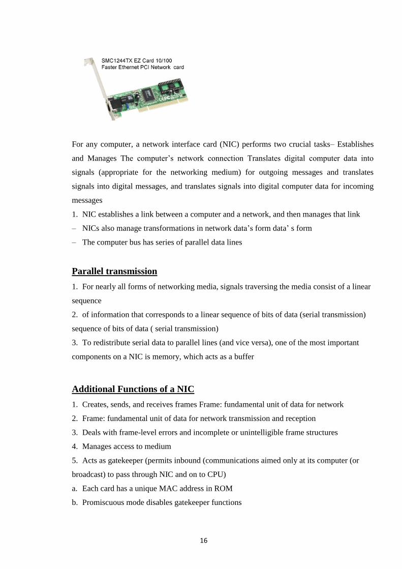
picture is an example of a SMC EZ Card 10/100 PCI network card, a network card commonly
found in most desktop computers today that do not already have an onboard network on their
motherboard.
16
For any computer, a network interface card (NIC) performs two crucial tasks– Establishes
and Manages The computer‘s network connection Translates digital computer data into
signals (appropriate for the networking medium) for outgoing messages and translates
signals into digital messages, and translates signals into digital computer data for incoming
messages
1. NIC establishes a link between a computer and a network, and then manages that link
– NICs also manage transformations in network data‘s form data‘ s form
– The computer bus has series of parallel data lines
Parallel transmission
1. For nearly all forms of networking media, signals traversing the media consist of a linear
sequence
2. of information that corresponds to a linear sequence of bits of data (serial transmission)
sequence of bits of data ( serial transmission)
3. To redistribute serial data to parallel lines (and vice versa), one of the most important
components on a NIC is memory, which acts as a buffer
Additional Functions of a NIC
1. Creates, sends, and receives frames Frame: fundamental unit of data for network
2. Frame: fundamental unit of data for network transmission and reception
3. Deals with frame-level errors and incomplete or unintelligible frame structures
4. Manages access to medium
5. Acts as gatekeeper (permits inbound (communications aimed only at its computer (or
broadcast) to pass through NIC and on to CPU)
a. Each card has a unique MAC address in ROM
b. Promiscuous mode disables gatekeeper functions
17
1.7 Network Operating Systems
In order to transmit signals across a network, it is necessary for the computer to
communicate with its modem or Network Interface Card. Network Operating Systems (NOS)
provide the protocols necessary to achieve this goal, but each different type of modem or NIC
needs to be able to communicate with the particular NOS. It is therefore necessary to install the
special software that comes with the interface device. This software is often referred to as a
driver. Computers made today usually come with both the interface and necessary drivers
installed. Occasionally, you must install the modem or NIC yourself. It is necessary to install
the correct driver for that interface device. Failure to so install the driver means that the device
will be unable to communicate over the network or with the computer it is installed in.
Network Operating Systems not only allow communication across a network, they also
allow a network administrator to organize resources, control access, and ensure that the
network is operating efficiently. Sharing of network resources can be peer-to-peer or
client/server. Which one is the best is dependent on the end goal of the network.
Sharing of network resources can be peer-to-peer or client/server. Which one is the best
is dependent on the end goal of the network.
In peer-to-peer networking there is a complete sharing of resources, both hardware and
software. All systems act as both users of resources and providers of resources, but no one
system is dedicated to a single function. Peer-to-peer networks are generally best suited to
small networks and usually are less expensive than client/server networks. Client/server
networks dictate that systems are most often dedicated to a single function. They are either
users of network resources or providers of resources. Client/server networks are typically more
expensive and robust than peer-to-peer networks and generally support the building of larger
networks. The four major systems currently in use: Windows, Novell, UNIX/LINUX, and Mac.
18
CHAPTER -2
Network Topology & Classification
NETWORK TOPOLOGY
What is Topology:- A topology is a description of the layout of a specific region or area. A
network topology is a description of the layout of the region or area covered by that network.
There are two types of connections that describe how many devices connect to a single cable
or segment of transmission media. They are: point-to-point and multi-point. Point-to-point
connections provide a direct link between two devices; for example, a computer connected
directly to a printer, or a modem to a mainframe. Multi-point connections provide a link
between three or more devices on a network. All computer networks rely upon point-to-
point and multi-point connections.
The Technical Concept of Topology
The virtual shape or structure of a network is referred as topology. The pattern or layout
of interconnections of different elements or nodes of a computer network is a network topology
that might be logical or physical. However, the complete physical structure of the cable (or
transmission media) is called the physical topology. The physical topology of a network refers to
the configuration of cables, computers, and other peripherals. The way data flows through the
network (or transmission media) is called the logical topology. A logical topology is the method
used to pass information between workstations.
Types of Topology?
There are seven basic topologies in the study of network topology:
1. Point-to-point topology,
2. Bus (point-to-multipoint) topology,
3. Ring topology,
4. Star topology,
5. Hybrid topology,
6. Mesh topology and
7. Tree topology.
The interconnections between computers whether logical or physical are the foundation
of this classification. Logical topology is the way a computer in a given network transmits
information, not the way it looks or connected, along with the varying speeds of cables used
from one network to another.
19
On the other hand the physical topology is affected by a number of factors:
1. Troubleshooting technique,
2. Installation cost,
3. Office layout and
4. Cables‗ types.
The physical topology is figured out on the basis of a network‗s capability to access
media and devices, the fault tolerance desired and the cost of telecommunications circuits.
The classification of networks by the virtue of their physical span is as follows: Local
Area Networks (LAN), Wide Area Internetworks (WAN) and Metropolitan Area Networks or
campus or building internetworks.
Topology Classification
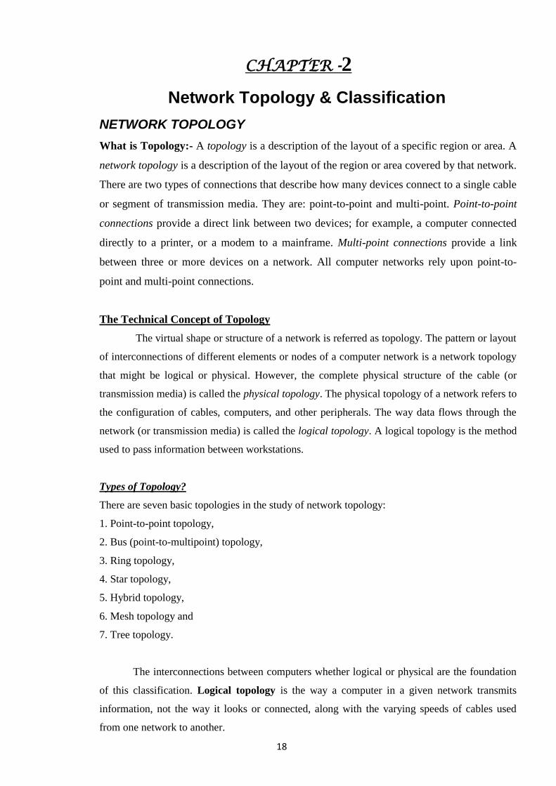
Point-to-Point Network Topology
It is the basic model of typical telephony. The simplest topology is a permanent
connection between two points. The value of a demanding point-to-point network is
proportionate to the number of subscribers‗ potential pairs. It is possible to establish a permanent
circuit within many switched
Telecommunication systems: the telephone present in a lobby would always connect to
the same port, no matter what number is being dialed. A switch connection would save the cost
between two points where the resources could be released when no longer required.
Bus Network Topology
LANs that make use of bus topology connects each node to a single cable. Some
connector connects each computer or server to the bus cable. For avoiding the bouncing of
signal a terminator is used at each end of the bus cable. The source transmits a signal that travels
in both directions and passes all machines unless it finds the system with IP address, the
intended recipient. The data is ignored in case the address is unmatched. The installation of one
cable makes bus topology an inexpensive solution as compared to other topologies; however the
maintenance cost is high. If the cable is broken all systems would collapse.
o Linear Bus: If all network nodes are connected to a combine transmission medium that has
two endpoints the Bus is Linear. The data transmitted between these nodes is transmitted over
the combine medium and received by all nodes simultaneously.
20
Distributed Bus: If all network nodes are connected to a combine transmission medium that
has more than two endpoints created by branching the main section of the transmitting medium.
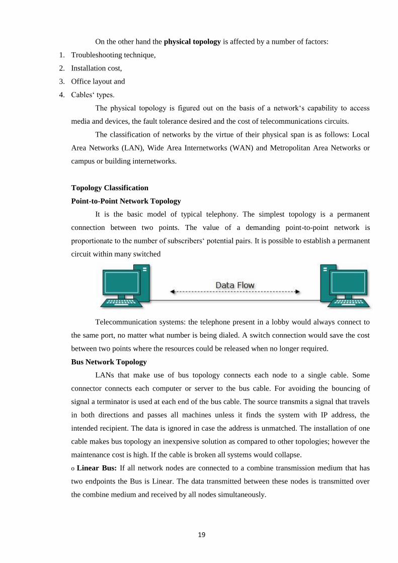
A linear bus topology consists of a main run of cable with a terminator at each end. All
nodes (file server, workstations, and peripherals) are connected to the linear cable. A bus
topology uses one long cable (backbone) to which network devices are either directly attached or
are attached by using short drop cables. Because all workstations share this bus, a workstation
checks for any information that might be coming down the backbone before sending their
messages. All messages pass the other workstations on the way to their destinations. Each
workstation then checks the address of each message to see if it matches its own. Note that bus
network topologies, the backbone must be terminated at both ends to remove the signal from the
wire after it has passed all devices on the network.
Advantages of a Linear Bus Topology
1. Easy to connect a computer or peripheral to a linear bus.
2. Requires less cable length than a star topology.
Disadvantages of a Linear Bus Topology
1. Entire network shuts down if there is a break in the main cable.
2. Terminators are required at both ends of the backbone cable.
3. Difficult to identify the problem if the entire network shuts down.
4. Not meant to be used as a stand-alone solution in a large building.
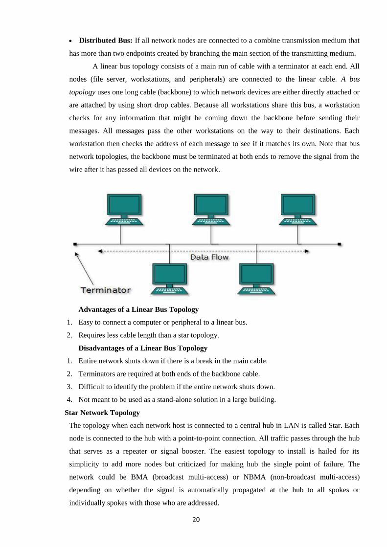
Star Network Topology
The topology when each network host is connected to a central hub in LAN is called Star. Each
node is connected to the hub with a point-to-point connection. All traffic passes through the hub
that serves as a repeater or signal booster. The easiest topology to install is hailed for its
simplicity to add more nodes but criticized for making hub the single point of failure. The
network could be BMA (broadcast multi-access) or NBMA (non-broadcast multi-access)
depending on whether the signal is automatically propagated at the hub to all spokes or
individually spokes with those who are addressed.
21
o Extended Star: A network that keeps one or more than one repeaters between the central node
or hub and the peripheral or the spoke node, supported by the transmitter power of the hub and
beyond that supported by the standard of the physical layer of the network.
o Distributed Star: The topology is based on the linear connectivity that is Daisy Chained with
no top or centre level connection points.
Advantages of a Star Topology
1. Easy to install and wire.
2. No disruptions to the network when connecting or removing devices.
3. Easy to detect faults and to remove parts.
Disadvantages of Star Topology
1. Requires more cable length than a linear topology.
2. If the hub, switch, or concentrator fails, nodes attached are disabled.
3. More expensive than linear bus topologies because of the cost of the hubs, etc.
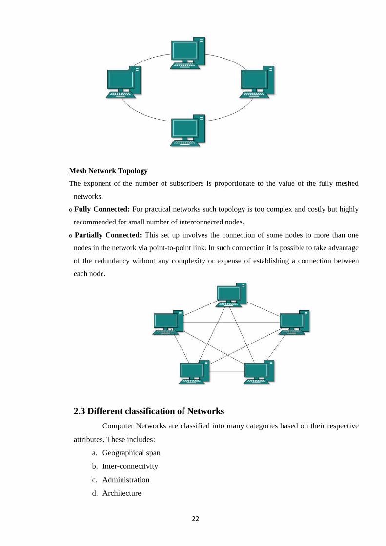
Ring Network Topology
Ring topology is one of the old ways of building computer network design and it is
pretty much obsolete. FDDI, SONET or Token Ring technologies are used to build ring
technology. It is not widely popular in terms of usability but in case if you find it anywhere it
will mostly be in schools or office buildings. Such physical setting sets up nodes in a circular
manner where the data could travel in one direction where each device on the right serves as a
repeater to strengthen the signal as it moves ahead.
22
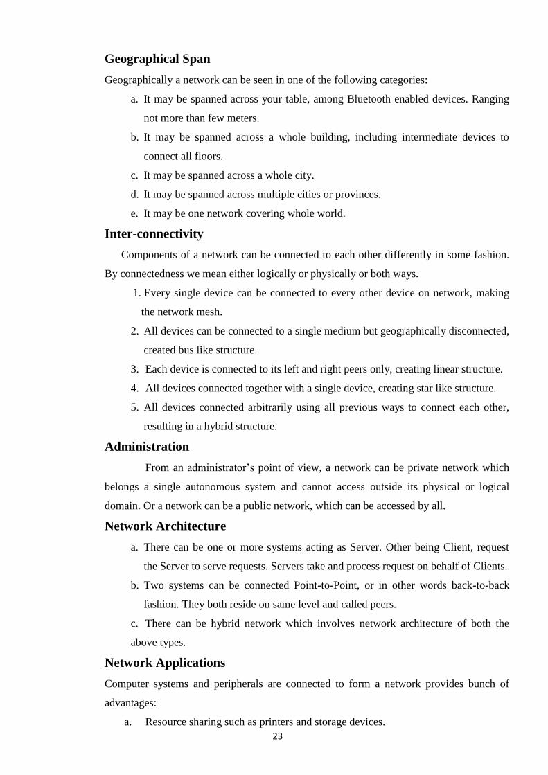
Mesh Network Topology
The exponent of the number of subscribers is proportionate to the value of the fully meshed
networks.
o Fully Connected: For practical networks such topology is too complex and costly but highly
recommended for small number of interconnected nodes.
o Partially Connected: This set up involves the connection of some nodes to more than one
nodes in the network via point-to-point link. In such connection it is possible to take advantage
of the redundancy without any complexity or expense of establishing a connection between
each node.
2.3 Different classification of Networks
Computer Networks are classified into many categories based on their respective
attributes. These includes:
a. Geographical span
b. Inter-connectivity
c. Administration
d. Architecture
23
Geographical Span
Geographically a network can be seen in one of the following categories:
a. It may be spanned across your table, among Bluetooth enabled devices. Ranging
not more than few meters.
b. It may be spanned across a whole building, including intermediate devices to
connect all floors.
c. It may be spanned across a whole city.
d. It may be spanned across multiple cities or provinces.
e. It may be one network covering whole world.
Inter-connectivity
Components of a network can be connected to each other differently in some fashion.
By connectedness we mean either logically or physically or both ways.
1. Every single device can be connected to every other device on network, making
the network mesh.
2. All devices can be connected to a single medium but geographically disconnected,
created bus like structure.
3. Each device is connected to its left and right peers only, creating linear structure.
4. All devices connected together with a single device, creating star like structure.
5. All devices connected arbitrarily using all previous ways to connect each other,
resulting in a hybrid structure.
Administration
From an administrator‘s point of view, a network can be private network which
belongs a single autonomous system and cannot access outside its physical or logical
domain. Or a network can be a public network, which can be accessed by all.
Network Architecture
a. There can be one or more systems acting as Server. Other being Client, request
the Server to serve requests. Servers take and process request on behalf of Clients.
b. Two systems can be connected Point-to-Point, or in other words back-to-back
fashion. They both reside on same level and called peers.
c. There can be hybrid network which involves network architecture of both the
above types.
Network Applications
Computer systems and peripherals are connected to form a network provides bunch of
advantages:
a. Resource sharing such as printers and storage devices.
24
b. Exchange of Information by means of emails and FTP.
c. Information sharing by using Web or Internet.
d. Interaction with other users using dynamic web pages.
e. IP phones
f. Video Conferences
g. Parallel computing
h. Instant Messaging
2.4 Different Networks model
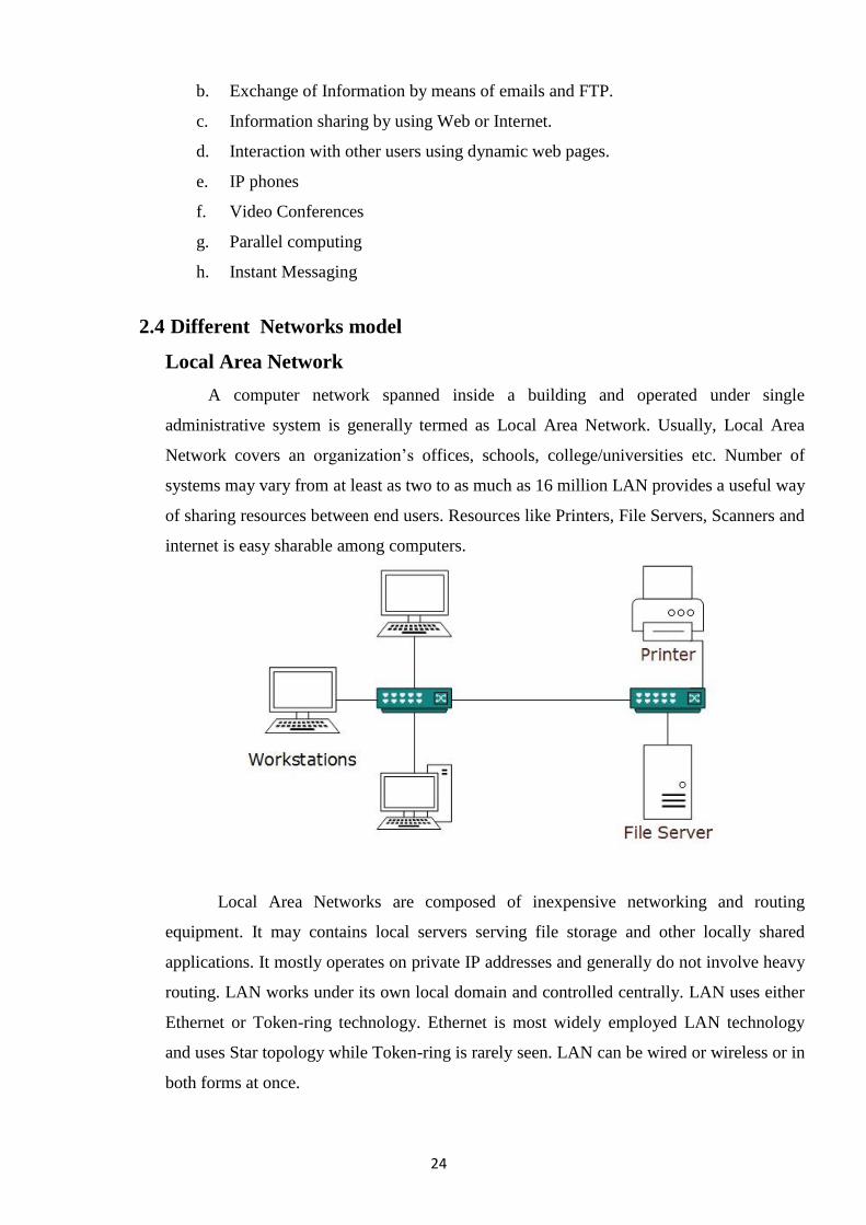
Local Area Network
A computer network spanned inside a building and operated under single
administrative system is generally termed as Local Area Network. Usually, Local Area
Network covers an organization‘s offices, schools, college/universities etc. Number of
systems may vary from at least as two to as much as 16 million LAN provides a useful way
of sharing resources between end users. Resources like Printers, File Servers, Scanners and
internet is easy sharable among computers.
Local Area Networks are composed of inexpensive networking and routing
equipment. It may contains local servers serving file storage and other locally shared
applications. It mostly operates on private IP addresses and generally do not involve heavy
routing. LAN works under its own local domain and controlled centrally. LAN uses either
Ethernet or Token-ring technology. Ethernet is most widely employed LAN technology
and uses Star topology while Token-ring is rarely seen. LAN can be wired or wireless or in
both forms at once.
25
Metropolitan Area Network
MAN, generally expands throughout a city such as cable TV network. It can be in
form of Ethernet, Token-ring, ATM or FDDI. Metro Ethernet is a service which is
provided by ISPs. This service enables its users to expand their Local Area Networks.
For example, MAN can help an organization to connect all of its offices in a City.
Backbone of MAN is high-capacity and high-speed fiber optics. MAN is works in between
Local Area Network and Wide Area Network. MAN provides uplink for LANs to WANs
or Internet.
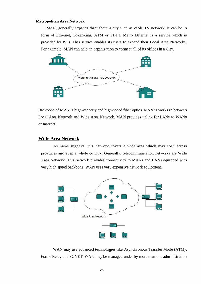
Wide Area Network
As name suggests, this network covers a wide area which may span across
provinces and even a whole country. Generally, telecommunication networks are Wide
Area Network. This network provides connectivity to MANs and LANs equipped with
very high speed backbone, WAN uses very expensive network equipment.
WAN may use advanced technologies like Asynchronous Transfer Mode (ATM),
Frame Relay and SONET. WAN may be managed under by more than one administration
26
Comparing types of network coverage
The table below compares the three types of networks:
LAN MAN WAN
Relatively small. Can incorporate
multiple LANs.
Uses data transmission
Contained within a
single building or
campus.
Contained within a
single city or
metropolitan area.
Networks to incorporate
LANs and MANs.
Generally inexpensive to
implement and maintain.
Expensive to implement
and maintain.
Essentially unlimited
geographic area.
Typically owned
privately.
Typically owned by
private providers.
Cost varies widely,
depending on how it is
configured.
2.5 Interconnection of Network
We will discuss some simple and popularly used interconnection networks
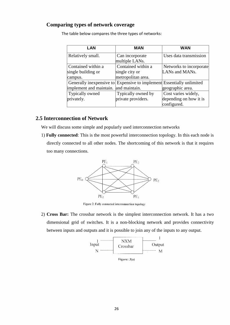
1) Fully connected: This is the most powerful interconnection topology. In this each node is
directly connected to all other nodes. The shortcoming of this network is that it requires
too many connections.
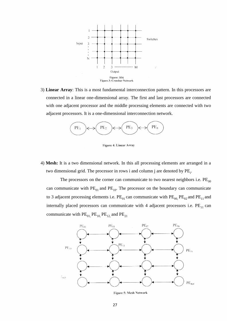
2) Cross Bar: The crossbar network is the simplest interconnection network. It has a two
dimensional grid of switches. It is a non-blocking network and provides connectivity
between inputs and outputs and it is possible to join any of the inputs to any output.
27
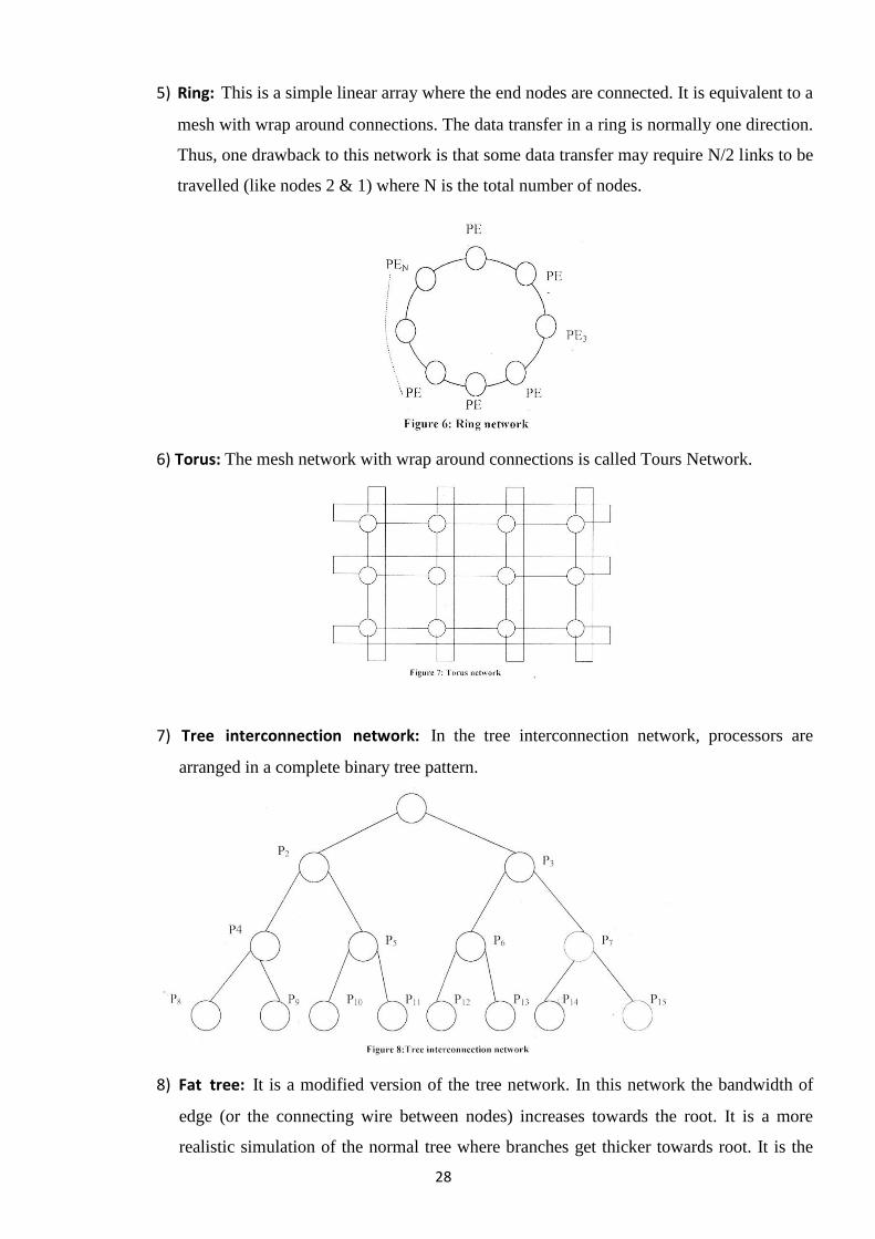
3) Linear Array: This is a most fundamental interconnection pattern. In this processors are
connected in a linear one-dimensional array. The first and last processors are connected
with one adjacent processor and the middle processing elements are connected with two
adjacent processors. It is a one-dimensional interconnection network.
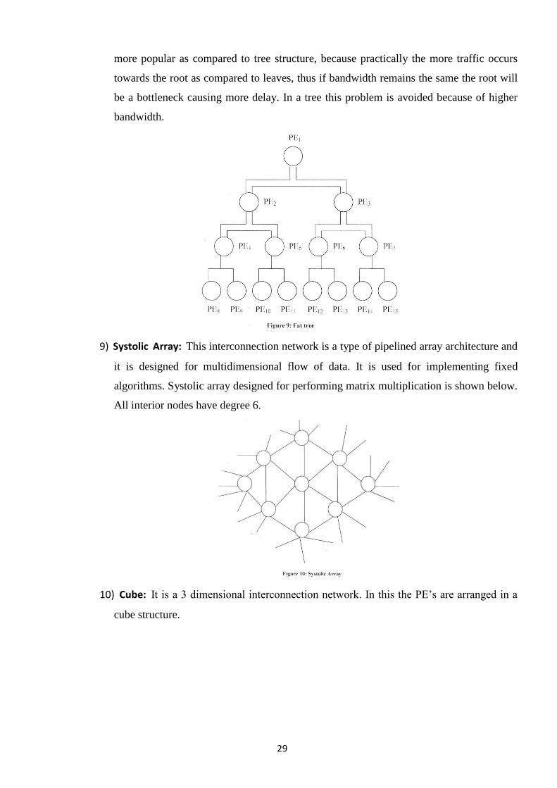
4) Mesh: It is a two dimensional network. In this all processing elements are arranged in a
two dimensional grid. The processor in rows i and column j are denoted by PEi.
The processors on the corner can communicate to two nearest neighbors i.e. PE00
can communicate with PE01 and PE10. The processor on the boundary can communicate
to 3 adjacent processing elements i.e. PE01 can communicate with PE00, PE02 and PE11 and
internally placed processors can communicate with 4 adjacent processors i.e. PE11 can
communicate with PE01, PE10, PE12, and PE21
28
5) Ring: This is a simple linear array where the end nodes are connected. It is equivalent to a
mesh with wrap around connections. The data transfer in a ring is normally one direction.
Thus, one drawback to this network is that some data transfer may require N/2 links to be
travelled (like nodes 2 & 1) where N is the total number of nodes.
6) Torus: The mesh network with wrap around connections is called Tours Network.
7) Tree interconnection network: In the tree interconnection network, processors are
arranged in a complete binary tree pattern.
8) Fat tree: It is a modified version of the tree network. In this network the bandwidth of
edge (or the connecting wire between nodes) increases towards the root. It is a more
realistic simulation of the normal tree where branches get thicker towards root. It is the
29
more popular as compared to tree structure, because practically the more traffic occurs
towards the root as compared to leaves, thus if bandwidth remains the same the root will
be a bottleneck causing more delay. In a tree this problem is avoided because of higher
bandwidth.
9) Systolic Array: This interconnection network is a type of pipelined array architecture and
it is designed for multidimensional flow of data. It is used for implementing fixed
algorithms. Systolic array designed for performing matrix multiplication is shown below.
All interior nodes have degree 6.
10) Cube: It is a 3 dimensional interconnection network. In this the PE‘s are arranged in a
cube structure.
30
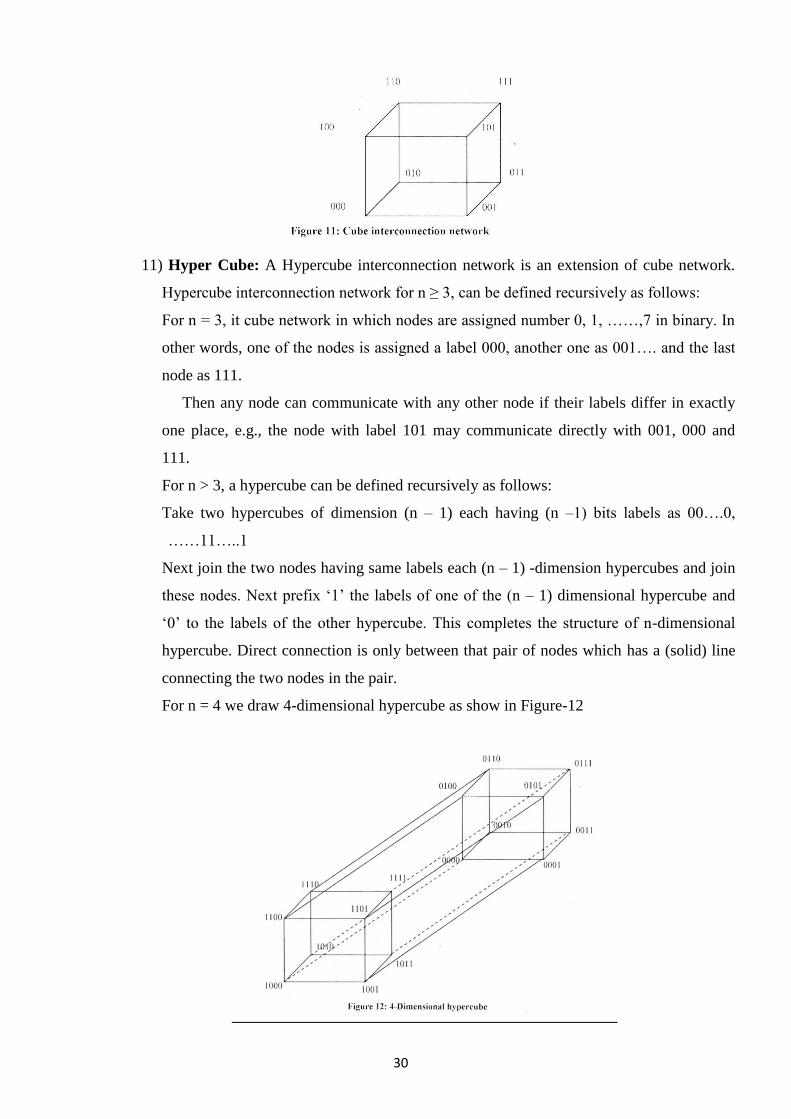
11) Hyper Cube: A Hypercube interconnection network is an extension of cube network.
Hypercube interconnection network for n ≥ 3, can be defined recursively as follows:
For n = 3, it cube network in which nodes are assigned number 0, 1, ……,7 in binary. In
other words, one of the nodes is assigned a label 000, another one as 001…. and the last
node as 111.
Then any node can communicate with any other node if their labels differ in exactly
one place, e.g., the node with label 101 may communicate directly with 001, 000 and
111.
For n > 3, a hypercube can be defined recursively as follows:
Take two hypercubes of dimension (n – 1) each having (n –1) bits labels as 00….0,
……11…..1
Next join the two nodes having same labels each (n – 1) -dimension hypercubes and join
these nodes. Next prefix ‗1‘ the labels of one of the (n – 1) dimensional hypercube and
‗0‘ to the labels of the other hypercube. This completes the structure of n-dimensional
hypercube. Direct connection is only between that pair of nodes which has a (solid) line
connecting the two nodes in the pair.
For n = 4 we draw 4-dimensional hypercube as show in Figure-12
31
CHAPTER -3
Data Communication Circuits
3.1 Different Data Communication Circuit
1. Data is transmitted between two digital devices on the network in the form of bits.
2. Transmission mode refers to the mode used for transmitting the data. The
transmission medium may be capable of sending only a single bit in unit time or
multiple bits in unit time.
3. When a single bit is transmitted in unit time the transmission mode used is Serial
Transmission and when multiple bits are sent in unit time the transmission mode
used is called Parallel transmission.
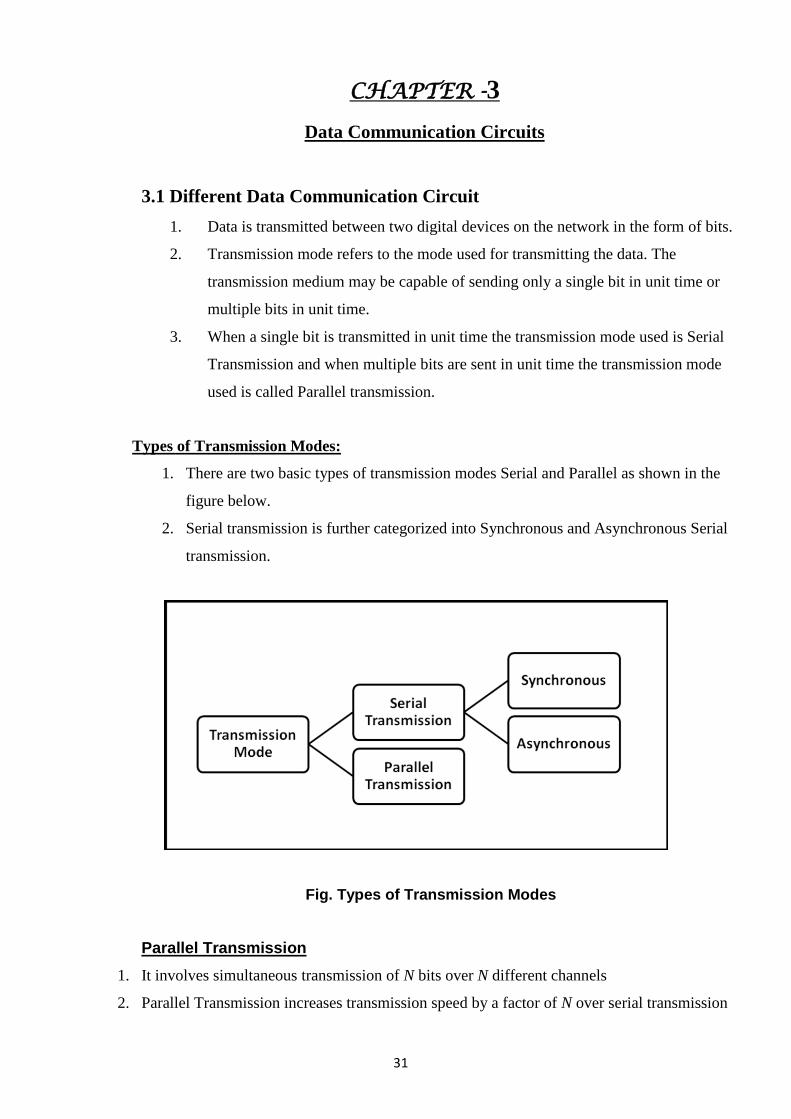
Types of Transmission Modes:
1. There are two basic types of transmission modes Serial and Parallel as shown in the
figure below.
2. Serial transmission is further categorized into Synchronous and Asynchronous Serial
transmission.
Fig. Types of Transmission Modes
Parallel Transmission
1. It involves simultaneous transmission of N bits over N different channels
2. Parallel Transmission increases transmission speed by a factor of N over serial transmission
32
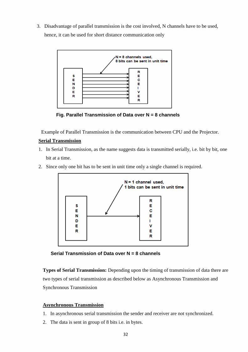
3. Disadvantage of parallel transmission is the cost involved, N channels have to be used,
hence, it can be used for short distance communication only
Fig. Parallel Transmission of Data over N = 8 channels
Example of Parallel Transmission is the communication between CPU and the Projector.
Serial Transmission
1. In Serial Transmission, as the name suggests data is transmitted serially, i.e. bit by bit, one
bit at a time.
2. Since only one bit has to be sent in unit time only a single channel is required.
Serial Transmission of Data over N = 8 channels
Types of Serial Transmission: Depending upon the timing of transmission of data there are
two types of serial transmission as described below as Asynchronous Transmission and
Synchronous Transmission
Asynchronous Transmission
1. In asynchronous serial transmission the sender and receiver are not synchronized.
2. The data is sent in group of 8 bits i.e. in bytes.
33
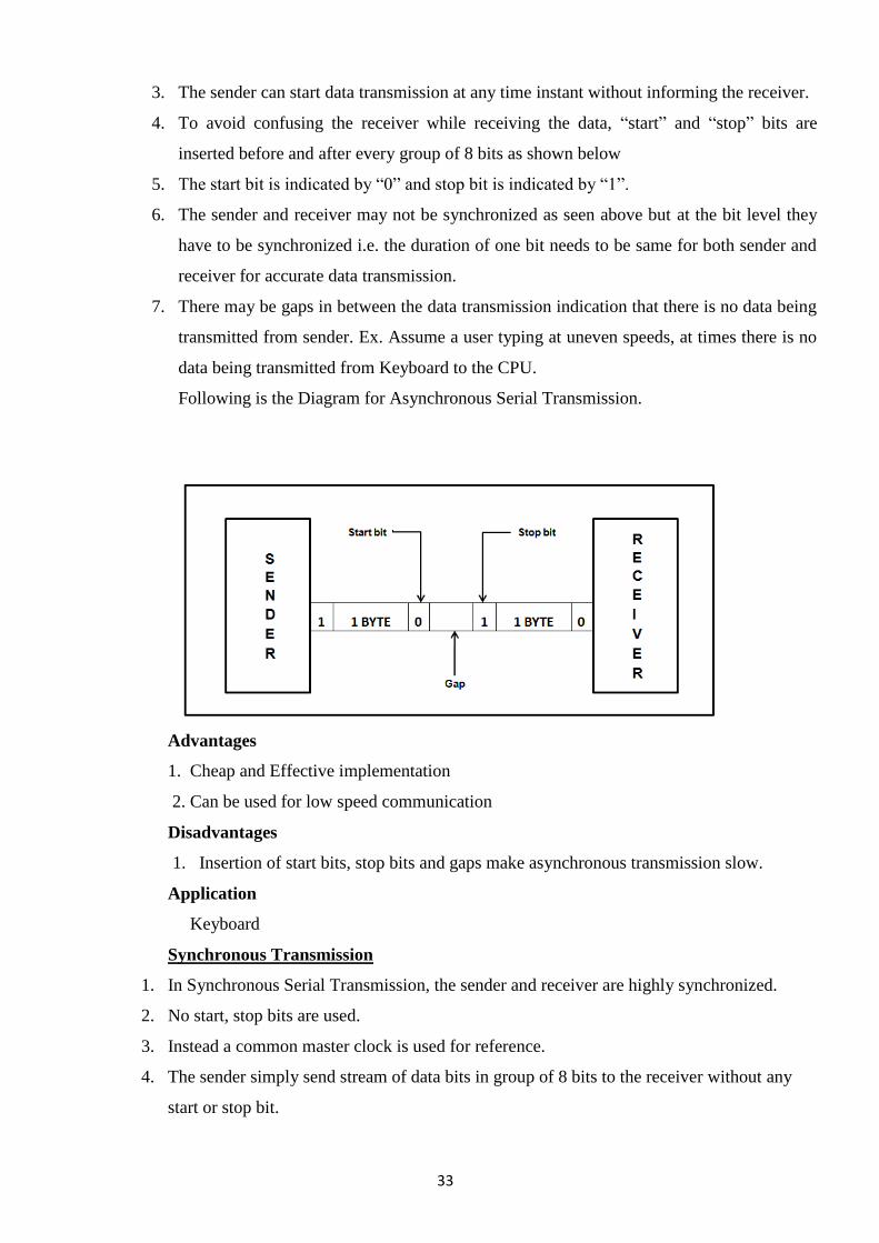
3. The sender can start data transmission at any time instant without informing the receiver.
4. To avoid confusing the receiver while receiving the data, ―start‖ and ―stop‖ bits are
inserted before and after every group of 8 bits as shown below
5. The start bit is indicated by ―0‖ and stop bit is indicated by ―1‖.
6. The sender and receiver may not be synchronized as seen above but at the bit level they
have to be synchronized i.e. the duration of one bit needs to be same for both sender and
receiver for accurate data transmission.
7. There may be gaps in between the data transmission indication that there is no data being
transmitted from sender. Ex. Assume a user typing at uneven speeds, at times there is no
data being transmitted from Keyboard to the CPU.
Following is the Diagram for Asynchronous Serial Transmission.
Advantages
1. Cheap and Effective implementation
2. Can be used for low speed communication
Disadvantages
1. Insertion of start bits, stop bits and gaps make asynchronous transmission slow.
Application
Keyboard
Synchronous Transmission
1. In Synchronous Serial Transmission, the sender and receiver are highly synchronized.
2. No start, stop bits are used.
3. Instead a common master clock is used for reference.
4. The sender simply send stream of data bits in group of 8 bits to the receiver without any
start or stop bit.
34
5. It is the responsibility of the receiver to regroup the bits into units of 8 bits once they are
received.
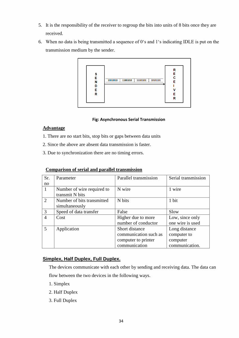
6. When no data is being transmitted a sequence of 0‗s and 1‗s indicating IDLE is put on the
transmission medium by the sender.
Fig: Asynchronous Serial Transmission
Advantage
1. There are no start bits, stop bits or gaps between data units
2. Since the above are absent data transmission is faster.
3. Due to synchronization there are no timing errors.
Comparison of serial and parallel transmission
Sr.
no
Parameter Parallel transmission Serial transmission
1 Number of wire required to
transmit N bits
N wire 1 wire
2 Number of bits transmitted
simultaneously
N bits 1 bit
3 Speed of data transfer False Slow
4 Cost Higher due to more
number of conductor
Low, since only
one wire is used
5 Application Short distance
communication such as
computer to printer
communication
Long distance
computer to
computer
communication.
Simplex, Half Duplex, Full Duplex.
The devices communicate with each other by sending and receiving data. The data can
flow between the two devices in the following ways.
1. Simplex
2. Half Duplex
3. Full Duplex
35
1. Simplex
1. In Simplex, communication is unidirectional
2. Only one of the devices sends the data and the other one only receives the data.
3. In the diagram: a CPU sends data while a monitor only receives data.
4. The simplex mode can use the entire capacity of the channel to send data in one
direction.
Example: Keyboards and traditional monitors
2. Half Duplex
1. In half duplex both the stations can transmit as well as receive but not at the same
time.
2. When one device is sending other can only receive and vice-versa (as shown in
figure )
3. The half-duplex mode is used in cases where there is no need for communication
in both directions at the same time.
4. The entire capacity of the channel can be utilized for each direction.
Example: A walkie-talkie.
3. Full Duplex
1. In Full duplex mode, both stations can transmit and receive at the same time.
2. The full-duplex mode is used when communication in both directions is required
all the time. The capacity of the channel, however, must be divided between the
two directions.
Example: One common example of full-duplex communication is the telephone
network. When two people are communicating by a telephone line, both can talk and
listen at the same time.
36
CHAPTER -4
Switching
4.1 Define Switching
Switching is the generic method for establishing a path for point-to-point
communication in a network. It involves the nodes in the network utilizing their direct
communication lines to other nodes so that a path is established in a piecewise fashion.
Each node has the capability to ‗switch‘ to a neighbouring node (i.e., a node to which it is
directly connected) to further stretch the path until it is completed. One of the most
important functions of the network layer is to employ the switching capability of the nodes
in order to route messages across the network.
There are two basic methods of switching
1. Circuit switching
2. Packet switching.
Circuit Switching
When two nodes communicate with each other over a dedicated communication
path, it is called circuit switching. There is a need of pre-specified route from which data
will travel and no other data will permitted. In simple words, in circuit switching, to
transfer data circuit must established so that the data transfer can take place. Circuits can
be permanent or temporary. Applications which use circuit switching may have to go
through three phases:
1. Establish a circuit :-
To establish an end-to-end connection before any transfer of data.
2. Transfer of data :-
Transfer data is from the source to the destination.
The data may be analog or digital, depending on the nature of the network.
The connection is generally full-duplex.
3. Disconnect the circuit :-
Terminate connection at the end of data transfer.
37
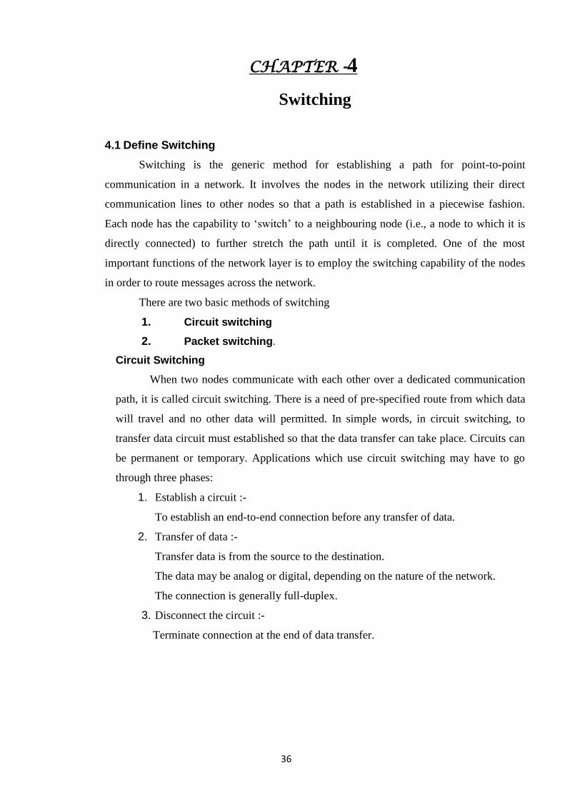
Circuit switching was designed for voice applications. Telephone is the best
suitable example of circuit switching. Before a user can make a call, a virtual path
between caller and callee is established over the network.
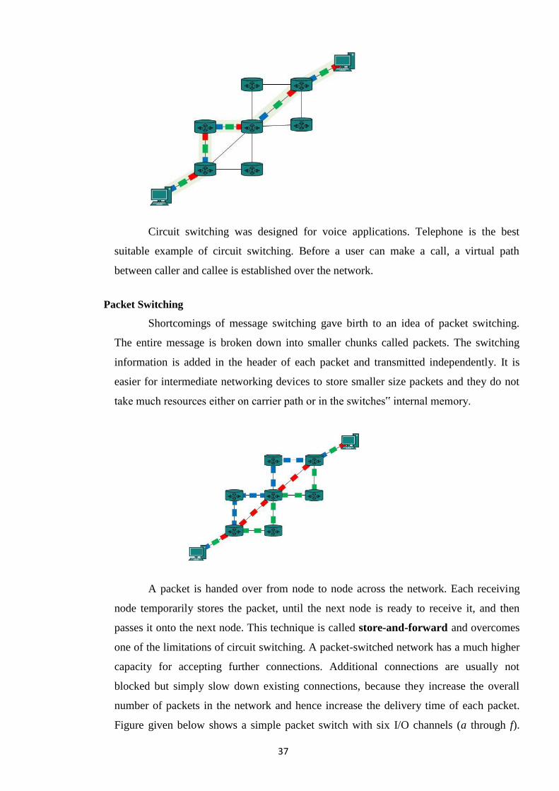
Packet Switching
Shortcomings of message switching gave birth to an idea of packet switching.
The entire message is broken down into smaller chunks called packets. The switching
information is added in the header of each packet and transmitted independently. It is
easier for intermediate networking devices to store smaller size packets and they do not
take much resources either on carrier path or in the switches‟ internal memory.
A packet is handed over from node to node across the network. Each receiving
node temporarily stores the packet, until the next node is ready to receive it, and then
passes it onto the next node. This technique is called store-and-forward and overcomes
one of the limitations of circuit switching. A packet-switched network has a much higher
capacity for accepting further connections. Additional connections are usually not
blocked but simply slow down existing connections, because they increase the overall
number of packets in the network and hence increase the delivery time of each packet.
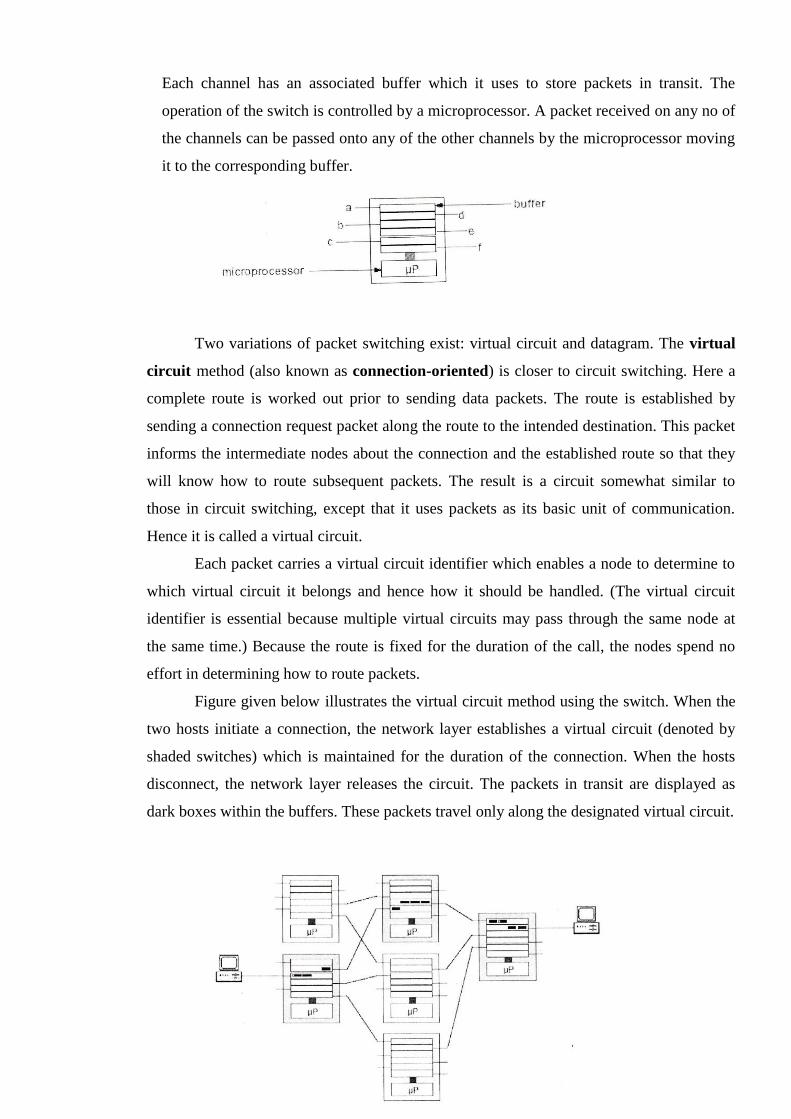
Figure given below shows a simple packet switch with six I/O channels (a through f).
38
Each channel has an associated buffer which it uses to store packets in transit. The
operation of the switch is controlled by a microprocessor. A packet received on any no of
the channels can be passed onto any of the other channels by the microprocessor moving
it to the corresponding buffer.
Two variations of packet switching exist: virtual circuit and datagram. The virtual
circuit method (also known as connection-oriented) is closer to circuit switching. Here a
complete route is worked out prior to sending data packets. The route is established by
sending a connection request packet along the route to the intended destination. This packet
informs the intermediate nodes about the connection and the established route so that they
will know how to route subsequent packets. The result is a circuit somewhat similar to
those in circuit switching, except that it uses packets as its basic unit of communication.
Hence it is called a virtual circuit.
Each packet carries a virtual circuit identifier which enables a node to determine to
which virtual circuit it belongs and hence how it should be handled. (The virtual circuit
identifier is essential because multiple virtual circuits may pass through the same node at
the same time.) Because the route is fixed for the duration of the call, the nodes spend no
effort in determining how to route packets.
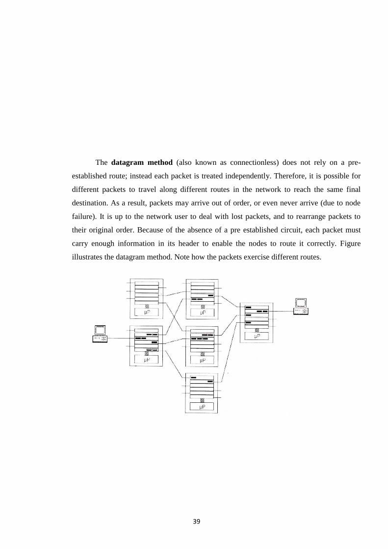
Figure given below illustrates the virtual circuit method using the switch. When the
two hosts initiate a connection, the network layer establishes a virtual circuit (denoted by
shaded switches) which is maintained for the duration of the connection. When the hosts
disconnect, the network layer releases the circuit. The packets in transit are displayed as
dark boxes within the buffers. These packets travel only along the designated virtual circuit.
39
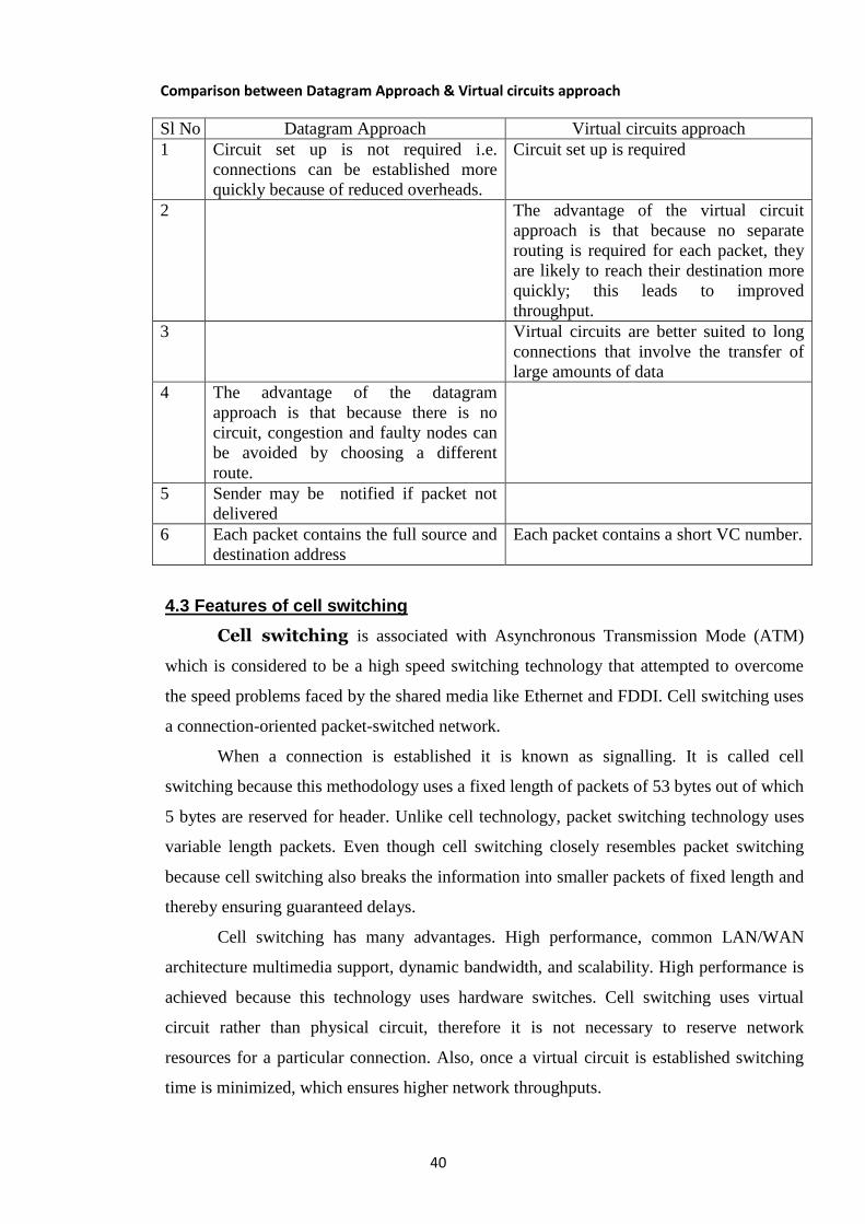
The datagram method (also known as connectionless) does not rely on a pre-
established route; instead each packet is treated independently. Therefore, it is possible for
different packets to travel along different routes in the network to reach the same final
destination. As a result, packets may arrive out of order, or even never arrive (due to node
failure). It is up to the network user to deal with lost packets, and to rearrange packets to
their original order. Because of the absence of a pre established circuit, each packet must
carry enough information in its header to enable the nodes to route it correctly. Figure
illustrates the datagram method. Note how the packets exercise different routes.
40
Comparison between Datagram Approach & Virtual circuits approach
Sl No Datagram Approach Virtual circuits approach
1 Circuit set up is not required i.e.
connections can be established more
quickly because of reduced overheads.
Circuit set up is required
2 The advantage of the virtual circuit
approach is that because no separate
routing is required for each packet, they
are likely to reach their destination more
quickly; this leads to improved
throughput.
3 Virtual circuits are better suited to long
connections that involve the transfer of
large amounts of data
4 The advantage of the datagram
approach is that because there is no
circuit, congestion and faulty nodes can
be avoided by choosing a different
route.
5 Sender may be notified if packet not
delivered
6 Each packet contains the full source and
destination address
Each packet contains a short VC number.
4.3 Features of cell switching
Cell switching is associated with Asynchronous Transmission Mode (ATM)
which is considered to be a high speed switching technology that attempted to overcome
the speed problems faced by the shared media like Ethernet and FDDI. Cell switching uses
a connection-oriented packet-switched network.
When a connection is established it is known as signalling. It is called cell
switching because this methodology uses a fixed length of packets of 53 bytes out of which
5 bytes are reserved for header. Unlike cell technology, packet switching technology uses
variable length packets. Even though cell switching closely resembles packet switching
because cell switching also breaks the information into smaller packets of fixed length and
thereby ensuring guaranteed delays.
Cell switching has many advantages. High performance, common LAN/WAN
architecture multimedia support, dynamic bandwidth, and scalability. High performance is
achieved because this technology uses hardware switches. Cell switching uses virtual
circuit rather than physical circuit, therefore it is not necessary to reserve network
resources for a particular connection. Also, once a virtual circuit is established switching
time is minimized, which ensures higher network throughputs.
41
The cell has a fixed length of 53 bytes out of which 48 bytes are reserved for
payloads and 5 bytes act as header. The header contains payload-type information, virtual-
circuit identifiers, and header error check.
Cell switching has features of circuit switching, as it is a connection-oriented
service where each connection during its set up phase creates a virtual circuit. The
connection, oriented virtual circuits for each phase allocates specified resources for
different streams of traffic. This makes cell switching a cost effective service.
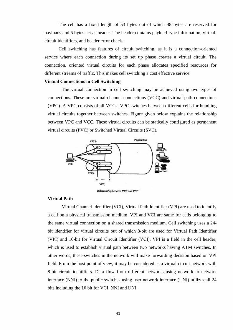
Virtual Connections in Cell Switching
The virtual connection in cell switching may be achieved using two types of
connections. These are virtual channel connections (VCC) and virtual path connections
(VPC). A VPC consists of all VCCs. VPC switches between different cells for bundling
virtual circuits together between switches. Figure given below explains the relationship
between VPC and VCC. These virtual circuits can be statically configured as permanent
virtual circuits (PVC) or Switched Virtual Circuits (SVC).
Virtual Path
Virtual Channel Identifier (VCI), Virtual Path Identifier (VPI) are used to identify
a cell on a physical transmission medium. VPI and VCI are same for cells belonging to
the same virtual connection on a shared transmission medium. Cell switching uses a 24-
bit identifier for virtual circuits out of which 8-bit are used for Virtual Path Identifier
(VPI) and 16-bit for Virtual Circuit Identifier (VCI). VPI is a field in the cell header,
which is used to establish virtual path between two networks having ATM switches. In
other words, these switches in the network will make forwarding decision based on VPI
field. From the host point of view, it may be considered as a virtual circuit network with
8-bit circuit identifiers. Data flow from different networks using network to network
interface (NNI) to the public switches using user network interface (UNI) utilizes all 24
bits including the 16 bit for VCI, NNI and UNI.
42
CHAPTER -5
Protocols
5.1 Define Data Communication Protocols.
1. A protocol is an agreed upon set or rules used by the sender and receiver to
communicate data.
2. A protocol is a set of rules that governs data communication.
3. A Protocol is a necessity in data communications without which the
communicating entities are like two persons trying to talk to each other in a
different language without know the other language.
5.2 Discuss the 7 layers of OSI model.
The OSI model is built of seven ordered layers:
– Layer-1: Physical
– Layer-2: Data Link
– Layer-3: Network
– Layer-4: Transport
– Layer-5: Session
– Layer-6: Presentation
– Layer-7: Application
The seven layers can be thought of as belonging to three sub groups
1. Network Support Layers (Layers 1-3)
Which deals with the physical aspects of moving data from one device to another.
2. User Support Layers (Layers 5-7)
Which Allow interoperability among unrelated software systems.
3. Layer-4 ensures end to end reliable data transmission.
Layer-1: Physical
1. First of three network support layers.
2. Concerned with physical transmission of data bits and ensures that a bit entering at
one end of the transmission media reaches the other end.
3. Deals with the mechanical and electrical specifications of the interface and
transmission medium e.g. Optical, coax, RF, twisted pair etc.
4. Defines the type of encoding i.e. how 0s and 1s are changed to signals.
5. Defines data rate / transmission rate i.e. defines the duration of a bit.
6. Responsible for synchronisation of sender and the receiver clocks.
43
7. Concerned with the connection of the devices to the medium.
8. Point-to-point configuration
–Multipoint configuration
9. Physical topology
–Mesh; Star; Ring; Bus
10. Transmission Mode
–Simplex; Half-Duplex; Full-Duplex.
Layer-2: Data Link
Second of three network support layers
1. Divides the bit stream received from network layer into manageable data units called
frames.
2. Transforms the physical layer to a reliable link by adding mechanism to detect and
retransmit damaged frames.
3. Responsible for physical addressing of the devices.
4. Responsible for link-by-link flow control and error free delivery of data.
5. Responsible for Media Access Control.
Layer-3: Network
Last of the three network support layers
1. Responsible for Source-to-Destination delivery of individual packets across multiple
links.
2. If two systems are connected to the same link there is usually no need for a network
layer.
3. Responsible for the unique logical addressing of the sender and the receiver
4. Responsible for routing of packets.
Layer-4: Transport
1. Responsible for Source-to-Destination delivery of the entire message.
2. Uses service-point address (port address) for end-to-end delivery.
3. Network layer gets each packet to correct computer, transport layer gets the entire
message to the correct process.
4. Responsible for segmenting a message into transmittable segments.
5. At the destination the message is correctly reassembled.
6. Utilises network layer to ensure reliable, sequenced data exchange.
7. Transport layer can be connection less or connection oriented.
– A connectionless transport layer treats each segment as an independent
packet.
– A connection oriented transport layer makes a connection with the
transport layer at the destination machine before delivering the packets.
– After all the data is transmitted, the connection is terminated.
44
8. Responsible for end-to-end flow control of data.
9. Responsible for end-to-end error control of data.
– Error correction is usually achieved through retransmission
Layer-5: Session
First of the three user support layers
1. It is the network dialog controller.
2. It establishes, maintains, and synchronises the interaction between communicating
systems.
3. It allows the communication between two processes to take place either in half-
duplex or full-duplex.
4. Allows a process to add checkpoints (sync points) into a stream of data.
Layer-6: Presentation
Second of the three user support layers
1. Concerned with the syntax and semantics of the information exchanged between
two systems.
2. At sender end, changes the information from sender dependent format into a
common format.
3. At the receiving end, changes the information from common format into its
receiver dependent format.
4. Responsible for encryption and decryption of sensitive information.
5. Responsible for data compression of the data to be transmitted.
Layer-7: Application
Top of the three user support layers
1. Enables the user, human or software, to access the network.
2. It provides user interfaces and support for services e.g. electronic mail, remote file
access and transfer, shared database management and other types of distributed
information services.
3. Specific services provided by the application layer includes
a. Network Virtual terminal.
Software version of a physical terminal.
Allows user to log on to a remote host.
b. File Transfer, Access and Management.
Allows user to access, retrieve, manage and control files in a remote computer.
c. Mail Services.
Provides basis for e-mail forwarding and storage.
d. Directory Services.
Provides distributed database sources and access for global information about
various services.
45
CHAPTER - 6
Local Area Network (LAN)
6.1 Name different types of LAN Components
Introduction
Computer networks are classified by scale, components, and connection method. LANs
(Local Area Network) are a relatively small network that connects computers in the same
physical location, usually within a building or a campus. As oppose to WAN (Wide Area
Networks) that consist of multiple LANs and can connect different countries together. How
a LAN is connected and what components it uses will determine how fast, reliable, and
accessible the network is.
Commercial Applications of LANs
LANs make up the larger Network configurations that are used today. These networks
are focus on handling the 1st, 2nd, and 3rd Layer of the Open Systems Interconnection
(OSI) standards. They are connected with category 5 (Cat5) cable and run IEEE 802.3
protocol to manage packets and frame size. Wireless LANs run IEEE 802.1X protocol
because of ―vulnerability to over-the-air signal interception‖. Network speeds can range
from 10 Mbps with IEEE 802.3 to 10 Gbps with IEEE 802.3ae. Network topologies that are
used include Bus, Ring, and Star. The most common topology in use is a combination of star
and bus. The bus makes up the backbone of the network with star networks branching out.
Switches, routers, hubs/wireless hubs, and servers are components that a LAN can contain.
Different types of LAN Components are
1.Router
Routers make the connection to the Internet for LANs. They use a configuration
table to decide where packets should go. This table keeps track of which connections lead
where, priorities for connections, and rules for handling traffic. They keep unnecessary
packets from using up all the bandwidth and makes sure information meets its destination.
Routers mainly deal with Layer 3 of the OSI protocol.
2. Hubs/Wireless Hubs
A hub is used to connect basic networks together. They are good for very small
networks and for shortening up distances packets have to travel. Hubs can be wireless and
allow wireless users to connect to the network. When transferring data between points, hubs
have to follow the Ethernet process called CSMA/CD as part of the IEEE standards. This
process is used to communicate across the network in order to avoid collisions of packets.
The result is that hubs have the share the bandwidth with all the devices connected to it. If
46
too many hubs are connected to together then this will cause problems for the network when
large files are being transferred.
3. Switches
Switches connect the network and give the device connected to the switch port the
full bandwidth. A fully switched network completely replaces all the hubs and allows the
network to maintain full duplex. There are not too many people who use fully switched
networks because switches are much more expensive then hubs. LAN switches use
spanning-tree protocol (STP) that is part of the IEEE 802.1d specification to determine the
best path for data to take [2]. Three widely used configurations of LAN switches are shared
memory, matrix, and bus architecture. Switches are focus on layer 2 of the OSI standard.
4. Servers
In order for a network to manage a large number of users it become necessary to
implement a server. A server is a high-powered computer connected to the network that
serves a special function for the network. For most LAN purposes a server serves as a
central point of information storage, file distribution and network managing. A web server
connected to a LAN could allow users to login from the Internet to access files. Small LANs
do not necessary need a server because a router can handle managing a small network.
Conclusions
A LAN consists of a group of computers and devices connected by switches and
hubs. For this LAN to gain access to the Internet it must contain a router. The speed of the
network greatly depends on the configuration of the switches and hubs. Servers can provide
specialized functions for the LAN network. There are other components that LANs can
contain like repeaters, buses, and gateways that help better connect networks and solve other
networking problems.
6.2 LAN Hardware & Software
A LAN is a combination of hardware and software.
The Hardware
The hardware consists of stations, transmission media, and connecting devices.
Stations:- Stations are actual devices that connect to the network. These can be
computers, printers, etc. Stations can be Local or Remote.
Transmission Media:- The transmission media is medium which connects the
network devices or it is the stuff through which signals travel. It can be guided as in the case
of a wire, or unguided as in the case of air (wireless).
47
Connecting Devices:- Besides the wires and stations, there are also connecting
devices. There are two ‗types‘:
1. Transceivers and all the other stuff that‘s used to connect a station to the medium.
2. Bridges, repeaters, etc., stuff that‘s used to connect segments of a LAN.
Servers.
– File servers.
– Print servers.
– Communications servers
Shared peripheral devices.
– Printers.
– Hard disk drives.
– CD-ROM drives.
– Modems.
The Software
There are two primary categories of software, the Operating System, and Application
Programs.
Network Operating System:- There needs to be some software at the operating
system level that manages the network connection. Most modern operating systems are
capable of using the network.
Application Programs:- The primary purpose of having a LAN is to allow several
application programs to talk to each other.
6.3 Transmission channel
The primary purpose of any LAN is the ability to transmit messages from one
networked device to another. Typically, such transmission channels are in the form of cables
physically connecting devices, although certain wireless transmission channels are available.
This physical infrastructure provides the foundation for all other devices and if it is not
functional and stable, it can be guaranteed that none of the other components will be able to
function as desired. The most common transmission channels are made up of some type of
cable—twisted pair, coaxial or optical fiber cable—and corresponding connection hardware.
Each of these is discussed in some detail already. A distinction must be made between the
transmission channel used locally and that used for remote access to the LAN:
• The local transmission channel is often limited to a single building, or at most to a
cluster of buildings closely co-located.
• The transmission channel used for remote access to a LAN is often part of the
public network.
48
6.4 Network Interface Cards (NICs)
Networked stations require a means to connect to the transmission channel. They do
so through a circuit board referred to as a Network Interface Card (NIC). The NIC allows a
device to be attached to a LAN and all LAN devices must be equipped with a NIC. The NIC
plugs into an available expansion slot in the device to be networked, and the transmission
medium is attached to a connector on the NIC. The details is available in chapter 1.5
6.5 LAN Operating system (software)
Once the physical building blocks of the LAN are put into place, the next step is
to make them functional. Software is needed for devices to function cooperatively and
effectively on the LAN.
There are three categories of software found on a LAN:
• The operating system of each attached server.
• The operating system of each attached station.
• Applications software accessed by LAN users.
a) Server operating systems
The server operating system is considered to be the brains of the network. It
controls the most critical aspects of network operations:
• Network performance.
• Network management.
• File integrity.
• Access security.
Each of the file servers on a LAN is controlled by an operating system, which
manages all activities taking place inside that file server. Unlike a station, which has only
one user accessing its files at any time, a file server must handle simultaneous requests
from multiple users. From its position in the file server, the server operating system must
satisfy station demands for programs, files, printing resources and communications
services while maintaining network security. In this capacity, a network operating system
found on a LAN server is very similar to the operating systems which run minicomputers
and mainframes.
b) Station operating systems
All PCs require an operating system to function. A station operating system is
designed for a stand-alone PC and provides access to programs, files, printing resources
and communications services found on that PC. When the PC becomes a station on a
LAN, the PC operating system remains unaware of the change. It does not recognize that
it now has access to LAN resources.
49
The station operating system must be made responsible for establishing the
connection with the network and the file server and control communications flow
between the station and the file server. Often, the modification to the station operating
system is software which is called a shell or shell software. The term comes from the
role this software plays on the station. After it is installed, it covers the operating system
running on the PC. When the user at the station requests a program or a file, sends a file
to a printer or sends a message to another station, the shell intercepts the request and
examines it. If the shell finds that the request can be handled by the station, it passes the
request to the station operating system. If the request is for LAN resources, the shell
sends it to the network interface card (NIC) in the station, which places the request on the
transmission channel and sends it to the server.
c) Applications software
Applications software is the term given to software used to perform a specific
task. The most common business applications are word processing, spreadsheet analysis
and database management.
In a LAN environment, the program files necessary to run these applications are
usually placed on the file server to permit shared access. Note that applications software
which resides on the hard disk of a station is not considered LAN software because it
cannot be accessed by other users, even though the stations themselves may be
connected. By contrast, an application software that resides on a file server but can only
be accessed by one individual for security reasons is considered to be LAN software
because it can be accessed by other users if the administrator grants them access
privileges.
i) Client/Server computing
A more recent method of sharing software is called client/server computing.
In client/ server computing, the applications software is created and sold for use
expressly on a LAN. Client/server software has two distinct parts—the client part
which runs on the user‘s station and the server part which is installed on the file
server.
With traditional applications software, all of the files are installed on the file
server. When a user runs the software, all of the needed program files are transferred
across the transmission channel to the station. When the user requests data files to
use with the program, those files must also be transferred.
In the client/server environment, when the user first makes a request for a
program, only the client portion of the program is sent to the station—not the entire
50
program. This client portion permits the user to make inquiries of data files. When
the server receives an inquiry from a station, rather than send the entire data file to
the station, it performs the inquiry locally and sends only the results to the station.
This dramatically reduces the traffic on the transmission channel.
An additional benefit of client/server computing is data integrity. Since the
data files never leave the server, there is less likelihood of file corruption.
ii) Groupware
A second type of application software has been introduced for the LAN
environment—groupware.
As the name implies, groupware is software designed specifically for use in a
LAN environment by a group of individuals with common goals and responsibilities.
This group may be one department, a project team or all employees in an
organization.
At its core, groupware manages the interactions between the members of the
team by tracking their schedules, by providing electronic mail boxes for
communication and by permitting people to work on documents simultaneously. The
software acts as a central administrator, allowing individuals to work on different
parts of a project while tracking progress as a whole.
Groupware is particularly useful to teams whose members are geographically
dispersed over many time zones. Instead of coordinating activities through ongoing
long-distance phone calls and/or periodic meetings, the members use the groupware
as their office.
iii) The People
Among the most important elements of a LAN are the people. The purpose of
a LAN is to allow the sharing of resources. This sharing is done by people—making
them an integral part of the structure.
With any LAN there are two groups of people involved—those who use the
resources and those who manage the resources.
d) The users
A user is defined as a person who makes use of the network resources. This
person uses a station to access the server(s) and work with the resources stored there.
Although the term user combines all of the individuals using a network, it is a varied
collection. Within the group will be individuals who are very knowledgeable about
PCs, those who know how to use only a single application package, and everyone
else in between. Due to the varying levels of competence, the LAN must be
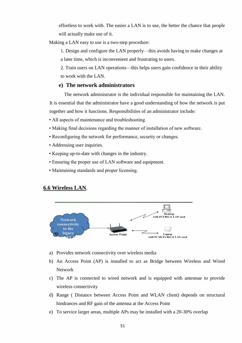
51
effortless to work with. The easier a LAN is to use, the better the chance that people
will actually make use of it.
Making a LAN easy to use is a two-step procedure:
1. Design and configure the LAN properly—this avoids having to make changes at
a later time, which is inconvenient and frustrating to users.
2. Train users on LAN operations—this helps users gain confidence in their ability
to work with the LAN.
e) The network administrators
The network administrator is the individual responsible for maintaining the LAN.
It is essential that the administrator have a good understanding of how the network is put
together and how it functions. Responsibilities of an administrator include:
• All aspects of maintenance and troubleshooting.
• Making final decisions regarding the manner of installation of new software.
• Reconfiguring the network for performance, security or changes.
• Addressing user inquiries.
• Keeping up-to-date with changes in the industry.
• Ensuring the proper use of LAN software and equipment.
• Maintaining standards and proper licensing.
6.6 Wireless LAN.
a) Provides network connectivity over wireless media
b) An Access Point (AP) is installed to act as Bridge between Wireless and Wired
Network
c) The AP is connected to wired network and is equipped with antennae to provide
wireless connectivity
d) Range ( Distance between Access Point and WLAN client) depends on structural
hindrances and RF gain of the antenna at the Access Point
e) To service larger areas, multiple APs may be installed with a 20-30% overlap
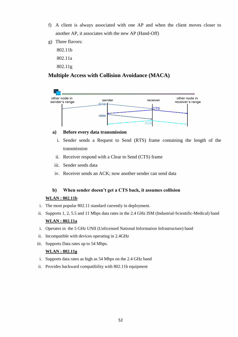
52
f) A client is always associated with one AP and when the client moves closer to
another AP, it associates with the new AP (Hand-Off)
g) Three flavors:
802.11b
802.11a
802.11g
Multiple Access with Collision Avoidance (MACA)
a) Before every data transmission
i. Sender sends a Request to Send (RTS) frame containing the length of the
transmission
ii. Receiver respond with a Clear to Send (CTS) frame
iii. Sender sends data
iv. Receiver sends an ACK; now another sender can send data
b) When sender doesn’t get a CTS back, it assumes collision
WLAN : 802.11b
i. The most popular 802.11 standard currently in deployment.
ii. Supports 1, 2, 5.5 and 11 Mbps data rates in the 2.4 GHz ISM (Industrial-Scientific-Medical) band
WLAN : 802.11a
i. Operates in the 5 GHz UNII (Unlicensed National Information Infrastructure) band
ii. Incompatible with devices operating in 2.4GHz
iii. Supports Data rates up to 54 Mbps.
WLAN : 802.11g
i. Supports data rates as high as 54 Mbps on the 2.4 GHz band
ii. Provides backward compatibility with 802.11b equipment
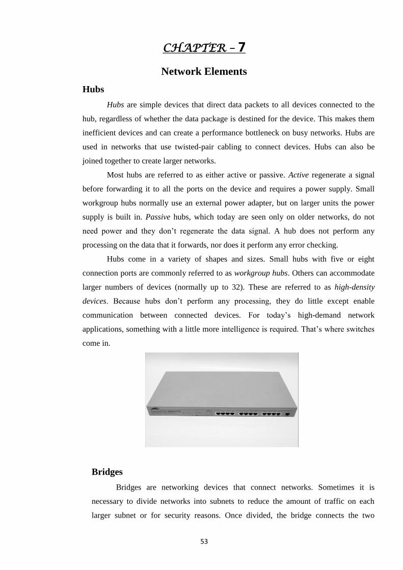
53
CHAPTER – 7
Network Elements
Hubs
Hubs are simple devices that direct data packets to all devices connected to the
hub, regardless of whether the data package is destined for the device. This makes them
inefficient devices and can create a performance bottleneck on busy networks. Hubs are
used in networks that use twisted-pair cabling to connect devices. Hubs can also be
joined together to create larger networks.
Most hubs are referred to as either active or passive. Active regenerate a signal
before forwarding it to all the ports on the device and requires a power supply. Small
workgroup hubs normally use an external power adapter, but on larger units the power
supply is built in. Passive hubs, which today are seen only on older networks, do not
need power and they don‘t regenerate the data signal. A hub does not perform any
processing on the data that it forwards, nor does it perform any error checking.
Hubs come in a variety of shapes and sizes. Small hubs with five or eight
connection ports are commonly referred to as workgroup hubs. Others can accommodate
larger numbers of devices (normally up to 32). These are referred to as high-density
devices. Because hubs don‘t perform any processing, they do little except enable
communication between connected devices. For today‘s high-demand network
applications, something with a little more intelligence is required. That‘s where switches
come in.
Bridges
Bridges are networking devices that connect networks. Sometimes it is
necessary to divide networks into subnets to reduce the amount of traffic on each
larger subnet or for security reasons. Once divided, the bridge connects the two
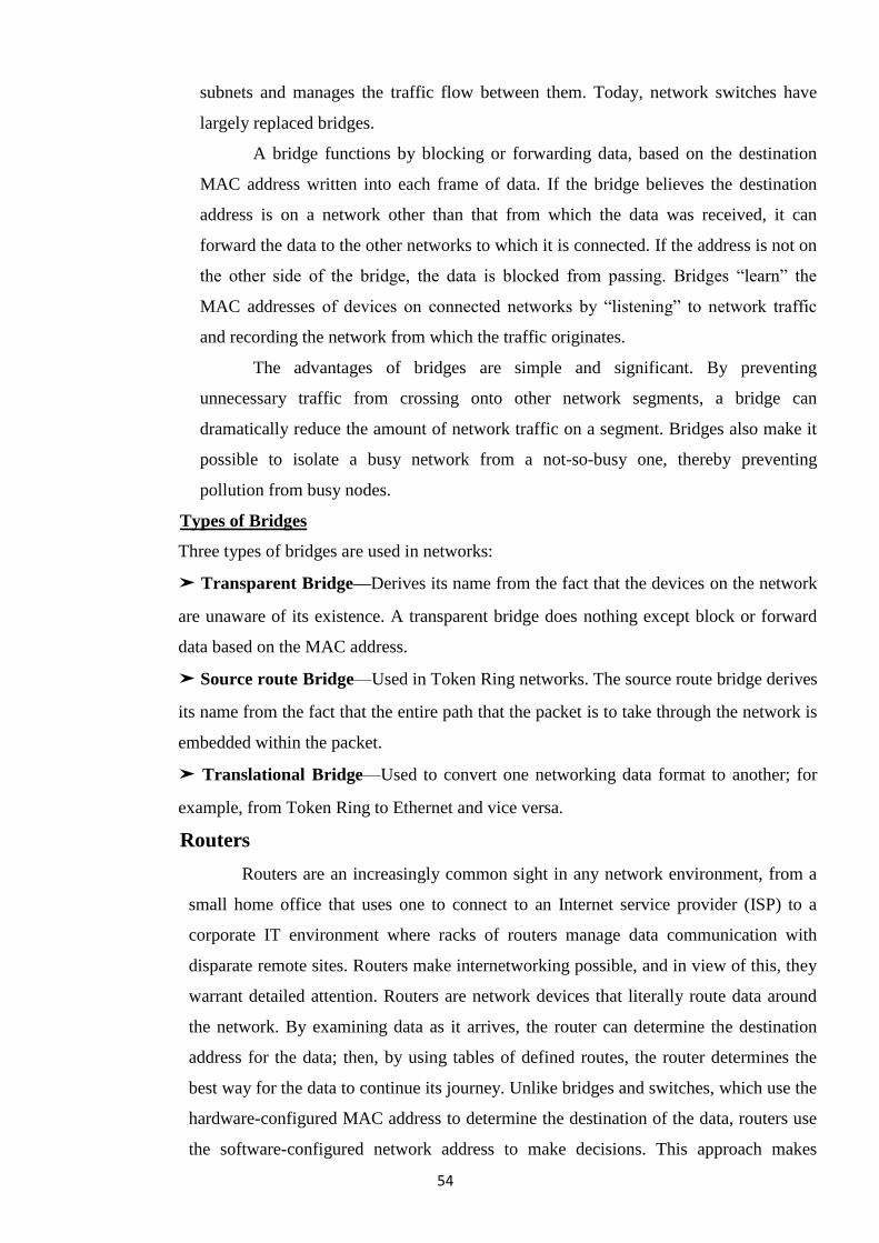
54
subnets and manages the traffic flow between them. Today, network switches have
largely replaced bridges.
A bridge functions by blocking or forwarding data, based on the destination
MAC address written into each frame of data. If the bridge believes the destination
address is on a network other than that from which the data was received, it can
forward the data to the other networks to which it is connected. If the address is not on
the other side of the bridge, the data is blocked from passing. Bridges ―learn‖ the
MAC addresses of devices on connected networks by ―listening‖ to network traffic
and recording the network from which the traffic originates.
The advantages of bridges are simple and significant. By preventing
unnecessary traffic from crossing onto other network segments, a bridge can
dramatically reduce the amount of network traffic on a segment. Bridges also make it
possible to isolate a busy network from a not-so-busy one, thereby preventing
pollution from busy nodes.
Types of Bridges
Three types of bridges are used in networks:
➤ Transparent Bridge—Derives its name from the fact that the devices on the network
are unaware of its existence. A transparent bridge does nothing except block or forward
data based on the MAC address.
➤ Source route Bridge—Used in Token Ring networks. The source route bridge derives
its name from the fact that the entire path that the packet is to take through the network is
embedded within the packet.
➤ Translational Bridge—Used to convert one networking data format to another; for
example, from Token Ring to Ethernet and vice versa.
Routers
Routers are an increasingly common sight in any network environment, from a
small home office that uses one to connect to an Internet service provider (ISP) to a
corporate IT environment where racks of routers manage data communication with
disparate remote sites. Routers make internetworking possible, and in view of this, they
warrant detailed attention. Routers are network devices that literally route data around
the network. By examining data as it arrives, the router can determine the destination
address for the data; then, by using tables of defined routes, the router determines the
best way for the data to continue its journey. Unlike bridges and switches, which use the
hardware-configured MAC address to determine the destination of the data, routers use
the software-configured network address to make decisions. This approach makes
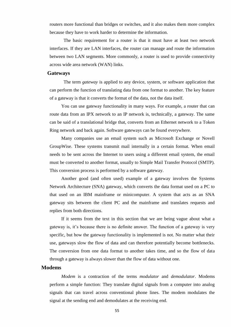
55
routers more functional than bridges or switches, and it also makes them more complex
because they have to work harder to determine the information.
The basic requirement for a router is that it must have at least two network
interfaces. If they are LAN interfaces, the router can manage and route the information
between two LAN segments. More commonly, a router is used to provide connectivity
across wide area network (WAN) links.
Gateways
The term gateway is applied to any device, system, or software application that
can perform the function of translating data from one format to another. The key feature
of a gateway is that it converts the format of the data, not the data itself.
You can use gateway functionality in many ways. For example, a router that can
route data from an IPX network to an IP network is, technically, a gateway. The same
can be said of a translational bridge that, converts from an Ethernet network to a Token
Ring network and back again. Software gateways can be found everywhere.
Many companies use an email system such as Microsoft Exchange or Novell
GroupWise. These systems transmit mail internally in a certain format. When email
needs to be sent across the Internet to users using a different email system, the email
must be converted to another format, usually to Simple Mail Transfer Protocol (SMTP).
This conversion process is performed by a software gateway.
Another good (and often used) example of a gateway involves the Systems
Network Architecture (SNA) gateway, which converts the data format used on a PC to
that used on an IBM mainframe or minicomputer. A system that acts as an SNA
gateway sits between the client PC and the mainframe and translates requests and
replies from both directions.
If it seems from the text in this section that we are being vague about what a
gateway is, it‘s because there is no definite answer. The function of a gateway is very
specific, but how the gateway functionality is implemented is not. No matter what their
use, gateways slow the flow of data and can therefore potentially become bottlenecks.
The conversion from one data format to another takes time, and so the flow of data
through a gateway is always slower than the flow of data without one.
Modems
Modem is a contraction of the terms modulator and demodulator. Modems
perform a simple function: They translate digital signals from a computer into analog
signals that can travel across conventional phone lines. The modem modulates the
signal at the sending end and demodulates at the receiving end.
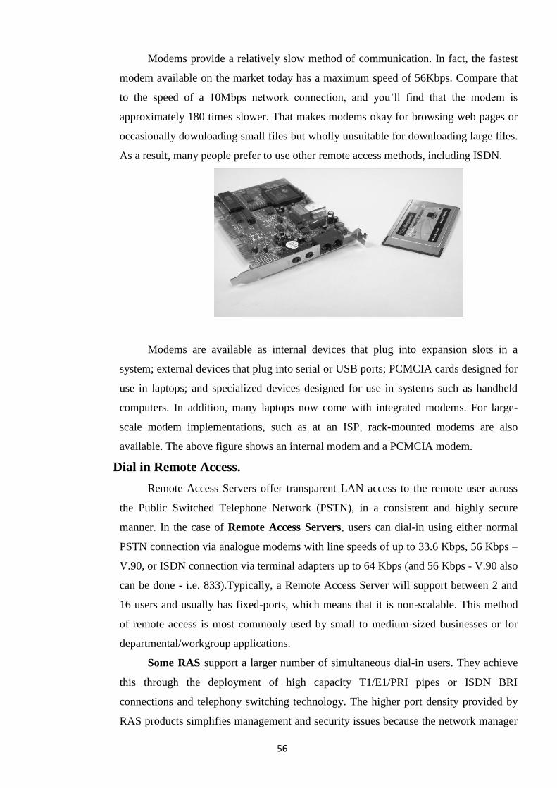
56
Modems provide a relatively slow method of communication. In fact, the fastest
modem available on the market today has a maximum speed of 56Kbps. Compare that
to the speed of a 10Mbps network connection, and you‘ll find that the modem is
approximately 180 times slower. That makes modems okay for browsing web pages or
occasionally downloading small files but wholly unsuitable for downloading large files.
As a result, many people prefer to use other remote access methods, including ISDN.
Modems are available as internal devices that plug into expansion slots in a
system; external devices that plug into serial or USB ports; PCMCIA cards designed for
use in laptops; and specialized devices designed for use in systems such as handheld
computers. In addition, many laptops now come with integrated modems. For large-
scale modem implementations, such as at an ISP, rack-mounted modems are also
available. The above figure shows an internal modem and a PCMCIA modem.
Dial in Remote Access.
Remote Access Servers offer transparent LAN access to the remote user across
the Public Switched Telephone Network (PSTN), in a consistent and highly secure
manner. In the case of Remote Access Servers, users can dial-in using either normal
PSTN connection via analogue modems with line speeds of up to 33.6 Kbps, 56 Kbps –
V.90, or ISDN connection via terminal adapters up to 64 Kbps (and 56 Kbps - V.90 also
can be done - i.e. 833).Typically, a Remote Access Server will support between 2 and
16 users and usually has fixed-ports, which means that it is non-scalable. This method
of remote access is most commonly used by small to medium-sized businesses or for
departmental/workgroup applications.
Some RAS support a larger number of simultaneous dial-in users. They achieve
this through the deployment of high capacity T1/E1/PRI pipes or ISDN BRI
connections and telephony switching technology. The higher port density provided by
RAS products simplifies management and security issues because the network manager
57
is dealing with a single point of access to open systems resources for all remote users.
Remote Access Servers are generally scalable, to accommodate future growth and will
invariably support both ISDN and analog calls on the same T1/E1/PRI or BRI line
(including 56 Kbps - V.90,V.34 - digital modem support).
In a rapidly evolving marketplace, the RAS solution is invariably the most cost
effective choice for the enterprise user. These types of remote access solution effectively
grant access to all the tools and technology of the open systems environment (Java,
Domino, Web Browsers), without any of the QoS and security issues associated with the
other forms of remote dial-in access.
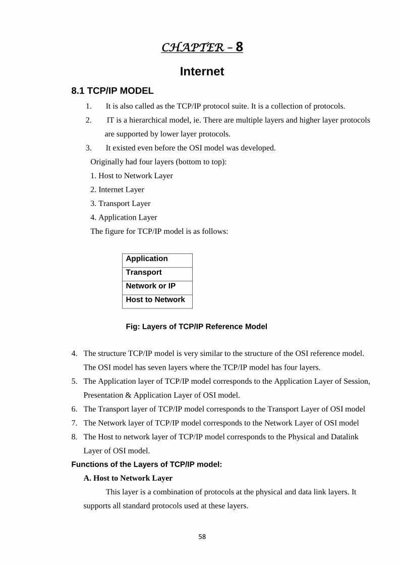
58
CHAPTER – 8
Internet
8.1 TCP/IP MODEL
1. It is also called as the TCP/IP protocol suite. It is a collection of protocols.
2. IT is a hierarchical model, ie. There are multiple layers and higher layer protocols
are supported by lower layer protocols.
3. It existed even before the OSI model was developed.
Originally had four layers (bottom to top):
1. Host to Network Layer
2. Internet Layer
3. Transport Layer
4. Application Layer
The figure for TCP/IP model is as follows:
Application
Transport
Network or IP
Host to Network
Fig: Layers of TCP/IP Reference Model
4. The structure TCP/IP model is very similar to the structure of the OSI reference model.
The OSI model has seven layers where the TCP/IP model has four layers.
5. The Application layer of TCP/IP model corresponds to the Application Layer of Session,
Presentation & Application Layer of OSI model.
6. The Transport layer of TCP/IP model corresponds to the Transport Layer of OSI model
7. The Network layer of TCP/IP model corresponds to the Network Layer of OSI model
8. The Host to network layer of TCP/IP model corresponds to the Physical and Datalink
Layer of OSI model.
Functions of the Layers of TCP/IP model:
A. Host to Network Layer
This layer is a combination of protocols at the physical and data link layers. It
supports all standard protocols used at these layers.
59
B. Network Layer or IP
1. Also called as the Internetwork Layer (IP). It holds the IP protocol which is a
network layer protocol and is responsible for source to destination transmission of
data.
2. The Internetworking Protocol (IP) is a connection-less & unreliable protocol.
3. It is a best effort delivery service. i.e. there is no error checking in IP, it simply
sends the data and relies on its underlying layers to get the data transmitted to the
destination.
4. IP transports data by dividing it into packets or datagrams of same size. Each
packet is independent of the other and can be transported across different routes
and can arrive out of order at the receiver.
5. In other words, since there is no connection set up between the sender and the
receiver the packets find the best possible path and reach the destination. Hence,
the word connection-less.
6. The packets may get dropped during transmission along various routes. Since IP
does not make any guarantee about the delivery of the data its call an unreliable
protocol.
7. Even if it is unreliable IP cannot be considered weak and useless; since it provides
only the functionality that is required for transmitting data thereby giving
maximum efficiency. Since there is no mechanism of error detection or correction
in IP, there will be no delay introduced on a medium where there is no error at all.
8. IP is a combination of four protocols:
1. ARP
2. RARP
3. ICMP
4. IGMP
1. ARP – Address Resolution Protocol
I. It is used to resolve the physical address of a device on a network, where its
logical address is known.
II. Physical address is the 48 bit address that is imprinted on the NIC or LAN card,
Logical address is the Internet Address or commonly known as IP address that is
used to uniquely & universally identify a device.
2. RARP– Reverse Address Resolution Protocol
60
I. It is used by a device on the network to find its Internet address when it knows
its physical address.
3. ICMP- Internet Control Message Protocol
I. It is a signaling mechanism used to inform the sender about datagram problems
that occur during transit.
II. It is used by intermediate devices.
III. In case and intermediate device like a gateway encounters any problem like a
corrupt datagram it may use ICMP to send a message to the sender of the
datagram.
4. IGMP- Internet Group Message Protocol
I. It is a mechanism that allows to send the same message to a group of recipients.
C. Transport Layer
Transport layer protocols are responsible for transmission of data running on a process
of one machine to the correct process running on another machine.
The transport layer contains three protocols:
1. TCP
2. UDP
3. SCTP
1. TCP – Transmission Control Protocol
I. TCP is a reliable connection-oriented, reliable protocol. i.e. a connection is
established between the sender and receiver before the data can be transmitted.
II. It divides the data it receives from the upper layer into segments and tags a
sequence number to each segment which is used at the receiving end for
reordering of data.
2. UDP – User Datagram Protocol
I. UDP is a simple protocol used for process to process transmission.
II. It is an unreliable, connectionless protocol for applications that do not require
flow control or error control.
III. It simply adds port address, checksum and length information to the data it
receives from the upper layer.
3. SCTP – Stream Control Transmission Protocol
I. SCTP is a relatively new protocol added to the transport layer of TCP/IP
protocol suite.
II. It combines the features of TCP and UDP.
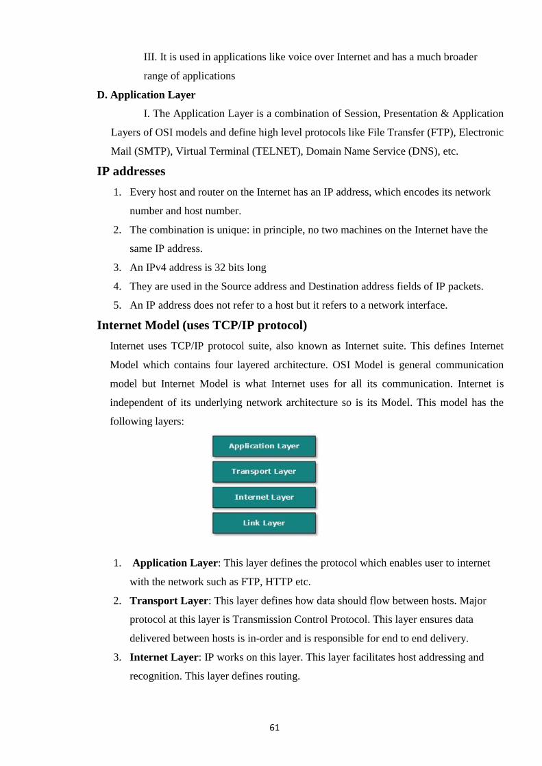
61
III. It is used in applications like voice over Internet and has a much broader
range of applications
D. Application Layer
I. The Application Layer is a combination of Session, Presentation & Application
Layers of OSI models and define high level protocols like File Transfer (FTP), Electronic
Mail (SMTP), Virtual Terminal (TELNET), Domain Name Service (DNS), etc.
IP addresses
1. Every host and router on the Internet has an IP address, which encodes its network
number and host number.
2. The combination is unique: in principle, no two machines on the Internet have the
same IP address.
3. An IPv4 address is 32 bits long
4. They are used in the Source address and Destination address fields of IP packets.
5. An IP address does not refer to a host but it refers to a network interface.
Internet Model (uses TCP/IP protocol)
Internet uses TCP/IP protocol suite, also known as Internet suite. This defines Internet
Model which contains four layered architecture. OSI Model is general communication
model but Internet Model is what Internet uses for all its communication. Internet is
independent of its underlying network architecture so is its Model. This model has the
following layers:
1. Application Layer: This layer defines the protocol which enables user to internet
with the network such as FTP, HTTP etc.
2. Transport Layer: This layer defines how data should flow between hosts. Major
protocol at this layer is Transmission Control Protocol. This layer ensures data
delivered between hosts is in-order and is responsible for end to end delivery.
3. Internet Layer: IP works on this layer. This layer facilitates host addressing and
recognition. This layer defines routing.
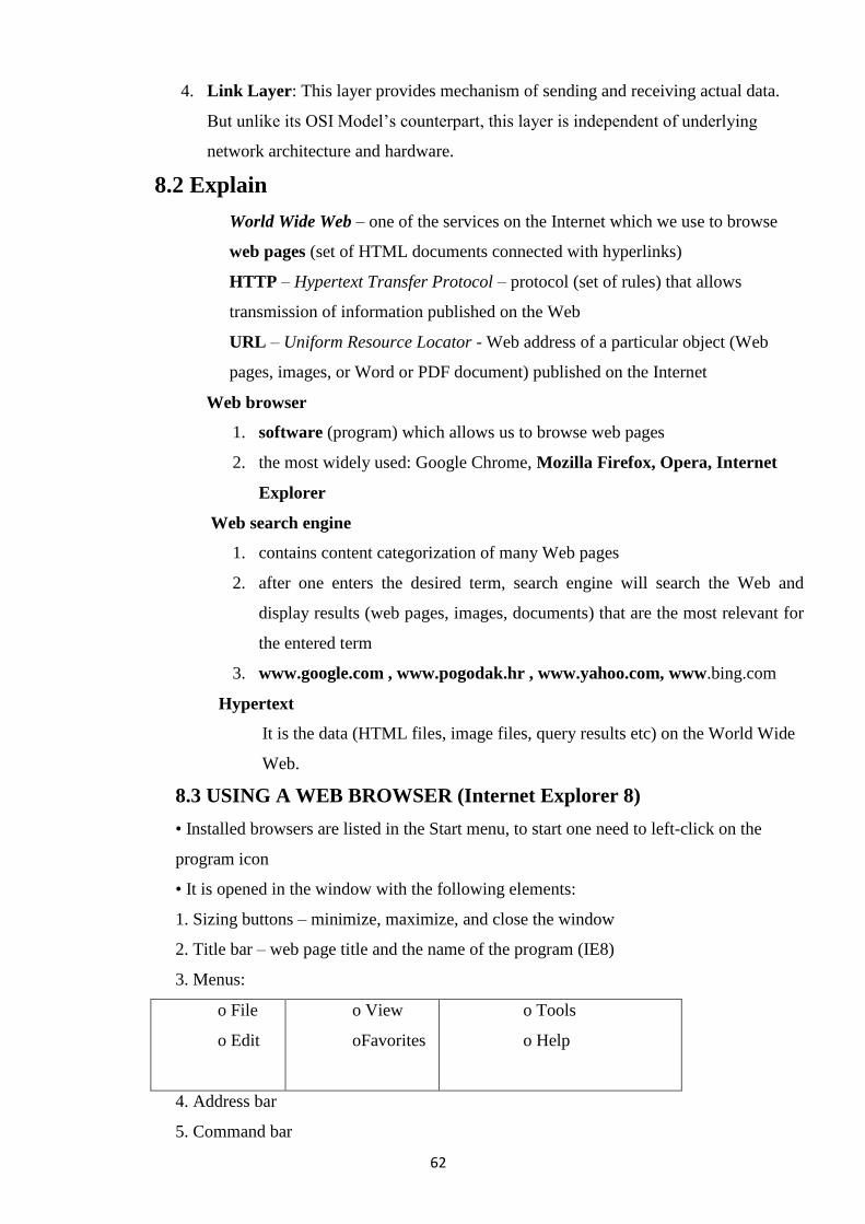
62
4. Link Layer: This layer provides mechanism of sending and receiving actual data.
But unlike its OSI Model‘s counterpart, this layer is independent of underlying
network architecture and hardware.
8.2 Explain
World Wide Web – one of the services on the Internet which we use to browse
web pages (set of HTML documents connected with hyperlinks)
HTTP – Hypertext Transfer Protocol – protocol (set of rules) that allows
transmission of information published on the Web
URL – Uniform Resource Locator - Web address of a particular object (Web
pages, images, or Word or PDF document) published on the Internet
Web browser
1. software (program) which allows us to browse web pages
2. the most widely used: Google Chrome, Mozilla Firefox, Opera, Internet
Explorer
Web search engine
1. contains content categorization of many Web pages
2. after one enters the desired term, search engine will search the Web and
display results (web pages, images, documents) that are the most relevant for
the entered term
3. www.google.com , www.pogodak.hr , www.yahoo.com, www.bing.com
Hypertext
It is the data (HTML files, image files, query results etc) on the World Wide
Web.
8.3 USING A WEB BROWSER (Internet Explorer 8)
• Installed browsers are listed in the Start menu, to start one need to left-click on the
program icon
• It is opened in the window with the following elements:
1. Sizing buttons – minimize, maximize, and close the window
2. Title bar – web page title and the name of the program (IE8)
3. Menus:
o File
o Edit
o View
oFavorites
o Tools
o Help
4. Address bar
5. Command bar
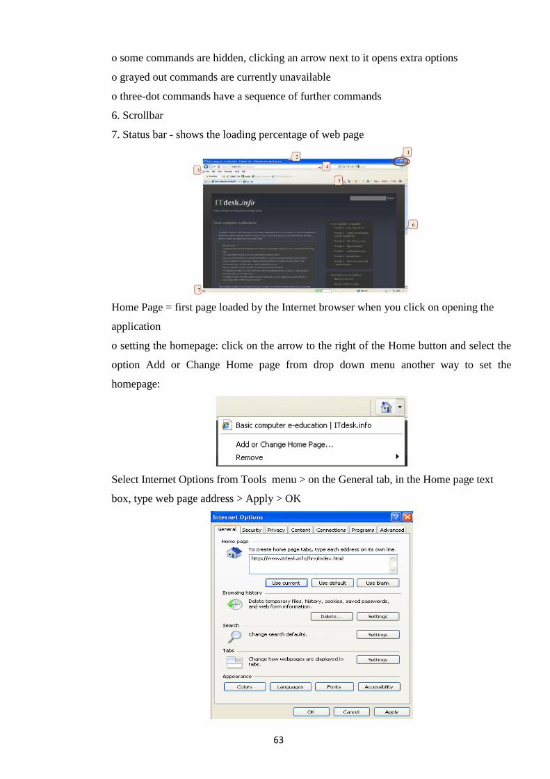
63
o some commands are hidden, clicking an arrow next to it opens extra options
o grayed out commands are currently unavailable
o three-dot commands have a sequence of further commands
6. Scrollbar
7. Status bar - shows the loading percentage of web page
Home Page = first page loaded by the Internet browser when you click on opening the
application
o setting the homepage: click on the arrow to the right of the Home button and select the
option Add or Change Home page from drop down menu another way to set the
homepage:
Select Internet Options from Tools menu > on the General tab, in the Home page text
box, type web page address > Apply > OK
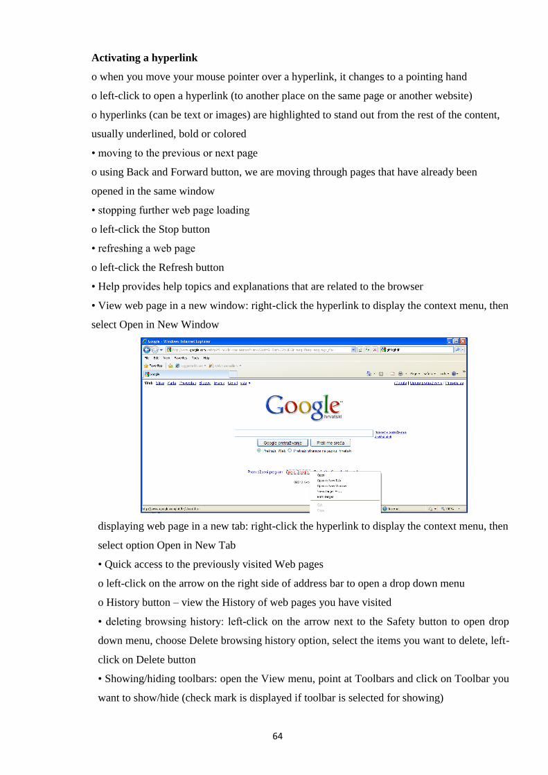
64
Activating a hyperlink
o when you move your mouse pointer over a hyperlink, it changes to a pointing hand
o left-click to open a hyperlink (to another place on the same page or another website)
o hyperlinks (can be text or images) are highlighted to stand out from the rest of the content,
usually underlined, bold or colored
• moving to the previous or next page
o using Back and Forward button, we are moving through pages that have already been
opened in the same window
• stopping further web page loading
o left-click the Stop button
• refreshing a web page
o left-click the Refresh button
• Help provides help topics and explanations that are related to the browser
• View web page in a new window: right-click the hyperlink to display the context menu, then
select Open in New Window
displaying web page in a new tab: right-click the hyperlink to display the context menu, then
select option Open in New Tab
• Quick access to the previously visited Web pages
o left-click on the arrow on the right side of address bar to open a drop down menu
o History button – view the History of web pages you have visited
• deleting browsing history: left-click on the arrow next to the Safety button to open drop
down menu, choose Delete browsing history option, select the items you want to delete, left-
click on Delete button
• Showing/hiding toolbars: open the View menu, point at Toolbars and click on Toolbar you
want to show/hide (check mark is displayed if toolbar is selected for showing)
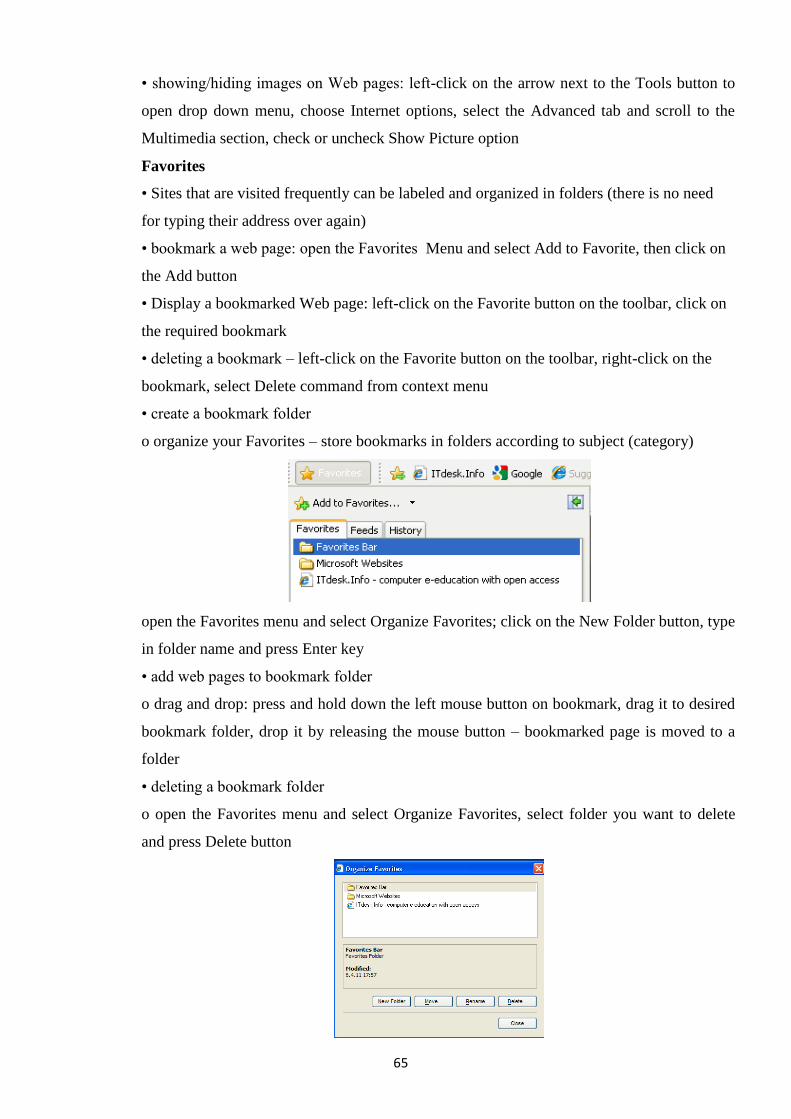
65
• showing/hiding images on Web pages: left-click on the arrow next to the Tools button to
open drop down menu, choose Internet options, select the Advanced tab and scroll to the
Multimedia section, check or uncheck Show Picture option
Favorites
• Sites that are visited frequently can be labeled and organized in folders (there is no need
for typing their address over again)
• bookmark a web page: open the Favorites Menu and select Add to Favorite, then click on
the Add button
• Display a bookmarked Web page: left-click on the Favorite button on the toolbar, click on
the required bookmark
• deleting a bookmark – left-click on the Favorite button on the toolbar, right-click on the
bookmark, select Delete command from context menu
• create a bookmark folder
o organize your Favorites – store bookmarks in folders according to subject (category)
open the Favorites menu and select Organize Favorites; click on the New Folder button, type
in folder name and press Enter key
• add web pages to bookmark folder
o drag and drop: press and hold down the left mouse button on bookmark, drag it to desired
bookmark folder, drop it by releasing the mouse button – bookmarked page is moved to a
folder
• deleting a bookmark folder
o open the Favorites menu and select Organize Favorites, select folder you want to delete
and press Delete button
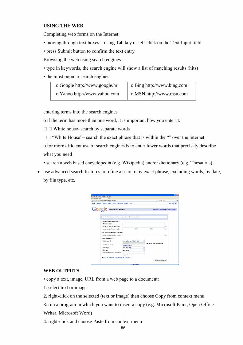
66
USING THE WEB
Completing web forms on the Internet
• moving through text boxes – using Tab key or left-click on the Text Input field
• press Submit button to confirm the text entry
Browsing the web using search engines
• type in keywords, the search engine will show a list of matching results (hits)
• the most popular search engines:
o Google http://www.google.hr
o Yahoo http://www.yahoo.com
o Bing http://www.bing.com
o MSN http://www.msn.com
entering terms into the search engines
o if the term has more than one word, it is important how you enter it:
White house – search by separate words
―White House‖ – search the exact phrase that is within the ―‖ over the internet
o for more efficient use of search engines is to enter fewer words that precisely describe
what you need
• search a web based encyclopedia (e.g. Wikipedia) and/or dictionary (e.g. Thesaurus)
use advanced search features to refine a search: by exact phrase, excluding words, by date,
by file type, etc.
WEB OUTPUTS
• copy a text, image, URL from a web page to a document:
1. select text or image
2. right-click on the selected (text or image) then choose Copy from context menu
3. run a program in which you want to insert a copy (e.g. Microsoft Paint, Open Office
Writer, Microsoft Word)
4. right-click and choose Paste from context menu
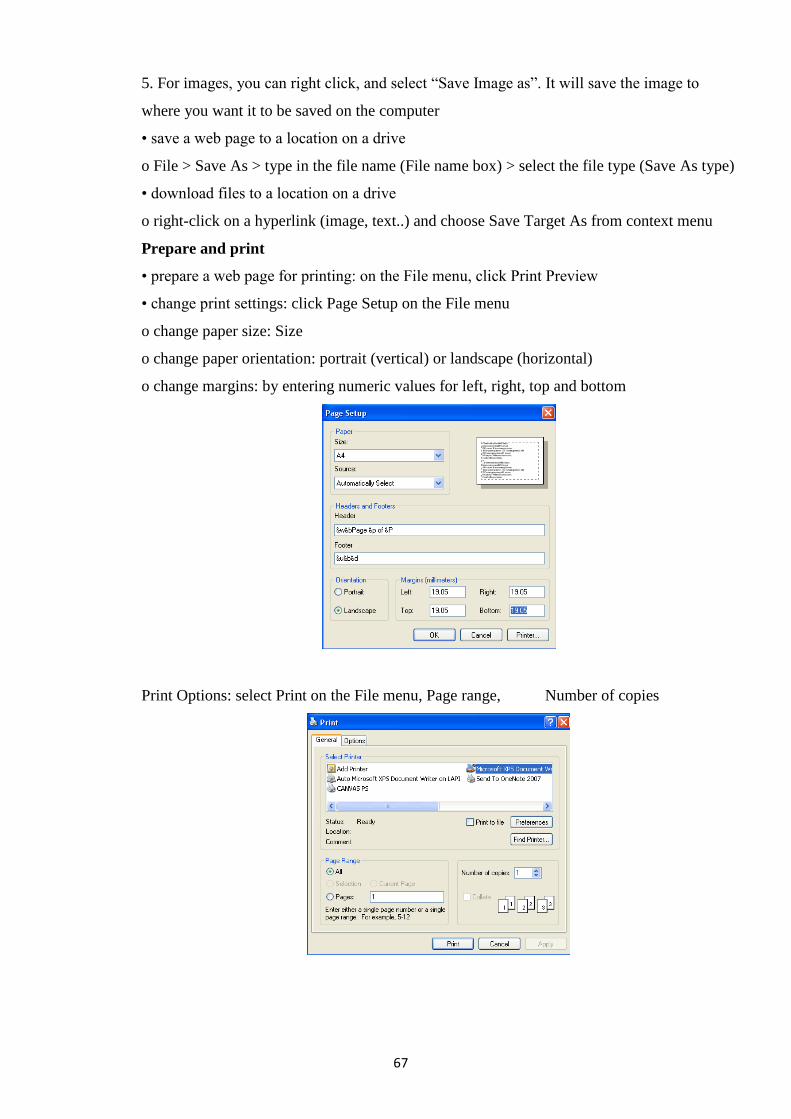
67
5. For images, you can right click, and select ―Save Image as‖. It will save the image to
where you want it to be saved on the computer
• save a web page to a location on a drive
o File > Save As > type in the file name (File name box) > select the file type (Save As type)
• download files to a location on a drive
o right-click on a hyperlink (image, text..) and choose Save Target As from context menu
Prepare and print
• prepare a web page for printing: on the File menu, click Print Preview
• change print settings: click Page Setup on the File menu
o change paper size: Size
o change paper orientation: portrait (vertical) or landscape (horizontal)
o change margins: by entering numeric values for left, right, top and bottom
Print Options: select Print on the File menu, Page range, Number of copies
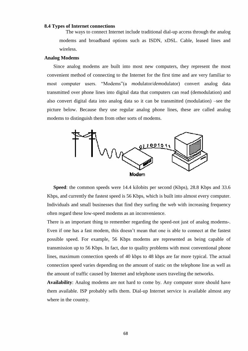
68
8.4 Types of Internet connections
The ways to connect Internet include traditional dial-up access through the analog
modems and broadband options such as ISDN, xDSL. Cable, leased lines and
wireless.
Analog Modems
Since analog modems are built into most new computers, they represent the most
convenient method of connecting to the Internet for the first time and are very familiar to
most computer users. ―Modems‖(a modulator/demodulator) convert analog data
transmitted over phone lines into digital data that computers can read (demodulation) and
also convert digital data into analog data so it can be transmitted (modulation) –see the
picture below. Because they use regular analog phone lines, these are called analog
modems to distinguish them from other sorts of modems.
Speed: the common speeds were 14.4 kilobits per second (Kbps), 28.8 Kbps and 33.6
Kbps, and currently the fastest speed is 56 Kbps, which is built into almost every computer.
Individuals and small businesses that find they surfing the web with increasing frequency
often regard these low-speed modems as an inconvenience.
There is an important thing to remember regarding the speed-not just of analog modems-.
Even if one has a fast modem, this doesn‘t mean that one is able to connect at the fastest
possible speed. For example, 56 Kbps modems are represented as being capable of
transmission up to 56 Kbps. In fact, due to quality problems with most conventional phone
lines, maximum connection speeds of 40 kbps to 48 kbps are far more typical. The actual
connection speed varies depending on the amount of static on the telephone line as well as
the amount of traffic caused by Internet and telephone users traveling the networks.
Availability: Analog modems are not hard to come by. Any computer store should have
them available. ISP probably sells them. Dial-up Internet service is available almost any
where in the country.
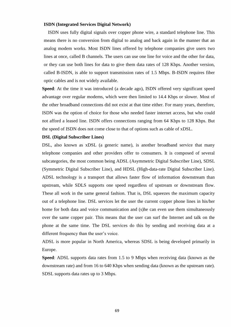
69
ISDN (Integrated Services Digital Network)
ISDN uses fully digital signals over copper phone wire, a standard telephone line. This
means there is no conversion from digital to analog and back again in the manner that an
analog modem works. Most ISDN lines offered by telephone companies give users two
lines at once, called B channels. The users can use one line for voice and the other for data,
or they can use both lines for data to give them data rates of 128 Kbps. Another version,
called B-ISDN, is able to support transmission rates of 1.5 Mbps. B-ISDN requires fiber
optic cables and is not widely available.
Speed: At the time it was introduced (a decade ago), ISDN offered very significant speed
advantage over regular modems, which were then limited to 14.4 Kbps or slower. Most of
the other broadband connections did not exist at that time either. For many years, therefore,
ISDN was the option of choice for those who needed faster internet access, but who could
not afford a leased line. ISDN offers connections ranging from 64 Kbps to 128 Kbps. But
the speed of ISDN does not come close to that of options such as cable of xDSL.
DSL (Digital Subscriber Lines)
DSL, also known as xDSL (a generic name), is another broadband service that many
telephone companies and other providers offer to consumers. It is composed of several
subcategories, the most common being ADSL (Asymmetric Digital Subscriber Line), SDSL
(Symmetric Digital Subscriber Line), and HDSL (High-data-rate Digital Subscriber Line).
ADSL technology is a transport that allows faster flow of information downstream than
upstream, while SDLS supports one speed regardless of upstream or downstream flow.
These all work in the same general fashion. That is, DSL squeezes the maximum capacity
out of a telephone line. DSL services let the user the current copper phone lines in his/her
home for both data and voice communication and (s)he can even use them simultaneously
over the same copper pair. This means that the user can surf the Internet and talk on the
phone at the same time. The DSL services do this by sending and receiving data at a
different frequency than the user‘s voice.
ADSL is more popular in North America, whereas SDSL is being developed primarily in
Europe.
Speed: ADSL supports data rates from 1.5 to 9 Mbps when receiving data (known as the
downstream rate) and from 16 to 640 Kbps when sending data (known as the upstream rate).
SDSL supports data rates up to 3 Mbps.
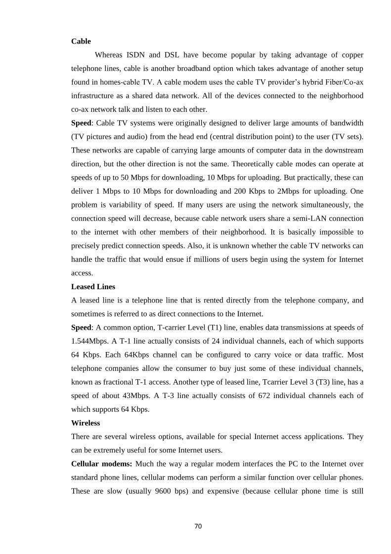
70
Cable
Whereas ISDN and DSL have become popular by taking advantage of copper
telephone lines, cable is another broadband option which takes advantage of another setup
found in homes-cable TV. A cable modem uses the cable TV provider‘s hybrid Fiber/Co-ax
infrastructure as a shared data network. All of the devices connected to the neighborhood
co-ax network talk and listen to each other.
Speed: Cable TV systems were originally designed to deliver large amounts of bandwidth
(TV pictures and audio) from the head end (central distribution point) to the user (TV sets).
These networks are capable of carrying large amounts of computer data in the downstream
direction, but the other direction is not the same. Theoretically cable modes can operate at
speeds of up to 50 Mbps for downloading, 10 Mbps for uploading. But practically, these can
deliver 1 Mbps to 10 Mbps for downloading and 200 Kbps to 2Mbps for uploading. One
problem is variability of speed. If many users are using the network simultaneously, the
connection speed will decrease, because cable network users share a semi-LAN connection
to the internet with other members of their neighborhood. It is basically impossible to
precisely predict connection speeds. Also, it is unknown whether the cable TV networks can
handle the traffic that would ensue if millions of users begin using the system for Internet
access.
Leased Lines
A leased line is a telephone line that is rented directly from the telephone company, and
sometimes is referred to as direct connections to the Internet.
Speed: A common option, T-carrier Level (T1) line, enables data transmissions at speeds of
1.544Mbps. A T-1 line actually consists of 24 individual channels, each of which supports
64 Kbps. Each 64Kbps channel can be configured to carry voice or data traffic. Most
telephone companies allow the consumer to buy just some of these individual channels,
known as fractional T-1 access. Another type of leased line, Tcarrier Level 3 (T3) line, has a
speed of about 43Mbps. A T-3 line actually consists of 672 individual channels each of
which supports 64 Kbps.
Wireless
There are several wireless options, available for special Internet access applications. They
can be extremely useful for some Internet users.
Cellular modems: Much the way a regular modem interfaces the PC to the Internet over
standard phone lines, cellular modems can perform a similar function over cellular phones.
These are slow (usually 9600 bps) and expensive (because cellular phone time is still
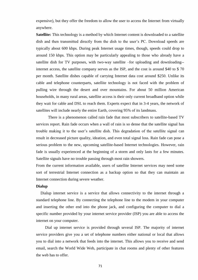
71
expensive), but they offer the freedom to allow the user to access the Internet from virtually
anywhere.
Satellite: This technology is a method by which Internet content is downloaded to a satellite
dish and then transmitted directly from the dish to the user‘s PC. Download speeds are
typically about 600 kbps. During peak Internet usage times, though, speeds could drop to
around 150 kbps. This option may be particularly appealing to those who already have a
satellite dish for TV purposes, with two-way satellite –for uploading and downloading--
internet access, the satellite company serves as the ISP, and the cost is around $40 to $ 70
per month. Satellite dishes capable of carrying Internet data cost around $250. Unlike its
cable and telephone counterparts, satellite technology is not faced with the problem of
pulling wire through the desert and over mountains. For about 50 million American
households, in many rural areas, satellite access is their only current broadband option while
they wait for cable and DSL to reach them. Experts expect that in 3-4 years, the network of
satellites will include nearly the entire Earth, covering 95% of its landmass.
There is a phenomenon called rain fade that most subscribers to satellite-based TV
services report. Rain fade occurs when a wall of rain is so dense that the satellite signal has
trouble making it to the user‘s satellite dish. This degradation of the satellite signal can
result in decreased picture quality, ideation, and even total signal loss. Rain fade can pose a
serious problem to the new, upcoming satellite-based Internet technologies. However, rain
fade is usually experienced at the beginning of a storm and only lasts for a few minutes.
Satellite signals have no trouble passing through most rain showers.
From the current information available, users of satellite Internet services may need some
sort of terrestrial Internet connection as a backup option so that they can maintain an
Internet connection during severe weather.
Dialup
Dialup internet service is a service that allows connectivity to the internet through a
standard telephone line. By connecting the telephone line to the modem in your computer
and inserting the other end into the phone jack, and configuring the computer to dial a
specific number provided by your internet service provider (ISP) you are able to access the
internet on your computer.
Dial up internet service is provided through several ISP. The majority of internet
service providers give you a set of telephone numbers either national or local that allows
you to dial into a network that feeds into the internet. This allows you to receive and send
email, search the World Wide Web, participate in chat rooms and plenty of other features
the web has to offer.
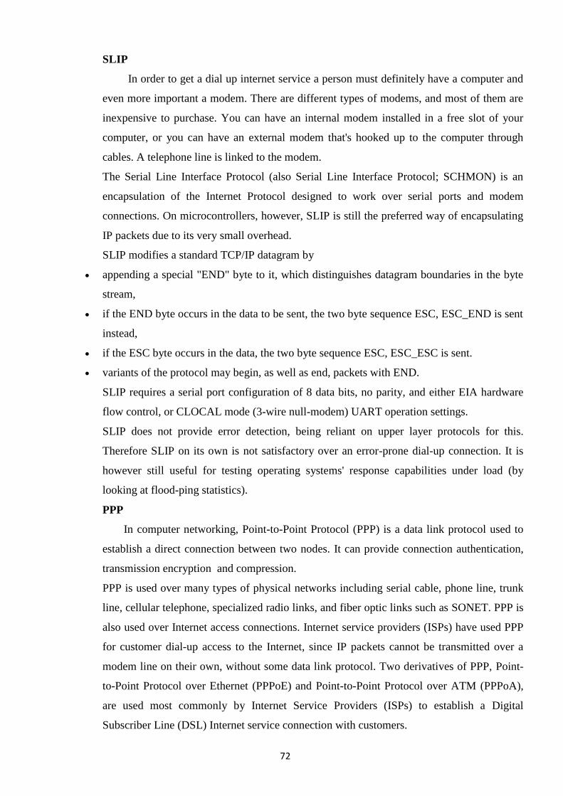
72
SLIP
In order to get a dial up internet service a person must definitely have a computer and
even more important a modem. There are different types of modems, and most of them are
inexpensive to purchase. You can have an internal modem installed in a free slot of your
computer, or you can have an external modem that's hooked up to the computer through
cables. A telephone line is linked to the modem.
The Serial Line Interface Protocol (also Serial Line Interface Protocol; SCHMON) is an
encapsulation of the Internet Protocol designed to work over serial ports and modem
connections. On microcontrollers, however, SLIP is still the preferred way of encapsulating
IP packets due to its very small overhead.
SLIP modifies a standard TCP/IP datagram by
appending a special "END" byte to it, which distinguishes datagram boundaries in the byte
stream,
if the END byte occurs in the data to be sent, the two byte sequence ESC, ESC_END is sent
instead,
if the ESC byte occurs in the data, the two byte sequence ESC, ESC_ESC is sent.
variants of the protocol may begin, as well as end, packets with END.
SLIP requires a serial port configuration of 8 data bits, no parity, and either EIA hardware
flow control, or CLOCAL mode (3-wire null-modem) UART operation settings.
SLIP does not provide error detection, being reliant on upper layer protocols for this.
Therefore SLIP on its own is not satisfactory over an error-prone dial-up connection. It is
however still useful for testing operating systems' response capabilities under load (by
looking at flood-ping statistics).
PPP
In computer networking, Point-to-Point Protocol (PPP) is a data link protocol used to
establish a direct connection between two nodes. It can provide connection authentication,
transmission encryption and compression.
PPP is used over many types of physical networks including serial cable, phone line, trunk
line, cellular telephone, specialized radio links, and fiber optic links such as SONET. PPP is
also used over Internet access connections. Internet service providers (ISPs) have used PPP
for customer dial-up access to the Internet, since IP packets cannot be transmitted over a
modem line on their own, without some data link protocol. Two derivatives of PPP, Point-
to-Point Protocol over Ethernet (PPPoE) and Point-to-Point Protocol over ATM (PPPoA),
are used most commonly by Internet Service Providers (ISPs) to establish a Digital
Subscriber Line (DSL) Internet service connection with customers.
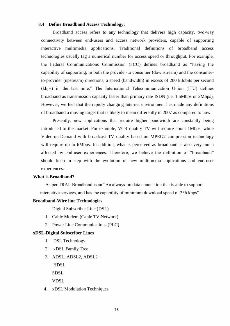
73
8.4 Define Broadband Access Technology:
Broadband access refers to any technology that delivers high capacity, two-way
connectivity between end-users and access network providers, capable of supporting
interactive multimedia applications. Traditional definitions of broadband access
technologies usually tag a numerical number for access speed or throughput. For example,
the Federal Communications Commission (FCC) defines broadband as ―having the
capability of supporting, in both the provider-to consumer (downstream) and the consumer-
to-provider (upstream) directions, a speed (bandwidth) in excess of 200 kilobits per second
(kbps) in the last mile.‖ The International Telecommunication Union (ITU) defines
broadband as transmission capacity faster than primary rate ISDN (i.e. 1.5Mbps or 2Mbps).
However, we feel that the rapidly changing Internet environment has made any definitions
of broadband a moving target that is likely to mean differently in 2007 as compared to now.
Presently, new applications that require higher bandwidth are constantly being
introduced to the market. For example, VCR quality TV will require about 1Mbps, while
Video-on-Demand with broadcast TV quality based on MPEG2 compression technology
will require up to 6Mbps. In addition, what is perceived as broadband is also very much
affected by end-user experiences. Therefore, we believe the definition of ―broadband‖
should keep in step with the evolution of new multimedia applications and end-user
experiences.
What is Broadband?
As per TRAI: Broadband is an ―An always-on data connection that is able to support
interactive services, and has the capability of minimum download speed of 256 kbps‖
Broadband-Wire line Technologies
Digital Subscriber Line (DSL)
1. Cable Modem (Cable TV Network)
2. Power Line Communications (PLC)
xDSL-Digital Subscriber Lines
1. DSL Technology
2. xDSL Family Tree
3. ADSL, ADSL2, ADSL2 +
HDSL
SDSL
VDSL
4. xDSL Modulation Techniques
74
DSL Technology
DSL remains always-on all the time
Customer no longer need to physically dial up to the ISP to ―log in to the
internet‖
On power failure, telephone line is still available like a standard telephone line.
DSL can also be implemented with PPoE (Point to Point Protocol over
Ethernet) that does not support always-on. This is required when authentication
is necessary. PPPoE can be configured in PC or it can be configured in ADSL
modem itself.
xDSL Family Tree
xDSL
Symmetric DSL
Provide identical data rates upstream & downstream
Asymmetric DSL
Provide relatively lower rates upstream but higher rates downstream
Four main variations of xDSL exist:
ADSL-Asymmetrical Digital Sub‘s Line
HDSL-High bit/data rate Digital Sub‘s Line
SDSL-- Symmetric Digital Sub‘s Line
VDSL-Very-high-data-rate Digital Sub‘s Line
ADSL
Asymmetric Digital Subscriber Line
G.DMT / G.992.1 standard
Used for applications which require greater download bandwidth but require
relatively little in opposite direction like Web browsing; File downloads etc.
An ADSL circuit connects an ADSL modem on each end of a twisted pair
telephone line creating three information channels
A high speed downstream channel
A medium speed duplex channel for both upstream & downstream applications
A basic telephone service channel
The basic telephone service channel is split off from the digital modem by
splitter at client site
Allows simultaneous access of the line by the telephone and the computer
In case of power/ADSL failure, data transmission is lost but basic telephone
service will be operational
75
Provides
16-640 kbps upstream
1.5-9 mbps downstream
Can work up to a distance of 3.7 to 5.5 kms
ADSL Lite
Is a form of ADSL
G.Lite / G.992.2 standard
Also known as Universal ADSL or G.Lite
Improves on one of the weakness of regular ADSL i.e. Installation. It has a single
duplex bearer channel.
Does not require splitter to be installed but it does so at the expense of lower data
rates
Supports a maximum of 1.5 Mbps downstream and 512 kbps upstream.
ADSL 2
Second generation of ADSL
G.DMT.bis or G.992.3 standard
Offers a greater data rates of 15 Mb/s downstream and upto 1.5 Mb/s upstream
with a range of 6.4 Kms
Has two power management modes ( L2 mode for power saving at ATU-C by
rapidly entering
and exiting low power mode based on internet traffic over the connection)and L3
mode for
overall power saving at both ATU-C and ATU-R by entering into sleep mode)
that help reduce power consumption Supports seamless adaptation of data rate in
real time to meet the changing line conditions
Fast start up i.e. reduced initialization time from 10 secs to 3 secs.
Data rates can be increased by bonding multiple phone lines ( 2 or more copper
pairs) together.
ADSL 2 +
Second generation of ADSL
G.992.5 standard
76
Doubles the max. Frequency used for downstream data transmission from 1.1
Mhz to 2.2 Mhz.
Offers a greater data rates of 25 Mb/s downstream and up to 1.5 Mb/s upstream.
Can work up to 6.3 Kms with reduced data rates
Has all the other benefits of ADSL 2 like improved power management, seamless
adaptation of data rate in real time to meet the changing line conditions, bonding
of copper pairs for higher data rates etc.
ADSL APPLICATIONS
Internet access ( SOHO)
LAN Access ( Telecommuting)
Distance Learning
Tele-medicine
Broadcast TV
Home shopping
Interactive Games
Movies
SDSL
Symmetric Digital Subscriber Line
Eliminates analog voice capabilities of ADSL in favour of full duplex data
transmission.
Supports data rates up to 3.088 Mb/s ( 1.544 +1.544 Mb/s)
Does not support analog calls
Works up to 3 kms on 0.5 mm dia cable
Affordable alternative to dedicated leased lines
SHDSL-Symmetric High-bit-rate Digital Subscriber
Line is an further improvement over HDSL 2 and SDSL and uses single phone
line
Very-high Data-rate DSL
Also known as BDSL
VDSL connects to the ONU which connect to the central office main fibre
network
Requires one phone line
77
Supports voice & data as well as HDTV
Works between 0.3-1.37 kms depending on speed
8.4.2.2 DSL on copper loop, Optical Fiber Technology, Cable TV network
DSL on copper loop
DSL is one of the main technologies used to provide high speed data
communication services over a local loop (copper loop). Local loop describes the
physical connection between a telephone company Central Office (CO) and a subscriber.
It consists of twisted pair copper wire and dialup call with 4 KHz of bandwidth. It often
has much higher bandwidth; a subscriber close to a CO may be able to handle
frequencies above one MHz
The popularity of DSL technologies grew with the introduction of Asymmetric
Digital Subscriber Line (ADSL) in 1992 as a access technology capable of delivering
Video-On-Demand (VOD) service over telephone networks. ADSL utilizes the same
twisted two-wire facility (called the subscriber loop) as the traditional telephone service.
However, the initial system objective to use ADSL as a technology choice for offering
VOD service was changed to offer high-speed data services in 1994. This attempt
achieved mass-market success and ADSL became the vehicle for high bandwidth
connection to the Internet and as an enabler of broadband services.
DSL on Cable TV network
Cable systems were originally designed to deliver broadcast television signals
efficiently and Coaxial cable has high bandwidth and is less susceptible to
electromagnetic interference than twisted pair. So to ensure that consumers obtain cable
data service with the same TV sets that receive over-the air broadcast TV signals, cable
operators recreate a portion of the over-the-air radio frequency spectrum within a sealed
coaxial cable line. The typical cable frequency spectrum allocation is shown below.
Depending on actual implementations, some cable operators utilize frequencies up to
860MHz.
Upstream Analog Downstream Digital Downstream Unallocated
5-42 MHz 50-550 MHz 550-750 MHz 750-860 MHz
Upstream shared by
return path of all
data services
Analogue Cable TV Digital Cable TV
Downstream for cable modem and
future data services
Normally
not used
78
The 5MHz to 42MHz is usually reserved for upstream communications from
subscribers‘ home back to the head end. The 50MHz to 550MHz band usually supports
analogue transmission, while the 550MHz to 750MHz band usually supports digital TV
transmission as well as other data services such as cable modem, Internet TV and
telephony. Anything above that is normally not used.
Most of cable operators‘ expenses lie in laying a two-way cable network or in
upgrading the existing cable network to carry two-way traffic. Once this has been
accomplished, the cost of adding subscribers is incremental. Deployment issues related to
adding new subscribers on an existing wire line network are minimised.
DSL on Optical Fiber Technology
Optical fibre is seen as the ultimate solution for delivering Interactive Broadband
Multimedia (IBBMM) content to the residential or business consumers. Unlike transition
solutions like Digital Subscriber Line (DSL) and Hybrid Fibre-Coax (HFC) systems,
optical access networks are unlikely to encounter any bandwidth bottleneck. Currently,
optical fibre as a last mile technology is most commonly deployed using opticalbased
Gigabit Ethernet systems or passive optical networks (PONs).
Gigabit Ethernet:- Gigabit Ethernet is a high-speed optical networking
implementation of Ethernet that supports speed of 1Gbps and above. Presently, Ethernet
is the most popular networking technology accounting for over 90% of today‘s Internet
end points. Ethernet is deployed as a ―last feet‖ solution in Local Area Network (LAN)
environment. Gigabit Ethernet is a natural evolution to a higher-speed Ethernet
networking platform. It is easily interfaced with earlier forms of Ethernet, and due to its
higher speed, it is now being used as an access technology for last mile, metropolitan and
even wide area networks. More importantly, it offers cost savings on optoelectronics on a
per Mbps basis compared to Synchronous Optical Network/ Synchronous Digital
Hierarchy, the most popular networking platform for MAN/WAN.
Passive Optical Networks (PONs):- PONs are splitters connecting a few
subscribers onto one shared fibre network by using passive components between the
Optical Network Unit (ONU) and Optical Line Terminating (OLT). The former is to be
installed in or close to customer premises while the later is needed in the local exchange.
PONs eliminate bandwidth bottleneck by bringing the fibre closer to the
building/curb/home. Today, most of these network elements are still expensive to deploy.
Cost-effective ONU and OLT equipment are much needed. Beside price, electrical
powering these network elements and the absence of compelling high-and width
79
applications are prime considerations to the early deployment of PONs in access
network.
8.4.3 Wireless Technology (Wireless access points (APs))
Wireless access points (APs) are a transmitter and receiver (transceiver) device
used to create a wireless LAN (WLAN). APs are typically a separate network device
with a built-in antenna, transmitter, and adapter. APs use the wireless infrastructure
network mode to provide a connection point between WLANs and a wired Ethernet
LAN. APs also typically have several ports allowing a way to expand the network to
support additional clients.
Depending on the size of the network, one or more APs might be required.
Additional APs are used to allow access to more wireless clients and to expand the range
of the wireless network. Each AP is limited by a transmissions range—the distance a
client can be from a AP and still get a useable signal. The actual distance depends on the
wireless standard being used and the obstructions and environmental conditions between
the client and the AP. Saying that an AP is used to extend a wired LAN to wireless
clients doesn‘t give you the complete picture. A wireless AP today can provide different
services in addition to just an access point. Today, the APs might provide many ports that
can be used to easily increase the size of the network. Systems can be added and removed
from the network with no affect on other systems on the network. Also, many APs
provide firewall capabilities and DHCP service. When they are hooked up, they will
provide client systems with a private IP address and then prevent Internet traffic from
accessing client systems. So in effect, the AP is a switch, a DHCP Server, router, and a
firewall.
APs come in all different shapes and sizes. Many are cheaper and designed
strictly for home or small office use. Such APs have low powered antennas and limited
expansion ports. Higher end APs used for commercial purposes have very high powered
antennas enabling them to extend the range that the wireless signal can travel.
Transceivers (Media Converters)
The term transceiver does describe a separate network device, but it can also be
technology built and embedded in devices such as network cards and modems. In a
network environment, a transceiver gets its name from being both a transmitter and a
receiver of signals—thus the name transceivers. Technically, on a LAN, the transceiver is
responsible for placing signals onto the network media and also detecting incoming
signals travelling through the same wire. Given the description of the function of a
transceiver, it makes sense that that technology would be found with network cards.
80
Although transceivers are found in network cards, they can be external devices as well.
As far as networking is concerned, transceivers can ship as a module or chip type. Chip
transceivers are small and are inserted into a system board or wired directly on a circuit
board. Module transceivers are external to the network and are installed and function
similarly to other computer peripherals, or they can function as standalone devices. There
are many types of transceivers—RF transceivers, fiber optic transceivers, Ethernet
transceivers, wireless (WAP) transceivers, and more. Though each of these media types
is different, the function of the transceiver remains the same. Each type of the transceiver
used has different characteristics, such as the number of ports available to connect to the
network and whether full-duplex communication is supported.
Listed with transceivers in the Comp TIA objectives are media converters. Media
converters are a technology that allows administrators to interconnect different media
types—for example, twisted pair, fiber, and Thin or thick coax—within an existing
network. Using a media converter, it is possible to connect newer 100Mbps, Gigabit
Ethernet, or ATM equipment to existing networks such as 10BASE-T or 100BASE-T.
They can also be used in pairs to insert a fiber segment into copper networks to increase
cabling distances and enhance immunity to electromagnetic interference (EMI).
Firewalls
A firewall is a networking device, either hardware or software based, that controls
access to your organization‘s network. This controlled access is designed to protect data
and resources from an outside threat. To do this, firewalls are typically placed at
entry/exit points of a network—for example, placing a firewall between an internal
network and the Internet. Once there, it can control access in and out of that point.
Although firewalls typically protect internal networks from public networks, they are
also used to control access between specific network segments within a network—for
example, placing a firewall between the Accounts and the Sales departments. As
mentioned, firewalls can be implemented through software or through a dedicated
hardware device. Organizations implement software firewalls through network operating
systems (NOS) such as Linux/UNIX, Windows servers, and Mac OS servers. The
firewall is configured on the server to allow or permit certain types of network traffic. In
small offices and for regular home use, a firewall is commonly installed on the local
system and configured to control traffic. Many third-party firewalls are available.
Hardware firewalls are used in networks of all sizes today. Hardware firewalls are often
dedicated network devices that can be implemented with very little configuration and
81
protect all systems behind the firewall from outside sources. Hardware firewalls are
readily available and often combined with other devices today. For example, many
broadband routers and wireless access points have firewall functionality built in. In such
case, the router or WAP might have a number of ports available to plug systems in to.
8.4.3.1 Bluetooth Technology
Bluetooth is a wireless LAN technology designed to connect devices of different
functions such as telephones, notebooks, computers (desktop and laptop), cameras,
printers, and even coffee makers when they are at a short distance from each other. A
Bluetooth LAN is an ad hoc network, which means that the network is formed
spontaneously; the devices, sometimes called gadgets, find each other and make a
network called a piconet. A Bluetooth LAN can even be connected to the Internet if one
of the gadgets has this capability. A Bluetooth LAN, by nature, cannot be large. If there
are many gadgets that try to connect, there is chaos.
Bluetooth technology has several applications. Peripheral devices such as a
wireless mouse or keyboard can communicate with the computer through this
technology. Monitoring devices can communicate with sensor devices in a small health
care center. Home security devices can use this technology to connect different sensors to
the main security controller. Conference attendees can synchronize their laptop
computers at a conference.
Bluetooth was originally started as a project by the Ericsson Company. It is
named for Harald Blaatand, the king of Denmark (940-981) who united Denmark and
Norway. Blaatand translates to Bluetooth in English.
Today, Bluetooth technology is the implementation of a protocol defined by the
IEEE 802.15 standard. The standard defines a wireless personal-area network (PAN)
operable in an area the size of a room or a hall.
Architecture
Bluetooth defines two types of networks: piconet and scatternet.
Piconets
A Bluetooth network is called a piconet, or a small net. A piconet can have up to
eight stations, one of which is called the primary(Master); the rest are called secondaries
(Slave). All the secondary stations synchronize their clocks and hopping sequence with
the primary. Note that a piconet can have only one primary station. The communication
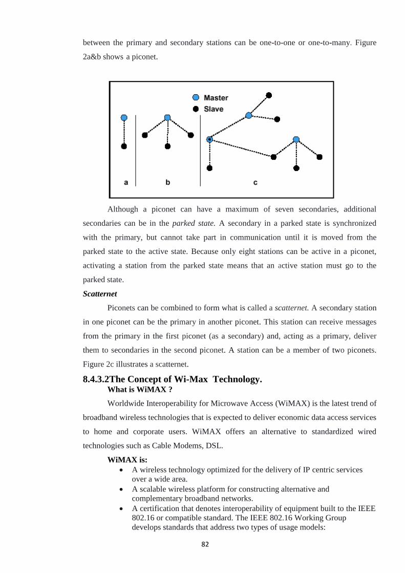
82
between the primary and secondary stations can be one-to-one or one-to-many. Figure
2a&b shows a piconet.
Although a piconet can have a maximum of seven secondaries, additional
secondaries can be in the parked state. A secondary in a parked state is synchronized
with the primary, but cannot take part in communication until it is moved from the
parked state to the active state. Because only eight stations can be active in a piconet,
activating a station from the parked state means that an active station must go to the
parked state.
Scatternet
Piconets can be combined to form what is called a scatternet. A secondary station
in one piconet can be the primary in another piconet. This station can receive messages
from the primary in the first piconet (as a secondary) and, acting as a primary, deliver
them to secondaries in the second piconet. A station can be a member of two piconets.
Figure 2c illustrates a scatternet.
8.4.3.2The Concept of Wi-Max Technology. What is WiMAX ?
Worldwide Interoperability for Microwave Access (WiMAX) is the latest trend of
broadband wireless technologies that is expected to deliver economic data access services
to home and corporate users. WiMAX offers an alternative to standardized wired
technologies such as Cable Modems, DSL.
WiMAX is:
A wireless technology optimized for the delivery of IP centric services
over a wide area.
A scalable wireless platform for constructing alternative and
complementary broadband networks.
A certification that denotes interoperability of equipment built to the IEEE
802.16 or compatible standard. The IEEE 802.16 Working Group
develops standards that address two types of usage models:
83
1. A fixed usage model (IEEE 802.16-2004).
2. A portable usage model (IEEE 802.16e).
What is 802.16?
IEEE 802.16 is a series of wireless broadband standard which is commercialized
under the name WiMAX. The 802.16a standard for 2-11 GHz is a WMAN
technology that provides broadband wireless connectivity to fixed and portable
devices.
It can be used to connect 802.11 hotspots to the Internet and as a wireless
alternative to cable and DSL for last-mile broadband access
WiMax Speed and Range
Long range and high bitrates are the main characteristics of WiMAX network
access. However, both these characteristics are inversely proportional, i.e., for long
ranges, WiMAX provides lower bitrates. Inversely, WiMAX provides access at high
bitrates for users located in close range. WiMAX can stretch up to a maximum range of
50 km (31 miles approx.). It can provide access at a maximum bitrate of 75 Mbps and a
minimum of 1Mbps. WiMAX could potentially be deployed in a variety of spectrum
bands: 2.3GHz, 2.5GHz, 3.5GHz, and 5.8GHz.
WiMAX is also expected to provide broadband connectivity to mobile devices,
however it would not be as fast as in case of fixed applications. WiMAX can support
voice, video, as well as Internet data.
Why WiMax?
WiMAX can satisfy a variety of access needs. Potential applications include
extending broadband capabilities to bring them closer to subscribers, filling gaps in
cable, DSL and T1 services, WiFi and cellular backhaul, providing last-mile access, and
giving service providers another cost-effective option for supporting broadband services.
WiMAX can support very high bandwidth where large spectrum deployments
(i.e. >10 MHz) are desired using existing infrastructure. It keeps costs down while
delivering the required bandwidth to support a full range of high-value multimedia
services.
WiMAX can help service providers meet increasing customer demands without
discarding their existing infrastructure. WiMAX has the ability to seamlessly interoperate
across various network types.
WiMAX can provide wide area coverage and QoS capabilities for applications
ranging from real-time delay-sensitive Voice over IP (VoIP) to real-time streaming video
84
and non-real-time downloads. WiMAX ensures the subscribers get the performance they
expect for all types of communications.
WiMAX, which is an IP-based wireless broadband technology, can be integrated
into both wide-area third-generation (3G) mobile and wireless and wired networks.
Ultimately, WiMAX is intended to serve as the next step in the evolution of 3G
mobile phones, via a potential combination of WiMAX and CDMA standards called 4G.
What is Wi-Fi ?
Wi-Fi stands for Wireless Fidelity. Wi-Fi is based on the IEEE 802.11 family of
standards and is primarily a local area networking (LAN) technology designed to provide
in-building broadband coverage.
Current Wi-Fi systems based on IEEE 802.11a/g support a peak physical-layer
data rate of 54Mbps and typically provide indoor coverage over a distance of 100 feet.
Wi-Fi has become the defacto standard for last feet broadband connectivity in
homes, offices, and public hotspot locations. systems can typically provide a coverage
range of only about 1,000 feet from the access point.
Wi-Fi offers remarkably higher peak data rates than do 3G systems, primarily
since it operates over a larger 20MHz bandwidth, but Wi-Fi systems are not designed to
support high-speed mobility.
One significant advantage of Wi-Fi over WiMAX and 3G is the wide availability
of terminal devices. A vast majority of laptops shipped today have a built-in Wi-Fi
interface. Wi-Fi interfaces are now also being built into a variety of devices, including
personal data assistants (PDAs), cordless phones, cellular phones, cameras, and media
players.
Wi-Fi is Half Duplex:
All Wi-Fi networks are contention-based TDD systems, where the access point
and the mobile stations all vie for use of the same channel. Because of the shared media
operation, all Wi-Fi networks are half duplex.
There are equipment vendors who market Wi-Fi mesh configurations, but those
implementations incorporate technologies that are not defined in the standards.
Channel Bandwidth:
The WiFi standards define a fixed channel bandwidth of 25 MHz for 802.11b and
20 MHz for either 802.11a or g networks.
85
Wi-Fi Working Concepts Radio Signals:
Radio Signals are the keys, which make WiFi networking possible. These radio
signals transmitted from Wi-Fi antennas are picked up by WiFi receivers, such as
computers and cell phones that are equipped with WiFi cards. Whenever, a computer
receives any of the signals within the range of a WiFi network, which is usually 300 -
500 feet for antennas, the WiFi card will read the signals and thus create an internet
connection between the user and the network without the use of a cord.
Access points which consist of antennas and routers are the main source which
transmit and receive radio waves.
Antennas work stronger and have a longer radio transmission with a radius of
300-500 feet which are used in public areas while the weaker yet effective router is more
suitable for homes with a radio transmission of 100-150 feet.
Wi-Fi IEEE Standards
The 802.11 standard is defined through several specifications of WLANs. It
defines an over-the-air interface between a wireless client and a base station or between
two wireless clients.
There are several specifications in the 802.11 family:
802.11: This pertains to wireless LANs and provides 1- or 2-Mbps transmission
in the 2.4-GHz band using either frequency-hopping spread spectrum (FHSS) or direct-
sequence spread spectrum (DSSS).
802.11a: This is an extension to 802.11, that pertains to wireless LANs and goes
as fast as 54 Mbps in the 5-GHz band. 802.11a employs the orthogonal frequency
division multiplexing (OFDM) encoding scheme as opposed to either FHSS or DSSS.
802.11b: The 802.11 high rate Wi-Fi is an extension to 802.11 that pertains to
wireless LANs and yields a connection as fast as 11 Mbps transmission (with a fallback
to 5.5, 2, and 1 Mbps depending on strength of signal) in the 2.4-GHz band. The 802.11b
specification uses only DSSS. Note that 802.11b was actually an amendment to the
original 802.11 standard added in 1999 to permit wireless functionality to be analogous
to hard-wired Ethernet connections.
802.11g: This pertains to wireless LANs and provides 20+ Mbps in the 2.4-GHz
band.
Here is the technical comparison between the Wi-Fi & Wi-Max standards
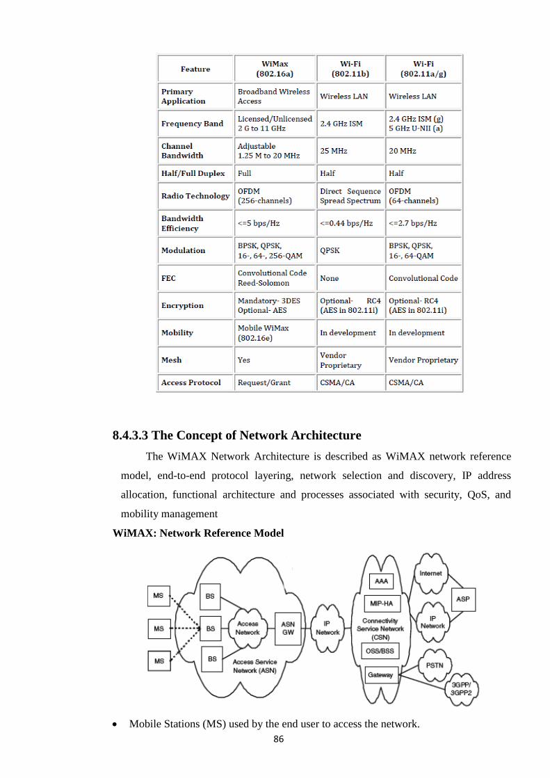
86
8.4.3.3 The Concept of Network Architecture
The WiMAX Network Architecture is described as WiMAX network reference
model, end-to-end protocol layering, network selection and discovery, IP address
allocation, functional architecture and processes associated with security, QoS, and
mobility management
WiMAX: Network Reference Model
Mobile Stations (MS) used by the end user to access the network.
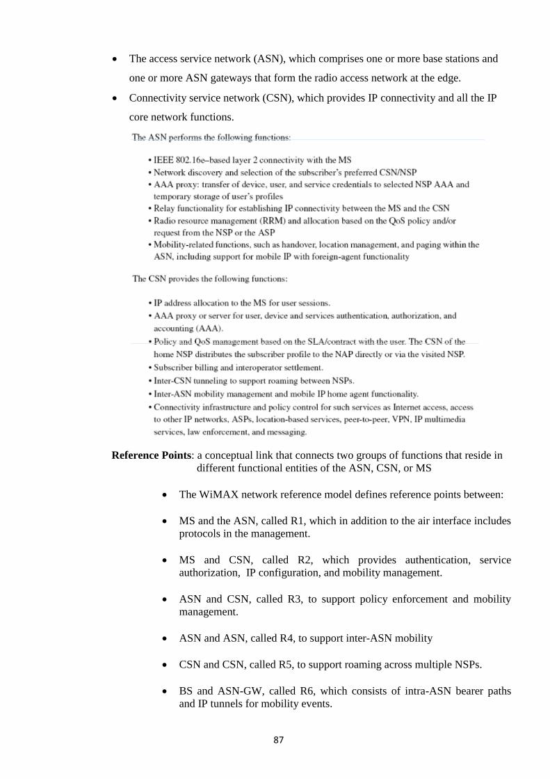
87
The access service network (ASN), which comprises one or more base stations and
one or more ASN gateways that form the radio access network at the edge.
Connectivity service network (CSN), which provides IP connectivity and all the IP
core network functions.
Reference Points: a conceptual link that connects two groups of functions that reside in
different functional entities of the ASN, CSN, or MS
The WiMAX network reference model defines reference points between:
MS and the ASN, called R1, which in addition to the air interface includes
protocols in the management.
MS and CSN, called R2, which provides authentication, service
authorization, IP configuration, and mobility management.
ASN and CSN, called R3, to support policy enforcement and mobility
management.
ASN and ASN, called R4, to support inter-ASN mobility
CSN and CSN, called R5, to support roaming across multiple NSPs.
BS and ASN-GW, called R6, which consists of intra-ASN bearer paths
and IP tunnels for mobility events.
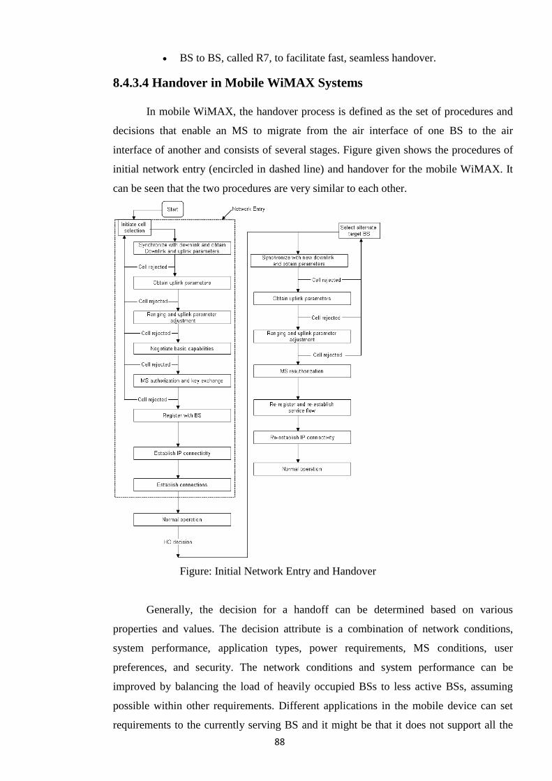
88
BS to BS, called R7, to facilitate fast, seamless handover.
8.4.3.4 Handover in Mobile WiMAX Systems
In mobile WiMAX, the handover process is defined as the set of procedures and
decisions that enable an MS to migrate from the air interface of one BS to the air
interface of another and consists of several stages. Figure given shows the procedures of
initial network entry (encircled in dashed line) and handover for the mobile WiMAX. It
can be seen that the two procedures are very similar to each other.
Figure: Initial Network Entry and Handover
Generally, the decision for a handoff can be determined based on various
properties and values. The decision attribute is a combination of network conditions,
system performance, application types, power requirements, MS conditions, user
preferences, and security. The network conditions and system performance can be
improved by balancing the load of heavily occupied BSs to less active BSs, assuming
possible within other requirements. Different applications in the mobile device can set
requirements to the currently serving BS and it might be that it does not support all the
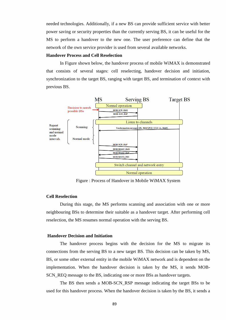
89
needed technologies. Additionally, if a new BS can provide sufficient service with better
power saving or security properties than the currently serving BS, it can be useful for the
MS to perform a handover to the new one. The user preference can define that the
network of the own service provider is used from several available networks.
Handover Process and Cell Reselection
In Figure shown below, the handover process of mobile WiMAX is demonstrated
that consists of several stages: cell reselecting, handover decision and initiation,
synchronization to the target BS, ranging with target BS, and termination of context with
previous BS.
Figure : Process of Handover in Mobile WiMAX System
Cell Reselection
During this stage, the MS performs scanning and association with one or more
neighbouring BSs to determine their suitable as a handover target. After performing cell
reselection, the MS resumes normal operation with the serving BS.
Handover Decision and Initiation
The handover process begins with the decision for the MS to migrate its
connections from the serving BS to a new target BS. This decision can be taken by MS,
BS, or some other external entity in the mobile WiMAX network and is dependent on the
implementation. When the handover decision is taken by the MS, it sends MOB-
SCN_REQ message to the BS, indicating one or more BSs as handover targets.
The BS then sends a MOB-SCN_RSP message indicating the target BSs to be
used for this handover process. When the handover decision is taken by the BS, it sends a
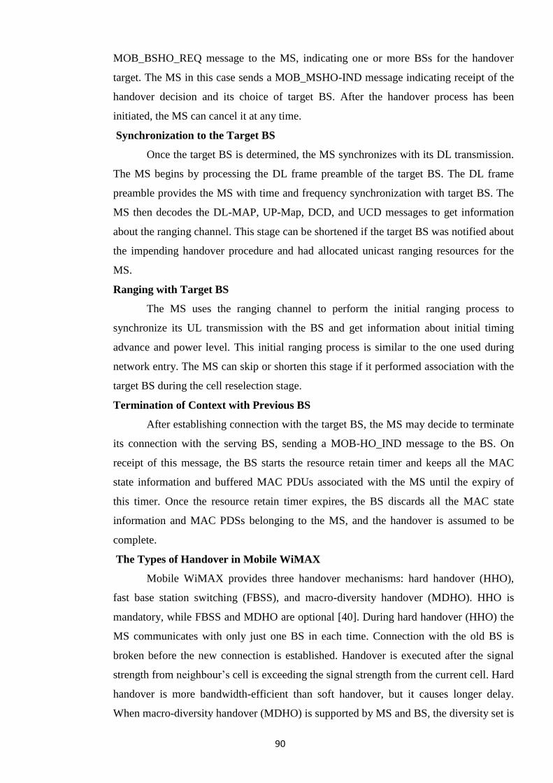
90
MOB_BSHO_REQ message to the MS, indicating one or more BSs for the handover
target. The MS in this case sends a MOB_MSHO-IND message indicating receipt of the
handover decision and its choice of target BS. After the handover process has been
initiated, the MS can cancel it at any time.
Synchronization to the Target BS
Once the target BS is determined, the MS synchronizes with its DL transmission.
The MS begins by processing the DL frame preamble of the target BS. The DL frame
preamble provides the MS with time and frequency synchronization with target BS. The
MS then decodes the DL-MAP, UP-Map, DCD, and UCD messages to get information
about the ranging channel. This stage can be shortened if the target BS was notified about
the impending handover procedure and had allocated unicast ranging resources for the
MS.
Ranging with Target BS
The MS uses the ranging channel to perform the initial ranging process to
synchronize its UL transmission with the BS and get information about initial timing
advance and power level. This initial ranging process is similar to the one used during
network entry. The MS can skip or shorten this stage if it performed association with the
target BS during the cell reselection stage.
Termination of Context with Previous BS
After establishing connection with the target BS, the MS may decide to terminate
its connection with the serving BS, sending a MOB-HO_IND message to the BS. On
receipt of this message, the BS starts the resource retain timer and keeps all the MAC
state information and buffered MAC PDUs associated with the MS until the expiry of
this timer. Once the resource retain timer expires, the BS discards all the MAC state
information and MAC PDSs belonging to the MS, and the handover is assumed to be
complete.
The Types of Handover in Mobile WiMAX
Mobile WiMAX provides three handover mechanisms: hard handover (HHO),
fast base station switching (FBSS), and macro-diversity handover (MDHO). HHO is
mandatory, while FBSS and MDHO are optional [40]. During hard handover (HHO) the
MS communicates with only just one BS in each time. Connection with the old BS is
broken before the new connection is established. Handover is executed after the signal
strength from neighbour‘s cell is exceeding the signal strength from the current cell. Hard
handover is more bandwidth-efficient than soft handover, but it causes longer delay.
When macro-diversity handover (MDHO) is supported by MS and BS, the diversity set is
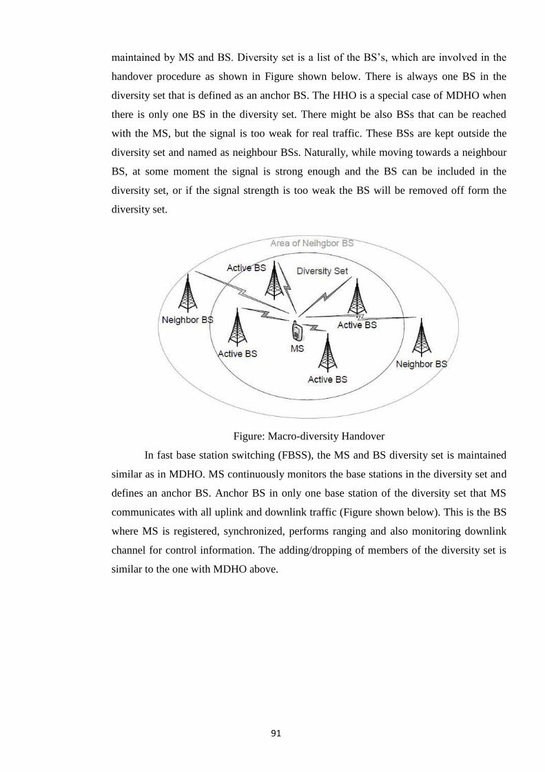
91
maintained by MS and BS. Diversity set is a list of the BS‘s, which are involved in the
handover procedure as shown in Figure shown below. There is always one BS in the
diversity set that is defined as an anchor BS. The HHO is a special case of MDHO when
there is only one BS in the diversity set. There might be also BSs that can be reached
with the MS, but the signal is too weak for real traffic. These BSs are kept outside the
diversity set and named as neighbour BSs. Naturally, while moving towards a neighbour
BS, at some moment the signal is strong enough and the BS can be included in the
diversity set, or if the signal strength is too weak the BS will be removed off form the
diversity set.
Figure: Macro-diversity Handover
In fast base station switching (FBSS), the MS and BS diversity set is maintained
similar as in MDHO. MS continuously monitors the base stations in the diversity set and
defines an anchor BS. Anchor BS in only one base station of the diversity set that MS
communicates with all uplink and downlink traffic (Figure shown below). This is the BS
where MS is registered, synchronized, performs ranging and also monitoring downlink
channel for control information. The adding/dropping of members of the diversity set is
similar to the one with MDHO above.
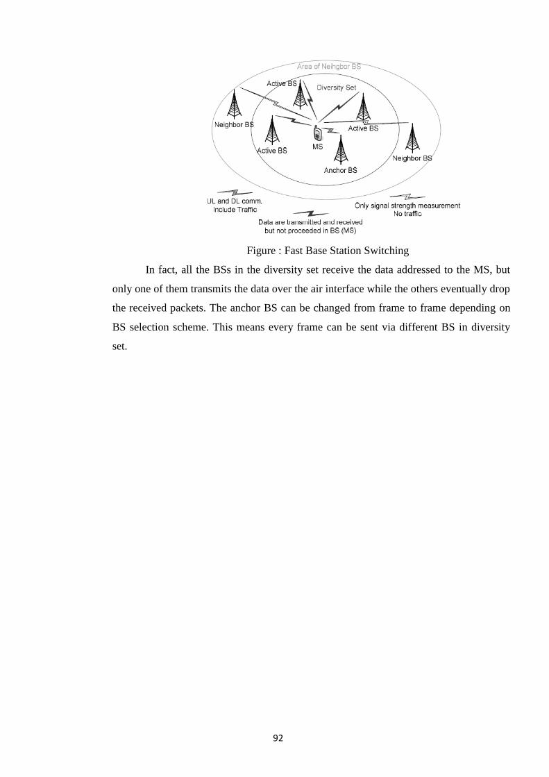
92
Figure : Fast Base Station Switching
In fact, all the BSs in the diversity set receive the data addressed to the MS, but
only one of them transmits the data over the air interface while the others eventually drop
the received packets. The anchor BS can be changed from frame to frame depending on
BS selection scheme. This means every frame can be sent via different BS in diversity
set.
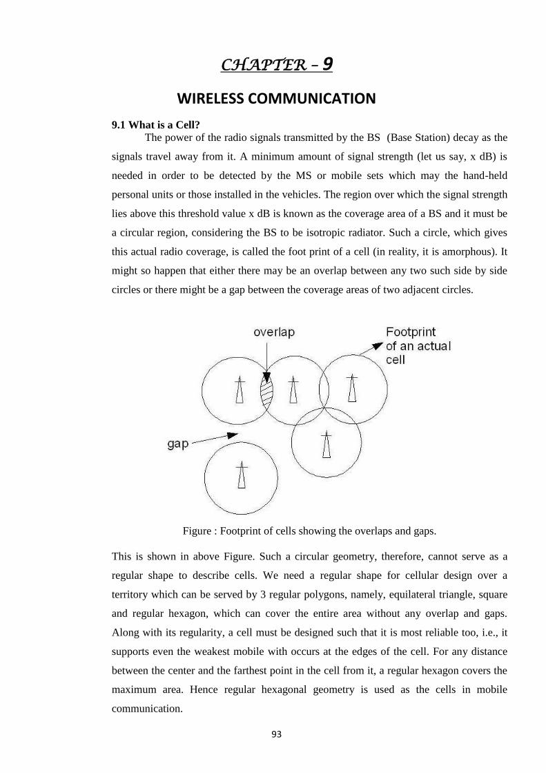
93
CHAPTER – 9
WIRELESS COMMUNICATION
9.1 What is a Cell?
The power of the radio signals transmitted by the BS (Base Station) decay as the
signals travel away from it. A minimum amount of signal strength (let us say, x dB) is
needed in order to be detected by the MS or mobile sets which may the hand-held
personal units or those installed in the vehicles. The region over which the signal strength
lies above this threshold value x dB is known as the coverage area of a BS and it must be
a circular region, considering the BS to be isotropic radiator. Such a circle, which gives
this actual radio coverage, is called the foot print of a cell (in reality, it is amorphous). It
might so happen that either there may be an overlap between any two such side by side
circles or there might be a gap between the coverage areas of two adjacent circles.
Figure : Footprint of cells showing the overlaps and gaps.
This is shown in above Figure. Such a circular geometry, therefore, cannot serve as a
regular shape to describe cells. We need a regular shape for cellular design over a
territory which can be served by 3 regular polygons, namely, equilateral triangle, square
and regular hexagon, which can cover the entire area without any overlap and gaps.
Along with its regularity, a cell must be designed such that it is most reliable too, i.e., it
supports even the weakest mobile with occurs at the edges of the cell. For any distance
between the center and the farthest point in the cell from it, a regular hexagon covers the
maximum area. Hence regular hexagonal geometry is used as the cells in mobile
communication.
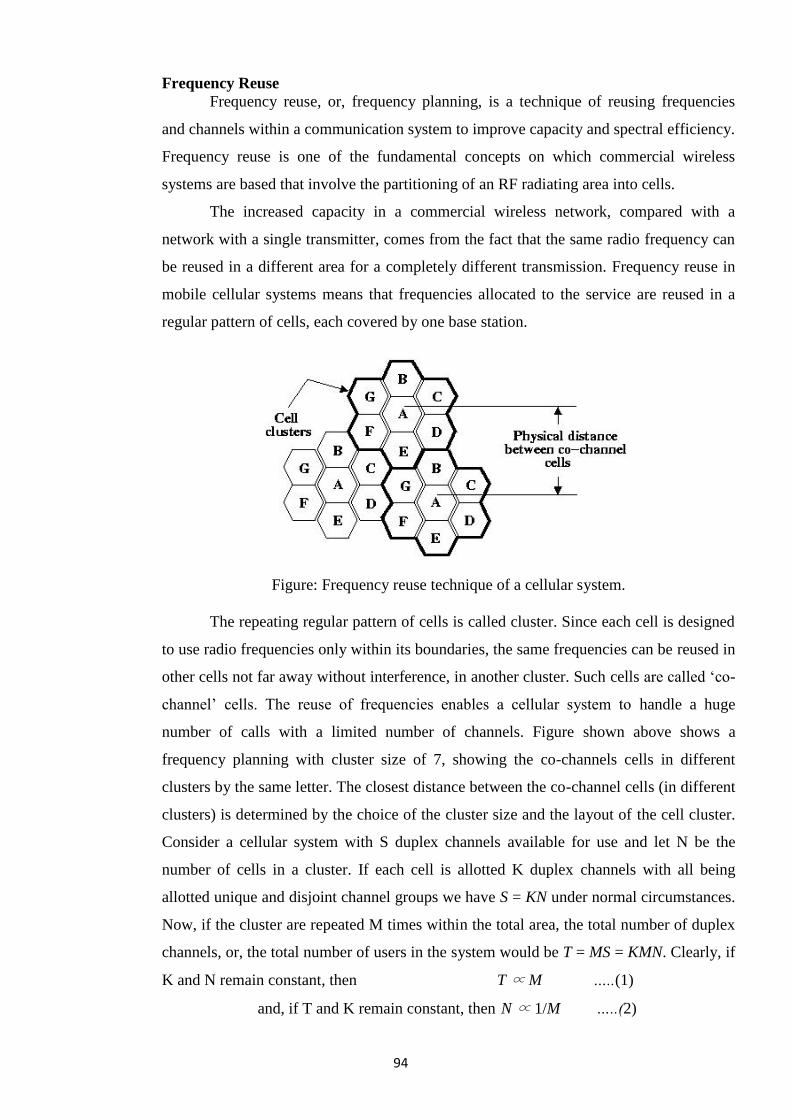
94
Frequency Reuse
Frequency reuse, or, frequency planning, is a technique of reusing frequencies
and channels within a communication system to improve capacity and spectral efficiency.
Frequency reuse is one of the fundamental concepts on which commercial wireless
systems are based that involve the partitioning of an RF radiating area into cells.
The increased capacity in a commercial wireless network, compared with a
network with a single transmitter, comes from the fact that the same radio frequency can
be reused in a different area for a completely different transmission. Frequency reuse in
mobile cellular systems means that frequencies allocated to the service are reused in a
regular pattern of cells, each covered by one base station.
Figure: Frequency reuse technique of a cellular system.
The repeating regular pattern of cells is called cluster. Since each cell is designed
to use radio frequencies only within its boundaries, the same frequencies can be reused in
other cells not far away without interference, in another cluster. Such cells are called ‗co-
channel‘ cells. The reuse of frequencies enables a cellular system to handle a huge
number of calls with a limited number of channels. Figure shown above shows a
frequency planning with cluster size of 7, showing the co-channels cells in different
clusters by the same letter. The closest distance between the co-channel cells (in different
clusters) is determined by the choice of the cluster size and the layout of the cell cluster.
Consider a cellular system with S duplex channels available for use and let N be the
number of cells in a cluster. If each cell is allotted K duplex channels with all being
allotted unique and disjoint channel groups we have S = KN under normal circumstances.
Now, if the cluster are repeated M times within the total area, the total number of duplex
channels, or, the total number of users in the system would be T = MS = KMN. Clearly, if
K and N remain constant, then T ∝ M …..(1)
and, if T and K remain constant, then N ∝ 1/M …..(2)
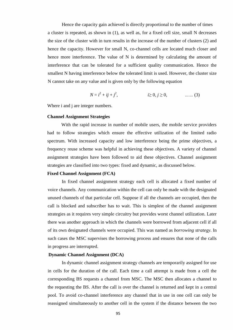
95
Hence the capacity gain achieved is directly proportional to the number of times
a cluster is repeated, as shown in (1), as well as, for a fixed cell size, small N decreases
the size of the cluster with in turn results in the increase of the number of clusters (2) and
hence the capacity. However for small N, co-channel cells are located much closer and
hence more interference. The value of N is determined by calculating the amount of
interference that can be tolerated for a sufficient quality communication. Hence the
smallest N having interference below the tolerated limit is used. However, the cluster size
N cannot take on any value and is given only by the following equation
N = i2 + ij + j
2, i≥ 0, j ≥ 0, …… (3)
Where i and j are integer numbers.
Channel Assignment Strategies
With the rapid increase in number of mobile users, the mobile service providers
had to follow strategies which ensure the effective utilization of the limited radio
spectrum. With increased capacity and low interference being the prime objectives, a
frequency reuse scheme was helpful in achieving these objectives. A variety of channel
assignment strategies have been followed to aid these objectives. Channel assignment
strategies are classified into two types: fixed and dynamic, as discussed below.
Fixed Channel Assignment (FCA)
In fixed channel assignment strategy each cell is allocated a fixed number of
voice channels. Any communication within the cell can only be made with the designated
unused channels of that particular cell. Suppose if all the channels are occupied, then the
call is blocked and subscriber has to wait. This is simplest of the channel assignment
strategies as it requires very simple circuitry but provides worst channel utilization. Later
there was another approach in which the channels were borrowed from adjacent cell if all
of its own designated channels were occupied. This was named as borrowing strategy. In
such cases the MSC supervises the borrowing process and ensures that none of the calls
in progress are interrupted.
Dynamic Channel Assignment (DCA)
In dynamic channel assignment strategy channels are temporarily assigned for use
in cells for the duration of the call. Each time a call attempt is made from a cell the
corresponding BS requests a channel from MSC. The MSC then allocates a channel to
the requesting the BS. After the call is over the channel is returned and kept in a central
pool. To avoid co-channel interference any channel that in use in one cell can only be
reassigned simultaneously to another cell in the system if the distance between the two
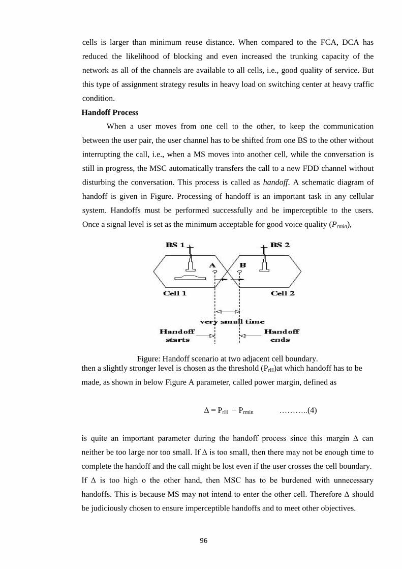
96
cells is larger than minimum reuse distance. When compared to the FCA, DCA has
reduced the likelihood of blocking and even increased the trunking capacity of the
network as all of the channels are available to all cells, i.e., good quality of service. But
this type of assignment strategy results in heavy load on switching center at heavy traffic
condition.
Handoff Process
When a user moves from one cell to the other, to keep the communication
between the user pair, the user channel has to be shifted from one BS to the other without
interrupting the call, i.e., when a MS moves into another cell, while the conversation is
still in progress, the MSC automatically transfers the call to a new FDD channel without
disturbing the conversation. This process is called as handoff. A schematic diagram of
handoff is given in Figure. Processing of handoff is an important task in any cellular
system. Handoffs must be performed successfully and be imperceptible to the users.
Once a signal level is set as the minimum acceptable for good voice quality (Prmin),
Figure: Handoff scenario at two adjacent cell boundary.
then a slightly stronger level is chosen as the threshold (PrH)at which handoff has to be
made, as shown in below Figure A parameter, called power margin, defined as
Δ = PrH − Prmin ………..(4)
is quite an important parameter during the handoff process since this margin Δ can
neither be too large nor too small. If Δ is too small, then there may not be enough time to
complete the handoff and the call might be lost even if the user crosses the cell boundary.
If Δ is too high o the other hand, then MSC has to be burdened with unnecessary
handoffs. This is because MS may not intend to enter the other cell. Therefore Δ should
be judiciously chosen to ensure imperceptible handoffs and to meet other objectives.
97
Factors Influencing Handoffs
The following factors influence the entire handoff process:
(a) Transmitted power: as we know that the transmission power is different for different
cells, the handoff threshold or the power margin varies from cell to cell.
(b) Received power: the received power mostly depends on the Line of Sight (LoS) path
between the user and the BS. Especially when the user is on the boundary of the two
cells,
Figure: Handoff process associated with power levels, when the user is going from i-th
cell to j-th cell.
the LoS path plays a critical role in handoffs and therefore the power margin Δ depends
on the minimum received power value from cell to cell.
(c) Area and shape of the cell: Apart from the power levels, the cell structure also a plays
an important role in the handoff process.
(d) Mobility of users: The number of mobile users entering or going out of a particular
cell also fixes the handoff strategy of a cell.
Interference & System Capacity
Susceptibility and interference problems associated with mobile communications
equipment are because of the problem of time congestion within the electromagnetic
spectrum. It is the limiting factor in the performance of cellular systems. This
interference can occur from clash with another mobile in the same cell or because of a
call in the adjacent cell. There can be interference between the base stations operating at
same frequency band or any other non-cellular system‘s energy leaking inadvertently into
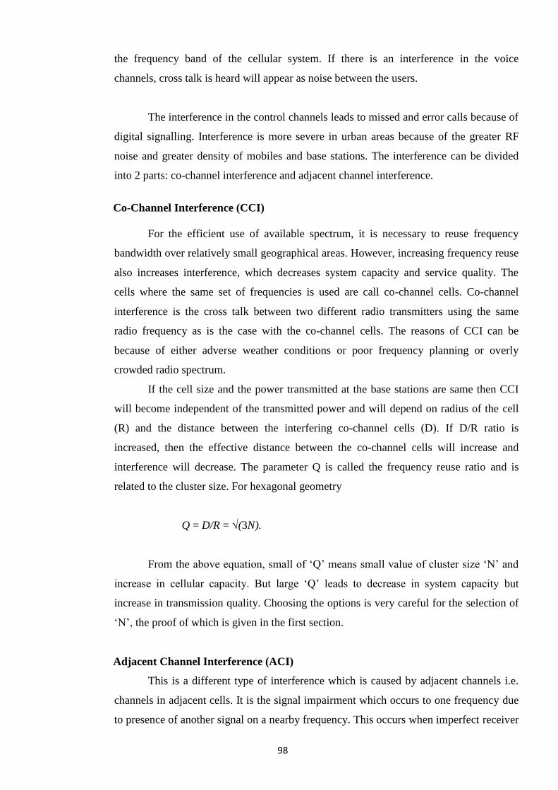
98
the frequency band of the cellular system. If there is an interference in the voice
channels, cross talk is heard will appear as noise between the users.
The interference in the control channels leads to missed and error calls because of
digital signalling. Interference is more severe in urban areas because of the greater RF
noise and greater density of mobiles and base stations. The interference can be divided
into 2 parts: co-channel interference and adjacent channel interference.
Co-Channel Interference (CCI)
For the efficient use of available spectrum, it is necessary to reuse frequency
bandwidth over relatively small geographical areas. However, increasing frequency reuse
also increases interference, which decreases system capacity and service quality. The
cells where the same set of frequencies is used are call co-channel cells. Co-channel
interference is the cross talk between two different radio transmitters using the same
radio frequency as is the case with the co-channel cells. The reasons of CCI can be
because of either adverse weather conditions or poor frequency planning or overly
crowded radio spectrum.
If the cell size and the power transmitted at the base stations are same then CCI
will become independent of the transmitted power and will depend on radius of the cell
(R) and the distance between the interfering co-channel cells (D). If D/R ratio is
increased, then the effective distance between the co-channel cells will increase and
interference will decrease. The parameter Q is called the frequency reuse ratio and is
related to the cluster size. For hexagonal geometry
Q = D/R = √(3N).
From the above equation, small of ‗Q‘ means small value of cluster size ‗N‘ and
increase in cellular capacity. But large ‗Q‘ leads to decrease in system capacity but
increase in transmission quality. Choosing the options is very careful for the selection of
‗N‘, the proof of which is given in the first section.
Adjacent Channel Interference (ACI)
This is a different type of interference which is caused by adjacent channels i.e.
channels in adjacent cells. It is the signal impairment which occurs to one frequency due
to presence of another signal on a nearby frequency. This occurs when imperfect receiver
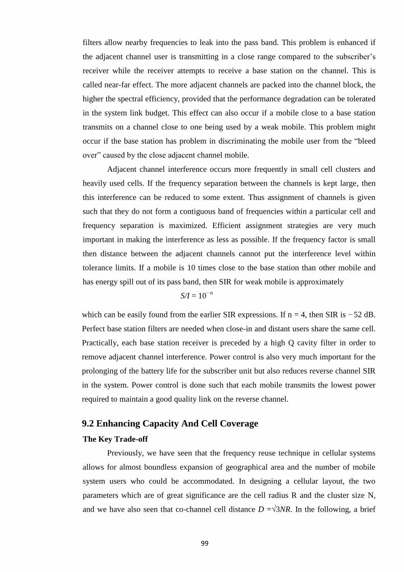
99
filters allow nearby frequencies to leak into the pass band. This problem is enhanced if
the adjacent channel user is transmitting in a close range compared to the subscriber‘s
receiver while the receiver attempts to receive a base station on the channel. This is
called near-far effect. The more adjacent channels are packed into the channel block, the
higher the spectral efficiency, provided that the performance degradation can be tolerated
in the system link budget. This effect can also occur if a mobile close to a base station
transmits on a channel close to one being used by a weak mobile. This problem might
occur if the base station has problem in discriminating the mobile user from the ―bleed
over‖ caused by the close adjacent channel mobile.
Adjacent channel interference occurs more frequently in small cell clusters and
heavily used cells. If the frequency separation between the channels is kept large, then
this interference can be reduced to some extent. Thus assignment of channels is given
such that they do not form a contiguous band of frequencies within a particular cell and
frequency separation is maximized. Efficient assignment strategies are very much
important in making the interference as less as possible. If the frequency factor is small
then distance between the adjacent channels cannot put the interference level within
tolerance limits. If a mobile is 10 times close to the base station than other mobile and
has energy spill out of its pass band, then SIR for weak mobile is approximately
S/I = 10−n
which can be easily found from the earlier SIR expressions. If n = 4, then SIR is −52 dB.
Perfect base station filters are needed when close-in and distant users share the same cell.
Practically, each base station receiver is preceded by a high Q cavity filter in order to
remove adjacent channel interference. Power control is also very much important for the
prolonging of the battery life for the subscriber unit but also reduces reverse channel SIR
in the system. Power control is done such that each mobile transmits the lowest power
required to maintain a good quality link on the reverse channel.
9.2 Enhancing Capacity And Cell Coverage
The Key Trade-off
Previously, we have seen that the frequency reuse technique in cellular systems
allows for almost boundless expansion of geographical area and the number of mobile
system users who could be accommodated. In designing a cellular layout, the two
parameters which are of great significance are the cell radius R and the cluster size N,
and we have also seen that co-channel cell distance D =√3NR. In the following, a brief
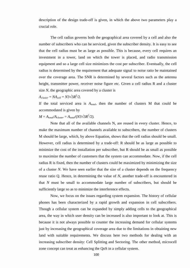
100
description of the design trade-off is given, in which the above two parameters play a
crucial role.
The cell radius governs both the geographical area covered by a cell and also the
number of subscribers who can be serviced, given the subscriber density. It is easy to see
that the cell radius must be as large as possible. This is because, every cell requires an
investment in a tower, land on which the tower is placed, and radio transmission
equipment and so a large cell size minimizes the cost per subscriber. Eventually, the cell
radius is determined by the requirement that adequate signal to noise ratio be maintained
over the coverage area. The SNR is determined by several factors such as the antenna
height, transmitter power, receiver noise figure etc. Given a cell radius R and a cluster
size N, the geographic area covered by a cluster is
Acluster = NAcell = N3√3R2/2.
If the total serviced area is Atotal, then the number of clusters M that could be
accommodated is given by
M = Atotal/Acluster = Atotal/(N3√3R2/2).
Note that all of the available channels N, are reused in every cluster. Hence, to
make the maximum number of channels available to subscribers, the number of clusters
M should be large, which, by above Equation, shows that the cell radius should be small.
However, cell radius is determined by a trade-off: R should be as large as possible to
minimize the cost of the installation per subscriber, but R should be as small as possible
to maximize the number of customers that the system can accommodate. Now, if the cell
radius R is fixed, then the number of clusters could be maximized by minimizing the size
of a cluster N. We have seen earlier that the size of a cluster depends on the frequency
reuse ratio Q. Hence, in determining the value of N, another trade-off is encountered in
that N must be small to accommodate large number of subscribers, but should be
sufficiently large so as to minimize the interference effects.
Now, we focus on the issues regarding system expansion. The history of cellular
phones has been characterized by a rapid growth and expansion in cell subscribers.
Though a cellular system can be expanded by simply adding cells to the geographical
area, the way in which user density can be increased is also important to look at. This is
because it is not always possible to counter the increasing demand for cellular systems
just by increasing the geographical coverage area due to the limitations in obtaining new
land with suitable requirements. We discuss here two methods for dealing with an
increasing subscriber density: Cell Splitting and Sectoring. The other method, microcell
zone concept can treat as enhancing the QoS in a cellular system.
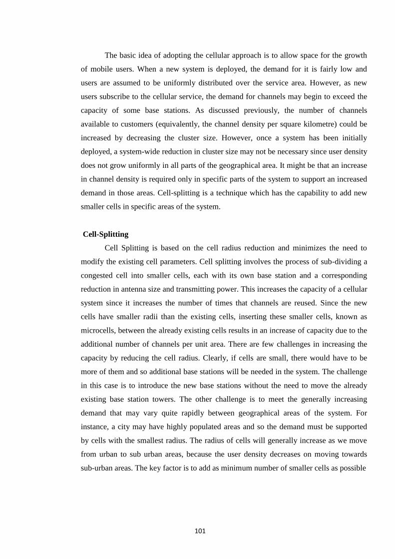
101
The basic idea of adopting the cellular approach is to allow space for the growth
of mobile users. When a new system is deployed, the demand for it is fairly low and
users are assumed to be uniformly distributed over the service area. However, as new
users subscribe to the cellular service, the demand for channels may begin to exceed the
capacity of some base stations. As discussed previously, the number of channels
available to customers (equivalently, the channel density per square kilometre) could be
increased by decreasing the cluster size. However, once a system has been initially
deployed, a system-wide reduction in cluster size may not be necessary since user density
does not grow uniformly in all parts of the geographical area. It might be that an increase
in channel density is required only in specific parts of the system to support an increased
demand in those areas. Cell-splitting is a technique which has the capability to add new
smaller cells in specific areas of the system.
Cell-Splitting
Cell Splitting is based on the cell radius reduction and minimizes the need to
modify the existing cell parameters. Cell splitting involves the process of sub-dividing a
congested cell into smaller cells, each with its own base station and a corresponding
reduction in antenna size and transmitting power. This increases the capacity of a cellular
system since it increases the number of times that channels are reused. Since the new
cells have smaller radii than the existing cells, inserting these smaller cells, known as
microcells, between the already existing cells results in an increase of capacity due to the
additional number of channels per unit area. There are few challenges in increasing the
capacity by reducing the cell radius. Clearly, if cells are small, there would have to be
more of them and so additional base stations will be needed in the system. The challenge
in this case is to introduce the new base stations without the need to move the already
existing base station towers. The other challenge is to meet the generally increasing
demand that may vary quite rapidly between geographical areas of the system. For
instance, a city may have highly populated areas and so the demand must be supported
by cells with the smallest radius. The radius of cells will generally increase as we move
from urban to sub urban areas, because the user density decreases on moving towards
sub-urban areas. The key factor is to add as minimum number of smaller cells as possible
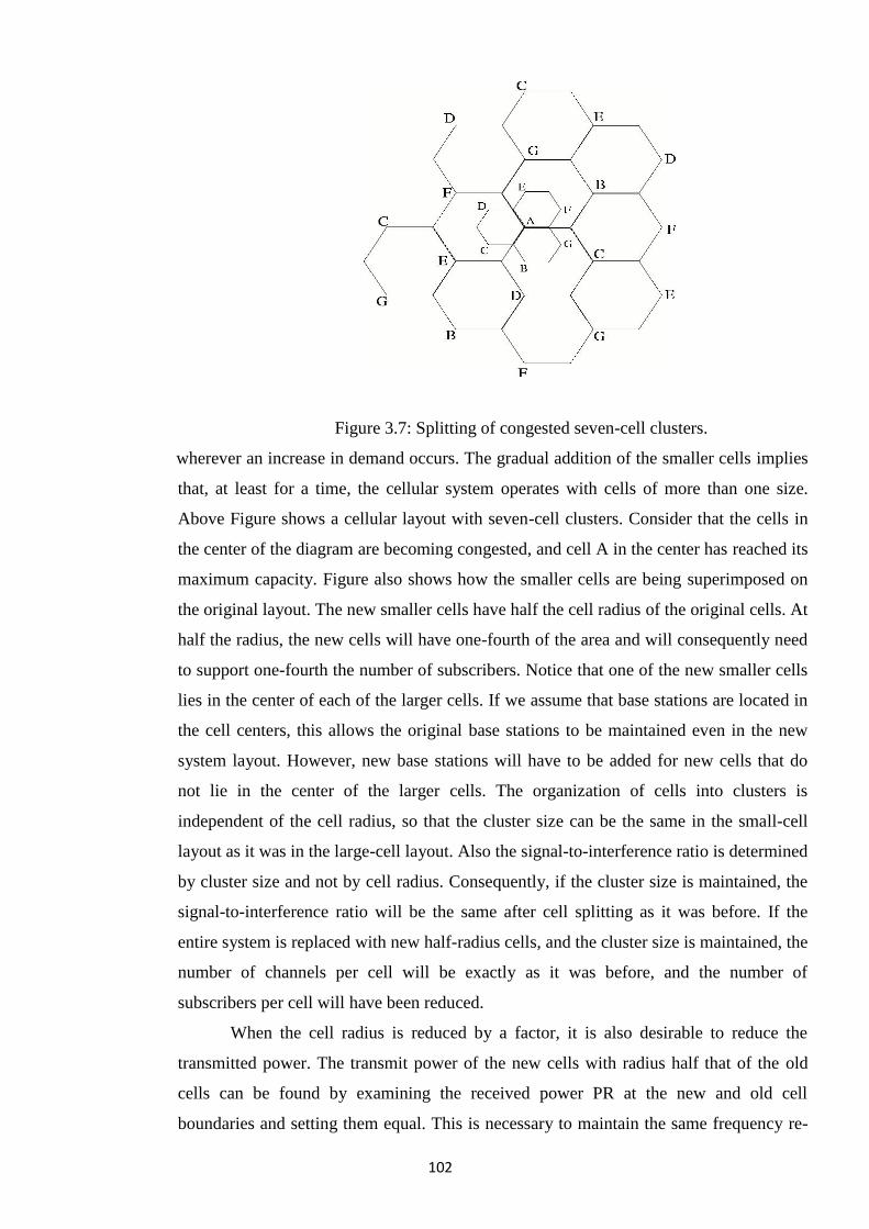
102
Figure 3.7: Splitting of congested seven-cell clusters.
wherever an increase in demand occurs. The gradual addition of the smaller cells implies
that, at least for a time, the cellular system operates with cells of more than one size.
Above Figure shows a cellular layout with seven-cell clusters. Consider that the cells in
the center of the diagram are becoming congested, and cell A in the center has reached its
maximum capacity. Figure also shows how the smaller cells are being superimposed on
the original layout. The new smaller cells have half the cell radius of the original cells. At
half the radius, the new cells will have one-fourth of the area and will consequently need
to support one-fourth the number of subscribers. Notice that one of the new smaller cells
lies in the center of each of the larger cells. If we assume that base stations are located in
the cell centers, this allows the original base stations to be maintained even in the new
system layout. However, new base stations will have to be added for new cells that do
not lie in the center of the larger cells. The organization of cells into clusters is
independent of the cell radius, so that the cluster size can be the same in the small-cell
layout as it was in the large-cell layout. Also the signal-to-interference ratio is determined
by cluster size and not by cell radius. Consequently, if the cluster size is maintained, the
signal-to-interference ratio will be the same after cell splitting as it was before. If the
entire system is replaced with new half-radius cells, and the cluster size is maintained, the
number of channels per cell will be exactly as it was before, and the number of
subscribers per cell will have been reduced.
When the cell radius is reduced by a factor, it is also desirable to reduce the
transmitted power. The transmit power of the new cells with radius half that of the old
cells can be found by examining the received power PR at the new and old cell
boundaries and setting them equal. This is necessary to maintain the same frequency re-
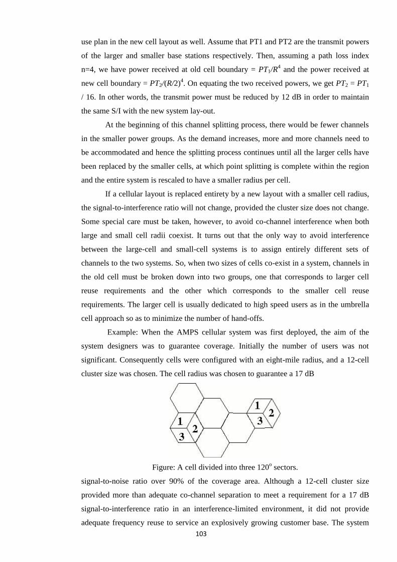
103
use plan in the new cell layout as well. Assume that PT1 and PT2 are the transmit powers
of the larger and smaller base stations respectively. Then, assuming a path loss index
n=4, we have power received at old cell boundary = PT1/R4 and the power received at
new cell boundary = PT2/(R/2)4. On equating the two received powers, we get PT2 = PT1
/ 16. In other words, the transmit power must be reduced by 12 dB in order to maintain
the same S/I with the new system lay-out.
At the beginning of this channel splitting process, there would be fewer channels
in the smaller power groups. As the demand increases, more and more channels need to
be accommodated and hence the splitting process continues until all the larger cells have
been replaced by the smaller cells, at which point splitting is complete within the region
and the entire system is rescaled to have a smaller radius per cell.
If a cellular layout is replaced entirety by a new layout with a smaller cell radius,
the signal-to-interference ratio will not change, provided the cluster size does not change.
Some special care must be taken, however, to avoid co-channel interference when both
large and small cell radii coexist. It turns out that the only way to avoid interference
between the large-cell and small-cell systems is to assign entirely different sets of
channels to the two systems. So, when two sizes of cells co-exist in a system, channels in
the old cell must be broken down into two groups, one that corresponds to larger cell
reuse requirements and the other which corresponds to the smaller cell reuse
requirements. The larger cell is usually dedicated to high speed users as in the umbrella
cell approach so as to minimize the number of hand-offs.
Example: When the AMPS cellular system was first deployed, the aim of the
system designers was to guarantee coverage. Initially the number of users was not
significant. Consequently cells were configured with an eight-mile radius, and a 12-cell
cluster size was chosen. The cell radius was chosen to guarantee a 17 dB
Figure: A cell divided into three 120o sectors.
signal-to-noise ratio over 90% of the coverage area. Although a 12-cell cluster size
provided more than adequate co-channel separation to meet a requirement for a 17 dB
signal-to-interference ratio in an interference-limited environment, it did not provide
adequate frequency reuse to service an explosively growing customer base. The system
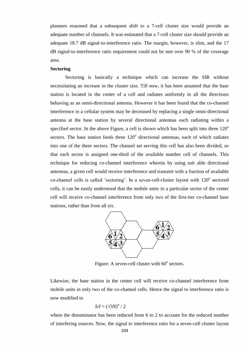
104
planners reasoned that a subsequent shift to a 7-cell cluster size would provide an
adequate number of channels. It was estimated that a 7-cell cluster size should provide an
adequate 18.7 dB signal-to-interference ratio. The margin, however, is slim, and the 17
dB signal-to-interference ratio requirement could not be met over 90 % of the coverage
area.
Sectoring
Sectoring is basically a technique which can increase the SIR without
necessitating an increase in the cluster size. Till now, it has been assumed that the base
station is located in the center of a cell and radiates uniformly in all the directions
behaving as an omni-directional antenna. However it has been found that the co-channel
interference in a cellular system may be decreased by replacing a single omni-directional
antenna at the base station by several directional antennas each radiating within a
specified sector. In the above Figure, a cell is shown which has been split into three 120o
sectors. The base station feeds three 120o directional antennas, each of which radiates
into one of the three sectors. The channel set serving this cell has also been divided, so
that each sector is assigned one-third of the available number cell of channels. This
technique for reducing co-channel interference wherein by using suit able directional
antennas, a given cell would receive interference and transmit with a fraction of available
co-channel cells is called ‘sectoring‘. In a seven-cell-cluster layout with 120o sectored
cells, it can be easily understood that the mobile units in a particular sector of the center
cell will receive co-channel interference from only two of the first-tier co-channel base
stations, rather than from all six.
Figure: A seven-cell cluster with 60o sectors.
Likewise, the base station in the center cell will receive co-channel interference from
mobile units in only two of the co-channel cells. Hence the signal to interference ratio is
now modified to
S/I = (√3N)n / 2
where the denominator has been reduced from 6 to 2 to account for the reduced number
of interfering sources. Now, the signal to interference ratio for a seven-cell cluster layout
105
using 120o sectored antennas can be found to be 23.4 dB which is a significant
improvement over the Omni-directional case where the worst-case S/I is found to be 17
dB (assuming a path-loss exponent, n=4). Some cellular systems divide the cells into 60o
sectors.
9.3 Wireless Systems and its Standards
Generations of Mobile Systems
1. 1st Generation (1G): Analog Transmission
AMPS (Advanced Mobile Phone System): North American cellular phone
standard operates in 800 MHz and 900 MHz bands. About 85% of AMPS
subscribers are in the U.S.
TACS (ETACS) (Total Access Communications System): derivative of AMPS
developed in U.K. 91% of TACS subscribers come from Europe.
NMT (Nordic Mobile Telephone): one of the first cellular systems, operates in
450 MHz and 900 MHz bands. Used in Scandinavian countries (Norway,
Sweden, Finland).
2. 2nd Generation (2G): Digital Transmission
GSM
CT2, CT3 (Cordless Telephone)
DECT (Digital European Cordless Telecommunications): a cordless system
supporting voice and data.
CDMA
3. 3rd Generation (3G): Unification of technologies
FPLMTS (Future Public Land Mobile Telecommunication Systems)
UMTS (Universal Mobile Telecom System)
CDMA2000, WCDMA (Wideband CDMA)
9.4 Global System for Mobile Communications (GSM)
What is GSM?
If you are in Europe, Asia or Japan and using a mobile phone, then most probably you
must be using GSM technology in your mobile phone.
GSM stands for Global System for Mobile Communication and is an open, digital
cellular technology used for transmitting mobile voice and data services.
The GSM emerged from the idea of cell-based mobile radio systems at Bell
Laboratories in the early 1970s.
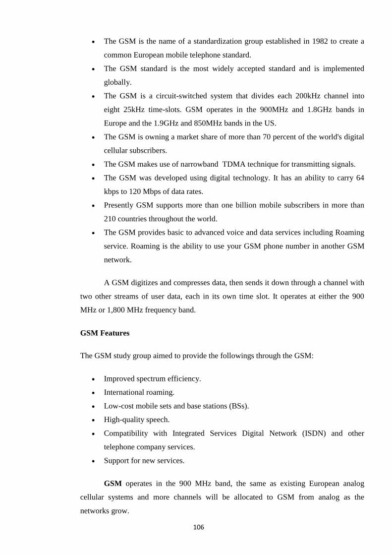
106
The GSM is the name of a standardization group established in 1982 to create a
common European mobile telephone standard.
The GSM standard is the most widely accepted standard and is implemented
globally.
The GSM is a circuit-switched system that divides each 200kHz channel into
eight 25kHz time-slots. GSM operates in the 900MHz and 1.8GHz bands in
Europe and the 1.9GHz and 850MHz bands in the US.
The GSM is owning a market share of more than 70 percent of the world's digital
cellular subscribers.
The GSM makes use of narrowband TDMA technique for transmitting signals.
The GSM was developed using digital technology. It has an ability to carry 64
kbps to 120 Mbps of data rates.
Presently GSM supports more than one billion mobile subscribers in more than
210 countries throughout the world.
The GSM provides basic to advanced voice and data services including Roaming
service. Roaming is the ability to use your GSM phone number in another GSM
network.
A GSM digitizes and compresses data, then sends it down through a channel with
two other streams of user data, each in its own time slot. It operates at either the 900
MHz or 1,800 MHz frequency band.
GSM Features
The GSM study group aimed to provide the followings through the GSM:
Improved spectrum efficiency.
International roaming.
Low-cost mobile sets and base stations (BSs).
High-quality speech.
Compatibility with Integrated Services Digital Network (ISDN) and other
telephone company services.
Support for new services.
GSM operates in the 900 MHz band, the same as existing European analog
cellular systems and more channels will be allocated to GSM from analog as the
networks grow.
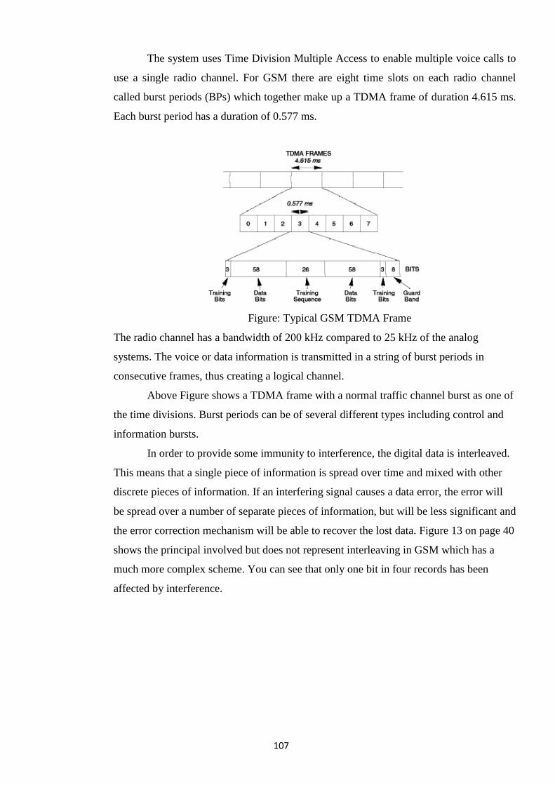
107
The system uses Time Division Multiple Access to enable multiple voice calls to
use a single radio channel. For GSM there are eight time slots on each radio channel
called burst periods (BPs) which together make up a TDMA frame of duration 4.615 ms.
Each burst period has a duration of 0.577 ms.
Figure: Typical GSM TDMA Frame
The radio channel has a bandwidth of 200 kHz compared to 25 kHz of the analog
systems. The voice or data information is transmitted in a string of burst periods in
consecutive frames, thus creating a logical channel.
Above Figure shows a TDMA frame with a normal traffic channel burst as one of
the time divisions. Burst periods can be of several different types including control and
information bursts.
In order to provide some immunity to interference, the digital data is interleaved.
This means that a single piece of information is spread over time and mixed with other
discrete pieces of information. If an interfering signal causes a data error, the error will
be spread over a number of separate pieces of information, but will be less significant and
the error correction mechanism will be able to recover the lost data. Figure 13 on page 40
shows the principal involved but does not represent interleaving in GSM which has a
much more complex scheme. You can see that only one bit in four records has been
affected by interference.
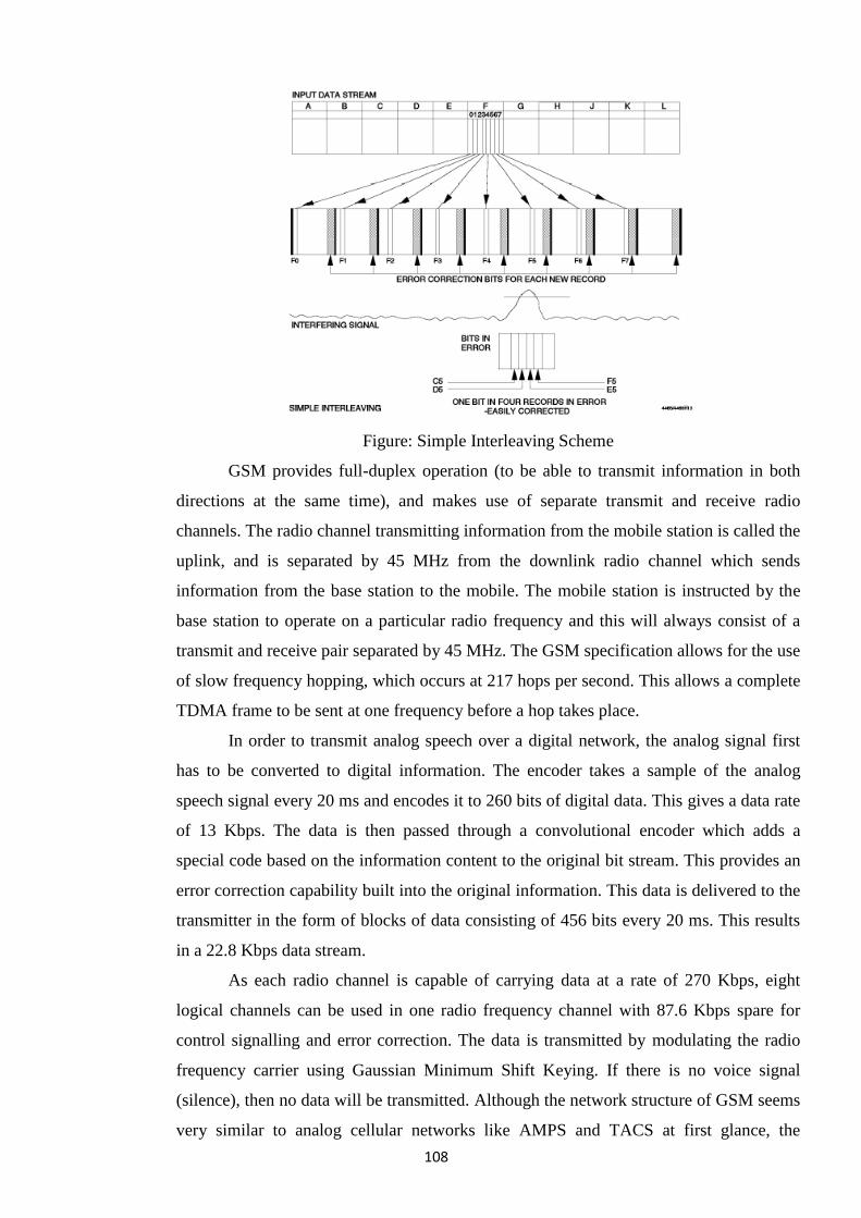
108
Figure: Simple Interleaving Scheme
GSM provides full-duplex operation (to be able to transmit information in both
directions at the same time), and makes use of separate transmit and receive radio
channels. The radio channel transmitting information from the mobile station is called the
uplink, and is separated by 45 MHz from the downlink radio channel which sends
information from the base station to the mobile. The mobile station is instructed by the
base station to operate on a particular radio frequency and this will always consist of a
transmit and receive pair separated by 45 MHz. The GSM specification allows for the use
of slow frequency hopping, which occurs at 217 hops per second. This allows a complete
TDMA frame to be sent at one frequency before a hop takes place.
In order to transmit analog speech over a digital network, the analog signal first
has to be converted to digital information. The encoder takes a sample of the analog
speech signal every 20 ms and encodes it to 260 bits of digital data. This gives a data rate
of 13 Kbps. The data is then passed through a convolutional encoder which adds a
special code based on the information content to the original bit stream. This provides an
error correction capability built into the original information. This data is delivered to the
transmitter in the form of blocks of data consisting of 456 bits every 20 ms. This results
in a 22.8 Kbps data stream.
As each radio channel is capable of carrying data at a rate of 270 Kbps, eight
logical channels can be used in one radio frequency channel with 87.6 Kbps spare for
control signalling and error correction. The data is transmitted by modulating the radio
frequency carrier using Gaussian Minimum Shift Keying. If there is no voice signal
(silence), then no data will be transmitted. Although the network structure of GSM seems
very similar to analog cellular networks like AMPS and TACS at first glance, the
109
underlying structure is much more complex. One of the main reasons for this is that the
architecture is structured to enable international roaming and the customer billing
processes that ensure a mobile phone can be used in different GSM networks.
The following is a list of the main GSM network components:
Base Transceiver Station (BTS)
The BTS transmits and receives to and from all GSM phones in its cell.
Base Station Controller (BSC)
The BSC controls several base stations and ensures that a mobile phone can move
from one cell to another and switch to the new radio channel without a break in
communication.
Mobile Switching Center (MSC)
The MSC is the way that the GSM network is connected to other networks such
as PSTN, ISDN or other mobile networks. It also controls call setup and
disconnect, call routing, and switching to other MSCs. It generates data for
customer billing systems.
Home Location Register (HLR)
The HLR contains information about the subscriber including level of service
allowed and location information.
Visitor Location Register (VLR)
The VLR obtains subscriber information from the subscriber‘s HLR when the
GSM phone is being used on a different network.
Equipment Identity Register (EIR)
The EIR is a database which contains information about the validity of
GSM telephones being used on the network. Each phone has an
International Mobile Equipment Identity number (IMEI) which is independent of
the subscriber number.
Authentication Center (AUC)
The AUC provides a security function to ensure that a call is being made by an
authorized phone.
Operations Management Center (OMC)
The OMC manages the network on a regional and day-to-day basis.
Network Management Centre (NMC)
The NMC manages the entire network on a global basis and is used for long-term
planning.
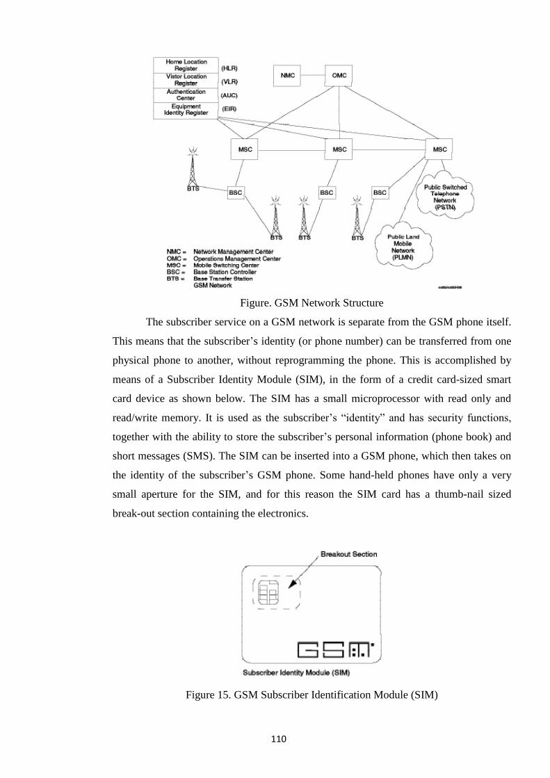
110
Figure. GSM Network Structure
The subscriber service on a GSM network is separate from the GSM phone itself.
This means that the subscriber‘s identity (or phone number) can be transferred from one
physical phone to another, without reprogramming the phone. This is accomplished by
means of a Subscriber Identity Module (SIM), in the form of a credit card-sized smart
card device as shown below. The SIM has a small microprocessor with read only and
read/write memory. It is used as the subscriber‘s ―identity‖ and has security functions,
together with the ability to store the subscriber‘s personal information (phone book) and
short messages (SMS). The SIM can be inserted into a GSM phone, which then takes on
the identity of the subscriber‘s GSM phone. Some hand-held phones have only a very
small aperture for the SIM, and for this reason the SIM card has a thumb-nail sized
break-out section containing the electronics.
Figure 15. GSM Subscriber Identification Module (SIM)
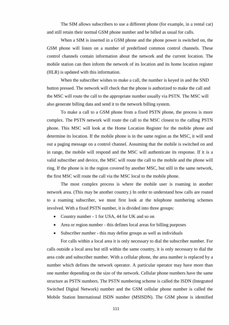
111
The SIM allows subscribers to use a different phone (for example, in a rental car)
and still retain their normal GSM phone number and be billed as usual for calls.
When a SIM is inserted in a GSM phone and the phone power is switched on, the
GSM phone will listen on a number of predefined common control channels. These
control channels contain information about the network and the current location. The
mobile station can then inform the network of its location and its home location register
(HLR) is updated with this information.
When the subscriber wishes to make a call, the number is keyed in and the SND
button pressed. The network will check that the phone is authorized to make the call and
the MSC will route the call to the appropriate number usually via PSTN. The MSC will
also generate billing data and send it to the network billing system.
To make a call to a GSM phone from a fixed PSTN phone, the process is more
complex. The PSTN network will route the call to the MSC closest to the calling PSTN
phone. This MSC will look at the Home Location Register for the mobile phone and
determine its location. If the mobile phone is in the same region as the MSC, it will send
out a paging message on a control channel. Assuming that the mobile is switched on and
in range, the mobile will respond and the MSC will authenticate its response. If it is a
valid subscriber and device, the MSC will route the call to the mobile and the phone will
ring. If the phone is in the region covered by another MSC, but still in the same network,
the first MSC will route the call via the MSC local to the mobile phone.
The most complex process is where the mobile user is roaming in another
network area. (This may be another country.) In order to understand how calls are routed
to a roaming subscriber, we must first look at the telephone numbering schemes
involved. With a fixed PSTN number, it is divided into three groups:
Country number - 1 for USA, 44 for UK and so on
Area or region number - this defines local areas for billing purposes
Subscriber number - this may define groups as well as individuals
For calls within a local area it is only necessary to dial the subscriber number. For
calls outside a local area but still within the same country, it is only necessary to dial the
area code and subscriber number. With a cellular phone, the area number is replaced by a
number which defines the network operator. A particular operator may have more than
one number depending on the size of the network. Cellular phone numbers have the same
structure as PSTN numbers. The PSTN numbering scheme is called the ISDN (Integrated
Switched Digital Network) number and the GSM cellular phone number is called the
Mobile Station International ISDN number (MSISDN). The GSM phone is identified
112
over the air interface by a different numbering scheme. This is the International Mobile
Subscriber Identity (IMSI) or Temporary IMSI (TIMSI). This allows the phone to be
identified regardless of its home.
When a call is made to a phone roaming outside its home location, the call is
routed to a gateway MSC (GMSC) in its home network. The GMSC interrogates the
Home Location Register (HLR), which contains information about where the mobile
phone is currently located. This information is obtained from the Visitor Location
Register (VLR) of the network where the phone is located and includes a Mobile Station
Roaming Number (MSRN) that is assigned to the mobile phone. Using this information,
the GMSC routes the call to the new network MSC (which may be via an international
link). The host MSC pages the mobile phone and the call is connected after validation.
A call directed to a phone roaming outside its home network will always be
routed via a gateway MSC in its home network. One problem that arises from this is that
if a call is made from one GSM phone to another, both roaming out of their home
networks, then it is possible that they will be charged for a double international call even
if they are next to each other in the same room. This is because the phone making the call
will be charged for a call back to its home network GMSC and the phone receiving the
call will be charged for a call from its home GMSC to its current location. There is no
way of avoiding this situation without causing an unacceptable increase in billing
complexity for average calls.
One of the main reasons for implementing GSM is the new services that can be
offered. One of the first of these is the Short Message Service (SMS). This allows the
GSM phone to send and receive short messages, using the network‘s control channel to
transfer the information. This means that no circuit-switched connection is established
and the message can be stored and forwarded when the phone is able to accept the
message. The GSM Short Message Service allows the phone to act like a two-way
alphanumeric pager. Up to 160 characters can be transmitted in one message. One
implementation of the service provides access via a normal paging bureau, or direct from
a customer‘s host system. The mobile phone subscriber can respond by entering a
message using the phone‘s keypad to emulate an alphanumeric keyboard. This can be
quite laborious for longer messages, but useful for short acknowledgements.
One way to simplify this operation is to store a number of predefined messages in
the phone‘s memory and modify them as necessary before sending them. An alternative
method is to connect the phone to a notebook computer or PDA and use that device‘s
keyboard. SMS messages can be sent from host to mobile, mobile to mobile, or mobile to
113
host. In the latter case it will depend on the network operator‘s implementation of the
service. If a standard one-way paging bureau service is used for SMS access, then a
direct connection back to a customer‘s host system may not be possible. SMS messages
can be stored in the phone‘s own memory or in the subscriber‘s SIM memory. This is
especially useful if the subscriber is using a different phone from his own, but with his
SIM inserted. SMS messages can also be broadcast to a number of subscribers at the
same time. This is known as ―cell broadcast‖. All mobiles within a defined area that are
equipped with this feature will receive the broadcast, and no special subscription is
needed. This can be used for things such as traffic information, weather warnings and the
like. The cell broadcast is limited to 93 characters. Apart from private messaging
services, SMS can be used by network operators to communicate with subscribers and
even download new phone configurations to enable other services. Other applications
will be developed as networks grow.
In order to send circuit-switched data over a GSM network, it is important to
understand that the air link is digital and that the encoding and compression algorithms
are designed to expect speech information. It is therefore impossible to use ordinary
PSTN compatible modems to send data over a GSM network. The GSM specification
includes data services for fax, circuit-switched, and packet-switched data. The first
implementation of GSM does not include packet-switched data. In order to send circuit-
switched data, the network operator must provide a mechanism that allows digital
information sent from a host computer to be encoded directly in the GSM air protocol. In
addition, if the data is to be transmitted over the PSTN, the network operator must
provide modems to match the end-user requirements. In the mobile phone itself, the data
connection bypasses the analog /digital conversion and also bypasses the voice
compression circuits. There is no need for a modem at the mobile end; the connections
are all digital. At the fixed station (MSC), voice and data calls are separated.
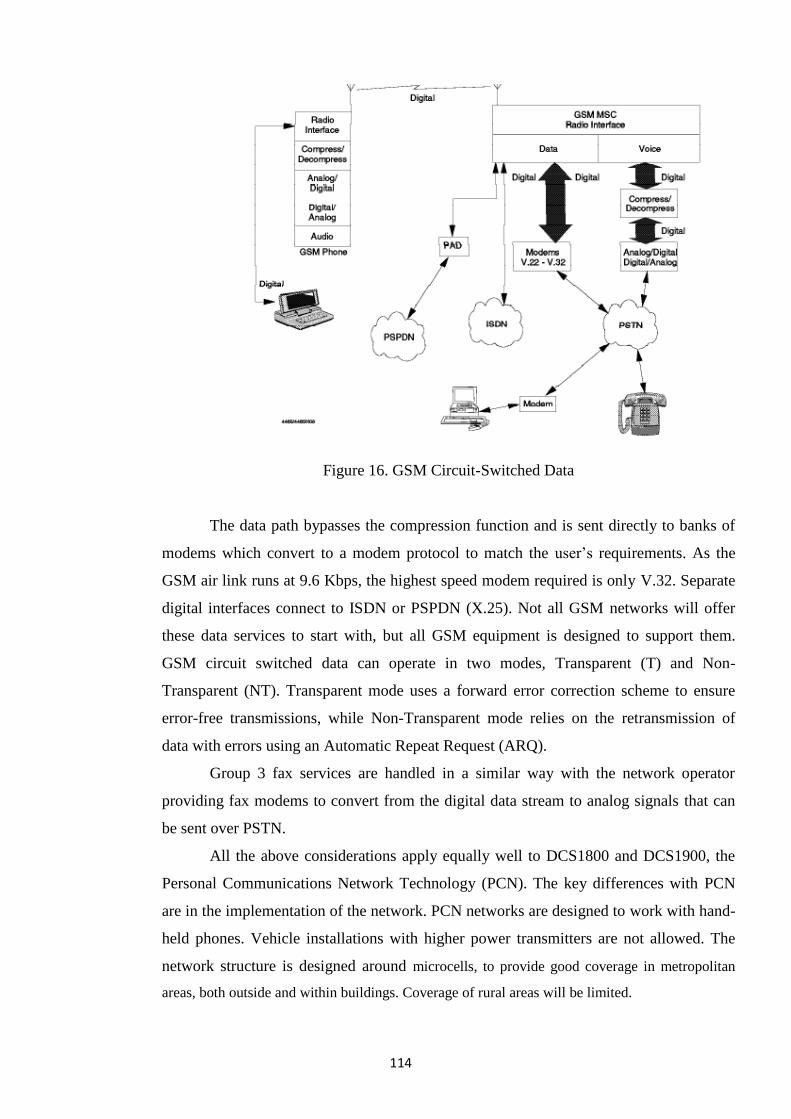
114
Figure 16. GSM Circuit-Switched Data
The data path bypasses the compression function and is sent directly to banks of
modems which convert to a modem protocol to match the user‘s requirements. As the
GSM air link runs at 9.6 Kbps, the highest speed modem required is only V.32. Separate
digital interfaces connect to ISDN or PSPDN (X.25). Not all GSM networks will offer
these data services to start with, but all GSM equipment is designed to support them.
GSM circuit switched data can operate in two modes, Transparent (T) and Non-
Transparent (NT). Transparent mode uses a forward error correction scheme to ensure
error-free transmissions, while Non-Transparent mode relies on the retransmission of
data with errors using an Automatic Repeat Request (ARQ).
Group 3 fax services are handled in a similar way with the network operator
providing fax modems to convert from the digital data stream to analog signals that can
be sent over PSTN.
All the above considerations apply equally well to DCS1800 and DCS1900, the
Personal Communications Network Technology (PCN). The key differences with PCN
are in the implementation of the network. PCN networks are designed to work with hand-
held phones. Vehicle installations with higher power transmitters are not allowed. The
network structure is designed around microcells, to provide good coverage in metropolitan
areas, both outside and within buildings. Coverage of rural areas will be limited.
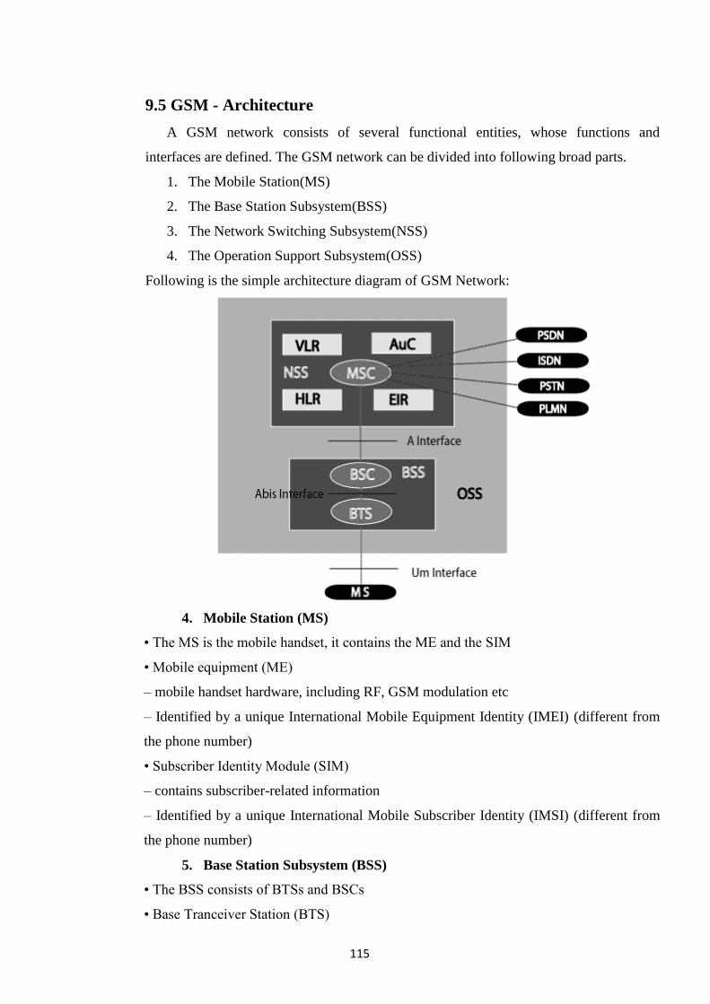
115
9.5 GSM - Architecture
A GSM network consists of several functional entities, whose functions and
interfaces are defined. The GSM network can be divided into following broad parts.
1. The Mobile Station(MS)
2. The Base Station Subsystem(BSS)
3. The Network Switching Subsystem(NSS)
4. The Operation Support Subsystem(OSS)
Following is the simple architecture diagram of GSM Network:
4. Mobile Station (MS)
• The MS is the mobile handset, it contains the ME and the SIM
• Mobile equipment (ME)
– mobile handset hardware, including RF, GSM modulation etc
– Identified by a unique International Mobile Equipment Identity (IMEI) (different from
the phone number)
• Subscriber Identity Module (SIM)
– contains subscriber-related information
– Identified by a unique International Mobile Subscriber Identity (IMSI) (different from
the phone number)
5. Base Station Subsystem (BSS)
• The BSS consists of BTSs and BSCs
• Base Tranceiver Station (BTS)
116
– responsible for communication with the MS
– responsible for radio transmission and reception
– includes antennas, modems, signal processing
• Base Station Controller (BSC)
– responsible for radio interface management of BTS and MS, i.e. channel management
and handovers
– responsible for communication with the NSS
– a single BSC typically manages 10-20 BTSs
6. Network and Switching Subsystem (NSS)
• NSS contains the switching functions of GSM, as well as databases for mobility
management
• NSS contains
– Mobile Switching Centre (MSC)
– Gateway MSC (GMSC)
– Home Location Register (HLR) - co-located with GMSC
– Visitor Location Register (VLR) - co-located with MSC/GMSC
• Signalling between MSC, GMSC, HLR, VLR via SS7 signalling network, using
specifically the mobile application part (MAP) of Signalling System No 7 (SS7)
• Mobile Switching Centre (MSC)
– coordinates setup of calls to and from GSM users
– controls several BSCs
• Gateway MSC (GMSC)
– gateway to external network
– incoming call is routed to GMSC, which then determines
MS location
– GMSC function is often in the same machine as the MSC
Home Location Register (HLR)
– contains information about subscribers, e.g. subscriber profiles, also information on
their current location
– IMSI, user phone number, address of current VLR etc
• Visitor Location Register (VLR)
– temporarily stores subscription data for subscribers currently in the (G)MSC area
– contains more precise location data than does the HLR
– linked to one or more MSCs
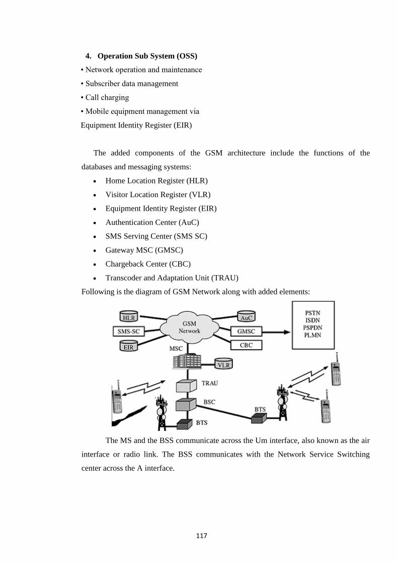
117
4. Operation Sub System (OSS)
• Network operation and maintenance
• Subscriber data management
• Call charging
• Mobile equipment management via
Equipment Identity Register (EIR)
The added components of the GSM architecture include the functions of the
databases and messaging systems:
Home Location Register (HLR)
Visitor Location Register (VLR)
Equipment Identity Register (EIR)
Authentication Center (AuC)
SMS Serving Center (SMS SC)
Gateway MSC (GMSC)
Chargeback Center (CBC)
Transcoder and Adaptation Unit (TRAU)
Following is the diagram of GSM Network along with added elements:
The MS and the BSS communicate across the Um interface, also known as the air
interface or radio link. The BSS communicates with the Network Service Switching
center across the A interface.
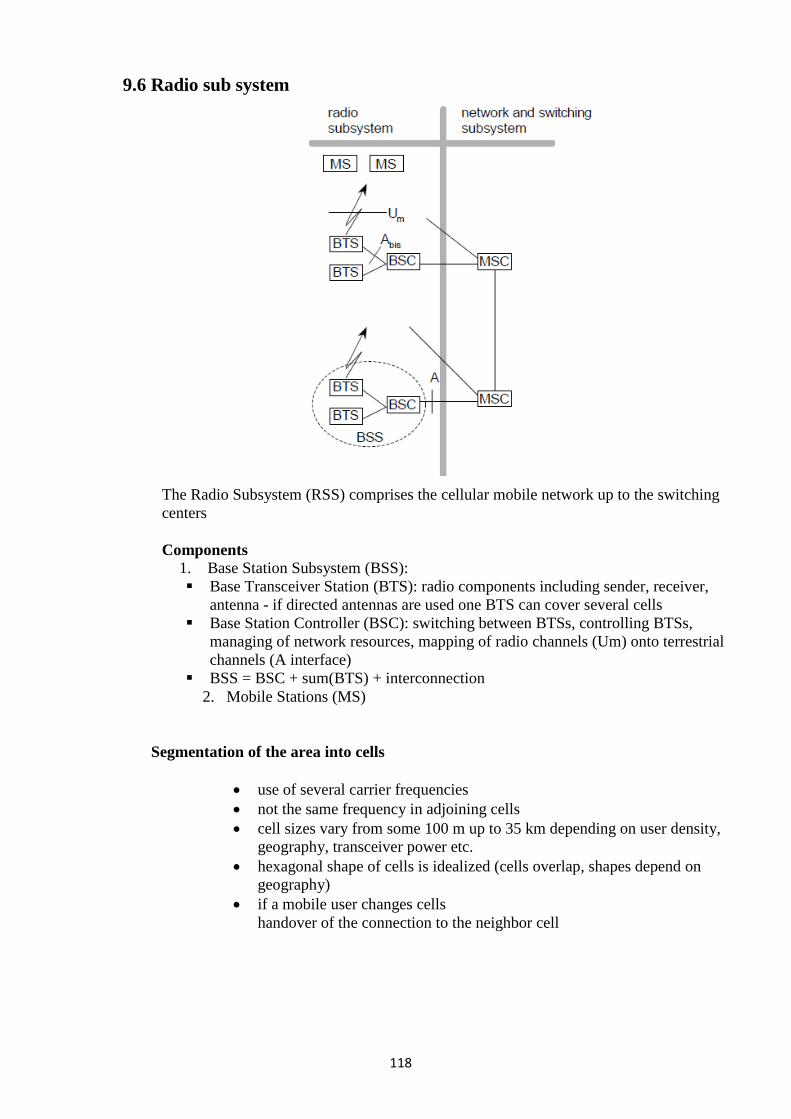
118
9.6 Radio sub system
The Radio Subsystem (RSS) comprises the cellular mobile network up to the switching
centers
Components
1. Base Station Subsystem (BSS):
Base Transceiver Station (BTS): radio components including sender, receiver,
antenna - if directed antennas are used one BTS can cover several cells
Base Station Controller (BSC): switching between BTSs, controlling BTSs,
managing of network resources, mapping of radio channels (Um) onto terrestrial
channels (A interface)
BSS = BSC + sum(BTS) + interconnection
2. Mobile Stations (MS)
Segmentation of the area into cells
use of several carrier frequencies
not the same frequency in adjoining cells
cell sizes vary from some 100 m up to 35 km depending on user density,
geography, transceiver power etc.
hexagonal shape of cells is idealized (cells overlap, shapes depend on
geography)
if a mobile user changes cells
handover of the connection to the neighbor cell
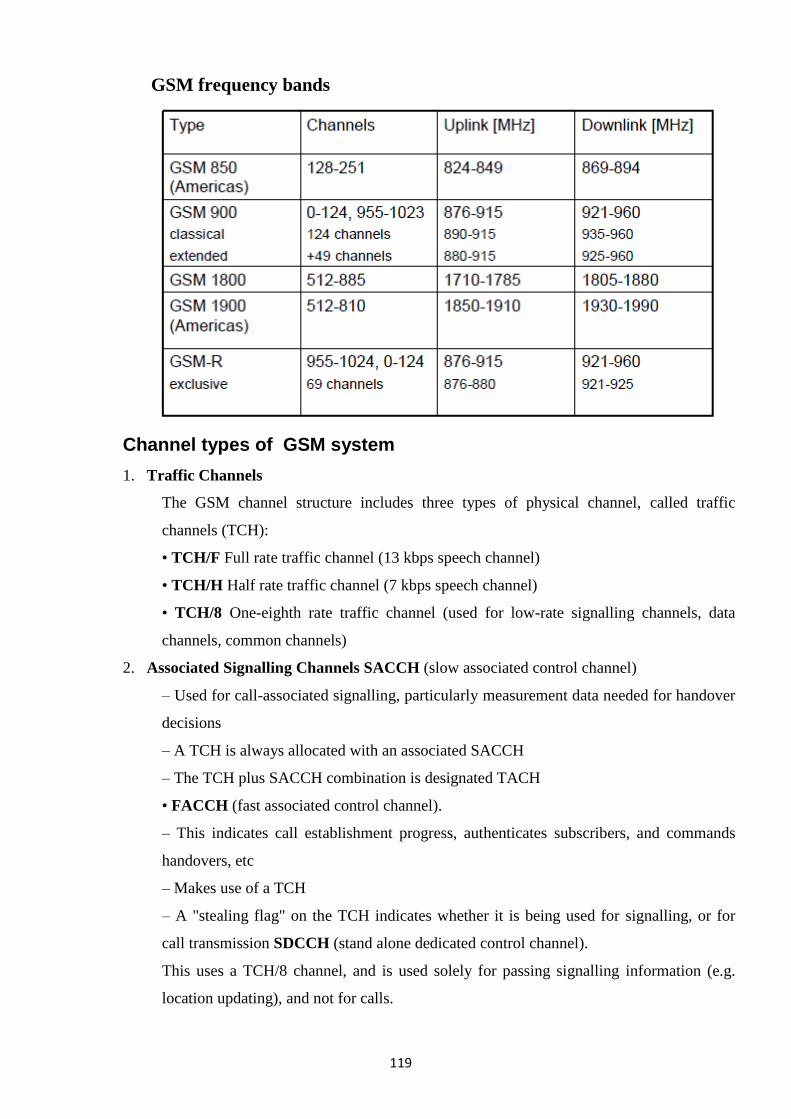
119
GSM frequency bands
Channel types of GSM system
1. Traffic Channels
The GSM channel structure includes three types of physical channel, called traffic
channels (TCH):
• TCH/F Full rate traffic channel (13 kbps speech channel)
• TCH/H Half rate traffic channel (7 kbps speech channel)
• TCH/8 One-eighth rate traffic channel (used for low-rate signalling channels, data
channels, common channels)
2. Associated Signalling Channels SACCH (slow associated control channel)
– Used for call-associated signalling, particularly measurement data needed for handover
decisions
– A TCH is always allocated with an associated SACCH
– The TCH plus SACCH combination is designated TACH
• FACCH (fast associated control channel).
– This indicates call establishment progress, authenticates subscribers, and commands
handovers, etc
– Makes use of a TCH
– A "stealing flag" on the TCH indicates whether it is being used for signalling, or for
call transmission SDCCH (stand alone dedicated control channel).
This uses a TCH/8 channel, and is used solely for passing signalling information (e.g.
location updating), and not for calls.
120
3. Common Signalling Channels Downlink channels (base station to mobile):
• FCCH (frequency correction channel) is used to identify a beacon frequency
• SCH (synchronisation channel) follows each FCCH to obtain synchronisation
• BCCH (broadcast control channel) is broadcast regularly and received by each mobile
station while it is in the idle mode. It gives information about the cell, such as which
network the cell belongs to.
• PAGCH (paging and access grant channel) is used to page a called mobile, and to
allocate a channel during call set-up. There may be a full rate PAGCH/F or a one-third
rate PAGCH/T.
• CBCH (cell broadcast channel) can be used to transmit one 80 octet message every 2
seconds. It uses half a TCH/8 channel.
How cell selection works:
The MS finds the FCCH burst, then looks for an SCH burst on the same frequency to
obtain frame synchronisation. The MS then receives BCCH on several time slots and
selects a proper cell.
4. Uplink channels (mobile station to base station):
There is only one common access channel on the uplink
• RACH (random-access channel).
The MS uses this channel to access the network. These may be provided as a full rate
RACH/F or a half rate RACH/H.
9.8 CDMA FORWARD AND REVERSE CHANNELS
Forward Channels
The Forward CDMA channel is the cell-to-mobile direction of communication or
the downlink path. It consists of:
Pilot Channel is a reference channel which the mobile station uses for acquisition,
timing and as a phase reference for coherent demodulation. It is transmitted at all times
by each base station on each active CDMA frequency. Each mobile station tracks this
signal continuously.
Sync Channel carries a single, repeating message that conveys the timing and system
configuration information to the mobile station in the CDMA system.
Paging Channels’ primary purpose is to send out pages, that is, notifications of
incoming calls, to the mobile stations. The base station uses them to transmit system
overhead information and mobile station- specific messages.
Forward Traffic Channels are code channels used to assign call (usually voice) and
signaling traffic to individual users.
121
Reverse Channels
The Reverse CDMA channel is the mobile-to-cell direction of communication or the
uplink path.
Access Channels are used by mobile stations to initiate communication with the base
station or to respond to Paging Channel messages. The Access Channel is used for short
signaling message exchanges such as call origination's, responses to pages, and
registrations.
Reverse Traffic Channels are used by individual users during their actual calls to
transmit traffic from a single mobile station to one or more base stations.
9.9 GPRS
GPRS (General Packet Radio Service) is a packet based communication service
for mobile devices that allows data to be sent and received across a mobile telephone
network. GPRS is a step towards 3G and is often referred to as 2.5G. Here are some key
benefits of GPRS:
Speed
GPRS is packet switched. Higher connection speeds are attainable at around 56–
118 kbps, a vast improvement on circuit switched networks of 9.6 kbps. By combining
standard GSM time slots theoretical speeds of 171.2 kbps are attainable. However in the
very short term, speeds of 20-50 kbps are more realistic.
Always on connectivity
GPRS is an always-on service. There is no need to dial up like you have to on a
home PC for instance. This feature is not unique to GPRS but is an important standard
that will no doubt be a key feature for migration to 3G. It makes services instantaneously
available to a device.
New and Better applications
Due to its high-speed connection and always-on connectivity GPRS enables full
Internet applications and services such as video conferencing straight to your desktop or
mobile device. Users are able to explore the Internet or their own corporate networks
more efficiently than they could when using GSM. There is often no need to redevelop
existing applications.
GSM operator Costs
GSM network providers do not have to start from scratch to deploy GPRS. GPRS
is an upgrade to the existing network that sits alongside the GSM network. This makes it
easier to deploy, there is little or no downtime of the existing GSM network whilst
implementation takes place, most updates are software so they can be administered
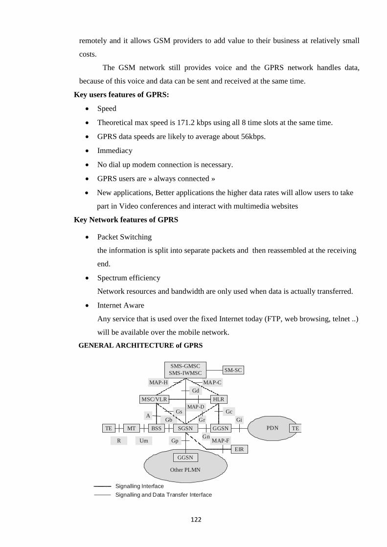
122
remotely and it allows GSM providers to add value to their business at relatively small
costs.
The GSM network still provides voice and the GPRS network handles data,
because of this voice and data can be sent and received at the same time.
Key users features of GPRS:
Speed
Theoretical max speed is 171.2 kbps using all 8 time slots at the same time.
GPRS data speeds are likely to average about 56kbps.
Immediacy
No dial up modem connection is necessary.
GPRS users are » always connected »
New applications, Better applications the higher data rates will allow users to take
part in Video conferences and interact with multimedia websites
Key Network features of GPRS
Packet Switching
the information is split into separate packets and then reassembled at the receiving
end.
Spectrum efficiency
Network resources and bandwidth are only used when data is actually transferred.
Internet Aware
Any service that is used over the fixed Internet today (FTP, web browsing, telnet ..)
will be available over the mobile network.
GENERAL ARCHITECTURE of GPRS
MAP-F
Gi
Gn
Gb
Gc MAP-D
MAP-C MAP-H
Gp
Gs
Signalling and Data Transfer Interface
Signalling Interface
MSC/VLR
TE MT BSS TE PDN
R Um
Gr A
HLR
Other PLMN
SGSN
GGSN
Gd
SM-SC SMS-GMSC
SMS-IWMSC
GGSN
EIR
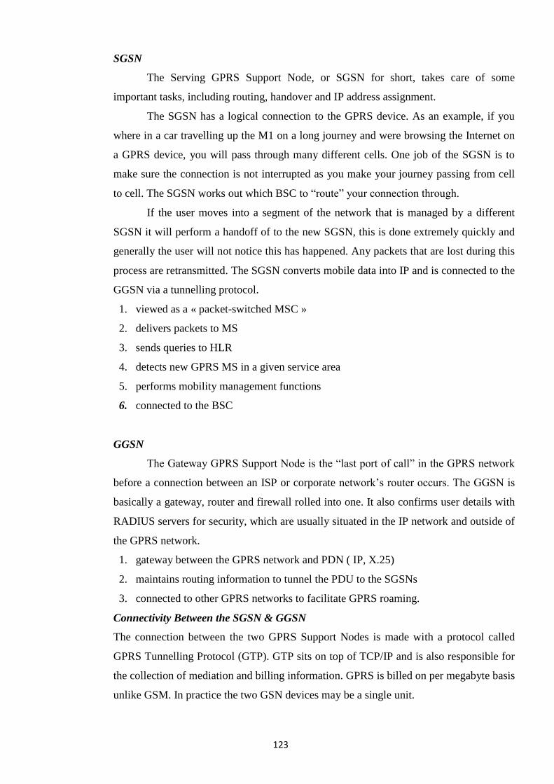
123
SGSN
The Serving GPRS Support Node, or SGSN for short, takes care of some
important tasks, including routing, handover and IP address assignment.
The SGSN has a logical connection to the GPRS device. As an example, if you
where in a car travelling up the M1 on a long journey and were browsing the Internet on
a GPRS device, you will pass through many different cells. One job of the SGSN is to
make sure the connection is not interrupted as you make your journey passing from cell
to cell. The SGSN works out which BSC to ―route‖ your connection through.
If the user moves into a segment of the network that is managed by a different
SGSN it will perform a handoff of to the new SGSN, this is done extremely quickly and
generally the user will not notice this has happened. Any packets that are lost during this
process are retransmitted. The SGSN converts mobile data into IP and is connected to the
GGSN via a tunnelling protocol.
1. viewed as a « packet-switched MSC »
2. delivers packets to MS
3. sends queries to HLR
4. detects new GPRS MS in a given service area
5. performs mobility management functions
6. connected to the BSC
GGSN
The Gateway GPRS Support Node is the ―last port of call‖ in the GPRS network
before a connection between an ISP or corporate network‘s router occurs. The GGSN is
basically a gateway, router and firewall rolled into one. It also confirms user details with
RADIUS servers for security, which are usually situated in the IP network and outside of
the GPRS network.
1. gateway between the GPRS network and PDN ( IP, X.25)
2. maintains routing information to tunnel the PDU to the SGSNs
3. connected to other GPRS networks to facilitate GPRS roaming.
Connectivity Between the SGSN & GGSN
The connection between the two GPRS Support Nodes is made with a protocol called
GPRS Tunnelling Protocol (GTP). GTP sits on top of TCP/IP and is also responsible for
the collection of mediation and billing information. GPRS is billed on per megabyte basis
unlike GSM. In practice the two GSN devices may be a single unit.
124
HLR
The HLR or Home Location Register is a database that contains subscriber information,
when a device connects to the network their MSISDN number is associated with
services, account status information, preferences and sometimes IP addresses.
9.10 Mobile TCP, IP protocol
What for Mobile IP?
• Routing
– based on IP destination address, network prefix (e.g. 129.132.13) determines physical
subnet
– change of physical subnet implies change of IP address to have a topological correct
address (standard IP) or needs special entries in the routing tables
• Changing the IP-address?
– adjust the host IP address depending on the current location
– almost impossible to find a mobile system, DNS updates are too slow
– TCP connections break
– security problems
• Change/Add routing table entries for mobile hosts?
– worldwide!
– does not scale with the number of mobile hosts and frequent changes in their location
Mobile IP
• Mobile IP was developed for IPv4, but IPv6 simplifies the protocols
– security is integrated and not an add-on, authentication of registration is included
– COA can be assigned via auto-configuration (DHCPv6 is one candidate), every node
has address auto-configuration
– no need for a separate FA, all routers perform router advertisement which can be used
instead of the special agent advertisement
– MN can signal a sender directly the COA, sending via HA not needed in this case
(automatic path optimization)
– ―soft‖ hand-over, i.e. without packet loss, between two subnets is supported
• MN sends the new COA to its old router
• the old router encapsulates all incoming packets for the MN and forwards them to the
new COA
• authentication is always granted
125
TCP Overview
• Transport control protocols typically designed for
– Fixed end-systems in wired networks
• Research activities
– Performance
– Congestion control
– Efficient retransmissions
• TCP congestion control
– packet loss in fixed networks typically due to
(temporary) overload situations
– router have to discard packets as soon as the buffers are full
– TCP recognizes congestion only indirectly via missing acknowledgements,
retransmissions unwise, they would only contribute to the congestion and make it even
worse
TCP fast retransmit/fast recovery
• TCP sends an acknowledgement only after receiving a packet
• If a sender receives several acknowledgements for the same packet, this is due to a gap
in received packets at the receiver
• Sender can retransmit missing packets (fast retransmit)
• Also, the receiver got all packets up to the gap and is actually receiving packets
• Therefore, packet loss is not due to congestion, continue with current congestion
window (fast recovery)
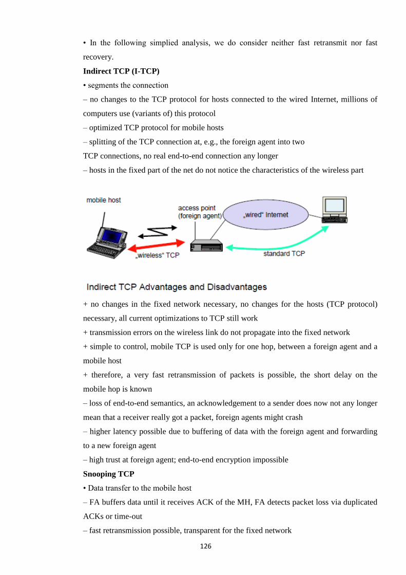
126
• In the following simplied analysis, we do consider neither fast retransmit nor fast
recovery.
Indirect TCP (I-TCP)
• segments the connection
– no changes to the TCP protocol for hosts connected to the wired Internet, millions of
computers use (variants of) this protocol
– optimized TCP protocol for mobile hosts
– splitting of the TCP connection at, e.g., the foreign agent into two
TCP connections, no real end-to-end connection any longer
– hosts in the fixed part of the net do not notice the characteristics of the wireless part
+ no changes in the fixed network necessary, no changes for the hosts (TCP protocol)
necessary, all current optimizations to TCP still work
+ transmission errors on the wireless link do not propagate into the fixed network
+ simple to control, mobile TCP is used only for one hop, between a foreign agent and a
mobile host
+ therefore, a very fast retransmission of packets is possible, the short delay on the
mobile hop is known
– loss of end-to-end semantics, an acknowledgement to a sender does now not any longer
mean that a receiver really got a packet, foreign agents might crash
– higher latency possible due to buffering of data with the foreign agent and forwarding
to a new foreign agent
– high trust at foreign agent; end-to-end encryption impossible
Snooping TCP
• Data transfer to the mobile host
– FA buffers data until it receives ACK of the MH, FA detects packet loss via duplicated
ACKs or time-out
– fast retransmission possible, transparent for the fixed network
127
• Data transfer from the mobile host
– FA detects packet loss on the wireless link via sequence numbers, FA answers directly
with a NACK to the MH
– MH can now retransmit data with only a very short delay
• Integration of the MAC layer
– MAC layer often has similar mechanisms to those of TCP
– thus, the MAC layer can already detect duplicated packets due to retransmissions and
discard them
• Problems
– snooping TCP does not isolate the wireless link as good as I-TCP
– snooping might be useless depending on encryption schemes
9.11 Wireless Application Protocol (WAP)?
The WAP standard specifies a set of protocols and an application environment for
The delivery of interactive and real-time information services over a mobile network to
conforming hand-held digital devices. Examples of such devices are PDAs and mobile
Telephones with displays. WAP aims to integrate Internet, wireless data, and telephony.
WAP works with all types of wireless networks including GSM, TDMA, CDMA,
and the upcoming 3G networks.
WAP is the wireless counterpart of the Internet protocol HTTP and the Web mark up
Language HTML. WAP addresses issues relating to wireless interaction, which is
characterized by low bandwidth and devices with small displays, limited processing
power and memory, and batteries that can operate only for limited periods without being
recharged.
Although WAP follows the client-server Web model of interaction, WAP is
Incompatible with HTTP and HTML. Consequently, WAP gateways (proxies) are
needed to sit between the client (WAP device) and the Web servers. Incidentally, the
newer version of WAP, WAP 2.0, supports HTTP, but a gateway is still required for
reasons such as WML compression, dynamic conversion of HTML to WML, etc.
WAP gateways intercept and hand lea user requests to Web servers and process
the responses. A Web server may generate WML content for WAP devices or it may
simply dish out HTML (or XML). In case the Web server generates HTML (XML), the
WAP gateways must convert the HTML (XML) to WML. Before sending the WML to
the WAP device, the gateway compresses it to WMLC (the Cin WMLC is for
128
compressed). If the WML generated by the Web server is already WMLC, then the
compression step is skipped and the server response passed on to the WAP device.
What are the Components of WAP?
The major component so for the WAP (actually WAP 2.0) specification is:
- Protocol Support
− IP networks: Protocols supported include the wireless ―profiled‖ versions of TCP
(called WP-TCP), TLS, and HTTP(called WP-HTTP).
− Non-IP networks: Wireless Session Protocol (WSP), Wireless Transaction Protocol
(WTP), Wireless Transport Layer Security (WTLS), and Wireless
Datagram Protocol (WDP).
- Application Environment
− WML Specification: WML is a mark up language like HTML based on XML and
XHTML (the XML version of HTML). WML is designed for devices with small screens,
limited processing power, and low bandwidth connection to the servers.
− WML Script Specification: WML Script is a scripting language, similar to JavaScript,
for running code on clients.
− WAP Micro Browser. The WAP micro browser is designed especially for operating in
the limited resource environment of WAP devices.
Service sand Capabilities
− Real-time Content Delivery: WAP provides facilities for asynchronously ―pushing‖
content to WAP devices allowing the immediate delivery of real time messages, alerts,
and other content that needs to be delivered immediately.
− Customization of User Profile: WAP allows servers to customize content delivered to
users based on user preferences and client device capabilities.
− Telephony Support: WAP enables telephone services to be operated from
With in a data environment. Consequently, WAP phone scan operate as integrated voice
and web devices.
What are the Advantages of WAP?
Using WAP, which is a global and open standard, has the following advantages:
Portability: A WAP application on one network should be easily portable to a
different environment with little or no change. The alternative to using WAP is to
write applications using proprietary protocols. Such applications will require
substantial code rewriting when porting to a
− different type of network(examples of network types are GSM and CDMA),
129
− different bearer protocol (examples of be are r protocols are SMS, short
Message service or CSD, circuit switched data), or
− a new device type.
User Experience: WAP aims to enhance the user experience by addressing
characteristics of wireless environment:
− Narrow bandwidth connection.
− Devices with small screens, limited battery use without recharging, Limited memory,
and limited processing power.
Cost and Application Development Time Reduction: New services can be added
quickly and at a lower cost using WAP. This is made possible by the easy
availability of standardized WAP tools and platforms such as WAP software
development tool kits, WAP gateways, and WAP devices.
9.12 Architecture and Features of SMS (Short Message Service)
What is SMS? : Short Message Service (SMS) is the transmission of short text
messages to and from a mobile phone, fax machine, and/or IP address. Messages must be
no longer than 160 alphanumeric characters and contain no images or graphics. SMS is a
relatively simple messaging system provided by the mobile phone networks. SMS
messages are supported by GSM, TDMA and CDMA based mobile phone networks
currently in use. Although services based on SMS have been feasible for many years, the
recent mobile phone penetration and large scale adoption of the existing services by users
have made the SMS based services even more attractive to service providers.
Once a message is sent, it is received by a Short Message Service Center
(SMSC), which must then direct it to the appropriate mobile device. To do this, the
SMSC sends a SMS Request to the home location register (HLR) to find the roaming
customer. Once the HLR receives the request, it will respond to the SMSC with the
subscriber's status: 1) inactive or active 2) where subscriber is roaming. If the response is
'inactive', then the SMSC will hold onto the message for a period of time. When the
subscriber accesses his device, the HLR sends a SMS Notification to the SMSC, and the
SMSC will attempt delivery.
The SMSC transfers the message in a Short Message Delivery Point-to-Point
format to the serving system. The system pages the device, and if it responds, the
message gets delivered. The SMSC receives verification that the message was received
by the end user, then categorizes the message as 'sent' and will not attempt to send again.
130
Although services enabled by WAP (Wireless Application Protocol) and UMTS
(Universal Mobile Telecommunications System) will most probably replace SMS
messages as the most popular media for wireless applications, there will still be a very
large user base for a long time. The great market interest related to WAP and so-called m
Commerce (mobile commerce) has made also SMS interesting as a service delivery
channel. Operators and service providers are creating many new services. Wireless
Application Service Provision (WASP) is recent, interesting service architecture for
providing SMS based services.
The basic principle is that there is only one SMSC (SMS Center) that encodes the
messages to be submitted through the GSM network. The basic difficulty in developing
SMS based services is the variety of protocols used in SMS Centers. The European
Telecommunication Standards Institute (ETSI) has approved four SMSC protocols:
SMPP (by Logica), CIMD (by Nokia ), UCP/EMI (by CMG) and SMS2000 (by SEMA).
All these protocols have slightly different functionalities and largely different character
conversions. Supporting all these protocols is a demanding task for a service provider.
There are several SMS gateways able to interact with some or all of the SMS protocols.
However, there is no standard way for service providers to interact with the SMS
gateways. Also, only few of the SMS gateways support all the SMSC protocols. This
draft proposes a solution by introducing an easily adoptable interface to SMS Centers or
SMS gateways for service providers. Most countries use the GSM standard, the United
States is one of the few countries to favor use of CDMA and TDMA standards over GSM
(though there are GSM networks throughout the US). CDMA and TDMA allow
extremely limited SMS capabilities.
Short messages can be sent and received simultaneously with GSM voice, Data
and Fax calls. This is possible because whereas voice, Data and Fax calls take over a
dedicated radio channel for the duration of the call, short messages travel over and above
the radio channel using the signaling path. As such, users of SMS rarely, if ever, get a
busy or engaged signal as they do during peak network usage times.
Ways of sending multiple short messages are available. SMS concatenation
(stringing several short messages together) and SMS compression (getting more than 160
characters of information within a single short message) have been defined and
incorporated in the GSM SMS standards. To use SMS the user should have subscription.
• A subscription to a mobile telephone network that supports SMS
• A mobile phone that supports SMS.
131
• The use of SMS must be enabled for the user (automatic access to the SMS is given
by some mobile network operators, others charge a monthly subscription and
require a specific opt-in to use the service).
• Knowledge of how to send or read a short message using the specific model of
mobile phone.
• A destination to send a short message to, or receive a message from. This is usually
another mobile phone but may be a fax machine, PC or Internet address.
System Architecture
The three-tier architecture model is the structure used for the system architecture.
Here is how the three-tier model is incorporated into the system
1. Client Tier
This is the client side of the architecture. The user will be shown formatted
HTML pages resulting from JSP code, which will be submitted to the application
middleware for processing. It will actually be the front-end of the system and it is where
the user will interact with the system.
2. Application Tier
This is the middleware side of the architecture. The main application used in this
layer is JSP, which will be processed by a web server, i.e. Tomcat. Also in this tier will
be the SSL protocol (Secure Sockets Layer) if it is exist, to make sure the system and
data is secure from unauthorized users.
The application tier is made up of the following components:
• A naming service for storing instances of the various SMS gateways supported by the
system. On start up, the system will create an instance of each SMS gateway objects and
stored them in the naming service.
• A thread pool of n size where n is the number of threads in the pool. For optimal
performance and to avoid the overhead of thread context switching, n should not be set
too high. For example, on a multi core system, n should be set equal the number of
processor cores on the computer system.
• An executor service that will use the thread pool to execute tasks submitted to it
asynchronously.
• A scheduler that can schedule tasks to be submitted to the executor service on a
specified date and time.
The scheduler must return an object (scheduled task) that can be used to monitor the
status of each scheduled task. The scheduler must also be threading safe. The system will
132
maintain a single instance of the scheduler in its application context. All requests
handling threads will use this scheduler instance to schedule SMS message.
• The system will also maintain a single instance of a thread safe collection object
(scheduled task list) that will hold all scheduled task objects.
To send a new SMS message, the system will obtain the appropriate SMS gateway object
from the naming service and call the gateway object send method.
To schedule a new SMS message, the system will obtain the appropriate SMS gateway
object from the naming service, create a task object that will act as a closure for calling
the SMS gateway object send method, submit the task object to the scheduler instance
along with the specified date and time of executing the task, store the scheduled task
object return by the scheduler in the scheduled task list.
3. Back-End Tier
This is the backend side of the architecture and where all the data and records are kept.
Also known as the business data, the technology used to store the business data is
Postgresql Database Server.
What is an SMSC? : SMS messages are transferred between mobile phones via a
Short Message Service Center. The SMSC is software that resides in the operators
network and manages the processes including queuing the messages, billing the sender
and returning receipts if necessary. Many operators now offer web based interfaces to
their SMSC so we can send short messages to any mobile phone from the web. Some
websites now offer free SMS.
Network consolidation from mergers and acquisitions has resulted in large
wireless networks having nationwide or international coverage and sometimes supporting
more than one wireless technology. This new class of service provider‘s demands
network-grade products that can reliably and easily provide a uniform solution, enable
ease of operation and administration, and accommodate existing subscriber capacity,
message throughput, future growth, and services. Short messaging service center (SMSC)
solutions based on an intelligent network (IN) approach are well suited to satisfy these
requirements, while adding all the benefits of IN implementations.
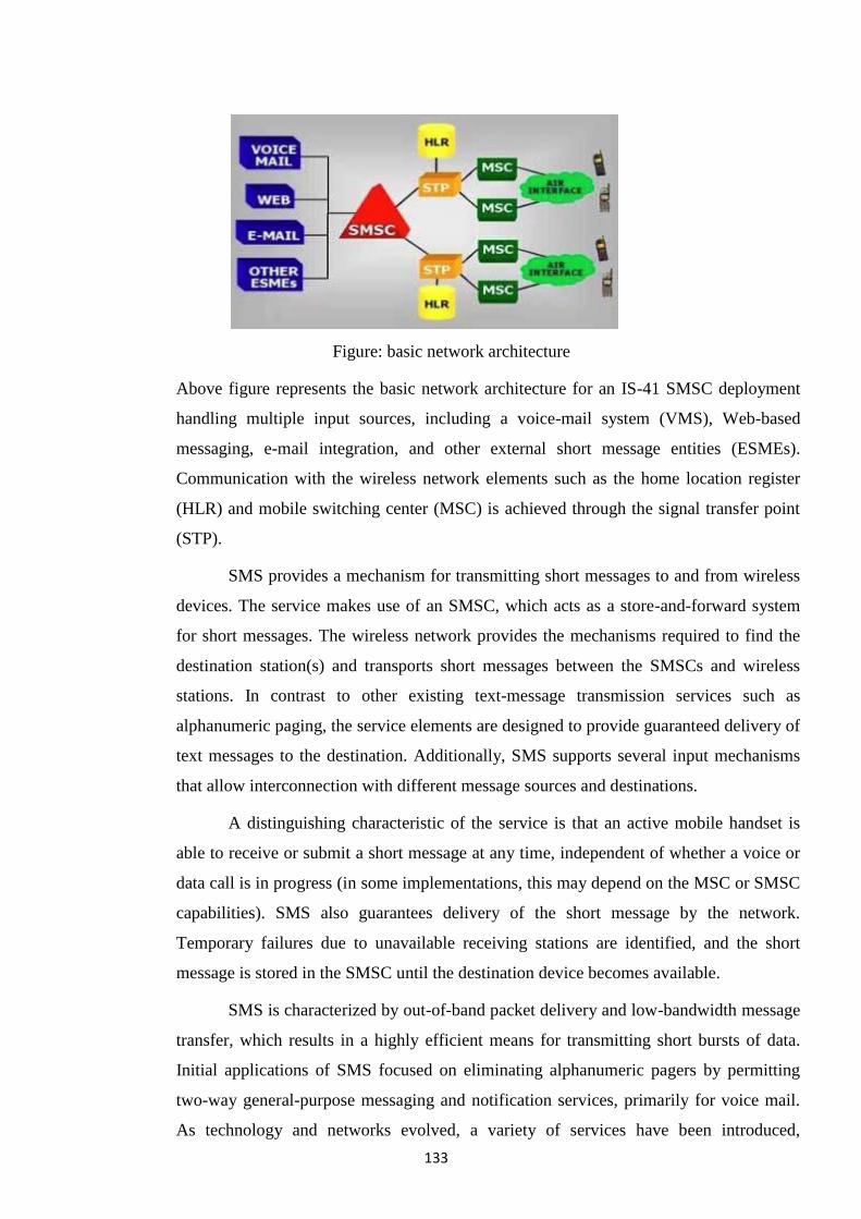
133
Figure: basic network architecture
Above figure represents the basic network architecture for an IS-41 SMSC deployment
handling multiple input sources, including a voice-mail system (VMS), Web-based
messaging, e-mail integration, and other external short message entities (ESMEs).
Communication with the wireless network elements such as the home location register
(HLR) and mobile switching center (MSC) is achieved through the signal transfer point
(STP).
SMS provides a mechanism for transmitting short messages to and from wireless
devices. The service makes use of an SMSC, which acts as a store-and-forward system
for short messages. The wireless network provides the mechanisms required to find the
destination station(s) and transports short messages between the SMSCs and wireless
stations. In contrast to other existing text-message transmission services such as
alphanumeric paging, the service elements are designed to provide guaranteed delivery of
text messages to the destination. Additionally, SMS supports several input mechanisms
that allow interconnection with different message sources and destinations.
A distinguishing characteristic of the service is that an active mobile handset is
able to receive or submit a short message at any time, independent of whether a voice or
data call is in progress (in some implementations, this may depend on the MSC or SMSC
capabilities). SMS also guarantees delivery of the short message by the network.
Temporary failures due to unavailable receiving stations are identified, and the short
message is stored in the SMSC until the destination device becomes available.
SMS is characterized by out-of-band packet delivery and low-bandwidth message
transfer, which results in a highly efficient means for transmitting short bursts of data.
Initial applications of SMS focused on eliminating alphanumeric pagers by permitting
two-way general-purpose messaging and notification services, primarily for voice mail.
As technology and networks evolved, a variety of services have been introduced,
134
including e-mail, fax, and paging integration, interactive banking, information services
such as stock quotes, and integration with Internet-based applications. Wireless data
applications include downloading of subscriber identity module (SIM) cards for
activation, debit, profile-editing purposes, wireless points of sale (POSs), and other field-
service applications such as automatic meter reading, remote sensing, and location-based
services. Additionally, integration with the Internet spurred the development of Web-
based messaging and other interactive applications such as instant messaging, gaming,
and chatting.
Benefits of SMS:
At a minimum, SMS benefits include the following:
• Delivery of notifications and alerts
• Guaranteed message delivery
• Reliable, low-cost communication mechanism for concise information
• Ability to screen messages and return calls in a selective way
• Increased subscriber productivity
More sophisticated functionality provides the following enhanced subscriber benefits:
• Delivery of messages to multiple subscribers at a time
• Ability to receive diverse information
• E-mail generation
• Creation of user groups
• Integration with other data and Internet-based applications
The benefits of SMS to the Service Provider are as follows:
• Ability to increment average revenue per user (due to increased number of calls
on wireless and wireline networks by leveraging the notification capabilities
of SMS)
• An alternative to alphanumeric paging services, which may replace or
complement an existing paging offer
• Ability to enable wireless data access for corporate users
• New revenue streams resulting from addition of value-added services such as e-
mail, voice mail, fax, and Web-based application integration, reminder
service, stock and currency quotes, and airline schedules
135
• Provision of key administrative services such as advice of charge, over-the-air
downloading, and over-the-air service provisioning
• Protection of important network resources (such as voice channels), due to
SMS‘ sparing use of the control and traffic channels
• Notification mechanisms for newer services such as those utilizing wireless
application protocol (WAP)
All of these benefits are attainable quickly, with modest incremental cost and
short payback periods, which make SMS an attractive investment for service
providers.
9.13 Architecture and Features of MMS (Multimedia Messaging Service)
Short Message Service (SMS) is a globally accepted wireless service that allows
mobile subscribers to send and receive alphanumeric messages of up to 140 bytes in
length. A distinguishing characteristic of the service is the guaranteed delivery of short
messages by the network via a store-and-forward mechanism. Temporary failures are
identified, and the short message is stored in the network until the destination becomes
available. Despite the enormous popularity of SMS, the content that can be transmitted is
limited to short text messages, ring tones, and small graphics.
Due to recent developments in wireless communications, building more flexible
and more capable messaging services has become the reality. The Multimedia Messaging
Service (MMS), a revolutionary successor to SMS, has emerged as the result of research
efforts primarily by the Third Generation Partnership Project (3GPP) and Open Mobile
Alliance (OMA). MMS will extend the revenue opportunities for network operators and
manufacturers, and lead to lower costs for customers.
To the end user MMS is very similar to SMS as it provides automatic and fast
delivery of multimedia messages (MMs) between capable phones and other devices.
However, there are important technical differences between SMS and MMS. MMS
supports richer content types such as text, graphics, music, video clips and more. The
MMS specifications do not mandate any specific content format for MMs. Instead the
MMs are encapsulated in a standard way; so that the recipient can identify those content
formats it does not support and handle them properly. The standard does not specify a
maximum size for an MM either in order to avoid the SMS message size limitation.
With the increasing size and volume of messages being transmitted, the fast and
robust delivery of messages becomes a challenging problem. As we will see later, the
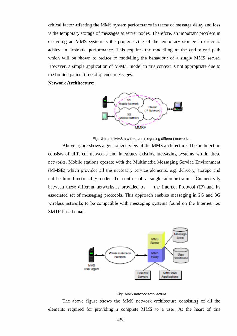
136
critical factor affecting the MMS system performance in terms of message delay and loss
is the temporary storage of messages at server nodes. Therefore, an important problem in
designing an MMS system is the proper sizing of the temporary storage in order to
achieve a desirable performance. This requires the modelling of the end-to-end path
which will be shown to reduce to modelling the behaviour of a single MMS server.
However, a simple application of M/M/1 model in this context is not appropriate due to
the limited patient time of queued messages.
Network Architecture:
Fig: General MMS architecture integrating different networks.
Above figure shows a generalized view of the MMS architecture. The architecture
consists of different networks and integrates existing messaging systems within these
networks. Mobile stations operate with the Multimedia Messaging Service Environment
(MMSE) which provides all the necessary service elements, e.g. delivery, storage and
notification functionality under the control of a single administration. Connectivity
between these different networks is provided by the Internet Protocol (IP) and its
associated set of messaging protocols. This approach enables messaging in 2G and 3G
wireless networks to be compatible with messaging systems found on the Internet, i.e.
SMTP-based email.
Fig: MMS network architecture
The above figure shows the MMS network architecture consisting of all the
elements required for providing a complete MMS to a user. At the heart of this
137
architecture is the MMS Relay/ Server (MMS-RS) which is responsible for storage and
reliable delivery of messages between possibly different messaging systems, akin to an
SMTP mail transfer agent (MTA). The MMSRS temporarily stores messages until they
are successfully delivered. The MMS-RS may be a single logical element or may be
separated into MMS Relay and MMS Server elements.
The MMS User Agent (MMS-UA) exists within a mobile station. This application
akin to an email reader application lets user view, compose and handle (e.g. submit,
receive, delete) multimedia messages. The retrieval of MMs from MMS-RS can be either
automatic or manual. In automatic mode, an MM is retrieved without user involvement.
In manual mode, the user is informed by a notification message and is allowed to make a
decision whether to download the MM or not.
The MMS-RS has access to several User Databases, e.g. user profile database,
subscription database and home location register (HLR). An optional feature of MMS is
the support of persistent network-based storage called an MMBox. The MMS-RS has
access to an MMBox in order to store, retrieve or delete messages. Depending on the
operator configuration, each subscriber may configure his MMBox to automatically store
incoming and submitted messages, or, manually request that specific messages be
persistently stored.
The MMS VAS Applications provide value added services to the MMS users.
Several External Servers may be included within or connected to an MMSE, e.g. E-Mail
server, SMS server and Fax server. The MMS-RS is responsible for providing
convergence functionality between External Servers and MMS-UAs. Thus mobile phone
users can use an MMS-RS to access email, multimedia attachments, SMS or faxes.
MMS OPERATION
A. Transmission of Multimedia Messages
1) Sending Messages: A user sends a message by having its MMS-UA submit the
message to its home MMS-RS. A message must have the address of the recipient
and a MIME content type. Several other parameters may be set for a message
including the desired time of expiry for the message and the message priority. Upon
reception of a message from an originator MMS-UA, the originator MMS-RS
assigns message identification to the message and sends this message identification
to the originator MMS-UA. If an MMBox is supported and enabled for the sender,
138
MMS-RS automatically stores a copy of the message into the sender MMBox, then
routes the message towards the recipients.
2) Receiving Messages: Upon reception of a message, the recipient MMS-RS
verifies the recipient profile and generates a notification to the recipient MMS-
UA. It also stores the message at least until one of the following events happens:
• the associated time of expiry is reached,
• the message is delivered,
• the recipient MMS-UA requests the message to be forwarded,
• the message is rejected.
If it has been requested, MMS-RS will also store the message in an MMBox, if
the MMBox is supported and enabled.
When the recipient MMS-UA receives a notification, it uses the message
reference in the notification to reject or retrieve the message, either immediately
or at a later time, either manually or automatically, as determined by the operator
configuration and user profile. If MMBoxes are supported, the MMS-UA may
request retrieval of a message from the user MMBox, based on a message
reference received from a previous MMBox operation.
9.14 The Features of EDGE System.
What is EDGE?
EDGE: Enhanced Data Rates for Global Evolution.
. EDGE is the radio technology that allows operators to increase both data speeds and
throughout capacity 3-4 times over GPRS.
. A major benefit of EDGE is that it enables existing TDMA carriers as well as GSM
carriers to offer 3G services while still realising lower costs due to higher efficiency and
higher data rates.
Features of EDGE
.600 M subscribers of GSM in over 170 countries, so offering GSM enhanced with
EDGE will enable full global roaming between the Americas, Europe and
Asia.
.EDGE was formerly called GSM384, because it allows data transmission speeds of 384
Kbps.
.This speed could be achieved when all eight timeslots are used.
. [The idea behind EDGE is to obtain even higher data rates on the current 200KHz GSM
carrier by changing the type of modulation used.
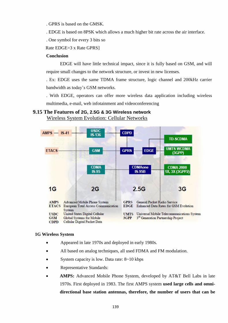
139
. GPRS is based on the GMSK.
. EDGE is based on 8PSK which allows a much higher bit rate across the air interface.
. One symbol for every 3 bits so
Rate EDGE=3 x Rate GPRS]
Conclusion
EDGE will have little technical impact, since it is fully based on GSM, and will
require small changes to the network structure, or invest in new licenses.
. Ex: EDGE uses the same TDMA frame structure, logic channel and 200kHz carrier
bandwidth as today‘s GSM networks.
. With EDGE, operators can offer more wireless data application including wireless
multimedia, e-mail, web infotainment and videoconferencing
9.15 The Features of 2G, 2.5G & 3G Wireless network
Wireless System Evolution: Cellular Networks
1G Wireless System
Appeared in late 1970s and deployed in early 1980s.
All based on analog techniques, all used FDMA and FM modulation.
System capacity is low. Data rate: 8~10 kbps
Representative Standards:
AMPS: Advanced Mobile Phone System, developed by AT&T Bell Labs in late
1970s. First deployed in 1983. The first AMPS system used large cells and omni-
directional base station antennas, therefore, the number of users that can be
140
supported was quite limited. AMPS is used all over the world and is esp. popular
in US, South America, China and Australia.
ETACS: European Total Access Communication Systems. Almost identical to
AMPS except that the channel bandwidth is scaled to25kHz instead of 30 kHz as in AMPS.
2G Wireless Systems: Characteristics
Deployed in mid 1990s, 2G wireless systems all use digital voice coding and digital
modulation.
Can provide advanced call capabilities and at least a 3-times increase in overall
system capacity.
Was designed before the widespread of the Internet, mainly supported voice-centric
services and limited date-service, like short messages, FAX,etc.
Date rate: on the order of 10 kbps
2G Wireless Systems: Representative Standards
GSM (Global Systems for Mobile communications)
A TDMA system, serves as the pan-European cellular service, provides a wide range of
network service, including phone service, FAX, short message service. Support
24.7kbpsdata rate.
USDC IS-136 (United States Digital Cellular)
A TDMA system which is compatible with AMPS, it supports more users (6 times) with
improved performance. It shares the same frequencies, frequency reuse plan and base
stations as AMPS. Provides access to VPN, supports short messages. Support 48.6kbpsdata
rate.
IS-95 (United States Digital Cellular Standard )
A CDMA standard also designed to be compatible with AMPS through using of
CDMA/AMPS dual mode phones and base stations. Capacity is 8~10 times that of AMPS.
Support 14.4kbpsdata rate.
2.5G Wireless System
Compared to 2G systems, 2.5G systems enables high speed data communications, provides
continuous connection to internet.
CDPD (Cellular Digital Packet Data), a data service for 1st and 2nd generation US cellular
systems without additional bandwidth requirement, packet channels are dynamically
assigned to idle voice channels. Support 48.6kbpsdata rate as in IS-136.
141
GPRS(General Packet Radio Service), based on GSM by allowing multipleslots of a GSM
radio channel be dedicated to an individual user, promises data rate from 56 kbps to
114kbps---continuous connection to the Internet for mobile phone and computer users,
easy access to VPN (Virtual Private Network).
EDGE (Enhanced Data Rates for GSM Evolution), providing 384kbpsrate by using
improved modulation (8-PSK instead of GMSK in GSM) and relaxed error control. Also
referred to as EGPRS.
CDMA one (IS-95B): Providing high speed data access on a common CDMA radio
channel by dedicating multiple orthogonal user channels for specific users or specific
purposes. Support 115.2kbps.
3G Wireless Systems: Features
Features:
High transmission rate and the support of multimedia services.
Multiple-megabit internet services, and simultaneous voice and data access with multiple
parties at the same time using a single mobile handset.
Date rate: around 2Mbps. Bandwidth: in the order of MHz
Seamless global roaming: wireless access from anywhere on the earth. Obviously, it will
include the satellite networks.
3GPP and 3GPP2
Worldwide standardization organizations established to gather global expertise,
participated by almost all the big companies.
3GPP: based on backward compatibility to GSM, IS-136, GPRS, EDGE etc.
3GPP2: based on backward compatibility to IS-95, and CDMAone.
3G Wireless Systems: Challenges
Impact of high transmission rate ---frequency selective fading
High transmission rate implies that the signal bandwidth is muchwider than the coherence
bandwidth of the channel, different frequencycomponents in the signal will experience
different fading characteristic.
Solution: Modulate each signal components onto a different subcarrier and send them over
the channel in parallel, so that each component will experience flat fading. => multicarrier
systems.
System capacity and user mobility
Enlarged capacity and higher transmission rate requires more efficient deployment of the
available bandwidth, which implies that the system needs to be reused more often.
Higher degree of frequency reuse implies more complex mobile management.
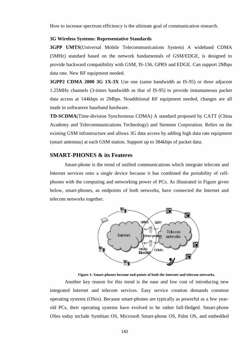
142
How to increase spectrum efficiency is the ultimate goal of communication research.
3G Wireless Systems: Representative Standards
3GPP UMTS(Universal Mobile Telecommunications System) A wideband CDMA
(5MHz) standard based on the network fundamentals of GSM/EDGE, is designed to
provide backward compatibility with GSM, IS-136, GPRS and EDGE. Can support 2Mbps
data rate. New RF equipment needed.
3GPP2 CDMA 2000 3G 1X-3X Use one (same bandwidth as IS-95) or three adjacent
1.25MHz channels (3-times bandwidth as that of IS-95) to provide instantaneous packet
data access at 144kbps or 2Mbps. Noadditional RF equipment needed, changes are all
made in softwareor baseband hardware.
TD-SCDMA(Time-division Synchronous CDMA) A standard proposed by CATT (China
Academy and Telecommunications Technology) and Siemens Corporation. Relies on the
existing GSM infrastructure and allows 3G data access by adding high data rate equipment
(smart antennas) at each GSM station. Support up to 384kbps of packet data.
SMART-PHONES & its Feateres
Smart-phone is the trend of unified communications which integrate telecom and
Internet services onto a single device because it has combined the portability of cell-
phones with the computing and networking power of PCs. As illustrated in Figure given
below, smart-phones, as endpoints of both networks, have connected the Internet and
telecom networks together.
Figure 1: Smart-phones become end-points of both the Internet and telecom networks.
Another key reason for this trend is the ease and low cost of introducing new
integrated Internet and telecom services. Easy service creation demands common
operating systems (OSes). Because smart-phones are typically as powerful as a few year-
old PCs, their operating systems have evolved to be rather full-fledged. Smart-phone
OSes today include Symbian OS, Microsoft Smart-phone OS, Palm OS, and embedded
143
Linux. Although the detailed design and functionality vary among these OS vendors, all
share the following features :
• Access to cellular network with various cellular standards such as GSM /CDMA and
UMTS.
• Access to the Internet with various network interfaces such as infrared, Bluetooth,
GPRS/CDMA1X, and 802.11; and use standard TCP/IP protocol stack to connect to the
Internet.
• Multi-tasking for running multiple applications simultaneously.
• Data synchronization with desktop PCs.
• Open APIs for application development.
While common OSes, open APIs, and sophisticated capabilities enable powerful
services, they also create common ground and opportunities for security breaches and
increase worm or virus spreading potentials. Given the PC-like nature of smart-phones
and the trend of full-fledged OSes, software vulnerabilities seem inevitable for their OSes
and applications. Moreover, with the Internet exposure, smart phones become ideal
targets for Internet worms or viruses since smart-phones are always on, and their user
population will likely exceed that of PCs,
9.17 MOBILE OPERATING SYSTEM
What is an Operating System? An OS is the most critical software element on any
running processor-based device. The OS manages the hardware and software resources
within a device and performs and manages basic tasks such as the recognition of input
from the device keyboard and generation of output to the device‘s screen. It also ensures
that different programs running at the same time do not interfere with each other. It is
responsible for the management of memory and for communication within the device.
OSs may be extended to add additional complexity and hence functionality to the code.
In the mobile world, the more complex OSs will contain, for example, UI (User
Interface) elements as these become increasingly important as the devices become more
complex. The OS is purposely hidden from the user who, as a general rule, will have no
direct interaction with it. It is, rather, a base onto which the applications required by the
user are loaded.
The OS is not only a key element in terms of the tasks it performs but the choice
of OS will constrain or enable the functionality of the end device in two key respects;
firstly that which is technically possible with any given OS and secondly that which is
available, i.e. what applications have been developed for that OS. The OS provides a
144
software platform on top of which other application programs can run. The application
programs have to be written for a particular OS so the choice of OS, therefore, determines
to a great extent the applications that can be offered on the end device. The OS also
provides a consistent interface for applications, regardless of the hardware it is loaded on.
Communication between the OS and the applications is done through an API
(Application Program Interface) which allows a software developer to write an
application for one device and have a high level of confidence that it will run on another
running the same OS.
Different types of Mobile operating systems
Mobile operating systems are talked in this section. This issue involves the most
popular operating systems such as: Symbian, Windows, Palm OS, BlackBerry, iOS,
Android, and Bada.
1. Symbian
Symbian is a mobile operating system designed for Smartphone originally
developed by Symbian Ltd. but currently maintained by Accenture. The Symbian
platform is the successor to Symbian OS and Nokia Series 60. The latest version,
Symbian ver.3, was officially released in Q4 2010 and first used in the Nokia N8. In
February 2011, Nokia announced that it would replace Symbian with Windows Phone as
the operating system on all of its future smartphones. This transition was completed in
October 2011, when Nokia announced its first line of Windows Phone 7.5 smartphones,
Nokia Lumia 710 and Nokia Lumia 800. Nokia committed to support its Symbian based
smartphones until 2016, by releasing further OS improvements, like Nokia Belle and
Nokia Belle FP1, and new devices, like the Nokia 808 Pure View. Microsoft Windows
CE (now officially known as Windows Embedded Compact and previously also known
as Windows Embedded CE, and sometimes abbreviated WinCE is an operating system
developed by Microsoft for embedded systems. Windows CE is a distinct operating
system and kernel, rather than a trimmed-down version of desktop Windows. It is not to
be confused with Windows Embedded Standard which is an NT-based componentized
version of desktop Microsoft Windows. Microsoft licenses Windows CE to OEMs and
device makers. The OEMs and device makers can modify and create their own user
interfaces and experiences, with Windows CE providing the technical foundation to do
so.
The current version of Windows Embedded Compact supports Intel x86 and compatibles,
MIPS, and ARM processors.
145
2. BlackBerry
BlackBerry is a line of phone devices developed and designed by Research In
Motion (RIM). The first BlackBerry smartphone was released in 1999. The latest
BlackBerry 7 devices were announced in the summer of 2011.
BlackBerry devices are smartphones, which are designed to function as personal
digital assistants, portable media players, internet browsers, gaming devices, cameras and
much more. They are primarily known for their ability to send and receive push email
and instant messages while maintaining a high level of security through on-device
message encryption. BlackBerry devices support a large variety of instant messaging
features, with the most popular being the proprietary BlackBerry Messenger service.
3. iOS
iOS (previously iPhone OS) is a mobile operating system developed and
distributed by Apple Inc. Originally released in 2007 for the iPhone and iPod Touch, it
has been extended to support other Apple devices such as the iPad and Apple TV. Unlike
Microsoft's Windows CE (Windows Phone) and Google's Android, Apple does not
license iOS for installation on non-Apple hardware. As of 2012 Apple's App Store
contained more than 700,000 iOS applications, which have collectively been downloaded
more than 30 billion times.
The user interface of iOS is based on the concept of direct manipulation, using
multi-touch gestures. Interface control elements consist of sliders, switches, and buttons.
The response to user input is immediate and provides a fluid interface. Interaction with
the OS includes gestures such as swipe, tap, pinch, and reverse pinch, all of which have
specific definitions within the context of the iOS operating system and its multi-touch
interface. Internal accelerometers are used by some applications to respond to shaking the
device (one common result is the undo command) or rotating it in three dimensions (one
common result is switching from portrait to landscape mode).
iOS is derived from OS X, with which it shares the Darwin foundation, and is therefore a
Unix operating system. iOS is Apple's mobile version of the OS X operating system used
on Apple computers. In iOS, there are four abstraction layers: the Core OS layer, the
Core Services layer, the Media layer, and the Cocoa Touch layer. The current version of
the operating system (iOS 5.1.1) dedicates 1-1.5 GB of the device's flash memory for the
system partition, using roughly 800 MB of that partition (varying by model) for iOS
itself.
146
4. Android
Android is a computing platform designed for use in some smart phones and other
devices. This technology, which is owned by Google, Inc., includes an operating system,
software, and applications. The operating system is based on Linux, which provides
advanced computer processing. Android technology is maintained and continually
developed by the Android Open Source Project (AOSP).
History of Android
Google purchased Android Inc., a 22-month-old Palo Alto, California, start-up in July
2005. Android Inc. was co-founded by Andy Rubin, maker of mobile device Danger Inc.
The purchase was key factor in Google's move into the wireless technology market. In
2008, Google introduced the HTC Dream as the first marketed phone to use Android
technology. Since that time, this platform use has expanded to other smart phones, tablet
computers, E-readers, eBooks, and other devices.
Android applications
Although Android technology is increasingly being used on a range of devices, the most
common hardware to use this platform is mobile phones. A large community of
developers regularly write applications (apps), including games, social networking, and
business modules, for Android smart phones. There are a wide range of free Android
apps, including games and productivity titles, and paid apps are even more common.
Android technology
— which is used by thousands of developers because it is freely available for download
— has given software developers the opportunity to sell their creations to a wide group of
consumers.
Programming for Android
Android technology is based on Java software applications. This technology requires the
use of a special software development kit (SDK) to create applications for an Android
device. The SDK is freely available for download from the Internet. For this reason, and
because it will work on multiple operating systems, many software developers prefer
Android technology over that used in other smart phones. Smart phones have evolved
into devices that use touch screens for navigation. Android technology provides specific
application programming interface (API) modules to developers that take advantage of
this. The touch screen enables the user to select and scroll through information with the
stroke of a finger.
What's so different in Android? The good news is for both the consumers and
developers. While consumers could enjoy a low-cost Smart phones running Android,
147
developers were given an unrestricted customization rights. From a developer's point of
view, Android has several advantages, as listed below:
• The entire Application framework can be reused and replaced by selective components
• Dalvik virtual machine enhances the power management systems (Learn about Dalvik
VM in the following subtitle)
• Support for 2D and 3D graphics (OpenGL ES 1.0), So lot of business for animation
developers.
• Reliable and enhanced data storage (using SQLite framework)
• Developers can create media common applications since it supports common media file
formats(MPEG, MPEG3, MPEG4, H.286, AAC, AMR, JPG, PNG, GIF and more) •
GSM, EDGE, 3G, HSCSD, Wi-Fi network applications support (Depends on hardware) •
Open source Web-Kit Engine-based web-browser
• GPS, Navigational compass, Touch-Unlock, and accelerometer applications support
(Depends on hardware)
• Androids development environment includes a device emulator, debugger,
performance profiling tool, and an Eclipse IDE plug-in
Reliability and security Android is a multi-process system, in which each application
(and parts of the system) runs in its own process. Most security between applications and
the system is enforced at the process level through standard Linux facilities, such as user
and group IDs that are assigned to applications. Additional finer-grained security features
are provided through a "permission" mechanism that enforces restrictions on the specific
operations that a particular process can perform, and per-URI permissions for granting
ad-hoc access to specific pieces of data.
5. Bada
Bada is an operating system for mobile devices such as smartphones and tablet
computers. It is developed by Samsung Electronics. Its name is derived from bada,
meaning "ocean" or "sea" in Korean. It ranges from mid-range to high-end
smartphones. To foster adoption of Bada OS, Samsung is reportedly considering
releasing the source code under an open-source license, and expanding device support to
include Smart TVs. Samsung announced in June 2012 it may merge Bada into the Tizen
project, but it is not confirmed. Samsung is using its own Bada operating system, in
parallel with Android OS and Windows Phone, for smartphones they develop.
All Bada-powered devices are branded under the Wave name; similar to how Samsung's
Android-powered devices are branded under the name Galaxy.
148
Bada, as Samsung defines it, is not an operating system itself, but a platform with a
kernel configurable architecture,
which allows using either a proprietary real-time operating system hybrid (RTOS) kernel
and Linux kernel.
According to copyrights displayed by Samsung Wave S8500, it uses code from
FreeBSD, NetBSD and OpenBSD.
Despite numerous suggestions, there is no known bada device to date that is running the
Linux kernel. Similarly, there is no evidence that Bada uses the same or similar graphics
stack as the Tizen OS, in particular EFL.
In architecture of Bada the device layer provides core functions such as graphics,
protocols, telephony and security.
The service layer provides more service-centric features such as SMS, mapping and in-
app-purchasing. To provide such features there is a so-called Bada Server. The top layer,
the framework layer provides an application programming interface (API) in C++ for
application developers to use.
Bada provides various UI controls to developers: It provides assorted basic UI controls
such as Listbox, Color Picker and Tab, has a web browser control based on the open-
source WebKit, and features Adobe Flash, supporting Flash 9, 10 or 11 (Flash Lite 4 with
ActionScript 3.0 support) in Bada 2.0. Both the WebKit and Flash can be embedded
inside native Bada applications. Bada supports OpenGL ES 2.0 3D graphics API and
offers interactive mapping with point of interest (POI) features, which can also be
embedded inside native applications. It supports pinch-to-zoom, tabbed browsing and
cut, copy, and paste features.
Bada supports many mechanisms to enhance interaction, which can be incorporated into
applications. These include various sensors such as motion sensing, vibration control,
face detection, accelerometer, magnetometer, tilt, Global Positioning System (GPS), and
multi-touch.
9.18 Principle of WLL.& PCS System
The WLL revolution is underway. WLL suppliers and operators are flocking to
emerging markets, using whatever available wireless and line interface technologies are
at hand to achieve fast time to market. Because there are no definitive WLL standards,
vendors are faced with a bewildering choice of fixed-access, mobile, and digital cordless
technologies.
Ultimately the appropriate protocol technology will depend on an array of
applications considerations, such as size and population density of the geographic area
149
(rural versus urban) and the service needs of the subscriber base (residential versus
business; POTS versus data access). In fact, there are many good reasons why different
wireless technologies will serve some applications better than others. The challenge for
WLL vendors is to identify the optimal wireless protocol for their unique application
needs, then reduce cost per subscriber through silicon and deliver integrated solutions to
the marketplace.
WLL will be implemented across five categories of wireless technology. They are
digital cellular, analog cellular, PCN/PCS, CT-2/DECT, and proprietary
implementations. Each of these technologies has a mix of strengths and weaknesses for
WLL applications.
Analog Cellular
Given its wide availability resulting from serving high mobility markets, there is
significant momentum to use analog cellular for WLL. There are currently three main
analog cellular system types operating in the world: advanced mobile phone system
(AMPS), nordic mobile telephone (NMT), and total access communications systems
(TACS). AMPS and its cousin narrowband advanced mobile phone system (NAMPS)
dominate the analog cellular market with 69% of subscribers, while TACS has 23% and
NMT has only 8%.
As a WLL platform, analog cellular has some limitations in regards to capacity
and functionality. Due to widespread deployment, analog cellular systems are expected to
be a major wireless platform for WLL, at least in the short term. Given its characteristics,
analog cellular is best suited to serve low-density to medium-density markets that don't
require landline-type features. Analog cellular is forecasted to account for 19% of the
wireless local loop subscribers in the year 2000.
Digital Cellular
These systems have seen rapid growth and are expected to outpace analog cellular
over the next few years. Major worldwide digital cellular standards include global system
for mobile communications (GSM), time division multiple access (TDMA), Hughes
enhanced TDMA (E-TDMA), and code division multiple access (CDMA). GSM
dominates the digital cellular market with 71% of subscribers.
Digital cellular is expected to play an important role in providing WLL. Like
analog cellular, digital cellular has the benefit of wide availability. Digital cellular can
support higher capacity subscribers than analog cellular, and it offers functionality that is
better suited to emulate capabilities of advanced wireline networks. Its disadvantage is
150
that it is not as scalable as analog cellular. It is forecasted that approximately one-third of
the installed wireless local loops will use digital cellular technology in the year 2000.
Although GSM currently dominates mobile digital cellular, there has been little
activity in using GSM as a WLL platform. Since GSM's architecture was designed to
handle international roaming, it carries a large amount of overhead that makes it
unwieldy and costly for WLL applications. In spite of these limitations, it is likely that
GSM WLL products will be developed over the next few years. CDMA appears to be the
standard best suited for WLL applications. CDMA employs a spread spectrum
modulation technique in which a wide range of frequency is used for transmission and
the system's low- power signal is spread across wide-frequency bands. It offers higher
capacity than the other digital standards (10 to 15 times greater than analog cellular),
relatively high-quality voice, and a high level of privacy. The main disadvantage of
CDMA is that it is only now beginning to be deployed on a wide scale.
Personal Communications Services (PCS)/Personal Communications
Network (PCN)
PCS/PCN incorporates elements of digital cellular and cordless standards as well
as newly developed RF protocols. Its purpose is to offer low-mobility wireless service
using low-power antennas and lightweight, inexpensive handsets. PCN is primarily seen
as a city communications system with far less range than cellular. PCS is a broad range
of individualized telecommunications services that let people or devices communicate
regardless of where they are. Some of the services include personal numbers assigned to
individuals rather than telephones, call completion regardless of locations ("find me"),
calls to the PCS customer that can be paid by either the caller or the receiver, and call
management services that give the called party greater control over incoming calls. It is
not clear which standards, if any, will dominate the WLL portion of PCS/PCN. The
candidate standards are CMDA, TDMA, GSM, personal access communication systems
(PACS), omnipoint CDMA, TDMA, upbanded CDMA, personal handyphone system
(PHS), and digital cordless telephone United States (DCT-U). These standards will
probably be used in combination to provide both WLL and high-mobility wireless
services.
PCS/PCN has the advantage of being designed specifically to provide WLL by public
wireless operators.
The main weakness of PCS/PCN is that it is not yet commercially available.
151
Cordless Telephones 2nd Generation/Digital European Cordless
Telephone (CT-2/DECT)
Cordless telephony was originally developed to provide wireless access within a
residence or business between a base station and a handset. Since the base station is still
hard-wired to the PSTN, this is not considered wireless local loop. For the purposes of
this study, DECT is considered WLL when a public network operator provides wireless
service directly to the user via this technology.
Although DECT does not appear to be ideally suited for rural or low-density
applications, it has some significant advantages in medium-density to high-density areas.
Cordless telephony has advantages in terms of scalability and functionality. As compared
to cellular technology, DECT is capable of carrying higher levels of traffic, provides
better voice quality, and can transmit data at higher rates. The microcell architecture of
DECT allows it to be deployed in smaller increments that more closely match the
subscriber demand, with reduced initial capital requirements.
Proprietary Implementations
Proprietary WLL systems encompass a variety of technologies and
configurations. These systems are considered proprietary because they are not available
on public wireless networks and are typically customized for a specific application. They
generally do not provide mobility. This makes proprietary technology most effective for
applications that cannot cost effectively or time effectively be reached by landline
alternatives. Proprietary systems are, therefore, positioned to pro
9.19 Mobile Radio Propagation
There are two basic ways of transmitting an electro-magnetic (EM) signal,
through a guided medium or through an unguided medium. Guided mediums such as
coaxial cables and fiber optic cables, are far less hostile toward the information carrying
EM signal than the wireless or the unguided medium. It presents challenges and
conditions which are unique for this kind of transmissions. A signal, as it travels through
the wireless channel, undergoes many kinds of propagation effects such as
– reflection
– diffraction
– scattering, due to the presence of buildings, mountains and other such obstructions.
Reflection occurs when the EM waves impinge on objects which are much greater than
the wavelength of the travelling wave.
152
Diffraction is a phenomena occurring when the wave interacts with a surface having
sharp irregularities.
Scattering occurs when the medium through the wave is travelling contains objects
which are much smaller than the wavelength of the EM wave.
These varied phenomena‘s lead to large scale and small scale propagation losses. Due to
the inherent randomness associated with such channels they are best described with the
help of statistical models. Models which predict the mean signal strength for arbitrary
transmitter receiver distances are termed as large scale propagation models.
Log-distance Path Loss Model
– average received signal power decreases logarithmically with distance
• The average path loss
Where PL = Path Loss, d0 = Reference distance & d = measured distance
The value of n varies with propagation environments. The value of n is 2 for free
space. The value of n varies from 4 to 6 for obstruction of building, and 3 to 5 for urban
scenarios. The important factor is to select the correct reference distance d0. For large cell
area it is 1 Km, while for micro-cell system it varies from 10m-1m.
Limitations:
Surrounding environmental clutter may be different for two locations having the same
transmitter to receiver separation. Moreover it does not account for the shadowing
effects.


![ACM Transactions on Sensor Networks (TOSN), …...wireless camera network. Categories and Subject Descriptors: C.2.2 [Computer-Communication Networks]: Network Protocols–-Protocol](https://img.pdfslide.us/doc/110x75/5fc30ee43cde4c0fa20fea56/acm-transactions-on-sensor-networks-tosn-wireless-camera-network-categories.jpg)