Embed Size (px)
Citation preview

SUBJECT
WIRELESS NETWORKS SESSION 7 Radio resource management (RRM) Medium
Access Control (MAC)
SESSION 7
1
Radio Resource Management"
Radio resource management (RRM) is the system level control of co-channel
interference and other radio transmission characteristics in wireless
communication systems, for example cellular networks, wireless
networks and broadcasting systems.[1][2] RRM involves strategies and algorithms
for controlling parameters such as transmit power, user allocation, beamforming,
data rates, handover criteria, modulation scheme, error coding scheme, etc.
The objective is to utilize the limited radio-frequency spectrum resources and
radio network infrastructure as efficiently as possible.
RRM concerns multi-user and multi-cell network capacity issues, rather than the
point-to-point channel capacity. Traditional telecommunications research and
education often dwell upon channel coding and source coding with a single
user in mind, although it may not be possible to achieve the maximum channel
capacity when several users and adjacent base stations share the same
frequency channel. Efficient dynamic RRM schemes may increase the system
spectral efficiency by an order of magnitude, which often is considerably more
than what is possible by introducing advanced channel coding and source
coding schemes. RRM is especially important in systems limited by co-channel
interference rather than by noise, for example cellular systems and broadcast
networks homogeneously covering large areas, and wireless networks consisting
of many adjacentaccess points that may reuse the same channel frequencies.
The cost for deploying a wireless network is normally dominated by base station
sites (real estate costs, planning, maintenance, distribution network, energy,
etc.) and sometimes also by frequency license fees. The objective of radio
resource management is therefore typically to maximize the system spectral
efficiency in bit/s/Hz/area unit orErlang/MHz/site, under some kind of user
fairness constraint, for example, that the grade of service should be above a
certain level. The latter involves covering a certain area and
avoiding outage due to co-channel interference, noise, attenuation caused by
path losses, fading caused by shadowing and multipath, Doppler shift and other
forms ofdistortion. The grade of service is also affected by blocking due
to admission control, scheduling starvation or inability to guarantee quality of
service that is requested by the users.
While classical radio resource managements primarily considered the allocation
of time and frequency resources (with fixed spatial reuse patterns), recent multi-
user MIMOtechniques enables adaptive resource management also in the
spatial domain.[3] In cellular networks, this means that the fractional frequency

2
reuse in the GSM standard has been replaced by a universal frequency reuse
in LTE standard.
Some chief information officers and information technology managers are
reluctant to deploy wireless LANs. Among their concerns are reliability,
availability, performance, and deployment. Each of these concerns can be
directly addressed through the radio resource management techniques used in
a new generation of wireless LAN equipment. The new capabilities include
dynamic channel assignment, dynamic power control, and load sharing.
Changing from the relatively static radio resource management techniques
generally in use today to dynamic methods like those highlighted in this article
helps to increase the capacity and improve the performance of large-scale
wireless LANs.
MAC address
Medium Access Control (MAC)
The Medium Access Control (MAC) protocol is used to provide the data link
layer of the Ethernet LAN system. The MAC protocol encapsulates a SDU
(payload data) by adding a 14 byte header (Protocol Control Information (PCI))
before the data and appending an integrity checksum, The checksum is a 4-
byte (32-bit) Cyclic Redundancy Check (CRC) after the data. The entire frame is
preceded by a small idle period (the minimum inter-frame gap, 9.6
microsecond (µS)) and a 8 byte preamble (including the start of frame
delimiter).
Preamble
The purpose of the idle time before transmission starts is to allow a small time
interval for the receiver electronics in each of the nodes to settle after
completion of the previous frame. A node starts transmission by sending an 8
byte (64 bit) preamble sequence. This consists of 62 alternating 1's and 0's
followed by the pattern 11. Strictly speaking the last byte which finished with the
'11' is known as the "Start of Frame Delimiter". When encoded using Manchester
encoding, at 10 Mbps, the 62 alternating bits produce a 10 MHz square wave
(one complete cycle each bit period).

3
The purpose of the preamble is to allow time for the receiver in each node to
achieve lock of the receiver Digital Phase Lock Loop which is used to
synchronise the receive data clock to the transmit data clock. At the point
when the first bit of the preamble is received, each receiver may be in an
arbitrary state (i.e. have an arbitrary phase for its local clock). During the course
of the preamble it learns the correct phase, but in so doing it may miss (or gain)
a number of bits. A special pattern (11), is therefore used to mark the last two
bits of the preamble. When this is received, the Ethernet receive interface starts
collecting the bits into bytes for processing by the MAC layer. It also confirms the
polarity of the transition representing a '1' bit to the receiver (as a check in case
this has been inverted).
Header
MAC encapsulation of a packet of data
The header consists of three parts:
A 6-byte destination address, which specifies either a single recipient
node (unicast mode), a group of recipient nodes (multicast mode), or the
set of all recipient nodes (broadcast mode).
A 6-byte source address, which is set to the sender's globally unique node
address. This may be used by the network layer protocol to identify the
sender, but usually other mechanisms are used (e.g.arp). Its main function
is to allow address learning which may be used to configure the filter
tables in a bridge.
A 2-byte type field, which provides a Service Access Point (SAP) to identify
the type of protocol being carried (e.g. the values 0x0800 is used to
4
identify the IP network protocol, other values are used to indicate other
network layer protocols). In the case of IEEE 802.3 LLC, this may also be
used to indicate the length of the data part. Th type field is also be used
to indicate when a Tag field is added to a frame.
CRC
The final field in an Ethernet MAC frame is called a Cyclic Redundancy Check
(sometimes also known as a Frame Check Sequence). A 32-bit CRC provides
error detection in the case where line errors (or transmission collisions in Ethernet)
result in corruption of the MAC frame. Any frame with an invalid CRC is
discarded by the MAC receiver without further processing. The MAC protocol
does not provide any indication that a frame has been discarded due to an
invalid CRC.
The link layer CRC therefore protects the frame from corruption while being
transmitted over the physical mediuym (cable). A new CRC is added if the
packet is forwarded by the router on another Ethernet link. While the packet is
being processed by the router the packet data is not protected by the CRC.
Router processing errors must be detected by network or transport-layer
checksums.
Inter Frame Gap
After transmission of each frame, a transmitter must wait for a period of 9.6
microseconds (at 10 Mbps) to allow the signal to propagate through the
receiver electronics at the destination. This period of time is known as the Inter-
Frame Gap (IFG). While every transmitter must wait for this time between
sending frames, receivers do not necessarily see a "silent" period of 9.6
microseconds. The way in which repeaters operate is such that they may
reduce the IFG between the frames which they regenerate.
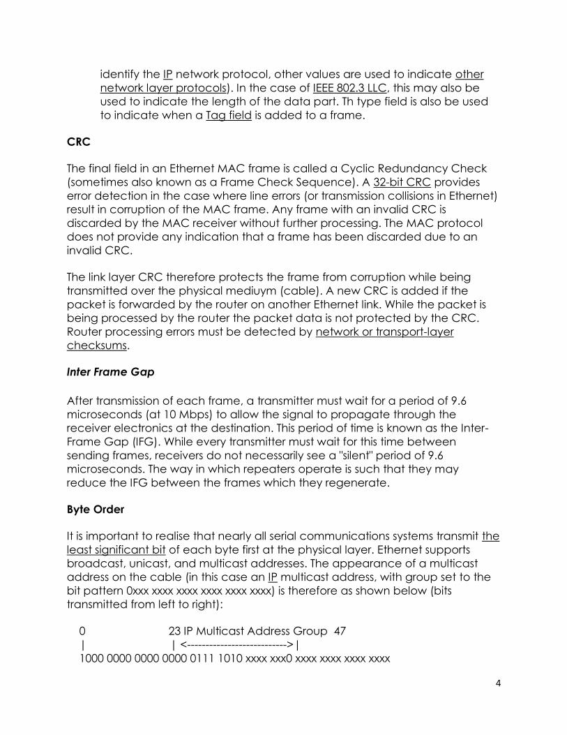
Byte Order
It is important to realise that nearly all serial communications systems transmit the
least significant bit of each byte first at the physical layer. Ethernet supports
broadcast, unicast, and multicast addresses. The appearance of a multicast
address on the cable (in this case an IP multicast address, with group set to the
bit pattern 0xxx xxxx xxxx xxxx xxxx xxxx) is therefore as shown below (bits
transmitted from left to right):
0 23 IP Multicast Address Group 47
| | <--------------------------->|
1000 0000 0000 0000 0111 1010 xxxx xxx0 xxxx xxxx xxxx xxxx

5
| |
Multicast Bit 0 = Internet Multicast
1 = Assigned for other uses
However, when the same frame is stored in the memory of a computer, the bits
are ordered such that the least significant bit of each byte is stored in the right
most position (the bits are transmitted right-to-left within bytes, bytes transmitted
left-to-right):
0 23 47
| | |
0000 0001 0000 0000 0101 1110 0xxx xxxx xxxx xxxx xxxx xxxx
| <--------------------------->
Multicast Bit IP Multicast Address Group
CSMA /CD
The Carrier Sense Multiple Access (CSMA) with Collision Detection (CD) protocol
is used to control access to the shared Ethernet medium. A switched network
(e.g. Fast Ethernet) may use a full duplex mode giving access to the full link
speed when used between directly connected NICs, Switch to NIC cables, or
Switch to Switch cables.
Receiver Processing Algorithm
Runt Frame
Any frame which is received and which is less than 64 bytes is illegal, and is
called a "runt". In most cases, such frames arise from a collision, and while they
indicate an illegal reception, they may be observed on correctly functioning
networks. A receiver must discard all runt frames.
6
Giant Frame
Any frame which is received and which is greater than the maximum frame size,
is called a "giant". In theory, the jabber control circuit in the transceiver should
prevent any node from generating such a frame, but certain failures in the
physical layer may also give rise to over-sized Ethernet frames. Like runts, giants
are discarded by an Ethernet receiver.
Jumbo Frame
Some modern Gigabit Ethernet NICs support frames that are larger than the
traditional 1500 bytes specified by the IEEE. This new mode requires support by
both ends of the link to support Jumbo Frames.Path MTU Discovery is required for
a router to utilise this feature, since there is no other way for a router to
determine that all systems on the end-to-end path will support these larger sized
frames.
A Misaligned Frame
Any frame which does not contain an integral number of received bytes (bytes)
is also illegal. A receiver has no way of knowing which bits are legal, and how to
compute the CRC-32 of the frame. Such frames are therefore also discarded by
the Ethernet receiver.
Other Issues
The Ethernet standard dictates a minimum size of frame, which requires at least
46 bytes of data to be present in every MAC frame. If the network layer wishes
to send less than 46 bytes of data the MAC protocol adds sufficient number of
zero bytes (0x00, is also known as null padding characters) to satisfy this
requirement. The maximum size of data which may be carried in a MAC frame
using Ethernet is 1500 bytes (this is known as the MTU in IP).
A protocol known as the "Address Resolution Protocol" (arp) is used to identify
the MAC source address of remote computers when IP is used over
an Ethernet LAN.
Exception to the Rule
An extension to Ethernet, known as IEEE 802.1p allows for frames to carry a tag.
The tag value adds an extra level of PCI to the Ethernet frame header. This
increases the size of the total MAC frame when the tag is used. A side effect of
this is that NICs and network devices designed to support this extension require a
modification to the jabber detection circuit.

7
A media access control address (MAC address) is a unique identifier assigned
to network interfaces for communications on the physical network segment.
MAC addresses are used as a network address for most IEEE 802 network
technologies, including Ethernet and WiFi. Logically, MAC addresses are used in
the media access control protocol sublayer of the OSI reference model.
MAC addresses are most often assigned by the manufacturer of a network
interface controller (NIC) and are stored in its hardware, such as the card's read-
only memory or some other firmware mechanism. If assigned by the
manufacturer, a MAC address usually encodes the manufacturer's registered
identification number and may be referred to as the burned-in address (BIA). It
may also be known as an Ethernet hardware address (EHA), hardware
address or physical address. This can be contrasted to a programmed address,
where the host device issues commands to the NIC to use an arbitrary address.
A network node may have multiple NICs and each NIC must have a unique
MAC address.
MAC addresses are formed according to the rules of one of three numbering
name spaces managed by the Institute of Electrical and Electronics
Engineers (IEEE): MAC-48, EUI-48, and EUI-64. The IEEE claims trademarks on the
names EUI-48 and EUI-64, in which EUI is an abbreviation for Extended Unique
Identifier.
Contents
1 Notational conventions
2 Address details
o 2.1 Individual address block
3 Usage in hosts
4 Spying
5 Usage in switches
6 Bit-reversed notation
7 See also
8 References
9 External links
Notational conventions[
The standard (IEEE 802) format for printing MAC-48 addresses in human-friendly
form is six groups of two hexadecimal digits, separated by hyphens (-) or colons
(:), in transmission order (e.g. 01-23-45-67-89-ab or 01:23:45:67:89:ab ). This form
is also commonly used for EUI-64. Another convention used by networking
equipment uses three groups of four hexadecimal digits separated by dots (.)
(e.g. 0123.4567.89ab ), again in transmission order.[1]

8
Address details[
The original IEEE 802 MAC address comes from the original Xerox Ethernet
addressing scheme.[2]This 48-bit address space contains potentially 248 or
281,474,976,710,656 possible MAC addresses.
All three numbering systems use the same format and differ only in the length of
the identifier. Addresses can either be universally administered
addresses or locally administered addresses. A universally administered address
is uniquely assigned to a device by its manufacturer. The first threeoctets (in
transmission order) identify the organization that issued the identifier and are
known as theOrganizationally Unique Identifier (OUI).[3] The following three
(MAC-48 and EUI-48) or five (EUI-64) octets are assigned by that organization in
nearly any manner they please, subject to the constraint of uniqueness. The IEEE
has a target lifetime of 100 years for applications using MAC-48 space, but
encourages adoption of EUI-64s instead.[3] A locally administered address is
assigned to a device by a network administrator, overriding the burned-in
address. Locally administered addresses do not contain OUIs.
Universally administered and locally administered addresses are distinguished by
setting the second-least-significant bit of the most significant byte of the
address. This bit is also referred to as the U/L bit, short for Universal/Local, which
identifies how the address is administered. If the bit is 0, the address is universally
administered. If it is 1, the address is locally administered. In the example address
06-00-00-00-00-00 the most significant byte is 06 (hex), the binary form of which is
9
00000110, where the second-least-significant bit is 1. Therefore, it is a locally
administered address.[4] Consequently, this bit is 0 in all OUIs.
If the least significant bit of the most significant octet of an address is set to 0
(zero), the frame is meant to reach only one receiving NIC.[5] This type of
transmission is calledunicast. A unicast frame is transmitted to all nodes within
the collision domain, which typically ends at the nearest network
switch or router. A switch will forward a unicast frame through all of its ports
(except for the port that originated the frame) if the switch has no knowledge of
which port leads to that MAC address, or just to the proper port if it does have
knowledge.[6][ Only the node with the matching hardware MAC address will
accept the frame; network frames with non-matching MAC-addresses are
ignored, unless the device is in promiscuous mode.
If the least significant bit of the most significant address octet is set to 1, the
frame will still be sent only once; however, NICs will choose to accept it based
on criteria other than the matching of a MAC address: for example, based on a
configurable list of accepted multicast MAC addresses. This is
called multicast addressing.
The following technologies use the MAC-48 identifier format:
Ethernet
802.11 wireless networks
Bluetooth
IEEE 802.5 token ring
most other IEEE 802 networks
Fiber Distributed Data Interface (FDDI)
Asynchronous Transfer Mode (ATM), switched virtual connections only, as
part of an NSAP address
Fibre Channel and Serial Attached SCSI (as part of a World Wide Name)
The ITU-T G.hn standard, which provides a way to create a high-speed (up to
1 gigabit/s) local area network using existing home wiring (power lines,
phone lines and coaxial cables). The G.hn Application Protocol
Convergence (APC) layer accepts Ethernet frames that use the MAC-48
format and encapsulates them into G.hn Medium Access Control Service
Data Units (MSDUs).
Every device that connects to an IEEE 802 network (such as Ethernet and WiFi)
has a MAC-48 address.[7] Common consumer devices to use MAC-48 include
every PC, smartphone or tablet computer.
The distinction between EUI-48 and MAC-48 identifiers is purely nominal: MAC-48
is used for network hardware; EUI-48 is used to identify other devices and
software. (Thus, by definition, an EUI-48 is not in fact a "MAC address", although it
10
is syntactically indistinguishable from one and assigned from the same
numbering space.)
The IEEE now considers the label MAC-48 to be an obsolete term, previously
used to refer to a specific type of EUI-48 identifier used to address hardware
interfaces within existing 802-based networking applications, and thus not to be
used in the future. Instead, the proprietary term EUI-48 should be used for this
purpose.
The EUI-48 is expected to have its address space exhausted by the year 2100.[3]
EUI-64 identifiers are used in:
FireWire
IPv6 (Modified EUI-64 as the least-significant 64 bits of a unicast network
address or link-local address when stateless autoconfiguration is used)
ZigBee / 802.15.4 / 6LoWPAN wireless personal-area networks
The IEEE has built in several special address types to allow more than
one network interface card to be addressed at one time:
Packets sent to the broadcast address, all one bits, are received by all
stations on a local area network. In hexadecimal the broadcast address
would be FF:FF:FF:FF:FF:FF. A broadcast frame is flooded and is forwarded to
and accepted by all other nodes.
Packets sent to a multicast address are received by all stations on a LAN that
have been configured to receive packets sent to that address.
Functional addresses identify one or more Token Ring NICs that provide a
particular service, defined in IEEE 802.5.
These are all examples of group addresses, as opposed to individual addresses;
the least significant bit of the first octet of a MAC address distinguishes individual
addresses from group addresses. That bit is set to 0 in individual addresses and
set to 1 in group addresses. Group addresses, like individual addresses, can be
universally administered or locally administered.
In addition, the EUI-64 numbering system encompasses both MAC-48 and EUI-48
identifiers by a simple translation mechanism.[8] To convert a MAC-48 into an EUI-
64, copy the OUI, append the two octets FF-FF and then copy the organization-
specified extension identifier. To convert an EUI-48 into an EUI-64, the same
process is used, but the sequence inserted is FF-FE. In both cases, the process
can be trivially reversed when necessary. Organizations issuing EUI-64s are
cautioned against issuing identifiers that could be confused with these forms.
The IEEE policy is to discourage new uses of 48-bit identifiers in favor of the EUI-64
system.
IPv6 — one of the most prominent standards that uses a Modified EUI-64 — treats
MAC-48 as EUI-48 instead (as it is chosen from the same address pool) and

11
toggles the U/L bit (as this makes it easier to type locally assigned IPv6 addresses
based on the Modified EUI-64). This results in extending MAC addresses (such as
IEEE 802 MAC address) to Modified EUI-64 using only FF-FE (and never FF-FF) and
with the U/L bit inverted.
Individual address block
An Individual Address Block is a 24-bit OUI managed by the IEEE Registration
Authority, followed by 12 IEEE-provided bits (identifying the organization), and 12
bits for the owner to assign to individual devices. An IAB is ideal for organizations
requiring fewer than 4097 unique 48-bit numbers (EUI-48).[10]
Usage in hosts[
Although intended to be a permanent and globally unique identification, it is
possible to change the MAC address on most modern hardware. Changing
MAC addresses is necessary in network virtualization. It can also be used in the
process of exploiting security vulnerabilities. This is called MAC spoofing.
A host cannot determine from the MAC address of another host whether that
host is on the same link (network segment) as the sending host, or on a network
segment bridged to that network segment.
In IP networks, the MAC address of an interface can be queried given the IP
address using the Address Resolution Protocol (ARP) for Internet Protocol Version
4 (IPv4) or theNeighbor Discovery Protocol (NDP) for IPv6. In this way, ARP or NDP
is used to translate IP addresses (OSI layer 3) into Ethernet MAC addresses (OSI
layer 2). On broadcast networks, such as Ethernet, the MAC address uniquely
identifies each node on that segment and allows frames to be marked for
specific hosts. It thus forms the basis of most of the link layer (OSI Layer 2)
networking upon which upper layer protocols rely to produce complex,
functioning networks.
Spying[edit]
According to Edward Snowden, the National Security Agency has a system that
tracks the movements of everyone in a city by monitoring the MAC addresses of
their electronic devices.[11]