Embed Size (px)
Citation preview
SERVING THE DIE & MOLD BUILDING INDUSTRIES
Revised 1/92 © 1990 Superior Die Set Corp.
DIE SET PRODUCT LINEDIE SET PRODUCT LINEDIE SET PRODUCT LINEDIE SET PRODUCT LINEDIE SET PRODUCT LINE
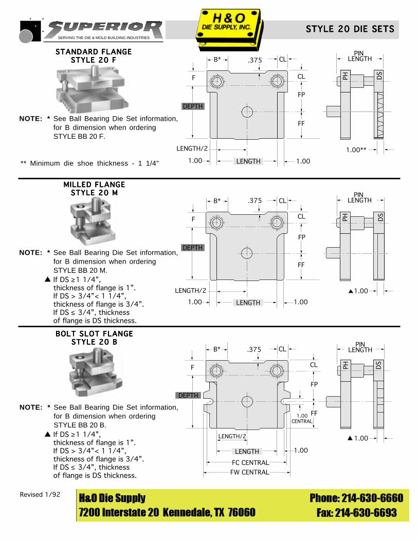
STYLE 20 - Two pin, square back withshank. Available in Standard Flange, MilledFlange and Bolt Slot Flange types.
STYLE 35 - Two centered pin type.
STYLE 50 - Three corner pin type.
WEAR PLATE DIE SETS - Heavy dutysets. Available with bosses and heel blocks.in U, L, and V System configurations.
LAMINATION DIE SETS - The best preci-sion die set manufactured to tight tolerancesrequired for high volume operations with sus-tainable accuracy.
PLATE CAPABILITIES - Raw plate inven-tories, torch cutting, stress relieving, shotblasting, Blanchard or surface grinding,machining and inspection.
FORTAL PLATE MATERIAL -Lightweight, high strength easy tomachine aluminum alloy material forall die sets. This stable material hashigher strength than 1020 steel.
STYLE 25 - Two back pin type.
STYLE 45 - Two diagonal pin type.
STYLE 75 - Four pin type.
MULTI-SLIDE DIE SETS
BALL BEARING DIE SETS - High speeddesign for all above styles of Friction BallBearing die sets.
BOSS DIE SETS - Heavy dutydesign for Friction or Ball Bearingdie sets.
SERVING THE DIE & MOLD BUILDING INDUSTRIES
NOTE: * See Ball Bearing Die Set information,for B dimension when ordering STYLE BB 20 B.
NOTE: * See Ball Bearing Die Set information,for B dimension when orderingSTYLE BB 20 M.
NOTE: * See Ball Bearing Die Set information,for B dimension when orderingSTYLE BB 20 F.
Revised 1/92 © 1990 Superior Die Set Corp.
STYLE 20 DIE SETSSTYLE 20 DIE SETSSTYLE 20 DIE SETSSTYLE 20 DIE SETSSTYLE 20 DIE SETS
F
.375B*
LENGTH/2
DEPTH
LENGTH 1.001.00
FF
FP
CL
CL
PH
PIN LENGTH
1.00**
DS
STANDARD FLANGESTANDARD FLANGESTANDARD FLANGESTANDARD FLANGESTANDARD FLANGESTYLE 20 FSTYLE 20 FSTYLE 20 FSTYLE 20 FSTYLE 20 F
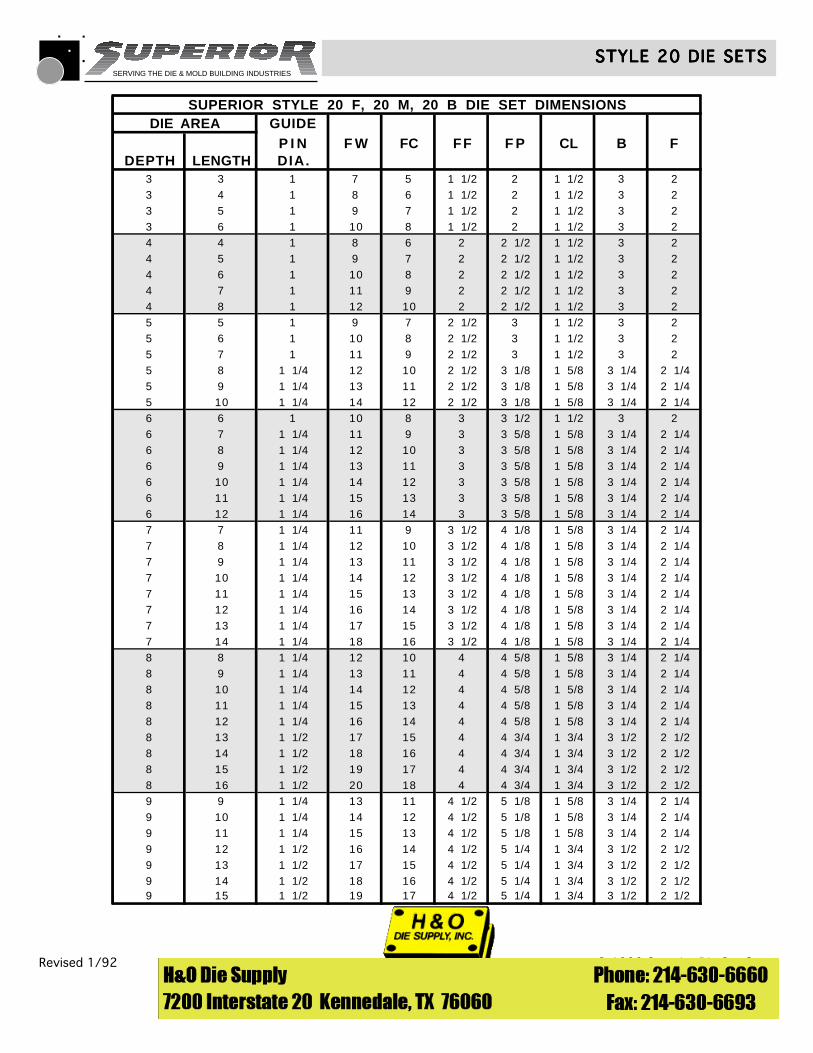
BOLT SLOT FLANGEBOLT SLOT FLANGEBOLT SLOT FLANGEBOLT SLOT FLANGEBOLT SLOT FLANGESTYLE 20 BSTYLE 20 BSTYLE 20 BSTYLE 20 BSTYLE 20 B
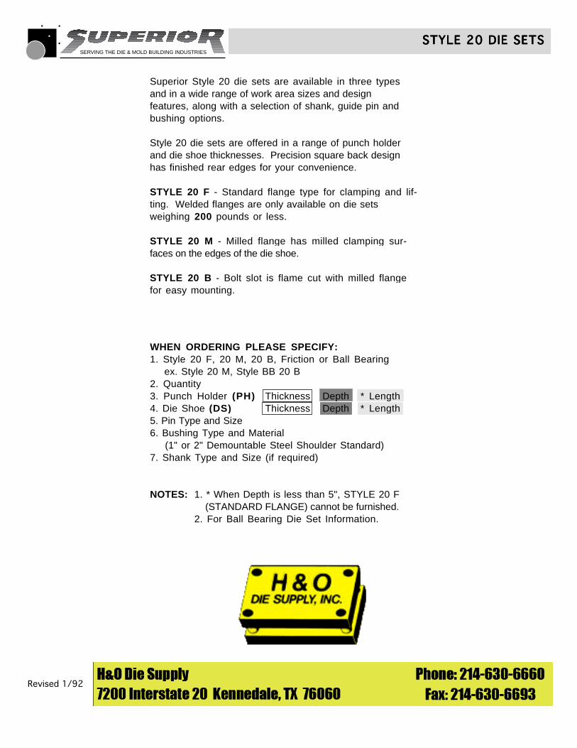
MILLED FLANGEMILLED FLANGEMILLED FLANGEMILLED FLANGEMILLED FLANGESTYLE 20 MSTYLE 20 MSTYLE 20 MSTYLE 20 MSTYLE 20 M
F
.375B*
LENGTH/2
DEPTH
LENGTH 1.001.00
FF
FP
CL
CL
PH DS
PIN LENGTH
1.00
** Minimum die shoe thickness - 1 1/4"
F
.375B*
LENGTH/2
DEPTH
LENGTH
FW CENTRAL
FC CENTRAL
1.00
FF
FP
CL
CLPH D
S
PINLENGTH
1.00
1.00CENTRAL
If DS ≥1 1/4”,thickness of flange is 1”.If DS > 3/4”< 1 1/4”,thickness of flange is 3/4”.If DS ≤ 3/4”, thicknessof flange is DS thickness.
If DS ≥1 1/4”,thickness of flange is 1”.If DS > 3/4”< 1 1/4”,thickness of flange is 3/4”.If DS ≤ 3/4”, thicknessof flange is DS thickness.
▲
▲
SERVING THE DIE & MOLD BUILDING INDUSTRIES
Revised 1/92 © 1990 Superior Die Set Corp.
STYLE 20 DIE SETSSTYLE 20 DIE SETSSTYLE 20 DIE SETSSTYLE 20 DIE SETSSTYLE 20 DIE SETS
Superior Style 20 die sets are available in three typesand in a wide range of work area sizes and designfeatures, along with a selection of shank, guide pin andbushing options.
Style 20 die sets are offered in a range of punch holderand die shoe thicknesses. Precision square back designhas finished rear edges for your convenience.
STYLE 20 F - Standard flange type for clamping and lif-ting. Welded flanges are only available on die setsweighing 200 pounds or less.
STYLE 20 M - Milled flange has milled clamping sur-faces on the edges of the die shoe.
STYLE 20 B - Bolt slot is flame cut with milled flangefor easy mounting.
WHEN ORDERING PLEASE SPECIFY:1. Style 20 F, 20 M, 20 B, Friction or Ball Bearing ex. Style 20 M, Style BB 20 B2. Quantity3. Punch Holder (PH) Thickness Depth * Length4. Die Shoe (DS) Thickness Depth * Length5. Pin Type and Size6. Bushing Type and Material (1" or 2" Demountable Steel Shoulder Standard)7. Shank Type and Size (if required)
NOTES: 1. * When Depth is less than 5", STYLE 20 F (STANDARD FLANGE) cannot be furnished.2. For Ball Bearing Die Set Information.
SERVING THE DIE & MOLD BUILDING INDUSTRIES
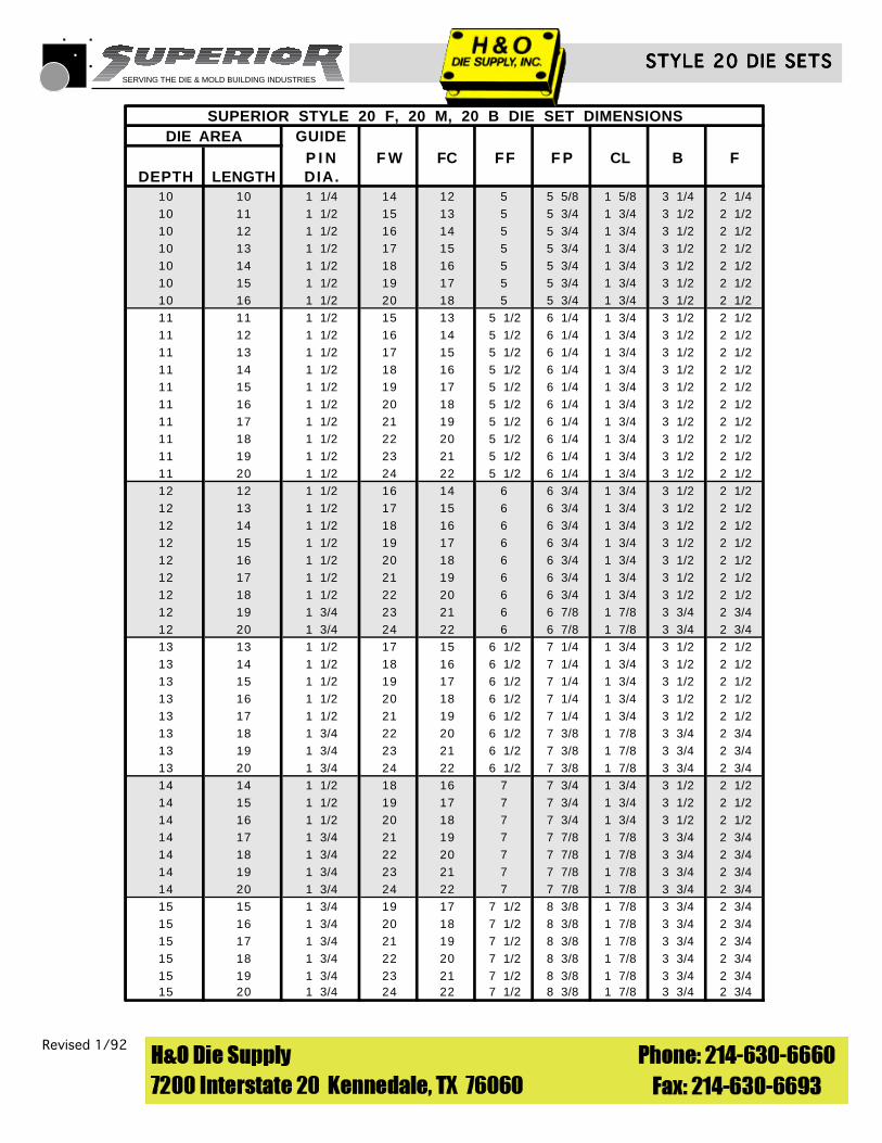
SUPERIOR STYLE 20 F, 20 M, 20 B DIE SET DIMENSIONSDIE AREA GUIDE
P I N F W FC FF F P CL B FDEPTH LENGTH DIA.
3 3 1 7 5 1 1/2 2 1 1/2 3 23 4 1 8 6 1 1/2 2 1 1/2 3 23 5 1 9 7 1 1/2 2 1 1/2 3 23 6 1 10 8 1 1/2 2 1 1/2 3 24 4 1 8 6 2 2 1/2 1 1/2 3 24 5 1 9 7 2 2 1/2 1 1/2 3 24 6 1 10 8 2 2 1/2 1 1/2 3 24 7 1 11 9 2 2 1/2 1 1/2 3 24 8 1 12 10 2 2 1/2 1 1/2 3 25 5 1 9 7 2 1/2 3 1 1/2 3 25 6 1 10 8 2 1/2 3 1 1/2 3 25 7 1 11 9 2 1/2 3 1 1/2 3 25 8 1 1/4 12 10 2 1/2 3 1/8 1 5/8 3 1/4 2 1/45 9 1 1/4 13 11 2 1/2 3 1/8 1 5/8 3 1/4 2 1/45 10 1 1/4 14 12 2 1/2 3 1/8 1 5/8 3 1/4 2 1/46 6 1 10 8 3 3 1/2 1 1/2 3 26 7 1 1/4 11 9 3 3 5/8 1 5/8 3 1/4 2 1/46 8 1 1/4 12 10 3 3 5/8 1 5/8 3 1/4 2 1/46 9 1 1/4 13 11 3 3 5/8 1 5/8 3 1/4 2 1/46 10 1 1/4 14 12 3 3 5/8 1 5/8 3 1/4 2 1/46 11 1 1/4 15 13 3 3 5/8 1 5/8 3 1/4 2 1/46 12 1 1/4 16 14 3 3 5/8 1 5/8 3 1/4 2 1/47 7 1 1/4 11 9 3 1/2 4 1/8 1 5/8 3 1/4 2 1/47 8 1 1/4 12 10 3 1/2 4 1/8 1 5/8 3 1/4 2 1/47 9 1 1/4 13 11 3 1/2 4 1/8 1 5/8 3 1/4 2 1/47 10 1 1/4 14 12 3 1/2 4 1/8 1 5/8 3 1/4 2 1/47 11 1 1/4 15 13 3 1/2 4 1/8 1 5/8 3 1/4 2 1/47 12 1 1/4 16 14 3 1/2 4 1/8 1 5/8 3 1/4 2 1/47 13 1 1/4 17 15 3 1/2 4 1/8 1 5/8 3 1/4 2 1/47 14 1 1/4 18 16 3 1/2 4 1/8 1 5/8 3 1/4 2 1/48 8 1 1/4 12 10 4 4 5/8 1 5/8 3 1/4 2 1/48 9 1 1/4 13 11 4 4 5/8 1 5/8 3 1/4 2 1/48 10 1 1/4 14 12 4 4 5/8 1 5/8 3 1/4 2 1/48 11 1 1/4 15 13 4 4 5/8 1 5/8 3 1/4 2 1/48 12 1 1/4 16 14 4 4 5/8 1 5/8 3 1/4 2 1/48 13 1 1/2 17 15 4 4 3/4 1 3/4 3 1/2 2 1/28 14 1 1/2 18 16 4 4 3/4 1 3/4 3 1/2 2 1/28 15 1 1/2 19 17 4 4 3/4 1 3/4 3 1/2 2 1/28 16 1 1/2 20 18 4 4 3/4 1 3/4 3 1/2 2 1/29 9 1 1/4 13 11 4 1/2 5 1/8 1 5/8 3 1/4 2 1/49 10 1 1/4 14 12 4 1/2 5 1/8 1 5/8 3 1/4 2 1/49 11 1 1/4 15 13 4 1/2 5 1/8 1 5/8 3 1/4 2 1/49 12 1 1/2 16 14 4 1/2 5 1/4 1 3/4 3 1/2 2 1/29 13 1 1/2 17 15 4 1/2 5 1/4 1 3/4 3 1/2 2 1/29 14 1 1/2 18 16 4 1/2 5 1/4 1 3/4 3 1/2 2 1/29 15 1 1/2 19 17 4 1/2 5 1/4 1 3/4 3 1/2 2 1/2
Revised 1/92 © 1990 Superior Die Set Corp.
STYLE 20 DIE SETSSTYLE 20 DIE SETSSTYLE 20 DIE SETSSTYLE 20 DIE SETSSTYLE 20 DIE SETS
SERVING THE DIE & MOLD BUILDING INDUSTRIES
Revised 1/92 © 1990 Superior Die Set Corp.
STYLE 20 DIE SETSSTYLE 20 DIE SETSSTYLE 20 DIE SETSSTYLE 20 DIE SETSSTYLE 20 DIE SETS
SUPERIOR STYLE 20 F, 20 M, 20 B DIE SET DIMENSIONSDIE AREA GUIDE
P I N F W FC FF F P CL B FDEPTH LENGTH DIA.
10 10 1 1/4 14 12 5 5 5/8 1 5/8 3 1/4 2 1/410 11 1 1/2 15 13 5 5 3/4 1 3/4 3 1/2 2 1/210 12 1 1/2 16 14 5 5 3/4 1 3/4 3 1/2 2 1/210 13 1 1/2 17 15 5 5 3/4 1 3/4 3 1/2 2 1/210 14 1 1/2 18 16 5 5 3/4 1 3/4 3 1/2 2 1/210 15 1 1/2 19 17 5 5 3/4 1 3/4 3 1/2 2 1/210 16 1 1/2 20 18 5 5 3/4 1 3/4 3 1/2 2 1/211 11 1 1/2 15 13 5 1/2 6 1/4 1 3/4 3 1/2 2 1/211 12 1 1/2 16 14 5 1/2 6 1/4 1 3/4 3 1/2 2 1/211 13 1 1/2 17 15 5 1/2 6 1/4 1 3/4 3 1/2 2 1/211 14 1 1/2 18 16 5 1/2 6 1/4 1 3/4 3 1/2 2 1/211 15 1 1/2 19 17 5 1/2 6 1/4 1 3/4 3 1/2 2 1/211 16 1 1/2 20 18 5 1/2 6 1/4 1 3/4 3 1/2 2 1/211 17 1 1/2 21 19 5 1/2 6 1/4 1 3/4 3 1/2 2 1/211 18 1 1/2 22 20 5 1/2 6 1/4 1 3/4 3 1/2 2 1/211 19 1 1/2 23 21 5 1/2 6 1/4 1 3/4 3 1/2 2 1/211 20 1 1/2 24 22 5 1/2 6 1/4 1 3/4 3 1/2 2 1/212 12 1 1/2 16 14 6 6 3/4 1 3/4 3 1/2 2 1/212 13 1 1/2 17 15 6 6 3/4 1 3/4 3 1/2 2 1/212 14 1 1/2 18 16 6 6 3/4 1 3/4 3 1/2 2 1/212 15 1 1/2 19 17 6 6 3/4 1 3/4 3 1/2 2 1/212 16 1 1/2 20 18 6 6 3/4 1 3/4 3 1/2 2 1/212 17 1 1/2 21 19 6 6 3/4 1 3/4 3 1/2 2 1/212 18 1 1/2 22 20 6 6 3/4 1 3/4 3 1/2 2 1/212 19 1 3/4 23 21 6 6 7/8 1 7/8 3 3/4 2 3/412 20 1 3/4 24 22 6 6 7/8 1 7/8 3 3/4 2 3/413 13 1 1/2 17 15 6 1/2 7 1/4 1 3/4 3 1/2 2 1/213 14 1 1/2 18 16 6 1/2 7 1/4 1 3/4 3 1/2 2 1/213 15 1 1/2 19 17 6 1/2 7 1/4 1 3/4 3 1/2 2 1/213 16 1 1/2 20 18 6 1/2 7 1/4 1 3/4 3 1/2 2 1/213 17 1 1/2 21 19 6 1/2 7 1/4 1 3/4 3 1/2 2 1/213 18 1 3/4 22 20 6 1/2 7 3/8 1 7/8 3 3/4 2 3/413 19 1 3/4 23 21 6 1/2 7 3/8 1 7/8 3 3/4 2 3/413 20 1 3/4 24 22 6 1/2 7 3/8 1 7/8 3 3/4 2 3/414 14 1 1/2 18 16 7 7 3/4 1 3/4 3 1/2 2 1/214 15 1 1/2 19 17 7 7 3/4 1 3/4 3 1/2 2 1/214 16 1 1/2 20 18 7 7 3/4 1 3/4 3 1/2 2 1/214 17 1 3/4 21 19 7 7 7/8 1 7/8 3 3/4 2 3/414 18 1 3/4 22 20 7 7 7/8 1 7/8 3 3/4 2 3/414 19 1 3/4 23 21 7 7 7/8 1 7/8 3 3/4 2 3/414 20 1 3/4 24 22 7 7 7/8 1 7/8 3 3/4 2 3/415 15 1 3/4 19 17 7 1/2 8 3/8 1 7/8 3 3/4 2 3/415 16 1 3/4 20 18 7 1/2 8 3/8 1 7/8 3 3/4 2 3/415 17 1 3/4 21 19 7 1/2 8 3/8 1 7/8 3 3/4 2 3/415 18 1 3/4 22 20 7 1/2 8 3/8 1 7/8 3 3/4 2 3/415 19 1 3/4 23 21 7 1/2 8 3/8 1 7/8 3 3/4 2 3/415 20 1 3/4 24 22 7 1/2 8 3/8 1 7/8 3 3/4 2 3/4
SERVING THE DIE & MOLD BUILDING INDUSTRIES
LENGTH/2
DEPTH
LENGTH
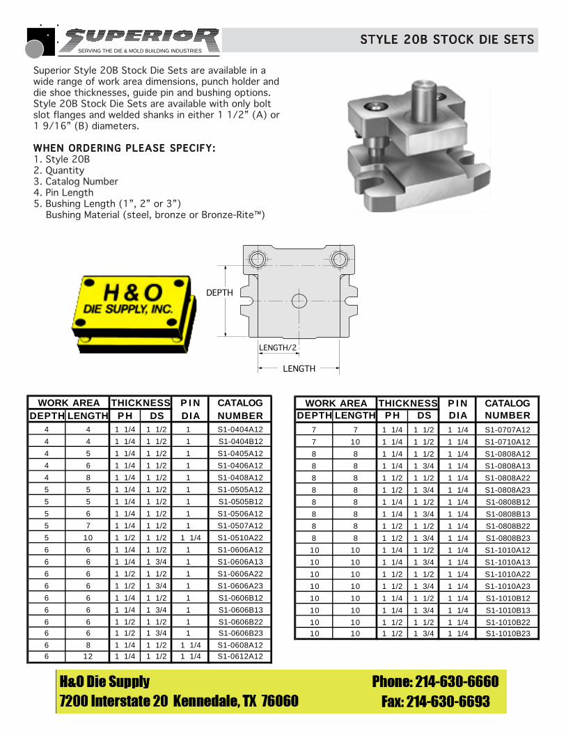
Superior Style 20B Stock Die Sets are available in awide range of work area dimensions, punch holder anddie shoe thicknesses, guide pin and bushing options.Style 20B Stock Die Sets are available with only boltslot flanges and welded shanks in either 1 1/2” (A) or1 9/16” (B) diameters.
WHEN ORDERING PLEASE SPECIFY:WHEN ORDERING PLEASE SPECIFY:WHEN ORDERING PLEASE SPECIFY:WHEN ORDERING PLEASE SPECIFY:WHEN ORDERING PLEASE SPECIFY:1. Style 20B2. Quantity3. Catalog Number4. Pin Length5. Bushing Length (1”, 2” or 3”) Bushing Material (steel, bronze or Bronze-Rite™)
STYLE 20B STOCK DIE SETSSTYLE 20B STOCK DIE SETSSTYLE 20B STOCK DIE SETSSTYLE 20B STOCK DIE SETSSTYLE 20B STOCK DIE SETS
WORK AREA THICKNESS P I N CATALOGDEPTH LENGTH P H DS DIA NUMBER
7 7 1 1/4 1 1/2 1 1/4 S1-0707A12
7 10 1 1/4 1 1/2 1 1/4 S1-0710A12
8 8 1 1/4 1 1/2 1 1/4 S1-0808A12
8 8 1 1/4 1 3/4 1 1/4 S1-0808A13
8 8 1 1/2 1 1/2 1 1/4 S1-0808A22
8 8 1 1/2 1 3/4 1 1/4 S1-0808A23
8 8 1 1/4 1 1/2 1 1/4 S1-0808B12
8 8 1 1/4 1 3/4 1 1/4 S1-0808B13
8 8 1 1/2 1 1/2 1 1/4 S1-0808B22
8 8 1 1/2 1 3/4 1 1/4 S1-0808B23
10 10 1 1/4 1 1/2 1 1/4 S1-1010A12
10 10 1 1/4 1 3/4 1 1/4 S1-1010A13
10 10 1 1/2 1 1/2 1 1/4 S1-1010A22
10 10 1 1/2 1 3/4 1 1/4 S1-1010A23
10 10 1 1/4 1 1/2 1 1/4 S1-1010B12
10 10 1 1/4 1 3/4 1 1/4 S1-1010B13
10 10 1 1/2 1 1/2 1 1/4 S1-1010B2210 10 1 1/2 1 3/4 1 1/4 S1-1010B23
WORK AREA THICKNESS P I N CATALOGDEPTH LENGTH P H DS DIA NUMBER
4 4 1 1/4 1 1/2 1 S1-0404A12
4 4 1 1/4 1 1/2 1 S1-0404B12
4 5 1 1/4 1 1/2 1 S1-0405A12
4 6 1 1/4 1 1/2 1 S1-0406A12
4 8 1 1/4 1 1/2 1 S1-0408A12
5 5 1 1/4 1 1/2 1 S1-0505A12
5 5 1 1/4 1 1/2 1 S1-0505B12
5 6 1 1/4 1 1/2 1 S1-0506A12
5 7 1 1/4 1 1/2 1 S1-0507A12
5 10 1 1/2 1 1/2 1 1/4 S1-0510A22
6 6 1 1/4 1 1/2 1 S1-0606A12
6 6 1 1/4 1 3/4 1 S1-0606A13
6 6 1 1/2 1 1/2 1 S1-0606A22
6 6 1 1/2 1 3/4 1 S1-0606A23
6 6 1 1/4 1 1/2 1 S1-0606B12
6 6 1 1/4 1 3/4 1 S1-0606B13
6 6 1 1/2 1 1/2 1 S1-0606B226 6 1 1/2 1 3/4 1 S1-0606B23
6 8 1 1/4 1 1/2 1 1/4 S1-0608A126 12 1 1/4 1 1/2 1 1/4 S1-0612A12
SERVING THE DIE & MOLD BUILDING INDUSTRIES
Thickness Depth Length
Thickness Depth Length
WHEN ORDERING PLEASE SPECIFY:WHEN ORDERING PLEASE SPECIFY:WHEN ORDERING PLEASE SPECIFY:WHEN ORDERING PLEASE SPECIFY:WHEN ORDERING PLEASE SPECIFY:1. Style 21 M, 21 B, Friction or Ball Bearing ex. Style 21 M, Style BB 21 B
2. Quantity
3. Punch Holder (PH)(PH)(PH)(PH)(PH)
4. Die Shoe (DS)(DS)(DS)(DS)(DS)
5. Pin Type and Size
6. Bushing Type and Material
7. Shank Type and Size (if required)
DEPTH
DEPTH/2
LENGTH
LENGTH/2
PUNCH HOLDER
SHANK LOCATION
VIEW B-B
DIE SHOE
LENGTH
DEPTH/2
DEPTH
VIEW A-A
SHANKOPTIONAL
B A
B
A
PH DS
SEENOTE
BELOW
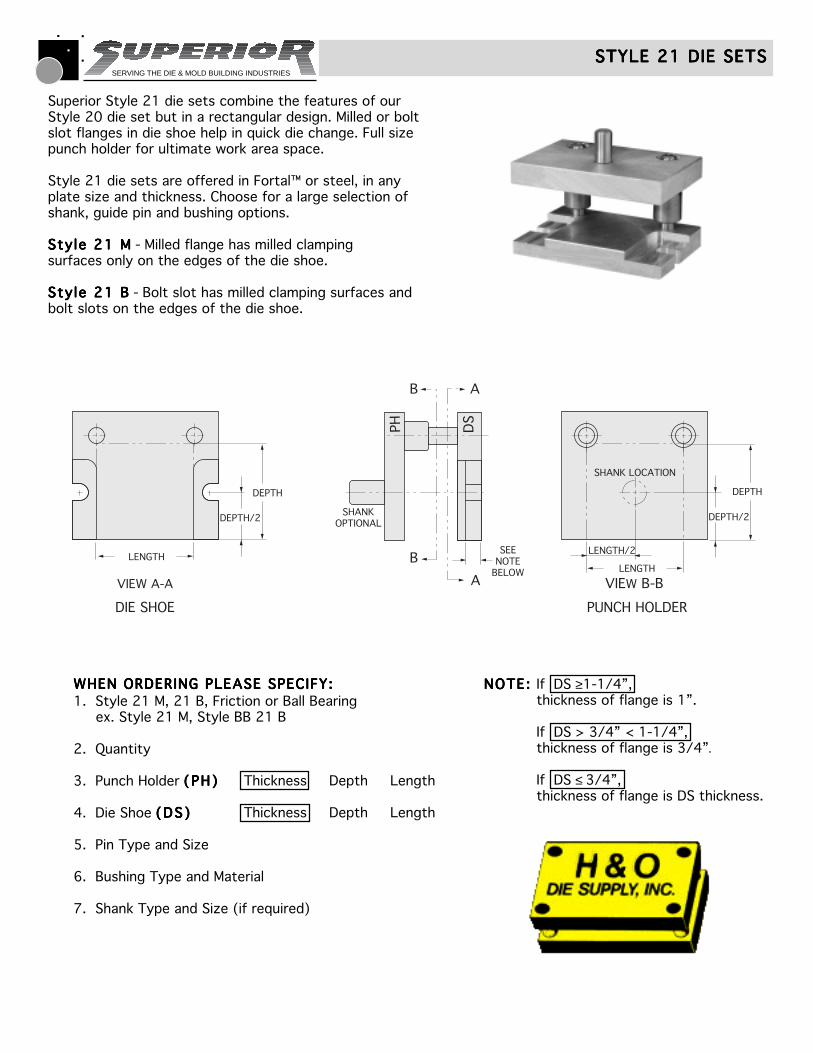
Superior Style 21 die sets combine the features of ourStyle 20 die set but in a rectangular design. Milled or boltslot flanges in die shoe help in quick die change. Full sizepunch holder for ultimate work area space.
Style 21 die sets are offered in Fortal™ or steel, in anyplate size and thickness. Choose for a large selection ofshank, guide pin and bushing options.
Style 21 MStyle 21 MStyle 21 MStyle 21 MStyle 21 M - Milled flange has milled clampingsurfaces only on the edges of the die shoe.
Style 21 BStyle 21 BStyle 21 BStyle 21 BStyle 21 B - Bolt slot has milled clamping surfaces andbolt slots on the edges of the die shoe.
If DS ≥1-1/4”,thickness of flange is 1”.
If DS > 3/4” < 1-1/4”,thickness of flange is 3/4”.
If DS ≤ 3/4”,thickness of flange is DS thickness.
NOTE:NOTE:NOTE:NOTE:NOTE:
STYLE 21 DIE SETSSTYLE 21 DIE SETSSTYLE 21 DIE SETSSTYLE 21 DIE SETSSTYLE 21 DIE SETS
SERVING THE DIE & MOLD BUILDING INDUSTRIES
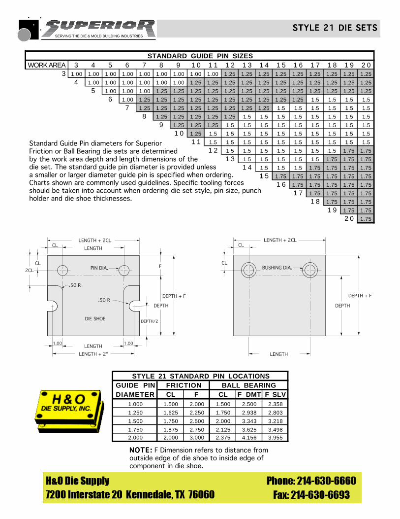
STANDARD GUIDE PIN SIZESWORK AREA 3 4 5 6 7 8 9 1 0 1 1 1 2 1 3 1 4 1 5 1 6 1 7 1 8 1 9 2 0
3 1.00 1.00 1.00 1.00 1.00 1.00 1.00 1.00 1.00 1.25 1.25 1.25 1.25 1.25 1.25 1.25 1.25 1.25
4 1.00 1.00 1.00 1.00 1.00 1.00 1.25 1.25 1.25 1.25 1.25 1.25 1.25 1.25 1.25 1.25 1.25
5 1.00 1.00 1.00 1.25 1.25 1.25 1.25 1.25 1.25 1.25 1.25 1.25 1.25 1.25 1.25 1.25
6 1.00 1.25 1.25 1.25 1.25 1.25 1.25 1.25 1.25 1.25 1.25 1.5 1.5 1.5 1.5
7 1.25 1.25 1.25 1.25 1.25 1.25 1.25 1.25 1.5 1.5 1.5 1.5 1.5 1.5
8 1.25 1.25 1.25 1.25 1.25 1.5 1.5 1.5 1.5 1.5 1.5 1.5 1.5
9 1.25 1.25 1.25 1.5 1.5 1.5 1.5 1.5 1.5 1.5 1.5 1.5
1 0 1.25 1.5 1.5 1.5 1.5 1.5 1.5 1.5 1.5 1.5 1.5
1 1 1.5 1.5 1.5 1.5 1.5 1.5 1.5 1.5 1.5 1.5
1 2 1.5 1.5 1.5 1.5 1.5 1.5 1.5 1.75 1.75
1 3 1.5 1.5 1.5 1.5 1.5 1.75 1.75 1.75
1 4 1.5 1.5 1.5 1.75 1.75 1.75 1.75
1 5 1.75 1.75 1.75 1.75 1.75 1.75
1 6 1.75 1.75 1.75 1.75 1.75
1 7 1.75 1.75 1.75 1.75
1 8 1.75 1.75 1.75
1 9 1.75 1.75
2 0 1.75
CL
DEPTH + F
DEPTH
LENGTH
CL
BUSHING DIA.
LENGTH + 2CL
LENGTH
LENGTH + 2CL
1.00 1.00
CL
2CL
CL
DEPTH/2
DEPTH
DEPTH + F
DIE SHOE
.50 R
.50 R
PIN DIA. F
LENGTH
LENGTH + 2"
Standard Guide Pin diameters for SuperiorFriction or Ball Bearing die sets are determinedby the work area depth and length dimensions of thedie set. The standard guide pin diameter is provided unlessa smaller or larger diameter guide pin is specified when ordering.Charts shown are commonly used guidelines. Specific tooling forcesshould be taken into account when ordering die set style, pin size, punchholder and die shoe thicknesses.
STYLE 21 DIE SETSSTYLE 21 DIE SETSSTYLE 21 DIE SETSSTYLE 21 DIE SETSSTYLE 21 DIE SETS
STYLE 21 STANDARD PIN LOCATIONSGUIDE PIN FRICTION BALL BEARINGDIAMETER CL F CL F DMT F SLV
1.000 1.500 2.000 1.500 2.500 2.358
1.250 1.625 2.250 1.750 2.938 2.803
1.500 1.750 2.500 2.000 3.343 3.218
1.750 1.875 2.750 2.125 3.625 3.4982.000 2.000 3.000 2.375 4.156 3.955
NOTE:NOTE:NOTE:NOTE:NOTE: F Dimension refers to distance fromoutside edge of die shoe to inside edge ofcomponent in die shoe.
SERVING THE DIE & MOLD BUILDING INDUSTRIES
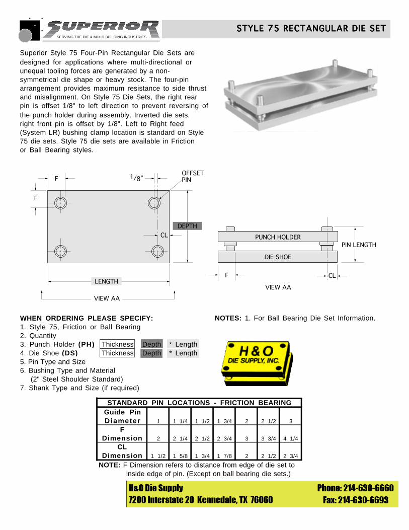
STANDARD PIN LOCATIONS - FRICTION BEARINGGuide PinDiameter 1 1 1/4 1 1/2 1 3/4 2 2 1/2 3
FDimension 2 2 1/4 2 1/2 2 3/4 3 3 3/4 4 1/4
CLDimension 1 1/2 1 5/8 1 3/4 1 7/8 2 2 1/2 2 3/4
NOTE: F Dimension refers to distance from edge of die set to inside edge of pin. (Except on ball bearing die sets.)
NOTES: 1. For Ball Bearing Die Set Information.
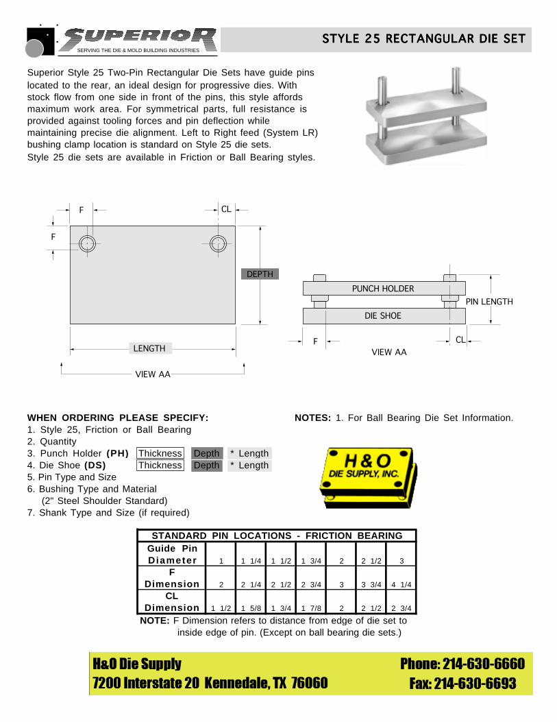
Superior Style 25 Two-Pin Rectangular Die Sets have guide pinslocated to the rear, an ideal design for progressive dies. Withstock flow from one side in front of the pins, this style affordsmaximum work area. For symmetrical parts, full resistance isprovided against tooling forces and pin deflection whilemaintaining precise die alignment. Left to Right feed (System LR)bushing clamp location is standard on Style 25 die sets.Style 25 die sets are available in Friction or Ball Bearing styles.
© 1990 Superior Die Set Corp.
STYLE 25 RECTANGULAR DIE SETSTYLE 25 RECTANGULAR DIE SETSTYLE 25 RECTANGULAR DIE SETSTYLE 25 RECTANGULAR DIE SETSTYLE 25 RECTANGULAR DIE SET
F
F CL
CL
DEPTH
VIEW AA
VIEW AALENGTH
PUNCH HOLDER
DIE SHOE
F
PIN LENGTH
WHEN ORDERING PLEASE SPECIFY:1. Style 25, Friction or Ball Bearing2. Quantity3. Punch Holder (PH) Thickness Depth * Length4. Die Shoe (DS) Thickness Depth * Length5. Pin Type and Size6. Bushing Type and Material (2" Steel Shoulder Standard)7. Shank Type and Size (if required)
SERVING THE DIE & MOLD BUILDING INDUSTRIES
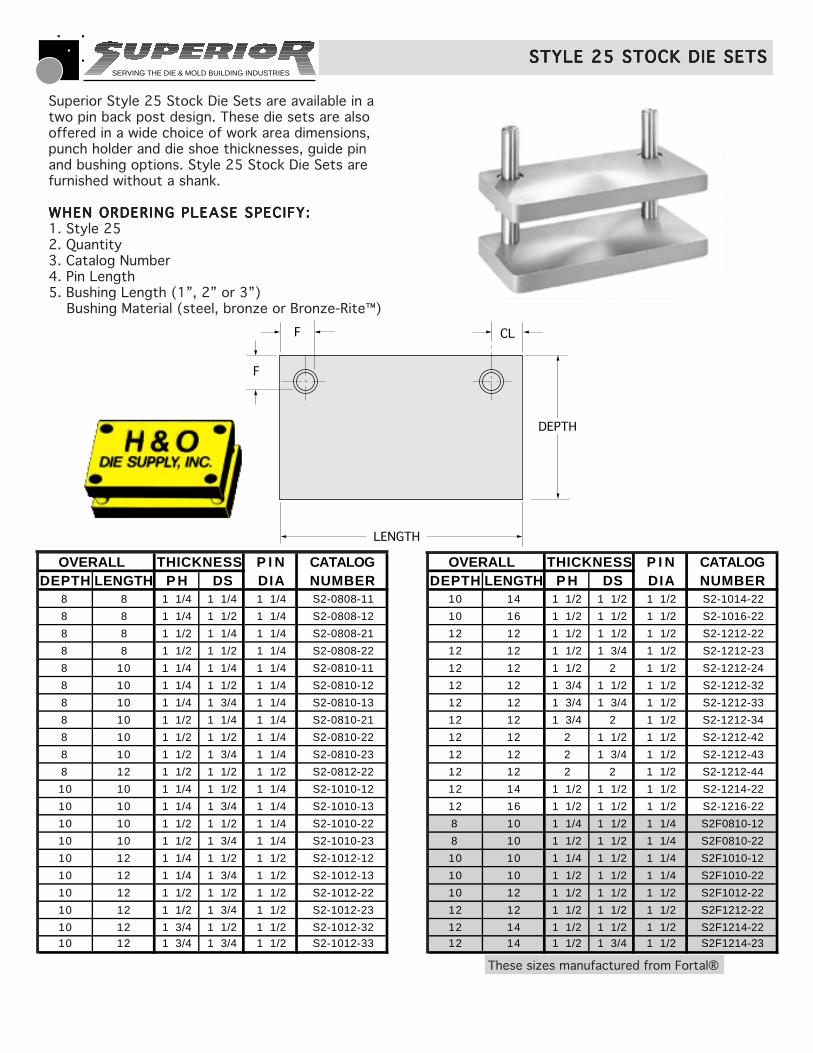
OVERALL THICKNESS P I N CATALOGDEPTH LENGTH P H DS DIA NUMBER
8 8 1 1/4 1 1/4 1 1/4 S2-0808-11
8 8 1 1/4 1 1/2 1 1/4 S2-0808-12
8 8 1 1/2 1 1/4 1 1/4 S2-0808-21
8 8 1 1/2 1 1/2 1 1/4 S2-0808-22
8 10 1 1/4 1 1/4 1 1/4 S2-0810-11
8 10 1 1/4 1 1/2 1 1/4 S2-0810-12
8 10 1 1/4 1 3/4 1 1/4 S2-0810-13
8 10 1 1/2 1 1/4 1 1/4 S2-0810-21
8 10 1 1/2 1 1/2 1 1/4 S2-0810-22
8 10 1 1/2 1 3/4 1 1/4 S2-0810-23
8 12 1 1/2 1 1/2 1 1/2 S2-0812-22
10 10 1 1/4 1 1/2 1 1/4 S2-1010-12
10 10 1 1/4 1 3/4 1 1/4 S2-1010-13
10 10 1 1/2 1 1/2 1 1/4 S2-1010-22
10 10 1 1/2 1 3/4 1 1/4 S2-1010-23
10 12 1 1/4 1 1/2 1 1/2 S2-1012-12
10 12 1 1/4 1 3/4 1 1/2 S2-1012-13
10 12 1 1/2 1 1/2 1 1/2 S2-1012-22
10 12 1 1/2 1 3/4 1 1/2 S2-1012-23
10 12 1 3/4 1 1/2 1 1/2 S2-1012-3210 12 1 3/4 1 3/4 1 1/2 S2-1012-33
OVERALL THICKNESS P I N CATALOGDEPTH LENGTH P H DS DIA NUMBER
10 14 1 1/2 1 1/2 1 1/2 S2-1014-22
10 16 1 1/2 1 1/2 1 1/2 S2-1016-22
12 12 1 1/2 1 1/2 1 1/2 S2-1212-22
12 12 1 1/2 1 3/4 1 1/2 S2-1212-23
12 12 1 1/2 2 1 1/2 S2-1212-24
12 12 1 3/4 1 1/2 1 1/2 S2-1212-32
12 12 1 3/4 1 3/4 1 1/2 S2-1212-33
12 12 1 3/4 2 1 1/2 S2-1212-34
12 12 2 1 1/2 1 1/2 S2-1212-42
12 12 2 1 3/4 1 1/2 S2-1212-43
12 12 2 2 1 1/2 S2-1212-44
12 14 1 1/2 1 1/2 1 1/2 S2-1214-22
12 16 1 1/2 1 1/2 1 1/2 S2-1216-22
8 10 1 1/4 1 1/2 1 1/4 S2F0810-12
8 10 1 1/2 1 1/2 1 1/4 S2F0810-22
10 10 1 1/4 1 1/2 1 1/4 S2F1010-12
10 10 1 1/2 1 1/2 1 1/4 S2F1010-22
10 12 1 1/2 1 1/2 1 1/2 S2F1012-22
12 12 1 1/2 1 1/2 1 1/2 S2F1212-22
12 14 1 1/2 1 1/2 1 1/2 S2F1214-2212 14 1 1/2 1 3/4 1 1/2 S2F1214-23
F
F CL
DEPTH
LENGTH
These sizes manufactured from Fortal®
Superior Style 25 Stock Die Sets are available in atwo pin back post design. These die sets are alsooffered in a wide choice of work area dimensions,punch holder and die shoe thicknesses, guide pinand bushing options. Style 25 Stock Die Sets arefurnished without a shank.
WHEN ORDERING PLEASE SPECIFY:WHEN ORDERING PLEASE SPECIFY:WHEN ORDERING PLEASE SPECIFY:WHEN ORDERING PLEASE SPECIFY:WHEN ORDERING PLEASE SPECIFY:1. Style 252. Quantity3. Catalog Number4. Pin Length5. Bushing Length (1”, 2” or 3”) Bushing Material (steel, bronze or Bronze-Rite™)
STYLE 25 STOCK DIE SETSSTYLE 25 STOCK DIE SETSSTYLE 25 STOCK DIE SETSSTYLE 25 STOCK DIE SETSSTYLE 25 STOCK DIE SETS
SERVING THE DIE & MOLD BUILDING INDUSTRIES
STANDARD PIN LOCATIONS - FRICTION BEARINGGuide PinDiameter 1 1 1/4 1 1/2 1 3/4 2 2 1/2 3
FDimension 2 2 1/4 2 1/2 2 3/4 3 3 3/4 4 1/4
CLDimension 1 1/2 1 5/8 1 3/4 1 7/8 2 2 1/2 2 3/4
NOTE: F Dimension refers to distance from edge of die set to inside edge of pin. (Except on ball bearing die sets.) CL Dimension for the smaller pin is the same as the large pin.
NOTES: 1. For Ball Bearing Die Set Information.
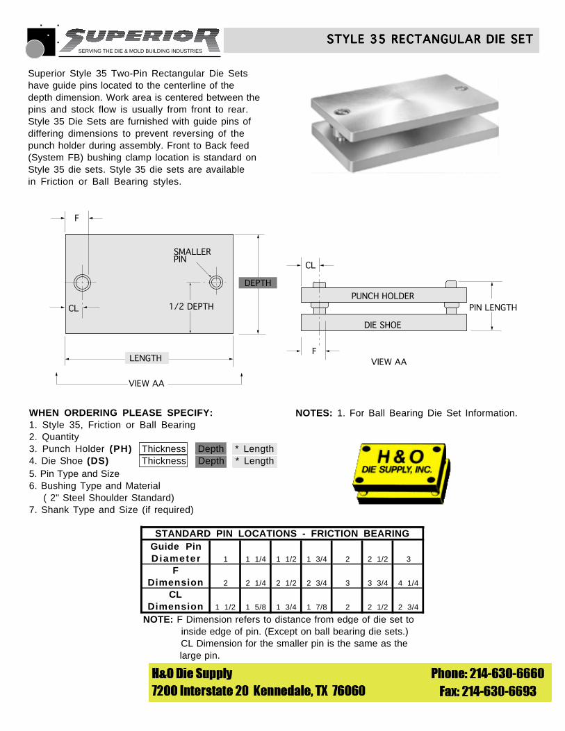
Superior Style 35 Two-Pin Rectangular Die Setshave guide pins located to the centerline of thedepth dimension. Work area is centered between thepins and stock flow is usually from front to rear.Style 35 Die Sets are furnished with guide pins of differing dimensions to prevent reversing of thepunch holder during assembly. Front to Back feed(System FB) bushing clamp location is standard onStyle 35 die sets. Style 35 die sets are availablein Friction or Ball Bearing styles.
© 1990 Superior Die Set Corp.
STYLE 35 RECTANGULAR DIE SETSTYLE 35 RECTANGULAR DIE SETSTYLE 35 RECTANGULAR DIE SETSTYLE 35 RECTANGULAR DIE SETSTYLE 35 RECTANGULAR DIE SET
F
CL
DEPTH
VIEW AA
VIEW AALENGTH
PUNCH HOLDER
DIE SHOE
F
PIN LENGTH
SMALLERPIN
CL
1/2 DEPTH
WHEN ORDERING PLEASE SPECIFY:1. Style 35, Friction or Ball Bearing2. Quantity3. Punch Holder (PH) Thickness Depth * Length4. Die Shoe (DS) Thickness Depth * Length5. Pin Type and Size6. Bushing Type and Material ( 2" Steel Shoulder Standard)7. Shank Type and Size (if required)
SERVING THE DIE & MOLD BUILDING INDUSTRIES
STANDARD PIN LOCATIONS - FRICTION BEARINGGuide PinDiameter 1 1 1/4 1 1/2 1 3/4 2 2 1/2 3
FDimension 2 2 1/4 2 1/2 2 3/4 3 3 3/4 4 1/4
CLDimension 1 1/2 1 5/8 1 3/4 1 7/8 2 2 1/2 2 3/4
NOTE: F Dimension refers to distance from edge of die set to inside edge of pin. (Except on ball bearing die sets.) CL Dimension for the smaller pin is the same as the large pin.
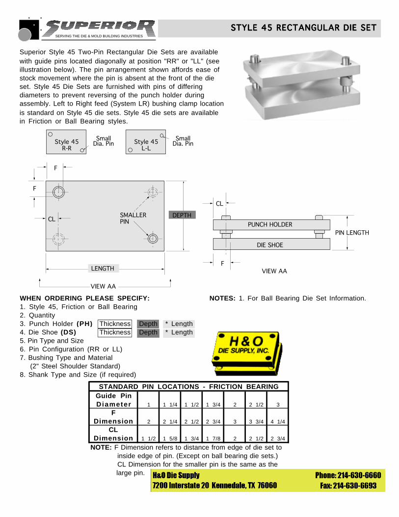
Superior Style 45 Two-Pin Rectangular Die Sets are availablewith guide pins located diagonally at position "RR" or "LL" (seeillustration below). The pin arrangement shown affords ease ofstock movement where the pin is absent at the front of the dieset. Style 45 Die Sets are furnished with pins of differingdiameters to prevent reversing of the punch holder duringassembly. Left to Right feed (System LR) bushing clamp locationis standard on Style 45 die sets. Style 45 die sets are availablein Friction or Ball Bearing styles.
© 1990 Superior Die Set Corp.
STYLE 45 RECTANGULAR DIE SETSTYLE 45 RECTANGULAR DIE SETSTYLE 45 RECTANGULAR DIE SETSTYLE 45 RECTANGULAR DIE SETSTYLE 45 RECTANGULAR DIE SET
F
F
CL
VIEW AA
VIEW AALENGTH
PUNCH HOLDER
DIE SHOE
F
PIN LENGTH
SMALLERPIN
CL
Style 45R-R
SmallDia. Pin Style 45
L-L
SmallDia. Pin
DEPTH
WHEN ORDERING PLEASE SPECIFY:1. Style 45, Friction or Ball Bearing2. Quantity3. Punch Holder (PH) Thickness Depth * Length4. Die Shoe (DS) Thickness Depth * Length5. Pin Type and Size6. Pin Configuration (RR or LL)7. Bushing Type and Material (2" Steel Shoulder Standard)8. Shank Type and Size (if required)
NOTES: 1. For Ball Bearing Die Set Information.
SERVING THE DIE & MOLD BUILDING INDUSTRIES
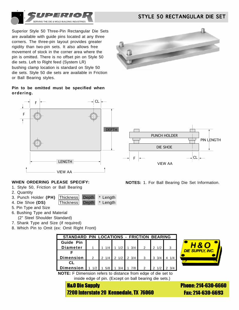
Superior Style 50 Three-Pin Rectangular Die Setsare available with guide pins located at any threecorners. The three-pin layout provides greaterrigidity than two-pin sets. It also allows freemovement of stock in the corner area where thepin is omitted. There is no offset pin on Style 50 die sets. Left to Right feed (System LR) bushing clamp location is standard on Style 50 die sets. Style 50 die sets are available in Friction or Ball Bearing styles.
Pin to be omitted must be specified whenordering.
STANDARD PIN LOCATIONS - FRICTION BEARINGGuide PinDiameter 1 1 1/4 1 1/2 1 3/4 2 2 1/2 3
FDimension 2 2 1/4 2 1/2 2 3/4 3 3 3/4 4 1/4
CLDimension 1 1/2 1 5/8 1 3/4 1 7/8 2 2 1/2 2 3/4
NOTE: F Dimension refers to distance from edge of die set to inside edge of pin. (Except on ball bearing die sets.)
© 1990 Superior Die Set Corp.
STYLE 50 RECTANGULAR DIE SETSTYLE 50 RECTANGULAR DIE SETSTYLE 50 RECTANGULAR DIE SETSTYLE 50 RECTANGULAR DIE SETSTYLE 50 RECTANGULAR DIE SET
F
F CL
CL
DEPTH
VIEW AA
VIEW AALENGTH
PUNCH HOLDER
DIE SHOE
F
PIN LENGTH
WHEN ORDERING PLEASE SPECIFY:1. Style 50, Friction or Ball Bearing2. Quantity3. Punch Holder (PH) Thickness Depth * Length4. Die Shoe (DS) Thickness Depth * Length5. Pin Type and Size6. Bushing Type and Material (2" Steel Shoulder Standard)7. Shank Type and Size (if required)8. Which Pin to Omit (ex: Omit Right Front)
NOTES: 1. For Ball Bearing Die Set Information.
SERVING THE DIE & MOLD BUILDING INDUSTRIES
STANDARD PIN LOCATIONS - FRICTION BEARINGGuide PinDiameter 1 1 1/4 1 1/2 1 3/4 2 2 1/2 3
FDimension 2 2 1/4 2 1/2 2 3/4 3 3 3/4 4 1/4
CLDimension 1 1/2 1 5/8 1 3/4 1 7/8 2 2 1/2 2 3/4
NOTE: F Dimension refers to distance from edge of die set to inside edge of pin. (Except on ball bearing die sets.)
Superior Style 75 Four-Pin Rectangular Die Sets aredesigned for applications where multi-directional orunequal tooling forces are generated by a non-symmetrical die shape or heavy stock. The four-pinarrangement provides maximum resistance to side thrustand misalignment. On Style 75 Die Sets, the right rearpin is offset 1/8" to left direction to prevent reversing ofthe punch holder during assembly. Inverted die sets,right front pin is offset by 1/8". Left to Right feed(System LR) bushing clamp location is standard on Style75 die sets. Style 75 die sets are available in Friction or Ball Bearing styles.
© 1990 Superior Die Set Corp.
STYLE 75 RECTANGULAR DIE SETSTYLE 75 RECTANGULAR DIE SETSTYLE 75 RECTANGULAR DIE SETSTYLE 75 RECTANGULAR DIE SETSTYLE 75 RECTANGULAR DIE SET
F
F
CL
CL
DEPTH
VIEW AA
VIEW AALENGTH
PUNCH HOLDER
DIE SHOE
F
PIN LENGTH
OFFSETPIN1/8”
WHEN ORDERING PLEASE SPECIFY:1. Style 75, Friction or Ball Bearing2. Quantity3. Punch Holder (PH) Thickness Depth * Length4. Die Shoe (DS) Thickness Depth * Length5. Pin Type and Size6. Bushing Type and Material (2" Steel Shoulder Standard)7. Shank Type and Size (if required)
NOTES: 1. For Ball Bearing Die Set Information.
SERVING THE DIE & MOLD BUILDING INDUSTRIES
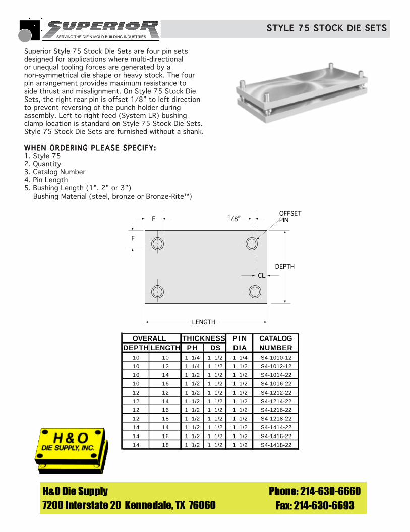
OVERALL THICKNESS P I N CATALOGDEPTH LENGTH P H DS DIA NUMBER
10 10 1 1/4 1 1/2 1 1/4 S4-1010-12
10 12 1 1/4 1 1/2 1 1/2 S4-1012-12
10 14 1 1/2 1 1/2 1 1/2 S4-1014-22
10 16 1 1/2 1 1/2 1 1/2 S4-1016-22
12 12 1 1/2 1 1/2 1 1/2 S4-1212-22
12 14 1 1/2 1 1/2 1 1/2 S4-1214-22
12 16 1 1/2 1 1/2 1 1/2 S4-1216-22
12 18 1 1/2 1 1/2 1 1/2 S4-1218-22
14 14 1 1/2 1 1/2 1 1/2 S4-1414-22
14 16 1 1/2 1 1/2 1 1/2 S4-1416-22
14 18 1 1/2 1 1/2 1 1/2 S4-1418-22
F
F
CL
DEPTH
LENGTH
OFFSETPIN1/8”
Superior Style 75 Stock Die Sets are four pin setsdesigned for applications where multi-directionalor unequal tooling forces are generated by anon-symmetrical die shape or heavy stock. The fourpin arrangement provides maximum resistance toside thrust and misalignment. On Style 75 Stock DieSets, the right rear pin is offset 1/8” to left directionto prevent reversing of the punch holder duringassembly. Left to right feed (System LR) bushingclamp location is standard on Style 75 Stock Die Sets.Style 75 Stock Die Sets are furnished without a shank.
WHEN ORDERING PLEASE SPECIFY:WHEN ORDERING PLEASE SPECIFY:WHEN ORDERING PLEASE SPECIFY:WHEN ORDERING PLEASE SPECIFY:WHEN ORDERING PLEASE SPECIFY:1. Style 752. Quantity3. Catalog Number4. Pin Length5. Bushing Length (1”, 2” or 3”) Bushing Material (steel, bronze or Bronze-Rite™)
STYLE 75 STOCK DIE SETSSTYLE 75 STOCK DIE SETSSTYLE 75 STOCK DIE SETSSTYLE 75 STOCK DIE SETSSTYLE 75 STOCK DIE SETS
SERVING THE DIE & MOLD BUILDING INDUSTRIES
© 1991 Superior Die Set Corp.
MULTI-SLIDE DIE SETSMULTI-SLIDE DIE SETSMULTI-SLIDE DIE SETSMULTI-SLIDE DIE SETSMULTI-SLIDE DIE SETS
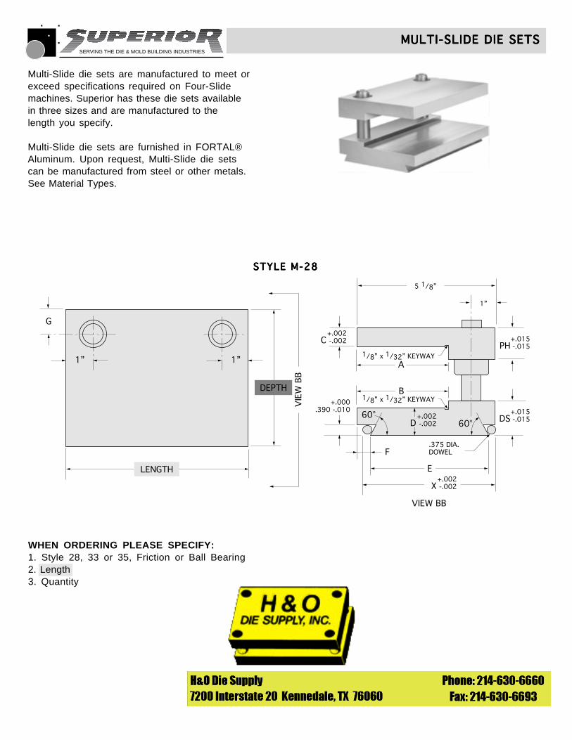
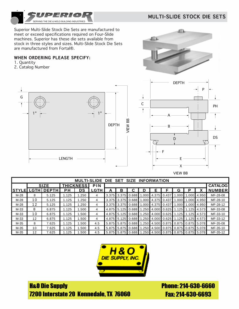
WHEN ORDERING PLEASE SPECIFY:1. Style 28, 33 or 35, Friction or Ball Bearing2. Length3. Quantity
G
1” 1”
DEPTH
LENGTH
VIE
W B
B
VIEW BB
+.002C -.002
+.000.390 -.010
+.015PH -.015
+.015DS -.015
A
B
E
1”
F
5 1/8”
1/8” x 1/32” KEYWAY
1/8” x 1/32” KEYWAY
60°60°
+.002D -.002
+.002X -.002
.375 DIA.DOWEL
STYLE M-28STYLE M-28STYLE M-28STYLE M-28STYLE M-28
Multi-Slide die sets are manufactured to meet orexceed specifications required on Four-Slidemachines. Superior has these die sets availablein three sizes and are manufactured to thelength you specify.
Multi-Slide die sets are furnished in FORTAL®Aluminum. Upon request, Multi-Slide die setscan be manufactured from steel or other metals.See Material Types.
SERVING THE DIE & MOLD BUILDING INDUSTRIES
MULTI-SLIDE DIE SETSMULTI-SLIDE DIE SETSMULTI-SLIDE DIE SETSMULTI-SLIDE DIE SETSMULTI-SLIDE DIE SETS
STYLE M-33STYLE M-33STYLE M-33STYLE M-33STYLE M-33
© 1991 Superior Die Set Corp.
G
1” 1”
DEPTH
LENGTH
VIE
W B
BVIEW BB
6 7/8”
1 1 /8
1/8 x 1/32 KEYWAY
1/8 x 3/32 KEYWAY
PH+.015-.015C
+.002-.002
.390+.000-.010
A
B
.375 DIA.DOWELF
DS +.015-.015
D+.002-.002
E
X+.002-.002
60° 60°
STYLE M-35STYLE M-35STYLE M-35STYLE M-35STYLE M-35
G
1” 1”
DEPTH
LENGTH
VIE
W B
B
VIEW BB
7 5/8”
7/8”
1/8 x 1/32 KEYWAY
1/8 x 1/32 KEYWAY
PH+.015-.015C
+.002-.002
.390+.000-.010
A
B
.375 DIA.DOWELF
DS+.015-.015
E
X+.002-.002
60° 60°D
+.002-.002
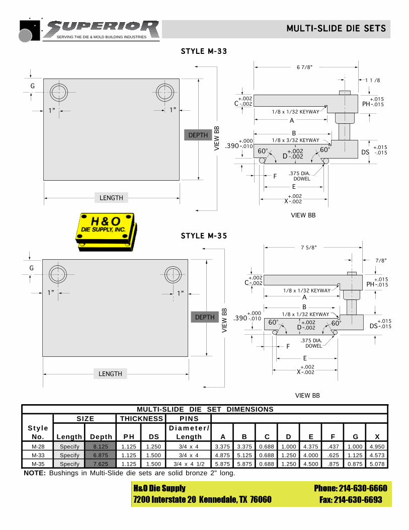
MULTI-SLIDE DIE SET DIMENSIONSSIZE THICKNESS PINS
Sty le D i a m e t e r /No. Length Depth P H DS Length A B C D E F G XM-28 Specify 8.125 1.125 1.250 3/4 x 4 3.375 3.375 0.688 1.000 4.375 .437 1.000 4.950
M-33 Specify 6.875 1.125 1.500 3/4 x 4 4.875 5.125 0.688 1.250 4.000 .625 1.125 4.573
M-35 Specify 7.625 1.125 1.500 3/4 x 4 1/2 5.875 5.875 0.688 1.250 4.500 .875 0.875 5.078
NOTE: Bushings in Multi-Slide die sets are solid bronze 2" long.
SERVING THE DIE & MOLD BUILDING INDUSTRIES
G
1” 1”
DEPTH
LENGTH
VIE
W B
B
VIEW BB
C
A
B
DS
E
PH
P
D
X
F
DEPTH
MULTI-SLIDE DIE SET SIZE INFORMATIONSIZE THICKNESS P I N CATALOG
STYLE LGTH DEPTH P H DS LGTH A B C D E F G P X NUMBERM-28 8 5.125 1.125 1.250 4 3.375 3.375 0.688 1.000 4.375 0.437 1.000 1.000 4.950 MF-28-08M-28 1 0 5.125 1.125 1.250 4 3.375 3.375 0.688 1.000 4.375 0.437 1.000 1.000 4.950 MF-28-10M-28 1 2 5.125 1.125 1.250 4 3.375 3.375 0.688 1.000 4.375 0.437 1.000 1.000 4.950 MF-28-12M-33 8 6.875 1.125 1.500 4 4.875 5.125 0.688 1.250 4.000 0.625 1.125 1.125 4.573 MF-33-08M-33 1 0 6.875 1.125 1.500 4 4.875 5.125 0.688 1.250 4.000 0.625 1.125 1.125 4.573 MF-33-10M-33 12 6.875 1.125 1.500 4 4.875 5.125 0.688 1.250 4.000 0.625 1.125 1.125 4.573 MF-33-12M-35 8 7.625 1.125 1.500 4.5 5.875 5.875 0.688 1.250 4.500 0.875 0.875 0.875 5.078 MF-35-08M-35 10 7.625 1.125 1.500 4.5 5.875 5.875 0.688 1.250 4.500 0.875 0.875 0.875 5.078 MF-35-10M-35 12 7.625 1.125 1.500 4.5 5.875 5.875 0.688 1.250 4.500 0.875 0.875 0.875 5.078 MF-35-12
Superior Multi-Slide Stock Die Sets are manufactured tomeet or exceed specifications required on Four-Slidemachines. Superior has these die sets available fromstock in three styles and sizes. Multi-Slide Stock Die Setsare manufactured from Fortal®.
WHEN ORDERING PLEASE SPECIFY:WHEN ORDERING PLEASE SPECIFY:WHEN ORDERING PLEASE SPECIFY:WHEN ORDERING PLEASE SPECIFY:WHEN ORDERING PLEASE SPECIFY:1. Quantity2. Catalog Number
MULTI-SLIDE STOCK DIE SETSMULTI-SLIDE STOCK DIE SETSMULTI-SLIDE STOCK DIE SETSMULTI-SLIDE STOCK DIE SETSMULTI-SLIDE STOCK DIE SETS
SERVING THE DIE & MOLD BUILDING INDUSTRIES
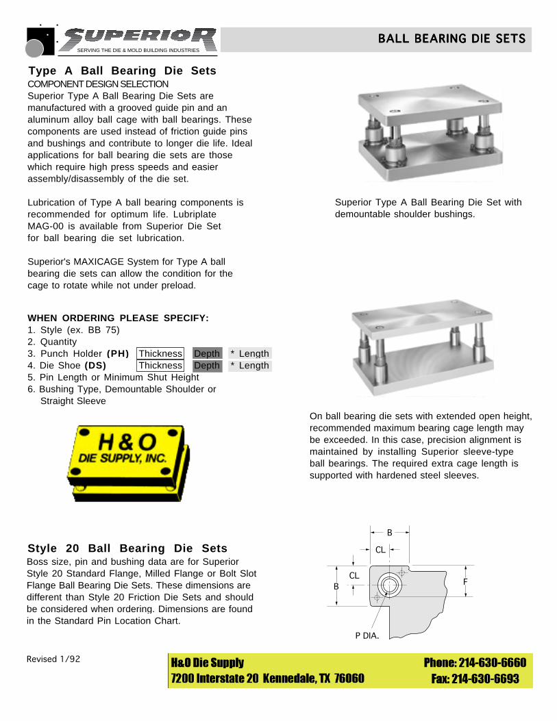
Style 20 Ball Bearing Die SetsBoss size, pin and bushing data are for SuperiorStyle 20 Standard Flange, Milled Flange or Bolt SlotFlange Ball Bearing Die Sets. These dimensions are different than Style 20 Friction Die Sets and should be considered when ordering. Dimensions are foundin the Standard Pin Location Chart.
Type A Ball Bearing Die SetsCOMPONENT DESIGN SELECTIONSuperior Type A Ball Bearing Die Sets aremanufactured with a grooved guide pin and analuminum alloy ball cage with ball bearings. Thesecomponents are used instead of friction guide pinsand bushings and contribute to longer die life. Idealapplications for ball bearing die sets are thosewhich require high press speeds and easierassembly/disassembly of the die set.
Lubrication of Type A ball bearing components isrecommended for optimum life. LubriplateMAG-00 is available from Superior Die Setfor ball bearing die set lubrication.
Superior's MAXICAGE System for Type A ballbearing die sets can allow the condition for thecage to rotate while not under preload.
Revised 1/92 © 1990 Superior Die Set Corp.
BALL BEARING DIE SETSBALL BEARING DIE SETSBALL BEARING DIE SETSBALL BEARING DIE SETSBALL BEARING DIE SETS
Superior Type A Ball Bearing Die Set withdemountable shoulder bushings.
CL
CL
P DIA.
B
B
F
On ball bearing die sets with extended open height,recommended maximum bearing cage length maybe exceeded. In this case, precision alignment ismaintained by installing Superior sleeve-type ball bearings. The required extra cage length issupported with hardened steel sleeves.
WHEN ORDERING PLEASE SPECIFY:1. Style (ex. BB 75)2. Quantity3. Punch Holder (PH) Thickness Depth * Length4. Die Shoe (DS) Thickness Depth * Length5. Pin Length or Minimum Shut Height6. Bushing Type, Demountable Shoulder or Straight Sleeve
SERVING THE DIE & MOLD BUILDING INDUSTRIES
Revised 1/92 © 1990 Superior Die Set Corp.
BALL BEARING DIE SETSBALL BEARING DIE SETSBALL BEARING DIE SETSBALL BEARING DIE SETSBALL BEARING DIE SETS
PUNCHHOLDER
SHOULDERBUSHING
DIESHOE
SLEEVEBUSHING
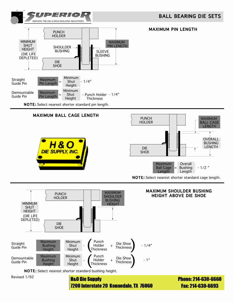
StraightGuide Pin
Demountable Guide Pin
- 1/4”
- Punch HolderThickness
- 1/4”
Maximum Pin Length
Maximum Pin Length
MinimumShut
Height
MinimumShut
Height
MAXIMUM PIN LENGTH
MINIMUMSHUT
HEIGHT
=
=
(DIE LIFEDEPLETED)
MAXIMUM PIN LENGTHMAXIMUM PIN LENGTHMAXIMUM PIN LENGTHMAXIMUM PIN LENGTHMAXIMUM PIN LENGTH
MAXIMUM BALL CAGE LENGTHMAXIMUM BALL CAGE LENGTHMAXIMUM BALL CAGE LENGTHMAXIMUM BALL CAGE LENGTHMAXIMUM BALL CAGE LENGTH
MAXIMUM SHOULDER BUSHINGMAXIMUM SHOULDER BUSHINGMAXIMUM SHOULDER BUSHINGMAXIMUM SHOULDER BUSHINGMAXIMUM SHOULDER BUSHINGHEIGHT ABOVE DIE SHOEHEIGHT ABOVE DIE SHOEHEIGHT ABOVE DIE SHOEHEIGHT ABOVE DIE SHOEHEIGHT ABOVE DIE SHOE
PUNCHHOLDER
DIESHOE
- 1/2 ” MaximumBall CageLength
OverallBushing Length
MAXIMUM BALL CAGE
LENGTH
OVERALLBUSHINGLENGTH
=
-
-
PUNCHHOLDER
DIESHOE
StraightGuide Pin
Demountable Guide Pin
- 1/4”Maximum BushingHeight
MaximumBushingHeight
MinimumShut
Height
MinimumShut
Height
MAXIMUMSHOULDERBUSHING HEIGHTMINIMUM
SHUTHEIGHT(DIE LIFE
DEPLETED)
PunchHolder
Thickness
Die ShoeThickness+
- 1”PunchHolder
Thickness
Die ShoeThickness+
( )
NOTE:NOTE :NOTE :NOTE :NOTE : Select nearest shorter standard bushing height.
NOTE :NOTE :NOTE :NOTE :NOTE : Select nearest shorter standard cage length.
NOTE :NOTE :NOTE :NOTE :NOTE : Select nearest shorter standard pin length.
( )
SERVING THE DIE & MOLD BUILDING INDUSTRIES
Revised 1/92 © 1990 Superior Die Set Corp.
BALL BEARING DIE SETSBALL BEARING DIE SETSBALL BEARING DIE SETSBALL BEARING DIE SETSBALL BEARING DIE SETS
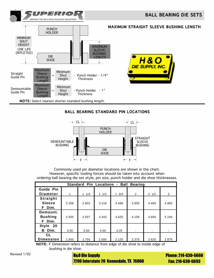
MAXIMUM STRAIGHT SLEEVE BUSHING LENGTHMAXIMUM STRAIGHT SLEEVE BUSHING LENGTHMAXIMUM STRAIGHT SLEEVE BUSHING LENGTHMAXIMUM STRAIGHT SLEEVE BUSHING LENGTHMAXIMUM STRAIGHT SLEEVE BUSHING LENGTH
NOTE:NOTE :NOTE :NOTE :NOTE : Select nearest shorter standard bushing length.
PUNCHHOLDER
DIESHOE
StraightGuide Pin
Demountable Guide Pin
- 1/4”
- Punch HolderThickness
- 1”
MaximumSleeveBushing Length
MaximumSleeveBushing Length
MinimumShut
Height
MinimumShut
Height
MAXIMUMSLEEVEBUSHING LENGTH
MINIMUMSHUT
HEIGHT
- Punch HolderThickness
(DIE LIFEDEPLETED)
=
=
BALL BEARING STANDARD PIN LOCATIONSBALL BEARING STANDARD PIN LOCATIONSBALL BEARING STANDARD PIN LOCATIONSBALL BEARING STANDARD PIN LOCATIONSBALL BEARING STANDARD PIN LOCATIONS
PUNCHHOLDER
DIESHOE
DEMOUNTABLEBUSHING
STRAIGHTSLEEVEBUSHING
CL CL
F F
Commonly used pin diameter locations are shown in the chart.However, specific tooling forces should be taken into account when
ordering ball bearing die set style, pin size, punch holder and die shoe thicknesses.
Standard Pin Locations - Ball BearingGuide PinDiameter 1 1 1/4 1 1/2 1 3/4 2 2 1/2 3
Stra ightSleeve 2.358 2.803 3.218 3.498 3.955 4.465 4.965
F Dim.Demount.Bushing 2.500 2.937 3.343 3.625 4.156 4.656 5.156
F Dim.Style 20
B Dim. 3.00 3.50 4.00 4.25 - - -
CLDimension 1.500 1.750 2.000 2.125 2.375 2.625 2.875
NOTE: F Dimension refers to distance from edge of die shoe to inside edge of bushing in die shoe.
SERVING THE DIE & MOLD BUILDING INDUSTRIES
Revised 1/92 © 1990 Superior Die Set Corp.
BALL BEARING DIE SETSBALL BEARING DIE SETSBALL BEARING DIE SETSBALL BEARING DIE SETSBALL BEARING DIE SETS
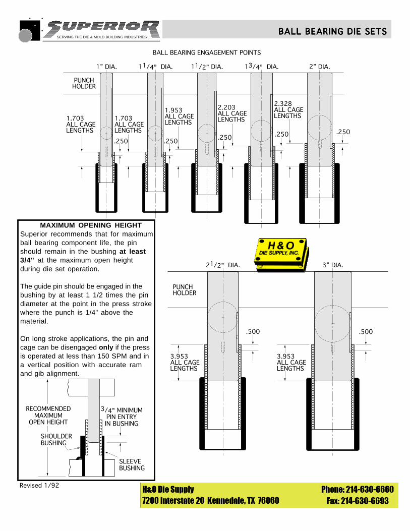
BALL BEARING ENGAGEMENT POINTS
1” DIA. 11/4” DIA. 11/2” DIA. 13/4” DIA. 2” DIA.
PUNCHHOLDER
1.703ALL CAGELENGTHS
1.703ALL CAGELENGTHS
1.953ALL CAGELENGTHS
2.203ALL CAGELENGTHS
2.328ALL CAGELENGTHS
.250.250.250.250.250
21/2” DIA. 3” DIA.
3.953ALL CAGELENGTHS
PUNCHHOLDER
3.953ALL CAGELENGTHS
.500 .500
3/4” MINIMUMPIN ENTRYIN BUSHING
SLEEVE BUSHING
SHOULDERBUSHING
RECOMMENDEDMAXIMUM
OPEN HEIGHT
MAXIMUM OPENING HEIGHTSuperior recommends that for maximumball bearing component life, the pinshould remain in the bushing at least3/4" at the maximum open heightduring die set operation.
The guide pin should be engaged in thebushing by at least 1 1/2 times the pindiameter at the point in the press strokewhere the punch is 1/4" above thematerial.
On long stroke applications, the pin andcage can be disengaged only if the pressis operated at less than 150 SPM and ina vertical position with accurate ramand gib alignment.
SERVING THE DIE & MOLD BUILDING INDUSTRIES
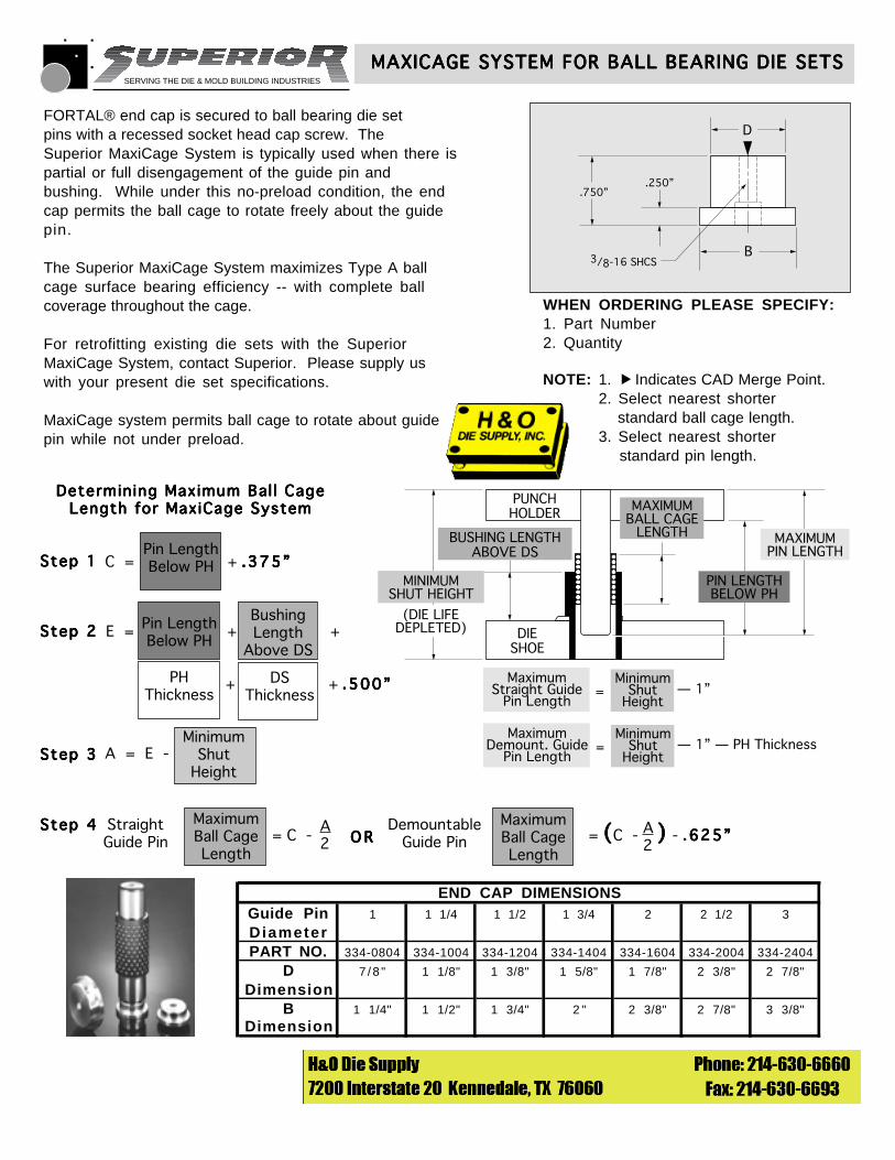
NOTE: 1. Indicates CAD Merge Point.2. Select nearest shorter standard ball cage length.3. Select nearest shorter standard pin length.
PUNCHHOLDER
DIESHOE
BUSHING LENGTHABOVE DS
MAXIMUMBALL CAGE
LENGTH MAXIMUMPIN LENGTH
PIN LENGTHBELOW PH
MINIMUMSHUT HEIGHT
(DIE LIFEDEPLETED)
MaximumStraight Guide
Pin Length
MinimumShut
Height= — 1”
MaximumDemount. Guide
Pin Length
MinimumShut
Height= — 1” — PH Thickness
WHEN ORDERING PLEASE SPECIFY:1. Part Number2. Quantity
MAXICAGE SYSTEM FOR BALL BEARING DIE SETSMAXICAGE SYSTEM FOR BALL BEARING DIE SETSMAXICAGE SYSTEM FOR BALL BEARING DIE SETSMAXICAGE SYSTEM FOR BALL BEARING DIE SETSMAXICAGE SYSTEM FOR BALL BEARING DIE SETS
© 1993 Superior Die Set Corp.
FORTAL® end cap is secured to ball bearing die setpins with a recessed socket head cap screw. TheSuperior MaxiCage System is typically used when there ispartial or full disengagement of the guide pin andbushing. While under this no-preload condition, the endcap permits the ball cage to rotate freely about the guidepin.
The Superior MaxiCage System maximizes Type A ballcage surface bearing efficiency -- with complete ballcoverage throughout the cage.
For retrofitting existing die sets with the SuperiorMaxiCage System, contact Superior. Please supply uswith your present die set specifications.
MaxiCage system permits ball cage to rotate about guidepin while not under preload.
▲
END CAP DIMENSIONSGuide Pin 1 1 1/4 1 1/2 1 3/4 2 2 1/2 3
DiameterPART NO. 334-0804 334-1004 334-1204 334-1404 334-1604 334-2004 334-2404
D 7 / 8 " 1 1/8" 1 3/8" 1 5/8" 1 7/8" 2 3/8" 2 7/8"
DimensionB 1 1/4" 1 1/2" 1 3/4" 2 " 2 3/8" 2 7/8" 3 3/8"
Dimension
Determining Maximum Bal l CageDetermining Maximum Bal l CageDetermining Maximum Bal l CageDetermining Maximum Bal l CageDetermining Maximum Bal l CageLength for MaxiCage SystemLength for MaxiCage SystemLength for MaxiCage SystemLength for MaxiCage SystemLength for MaxiCage System
Step 1Step 1Step 1Step 1Step 1
Step 2Step 2Step 2Step 2Step 2
Step 3Step 3Step 3Step 3Step 3
Step 4Step 4Step 4Step 4Step 4 MaximumBall CageLength
= C -A2
StraightGuide Pin
DemountableGuide Pin
MaximumBall CageLength
= C - - .625”.625”.625”.625”.625”( )( )( )( )( )A2
MinimumShut
HeightA = E -
Pin LengthBelow PHC = + .375”.375”.375”.375”.375”
BushingLength
Above DS
Pin LengthBelow PH
E = + +
+ + .500”.500”.500”.500”.500”DSThickness
PHThickness
.750”
B
D
.250”
3/8-16 SHCS
O RO RO RO RO R
SERVING THE DIE & MOLD BUILDING INDUSTRIES
Revised 1/92 © 1990 Superior Die Set Corp.
DIE SET HANDLING HOLESDIE SET HANDLING HOLESDIE SET HANDLING HOLESDIE SET HANDLING HOLESDIE SET HANDLING HOLES
DS 1/2 DS
1/2 PHPH J
DEPTH
LENGTH
OPTION 2
1/2 DS
DSPH
1/2 PH
DEPTH OPTION 3
LENGTH
J
DS1/2 DS
1/2 PHPH
1/2LENGTH
DEPTH
1/2 DEPTH
OPTION 1
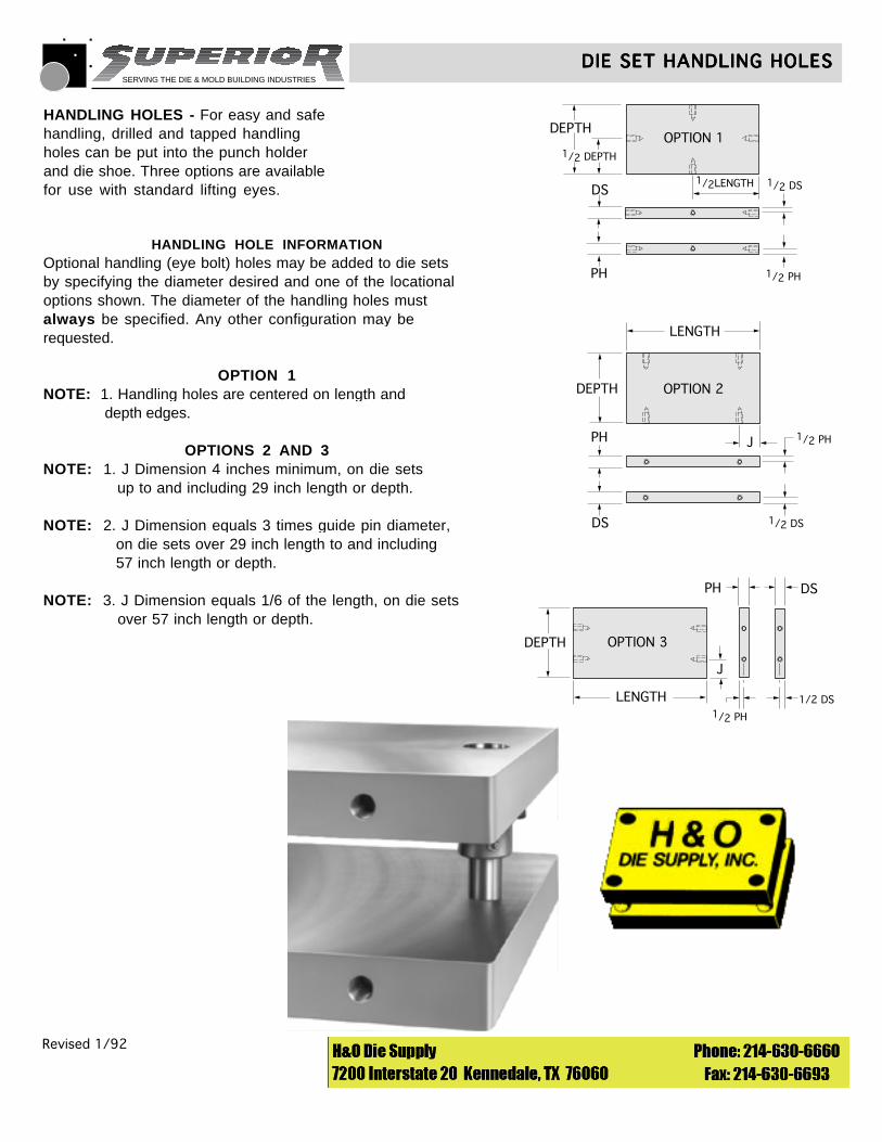
HANDLING HOLES - For easy and safehandling, drilled and tapped handlingholes can be put into the punch holderand die shoe. Three options are availablefor use with standard lifting eyes.
HANDLING HOLE INFORMATIONOptional handling (eye bolt) holes may be added to die setsby specifying the diameter desired and one of the locationaloptions shown. The diameter of the handling holes mustalways be specified. Any other configuration may berequested.
OPTION 1NOTE: 1. Handling holes are centered on length and depth edges.
OPTIONS 2 AND 3NOTE: 1. J Dimension 4 inches minimum, on die sets up to and including 29 inch length or depth.
NOTE: 2. J Dimension equals 3 times guide pin diameter, on die sets over 29 inch length to and including 57 inch length or depth.
NOTE: 3. J Dimension equals 1/6 of the length, on die sets over 57 inch length or depth.
SERVING THE DIE & MOLD BUILDING INDUSTRIES
Revised 1/92 © 1990 Superior Die Set Corp.
PRODUCT FEATURES AND SERVICESPRODUCT FEATURES AND SERVICESPRODUCT FEATURES AND SERVICESPRODUCT FEATURES AND SERVICESPRODUCT FEATURES AND SERVICES
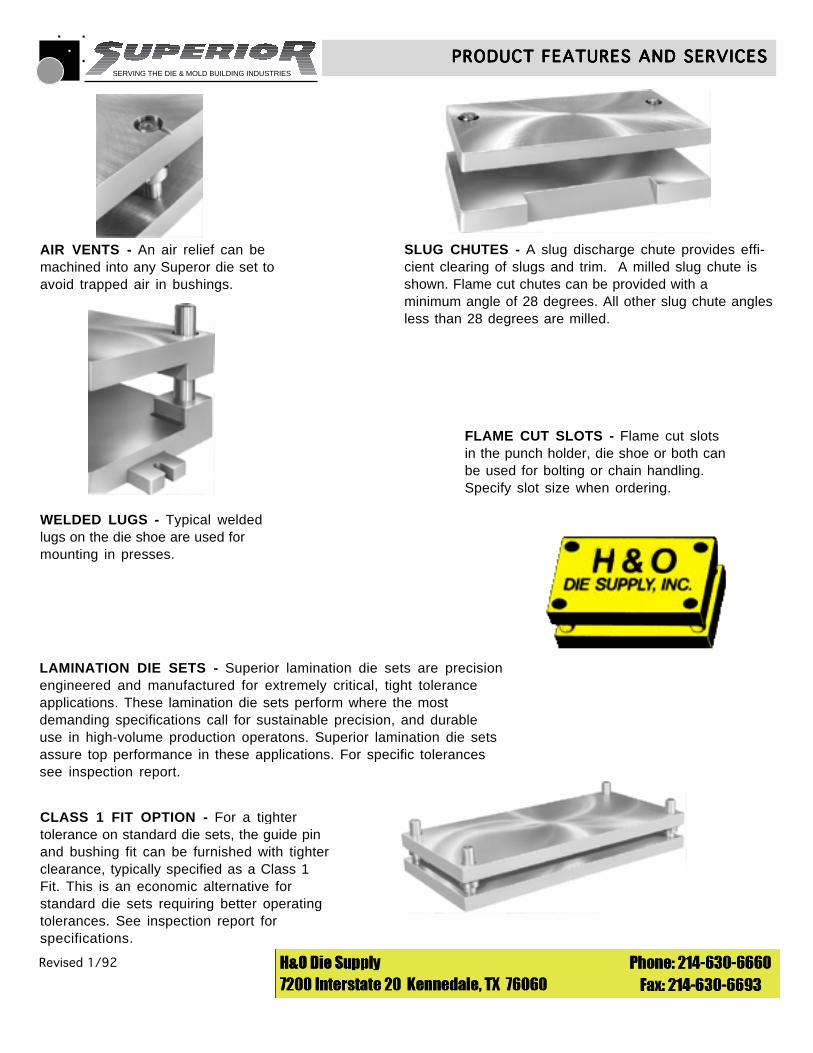
AIR VENTS - An air relief can bemachined into any Superor die set toavoid trapped air in bushings.
SLUG CHUTES - A slug discharge chute provides effi-cient clearing of slugs and trim. A milled slug chute isshown. Flame cut chutes can be provided with aminimum angle of 28 degrees. All other slug chute anglesless than 28 degrees are milled.
WELDED LUGS - Typical weldedlugs on the die shoe are used formounting in presses.
FLAME CUT SLOTS - Flame cut slotsin the punch holder, die shoe or both canbe used for bolting or chain handling.Specify slot size when ordering.
LAMINATION DIE SETS - Superior lamination die sets are precisionengineered and manufactured for extremely critical, tight toleranceapplications. These lamination die sets perform where the mostdemanding specifications call for sustainable precision, and durableuse in high-volume production operatons. Superior lamination die setsassure top performance in these applications. For specific tolerancessee inspection report.
CLASS 1 FIT OPTION - For a tightertolerance on standard die sets, the guide pinand bushing fit can be furnished with tighterclearance, typically specified as a Class 1Fit. This is an economic alternative forstandard die sets requiring better operatingtolerances. See inspection report forspecifications.
SERVING THE DIE & MOLD BUILDING INDUSTRIES
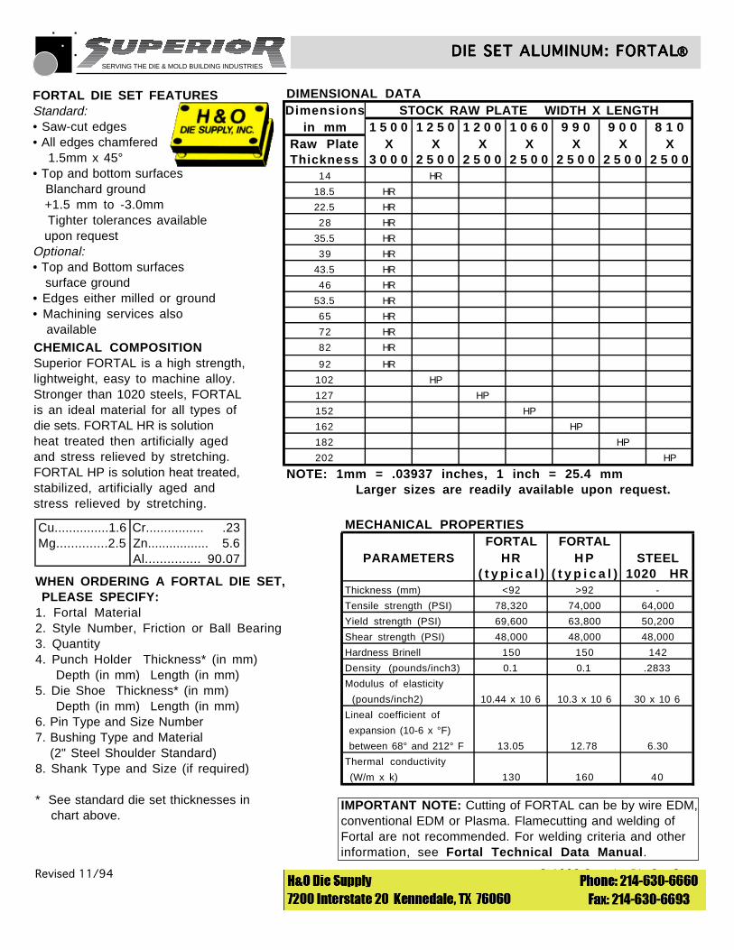
CHEMICAL COMPOSITIONSuperior FORTAL is a high strength,lightweight, easy to machine alloy.Stronger than 1020 steels, FORTALis an ideal material for all types ofdie sets. FORTAL HR is solutionheat treated then artificially agedand stress relieved by stretching.FORTAL HP is solution heat treated, stabilized, artificially aged andstress relieved by stretching.
IMPORTANT NOTE: Cutting of FORTAL can be by wire EDM,conventional EDM or Plasma. Flamecutting and welding ofFortal are not recommended. For welding criteria and other information, see Fortal Technical Data Manual.
WHEN ORDERING A FORTAL DIE SET, PLEASE SPECIFY:1. Fortal Material2. Style Number, Friction or Ball Bearing3. Quantity4. Punch Holder Thickness* (in mm) Depth (in mm) Length (in mm)5. Die Shoe Thickness* (in mm) Depth (in mm) Length (in mm)6. Pin Type and Size Number7. Bushing Type and Material (2" Steel Shoulder Standard)8. Shank Type and Size (if required)
* See standard die set thicknesses in chart above.
Revised 11/94 © 1993 Superior Die Set Corp.
DIE SET ALUMINUM: FORTALDIE SET ALUMINUM: FORTALDIE SET ALUMINUM: FORTALDIE SET ALUMINUM: FORTALDIE SET ALUMINUM: FORTAL®®®®®
Cu...............1.6 Cr................ .23Mg..............2.5 Zn................. 5.6
Al............... 90.07
FORTAL DIE SET FEATURESStandard:• Saw-cut edges• All edges chamfered 1.5mm x 45°• Top and bottom surfaces Blanchard ground +1.5 mm to -3.0mm Tighter tolerances available upon requestOptional:• Top and Bottom surfaces surface ground• Edges either milled or ground• Machining services also available
MECHANICAL PROPERTIESFORTAL FORTAL
PARAMETERS HR H P STEEL( t y p i c a l ) ( t y p i c a l ) 1020 HR
Thickness (mm) <92 >92 -
Tensile strength (PSI) 78,320 74,000 64,000
Yield strength (PSI) 69,600 63,800 50,200
Shear strength (PSI) 48,000 48,000 48,000
Hardness Brinell 150 150 142
Density (pounds/inch3) 0.1 0.1 .2833
Modulus of elasticity
(pounds/inch2) 10.44 x 10 6 10.3 x 10 6 30 x 10 6
Lineal coefficient of
expansion (10-6 x °F)
between 68° and 212° F 13.05 12.78 6.30
Thermal conductivity
(W/m x k) 130 160 40
DIMENSIONAL DATADimensions STOCK RAW PLATE WIDTH X LENGTH
in mm 1 5 0 0 1 2 5 0 1 2 0 0 1 0 6 0 9 9 0 9 0 0 8 1 0Raw Plate X X X X X X XThickness 3 0 0 0 2 5 0 0 2 5 0 0 2 5 0 0 2 5 0 0 2 5 0 0 2 5 0 0
14 HR
18.5 HR
22.5 HR
28 HR
35.5 HR
39 HR
43.5 HR
46 HR
53.5 HR
65 HR
72 HR
82 HR
92 HR
102 HP
127 HP
152 HP
162 HP
182 HP
202 HP
NOTE: 1mm = .03937 inches, 1 inch = 25.4 mm Larger sizes are readily available upon request.
SERVING THE DIE & MOLD BUILDING INDUSTRIES
Revised 1/92 © 1990 Superior Die Set Corp.
BOSS DIE SETSBOSS DIE SETSBOSS DIE SETSBOSS DIE SETSBOSS DIE SETS
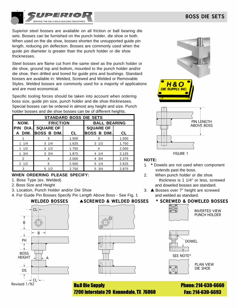
PIN LENGTHABOVE BOSS
FIGURE 1
STANDARD BOSS DIE SETSNOM. FRICTION BALL BEARING
PIN DIA. SQUARE OF SQUARE OFA DIM. BOSS B DIM. CL BOSS B DIM. CL
1 3 1.500 3 1.500
1 1/4 3 1/4 1.625 3 1/2 1.750
1 1/2 3 1/2 1.750 4 2.000
1 3/4 3 3/4 1.875 4 1/4 2.125
2 4 2.000 4 3/4 2.375
2 1/2 5 2.500 5 1/4 2.625
3 5 1/2 2.750 5 3/4 2.875
WHEN ORDERING PLEASE SPECIFY:1. Boss Type (ex. Welded)2. Boss Size and Height3. Location, Punch Holder and/or Die Shoe4. For Guide Pin Bosses Specify Pin Length Above Boss - See Fig. 1
Superior steel bosses are available on all friction or ball bearing diesets. Bosses can be furnished on the punch holder, die shoe or both.When used on the die shoe, bosses shorten the unsupported guide pinlength, reducing pin deflection. Bosses are commonly used when theguide pin diameter is greater than the punch holder or die shoethicknesses.
Steel bosses are flame cut from the same steel as the punch holder ordie shoe, ground top and bottom, mounted to the punch holder and/ordie shoe, then drilled and bored for guide pins and bushings. Standardbosses are available in: Welded, Screwed and Welded or RemovableStyles. Welded bosses are commonly used for a majority of applicationsand are most economical.
Specific tooling forces should be taken into account when orderingboss size, guide pin size, punch holder and die shoe thicknesses.Special bosses can be ordered in almost any height and size. Punchholder bosses and die shoe bosses can be of different heights.
WELDED BOSSESWELDED BOSSESWELDED BOSSESWELDED BOSSESWELDED BOSSES
CL
CL
PH
BOSSHEIGHT A
DS
B
B
SCREWED & WELDED BOSSESSCREWED & WELDED BOSSESSCREWED & WELDED BOSSESSCREWED & WELDED BOSSESSCREWED & WELDED BOSSES
INVERTED VIEWPUNCH HOLDER
PLAN VIEWDIE SHOE
DOWEL
SEE NOTE*
* SCREWED & DOWELED BOSSES* SCREWED & DOWELED BOSSES* SCREWED & DOWELED BOSSES* SCREWED & DOWELED BOSSES* SCREWED & DOWELED BOSSES▲
NOTE:1. * Dowels are not used when component extends past the boss.2. When punch holder or die shoe thickness is 1 1/4" or less, screwed and doweled bosses are standard.3. Bosses over 7" height are screwed and welded as standard.
▲
SERVING THE DIE & MOLD BUILDING INDUSTRIES
© 1990 Superior Die Set Corp.
WEAR PLATE DIE SETSWEAR PLATE DIE SETSWEAR PLATE DIE SETSWEAR PLATE DIE SETSWEAR PLATE DIE SETS
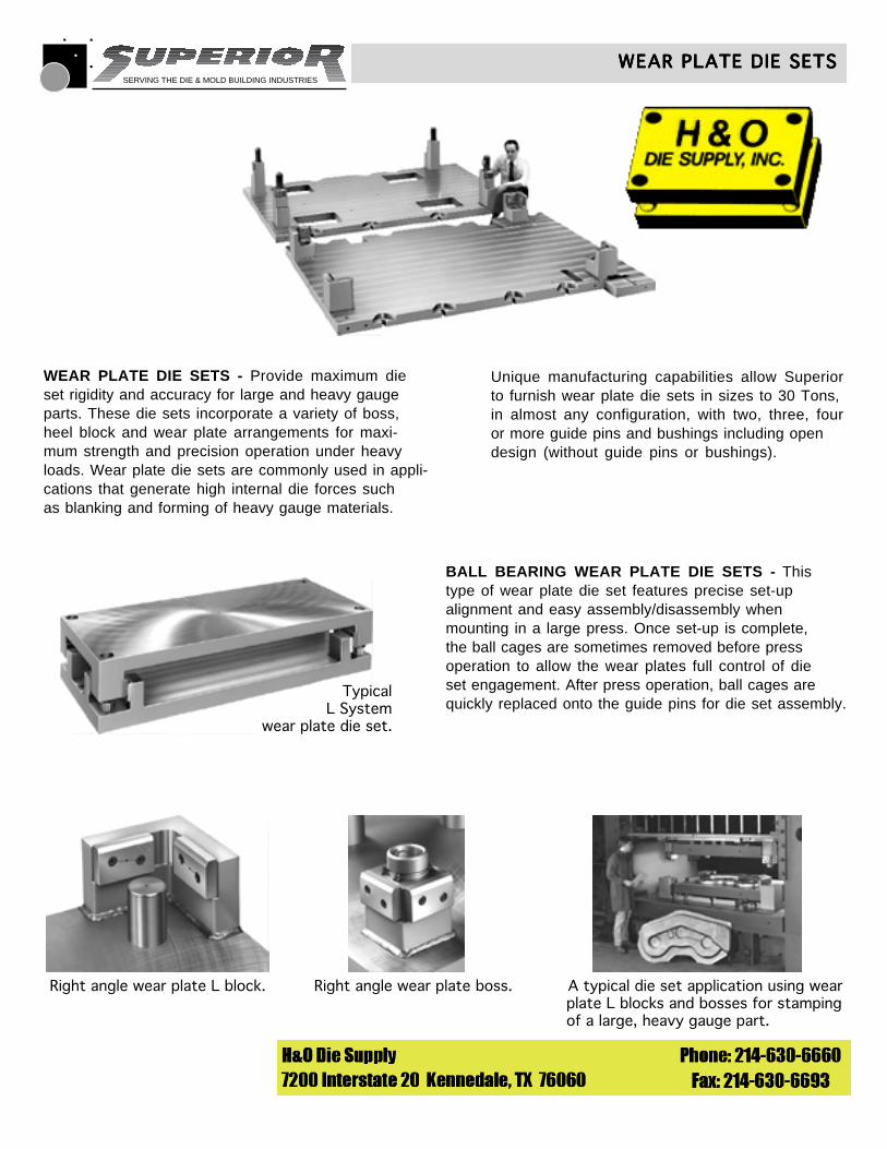
WEAR PLATE DIE SETS - Provide maximum dieset rigidity and accuracy for large and heavy gaugeparts. These die sets incorporate a variety of boss,heel block and wear plate arrangements for maxi-mum strength and precision operation under heavyloads. Wear plate die sets are commonly used in appli-cations that generate high internal die forces suchas blanking and forming of heavy gauge materials.
Unique manufacturing capabilities allow Superiorto furnish wear plate die sets in sizes to 30 Tons,in almost any configuration, with two, three, fouror more guide pins and bushings including opendesign (without guide pins or bushings).
BALL BEARING WEAR PLATE DIE SETS - Thistype of wear plate die set features precise set-upalignment and easy assembly/disassembly whenmounting in a large press. Once set-up is complete,the ball cages are sometimes removed before pressoperation to allow the wear plates full control of dieset engagement. After press operation, ball cages are quickly replaced onto the guide pins for die set assembly.
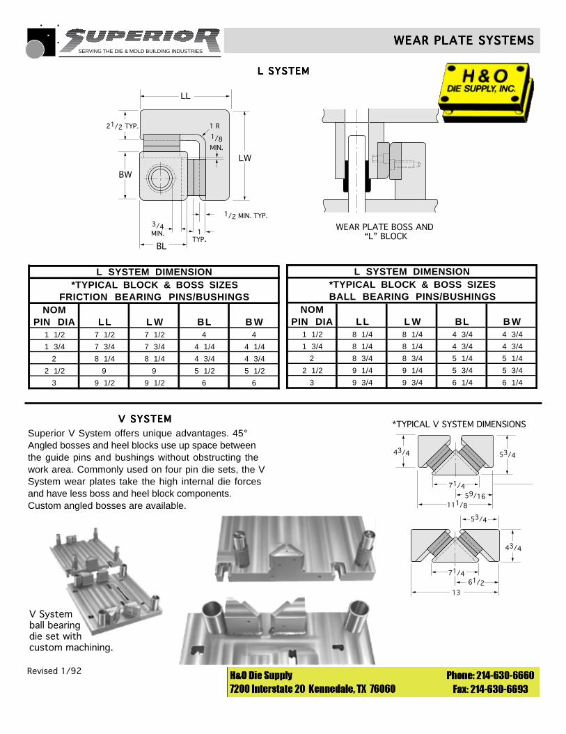
TypicalL System
wear plate die set.
Right angle wear plate L block. Right angle wear plate boss. A typical die set application using wearplate L blocks and bosses for stampingof a large, heavy gauge part.
SERVING THE DIE & MOLD BUILDING INDUSTRIES
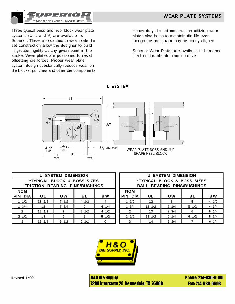
21/2TYP.
1TYP.
1TYP.
3/4MIN.
1/8MIN.
1/2 MIN. TYP.
UL
UWBW
1 R
BLWEAR PLATE BOSS AND “U”
SHAPE HEEL BLOCK
1/8MIN.
Revised 1/92 © 1990 Superior Die Set Corp.
WEAR PLATE SYSTEMSWEAR PLATE SYSTEMSWEAR PLATE SYSTEMSWEAR PLATE SYSTEMSWEAR PLATE SYSTEMS
U SYSTEMU SYSTEMU SYSTEMU SYSTEMU SYSTEM
Three typical boss and heel block wear platesystems (U, L and V) are available fromSuperior. These approaches to wear plate dieset construction allow the designer to buildin greater rigidity at any given point in the stroke. Wear plates are positioned to resist offsetting die forces. Proper wear plate system design substantially reduces wear on die blocks, punches and other die components.
U SYSTEM DIMENSION*TYPICAL BLOCK & BOSS SIZES
FRICTION BEARING PINS/BUSHINGSNOM
PIN DIA UL U W BL B W1 1/2 11 1/2 7 1/2 4 1/2 4
1 3/4 12 7 3/4 5 4 1/4
2 12 1/2 8 5 1/2 4 1/2
2 1/2 13 9 6 5 1/2
3 13 1/2 9 1/2 6 1/2 6
U SYSTEM DIMENSION*TYPICAL BLOCK & BOSS SIZESBALL BEARING PINS/BUSHINGS
NOMPIN DIA UL U W BL B W
1 1/2 12 8 5 4 1/2
1 3/4 12 1/2 8 1/4 5 1/2 4 3/4
2 13 8 3/4 6 5 1/4
2 1/2 13 1/2 9 1/4 6 1/2 5 3/4
3 14 9 3/4 7 6 1/4
Heavy duty die set construction utilizing wearplates also helps to maintain die life eventhough the press ram may be poorly aligned.
Superior Wear Plates are available in hardenedsteel or durable aluminum bronze.
SERVING THE DIE & MOLD BUILDING INDUSTRIES
1TYP.
3/4MIN.
1/2 MIN. TYP.
LL
LW
BL
BW
WEAR PLATE BOSS AND “L” BLOCK
21/2 TYP.
1/8MIN.
1 R
Revised 1/92 © 1990 Superior Die Set Corp.
WEAR PLATE SYSTEMSWEAR PLATE SYSTEMSWEAR PLATE SYSTEMSWEAR PLATE SYSTEMSWEAR PLATE SYSTEMS
L SYSTEML SYSTEML SYSTEML SYSTEML SYSTEM
V SYSTEMV SYSTEMV SYSTEMV SYSTEMV SYSTEM
Superior V System offers unique advantages. 45°Angled bosses and heel blocks use up space betweenthe guide pins and bushings without obstructing thework area. Commonly used on four pin die sets, the VSystem wear plates take the high internal die forcesand have less boss and heel block components.Custom angled bosses are available.
V Systemball bearingdie set withcustom machining.
43/4
43/4
71/4
71/4
53/4
53/4
61/2
59/16111/8
13
*TYPICAL V SYSTEM DIMENSIONS
L SYSTEM DIMENSION*TYPICAL BLOCK & BOSS SIZES
FRICTION BEARING PINS/BUSHINGSNOM
PIN DIA LL L W BL B W1 1/2 7 1/2 7 1/2 4 4
1 3/4 7 3/4 7 3/4 4 1/4 4 1/4
2 8 1/4 8 1/4 4 3/4 4 3/4
2 1/2 9 9 5 1/2 5 1/2
3 9 1/2 9 1/2 6 6
L SYSTEM DIMENSION*TYPICAL BLOCK & BOSS SIZESBALL BEARING PINS/BUSHINGS
NOMPIN DIA LL L W BL B W
1 1/2 8 1/4 8 1/4 4 3/4 4 3/4
1 3/4 8 1/4 8 1/4 4 3/4 4 3/4
2 8 3/4 8 3/4 5 1/4 5 1/4
2 1/2 9 1/4 9 1/4 5 3/4 5 3/4
3 9 3/4 9 3/4 6 1/4 6 1/4

SERVING THE DIE & MOLD BUILDING INDUSTRIES
PLAIN AND BALL BEARING TYPE BUSHINGSSYSTEM LR SYSTEM FB SYSTEM R
FEED
FEED
FEED
FEED FEED
45°
30°
120°30°
FEED
45°
120°FEED
60°
30° FEED60°
15°30°
FEED120°
135°LOCATION OF CLAMPS FOR 1”BALL BEARING PIN & BUSHINGS.
GN
L
W
CL OFGUIDE PIN
GN
L
W
CL OFGUIDE PIN
C D
H
C D
H
SOCKET BUTTON HEAD CAPSCREW
SOCKET BUTTON HEAD CAPSCREW
PIN & BUSHING CLAMP LOCATIONSPIN & BUSHING CLAMP LOCATIONSPIN & BUSHING CLAMP LOCATIONSPIN & BUSHING CLAMP LOCATIONSPIN & BUSHING CLAMP LOCATIONS
Revised 1/95 © 1990 Superior Die Set Corp.
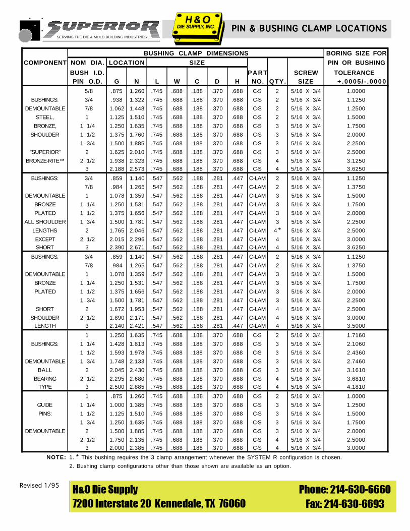
BUSHING CLAMP LOCATION SYSTEMSThree bushing clamp location systems are available forSuperior die sets. The LR, FB, and R Systems allow forvarious material feeding directions and should be con-sidered when ordering any die set. Special bushing clampconfigurations are available as an option.
WHEN ORDERING PLEASE SPECIFY:1. Bushing Clamp Part Number C-LAM or C-S2. Quantity
BUSHING CLAMPSBushing clamps are available in two styles. See chart forspecific die set component application. All slip fit demountableguide pins or bushings are supplied with clamps and sockethead cap screws.
(CLAMP NO. C-LAM)(CLAMP NO. C-LAM)(CLAMP NO. C-LAM)(CLAMP NO. C-LAM)(CLAMP NO. C-LAM) (CLAMP NO. C-S)(CLAMP NO. C-S)(CLAMP NO. C-S)(CLAMP NO. C-S)(CLAMP NO. C-S)
SERVING THE DIE & MOLD BUILDING INDUSTRIES
PIN & BUSHING CLAMP LOCATIONSPIN & BUSHING CLAMP LOCATIONSPIN & BUSHING CLAMP LOCATIONSPIN & BUSHING CLAMP LOCATIONSPIN & BUSHING CLAMP LOCATIONS
Revised 1/95 © 1990 Superior Die Set Corp.
BUSHING CLAMP DIMENSIONS BORING SIZE FOR
COMPONENT NOM DIA. LOCATION SIZE PIN OR BUSHING
BUSH I.D. PART SCREW TOLERANCE PIN O.D. G N L W C D H NO. QTY. SIZE + .0005 / - .0000
5/8 .875 1.260 .745 .688 .188 .370 .688 C-S 2 5/16 X 3/4 1.0000
BUSHINGS: 3/4 .938 1.322 .745 .688 .188 .370 .688 C-S 2 5/16 X 3/4 1.1250
DEMOUNTABLE 7/8 1.062 1.448 .745 .688 .188 .370 .688 C-S 2 5/16 X 3/4 1.2500
STEEL, 1 1.125 1.510 .745 .688 .188 .370 .688 C-S 2 5/16 X 3/4 1.5000
BRONZE, 1 1/4 1.250 1.635 .745 .688 .188 .370 .688 C-S 3 5/16 X 3/4 1.7500
SHOULDER 1 1/2 1.375 1.760 .745 .688 .188 .370 .688 C-S 3 5/16 X 3/4 2.0000
1 3/4 1.500 1.885 .745 .688 .188 .370 .688 C-S 3 5/16 X 3/4 2.2500
"SUPERIOR" 2 1.625 2.010 .745 .688 .188 .370 .688 C-S 3 5/16 X 3/4 2.5000
BRONZE-RITE™ 2 1/2 1.938 2.323 .745 .688 .188 .370 .688 C-S 4 5/16 X 3/4 3.12503 2.188 2.573 .745 .688 .188 .370 .688 C-S 4 5/16 X 3/4 3.6250
BUSHINGS: 3/4 .859 1.140 .547 .562 .188 .281 .447 C-LAM 2 5/16 X 3/4 1.1250
7/8 .984 1.265 .547 .562 .188 .281 .447 C-LAM 2 5/16 X 3/4 1.3750
DEMOUNTABLE 1 1.078 1.359 .547 .562 .188 .281 .447 C-LAM 3 5/16 X 3/4 1.5000
BRONZE 1 1/4 1.250 1.531 .547 .562 .188 .281 .447 C-LAM 3 5/16 X 3/4 1.7500
PLATED 1 1/2 1.375 1.656 .547 .562 .188 .281 .447 C-LAM 3 5/16 X 3/4 2.0000
ALL SHOULDER 1 3/4 1.500 1.781 .547 .562 .188 .281 .447 C-LAM 3 5/16 X 3/4 2.2500
LENGTHS 2 1.765 2.046 .547 .562 .188 .281 .447 C-LAM 4 * 5/16 X 3/4 2.5000
EXCEPT 2 1/2 2.015 2.296 .547 .562 .188 .281 .447 C-LAM 4 5/16 X 3/4 3.0000SHORT 3 2.390 2.671 .547 .562 .188 .281 .447 C-LAM 4 5/16 X 3/4 3.6250
BUSHINGS: 3/4 .859 1.140 .547 .562 .188 .281 .447 C-LAM 2 5/16 X 3/4 1.1250
7/8 .984 1.265 .547 .562 .188 .281 .447 C-LAM 2 5/16 X 3/4 1.3750
DEMOUNTABLE 1 1.078 1.359 .547 .562 .188 .281 .447 C-LAM 3 5/16 X 3/4 1.5000
BRONZE 1 1/4 1.250 1.531 .547 .562 .188 .281 .447 C-LAM 3 5/16 X 3/4 1.7500
PLATED 1 1/2 1.375 1.656 .547 .562 .188 .281 .447 C-LAM 3 5/16 X 3/4 2.0000
1 3/4 1.500 1.781 .547 .562 .188 .281 .447 C-LAM 3 5/16 X 3/4 2.2500
SHORT 2 1.672 1.953 .547 .562 .188 .281 .447 C-LAM 4 5/16 X 3/4 2.5000
SHOULDER 2 1/2 1.890 2.171 .547 .562 .188 .281 .447 C-LAM 4 5/16 X 3/4 3.0000LENGTH 3 2.140 2.421 .547 .562 .188 .281 .447 C-LAM 4 5/16 X 3/4 3.5000
1 1.250 1.635 .745 .688 .188 .370 .688 C-S 2 5/16 X 3/4 1.7160
BUSHINGS: 1 1/4 1.428 1.813 .745 .688 .188 .370 .688 C-S 3 5/16 X 3/4 2.1060
1 1/2 1.593 1.978 .745 .688 .188 .370 .688 C-S 3 5/16 X 3/4 2.4360
DEMOUNTABLE 1 3/4 1.748 2.133 .745 .688 .188 .370 .688 C-S 3 5/16 X 3/4 2.7460
BALL 2 2.045 2.430 .745 .688 .188 .370 .688 C-S 3 5/16 X 3/4 3.1610
BEARING 2 1/2 2.295 2.680 .745 .688 .188 .370 .688 C-S 4 5/16 X 3/4 3.6810TYPE 3 2.500 2.885 .745 .688 .188 .370 .688 C-S 4 5/16 X 3/4 4.1810
1 .875 1.260 .745 .688 .188 .370 .688 C-S 2 5/16 X 3/4 1.0000
GUIDE 1 1/4 1.000 1.385 .745 .688 .188 .370 .688 C-S 3 5/16 X 3/4 1.2500
PINS: 1 1/2 1.125 1.510 .745 .688 .188 .370 .688 C-S 3 5/16 X 3/4 1.5000
1 3/4 1.250 1.635 .745 .688 .188 .370 .688 C-S 3 5/16 X 3/4 1.7500
DEMOUNTABLE 2 1.500 1.885 .745 .688 .188 .370 .688 C-S 3 5/16 X 3/4 2.0000
2 1/2 1.750 2.135 .745 .688 .188 .370 .688 C-S 4 5/16 X 3/4 2.50003 2.000 2.385 .745 .688 .188 .370 .688 C-S 4 5/16 X 3/4 3.0000
NOTE: 1. * This bushing requires the 3 clamp arrangement whenever the SYSTEM R configuration is chosen.
2. Bushing clamp configurations other than those shown are available as an option.
SERVING THE DIE & MOLD BUILDING INDUSTRIES
STANDARD GUIDE PIN SIZESSTANDARD GUIDE PIN SIZESSTANDARD GUIDE PIN SIZESSTANDARD GUIDE PIN SIZESSTANDARD GUIDE PIN SIZES
© 1990 Superior Die Set Corp.
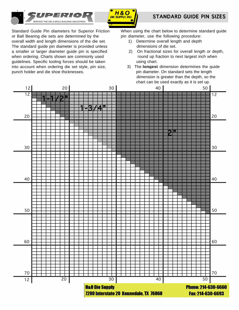
Standard Guide Pin diameters for Superior Frictionor Ball Bearing die sets are determined by theoverall width and length dimensions of the die set. The standard guide pin diameter is provided unless a smaller or larger diameter guide pin is specified when ordering. Charts shown are commonly used guidelines. Specific tooling forces should be taken into account when ordering die set style, pin size,punch holder and die shoe thicknesses.
When using the chart below to determine standard guidepin diameter, use the following procedure: 1) Determine overall length and depth dimensions of die set. 2) On fractional sizes for overall length or depth, round up fraction to next largest inch when using chart. 3) The longest dimension determines the guide pin diameter. On standard sets the length dimension is greater than the depth, so the chart can be used exactly as it is set up.
2”2”2”2”2”
1-1/2”1-1/2”1-1/2”1-1/2”1-1/2”1-3/4”1-3/4”1-3/4”1-3/4”1-3/4”
12 20 30 40 50
12
20
2020
12
12
30
30
30
40
40
40
50 50
50
60 60
7070
SERVING THE DIE & MOLD BUILDING INDUSTRIES
STANDARD GUIDE PIN SIZESSTANDARD GUIDE PIN SIZESSTANDARD GUIDE PIN SIZESSTANDARD GUIDE PIN SIZESSTANDARD GUIDE PIN SIZES
© 1990 Superior Die Set Corp.
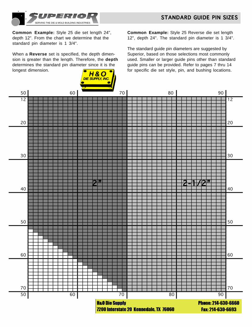
Common Example: Style 25 die set length 24",depth 12". From the chart we determine that the standard pin diameter is 1 3/4".
When a Reverse set is specified, the depth dimen-sion is greater than the length. Therefore, the depthdetermines the standard pin diameter since it is the longest dimension.
Common Example: Style 25 Reverse die set length12", depth 24". The standard pin diameter is 1 3/4".
The standard guide pin diameters are suggested bySuperior, based on those selections most commonly used. Smaller or larger guide pins other than standard guide pins can be provided. Refer to pages 7 thru 14 for specific die set style, pin, and bushing locations.
2”2”2”2”2”
50
2-1/2”2-1/2”2-1/2”2-1/2”2-1/2”
50 50
50
60
60
6060
70
70
70 70
80
80
90
90
20 20
30
4040
30
12 12
SERVING THE DIE & MOLD BUILDING INDUSTRIES
Revised 1/92 © 1990 Superior Die Set Corp.
INSPECTION SERVICESINSPECTION SERVICESINSPECTION SERVICESINSPECTION SERVICESINSPECTION SERVICES
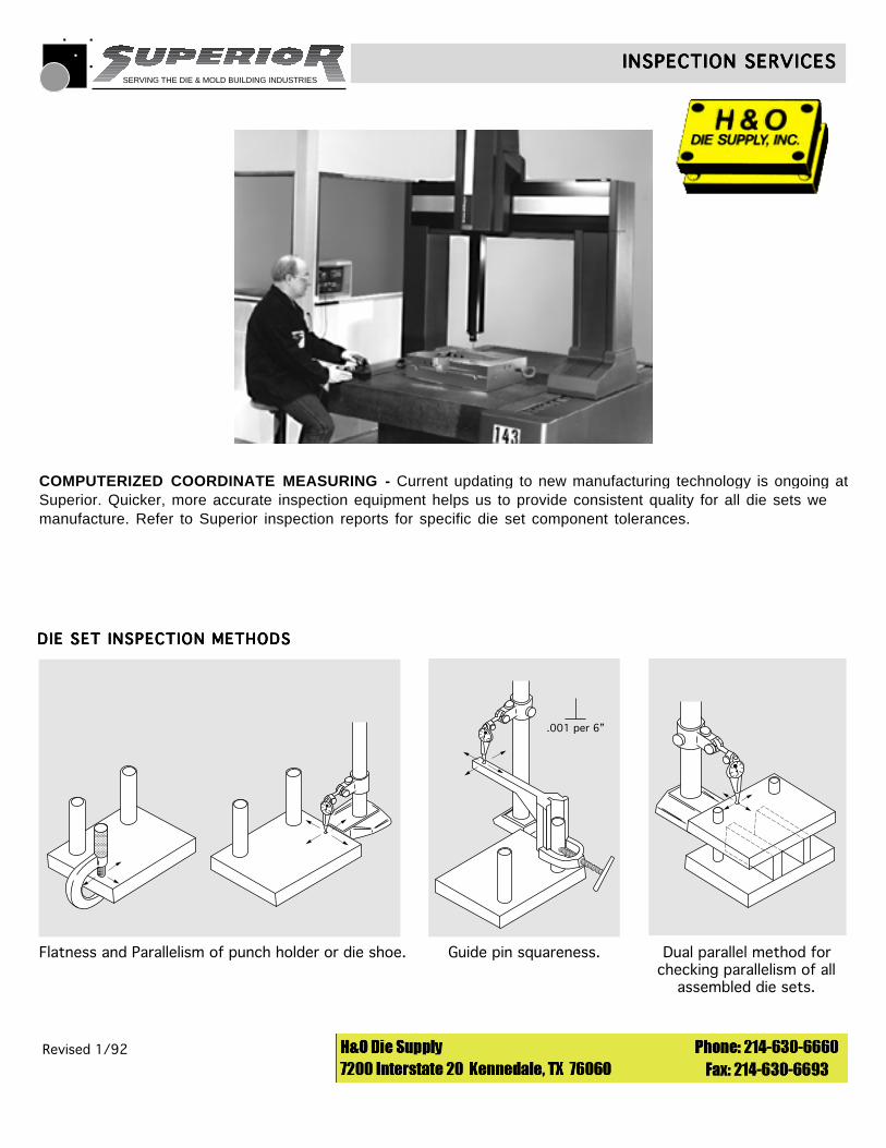
COMPUTERIZED COORDINATE MEASURING - Current updating to new manufacturing technology is ongoing atSuperior. Quicker, more accurate inspection equipment helps us to provide consistent quality for all die sets wemanufacture. Refer to Superior inspection reports for specific die set component tolerances.
������������������
DIE SET INSPECTION METHODSDIE SET INSPECTION METHODSDIE SET INSPECTION METHODSDIE SET INSPECTION METHODSDIE SET INSPECTION METHODS
Flatness and Parallelism of punch holder or die shoe.
.001 per 6”
Guide pin squareness. Dual parallel method forchecking parallelism of all
assembled die sets.
SERVING THE DIE & MOLD BUILDING INDUSTRIES
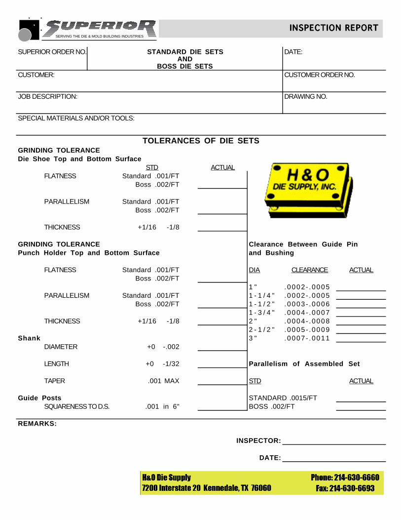
SUPERIOR ORDER NO. STANDARD DIE SETS DATE:AND
BOSS DIE SETSCUSTOMER: CUSTOMER ORDER NO.
JOB DESCRIPTION: DRAWING NO.
SPECIAL MATERIALS AND/OR TOOLS:
TOLERANCES OF DIE SETSGRINDING TOLERANCEDie Shoe Top and Bottom Surface
STD ACTUALFLATNESS Standard .001/FT
Boss .002/FT
PARALLELISM Standard .001/FTBoss .002/FT
THICKNESS +1/16 -1/8
GRINDING TOLERANCE Clearance Between Guide PinPunch Holder Top and Bottom Surface and Bushing
FLATNESS Standard .001/FT DIA CLEARANCE ACTUALBoss .002/FT
1 " .0002- .0005PARALLELISM Standard .001/FT 1 - 1 / 4 " .0002- .0005
Boss .002/FT 1 - 1 / 2 " .0003- .00061 - 3 / 4 " .0004- .0007
THICKNESS +1/16 -1/8 2 " .0004- .00082 - 1 / 2 " .0005- .0009
Shank 3 " .0007- .0011DIAMETER +0 -.002
LENGTH +0 -1/32 Parallelism of Assembled Set
TAPER .001 MAX STD ACTUAL
Guide Posts STANDARD .0015/FTSQUARENESS TO D.S. .001 in 6" BOSS .002/FT
REMARKS:
INSPECTOR:
DATE:
INSPECTION REPORTINSPECTION REPORTINSPECTION REPORTINSPECTION REPORTINSPECTION REPORT
© 1990 Superior Die Set Corp.
SERVING THE DIE & MOLD BUILDING INDUSTRIES
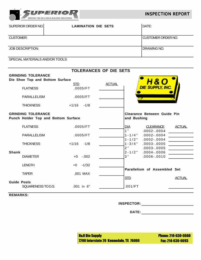
SUPERIOR ORDER NO. LAMINATION DIE SETS DATE:
CUSTOMER: CUSTOMER ORDER NO.
JOB DESCRIPTION: DRAWING NO.
SPECIAL MATERIALS AND/OR TOOLS:
TOLERANCES OF DIE SETSGRINDING TOLERANCEDie Shoe Top and Bottom Surface
STD ACTUALFLATNESS .0005/FT
PARALLELISM .0005/FT
THICKNESS +1/16 -1/8
GRINDING TOLERANCE Clearance Between Guide PinPunch Holder Top and Bottom Surface and Bushing
FLATNESS .0005/FT DIA CLEARANCE ACTUAL1 " .0002- .0004
PARALLELISM .0005/FT 1 - 1 / 4 " .0002- .00041 - 1 / 2 " .0002- .0004
THICKNESS +1/16 -1/8 1 - 3 / 4 " .0003- .00052 " .0003- .0005
Shank 2 - 1 / 2 " .0004- .0006DIAMETER +0 -.002 3 " .0006- .0010
LENGTH +0 -1/32Parallelism of Assembled Set
TAPER .001 MAXSTD ACTUAL
Guide PostsSQUARENESS TO D.S. .001 in 6" .001/FT
REMARKS:
INSPECTOR:
DATE:
INSPECTION REPORTINSPECTION REPORTINSPECTION REPORTINSPECTION REPORTINSPECTION REPORT
© 1990 Superior Die Set Corp.
SERVING THE DIE & MOLD BUILDING INDUSTRIES
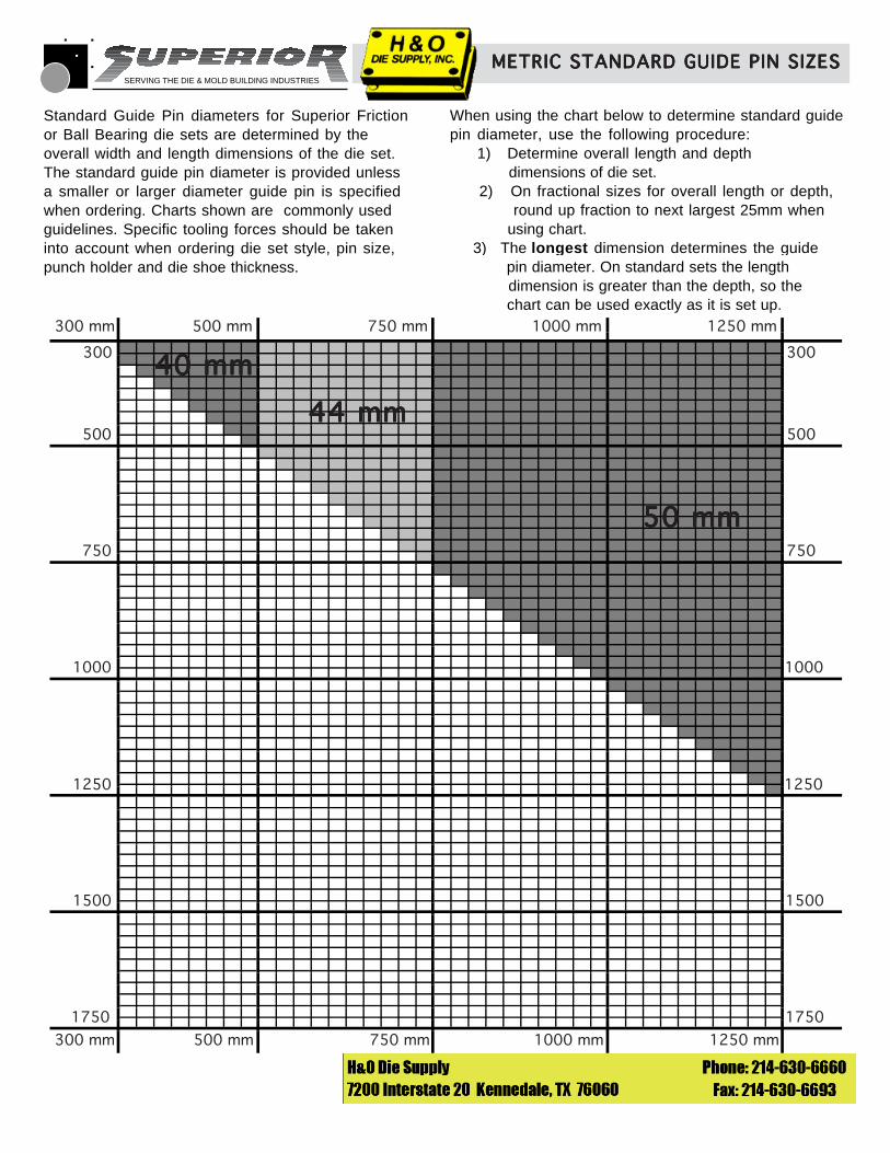
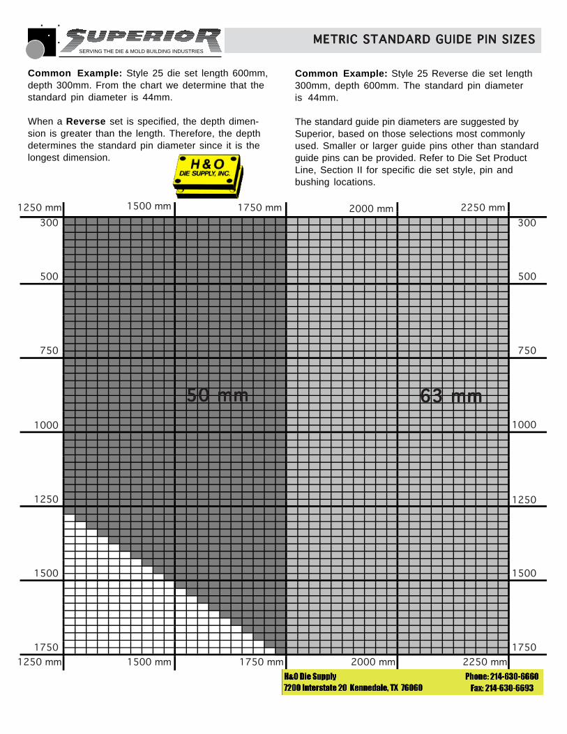
When using the chart below to determine standard guidepin diameter, use the following procedure: 1) Determine overall length and depth dimensions of die set. 2) On fractional sizes for overall length or depth, round up fraction to next largest 25mm when using chart. 3) The longest dimension determines the guide pin diameter. On standard sets the length dimension is greater than the depth, so the chart can be used exactly as it is set up.
© 1991 Superior Die Set Corp.
METRIC STANDARD GUIDE PIN SIZESMETRIC STANDARD GUIDE PIN SIZESMETRIC STANDARD GUIDE PIN SIZESMETRIC STANDARD GUIDE PIN SIZESMETRIC STANDARD GUIDE PIN SIZES
40 mm40 mm40 mm40 mm40 mm
44 mm44 mm44 mm44 mm44 mm
50 mm50 mm50 mm50 mm50 mm
Standard Guide Pin diameters for Superior Frictionor Ball Bearing die sets are determined by theoverall width and length dimensions of the die set.The standard guide pin diameter is provided unlessa smaller or larger diameter guide pin is specifiedwhen ordering. Charts shown are commonly usedguidelines. Specific tooling forces should be takeninto account when ordering die set style, pin size,punch holder and die shoe thickness.
300 mm 1000 mm750 mm500 mm 1250 mm
300 mm 500 mm 750 mm 1000 mm 1250 mm
300 300
500 500
750 750
1000 1000
1250 1250
1500 1500
1750 1750
SERVING THE DIE & MOLD BUILDING INDUSTRIES
© 1991 Superior Die Set Corp.
METRIC STANDARD GUIDE PIN SIZESMETRIC STANDARD GUIDE PIN SIZESMETRIC STANDARD GUIDE PIN SIZESMETRIC STANDARD GUIDE PIN SIZESMETRIC STANDARD GUIDE PIN SIZES
Common Example: Style 25 die set length 600mm, depth 300mm. From the chart we determine that thestandard pin diameter is 44mm.
When a Reverse set is specified, the depth dimen-sion is greater than the length. Therefore, the depthdetermines the standard pin diameter since it is thelongest dimension.
Common Example: Style 25 Reverse die set length300mm, depth 600mm. The standard pin diameteris 44mm.
The standard guide pin diameters are suggested bySuperior, based on those selections most commonlyused. Smaller or larger guide pins other than standardguide pins can be provided. Refer to Die Set ProductLine, Section II for specific die set style, pin and bushing locations.
50 mm50 mm50 mm50 mm50 mm 63 mm63 mm63 mm63 mm63 mm
1250 mm 1500 mm 1750 mm 2000 mm 2250 mm
300
500
750
1000
1250
1500
1750
300
500
750
1000
1250
1500
1750
1250 mm 1500 mm 1750 mm 2000 mm 2250 mm
SERVING THE DIE & MOLD BUILDING INDUSTRIES
© 1991 Superior Die Set Corp.
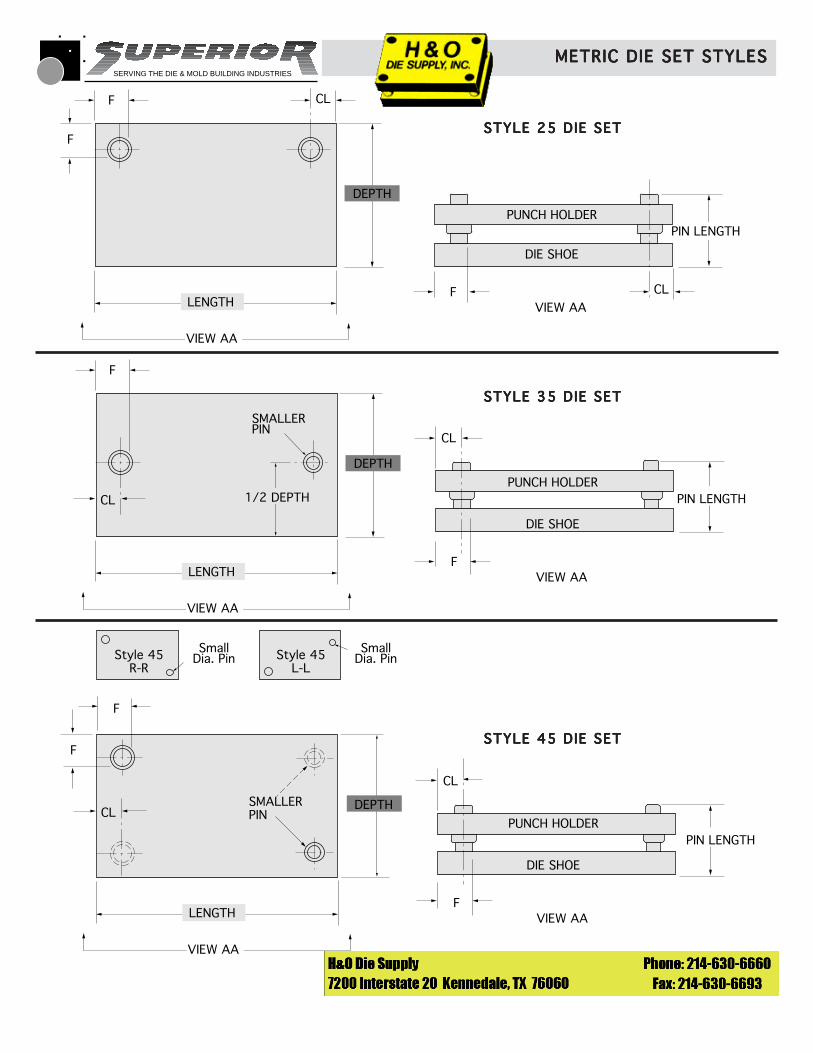
METRIC DIE SET STYLESMETRIC DIE SET STYLESMETRIC DIE SET STYLESMETRIC DIE SET STYLESMETRIC DIE SET STYLES
F
F CL
CL
DEPTH
VIEW AA
VIEW AALENGTH
PUNCH HOLDER
DIE SHOE
F
PIN LENGTH
F
CL
DEPTH
VIEW AA
VIEW AALENGTH
PUNCH HOLDER
DIE SHOE
F
PIN LENGTH
SMALLERPIN
CL
1/2 DEPTH
F
F
CL
VIEW AA
VIEW AALENGTH
PUNCH HOLDER
DIE SHOE
F
PIN LENGTH
SMALLERPIN
CL
Style 45R-R
SmallDia. Pin Style 45
L-L
SmallDia. Pin
DEPTH
STYLE 25 DIE SETSTYLE 25 DIE SETSTYLE 25 DIE SETSTYLE 25 DIE SETSTYLE 25 DIE SET
STYLE 35 DIE SETSTYLE 35 DIE SETSTYLE 35 DIE SETSTYLE 35 DIE SETSTYLE 35 DIE SET
STYLE 45 DIE SETSTYLE 45 DIE SETSTYLE 45 DIE SETSTYLE 45 DIE SETSTYLE 45 DIE SET
SERVING THE DIE & MOLD BUILDING INDUSTRIES
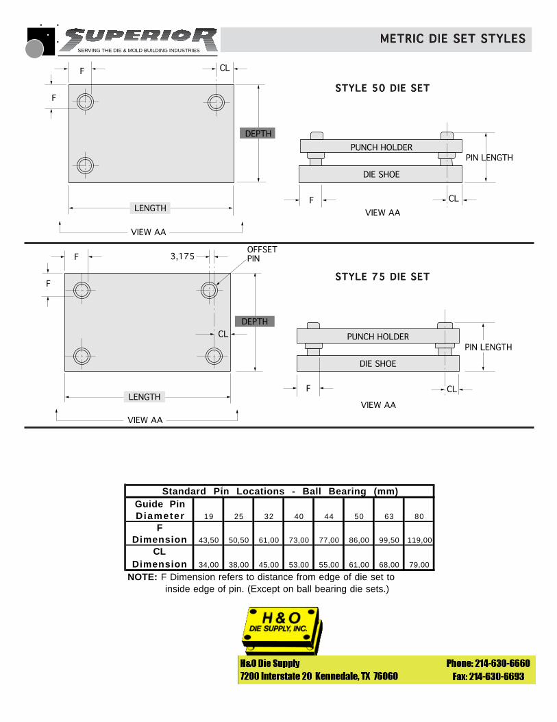
Standard Pin Locations - Ball Bearing (mm)Guide PinDiameter 19 25 32 40 44 50 63 80
F
Dimension 43,50 50,50 61,00 73,00 77,00 86,00 99,50 119,00
CLDimension 34,00 38,00 45,00 53,00 55,00 61,00 68,00 79,00
NOTE: F Dimension refers to distance from edge of die set to inside edge of pin. (Except on ball bearing die sets.)
© 1991 Superior Die Set Corp.
METRIC DIE SET STYLESMETRIC DIE SET STYLESMETRIC DIE SET STYLESMETRIC DIE SET STYLESMETRIC DIE SET STYLES
F
F CL
CL
DEPTH
VIEW AA
VIEW AALENGTH
PUNCH HOLDER
DIE SHOE
F
PIN LENGTH
F
F
CL
CL
DEPTH
VIEW AA
VIEW AALENGTH
PUNCH HOLDER
DIE SHOE
F
PIN LENGTH
OFFSETPIN3,175
STYLE 75 DIE SETSTYLE 75 DIE SETSTYLE 75 DIE SETSTYLE 75 DIE SETSTYLE 75 DIE SET
STYLE 50 DIE SETSTYLE 50 DIE SETSTYLE 50 DIE SETSTYLE 50 DIE SETSTYLE 50 DIE SET
SERVING THE DIE & MOLD BUILDING INDUSTRIES
© 1991 Superior Die Set Corp.
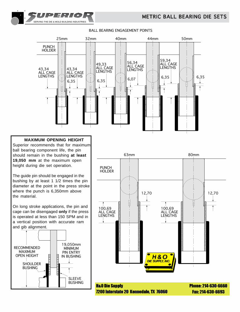
METRIC BALL BEARING DIE SETSMETRIC BALL BEARING DIE SETSMETRIC BALL BEARING DIE SETSMETRIC BALL BEARING DIE SETSMETRIC BALL BEARING DIE SETS
BALL BEARING ENGAGEMENT POINTS
25mm 32mm 40mm 44mm 50mm
PUNCHHOLDER
43,34ALL CAGELENGTHS
43,34ALL CAGELENGTHS
49,33ALL CAGELENGTHS
56,34ALL CAGELENGTHS
59,34ALL CAGELENGTHS
6,356,356,076,356,35
63mm 80mm
100,69ALL CAGELENGTHS
PUNCHHOLDER
100,69ALL CAGELENGTHS
12,70 12,70
19,050mmMINIMUM
PIN ENTRYIN BUSHING
SLEEVE BUSHING
SHOULDERBUSHING
RECOMMENDEDMAXIMUM
OPEN HEIGHT
MAXIMUM OPENING HEIGHTSuperior recommends that for maximumball bearing component life, the pinshould remain in the bushing at least19,050 mm at the maximum openheight during die set operation.
The guide pin should be engaged in thebushing by at least 1 1/2 times the pindiameter at the point in the press strokewhere the punch is 6,350mm abovethe material.
On long stroke applications, the pin andcage can be disengaged only if the pressis operated at less than 150 SPM and ina vertical position with accurate ramand gib alignment.
SERVING THE DIE & MOLD BUILDING INDUSTRIES
-
-
PUNCHHOLDER
DIESHOE
StraightGuide Pin
Demountable Guide Pin
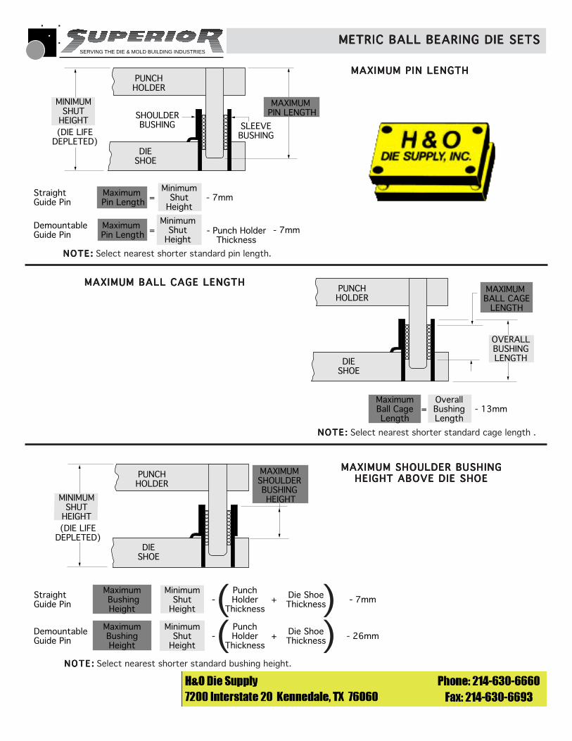
- 7mmMaximum BushingHeight
MaximumBushingHeight
MinimumShut
Height
MinimumShut
Height
MAXIMUMSHOULDERBUSHING HEIGHTMINIMUM
SHUTHEIGHT(DIE LIFE
DEPLETED)
Punch Holder
Thickness
Die ShoeThickness +
- 26mm Punch Holder
Thickness
Die ShoeThickness +
© 1991 Superior Die Set Corp.
METRIC BALL BEARING DIE SETSMETRIC BALL BEARING DIE SETSMETRIC BALL BEARING DIE SETSMETRIC BALL BEARING DIE SETSMETRIC BALL BEARING DIE SETS
MAXIMUM PIN LENGTHMAXIMUM PIN LENGTHMAXIMUM PIN LENGTHMAXIMUM PIN LENGTHMAXIMUM PIN LENGTH
PUNCHHOLDER
DIESHOE
- 13mmMaximumBall CageLength
OverallBushing Length
MAXIMUM BALL CAGE
LENGTH
OVERALLBUSHINGLENGTH
=
MAXIMUM BALL CAGE LENGTHMAXIMUM BALL CAGE LENGTHMAXIMUM BALL CAGE LENGTHMAXIMUM BALL CAGE LENGTHMAXIMUM BALL CAGE LENGTH
MAXIMUM SHOULDER BUSHINGMAXIMUM SHOULDER BUSHINGMAXIMUM SHOULDER BUSHINGMAXIMUM SHOULDER BUSHINGMAXIMUM SHOULDER BUSHINGHEIGHT ABOVE DIE SHOEHEIGHT ABOVE DIE SHOEHEIGHT ABOVE DIE SHOEHEIGHT ABOVE DIE SHOEHEIGHT ABOVE DIE SHOE
( )( )
PUNCHHOLDER
SHOULDERBUSHING
DIESHOE
SLEEVEBUSHING
StraightGuide Pin
Demountable Guide Pin
- 7mm
- 7mm- Punch HolderThickness
Maximum Pin Length
Maximum Pin Length
MinimumShut
Height
MinimumShut
Height
MAXIMUM PIN LENGTH
MINIMUMSHUT
HEIGHT
=
=
(DIE LIFEDEPLETED)
NOTE :NOTE :NOTE :NOTE :NOTE : Select nearest shorter standard pin length.
NOTE :NOTE :NOTE :NOTE :NOTE : Select nearest shorter standard cage length .
NOTE :NOTE :NOTE :NOTE :NOTE : Select nearest shorter standard bushing height.
SERVING THE DIE & MOLD BUILDING INDUSTRIES
© 1991 Superior Die Set Corp.
METRIC BALL BEARING DIE SETSMETRIC BALL BEARING DIE SETSMETRIC BALL BEARING DIE SETSMETRIC BALL BEARING DIE SETSMETRIC BALL BEARING DIE SETS
PUNCHHOLDER
DIESHOE
StraightGuide Pin
Demountable Guide Pin
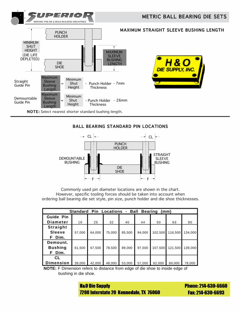
- 7mm
- Punch HolderThickness
- 26mm
MaximumSleeveBushing Length
MaximumSleeveBushing Length
MinimumShut
Height
MinimumShut
Height
MAXIMUMSLEEVEBUSHING LENGTH
MINIMUMSHUT
HEIGHT
- Punch HolderThickness
(DIE LIFEDEPLETED)
=
=
MAXIMUM STRAIGHT SLEEVE BUSHING LENGTHMAXIMUM STRAIGHT SLEEVE BUSHING LENGTHMAXIMUM STRAIGHT SLEEVE BUSHING LENGTHMAXIMUM STRAIGHT SLEEVE BUSHING LENGTHMAXIMUM STRAIGHT SLEEVE BUSHING LENGTH
NOTE:NOTE :NOTE :NOTE :NOTE : Select nearest shorter standard bushing length.
PUNCHHOLDER
DIESHOE
DEMOUNTABLEBUSHING
STRAIGHTSLEEVEBUSHING
CL CL
F F
BALL BEARING STANDARD PIN LOCATIONSBALL BEARING STANDARD PIN LOCATIONSBALL BEARING STANDARD PIN LOCATIONSBALL BEARING STANDARD PIN LOCATIONSBALL BEARING STANDARD PIN LOCATIONS
Commonly used pin diameter locations are shown in the chart.However, specific tooling forces should be taken into account when
ordering ball bearing die set style, pin size, punch holder and die shoe thicknesses.
Standard Pin Locations - Ball Bearing (mm)Guide PinDiameter 19 25 32 40 44 50 63 80
Stra ightSleeve 57,000 64,000 75,000 85,500 94,000 102,500 116,500 134,000
F Dim.Demount.Bushing 61,500 67,500 78,500 89,000 97,500 107,500 121,500 139,000
F Dim.CL
Dimension 39,000 42,000 48,000 53,000 57,000 62,000 69,000 78,000
NOTE: F Dimension refers to distance from edge of die shoe to inside edge of bushing in die shoe.
SERVING THE DIE & MOLD BUILDING INDUSTRIES
PUNCHHOLDER
DIESHOE
BUSHING LENGTHABOVE DS
MAXIMUMBALL CAGE
LENGTH MAXIMUMPIN LENGTH
PIN LENGTHBELOW PH
MINIMUMSHUT HEIGHT
(DIE LIFEDEPLETED)
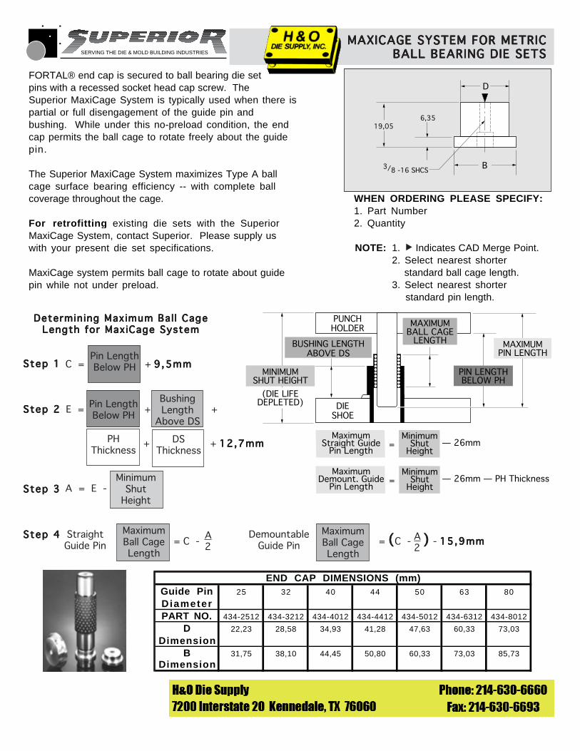
MaximumStraight Guide
Pin Length
MinimumShut
Height= — 26mm
MaximumDemount. Guide
Pin Length
MinimumShut
Height= — 26mm — PH Thickness
WHEN ORDERING PLEASE SPECIFY:1. Part Number2. Quantity
NOTE: 1. Indicates CAD Merge Point.2. Select nearest shorter standard ball cage length.3. Select nearest shorter standard pin length.
MAXICAGE SYSTEM FOR METRICMAXICAGE SYSTEM FOR METRICMAXICAGE SYSTEM FOR METRICMAXICAGE SYSTEM FOR METRICMAXICAGE SYSTEM FOR METRICBALL BEARING DIE SETSBALL BEARING DIE SETSBALL BEARING DIE SETSBALL BEARING DIE SETSBALL BEARING DIE SETS
© 1993 Superior Die Set Corp.
▲
Determining Maximum Bal l CageDetermining Maximum Bal l CageDetermining Maximum Bal l CageDetermining Maximum Bal l CageDetermining Maximum Bal l CageLength for MaxiCage SystemLength for MaxiCage SystemLength for MaxiCage SystemLength for MaxiCage SystemLength for MaxiCage System
Step 1Step 1Step 1Step 1Step 1
Step 2Step 2Step 2Step 2Step 2
Step 3Step 3Step 3Step 3Step 3
Step 4Step 4Step 4Step 4Step 4 MaximumBall CageLength
= C -A2
StraightGuide Pin
DemountableGuide Pin
MaximumBall CageLength
= C - - 15,9mm15,9mm15,9mm15,9mm15,9mm( )( )( )( )( )A2
MinimumShut
HeightA = E -
Pin LengthBelow PHC = + 9,5mm9,5mm9,5mm9,5mm9,5mm
BushingLength
Above DS
Pin LengthBelow PH
E = + +
+ + 12,7mm12,7mm12,7mm12,7mm12,7mmDSThickness
PHThickness
19,056,35
D
B3/8 -16 SHCS
FORTAL® end cap is secured to ball bearing die setpins with a recessed socket head cap screw. TheSuperior MaxiCage System is typically used when there ispartial or full disengagement of the guide pin andbushing. While under this no-preload condition, the endcap permits the ball cage to rotate freely about the guidepin.
The Superior MaxiCage System maximizes Type A ballcage surface bearing efficiency -- with complete ballcoverage throughout the cage.
For retrofitting existing die sets with the SuperiorMaxiCage System, contact Superior. Please supply uswith your present die set specifications.
MaxiCage system permits ball cage to rotate about guidepin while not under preload.
END CAP DIMENSIONS (mm)Guide Pin 25 32 40 44 50 63 80
DiameterPART NO. 434-2512 434-3212 434-4012 434-4412 434-5012 434-6312 434-8012
D 22,23 28,58 34,93 41,28 47,63 60,33 73,03
DimensionB 31,75 38,10 44,45 50,80 60,33 73,03 85,73
Dimension
SERVING THE DIE & MOLD BUILDING INDUSTRIES
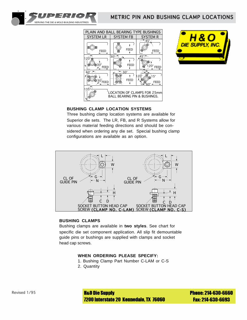
BUSHING CLAMPSBushing clamps are available in two styles. See chart forspecific die set component application. All slip fit demountableguide pins or bushings are supplied with clamps and sockethead cap screws.
PLAIN AND BALL BEARING TYPE BUSHINGSSYSTEM LR SYSTEM FB SYSTEM R
FEED
FEED
FEED
FEED FEED
45°
30°
120°30°
FEED
45°
120°FEED
60°
30° FEED60°
15°30°
FEED120°
135°LOCATION OF CLAMPS FOR 25mmBALL BEARING PIN & BUSHINGS.
Revised 1/95 © 1993 Superior Die Set Corp.
METRIC PIN AND BUSHING CLAMP LOCATIONSMETRIC PIN AND BUSHING CLAMP LOCATIONSMETRIC PIN AND BUSHING CLAMP LOCATIONSMETRIC PIN AND BUSHING CLAMP LOCATIONSMETRIC PIN AND BUSHING CLAMP LOCATIONS
BUSHING CLAMP LOCATION SYSTEMSThree bushing clamp location systems are available forSuperior die sets. The LR, FB, and R Systems allow forvarious material feeding directions and should be con-sidered when ordering any die set. Special bushing clampconfigurations are available as an option.
WHEN ORDERING PLEASE SPECIFY:1. Bushing Clamp Part Number C-LAM or C-S2. Quantity
GN
L
W
CL OFGUIDE PIN
GN
L
W
CL OFGUIDE PIN
C D
H
C D
H
SOCKET BUTTON HEAD CAPSCREW
SOCKET BUTTON HEAD CAPSCREW (CLAMP NO. C-LAM)(CLAMP NO. C-LAM)(CLAMP NO. C-LAM)(CLAMP NO. C-LAM)(CLAMP NO. C-LAM) (CLAMP NO. C-S)(CLAMP NO. C-S)(CLAMP NO. C-S)(CLAMP NO. C-S)(CLAMP NO. C-S)
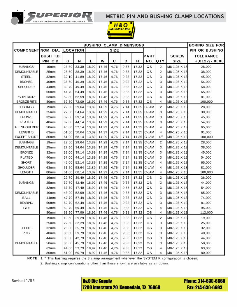
SERVING THE DIE & MOLD BUILDING INDUSTRIES
Revised 1/95 © 1993 Superior Die Set Corp.
METRIC PIN AND BUSHING CLAMP LOCATIONSMETRIC PIN AND BUSHING CLAMP LOCATIONSMETRIC PIN AND BUSHING CLAMP LOCATIONSMETRIC PIN AND BUSHING CLAMP LOCATIONSMETRIC PIN AND BUSHING CLAMP LOCATIONS
BUSHING CLAMP DIMENSIONS BORING SIZE FORCOMPONENT NOM DIA. LOCATION SIZE PIN OR BUSHING
BUSH I.D. PART SCREW TOLERANCEPIN O.D. G N L W C D H NO. QTY. SIZE + ,0127 / - , 0000
BUSHINGS: 19mm 23,60 33,39 18,92 17,46 4,76 9,38 17,32 C-S 2 M8-1.25 X 18 28,000
DEMOUNTABLE 25mm 28,60 38,39 18,92 17,46 4,76 9,38 17,32 C-S 2 M8-1.25 X 18 38,000
STEEL, 32mm 32,10 41,89 18,92 17,46 4,76 9,38 17,32 C-S 3 M8-1.25 X 18 45,000
BRONZE, 40mm 36,60 46,39 18,92 17,46 4,76 9,38 17,32 C-S 3 M8-1.25 X 18 54,000
SHOULDER 44mm 39,70 49,49 18,92 17,46 4,76 9,38 17,32 C-S 3 M8-1.25 X 18 58,000
50mm 44,70 54,49 18,92 17,46 4,76 9,38 17,32 C-S 3 M8-1.25 X 18 65,000
"SUPERIOR" 63mm 52,80 62,59 18,92 17,46 4,76 9,38 17,32 C-S 4 M8-1.25 X 18 81,000BRONZE-RITE 80mm 62,30 72,09 18,92 17,46 4,76 9,38 17,32 C-S 4 M8-1.25 X 18 100,000
BUSHINGS: 19mm 22,50 29,64 13,89 14,29 4,76 7,14 11,35 C-LAM 2 M8-1.25 X 18 28,000
DEMOUNTABLE 25mm 27,50 34,64 13,89 14,29 4,76 7,14 11,35 C-LAM 3 M8-1.25 X 18 38,000
BRONZE 32mm 32,00 39,14 13,89 14,29 4,76 7,14 11,35 C-LAM 3 M8-1.25 X 18 45,000
PLATED 40mm 37,00 44,14 13,89 14,29 4,76 7,14 11,35 C-LAM 3 M8-1.25 X 18 54,000
ALL SHOULDER 50mm 45,00 52,14 13,89 14,29 4,76 7,14 11,35 C-LAM 4 M8-1.25 X 18 65,000
LENGTHS 63mm 51,50 58,64 13,89 14,29 4,76 7,14 11,35 C-LAM 4 M8-1.25 X 18 81,000EXCEPT SHORT 80mm 61,00 68,14 13,89 14,29 4,76 7,14 11,35 C-LAM 4 * M8-1.25 X 18 100,000
BUSHINGS: 19mm 22,50 29,64 13,89 14,29 4,76 7,14 11,35 C-LAM 2 M8-1.25 X 18 28,000
DEMOUNTABLE 25mm 27,50 34,64 13,89 14,29 4,76 7,14 11,35 C-LAM 3 M8-1.25 X 18 38,000
BRONZE 32mm 32,00 39,14 13,89 14,29 4,76 7,14 11,35 C-LAM 3 M8-1.25 X 18 45,000
PLATED 40mm 37,00 44,14 13,89 14,29 4,76 7,14 11,35 C-LAM 3 M8-1.25 X 18 54,000
SHORT 50mm 45,00 52,14 13,89 14,29 4,76 7,14 11,35 C-LAM 4 M8-1.25 X 18 65,000
SHOULDER 63mm 51,50 58,64 13,89 14,29 4,76 7,14 11,35 C-LAM 4 M8-1.25 X 18 81,000LENGTH 80mm 61,00 68,14 13,89 14,29 4,76 7,14 11,35 C-LAM 4 M8-1.25 X 18 100,000
19mm 29,70 39,49 18,92 17,46 4,76 9,38 17,32 C-S 2 M8-1.25 X 18 36,000
BUSHINGS: 25mm 32,70 42,49 18,92 17,46 4,76 9,38 17,32 C-S 2 M8-1.25 X 18 44,000
32mm 37,70 47,49 18,92 17,46 4,76 9,38 17,32 C-S 3 M8-1.25 X 18 54,000
DEMOUNTABLE 40mm 43,20 52,99 18,92 17,46 4,76 9,38 17,32 C-S 3 M8-1.25 X 18 65,000
BALL 44mm 47,70 57,49 18,92 17,46 4,76 9,38 17,32 C-S 3 M8-1.25 X 18 74,000
BEARING 50mm 52,70 62,49 18,92 17,46 4,76 9,38 17,32 C-S 3 M8-1.25 X 18 81,000
TYPE 63mm 59,70 69,49 18,92 17,46 4,76 9,38 17,32 C-S 4 M8-1.25 X 18 95,00080mm 68,20 77,99 18,92 17,46 4,76 9,38 17,32 C-S 4 M8-1.25 X 18 112,000
19mm 19,50 29,29 18,92 17,46 4,76 9,38 17,32 C-S 2 M8-1.25 X 18 19,000
25mm 22,50 32,29 18,92 17,46 4,76 9,38 17,32 C-S 3 M8-1.25 X 18 25,000
GUIDE 32mm 26,00 35,79 18,92 17,46 4,76 9,38 17,32 C-S 3 M8-1.25 X 18 32,000
PINS: 40mm 30,00 39,79 18,92 17,46 4,76 9,38 17,32 C-S 3 M8-1.25 X 18 40,000
44mm 33,00 42,79 18,92 17,46 4,76 9,38 17,32 C-S 3 M8-1.25 X 18 44,000
DEMOUNTABLE 50mm 36,00 45,79 18,92 17,46 4,76 9,38 17,32 C-S 3 M8-1.25 X 18 50,000
63mm 44,00 53,79 18,92 17,46 4,76 9,38 17,32 C-S 4 M8-1.25 X 18 63,00080mm 51,00 60,79 18,92 17,46 4,76 9,38 17,32 C-S 4 M8-1.25 X 18 80,000
NOTE: 1. * This bushing requires the 3 clamp arrangement whenever the SYSTEM R configuration is chosen.
2. Bushing clamp configurations other than those shown are available as an option.
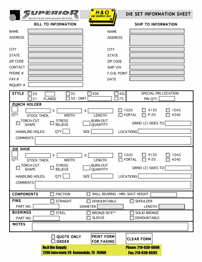
SERVING THE DIE & MOLD BUILDING INDUSTRIES
QUOTE ONLYQUOTE ONLYQUOTE ONLYQUOTE ONLYQUOTE ONLY
ORDERORDERORDERORDERORDER
DIE SET INFORMATION SHEETDIE SET INFORMATION SHEETDIE SET INFORMATION SHEETDIE SET INFORMATION SHEETDIE SET INFORMATION SHEET
BILL TO INFORMATIONBILL TO INFORMATIONBILL TO INFORMATIONBILL TO INFORMATIONBILL TO INFORMATION SHIP TO INFORMATIONSHIP TO INFORMATIONSHIP TO INFORMATIONSHIP TO INFORMATIONSHIP TO INFORMATION
NAME
ADDRESS
CITY
STATE
ZIP CODE
CONTACT
PHONE #
FAX #
INQUIRY #
NAME
ADDRESS
CITY
STATE
ZIP CODE
SHIP VIA
F.O.B. POINT
DATE
PRINT FORMPRINT FORMPRINT FORMPRINT FORMPRINT FORM
FOR FAXINGFOR FAXINGFOR FAXINGFOR FAXINGFOR FAXINGCLEAR FORMCLEAR FORMCLEAR FORMCLEAR FORMCLEAR FORM
STYLESTYLESTYLESTYLESTYLE SPECIAL PIN LOCATION
PIN QTY.
QTY1020FORTAL
4130P-20
10454340
TORCH-CUTSHAPE
STRESSRELIEVE
BURN-OUTQUANTITY GRIND (2) SIDES TO
X X
HANDLING HOLES:
STOCK THICK. WIDTH LENGTH
PUNCH HOLDERPUNCH HOLDERPUNCH HOLDERPUNCH HOLDERPUNCH HOLDER
COMMENTS
LOCATIONSSIZEQTY
QTY1020FORTAL
4130P-20
10454340
TORCH-CUTSHAPE
STRESSRELIEVE
BURN-OUTQUANTITY GRIND (2) SIDES TO
X X
HANDLING HOLES:
STOCK THICK. WIDTH LENGTH
DIE SHOEDIE SHOEDIE SHOEDIE SHOEDIE SHOE
COMMENTS
LOCATIONSSIZEQTY
FRICTION BALL BEARING - MIN. SHUT HEIGHTCOMPONENTSCOMPONENTSCOMPONENTSCOMPONENTSCOMPONENTS
NOTESNOTESNOTESNOTESNOTES
LENGTH
P INSP INSP INSP INSP INS SHOULDERSTRAIGHT DEMOUNTABLE
DIAMETERPART NO.
BUSHINGSBUSHINGSBUSHINGSBUSHINGSBUSHINGS SOLID BRONZESTEEL BRONZE-RITE™
PART NO. SLEEVE DEMOUNTABLE
3550 : OMIT
45L
7520
21
45R
FLANGE