Embed Size (px)
Citation preview

Pascal mold die change system

Pascal mold change system
Die leveler
Quick locating system
Die set ter
Octagonal locate r ing
Hydraulic clamp
Air clamp
Operation panel & Control box
Operation panel ELC-B
Mag clamp
Operation panel & Control box
DD mag clamp
Mag clamp for ver tical IMM
Mag clamp for two-color IMM
model HCM(For medium and large-sized IMM)
Mag clamp
Control unit
Positioning device
Hydraulic clamp
Air clamp
new
new
page → 4
page → 10
page → 64
page → 14
page → 16
page → 18
page → 22
page → 28
page → 30
page → 12
page → 12
page → 32
page → 40
page → 26
2

Pascal mold change system
Auto coupler
C&C coupler
Multi coupler
Easy ejector rod
Ball lock ejector rod
Accessory
Auto coupler
Multi coupler
Mold changer
Mold rotator
Robot toolchanger
N2 gas spring
model SMRRolling type
model SMFFlat type Die rotator with
separation
improvement of Mold change Step1
new
page → 42
page → 45
page → 46
page → 50
page → 52
page → 56
page → 66
page → 67
page → 62
3

10,000kN(1,000ton) IMM Vertical loading Mag clamp
Clamps the mold instantly with a super strong permanent magnet.
Pascal mag clamp
Pascal mag clamp is a mold clamp system for injection molding machines that clamps the mold
with powerful magnetic force. The clamp plate is one set of two plates for movable platen and fixed platen sides.
Mag c lamp
44
Displacementdetection core
Central magnet core
Plate mount screw Clamp plate for fixed platen
Clamp platefor movable platen Magnet core
Mold fall protection hook
Mold fall protection hook(length adjustable)model MGR
With a easily adjustable chain
Die stopperDie stopper
Die stopper
It can positively prevent the die-fall accident due to the molddisplacement or nozzle or ejector touch.
Mold fall protection hook
Mold fall protection hook
Mag c lamp
Clamping mold instantly
(0.5-4.5 sec)
No needto unify themold sizes
Mold displacement
Detectable
55

Neodymium magnet
Alnico magnet
Electromagnetic coil inverts
Magnet core
Clamp plateMold plate
Lines of magnetic flux
Effective height of magnetic flux: Approx 20mm
Plate thickness35mm, 50mm, 52mm
Mold Mold
Super strong permanentmagnet
Polarity is invertedby electromagnetic coil
The polarity of alnico magnet
adheres the mold strongly
Electromagnetic coil is energized for in 0.5 sec.
Polarity of alnico magnet is inverted.
Neodymium magnet and alnico magnet becomehomopolar
Magnet core becomes a strong magnet to clampthe mold.
1
2
3
4
1
2
3
Electromagnetic coil is energized in 0.5 sec.
Polarity of alnico magnet is inverted.
Magnetic flux of neodymium and alnicois not emitted from the surface of themagnet core so that the mold can be unclamped.
Displacement or lifting of the mold can be detected by the electromagnetic coil in the magnet core located near the center of clamp plates.When the mold moves, these coils detect an induction current signal.
Normal clamping status When the mold moves① Displacement or lifting
② Flux changes due to displacement or lifting
③ Induction current is generated.
Mold center area is not so much influenced by the openings or grooves and mold displacement or l i ft ing can securely be detected.
Ex. Mold plate with openings or cutouts
N NS N NS
NS
SN
NS
SN
Stable magnetic flux
Electromagnetic coil
Displacementdetection core
Mold is in close contact with magnet core
MoldDisplace-mentDisplace-ment
Mag c lamp
Structure and function
Displacement detection system(standard)
● Clamp(Magnetized) ● Unclamp(Demagnetized)
66

Mag c lamp
Specifications
● Locate ring(fixed side only)
● Mold fall protection block(movable side only)
● Operation panel model ESMD
● Control box model EMGD
● Control cables
● Interlock
Accessories Option
● Non standard voltage arrangement(50/60Hz)
● High temperature
● Rust proof, polish arrangement for clamp plate
● Mold fall protection hook model MGR
(movable side & fixed side)
● Additional magnet core
● Special core layout
● Horizontal loading arrangement
● DD mag clamp
● Proximity sensor to detect the mold cohered
・AC380V ±5%
・AC440V ±5%
・AC480V ±5%
・0 ~ 150℃
・0 ~ 180℃
● Additional tap holes are required in the middle of machine platens.● Operating temperature indicates the temperature on the surface of the clamp plate.
Model MG□
Clamping force(per one magnet core)
Thin-model35mm
32×100mm 3.43kN
50× 50mm 2.45kN
100×100mm 7.84kN
Standard50,52mm
70× 70mm 7.35kN
75× 75mm 7.84kN
115×115mm 15.68kN
Operating temperature ℃ 0 ~ 80 (0 ~ 150 or 0 ~ 180 for heat proof type)
Magnetic flux height mm 20 (mold plate material SS400)
Power voltage AC200 / 220V ±5% (50/60Hz)
Applicable machine For general injection molding machine
Plate mounting method by screws utilizing the tap holes on the machine platens
Displacement detection system(movable side & fixed side) Include
77

Clamp plate for movable platen
Operation panel for magnet clamp
Mold fall protection hook
Clamp plate for fixed platen
There are interferencesThe flexibility of mold design
has been improved
Conventional Mag clamp
Automatic clamp
MoldMold
Mag c lamp
● No need to unify the mold sizes.(Note that clamping force varies according to the size of mold plate.)● No need to secure the space to mount the retrofitted clamps on the platens and the mold size will not be restricted by the clamp space.
Vertical loading
88

Mag clamp
Conventional
Spacer
Mold plate
Mag clamp
Mold(Big)
Mold(Small) Mold(Small)
Mold(Big)
Mold(Small)
Mold(Small)
The reproduction of mold plateis required
Clamp plate for movable platen
Operation panel for magnet clamp
Positioning cylinder
Mold changer
Clamp plate for fixed platen
A spacer is attachedTo enable the mold to change whichever horizontal or vertical
Mag c lamp
● Even if the mold height is not unified, the horizontal loading is feasible by simply attaching the spacer or a riser.
Horizontal loading
99

100 3530
150
Compact and user-friendly operation panel exclusively designed for magnetic clamp.
It is mountable on IMM or wall of IMM utilizing the tap holes at the rear side. (M4 bolts x 4 accessories)
[ For vertical loading ] [ For horizontal loading ]
Operation panel
kg 0.6 0.6
Model ESMD-A ESMD-B
Loading direction
Weight
Horizontal loadingVertical loading
model ESMD-A model ESMD-B
Mag c lamp
1010

350 20050
400
● During molding production
If the mold is displaced or detached from the clamp plate, the molding machine is immediately stopped by the displacement detection function.
model EMGD
Control box
kg
Model EMGD
Weight 25 ~ 80
*Size for model EMGD-A2J2
Safety interlocks listed below are built in the electric control circuit for mold change operation.
● When changing a mold, Mag clamp operation is feasible only when the following conditions are prepared.
Mag clamp : ①Mold change mode
IMM : ②Set-up(or manual)mode, ③Nozzle retracted, ④Ejector retracted, ⑤Platen closed-end, ⑥Safety door closed
Regarding the condition of IMM side such as ②, ③ and ⑤, it can be confirmed with LED lamp on operation panel.
Interlock
Mag c lamp
1111
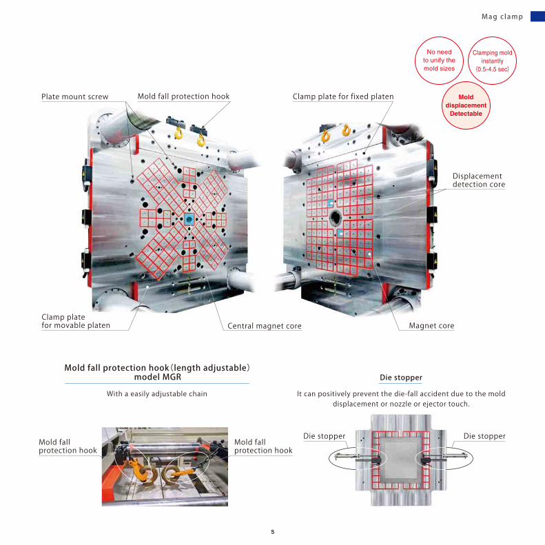
As for DD mag clamp, the status indicator is added to the control box.
Display panel control panel built-in type
Display panel additional type(operation side)
The clamp with DD sensor which can numerically check the mold. It can detect the clamp force
decrease caused by heat, mold base material and a clearance between the mold and magnet core.
Gap detection
Normal clamping status
The sensor indicates AA which means the mold has adequate size, material and temperature are appropriate to clamp and there is no gap between the magnetic surface and mold.
Normal clamping status
Smart sensor checks the mold
DD mag clamp
Machine platen
Magnet core
DD Mag clamp
Mold
Mag c lamp
1212

93 85 96 82
75 6975
Simply type of material or mold temperature does not make the clamping force decrease lowerthan 80% however the value goes down due to the force decrease.
The sensor output abnormal signal when clamp force decreases more than 20% due to gap or clearance.
Dents and Foreignmaterial biting
Cutout(including screw hole)
Clamp force decreasesdue to the material thatare not easily magnetized
Mold becomes hot
Clamp force decrease due to the gapDetect too smal l mold
Clamp force decrease due tothe material that are not easi ly magnetized.
Clamp force decreasedue to a c learance
Normal Normal
Size detection
Material detection
Clamp force decreases due to the mold heat-up
High temperature detection
Gap detection Clearance detection
Minimum moldsize requiredto clamp
Mag c lamp
1313

750kN(75ton)Vertical IMM(fixed table) Mag clamp for upper mold
Mold(large size)
Mold(small size)
Displacementdetection core
Upper clamp plate
Magnet core
No need to unifythe mold sizes
Eject pin PAT.
Magnet core
Plate mount screw
Upper clamp plate
Displacementdetection core
Mag clamp for vertical IMM
Mountable for upper d ie only
Mag c lamp
1414

The introduction of Mag clamp in the vertical IMMeliminates bolting job (temporary tightening, retightening) in a limited space of the machine
and realizes shortening the set up time considerably.
No need to unifythe mold sizes
750kN(75ton)Vertical IMM(Rotary) Lower Mag clamp
Magnet core
Displacementdetection core
Rollers
Lower clamp plate Positioning block
Mold(large size)
Mold(small size)
Displacementdetection core
Rollers
Lower clamp plate
Guide block
Magnet core
Mag c lamp
1515

Mag clamp for two-color IMM
6,000kN(600ton) Two-color IMM Vertical loading Mag clamp
in 250 ton class
45minShortening
the set up time to Molddisplacement
Detectable
Mag c lamp
1616

It takes a long time for an operator to screw or unscrew the bolts many times at a narrow space in a machine.
Mold changing time : 60min (250 ton class)
The moving picture of mold change operation for two-color IMM with mag clamp is being uploaded in Pascal web site.
Hand tightening method
Clamp instantly by magnetic force with no work in the machine.
Mold changing time:15min (250 ton class)
Mag clamp
●Easy to drop tools. ● No visual● Limited power exertion.●Need to move to operation / non-operation side to install / remove bolts.
● Install bolts many times.
● Simply use the operation panel to clamp and unclamp the mold.
● Mold changing is done in only 15 minutes.● With no work in the machine.
Mag c lamp
1717

Hydraulic clamp
4,500kN(450ton) IMM Vertical loading Hydraulic clamp, slidable type TYA
Hyd.
Hydraul ic c lamp
1818

16,000kN(1,600ton)IMM Vertical loading Hydraulic clamp, automatic slidable type TYC-Z
3,500kN(350ton)IMM Vertical loading Hydraulic clamp, T-slot-less slidable type TYA-M
Hydraul ic c lamp
1919

Long stroke typeLong stroke typeStandard type
Slidable clamp & Die leveler Automatic slidable clamp & Die leveler
Clamp TYA
Guide block
Die leveler
T-slot
Mold
Clamp TYC-Z
Air cylinder
Guide block
Die leveler
T-slot
Mold
PAT.P.
Pin engagement groove
Lever spacer
Pin
Magnet Install the spacer tightly on the clamp body.
The spacer is pulled up at unclamping.
model TYA model TYJmodel TYB
T-slotted manual slide type of clampSlidable type line-up
The max. 5mm (in case of using a lever spacer, max. 15mm) of dimensional variation can be absorbed.
The max.10mm lever stroke can accommodate dimensional variation of clamping height.
There is a risk of mismounting the wrong size of mold in case of choosing long stroke type of clamp.!
model TYC-R
model TYC-ZSlide direction:Horizontal
Slide direction:Vertical
Automatic slidable typeAutomatic slidable clamp with air cylinder. It enables to shorten the mold change time.
Hyd.
Hydraul ic c lamp
2020

Clamp, T-slot- less slidable type & Die leveler Bolted type clamp & Positioning block
Side block
Clamp TYA-M
Guide block
Die leveler
Mold
Clamp TME
Guide block
Positioning block
Mold
T-slot-less slidable /automatic slidable typeManual slide type of clamp with a sideblock (T-slotted block). It enables the clamp to slide it manually even if machine platens do not have T-slots.
Bolted typeBolted type of clamp.
model TMEFor small andmedium-sized IMM
model TKBFor medium andlarge-sized IMM
model TYA-M
Hydraul ic c lamp
2121

2,200kN(220ton)IMM Vertical loading Air clamp, slidable type TLC
AirAir clamp
Air c lamp
2222

1,100kN(110ton)IMM Vertical loading Air clamp, automatic slidable type TLC-Z
400kN(40ton)Vertical IMM Air clamp, T-slot-less slidable type TLA-M
Air c lamp
2323

model TLC
model TLC-Z
model TLC-R
T-slotted manual slide type of clamp
Slidable type Automatic slidable typeAutomatic slidable clamp with air cylinder. It enables to shorten the mold change time.
T-slot
Die leveler
Slidable clamp & Die leveler
T-slot
Die leveler
Automatic slidable clamp & Die leveler
Clamp TLC Clamp TLC-Z
Slide direction:Horizontal
Slide direction:Vertical
Air
Air c lamp
2424

model TLA-M model TLA
Bolted type of clamp.
Bolted typeT-slot-less slidable / automatic slidable typeManual slide type of clamp with a sideblock (T-slotted block). It enables the clamp to slide it manually even if machine platens do not have T-slots.
Side block
Die leveler
Positioning block
T-slot-less slidable clamp & Die leveler Bolted type clamp & Positioning block
Clamp TLA-M Clamp TLA
Air c lamp
2525

Control unit HCM
Pascal hydraulic control unit
User-friendly display with 7 segments. It can also show abnormal pressure sign and allows hydraulic control unitto be compact.
Independent circuit valves have been configured as a block valve, improving maintainability.
Equipped withfilter regulatoras standard
Adoption of steel tankwhich is strong againstimpact and heat1 Block-type Valve unit
Adopting transparent pipe to return the oil from air bleeding valve to the tank, air bleeding can be done without draining the oil.
Returning oil to the tankat air bleeding
Digital pressure switch
A rigid bracket for the regulator to withstandthe machine vibration
Hyd.
Hydraul ic un i t
2626

Pascal control unit
model HCM
Air-driven hydraulic control unit integrating electric control (solenoid operated) , Pascal pump and Pascal non-leak valve in a panel which is applicable to a medium and large-sized IMM.
New control unit HCMwith excellent maintenance
Hydraul ic un i t
2727

100 3530
150
User friendly control panels with compact body and high visible indication.
It is mountable on IMM or wall of IMM utilizing the tap holes at the rear side. (M4 bolts x 4 accessories)
[ For vertical loading ] [ For horizontal loading ]
Operation panel
kg 0.6 0.6
Model ESTE-A ESTE-B
Loading direction
Weight
Horizontal loadingVertical loading
model ESTE-A model ESTE-B
Operat ion panel & Contro l box
2828

Control box
kg
Model ECTE
Weight
Interlock
model ECTE
4
The following interlock is incorporated into the electric control circuit for hydraulic and air clamp, so the mold changingoperation can be performed safely.
● The operation of hydraulic and air clamp is feasible when all of conditions ①~⑥ shown below have become complete at time of mold changing.
Hydraulic/Air clamp : ①Mold change mode
IMM : ②Set-up(or manual)mode, ③Nozzle retracted, ④Ejector retracted, ⑤Platen closed-end, ⑥Safety door closed
Regarding the condition ②, ③ and ⑤, these can be confirmed with LED lamp on operation panel.
Operat ion panel & Contro l box
2929
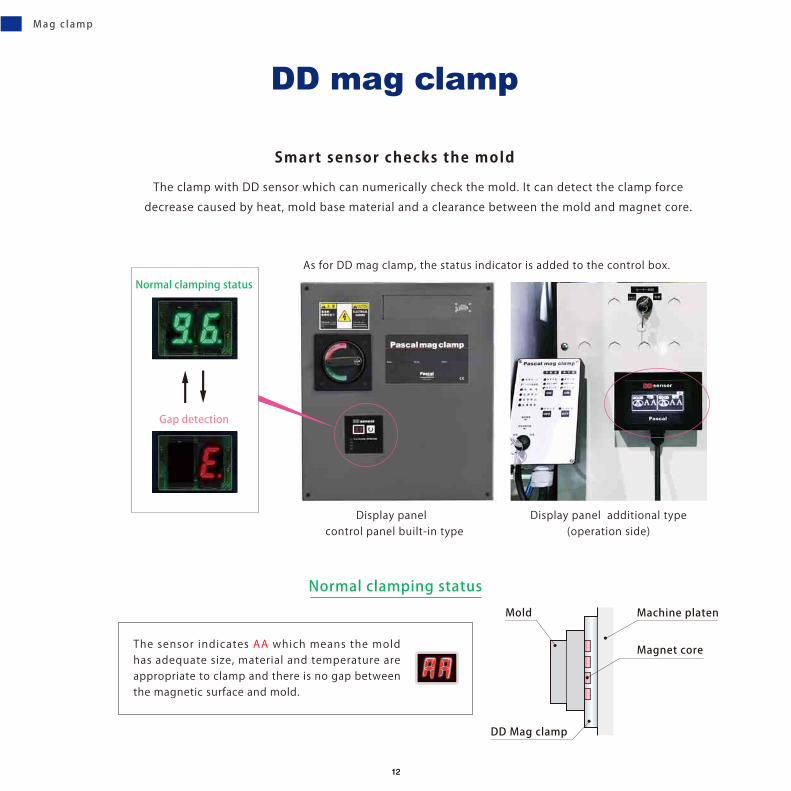
An economical control system that can operate the clamp with limited function(built in simplified safety interlocks)
Operation panel ELC-B/Smart clamp
Conventional way of operation and control Operation panel ELC-B
Control box(to be installed in the machine
control panel)
Operation panel
model
ESTE-A
Operation panel
model
ELC-B
Control box
model
ECTE
It is applicable to the customers who
・ want to increase the number of clamp system but to reduce the initial cost.・ want to automate only the clamping and unclamping the mold.
● Not applicable to automatic slidable clamp.
Hydraulic clamp
TYA TYC-Z/R TYA-M TME TKB
○ × ○ ○ ○
Air clamp
TLC TLC-Z/R TLA-M TLA
○ × ○ ○
Opera t ion pane l ELC-B
3030

Mold changer
Safety door
For small, medium and large-sized IMM
Centering cylinder MHP
Clamp
Clamp
Stopper block MVA
Mold roller MCR
Roller blockMHR
Hyd. Air
Hyd. Air
IMM Hor izonta l loading
3131

helps automatic leveling of the mold after centering with a locate ring
3,500kN(350ton)IMM Vertical loading Die leveler & Locate ring & Mag clamp
Die leveler
Air cylinder
Pusher
Guide
Die leveler base
400kg
MDH04
800
MDH08
1200
MDH12Model
Mold weight
Locate ring&Die leveler
Die leveler new
Die leve ler
3232

2,800kN(280ton)Two-color IMM Application example 2,800kN(280ton)Two-color IMM Application example
When installing the mold
Down(Retracted) Up (Mold is leveled)
Mag clamp
Guide
Pusher
Mold
Mag clamp
GuideGuide Guide
Die levelerMDH04 ,08,12
Die levelerMDH04 ,08,12
Pusher
Air cylinder Air cylinder
Mold* Sketch for just an example
X
Y
Locate ringLocate ring
X
Y
1.2 ton
Mold weightMax.
Die leve ler
3333

A new proposal to enable the mold setting to be easy.
Slide block (vertical guide) and die setter (leveling guide) allow the mold centering
quick and simple.
2,300kN IMM Quick locating system practical example
Slide block (vertical guide)
Die setter(Leveling guide)
Quick locating system new
Quick locat ing system
3434

Movableplaten
Mold
Mold
Mold
Locate ring
Fixed platen
Mag clampSlide block(Vertical guide)
Fixed platen
Fixed platen
Insert a locate ring
Die setter (Leveling guide)
Die setter (Leveling guide)
Die setter (Leveling guide)
Clearance
Clearance
Movableplaten
Mold setting procedure
Push the mold against the slide block.
Y-axis is fixed.
Mold loading in
Slide the platen back to make a clearance
Place the mold on the die setter
X-axis is fixed
Slide the platen forward to get the locate ring in the hole
Mold setting is over
Quick locat ing system
3535

Die setter
3,500kN(350ton)IMM Vertical loading Die setter & Mag clamp
1000kg
MDL01
3000
MDL03
4000
MDL04
6000
MDL06
10000
MDL10
15000
MDL15Model
Mold weight
Introducing a Die setter, the horizontal and vertical positioning can be determined surely and easily
by placing a mold on a Die setter and it can reduce mold set-up time and improve the productivity .
New proposal in place of conventional locate ring
Die setter
Die set ter
3636

1,800kN(180ton)IMM Vertical loading Die setter & Hydraulic clamp, slidable type TYA040
3,500kN(350ton)IMM Horizontal loading Die setting roller & Mag clamp
Die set ter
3737

Die set blockThe lower end position of die set block
Leveling block(Spacer for height adjustment)
Guide
Centering pin
Die set base
Up Down
Air cylinder
Leveling blockPositioning by putting leveling block between a die set block and die set base.
Die set ter
3838

Y
ZX
Z
Y
X
Die setter Die setter
Locate ring
Die setting with die setter
Hard to fit the ring into the nozzle hole
By placing a mold on a die setter,mold is easily positioned.
Mold center(X ,Y) is not stable.
Mold centering(X,Y)is quickly secured.
Die setting with locate ring
It is not easy to check from back side of the platen if thering fits in the hole by slinging the mold by overhead crane, in addition, there is a risk of damage of surface of platenor mold itself.( )
Die set ter
3939

Octagonal locate ring(Base)
Mold side Fixed platen side
Octagonal locate block(Locate ring cylindrical)
Mold positioning for insert / hoop molding
Octagonal locate ring
For improvement of mold set-up time.
The use of octagonal locate ring (octagonal taper cone) provides easy positioning,
eliminating need for retraining of robot.
Octagonal locate r ing
4040

A
A
B
BA-A B-B
Mold
ø70ø100ø120
Fixed platen
Octagonal locate block MCL 70PMCL 100PMCL 120P
MCL 70SMCL 100SMCL 120S
Octagonal locate ring
Mold weight
High rigidity can be obtainedby receiving mold weighton multiple faces.
Restrained 8-faces can provideeasy centering.Taper allows easy mold setting.
1,800kN(180ton) IMM Vertical loadingOctagonal locate ring & Mag clamp
500kN(50ton) Vertical IMMOctagonal locate ring(positioning for upper mold)&Rollers
Octagonal locate r ing
4141

5,500kN(550ton) IMM
Changing ejector rod
3min13sec to 30sec
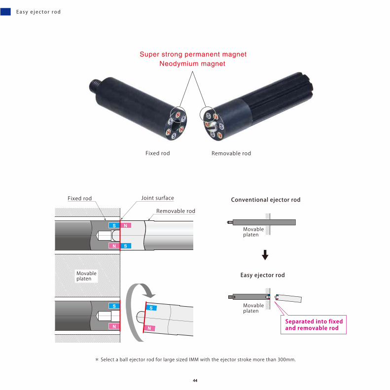
Pascal Easy ejector rod makes an ejector rod changing dramatically easier
Easy ejector rod
It is a newly designed ejector rod with strong magnets on the joint surface
of the fixed/removable rods, which plugs in/out by one-touch operation.
30,00030,000pieces
have beensold
Step1
improvement of
Moldchange
Easy e jector rod
4242

1min08secto
6sec
1,000kN IMM
5,500kN IMM
5min30secto
20sec
Easy e jector rod
4343
S
N
S
N
S
N
N
S
* Select a ball ejector rod for large sized IMM with the ejector stroke more than 300mm.
Fixed rod Joint surface
Removable rod
Movableplaten
Conventional ejector rod
Easy ejector rod
Movableplaten
Movableplaten
Fixed rod Removable rod
Neodymium magnetSuper strong permanent magnet
Separated into fixedand removable rod
Easy e jector rod
4444
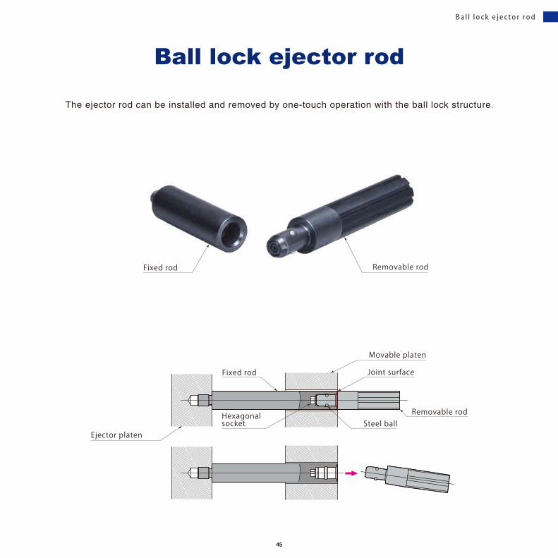
Fixed rod Removable rod
The ejector rod can be installed and removed by one-touch operation with the ball lock structure .
Ball lock ejector rod
Joint surface
Removable rod
Movable platen
Steel ball
Fixed rod
Ejector platen
Hexagonalsocket
Bal l lock e jector rod
4545
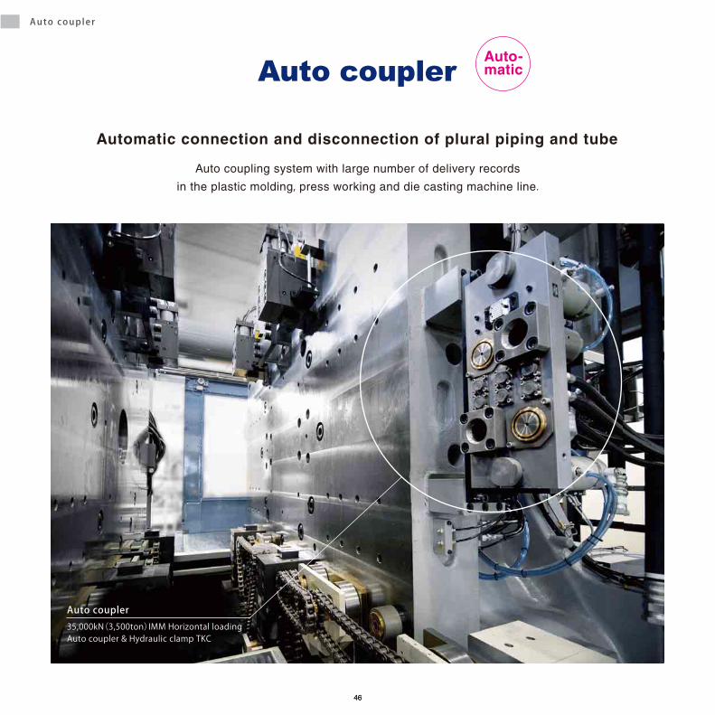
35,000kN(3,500ton)IMM Horizontal loading Auto coupler & Hydraulic clamp TKC
Auto coupler
Automatic connection and disconnection of plural piping and tube
Auto coupler
Auto coupling system with large number of delivery records
in the plastic molding, press working and die casting machine line.
Auto-matic
Auto coupler
4646

Coupler(Water, Air) 1 1/2” × 2 ports
Lock guide socket(Guide with locking device)
Mold detectionproximity switch
Lock guide pin
Coupler(Water, Air) 1/2” × 2 ports
Coupler(Water, Air) 3/8” × 20 ports
Air cylinderSelf-alignmentmechanism(±5mm) Electric connector
Hydraulic , Water , Air
3/8”, 1/2”, 3/4”, 1”, 1 1/4”, 1 1/2”, 2”
Coupler , Electric connector , Lock guide , Mold detection proximity switch(Special)
Connection port
Fluid
Module
Auto coupler
4747

4,500kN(450ton) IMM Horizontal loading Mag clamp & Auto coupler
Auto coupler
4848

4,500kN(450ton)IMM Horizontal loading Auto coupler & Mag clamp
35,000kN(3,500ton) IMM Horizontal loading Auto coupler & Air clamp
Auto coupler
4949

1/4”Connection port
PAT.
Machine sideC&C coupler
2,500kN(250ton)Two-color IMM Horizontal loading Fixed side Mag clamp & C&C coupler
Hydraulic , Water , Air
Max . 1MPa
Coupler , Electric connector
FluidPressure
Module
It is a simple mechanism of coupler which maintains connectionby the mold clamp.
C&C coupler Auto-matic
C&C coupler
5050

Air clamp
Centering block
Mold side C&C couplerunit
Machine side C&C couplerunit
Mold stopper
Mold
Air clamp
Mold side C&C couplerunit
Machine side C&C couplerunit
Positioning cylinder
Mold
Release Coupling
Release Coupling
No driven cylinderand compact size
No driven cylinderand compact size
Vertical loading
Horizontal loading
C&C coupler
5151

Multiple couplers are connectable easily and securely by pushing the gripper slightly. It prevents misplace of couplers and can shorten the coupling time.
Multi coupler
18,000kN(1800ton) IMM Multi coupler Open model
Manualnew
Mult i coupler
5252

Gripper
IndicatorMachine side (Socket) coupler
Incorrect connectingprevention pin
Lock guideMold side (Plug) coupler
Lock ring
Gripper
Machine side (Socket) couplerMold side (Plug) coupler
Incorrect connectingprevention hole
Incorrect connectingprevention hole
Incorrect connectingprevention pin
The locking completion can be recognizedat a glance with this indicator.
Coupling Release
Lock ring
Pull slightly
Mult i coupler
Insert the couplers(Female) along the guide Push the gripper slightly and the lockinghas been completed.
Hold the gripper and pull the lock ring slightly and the couplers disconnect.
Locking operation
Release operation
5353

Check valve model
4、 6、 8Number of port
Connection port
Hydraulic , Water , Air
Max . 0 .8MPa
Fluid
Pressure
A manual coupler which check valve is operable by a pilot pressure .
Rc1/4
Mold (socket) coupler Machine (plug) side
Check valve
Coupler machine (plug) side
Lock guide pin
Coupler mold(socket)side
Lock guide socket
Incorrect connectingprevention hole
Gripper
Incorrect connectingprevention pin
8,500kN(850ton) IMM
Mult i coupler
5454

Open (Check valve-less) model
Mold side (plug) coupler Machine (socket) side Mold (plug) side Machine (socket) side
An open type of coupler has no check valve , and the pressure loss is small.
Malfunction caused by foreign substances besing caught into the coupler does not occur.
6、 8、 12Number of port
Connection port
Hydraulic , Water , Air
Max . 0 .8MPa
Fluid
Pressure
Rc1/4 Rc3/8
Incorrect connectingprevention hole
Incorrect connectingprevention hole
Incorrect connectingprevention pin
Incorrect connectingprevention pin
Lock guide pin Lock guide pin
Open type coupler (plug side)
Open type coupler (plug side)
Open type coupler (socketside)
Open type coupler (socket side)
Lock guide socket Lock guide socket
Gripper Gripper
Single row typeDouble row type
Mold side 6,000kN(600ton) IMM
Mult i coupler
5555

30,000kN(3,000ton) IMM Horizontal loading Mold changer : Powered, Drive rollers type 2 molds & Mag clamp
It is an automatic mold changer which can shorten the mold changing time considerably,
comparing with the conventional forklift or overhead crane.
Mold changer
Mold changer
5656
Changer Changer Rail
Roller table
Pusher stand
Drive rollers
Changer
Changer
Roller table
Pusher(Incorporated in mold changer)
Drive rollers
Changer
Roller table Mold rack
Mold rack
Mold rack
Rail
RailRail
Changer
Changer
Fixed roller tableRailStand-by position
Rail
Drive rollers Drive rollers
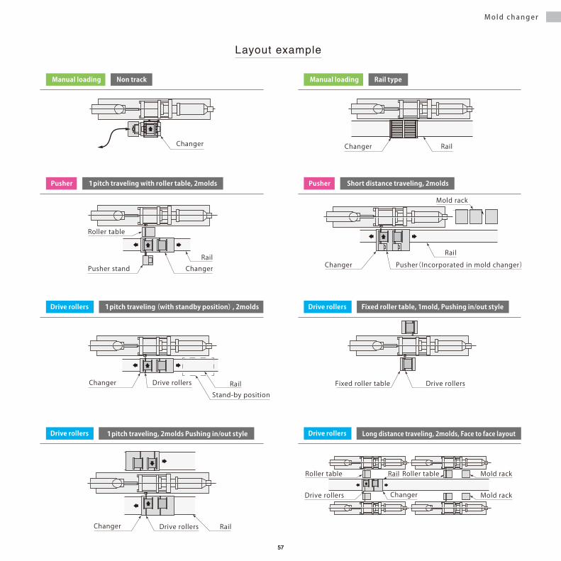
Layout example
Manual loading Non track Manual loading Rail type
1pitch traveling with roller table, 2moldsPusher Short distance traveling, 2moldsPusher
1pitch traveling(with standby position), 2moldsDrive rollers Fixed roller table, 1mold, Pushing in/out styleDrive rollers
1pitch traveling, 2molds Pushing in/out styleDrive rollers Long distance traveling, 2molds, Face to face layoutDrive rollers
Mold changer
5757

Lever(Stopper)
Lever(Positioning)
Manual loading, Non track, Non elevated table type modelQMF
Manual loading, Non track, Table elevation type modelQMA
Mold changer
Model QMF1 QMF2Clamping force of IMM 400 ~ 1000 kN (40 ~ 100 tonf) 400 ~ 600 kN (40 ~ 60 tonf)
Max. mold weight 600 kg 300 kg
Number of load 1mold 2molds
Model QMA1Clamping force of IMM 400 ~ 1000 kN (40 ~ 100 tonf)
Max. mold weight 300 kg 600 kg
Number of load 1mold
5858

Battery-powered, Non track, Table elevation type modelQMB
Manual loading, Rail type modelQME
Mold changer
Model QMB1Clamping force of IMM 400 ~ 4500 kN (40 ~ 450 tonf)
Max. mold weight kg 800 1500 2500
Number of load 1mold
Model QME
Clamping force of IMM 500 kN(50 tonf)
800 kN(80 tonf)
1000 kN(100 tonf)
1300 kN(130 tonf)
1500 kN(150 tonf)
2000 kN(200 tonf)
2500 kN(250 tonf)
Max. mold weight kg 300 400 400 600 800 1000 2000
Number of load 2molds
5959

500kN (50ton) IMM Horizontal loading Mold changer:Manual loading, Non track, Table elevation type
2,500kN (250ton) Two-color IMM Horizontal loading Mold changer:Powered, Drive rollers type
Mold changer
6060

4,500kN (450ton) IMM Horizontal loading Mold changer:Powered, Drive rollers type
2,500kN (250ton) Two-color IMM Horizontal loading Mold changer:Manual loading, Rail type
Mold changer
6161

High rigidity roller gear
Electric motorLarge sized sprocket
Roller gear driven (electric motor) type
1, 3 , 5, 10, 15, 20, 30, 50Max. rotation weight (ton)
Powered
model SMRRoller gear driven type
Mold rotator
Model SMR rotates the table with high rigidity roller gear and large sized sprocket, which enables
excellent in durability and safety by introducing roller gear driven type(PAT.).
Mold rotator
6262

Hydraulic cylinder driven type
10, 15, 20, 30
Flat type model SMF
Model SMF is embrddable in the floor.
The table is flattened also rigid enough to be passed over by a forklift or a truck .
Mold rotator
Roller gear driven (electric motor) type
1, 3 , 5Max. rotation weight (ton)
Powered
Picture of 20ton mold type
Hyd.
Mold rotator
6363

Die weight 8 ton (4 ton per each side)
Hydraulic piping to core cylinder
Stage for rotationStage for separation
Die 4ton Die 4ton
Die rotator with separation
Mold maintenance work can be performed outside the machine without lowering machine operation rate.
Die rotator
6464

Die weight 15 ton (7.5 ton per each side)
Mold separator with magnetic platen
Magnetic clamp(Stage for movable)
Magnetic clamp(Stage for fixed)
Mold separator
6565

kg5 10 20 40 60 100 150 200 kg5 10 20 40 60 100 150 200Payload
For plastic molding machine For the welding line
Robot tool changer
Robot too l changer
6666

Excellent durability
N2 gas spring
For quick cam or ejector plate return.
Gas spr ings
6767

JAPAN
DOMESTIC LOCATIONS
Yamagata
Kumagaya
AtsugiNagoya
Head office(Itami, Hyogo)Oita
Hiroshima
Sales office
Plant
Head office / R & D center
Oita
Yamagata
Itami, Hyogo
Oita plant Yamagata plant
Kumagaya, Saitama
Atsugi, Kanagawa
Nagoya, Aichi
Osaka, Hyogo
Yamagata
Hiroshima
68

ASIA AMERICA
EUROPE
Dalian plant
Dalian[China]
Shanghai[China]
Deltamas[Indonesia]
Kuala Lumpur[Malaysia]
Mumbai[India]
Melbourne[Australia]
Bangkok[Thailand]
Changwon[Korea]
Chicago[U.S.A.]
Queretaro, Leon[Mexico]
Sao Paulo[Brazil]
Liaison officeSales office
Stuttgart[Germany] Paris[France]
Torino[Italy] Barcelona[Spain]
SubsidiaryPlantAgent
GLOBAL NETWORK
Torino(Italy)
Barcelona(Spain)
Dalian
Chongqing Shanghai
Changwon(Korea)
Guangzhou
Wuhan
Changchun
Stuttgart(Germany)
Paris(France)
Tianjin
Melbourne(Australia)
Bangkok(Thailand)
Kuala Lumpur(Malaysia)
Deltamas(Indonesia)
Taichung(Taiwan)Mumbai
(India)
Chicago(U.S.A.)
Queretaro,León(Mexico)
Sao Paulo(Brazil)
Changchun[China]
Tianjin[China]
Wuhan[China]
Chongqing[China]
Guangzhou[China]
Taichung[Taiwan]
Bursa(Turkey)
Bursa[Turkey]
69

For die and mold Pres s mach ine :Body,Roo f ,Doo re tc . . .Mo ld ing mach ine :Bumper,In s t rument pane le tc . . .
For sheetmetal s tamping For p last ic molding
Mold die c lamping system
Mag c lamp N2 gas spr ingsAuto couplerTrave l ing c lamp Stamping d ie c lamp
Pasca l p roduc ts a re suppor t i ng
C o n n e c t o r I n s t r u m e n t p a n e l
B o d y
B u m p e r W h e e lD o o r
70

For die cast machine For metal cut t ing machine l ine
C-plate mag c lampDie-c lampingsystem
Work c lamp Pal let c lamp Index tab le N2 gas ba lancer
au tomot i ve p roduc t ion l i nes i n the wor ld .
E n g i n e
T r a n s m i s s i o n A x l e
71

PA-263E-19 2019.11 Specifications are subject to change without prior notice.
CERTIFICATE OF APPROVAL ISO9001