Embed Size (px)
Citation preview
Transactions of the Canadian Society for Mechanical Engineering, Vol. 37, No. 2, 2013 259
STRUCTURAL SYNTHESIS OF ANCIENT CHINESE ORIGINAL CROSSBOW
Kuo-Hung Hsiao
Collections and Research Division, National Science and Technology Museum, Kaohsiung, Taiwan
E-mail: [email protected]
Received January 2013, Accepted March 2013
No. 13-CSME-03, E.I.C. Accession 3461
ABSTRACT
The original crossbow was one of the most important weapons in ancient China. Since crossbows have
diversified types and were widely used in ancient China after the Spring and Autumn Period (770-476
BC), the original crossbow should have many designs in different eras and regions. The aim of this work
is to synthesize mechanism structures of the original crossbow. Based on the analyses of crossbows, the
structural characteristics and design constraints of this device are concluded. Then, according to the
concepts of generalization and specialization subject to the concluded design constraints, twelve feasible
structures of mechanism that meet the technological standards of the subject’s time period are
reconstructed.
Keywords: crossbow; structure of mechanism; reconstruction design; history of machinery.
SYNTHÈSE DES STRUCTURES D’UNE ANCIENNE ARBALÈTE CHINOISE
RÉSUMÉ
L’arbalète originale était l’une des plus importantes armes de guerre dans la Chine antique. Étant donné
qu’il y a plusieurs types d’arbalètes, et qu’elles étaient largement utilisées dans la Chine antique après la
période Printemps/Automne (770-476 avant notre ère), l’arbalète originale devait être différente selon les
époques et les régions. Le but de ce travail est de faire une synthèse des structures mécaniques de
l’arbalète originale. En se basant sur l’analyse des arbalètes, les caractéristiques de structure et de
contraintes de conception sont établies. Ensuite, selon les concepts généraux et spécifiques, en tenant
compte des contraintes, douze structures de mécanismes possibles, qui rencontrent les standards
technologiques de l’époque, ont été construites.
Mots-clés : arbalète; structure mécanique; concept de reconstruction; histoire des machines.

260 Transactions of the Canadian Society for Mechanical Engineering, Vol. 37, No. 2, 2013
NOMENCLATURE
KBB Bamboo
KCB Bow
KF Frame
KI Input link
KL Connecting link
KPL Percussion link
KT Thread/bowstring
J Number of joints
JA Cam joint Pxyz
RxyzJ An unconstrained pairing element
JBB Bamboo joint
JP Prismatic joint
J Py
Joint translates along y-axis
J Pyz
Joint translates along y and z axes
J Pxyz
Joint translates along x, y and z axes
JR Revolute joint
JRx Joint rotates about x-axis
JRxyz Joint rotates about x, y and z axes
JRz Joint rotates about z-axis Pz
RxJ Joint translates along z-axis and rotates about x-axis
Px
RyzJ Joint translates along x-axis and rotates about y and z axes
JT Thread joint
N Number of links
1. INTRODUCTION
According to the literatures and the excavations, ancient Chinese crossbows have three types
including the original crossbow, Chu State repeating crossbow and Zhuge repeating crossbow. An
original crossbow is a weapon bow mounted on a stock with a trigger mechanism for holding the drawn
bowstring as shown in Fig. 1 [1]. It was the standard military issue of the ancient Chinese arsenal. The
earliest one was found in the tomb at Qufu, Shangdong Province and dated to the 6th century BC [2]. The
trigger mechanism was designed in such a way that it was able to store a large amount of energy within
the bow when drawn, but was easily fired with little recoil when the input link was pulled. It also allowed
the shooter to aim the target for precision shooting. The shooting process of crossbow includes three
steps: drawing the bowstring, placing the bolt and shooting the bolt. A repeating crossbow is a crossbow
where the separate actions of three steps can be accomplished with a simple one-handed movement while
keeping the crossbow stationary. This allows a higher rate of fire than an original crossbow. Based on the
archeological finds, the repeating crossbow first appeared around 400 BC in the tomb in Hubei Province
as shown in Fig. 2 [3]. The magazine fixes on the top of the stock and contains twenty bolts, and the
device is worked by moving the input link forward and backward. Two bolts can be shot at once in the
reciprocating motion of the input link. Since the tomb belonged to Chu State during the War States
Period (722-481 BC), the device was named Chu State repeating crossbow. The Records of the Three
Kingdoms mentions another type of repeating crossbow named “Zhuge repeating crossbow” and
describes the strategist Zhuge Liang (181-234 AD) of the Three Kingdoms Period (220-280 AD) as the
inventor [4]. Figure 3 is a Zhuge repeating crossbow in the book of Treatise on Armament in the Ming

Transactions of the Canadian Society for Mechanical Engineering, Vol. 37, No. 2, 2013 261
Dynasty (1368-1644 AD) [1]. The magazine contains a number of bolts and functions as a percussion
link. The function of the percussion link with the magazine is to draw and release the bowstring to shoot
the bolt. When the device is worked by moving the input link, one or several bolts can be shot at once in
the oscillating motion of the input link. Since the types of crossbows were diversified and widely used in
ancient China, the structures of each crossbow should have many designs in different eras and regions. In
order to realize the development of ancient Chinese crossbows, it is necessary to study further for
accessing and understanding the real ancient technology.
Fig. 1. An original crossbow [1]
(a) Actual excavation (b) Structure
Fig. 2. Chu State repeating crossbow [3]
Fig. 3. Zhuge repeating crossbow [1]
K C B (2)
K F (1)
K P L (5)
K T (3)
K I (4)
K F (1)
K C B (2)
K F (1)
K P L (5)
K T (3)
K I (4)
K F (1)

262 Transactions of the Canadian Society for Mechanical Engineering, Vol. 37, No. 2, 2013
The purpose of this work is to synthesize all feasible structures of the original crossbow. In what
follows, the mechanism structures of ancient Chinese crossbows are analyzed first. And, the
representation of joints of ancient mechanisms is presented. Then, an approach for synthesizing the
structures of ancient mechanisms with diversified types is introduced. Finally, the structural synthesis of
the original crossbow is provided.
2. STRUCTURAL ANALYSIS OF ANCIENT CHINESE CROSSBOW A mechanism which encounters a certain changes in its topological structure during operation is
called a reconfigurable mechanism. The topological structures of a crossbow are different during
shooting process. Therefore, ancient Chinese crossbow is a reconfigurable mechanism. It can be
normally treated as a kinematic chain with variable architectures depending upon the inherent topology
variability. Such chain is namely a variable kinematic chain or variable chain in short. Either from the
aspect of overall structure or the interior connectivity, a mechanism will topologically be a variable chain
if the arrangement of this chain is changeable.
The original crossbow and Chu State repeating crossbow generally consist of six members including
the frame KF(1), the bow KCB(2), the bowstring KT(3), the input link KI(4), the percussion link KPL(5) and
the connecting link KL(6) as shown in Figs. 1 and 2. The structure of Zhuge repeating crossbow is
simplified and the number of members is five without the connecting link as shown in Fig. 3. According
to topology variability, the operations of ancient Chinese crossbows can be divided into the following
four stages:
1. The undrawn stage
The purpose of this stage is to draw the bowstring. The bow and the bowstring are temporarily
immovable, Figs. 4(a1), (b1) and (c1). Then, the input link, the percussion link and the connecting link are
adjusted such that the bowstring can be properly drawn. When the bowstring is drawn instantly, the
operation enters the second stage.
2. The drawing stage
Since the bowstring is forced to complete the drawing by the shooter’s hands in the original crossbow,
the parts of trigger mechanism can be treated as to be incorporated with the frame, Fig. 4(a2). However,
the bowstring is automatically hooked through the operation in the repeating crossbow, Figs. 4(b2) and
(c2). When the bowstring completed the drawing, the operation enters into the next stage.
3. The drawn stage
When the shooter had drawn the bowstring and placed the bolt, the shooter can aim the target for
precision shooting in the original crossbow, Fig. 4(a3). However, the bolt falls from the magazine by
gravity in the repeating crossbow. When the bowstring is drawn in the maximum position, the percussion
link is adjacent to the frame in Chu State repeating crossbow, Fig. 4(b3) and the bowstring is adjacent to
the frame directly in Zhuge repeating crossbow, Fig. 4(c3). When the input link is driven and the
bowstring is released, the operation enters into the next stage.
4. The shooting stage
Through the elasticity of the bow and the bowstring, the bolt starts to be forced at this stage. Until the
bolt is shot away, the bow and the bowstring return to the original position and the function cycle will be
periodically continued. In addition, the input link, the percussion link and the connecting link can be
treated as to be incorporated with the frame, Figs. 4(a4), (b4) and (c4).
3. REPRESENTATION OF JOINTS Through the study of ancient mechanisms no matter in drawings or excavations, the joints can be
classified into three types including joints that are easy to identify such as gear joints and wrapping joints,
joints that are uncertain, and joints that are certain but are rare in modern kinematics of mechanisms.

Transactions of the Canadian Society for Mechanical Engineering, Vol. 37, No. 2, 2013 263
(a1) (a2) (a3) (a4)
(a) Original crossbow
(b1) (b2) (b3) (b4)
(b) Chu State repeating crossbow
(c1) (c2) (c3) (c4)
(c) Zhuge repeating crossbow
Fig. 4. The variable kinematic chains of ancient Chinese crossbows
Since some special joints in ancient mechanisms can not be represented by modern schematic
representations, a novel representation for such joints in ancient mechanisms is introduced here [5, 6].
The number of degrees of freedom is the number of independent parameters needed to specify the
relative positions of the pairing elements of a joint. An unconstrained pairing element has six degrees of
freedom including three translational and three rotational degrees of freedom. And, a joint is represented
as xyz
xyz
P
RJ in which the superscript
xyzP denotes that it can translate as a prismatic joint (JP) along x, y and z
axes; and the subscriptxyzR denotes that it can rotate as a revolute joint (JR) about x, y and z axes. When a
pairing element connects to another pairing element and forms a joint, a constraint is imposed and the
motion of the original member is reduced by one or more degrees of freedom. Hence, a joint has a
maximum of five degrees of freedom and a minimum of one degree of freedom. For example, jointxRJ
represents that a pairing element of a joint can rotate about x-axis with respect to the other pairing
element. Joint zpJ represents that a pairing element of a joint can translate along z-axis with respect to the
other pairing element. And, joint x
yz
P
RJ represents that a pairing element of a joint not only translates along
x-axis and also rotates about y and z axes with respect to the other pairing element.
Figure 5(a) shows a two-member mechanism with a joint from the book of Chinese Technology in the
Seventeenth Century [7]. Since the drawing is not clear, link KL is adjacent to frame KF with an uncertain
joint. Considering the type and the direction of motion of the link, the joint has two possible types: the
link rotates about z-axis only, denoted asRzJ ; and, the link rotates not only about z-axis but also translates
along x-axis, denoted as Px
RzJ . The x and y axes are defined as the horizontal and vertical directions in the
drawing, respectively. The z-axis is determined by the right-hand rule.

264 Transactions of the Canadian Society for Mechanical Engineering, Vol. 37, No. 2, 2013
(a) (b)
Fig. 5. Special joints in ancient mechanisms [7]
Thread and bamboo often appear as members in ancient mechanisms especially in textile and
agricultural devices. Figure 5(b) shows that bamboo KBB is adjacent to frame KF and thread KT
from the
book of Chinese Technology in the Seventeenth Century [7]. The bamboo is firmly fixed to the frame
and the thread ties the bamboo directly. The bamboo possesses elasticity and can go back to the original
position after using. The motion of the bamboo can be regarded as a link adjacent to the frame with a
revolute joint. The joint incident to the bamboo and the frame is defined as a bamboo joint, denoted as
JBB. Using a thread tying a member to form a joint is rare in modern mechanisms but popular in ancient
mechanisms. The joint incident to the thread and a member is defined as a thread joint, denoted as JT.
4. DESIGN APPROACH Figure 6 shows the process for synthesizing all feasible structures of ancient mechanisms with
diversified types [5, 8-11]. Each step of the process is explained as follows:
Step 1. Analyses of the structures of mechanisms
By analyzing the structure of a target mechanism, its structural characteristics are concluded including
the possible number of members and incidences among members and joints of the device. Since the
development of the similar mechanisms should influence each other, the structures of different devices
with the same function are usually alike. Therefore, the number of members and the structures of joints
of the relevant mechanisms can be considered. For example, ancient Chinese crossbows have three types.
One’s structural characteristics may be the other one’s design constraints.
Step 2. Generalized chains
The second step is to obtain or identify the atlas of generalized chains with the same numbers of
members and joints subject to concluded structural characteristics based on the concept of number
synthesis [12-13]. Generalization is to transform the mechanism, that involves various types of members
and joints, into a generalized chain with only generalized links and joints. A generalized link is a link
with generalized joints; it can be a binary link, ternary link, quaternary link, …etc. A generalized joint is
a joint in general; it can be a revolute joint, prismatic joint, spherical joint, or others. When several
members are connected by joints, they are said to form a chain. Graphically, a joint is symbolized by a
small circle, and a member with i incident joints is symbolized by an i-side shaded polygon with small
circles as vertices. Some of the important atlases of generalized chains have already been built in
references [12-13].

Transactions of the Canadian Society for Mechanical Engineering, Vol. 37, No. 2, 2013 265
Fig. 6. Process for structural synthesis of ancient mechanisms with diversified types
Step 3. Specialized chains
Specialization is to assign specific types of members and joints in the available atlas of generalized
chains, subject to required design constraints [12-13]. Design constraints are defined based on the
concluded structural characteristics. And, a generalized chain after specialization is a specialized chain.
Based on the process of specialization, all possible specialized chains can be identified after assigning the
types of members and joints subject to the concluded design constraints for each generalized chain
obtained in step 2.
Step 4. Specialized chains with particular identities
In order to represent the structure of mechanism, a right-hand rectangular Cartesian coordinate system
is defined to describe each motion axis of the joints. By studying the target device, the function of the
device is determined. In view of the device function, these uncertain joints can be represented by
different types of joints to achieve the equivalent function. Considering the types and the motion
directions of the uncertain joints, all possible types of the uncertain joints are generated. By assigning the
possible types of the uncertain joints to the specialized chains obtained in step 3, specialized chains with
particular identities are obtained.
Step 5. Feasible designs
According to the motion and function requirements of the device, all feasible designs that meet the
technological standards of the subject’s time period can be obtained from the specialized chains with
particular identities.
5. STRUCTURAL SYNTHESIS According to the literature and the actual excavation, the original crossbow comprises six members
including the frame, a bow, a bowstring, an input link, a percussion link and a connecting link. And, it
has eight joints including one bamboo joint (JBB), two threat joints (JT), two cam joints (JA) and three
revolute joints (JRz). Since the original crossbow was popular and widely used in different eras and
regions, the structures of the original crossbow should have different designs. Furthermore, through the
integrating with geometry and kinematics, the trigger mechanism without the connecting link still has the

266 Transactions of the Canadian Society for Mechanical Engineering, Vol. 37, No. 2, 2013
function of pulling bowstring by the percussion link, like Zhuge repeating crossbow with five-member
and six-joint. Therefore, the number of members of the original crossbow should be five or six. All
feasible structures of the original crossbow are synthesized through the following steps to illustrate the
introduced approach shown in Fig. 6:
Step 1. The structural characteristics of the device are:
1. It is a cam mechanism with five-member and six-joint or six-member and eight-joint.
2. The frame (KF) is a multiple link and adjacent to a pair of binary links.
3. The bow (KCB) is a binary link and adjacent to the frame (KF) with a bamboo joint (JBB).
4. The bowstring (KT) is a binary link and adjacent to the bow (KCB) with a thread joint (JT).
5. The input link (KI) is adjacent to the frame (KF) with a revolute joint (JRz) and is not adjacent to the
bowstring (KT).
6. The percussion link (KPL) is adjacent to the frame (KF) with an uncertain joint.
7. The connecting link (KL) is adjacent to the percussion link (KPL) and the input link (KI) with
uncertain joints.
Step 2. Since this is a device with five-member and six-joint or six-member and eight-joint, the
corresponding generalized chains are shown in Fig. 7, in which N is the number of links and J is the
number of joints.
(a1) (a2)
(a) N=5, J=6
(b1) (b2) (b3)
(b4) (b5) (b6)
(b7) (b8) (b9)
(b) N=6, J=8
Fig. 7. Atlas of some generalized chains with five and six members

Transactions of the Canadian Society for Mechanical Engineering, Vol. 37, No. 2, 2013 267
Step 3. There must be a pair of binary links as a bow and a bowstring. And, the pair of binary links
must be adjacent to a multiple link as the frame. Therefore, only four generalized chains shown in Figs.
7(a2), (b3), (b4) and (b6) are qualified for the process of specialization. And, all possible specialized
chains are identified as follows:
Frame --- link KF
Since there must be a multiple link as the frame (KF) and a pair of binary links is adjacent to the
frame, the frame is identified as follows:
1. For the generalized chain shown in Fig. 7(a2), the assignment of the frame (KF) generates one non-
isomorphic result, Fig. 8(a1).
2. For the generalized chain shown in Fig. 7(b3), the assignment of the frame (KF) generates two results,
Figs. 8(a2) and (a3).
3. For the generalized chain shown in Fig. 7(b4), the assignment of the frame (KF) generates one non-
isomorphic result, Fig. 8(a4).
4. For the generalized chain shown in Fig. 7(b6), the assignment of the frame (KF) generates one non-
isomorphic result, Fig. 8(a5).
Therefore, five specialized chains with identified frame (KF) are available as shown in Figs. 8(a1)-(a5).
Bow and bowstring --- link KCB and link KT
Since there must be a pair of binary links as the bow (KCB) and bowstring (KT), and the bow is
adjacent to the frame and the bowstring with a bamboo joint (JBB) and a thread joint (JT), the bow and the
bowstring are identified as follows:
1. For the case shown in Fig. 8(a1), the assignment of the bow (KCB) and the bowstring (KT) generates one
result, Fig. 8(b1).
2. For the case shown in Fig. 8(a2), the assignment of the bow (KCB) and the bowstring (KT) generates one
result, Fig. 8(b2).
3. For the case shown in Fig. 8(a3), the assignment of the bow (KCB) and the bowstring (KT) generates one
result, Fig. 8(b3).
4. For the case shown in Fig. 8(a4), the assignment of the bow (KCB) and the bowstring (KT) generates one
result, Fig. 8(b4).
5. For the case shown in Fig. 8(a5), the assignment of the bow (KCB) and the bowstring (KT) generates one
result, Fig. 8(b5).
Therefore, five specialized chains with identified frame (KF), bow (KCB) and bowstring (KT) are
available as shown in Figs. 8(b1)-(b5).
Input link --- link KI
Since there must be an input link (KI) that is adjacent to the frame (KF) with a revolute joint (JRz) and
not adjacent to the bowstring (KT), the input link is identified as follows:
1. For the case shown in Fig. 8(b1), the assignment of the input link (KI) generates one result, Fig. 8(c1).
2. For the case shown in Fig. 8(b2), the assignment of the input link (KI) generates one result, Fig. 8(c2).
3. For the case shown in Fig. 8(b3), the assignment of the input link (KI) generates two results, Figs. 8 (c3)
and (c4).
4. For the case shown in Fig. 8(b4), the assignment of the input link (KI) generates one non-isomorphic
result, Fig. 8(c5).
5. For the case shown in Fig. 8(b5), the assignment of the input link (KI) generates one non-isomorphic
result, Fig. 8(c6).
Therefore, six specialized chains with identified frame (KF), bow (KCB), bowstring (KT) and input link
(KI) are available as shown in Figs. 8(c1)-(c6).
Percussion link and connecting link --- link KPL and link KL

268 Transactions of the Canadian Society for Mechanical Engineering, Vol. 37, No. 2, 2013
Since the percussion link (KPL) must be adjacent to the frame (KF) and the input link (KI) with
uncertain joints and the remaining one is the connecting link, the percussion link and the connecting link
are identified as follows:
1. For the case shown in Fig. 8(c1), the assignment of the percussion link (KPL) generates one result, Fig.
8(d1).
2. For the case shown in Fig. 8(c2), the assignment of the percussion link (KPL) and the connecting link
(KL) generates one result, Fig. 8(d2).
3. For the case shown in Fig. 8(c3), the assignment of the percussion link (KPL) and the connecting link
(KL) generates one result, Fig. 8(d3).
4. For the case shown in Fig. 8(c4), there is no the connecting link (KL) that is adjacent to the input link
and the percussion link, Fig. 8(c4) is not qualified for the process of specialization.
5. For the case shown in Fig. 8(c5), the assignment of the percussion link (KPL) and the connecting link
(KL) generates one result, Fig. 8(d4).
6. For the case shown in Fig. 8(c6), the assignment of the percussion link (KPL) and the connecting link
(KL) generates one result, Fig. 8(d5).
Therefore, five specialized chains with identified frame (KF), bow (KCB), bowstring (KT), input link
(KI), percussion link (KPL) and connecting link (KL) are available as shown in Figs. 8(d1)-(d5). However,
the connecting link (KL) in Fig. 8(d2) and the percussion link (KPL) in Fig. 8(d4) are redundant during
shooting process. This means that Figs. 8(d2) and (d4) degenerate into five members. Therefore, these two
specialized chains are not feasible.
(f1) (f2)
(f3) (f4) (f5) (f6) (f7)
(f8) (f9) (f10) (f11) (f12)
Fig. 8. Structural synthesis of the original crossbow

Transactions of the Canadian Society for Mechanical Engineering, Vol. 37, No. 2, 2013 269
(a1) (a2) (a3) (a4) (a5)
(b1) (b2) (b3) (b4) (b5)
(c1) (c2) (c3) (c4) (c5) (c6)
(d1) (d2) (d3) (d4) (d5)
(e1) (e2)
(e3) (e4) (e5) (e6) (e7)
(e8) (e9) (e10) (e11) (e12)
Fig. 8. Structural synthesis of the original crossbow (cont.)
270 Transactions of the Canadian Society for Mechanical Engineering, Vol. 37, No. 2, 2013
(g)
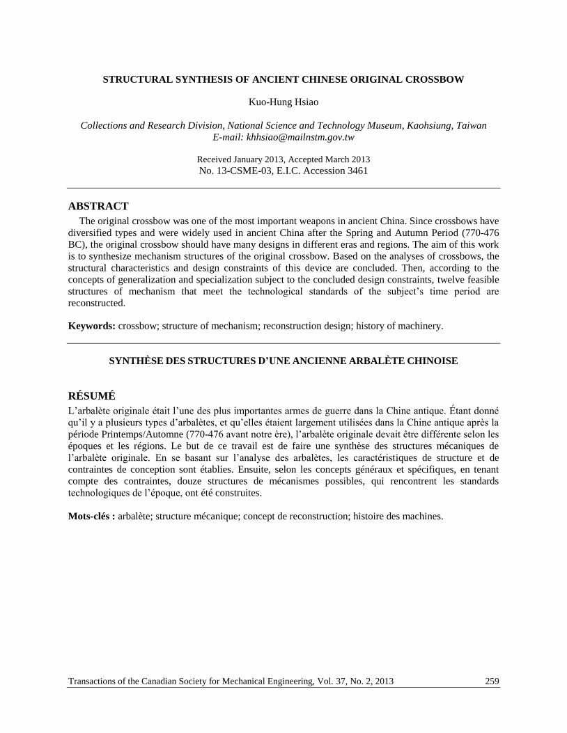
Fig. 8. Structural synthesis of the original crossbow (cont.)
Step 4. The coordinate system is defined as shown in Fig. 1. The function of the trigger mechanism is
to pull the input link and release the bowstring to shoot through the transmission of the percussion link
and connecting link. The uncertain joints may have multiple types to achieve the equivalent function.
Considering the uncertain joints J1 and J2, each one has two possible types and they can not be the
same type simultaneously. When any one joint rotates in z-axis, denoted as JRz, the other one is a cam
joint, denoted as JA.
Considering the uncertain joint J3, it has two possible types. If J3 is a revolute joint, denoted as JRz, J4
must be a cam joint, denoted as JA. And, J5 and J6 have two possible types and they can not be the same
type simultaneously. When any one joint rotates in z-axis, denoted as JRz, the other one is a cam joint,
denoted as JA.
If J3 is a cam joint, denoted as JA, J4, J5 and J6 have two possible types. When any one is a cam joint,
denoted as JA, the others rotate in z-axis, denoted as JRz.
By assigning the possible types of the uncertain joints J1(JRz and JA), J2(JRz and JA), J3 (JRz and JA), J4
(JRz and JA), J5 (JRz and JA) and J6 (JRz and JA) to the specialized chains shown in Figs. 8(d1), (d3) and (d5),
twelve specialized chains with particular identities as shown in Figs. 8(e1)-(e12) are obtained.
Step 5. Figures 8(f1)-(f12) show the corresponding 3D solid models of the feasible designs. Figure 8(g)
shows a prototype of the original crossbow.
6. CONCLUSIONS The original crossbow is a reconfigurable mechanism and was dated back to 600 BC in ancient China.
Since crossbows were popular and widely used in ancient China, the structures of the original crossbow
should have many designs. Through the study of mechanisms and applying the concepts of
generalization and specialization of mechanisms subject to the concluded design constraints, all feasible
specialized chains are generated. By assigning the possible joints to the feasible specialized chains, all
possible structures of the original crossbow are systematically synthesized. The proposed approach not
only can be applied to the original crossbow but also to other ancient mechanisms with diversified types.

Transactions of the Canadian Society for Mechanical Engineering, Vol. 37, No. 2, 2013 271
ACKNOWLEDGEMENTS
The author is grateful to the National Science Council (Taipei, Taiwan) under Grant NSC 101-2218-
E-359-001- for the financial support of this work.
REFERENCES
1. Mao, T.Y., Treatise on Armament (in Chinese), Hainan, Hainan Press, 2001.
2. Zhang, C.H., You, Z.H., Wu, Z.Z., Liu and Y.L., History of Chinese Mechanical Engineering
Invention (in Chinese), Beijing, Tsinghua University Press, 2004.
3. Jingzhou Museum edited, Important Archaeological Discoveries (in Chinese), Beijing, Cultural
Relics Press, 2009.
4. Chen, S., History of the Three Kingdoms (in Chinese), Taipei, Taiwan Commercial Press, 1968.
5. Hsiao, K.H. and Yan, H.S., “Structural Identification of the Uncertain Joints in the Drawings of Tain
Gong Kai Wu,” Journal of the Chinese Society of Mechanical Engineers, Vol. 31, No. 5, pp. 383-
392, 2010.
6. Hsiao, K.H., Chen, Y.H., Tsai, P.Y. and Yan, H.S., “Structural Synthesis of Ancient Chinese Foot-
operated Slanting Loom,” Proceedings of the Institution of Mechanical Engineers, Part C, Journal of
Mechanical Engineering Science, Vol. 225, pp. 2685-2699, 2011.
7. Song, Y.X., Chinese Technology in the Seventeen Century (in Chinese, trans. Sun, E.Z. and Sun,
S.C.), New York, Dover Publications, 1966.
8. Yan, H.S. and Hsiao, K.H., “Structural Synthesis of the Uncertain Joints in the Drawings of Tain
Gong Kai Wu,” Journal of Advanced Mechanical Design, Systems, and Manufacturing - Japan
Society Mechanical Engineering, Vol. 4, No. 4, pp. 773-784, 2010.
9. Hsiao, K.H., Chen, Y.H. and Yan, H.S., “Structural Synthesis of Ancient Chinese Foot-operated
Silk-reeling Mechanism,” Frontiers of Mechanical Engineering in China, Vol. 5, No. 3, pp. 279-288,
2010.
10. Hsiao, K.H. and Yan, H.S., “Structural Synthesis of Ancient Chinese Zhuge Repeating Crossbow,”
Explorations in the History of Machines and Mechanisms, pp. 213-228, Springer, Netherlands, 2012.
11. Hsiao, K.H. and Yan, H.S., “Structural Synthesis of Ancient Chinese Chu State Repeating
Crossbow,” Advances in Reconfigurable Mechanisms and Robots I, pp. 749-758, Springer, London,
2012.
12. Yan, H.S., Creative Design of Mechanical Devices, Springer, Singapore, 1998.
13. Yan, H.S., Reconstruction Designs of Lost Ancient Chinese Machinery, Springer, Netherlands, 2007.