Embed Size (px)
Citation preview

stormwater pollution
prevention
code of practice for the building and
construction industry

MARCH 1999
Authors:
John Botting & Associates
Kathryn Bellette
Published by
ENVIRONMENT PROTECTION AGENCY
Department for Environment,
Heritage and Aboriginal Affairs
GPO Box 2607
Adelaide SA 5001
Telephone 08 8204 2004
Facsimile 08 8204 9393
Free call for country callers 1800 623 4455
ISBN 0 7308 6011 6
© Environment Protection Agency
Permission is granted to reproduce all or part of the publication for non-commercial
purposes, subject to inclusion of an acknowledgement of the source. Copyright
for the design of this publication remains with the
Environment Protection Agency.
Designed by RTFX
Edited by Kathie Stove, in writing
Printed on recycled paper
PREFACEStormwater acts as a carrier for a significant amount of pollution
which is picked up from our private properties and public places,
and transported through street drains and the above-ground
drain–underground pipe network to our waterways and oceans.
The water quality of urban runoff is typically poor because of the
multitude of small pollution sources.
Litter is typically the most visible form of stormwater pollution.
However, contaminants such as sediments, oil and grease, excess
nutrients (eg phosphates and nitrates), organic matter, residual
pesticides and fertilisers all add up to cause an impact on the
environment. This can result in fish kills in streams and estuaries,
unsafe swimming conditions, the accumulation of toxins in aquatic
animals in the food chain or unsightly waterways that degrade our
parks and recreation areas.
In South Australia there is a community expectation that we, as
community members, each have a role in looking after our water
resources. In the driest State in the driest developed continent, we must
make the most of our resource opportunities. Stormwater is increasingly
being used in urban and urban fringe areas for irrigation and industrial
uses, and as a recreational resource, eg the Torrens Lake, West Lakes, the
Patawalonga Lake and our beaches. Domestic rainwater tanks are a
good demonstration of the extent to which we can use clean rainwater
for drinking.
This Building and Construction Industry code is one in a series of
codes for stormwater pollution management in South Australia. It has
been written in consultation with an industry reference group and the
community through a public consultation process.

TABLE OF CONTENTS1 General
1.1 Introduction 11.2 Stormwater or Sewage? 21.3 Guiding Principles 31.4 Industry Education, and Industry Specific 3
Codes of Practice1.5 Site Planning 41.6 Regional Issues 4
2 Legislative Controls 52.1 General 52.2 Environment Protection Act 1993 52.3 Australian Standards 6
3 Operations and Services 73.1 Introduction 73.2 Construction Works 73.3 Operational Activities 123.4 Transportation Activities 183.5 Drainage Design 18
4 Approval Controls 4.1 Land Development and Construction Works 20
5 Soil Erosion and Sediment Control Structures 5.1 General 265.2 Erosion Control Measures 265.3 Sediment Collection Structures 295.4 Soil Erosion and Drainage Management Plan 36
6 Housing, including Home Improvements 6.1 Soil Erosion and Drainage Management Plan 42
6.2 Construction Works—Operational Controls 46

Bibliography 50
Acknowledgements 51
Appendix 1 Relevant Legislation 52 Environment Protection Act 1993 52 Water Resources Act 1997 53 Local Government Act 1934 53 Sewerage Act 1929 54 Soil Conservation and Landcare Act 1989 54 Development Act 1993 54 Other Legislation 55
List of Figures Figure 3.1 Figure 5.1 Figure 5.2 Figure 5.3 Figure 5.4 Figure 5.5 Figure 5.6 Figure 5.7 Figure 5.8 Figure 5.9
Pesticide transformation processes 15 Diversion or catch drain installation method 27 Level spreader installation method 28 Hay bale barrier installation method 30 Silt fence installation method 31 Drop inlet sediment trap 32 Side inlet sediment trap 32 Temporary construction exit 34 Examples of site development measures 35 SEDMP standard symbols 40
Figure 5.10 Single residential development example 40 Figure 5.11 Residential subdivision roadworks 41
Figure 6.1
Figure 6.2
Figure 6.3 Figure 6.4 Figure 6.5
formation example Single residential development 43 example—slight fall Single residential development 43 example—steep fall Silt fence installation method 44 Hardstand driveway 45 Examples of use of diversion channel/bank 46

GLOSSARY OF TERMS
Batter toe drains open channels or swales constructed laterally at the base of a slope to direct runoff away from exposed areas
Catch drains open channels or swales constructed laterally above an exposed cutting to divert runoff into side diversion drains
Catchment area of land that contributes stormwater runoff to a site including under extremely heavy rainfall
Disturbed area that part of a development site that has been disturbed by cut and fill operations to produce an erodible surface
Diversion drains open channels or swales constructed to divert stormwater runoff around exposed areas
Filter fabric tightly woven geotextile fabric used to retain sediments yet allow water to pass through
Filter strip strip of permanent dense vegetation to retard sheet flow and cause deposition of silt
Gabions wire cages filled with rocks
Hydrolysis decomposition of a substance due to chemical action of water
Interstitial water water in between sediment particles
Level spreaders banks and mounds constructed laterally across a slope to convert a concentrated runoff flow into a slower moving shallow widespread flow
Non-point source pollution
pollution from a variety of sources spread over a wide area that arrives at a waterbody or drainage system by less direct methods than for point sources
Off-line structures not built along main drainage lines, but rather off to one side, thus avoiding the need to treat all of the flow
On-line structures placed within main drainage lines, intercepting all of the flows
Photolysis decomposition of a substance by the chemical action of light
Point source pollution
pollution entering the waterbody or drainage system directly from a single discharge point
Sewage treatment works
works for the treatment of wastewater discharge from sewers
Sheet flow runoff flowing in a thin layer across the surface
STEDS a system for the common collection, treatment and disposal of waste—water outflows from septic tanks located on individual properties in some country townships

1 GENERAL1.1 Introduction
This Building and Construction Industry Code of Practice is a voluntary
document. The application of best management practices and process for approvals will be reviewed after twelve months from release of this Code. Even though this document is voluntary, all members of the community have a general environmental duty (refer to section 2)
under the Environment Protection Act 1993 (the Act).
This code covers a range of potential pollution sources from a variety of building and construction industry practices including subdivisional site works. In addition, the code addresses issues related to construction activities that are subject to the approval of relevant authorities. These are mainly confined to construction and building works carried out following the granting of development approval.
The control of site erosion is extremely important during the construction phase of building projects. The quality of stormwater entering our waterways can be greatly influenced by the building and construction industry. This code provides the industry with benchmarks of best practice, based on practices undertaken interstate and overseas.
The code does not contain design details or practices for large scale structural measures such as sedimentation basins and wetlands. These devices require careful design by qualified and experienced engineers and freshwater ecologists. The bibliography contains references to a number of manuals that can help with these design processes.
The four codes of practice for the source control of stormwater pollution are:
Target Audience Primary Objective
Community Control of pollution from the general community.
Local, State and Federal Control of pollution from construction,
Government maintenance and operational activities carried out
by these agencies.
Building and Construction Industry Control of pollution from building and
construction projects.
Industrial, Retail and Control of pollution from activities carried out
Commercial Premises by all industrial, retail and commercial businesses.
Ultimately the Code of Practice will be linked to the Environment Protection (Water Quality) Policy (Water Quality EPP) through the environment protection policy-making process outlined in the Act. This process will establish the appropriate timetable for compliance with specific activities and the penalties for breaches of the Water Quality EPP.
1

The Act will enable prosecution or other appropriate action to be taken when the mandatory practices of the Water Quality EPP are ignored. This code repeats the mandatory provisions of the policy to give the code context. These mandatory provisions are referred to in the code as 'musts'.
Instructional statements within sections 3 to 6 of this code which include the term 'must' can be enforced by the Authority through the use of environment protection orders issued in accordance with the provisions of the Act.
In accordance with procedures which will be laid down in the Water Quality EPP, any changes following a review of this code which relate to sections legally linked to the EPP can only be agreed to by the Minister for Environment and Heritage following consultation with relevant industry, and State and local government authorities and must be published in the government gazette before coming into effect.
In summary, in the code specific objectives, practices and activities are stated as one of the following:
• should, meaning recommended but not mandatory
• must, meaning mandatory practice or requirement.
The use of ‘should’ and ‘must’ in this code will be subject to further discussion during the consultation process of making the Water Quality EPP.
Direct any enquiries on the purpose of this code to the EPA on (08) 8204 2004.
1.2 Stormwater or Sewage? The stormwater drainage system is separate from the sewage system. It is important that we understand the difference. Inside buildings, kitchen, laundry and bathroom drains are connected to the sewer, or to a septic tank in unsewered areas. Outside houses and some offices, a tap over a gully trap may be present which is also connected to the sewer.
All the outside drains including roof drains are connected to the stormwater system.
Rain and other water runs from outdoor drains down the gutters of the roadways into drains under the road which connect to our natural waterways (creeks, rivers and wetlands) or to large open drains and to our beaches, without treatment. Only clean rainfall runoff should enter this system.
The sewer takes wastewater to treatment works, before being piped to the sea or irrigated over land such as golf courses. Strong wastes, like solvents and oils, need treatment at specialised facilities. For the purpose of this code, ‘sewage treatment works’ means works for the treatment of wastewater discharged from sewers, ‘sewer’ means the pipe network used for the common collection of untreated wastewater generated on individual properties in centres with large human populations and ‘septic tank effluent disposal system’ (STEDS) means
2

a system for the common collection, treatment and disposal of wastewater outflows from septic tanks located on individual properties in some country townships.
1.3 Guiding Principles The Code of Practice is based on the following key principles.
Eliminate Non-stormwater Discharges
Stormwater drains should only carry stormwater runoff, and not wastewater or washdown water, rubbish, litter or any other contaminant that can be reasonably prevented from entering the system.
Most built up areas are well served with a sewerage system or a STEDS and waste collection services. Since these provide a very adequate waste disposal system, there is no reason to dump wastes in the stormwater system.
Further information on the disposal of waste to sewer can be obtained from the SA Water Industrial Wastes Section by telephoning (08) 8207 1350.
Control Stormwater Pollution at its Source
It is more cost effective and far preferable to reduce, and where possible eliminate, the causes or sources of stormwater pollution than treat the effects somewhere downstream. Source controls place responsibility directly on the polluter and should lead to long term permanent solutions resulting from simple changes in practice.
Stormwater Runoff is a Resource
Stormwater runoff should be managed as a valuable water resource. Better quality runoff increases the value of the resource and the potential number of uses including ecosystem improvements leading to seagrass conservation, recreational use of waterbodies such as beaches and the Torrens Lake, and alternative sources of water supply.
Maximum Extent Practicable
As the reduction of pollutants in stormwater is technically difficult and costly, this code aims to facilitate the reduction of pollution to the maximum practicable extent by the promotion of best management practices. This will require ongoing active support and awareness by the building and construction industry. The aim is to reduce the volume of pollutants entering the stormwater system in the first place and not incur the costs of clean up.
1.4 Industry Education, and Industry Specific Codes of Practice An extremely important component of the successful implementation of any code of practice is the implementation of an effective workforce education and awareness campaign, for industry planning, design, construction and operational activities.
3

It is anticipated that industries with existing codes of practice will incorporate this Stormwater Code of Practice into those codes. Similarly an industry or business wishing to develop a code of practice can use this Stormwater Code of Practice to form the basis of their recommended water pollution prevention practices.
1.5 Site Planning Section 5.4 outlines those circumstances where a soil erosion and drainage management plan (SEDMP) must be prepared.
The SEDMP should be prepared by the project client as part of the design documentation and included as a tender document. The SEDMP documentation must define the scope of pollution control works required in sufficient detail to enable reliable tender costs to be prepared. Provision will be made, if possible, to allow prospective tenderers to submit alternative strategies and measures where advantages may be demonstrated, provided that the principal aims and objectives (including ‘musts’) of this Code of Practice are maintained.
1.6 Regional Issues This code contains an emphasis on the control of stormwater pollution from sites within built-up areas. In remote areas such as ‘out of council’ regions of South Australia, it is acknowledged that not all features of this code will be relevant.
4

2 LEGISLATIVE CONTROLS2.1 General
This Code of Practice is complemented by legislation aimed at protecting the environment. When using this code, refer, if necessary, to relevant legislation for specific requirements for certain activities. Brief summaries of the more relevant Acts are provided in appendix 1.
Once an EPP is in force, activities related to other Acts must defer to the provisions contained in the EPP.
2.2 Environment Protection Act 1993 General Environmental Duty
Section 25, General Environmental Duty, is one of the underpinning components of the Act and states that:
A person must not undertake an activity that pollutes, or might pollute, the environment unless the person takes all reasonable and practicable measures to prevent or minimise any resulting environmental harm.
Environmental harm is defined as any harm, or potential harm to the environment (of whatever degree or duration) and includes an environmental nuisance. Several strategies can be employed to avoid this, such as the development and adherence to guidelines of best practice provided by codes of practice and EPPs.
In determining the measures required to ensure that all reasonable and practicable measures have been taken to prevent or minimise environmental harm section 25(2) of the Act specifies that regard must be given, amongst other things, to the:
(a) nature of the pollution or potential pollution and sensitivity of the receiving environment; and
(b) financial implications of various measures that might have to be taken, as those implications relate to the class of persons undertaking activities of the same or similar kind; and
(c) current state of technical knowledge and likelihood of successful application of the various measures to be taken.
Enforcement
Although the Authority has a variety of enforcement options under the Act, it is recognised that the general community, industry and other sectors such as local government and other State and Federal agencies need to work together to ensure that complementary outcomes are achieved by increasing environmental performance.
The Act and the Authority foster a keen sense of environmental responsibility on the part of the general community, industry and public authorities such as government agencies, encouraging their active participation in finding solutions and developing innovative approaches to environmental issues. Participation in the development,
5

trial and assessment process for this code and later during the EPP process is one such example. During consultation on the policy, appropriate enforcement arrangements will be determined.
Members of the community, government agencies, industry and other businesses that cause environmental harm or fail to comply with the general environmental duty, can be forced to comply by an Environment Protection Order issued by an officer authorised under section 93 of the Act. An Environment Protection Order may require that a person, or agency, take specified action within a specified period.
A Clean-up Order may also be issued (section 99 of the Act) in place of or in conjunction with an Environment Protection Order.
Failure to comply with these orders can result in maximum fines of:
• $4000 for an Environment Protection Order
• $120,000 for a corporate body and $60,000 for a person for a Clean-up Order.
Civil Remedies
Section 104 of the Act outlines how to apply to the Environment, Resources and Development Court to issue an order on a third person or corporate body. Provisions in this section include the issue of an order restraining a person from engaging in conduct of a particular kind or requiring a person to take specified action, and recovery of expenses from perpetrators of environmental harm for clean-up costs, injury, loss or damages.
2.3 Australian Standards Where appropriate, refer also to any relevant Australian Standards, for example:
• AS 1940–1993 The Storage and Handling of Flammable and Combustible Liquids
• AS 2507–1984 The Storage and Handling of Pesticides
• AS 2508 Safe Storage and Handling Information Cards for Hazardous Materials (various dates depending on the hazardous material)
• AS 3780–1994 The Storage and Handling of Corrosive Substances
• AS 4326–1995 The Storage and Handling of Oxidising Agents
• AS 4332–1995 The Storage and Handling of Gases in Cylinders
• AS/NZS 4452:1997 The Storage and Handling of Toxic Substances
• AS/NZS 3500:1998 3.2 National Plumbing and Drainage— Stormwater Drainage—Acceptable Solutions
6
3 OPERATIONS AND SERVICES
3.1 Introduction The principal objective of the controls to be implemented on building and construction industry operations and services is to minimise the generation of pollutants that may eventually enter the stormwater drainage network.
This section of the Code of Practice covers the works and activities carried out directly by the building and construction industry. These include, but may not necessarily be limited to:
• construction works
• operational activities
• transportation activities.
Also included in this section is a discussion of issues that should be considered during the design of stormwater drainage works.
3.2 Construction Works The generation of sediment, litter and debris during construction works must be minimised.
General
Soil erosion and the generation of sediment during construction activities cannot be entirely prevented. Sound project planning can reduce the potential for erosion but control measures will always be necessary to reduce the impact of erosion both on-site and off-site. The control measures may consist of a combination of construction strategies, structural and vegetative measures, and soil stabilisation techniques. For maximum effect, it is important that all of the control measures implemented must be integrated into the site development plan. The complexity and extent of control measures required will depend largely on the magnitude and duration of the construction activity.
Each construction project should have a SEDMP (see sections 5.4 and 6.1) prepared which should incorporate the following key elements.
• Ensure that the least amount of land is exposed to the risk of erosion for the shortest period of time.
• Effectively control surface runoff entering and leaving the site.
• Effectively control the generation of dust, litter and debris within the site.
• Install erosion control works and measures to minimise the amount of site erosion.
• Install sediment collection devices to prevent the export of sediment from the site.
7
• Rehabilitate all disturbed areas as soon as possible.
• Maintain the erosion control and sediment collection devices.
The methodology, works and measures that can be used to implement these elements are the same as those discussed in section 4.2 Land Development and Construction Works.
General Criteria
In addition to the elements cited above, the following list of objectives should be considered for all types of construction projects.
• Limit site access to nominated and controlled areas.
• Locate and secure all stockpiles away from concentrated water flow paths.
• Ensure that erosion control and sediment collection structures are in place before site clearing work begins.
• Locate sediment traps and basins in locations that will not create adverse flood risks to adjoining properties.
• Clearly specify the conditions under which any of the erosion control or sediment collection structures can be decommissioned.
Road and Rail Construction
The following list of objectives should be considered for road construction projects. Not all these objectives may be appropriate for all conditions.
• Confine access tracks to proposed permanent road locations.
• Grade access tracks to a crown to avoid water concentration.
• Construct access tracks to cross concentrated drainage paths at right angles.
• During the construction of culverts and bridges, divert baseflows around disturbed areas of the site.
• Extend culvert outlets beyond the toe of fill embankments.
• Install energy dissipater structures at the outlets of all culverts where culverts are installed prior to the creation of a downstream stabilised waterway.
• Form regular cross drains to intercept runoff from long cut or fill batter slopes.
• Rehabilitate road shoulders and adjacent swales, preferably with vegetation cover, as soon as practicable.
• Locate road construction stockpiles away from concentrated drainage paths.
• Protect the toe of all stockpiles retained for more than one day with an appropriate silt barrier.
8

Services Installation
The following list of objectives should be considered for service installation works. Not all these objectives may be appropriate for all conditions.
• Install water and sewer services as part of the road construction works.
• Encourage service authorities to install ducting during road construction if these services are to be installed later.
• Avoid works in areas of likely concentrated runoff.
• Divert runoff away from all trench lines with temporary banks constructed from trenching spoil or sandbags.
• Properly compact soil used for trench backfill and rehabilitate the road surface as soon as practicable.
• Locate stockpiles of bedding and backfill material away from concentrated drainage paths, including road gutters.
• Protect the toe of all stockpiles retained for more than one day with an appropriate silt barrier.
Services installed by the direct ploughing method need special consideration if their alignment is across the natural surface contours. Under this method, the trench is not compacted and may be subject to severe erosion from runoff entering the trench and washing the uncompacted material along the trench line. Techniques should be used that minimise this risk, such as direct grout injection at regular intervals along the trench line to create effective barriers and force any soakage water back to the surface and away from the trench.
Plumbing
For plumbing trenching, refer to the next section.
Building Construction Works
All building construction works must be conducted in such a manner so as to minimise the entry of pollutants into the stormwater system. This includes, but is not necessarily limited to, the following building activities and trades.
Hard waste
• All hard waste must be stored on-site in such a manner so as to prevent any materials from entering the stormwater system either by wind or water action. They must be disposed of to a waste depot, licensed to receive that waste.
• Smaller items should be kept in covered bins. They must be disposed of to a waste depot, licensed to receive that waste.
• Consideration should be given to recycling waste wherever facilities for receipt of items are available.
9

Concrete works
• Where possible, all residues and wastes generated by concrete works must be prevented from entering the stormwater system. Where this is not possible, such as in concrete pavement cutting works, the amount of waste that can enter the stormwater system must be minimised.
• On-site mixing of concrete, either by hand or by mechanical means, should be carried out in a designated area of the site which is capable of containing all excess water, residues and waste.
• Where site conditions require the use of concrete pumps from public roadways, temporary bunds must be provided across all downslope gutters to trap any spilt material. All spilt material must be removed from the roadway and gutter before the temporary bunds are removed.
• Concrete mix trucks, pumps and equipment must not be washed down in roadways, footpaths or reserves. These vehicles and equipment should be washed down either within a designated contained area within the site or at a suitably designed and operated depot washdown facility.
• Waste concrete slurry should be allowed to dry and either be disposed of on-site or taken to a licensed waste depot.
Brick works and brick cutting
• Mortar must not be mixed in gutters or any other location, which will drain to the stormwater system.
• All wastewater from brick cutting activities must be prevented from entering the stormwater system.
• Brick cutting activities that generate surplus wastewater should not be carried out on public roads, footpaths or reserves.
• Surplus wastewater from brick cutting activities should be either recycled, disposed to sewer (with SA Water Industrial Waste Section approval) or discharged into a contained area for drying by soakage.
Painting
• Paint waste and wash waters must not be discharged to the stormwater system.
• Water-based paint cleaning water should be disposed of to sewer or diverted into a contained area lined with newspaper on-site. When it is dry, place the newspaper with paint residue in a solid waste bin.
• Oil-based clean up material should be filtered for reuse of the solvent or taken to a waste depot that is licensed to accept these wastes. Place the paint residue after filtering in a solid waste bin.
• Unused paint should be kept in the tin or other sealed container and disposed of to a waste depot licensed to receive this waste.
10

Plastering
• Plastering waste and wash waters must not be discharged to the stormwater system.
• All residues and wastes from plastering activities should be allowed to dry within a designated contained area of the site. Solid waste should be disposed of either on-site or taken to a licensed waste depot.
• Alternatively, solid wastes from plastering activities such as calcium sulphate may be used as a clay modifier in gardens.
Cleaning
• Paint stripping waste, roof cleaning waste and other general building cleaning wastes must not be allowed to enter the stormwater system.
Refer to the High Pressure Water Blasting Code of Practice,
available from the EPA, telephone (08) 8204 2004.
Plumbing
• Site services should be installed in accordance with AS/NZ 3500:1988 3.2 within a reasonable time to minimise runoff to the stormwater system.
Airconditioner installations and cooling tower wastewater
• Evaporative airconditioners must be installed in such a manner so that saline water from the cooler dump valve systems and non-dump valve systems does not enter the stormwater system.
• Cooling towers must be installed so that the tower wastewater is not allowed to enter the stormwater system.
• The saline wastewater from airconditioner dump valve systems and cooling towers should be directed to sewer or to a suitable (saline tolerant) garden area or rainwater tank (if not used for drinking).
Note: Wastewater should not be allowed to exit the site onto a neighbouring
property as this may cause environmental nuisance.
Termite protection
• Physical barriers should be used for termite protection in areas where residuals from spray treatments may enter the stormwater or groundwater systems.
Minor Works
Minor works of construction and maintenance including roads, footpaths, drains and other infrastructure elements must be conducted in a manner that minimises the pollution of stormwater.
The degree of protection will depend on the scope and duration of the maintenance works.
When workers are always on-site during the entire maintenance period, then cleaning of the site using dry sweeping techniques will normally be sufficient.
11

If the works need to be conducted over several days, temporary strategies must be employed to prevent the pollution of stormwater. The strategies to achieve this should include but not necessarily be limited to the following.
• Plan the project so as to minimise the risk of erosion and generation of silt.
• Locate stockpiles kept on-site away from drainage lines and protected from being washed or blown to the stormwater system. Locate hay bale barriers or silt fences (see section 5.3) at the toe of stockpile batters to prevent any loss.
• Protect side entry pits with an appropriate temporary sediment trap during the maintenance period where there is a risk of excavated material being washed into the drainage system (see Stormwater Inlet Pit Traps, section 5.3).
• Construct temporary sediment traps within watercourses where the prevention of the entry of silt and sediment is not practicable (see Sediment Traps, section 5.3).
• Do not undertake on-site equipment servicing and/or clean-ups in areas where contaminants or wastewaters may enter the stormwater system.
• Resurface or stabilise disturbed areas as soon as practicable (see Revegetation, section 5.2).
3.3 Operational Activities The generation of water and wind borne material by any of the building and construction industry’s operational activities on both their clients’ and their own lands must be minimised.
General
Non-stormwater discharges to the stormwater system must not occur from any premises. A thorough site audit should be undertaken of all premises to ensure that this requirement is satisfied. The Authority may approve as a voluntary environmental audit a specified programme of action proposed to be undertaken for the evaluation of the person’s performance in endeavouring to achieve compliance with the Act. Information produced and approved for this purpose is subject to privilege against proceedings under the Act.
The Authority may also enter into an environment performance agreement with any other person or persons.
This agreement may contain terms providing for any matter that the Authority considers appropriate for securing the objects of the Act, including terms binding a party (other than the Authority) to undertake programmes of any kind directed towards the protection, restoration or enhancement of any part of the environment.
All spills and wastes must be disposed to a waste depot licensed to receive that waste or to sewer, if approved by the SA Water Industrial
12

Wastes Section (previously Trade Wastes Section). Spills and wastes can only be disposed to local council STEDS with the formal approval of the relevant council.
Refuelling Facilities
Temporary fuel dispensing areas should be covered. These areas must be isolated from surface runoff generated elsewhere on-site by utilising surface grades, bunds and/or diversion drains.
Refer to the Stormwater Pollution Prevention Code of Practice for Industrial, Retail and
Commercial Premises for requirements of permanent refuelling facilities.
Cleaning or wash waters generated from fuel dispensing areas must not be discharged directly or indirectly to stormwater. All runoff generated from fuel dispensing areas should discharge into a well-maintained separate system, with the necessary pre-treatment facilities for discharge to sewer or a temporary storage facility. SA Water Industrial Wastes Section should be contacted about the proposed installation of any such discharges to sewer.
Employees must be trained to reduce pollution risks by eliminating refuelling spillage.
Workshops
The floor drainage of covered work areas must be isolated from the stormwater system by utilising surface grades, bunds and/or diversion drains. When floor areas are cleaned, dry absorbents and dry sweeping should be used to minimise the generation of wastewater.
Waste or wash water must be pre-treated in a manner approved by SA Water Industrial Wastes Section prior to disposal to the sewer. Any required collection and pre-treatment system must be regularly maintained.
Uncovered Work Areas
Work activities that involve potentially polluting materials such as fuel, oil, grease, coolant, chemicals, solvents and/or cleaning agents that could drain, leak or spill should be relocated to undercover areas which contain pre-treatment devices connected to sewer.
If this is not possible, uncovered work areas must be maintained in a manner that minimises the entry of pollutants from premises into the stormwater system.
For example regularly cleaned and maintained drip pads or containers must be used under vehicles being repaired. Spilt material that could pollute stormwater must not be left unattended but should be cleaned using dry absorbents and dry sweeping wherever possible.
Storage, Loading and Unloading Areas
All hard materials should be stored and handled to avoid contamination of stormwater. Stormwater drainage must be directed around or away from all stockpiles that could potentially cause pollution of stormwater. Hard stockpile areas should either be covered
13
or located in such a manner so as to prevent erosion of the stored material and subsequent pollution of stormwater.
All liquid materials that are potentially hazardous to the environment must be stored and handled carefully to avoid leaks and spills. For large quantities, such materials should be located within a bunded compound. The bund should be:
• impervious to infiltration
• able to safely contain at least 120% of the volume of the largest container located within the bund
• roofed to minimise the collection of rainwater inside the bunded compound.
Liquid handling facilities should be covered and bunded to prevent possible stormwater contamination as well as to assist in the control of any spills.
Vehicle, Plant and Equipment Cleaning Areas
Waste or washdown water from the cleaning of vehicles, plant and/or equipment must not be allowed to discharge to the stormwater system.
These activities should be carried out in a covered area that discharges all wastewater to sewer with approval from SA Water Industrial Wastes Section.
Refer to the Stormwater Pollution Prevention Code of Practice for Industrial,
Retail and Commercial Premises for requirements of permanent vehicle plant and
equipment cleaning areas.
Parking Areas
Property owners should be encouraged to establish car parks with permeable surfaces. These may include:
• lattice paving with grassed or gravel ‘windows’
• traditional paving laid out to incorporate grassed or gravel ‘windows’
• gravel or other firm, pervious material.
Impervious parking areas and paved open areas discharging to the stormwater system should be regularly dry swept. These areas should be fitted with devices capable of preventing litter and sediment from entering the stormwater system.
For large carparks such as those in shopping centres, grease and oil separators should be installed within the internal drainage system to remove pollutants regularly washed off the parking areas.
Opportunities should be used to direct runoff from parking areas on to vegetated filter strips before discharge into the stormwater system.
Hard Waste Disposal, Landfill and Borrow Pit Sites
The operation of all solid waste disposal sites, landfills and borrow pits must be carried out so as to prevent the pollution of surface water, including stormwater.
14
Areas that could give rise to contaminated runoff should be isolated from uncontaminated areas. Stormwater from surrounding areas should be excluded from or diverted around the site of any potential contamination. Where a watercourse traverses an area of potential contamination, it should be protected from contamination by appropriate measures including lining, enclosure, cutoff banks and/or vegetated buffer zones.
Any surface water discharged from a contaminated area must be collected and stored for assessment and/or treatment prior to release from the site.
Note: A specification which landfill licensees are required to follow, entitled
Specification for Surface Water Sampling at South Australian Landfills is available from
the EPA. This document outlines the requirements of metropolitan landfill
licensees when undertaking a surface water runoff monitoring programme at
designated landfill sites. It should be referred to by landfill site operators.
Pesticides
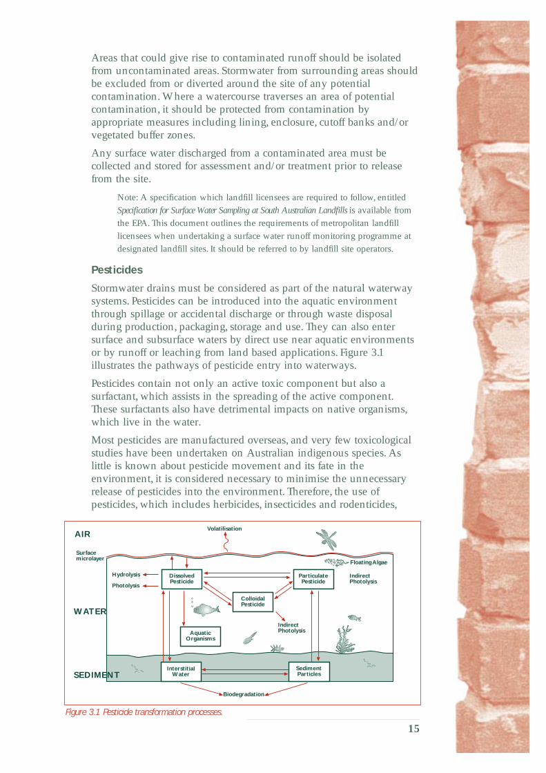
Stormwater drains must be considered as part of the natural waterway systems. Pesticides can be introduced into the aquatic environment through spillage or accidental discharge or through waste disposal during production, packaging, storage and use. They can also enter surface and subsurface waters by direct use near aquatic environments or by runoff or leaching from land based applications. Figure 3.1 illustrates the pathways of pesticide entry into waterways.
Pesticides contain not only an active toxic component but also a surfactant, which assists in the spreading of the active component. These surfactants also have detrimental impacts on native organisms, which live in the water.
Most pesticides are manufactured overseas, and very few toxicological studies have been undertaken on Australian indigenous species. As little is known about pesticide movement and its fate in the environment, it is considered necessary to minimise the unnecessary release of pesticides into the environment. Therefore, the use of pesticides, which includes herbicides, insecticides and rodenticides,
SEDIMENT
Surface
Colloidal
Aquatic Organisms
Interstitial Sediment
Biodegradation
Floating Algae
AIR Volatilisation
microlayer
Photolysis
Hydrolysis Particulate Pesticide
Dissolved Pesticide
Pesticide
Water Particles
Indirect Photolysis
Indirect Photolysis
WATER
Figure 3.1 Pesticide transformation processes.
15

should be undertaken in conjunction with a strategic integrated pest management plan.
An integrated management plan may involve, for example, the physical removal of plants and physical trapping of animals at optimum times of the year. In the case of plants, care must be taken not to disturb watercourse banks as much as practicable and to replace the pest species with preferred vegetation as soon as possible to both prevent erosion and reinfestation of pest plants.
The following guidelines should be adopted for the management of pesticides:
• Apply herbicides during the early growth phase of the target plants before flowering (thereby preventing cross pollination with other stands of pest vegetation in the area and also eliminating seed set).
• Follow herbicide use with physical weed removal and replacement preferably with indigenous vegetation suitable to that location, or other plants of councils’ choice. Non-pest grass species may be useful to stabilise banks until the preferred vegetation establishes. It is imperative to avoid the reinstatement of pest plants. This will require covering the ground as soon as possible with the replacement vegetation and or matting. Again, the period of growth (autumn/spring for most plants) is a suitable time for revegetation. This corresponds well with spraying at the beginning of the growth period.
• The timing of application is important to eliminate the need for continual use of the herbicide. Do not use during periods of rain. Plants generally require 24 hours to absorb the herbicide through the leaves. If rain occurs in the meantime, the herbicide may not effectively kill the target vegetation and may be washed off and enter the stormwater system. This can be a particular problem for pre-emergent sprays such as atrazine if applied to soils.
Note: Pre-emergent sprays have a greater residual period in soils
than adult sprays.
• Use wanding and painting on to leaves or, for woody weeds, cutting and painting or injection methods of application, where possible, in preference to spraying, to minimise spray drift. For deciduous trees, it is preferable to inject the herbicide immediately after leaf drop to prevent the possibility of herbicide transfer into waterways through the leaf litter.
• Avoid application of herbicides in areas surrounding and within watercourses. If considered necessary, this should be done in consultation with the EPA.
Note: Very few pesticides are registered for spraying in watercourses.
• Do not spray under windy conditions. The wind may transport spray to non-target species and stormwater systems.
• The use of pre-emergence insecticides such as Bti is preferred ahead of adult treatment. Pre-emergence insecticides have the advantage of gradually decreasing the source by preventing the development of breeding stock.
16

• Rodenticide baits should be placed away from waterways.
• The storage of pesticides and accidental spill contingency plans should be as for all hazardous chemicals (see Storage, Loading and Unloading Areas, section 3.3).
• All herbicides should be coloured with a suitable non-toxic dye to indicate where they have been used.
• Unwanted chemicals must be disposed of at a waste depot licensed to receive the waste, and not tipped into the stormwater system.
• Empty chemical containers must be triple rinsed and punctured before disposal.
• All applications should follow manufacturers’ handling and safety instructions.
Spills, Clean-up Procedures
Any property that contains hazardous and/or potentially polluting material should have an emergency spill response plan.
A copy of the material safety data sheets must be readily available for all materials on-site.
Spills must not be washed into the stormwater system.
All sites that deal with potentially polluting material should prepare spill response procedures, train employees and provide appropriate clean-up materials. As a minimum, a basic spill response procedure must make employees aware of the need to contain spills and not to wash spills into the stormwater system.
In the event of a spill, the spill source should be quickly and safely stopped and the spilt material isolated and contained from the stormwater system and waterways. The spill must be cleaned up with reference to the material safety data sheets.
The preparation and ongoing maintenance of a emergency spill response plan is seen as necessary for the purposes of showing compliance with the general environmental duty.
Emergency Response to Spill or Leakage of Hazardous Material
Help and advice must be sought from the appropriate emergency authorities for large or hazardous spill incidents.
In the first instance, notify the South Australian Police of a hazardous material incident.
As prescribed by the Act, the EPA must be notified as soon as practicable of all events or conditions causing or threatening serious or material environmental harm.
E PA telephone (08) 8204 2004 during office hours.
The Act provides for a range of penalties in relation to various forms of pollution, including failure to notify.
17
Demolition
Demolition activities must be undertaken in a manner, which does not allow demolished materials to enter the stormwater system. Activities covered by this code must be adhered to. For instance uncovered work areas, storage, loading and unloading, vehicle plant and equipment cleaning areas outlined in section 3, and sediment and erosion control measures outlined in section 5.
Surface water runoff from contaminated sites must not enter the stormwater system, nor be directed to underground aquifers.
3.4 Transportation Activities The loss of materials on to roads during transportation must be minimised. This applies to both construction and maintenance activities.
The transportation of all goods and materials by the building and construction industry and/or its nominated contractors must be carried out in such a manner so as to prevent accidental spills and leakage.
Loads that may be subject to loss through wind erosion or accidental spillage must be totally and securely covered or sealed. Loose material should be cleaned from trucks before they leave the site.
When loading and unloading, prevent spillage of materials on to the road. Any accidental spills must be cleaned up immediately so as to prevent the material from entering the stormwater system.
3.5 Drainage Design Stormwater drainage systems must be designed in accordance with an integrated catchment management plan and incorporate best management practices.
In relation to the control of stormwater pollution, a number of works and measures should be considered. These will vary between catchments and may include but are not necessarily limited to the following.
• Retain natural creek and waterway systems wherever possible to promote the natural filtering and pollutant removal processes and help prevent scouring and erosion.
• Rehabilitate degraded creek and waterway systems to achieve the same objective.
• Implement scour and erosion protection strategies and devices along the waterway system. Particular attention should be paid to the protection works necessary at the outlet of all high velocity drainage systems.
• Incorporate water quality improvement works, such as sedimentation basins, inlet pit baskets, trash racks, pollution removal devices and wetland systems as an integrated part of the complete drainage system.
18

• Protect ecologically sensitive areas from the erosion and pollution potential of stormwater runoff as follows:
– Remnant bushland and open space areas should be protected from the impact of stormwater runoff.
– Velocity dissipaters should be placed at the exit of all concentrated stormwater discharges to create non-erodible conditions in the downstream watercourse.
– Watercourses may need to be stabilised immediately downstream of stormwater outlets to allow for the transition of high velocity flows to non-erodible velocities.
– Level spreaders should be used to convert concentrated stormwater flows into shallow sheet flows that discharge across stable vegetated areas.
– The discharge of all forms of pollutants should be minimised from the stormwater prior to discharge into the sensitive areas. This includes, but is not necessarily limited to, the removal of excess nutrients, silt, organic matter containing pest species and litter.
19

4 APPROVAL CONTROLS4.1 Land Development and Construction Works
Erosion and subsequent sedimentation that can potentially occur during land development and construction works must be minimised as much as practicable.
General
Land development is the most critical stage for the generation of sediment pollution. Sediment eroded from development and construction sites may cause damage to adjacent properties, block stormwater systems and be deposited in creeks, dams, lakes and eventually the marine environment. This section of the code defines the requirements that should be adopted as part of a soil erosion control strategy during land development and construction works.
Since these are minimum guidelines only, special site and environmental conditions could require a greater level of protection than contained in this code.
Compliance with these requirements does not remove the obligation of the developer or designer to exercise the necessary general environmental duty of care.
Consideration must also be given to minimising the potential for soil erosion downstream of any development site, both during the construction period and following its completion. This may occur as a result of the concentration of flow paths, increased peak flow rates and duration of runoff because of the addition of impervious areas and extended periods of low trickle flows that have continuously wet the soil.
The key elements of a soil erosion control strategy are:
• construction planning (in terms of design and timing) to minimise the risk of erosion
• installation of erosion control structures and strategies
• installation of sediment collection structures
• stabilisation and rehabilitation of all disturbed areas.
For many land development projects, these elements can be implemented through the use of relatively simple and low cost measures.
The following major development and construction activities have been identified as requiring appropriate soil erosion control strategies to ensure that the minimum amount of silt, litter or debris leaves the site:
• subdivision projects
• large site developments
• road and transport projects
• underground utilities
20
• building projects, including carparks
• channels and floodways
• recreational facilities, eg ovals
• site remediation.
Construction Planning and Practice
Development costs associated with erosion and sediment control can be minimised by planning to cater for the physical limitations and constraints of the site. Such planning approaches include but are not necessarily limited to:
• avoiding areas for development with high to extreme erosion hazard potential
• scheduling earthworks so as to retain, at all times, as much protective groundcover as possible
• programming slope stabilisation and revegetation works to follow as soon as possible after the completion of earthworks formation
• minimising the amount of site disturbance beyond the limit of approved development works.
Advise all site contractors of the strategy and action to be taken.
As construction work progresses, site erosion must be minimised by adopting practices such as the following:
• controlling drainage from outside the site so that it is diverted around all disturbed areas
• controlling drainage on the site by intercepting and redirecting runoff to protect all exposed areas
• using simple, temporary measures, where appropriate, to treat runoff from small areas that may be exposed for only a short period of time
• installing erosion and sediment control structures before commencing site disturbance and construction works
• retaining topsoil for later use in revegetation works. The topsoil should be stockpiled on-site outside all drainage path lines.
Spoil heaps kept on-site should be covered with tarpaulins or if long term, stabilised with vegetation either through natural regeneration or, if this does not happen, through seeding with a sterile, non-seed-setting vegetation cover. All spoil heaps should be surrounded by a silt fence at the toe of the stockpile (see section 5.3).
During the construction period, provision must be made on-site for the orderly collection and temporary storage of all site debris and waste. This storage facility should be located away from all drainage paths to prevent litter and debris from entering the stormwater system. The storage facility must be kept covered at all times if it contains material capable of being wind blown.
21

Erosion Control Structures and Strategies
Erosion control structures must be installed and erosion control strategies must be implemented, in order to significantly reduce the need, size and hence cost of the sediment collection structures.
These structures and strategies should include but are not limited to:
• locating catch drains that direct runoff to diversion drains at the top of proposed cuttings where adjacent land drains towards the cutting
• constructing diversion drains to protect slopes by directing intercepted surface water to a stable outlet
• constructing batter toe or catch drains to collect runoff from batter slopes and directing it to drainage systems or natural watercourses
• constructing level spreaders to convert a concentrated flow of runoff into sheet flow at a non-erosive velocity on to an undisturbed area stabilised with vegetation
• rehabilitating all disturbed areas that are not built on or otherwise developed within 14 days of final land formation for each area
• keeping all exposed ground surfaces damp to minimise dust emission and, if that is not practicable, installing a 40% porous (eg 60% shade cloth) wind break fence on the windward side of the site which will be effective over a distance approximately 15 times its height
• establishing a temporary cover of a dense ground crop using sterile, non-seed-setting species (such as barley wheat) on all disturbed areas that will otherwise remain exposed for more than 14 days before permanent stabilisation works are undertaken.
These works are discussed in further detail in section 5.2
Sediment Collection Structures
Devices must be installed to remove sediment from the runoff before it leaves the site. These devices may be temporary, for use only during the construction period, or permanent.
The sediment collection structures must be designed so that they will not be overtopped by events more frequent than the estimated 1 in 5 year Average Recurrence Interval storm. The devices must be installed before the development begins.
The structures require regular inspection and maintenance and should always be checked after each significant runoff event for damage or clogging by silt and debris.
The devices discussed in section 5.3 of this Code of Practice are included as a representative sample of the available structures. Typical guideline values for their scope of application are given for average conditions. These may be used in the absence of any more detailed information. Measures should be selected that are the most appropriate for the hydrological and geophysical conditions that prevail at each site.
22

Sediment collection structures have the potential to create stagnant pools of water that could attract pests such as mosquitoes and rodents. It is important that any permanent wet areas be accessible to within at least 1.0 metre in case baiting is required for pest control purposes.
Sediment collection structures should include but are not necessarily limited to the following.
• Interception filter devices such as hay bale barriers and silt fences may be placed across minor drainage lines to filter sediment from runoff from small areas and are typically suitable for development sites where the disturbed area is less than 0.5 ha.
• Temporary construction exit pads should be installed at all exits from the site to prevent the transportation of sediment, cement dust etc on to public roads from vehicle tyres, chassis and sides.
• Sediment traps constructed from hay bales or gabions may be used to allow settling of sediments from small construction sites where the disturbed area is less than 1.0 ha. Stone weirs comprising a core of hay bales or stone contained by a timber framework on either side may be used for larger construction sites.
• Filter strips of vegetation, comprising tall dense grasses, may be used as simple, effective and economical sediment traps; the flatter (ground slope) and wider the filter strips are, the greater their ability to trap sediment.
• Sedimentation basins may be temporary, semi-permanent or permanent, depending on the size and nature of the development. The basins should be constructed off-line and used to collect sediment laden runoff generated from the construction site.
– Temporary sedimentation basins should be used where the disturbed construction area exceeds 0.5 ha but is less than 2.0 ha and the entire site will be completely developed at the end of the proposed construction works.
– Semi-permanent sedimentation basins should be used where the disturbed construction area exceeds 0.5 ha but is less than 2.0 ha and the entire site will not be completely developed at the end of the proposed construction works. This would apply to any staged development proposal or land subdivision application.
– Permanent sedimentation basins, incorporating a gross pollutant trap, should be used for either of the following conditions:
• The disturbed construction area exceeds 2.0 ha and permanent source control measures are not provided as part of the development.
• The application includes parking areas for more than ten vehicles and a grassed or vegetated filter strip is not provided to treat runoff from the parking area.
23

– All sedimentation basins should be sized in accordance with a specified maintenance interval.
Stabilisation and Rehabilitation of all Disturbed Areas
Vegetation is the most effective erosion and sediment control measure for all surfaces that will remain unsealed. Therefore, the reestablishment of the vegetation cover on all disturbed areas, as soon as practicable, is a critical element of any soil erosion and sediment control strategy.
Permanent vegetation should be progressively established on all disturbed areas as each stage is completed to the point where no further construction activity will occur. These rehabilitation areas should be maintained and protected from any damage from activities on adjoining parts of the site. Revegetation is discussed further in section 5.2.
Where practicable, runoff from potentially polluted surfaces should be discharged onto a suitable vegetation filter strip before the stormwater leaves the site. Otherwise, a stormwater treatment device must be fitted capable of removing litter, sediment and oil products from the runoff.
Permanent water quality improvement structures (such as sedimentation basins or artificial wetlands) should be provided as a part of any development works where detrimental impacts would occur downstream of the site. These structures may need to be multipurpose in nature not only to remove pollutants from stormwater discharges but also to reduce peak flow rates and velocities to within non-erodible limits.
Dust Emissions
Dust can cause significant nuisance to nearby residents and can cause pollution of stormwater.
Dust emissions from the site should be controlled so as to minimise any adverse effect on an amenity value of an area.
To this end all roadways, entrances and main traffic areas to a site should be compacted, sealed or coated with a dust suppressant or mist spray regularly to minimise dust. Particular care should be taken during the site preparation phase because of the potential for considerable disturbance to the ground surface.
Note: Oil must not be used as a dust suppressant.
Protection and Maintenance of Watercourses
Under section 634 of the Local Government Act 1934, councils are responsible for the protection of all watercourses within their areas.
Unless authorisation is given by the relevant council:
• nothing can be deposited in a watercourse
• watercourses may not be obstructed
• the course of watercourses may not be altered
24

• nothing can be removed from the bed and banks of a watercourse.
In situations where the development is associated with a natural waterway, the watercourse should be retained as a natural waterway or, if the opportunity arises, improved through weed control, revegetation and/or bank stabilisation.
The advantages of retaining the natural watercourse are:
• decreased velocity of flow
• prevention of erosion
• improved water quality
• increased adjacent property values
• provision of native wildlife habitat.
25

5 SOIL EROSION ANDSEDIMENT CONTROL STRUCTURES
5.1 General This section of the code contains a brief description of the soil erosion and sediment control structures referred to in this code. Further details on the design and implementation of these measures and devices can be obtained from the reference texts and manuals listed in the bibliography.
The selection of appropriate controls and measures, and the design details of the structures must be made with reference to the geological, soil, landform and hydrological characteristics of the site. Not all measures and devices will be applicable for all sites. Treatment devices should be selected so as to achieve the principal objectives of this code.
5.2 Erosion Control Measures
General
Measures described in this section are source controls that limit the amount of site erosion. The measures rely on the principles of limiting runoff velocities and stabilising disturbed surfaces to limit erosion. The appropriate controls, or combination of controls, should be selected to suit the relevant site conditions.
Catch/Diversion Drains
Catch or diversion drains (see figure 5.1) are channels constructed across a slope to convey runoff at a non-erosive velocity. The channel may be combined with an embankment on the downslope side to increase its capacity. The drains intercept the sheet runoff and divert it at a non-scouring velocity to a stabilised outlet.
Diversion drains (see figure 5.1) are used to direct flow from upslope catchments around disturbed areas. The drains may also be used where long cut or fill slopes need to be reduced into shorter non-erodible sections, by intercepting sheet runoff and directing it across the slope to discharge on to a stabilised area. The channels require construction on a relatively flat grade to minimise velocities and prevent scour. Channel stabilisation measures should be used where this is not achievable.
Diversions of runoff around disturbed areas minimise the quantity of runoff requiring treatment for the removal of sediment. Drains across disturbed slopes intercept overland sheet flow and reduce its sediment load. The drains are relatively easy and cheap to construct where earthmoving equipment is available on-site.
26

Revegetation
Revegetation, by providing a dense groundcover, is widely accepted as an effective means of reducing soil erosion from disturbed sites. A range of methods is available to establish a vegetation cover for the control of scour. The methods function by protecting the soil surface from rain impact, increasing infiltration, reducing runoff velocity, binding the soil and filtering runoff. Revegetation should not be expected to provide complete erosion protection for a soil that is not stable due to its inherent structure, texture or excessive slope. Erosion control matting should be used on all revegetation areas on excessive slopes to provide interim protection until the vegetation cover can be fully established.
Natural surface
top width 0.5 m minimum
1.0 m minimum
1 1
1 2.5
0.5 m
Compacted earth bank,
0.3 m minimum 2.5 m minimum
minimum
2.5 m minimum
Figure 5.1 Diversion or catch drain installation method.
Revegetation of all disturbed areas should be carried out as soon as is practicable following the completion of earthworks. The measures may be applied on a broad scale to control erosion from a large area, or they may be applied to a more localised extent to protect newly constructed formations against scouring effects. All revegetation areas should be adequately fenced to prevent damage from adjacent activities.
Level Spreaders
A level spreader (see figure 5.2) is a structure built across the slope at the outlet of a channel or drain, which has a wide level overflow sill discharging on to an undisturbed area stabilised by vegetation cover. The purpose of the level spreader is to convert a concentrated, potentially erosive outflow from a drain or channel into non-erosive sheet flow.
Level spreaders are generally used at the outlet of diversion channels. However, they may be more widely used in general drainage practice at the outlet of any concentrated discharge.
The spreaders require careful construction to ensure that the outlet sill is level over its entire length. They can only be used in locations where the overflow sill can be constructed on undisturbed soil. The level spreader needs to be constructed such that the sill is parallel to the slope and discharges on to a stabilised vegetated area. Discharge from the sill should only be allowed as shallow, slow moving sheet flows.
27
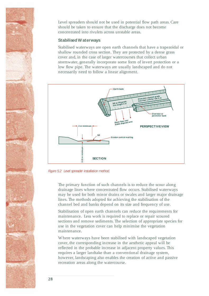
Level spreaders should not be used in potential flow path areas. Care should be taken to ensure that the discharge does not become concentrated into rivulets across unstable areas.
Stabilised Waterways
Stabilised waterways are open earth channels that have a trapezoidal or shallow rounded cross section. They are protected by a dense grass cover and, in the case of larger watercourses that collect urban stormwater, generally incorporate some form of invert protection or a low flow pipe. The waterways are usually landscaped and do not necessarily need to follow a linear alignment.
perimeter bank
Sheet flow over
stable disposal area
Sill at 0% grade,
min length 4 m
Diversion channel grade
less than 1.0% for last 6 m
SECTION
Sill
Earth bank
PERSPECTIVE VIEW
Diversion or
Erosion control matting
2 m minimum
0.15
m m
inim
um
Figure 5.2 Level spreader installation method.
The primary function of such channels is to reduce the scour along drainage lines where concentrated flow occurs. Stabilised waterways may be used for both minor drains or swales and larger major drainage lines. The methods adopted for achieving the stabilisation of the channel bed and banks depend on its size and frequency of use.
Stabilisation of open earth channels can reduce the requirements for maintenance. Less work is required to replace or repair scoured sections and remove sediments. The selection of appropriate species for use in the vegetation cover can help minimise the vegetation maintenance.
Where waterways have been stabilised with landscaped vegetation cover, the corresponding increase in the aesthetic appeal will be reflected in the probable increase in adjacent property values. This requires a larger landtake than a conventional drainage system, however, landscaping also enables the creation of active and passive recreation areas along the watercourse.
28

5.3 Sediment Collection Structures
General
Measures described in this section are small scale devices for use on construction sites to remove sediment from site runoff. Most of the measures would normally be temporary in nature, being required only until the disturbed surfaces in the catchment they serve have become permanently stabilised, usually by revegetation.
The appropriate controls, or combination of controls, should be selected based on the expected rate of sediment export and the duration of the construction works. All sediment control structures will require regular inspection and periodic maintenance and/or replacement. Care must be exercised to ensure that the sediment removed from the structures during maintenance operations is not allowed to be remobilised and exported from the site.
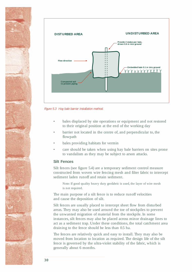
Hay Bale Barriers
Hay bale barriers (see figure 5.3) are a temporary sediment control device. They are constructed from bales of hay positioned so as to intercept sediment laden runoff and retain the sediment. The primary purpose of a hay bale barrier is to reduce runoff velocities and filter runoff, thus causing the deposition and removal of silt.
Hay bale barriers may be placed across minor drainage lines to filter runoff from small catchment areas of up to 0.5 ha in size. Hay bales may also be used as a temporary perimeter bank around disturbed areas preventing runoff from leaving the disturbed area without being treated. The barriers may also be placed around stormwater inlet pits, particularly during the construction phase of a development, to prevent sediment entering the underground drainage system.
Hay bale barriers are relatively inexpensive and are easy to install. However, the bales only have a three month life span and therefore require regular inspection and repair or replacement. It is important to ensure that the hay bales do not contain any potential pest plants.
Bales used on development sites can be utilised as mulch when their useful life as a barrier is finished.
Hay bale barriers should be inspected after each rain event for displacement, undercutting and overtopping, and repaired immediately. Experience has shown that most hay bale barrier failures are related to the following installation and related problems:
• bales not staked firmly into the ground
• bales not embedded into the ground
• bales not butted tightly end-to-end
• insufficient space provided for sediment entrapment
• access for cleaning not provided
29
DISTURBED AREA UNDISTURBED AREA
Compacted soil
Flow direction
to prevent piping
Embedded bale 0.1 m into ground
Provide 2 stakes per bale, driven 0.6 m into ground
Figure 5.3 Hay bale barrier installation method.
• bales displaced by site operations or equipment and not restored to their original position at the end of the working day
• barrier not located in the centre of, and perpendicular to, the flowpath
• bales providing habitats for vermin
• care should be taken when using hay bale barriers on sites prone to vandalism as they may be subject to arson attacks.
Silt Fences
Silt fences (see figure 5.4) are a temporary sediment control measure constructed from woven wire fencing mesh and filter fabric to intercept sediment laden runoff and retain sediment.
Note: If good quality heavy duty geofabric is used, the layer of wire mesh
is not required.
The main purpose of a silt fence is to reduce runoff velocities and cause the deposition of silt.
Silt fences are usually placed to intercept sheet flow from disturbed areas. They may also be used around the toe of stockpiles to prevent the unwanted migration of material from the stockpile. In some instances, silt fences may also be placed across minor drainage lines to act as a sediment trap. Under these conditions, the total catchment area draining to the fence should be less than 0.5 ha.
The fences are relatively quick and easy to install. They may also be moved from location to location as required. The design life of the silt fence is governed by the ultra-violet stability of the fabric, which is generally about 6 months.
30

Silt fences are also commercially available, offering complete prefabricated systems and greater ultra-violet stability
DISTURBED AREA UNDISTURBED AREA
0.5–0.6 m
posts or 1.5 kg/m steel posts
filter strip
Geofabric and wire mesh buried 0.2 m into ground. On rocky ground, set into concrete plinth or sufficiently weighted down
Flow direction
Provide stakes at 2.0 m max spacing' driven 0.5–0.7 m into ground Stakes to be 0.1 m diameter timber
Fasten wire mesh to stakes with heavy duty wire staples.
Fix Geofabric to wire mesh joints to have min 0.3 m overlap and either sewn or attached stakes
Vegetated
Figure 5.4 Silt fence installation method.
Stormwater Inlet Pit Traps
Stormwater inlet pit traps are temporary devices used to prevent silt from entering stormwater drainage pipes during construction or maintenance works. Care should be taken when installing these devices to ensure that total blockage of the approach to the inlet pit does not create a risk of flooding adjacent properties.
Two basic types of inlet pit traps can be used, one for drop inlets (see figure 5.5) and the other for side entry inlets (see figure 5.6). Both are constructed from heavy gauge wire netting or mesh that supports a geotextile filter fabric. The filter fabric is protected and held in place by being covered with a 50–75 mm layer of gravel, preferably prewashed.
A semi-portable version can be manufactured for use in both cases. This consists of a long ‘sausage’ manufactured from the wire netting, filter fabric and gravel. It can be laid around the approach to both types of inlets or used as a series of interceptors laid diagonally across road gutters. Ordinary house bricks can be used as spacers to set the filter sausage back from the face of the inlet. In this manner, the filter device can be overtopped during flood events.
The small scale of these devices means they need frequent cleaning to remain effective for long periods. They are ideal for use during short-term maintenance projects.
31

Silt laden runoffSilt laden runoff
12 mm pitch
0.5 m
50–75 mm gravel, 0.2 m minimum depth
Filtered water
Geotextile filter fabric
Heavy gauge wire mesh
minimum
Alternatively, drop inlet may besurrounded by hay bale barriersor a silt fenceRefer to relevant details
Figure 5.5 Drop inlet sediment trap.
12 mm pitch
Silt laden runoff
Filter fabric
0.3 m
Heavy gauge wire mesh
50–75 mm gravel
Concrete gutter
Wire mesh
Gravel
Filtered water
Geotextile filter fabric, fixed to rear side of batten
Provide 80 mm x 50 mm batten spaced 50 mm from kerb face and 70 mm from watertable
Semi-portable version (sealed both ends)
Figure 5.6 Side inlet sediment trap.
Sediment Traps
Sediment traps are temporary structures used to intercept runoff and capture silt. The traps take a number of forms but usually involve the excavation of a small basin and the creation of an embankment along its downhill side. The primary function of the sediment trap is to capture a concentrated sediment laden flow and store it under quiescent (still) conditions. This allows the silt to be deposited in the bottom of the trap.
Sediment traps are located on drainage lines downstream of small catchment areas where a high sediment load is expected to be generated. (For low sediment load cases, hay bale barriers or silt fences may be more suitable.) The traps must be installed before any land clearing operations
32
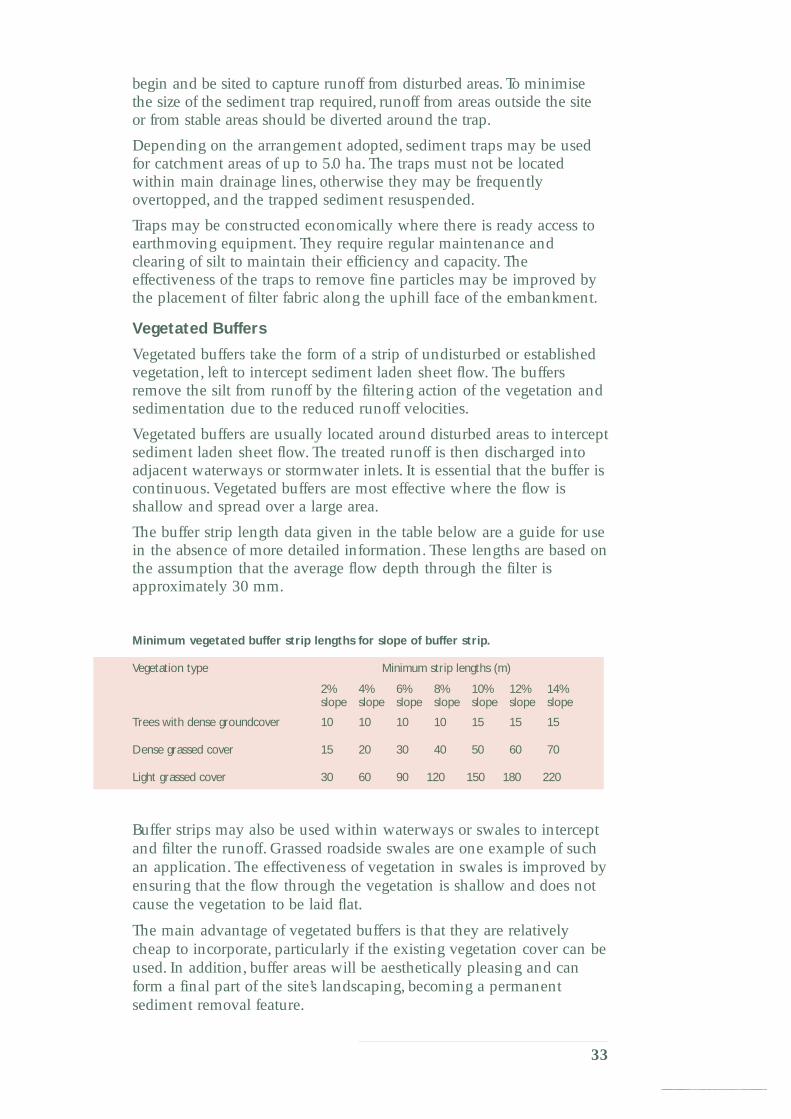
2% 4% 6% 8% 10% 12% 14% slope slope slope slope slope slope slope
10 10 10 10 15 15 15
15 20 30 40 50 60 70
30 60 90 120 150 180 220
33
begin and be sited to capture runoff from disturbed areas. To minimise the size of the sediment trap required, runoff from areas outside the site or from stable areas should be diverted around the trap.
Depending on the arrangement adopted, sediment traps may be used for catchment areas of up to 5.0 ha. The traps must not be located within main drainage lines, otherwise they may be frequently overtopped, and the trapped sediment resuspended.
Traps may be constructed economically where there is ready access to earthmoving equipment. They require regular maintenance and clearing of silt to maintain their efficiency and capacity. The effectiveness of the traps to remove fine particles may be improved by the placement of filter fabric along the uphill face of the embankment.
Vegetated Buffers
Vegetated buffers take the form of a strip of undisturbed or established vegetation, left to intercept sediment laden sheet flow. The buffers remove the silt from runoff by the filtering action of the vegetation and sedimentation due to the reduced runoff velocities.
Vegetated buffers are usually located around disturbed areas to intercept sediment laden sheet flow. The treated runoff is then discharged into adjacent waterways or stormwater inlets. It is essential that the buffer is continuous. Vegetated buffers are most effective where the flow is shallow and spread over a large area.
The buffer strip length data given in the table below are a guide for use in the absence of more detailed information. These lengths are based on the assumption that the average flow depth through the filter is approximately 30 mm.
Minimum vegetated buffer strip lengths for slope of buffer strip.
Vegetation type Minimum strip lengths (m)
Trees with dense groundcover
Dense grassed cover
Light grassed cover
Buffer strips may also be used within waterways or swales to intercept and filter the runoff. Grassed roadside swales are one example of such an application. The effectiveness of vegetation in swales is improved by ensuring that the flow through the vegetation is shallow and does not cause the vegetation to be laid flat.
The main advantage of vegetated buffers is that they are relatively cheap to incorporate, particularly if the existing vegetation cover can be used. In addition, buffer areas will be aesthetically pleasing and can form a final part of the site’s landscaping, becoming a permanent sediment removal feature.

The effectiveness of vegetated buffers is dependent on the ground slope, catchment size and density of vegetation. Dense strips of vegetation in waterways increase roughness and the size of the waterway needs to be increased to compensate for the loss of hydraulic capacity.
Temporary Construction Exit
Temporary construction exits (see figure 5.7) should be installed at any point where traffic will be leaving a construction site. The function of the construction exits is to minimise the transportation of sediment from construction sites on to public roads or adjacent properties via the wheels, chassis and sides of vehicles. Temporary construction exits consist of an elevated pad of coarse gravel overlaying a geotextile fabric. A timber or metal shaker ramp is often located on top of the gravel pad.
Facilities should be provided for vehicles to be washed down on the pad prior to leaving the site. This will be a necessary practice in muddy conditions where the shaking action of the pad is not sufficient to dislodge material attached to the outside of the vehicles.
All drainage from the exit pad must be directed to a sediment trap or sedimentation basin. A mountable berm, immediately adjacent to the site boundary, may be necessary to prevent drainage from the pad discharging on to the exit road.
"Cattle grid" shaker
Berm
Existin
g road
way
0.3
m 0.
2 m
filter fabric
Constructio
n site
Geotextile
50–75 mm gravel
Runoff from pad directed to silt trap
Figure 5.7 Temporary construction exit.
The exit pad should have a minimum width of 3 metres but may not be less than the maximum available width at the site exit. The minimum length of the exit pad should be 15 metres, except for single residential allotments where a 6 metres minimum length applies.
The gravel pad, constructed from 75 mm aggregate, should have a minimum thickness of 150–200 mm. It may require periodic topping up.
For building sites with only small areas of disturbed soil that are not accessible to construction traffic, temporary construction exits may not be required.
34
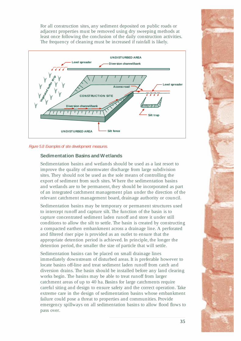
For all construction sites, any sediment deposited on public roads or adjacent properties must be removed using dry sweeping methods at least once following the conclusion of the daily construction activities. The frequency of cleaning must be increased if rainfall is likely.
UNDISTURBED AREA
Vege
tate
d bu
ffer
stri
p
Level spreader Diversion channel/bank
Silt trap
Silt fence UNDISTURBED AREA
Level spreader
CONSTRUCTION SITE
Access road
Diversion channel/bank
Figure 5.8 Examples of site development measures.
Sedimentation Basins and Wetlands
Sedimentation basins and wetlands should be used as a last resort to improve the quality of stormwater discharge from large subdivision sites. They should not be used as the sole means of controlling the export of sediment from such sites. Where the sedimentation basins and wetlands are to be permanent, they should be incorporated as part of an integrated catchment management plan under the direction of the relevant catchment management board, drainage authority or council.
Sedimentation basins may be temporary or permanent structures used to intercept runoff and capture silt. The function of the basin is to capture concentrated sediment laden runoff and store it under still conditions to allow the silt to settle. The basin is created by constructing a compacted earthen embankment across a drainage line. A perforated and filtered riser pipe is provided as an outlet to ensure that the appropriate detention period is achieved. In principle, the longer the detention period, the smaller the size of particle that will settle.
Sedimentation basins can be placed on small drainage lines immediately downstream of disturbed areas. It is preferable however to locate basins off-line and treat sediment laden runoff from catch and diversion drains. The basin should be installed before any land clearing works begin. The basins may be able to treat runoff from larger catchment areas of up to 40 ha. Basins for large catchments require careful siting and design to ensure safety and the correct operation. Take extreme care in the design of sedimentation basins whose embankment failure could pose a threat to properties and communities. Provide emergency spillways on all sedimentation basins to allow flood flows to pass over.
35
Sedimentation basins usually do not effectively remove fine silt and clay sized particles because of the length of time they take to settle. Sedimentation efficiency can be improved if emergent aquatic vegetation is established within the basin which, if kept permanently wet, will provide some of the advantages associated with wetlands.
Artificial wetlands have the added benefits of:
• additional pollutant removal mechanisms, particularly soluble impurities, and plants acting as physical barriers to sediment movement
• enhanced aesthetic value
• creation of more diverse habitats for wildlife
• being a significant education resource for schools and communities on the importance of stormwater pollution control.
Artificial wetlands must be designed and managed in accordance with the requirements and objectives of the relevant catchment management board, drainage authority or council. Consider such factors as:
• mosquito control, preferably by natural methods based on providing a diverse habitat for mosquito predators and the creation of wave action
• maintenance requirements, particularly with regard to the desilting of the wetlands
• the fate of any sediments removed from the wetlands, particularly with possible metal contamination
• the need for a harvesting schedule of wetland vegetation to prevent the release of captured nutrients during the plant die-off period.
Natural wetlands must not be used for the treatment of stormwater pollution.
5.4 Soil Erosion and Drainage Management Plan
General
For any site development, the planning and implementation of a soil erosion and drainage management strategy should be integrated into the initial development plan.
A SEDMP must be prepared:
• where there is a high risk of sediment pollution to adjoining lands or receiving waters; or
• if the total area to be disturbed, or left disturbed, at any one time exceeds 0.5 ha.
A SEDMP is not required if the risk of the development activities affecting stormwater quality are minimized, for example, if a site is developed at a depth significantly below street level such as multi-story buildings.
36
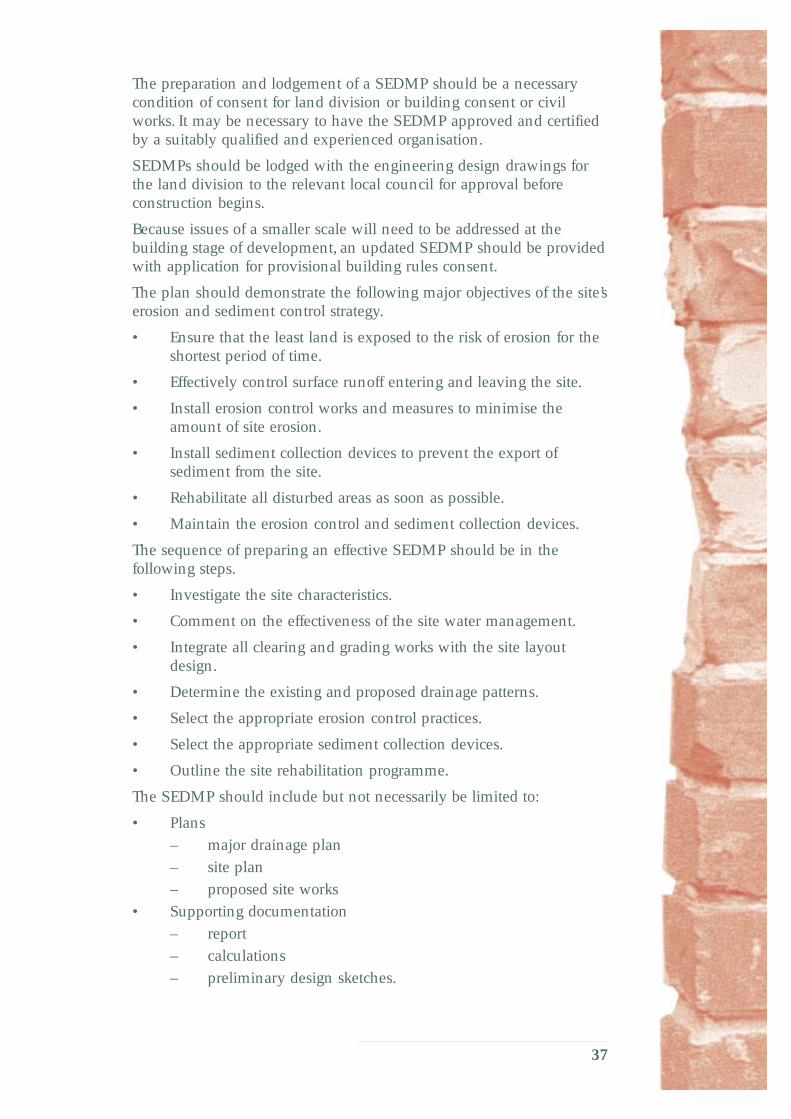
The preparation and lodgement of a SEDMP should be a necessary condition of consent for land division or building consent or civil works. It may be necessary to have the SEDMP approved and certified by a suitably qualified and experienced organisation.
SEDMPs should be lodged with the engineering design drawings for the land division to the relevant local council for approval before construction begins.
Because issues of a smaller scale will need to be addressed at the building stage of development, an updated SEDMP should be provided with application for provisional building rules consent.
The plan should demonstrate the following major objectives of the site’s erosion and sediment control strategy.
• Ensure that the least land is exposed to the risk of erosion for the shortest period of time.
• Effectively control surface runoff entering and leaving the site.
• Install erosion control works and measures to minimise the amount of site erosion.
• Install sediment collection devices to prevent the export of sediment from the site.
• Rehabilitate all disturbed areas as soon as possible.
• Maintain the erosion control and sediment collection devices.
The sequence of preparing an effective SEDMP should be in the following steps.
• Investigate the site characteristics.
• Comment on the effectiveness of the site water management.
• Integrate all clearing and grading works with the site layout design.
• Determine the existing and proposed drainage patterns.
• Select the appropriate erosion control practices.
• Select the appropriate sediment collection devices.
• Outline the site rehabilitation programme.
The SEDMP should include but not necessarily be limited to:
• Plans
– major drainage plan
– site plan
– proposed site works
• Supporting documentation
– report
– calculations
– preliminary design sketches.
37
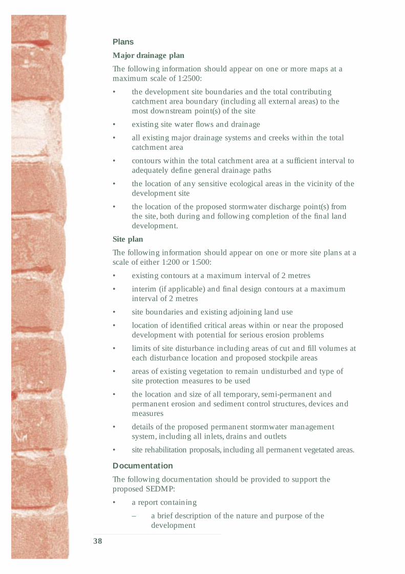
Plans
Major drainage plan
The following information should appear on one or more maps at a maximum scale of 1:2500:
• the development site boundaries and the total contributing catchment area boundary (including all external areas) to the most downstream point(s) of the site
• existing site water flows and drainage
• all existing major drainage systems and creeks within the total catchment area
• contours within the total catchment area at a sufficient interval to adequately define general drainage paths
• the location of any sensitive ecological areas in the vicinity of the development site
• the location of the proposed stormwater discharge point(s) from the site, both during and following completion of the final land development.
Site plan
The following information should appear on one or more site plans at a scale of either 1:200 or 1:500:
• existing contours at a maximum interval of 2 metres
• interim (if applicable) and final design contours at a maximum interval of 2 metres
• site boundaries and existing adjoining land use
• location of identified critical areas within or near the proposed development with potential for serious erosion problems
• limits of site disturbance including areas of cut and fill volumes at each disturbance location and proposed stockpile areas
• areas of existing vegetation to remain undisturbed and type of site protection measures to be used
• the location and size of all temporary, semi-permanent and permanent erosion and sediment control structures, devices and measures
• details of the proposed permanent stormwater management system, including all inlets, drains and outlets
• site rehabilitation proposals, including all permanent vegetated areas.
Documentation
The following documentation should be provided to support the proposed SEDMP:
• a report containing
– a brief description of the nature and purpose of the development
38

– a description of the existing site topography, soil erodibility, vegetation and drainage pattern(s)
– a description of neighbouring areas, such as creeks, lakes, reserves and existing development that may be affected by the land disturbance
– a statement regarding the impact the proposal will have on the existing drainage pattern within and adjacent to the development site
– a description of the methods adopted to control erosion and sediment during construction
– a brief description of how the site will be stabilised after construction is completed
– a construction schedule including the
• phasing of land disturbance works
• staging of the rehabilitation of the disturbed areas
• implementation of the temporary or permanent erosion and sediment control structures and strategy
– a maintenance schedule of regular inspections, cleaning and repairs of all erosion and sediment control structures
• calculations supporting the selection of the size of any temporary or permanent erosion and sediment control structures; they should be of sufficient detail to enable the preliminary sizing of all structures, such as the silt storage capacity of a sediment trap
• preliminary drawings of all major temporary or permanent structures such as sedimentation basins that are not standard structures or devices.
Detail
The amount of detail required to be prepared for a SEDMP will vary between projects. Suitable risk management techniques should be used to determine the appropriate recurrence interval standard for the works required to comply with this code. In essence, an assessment should be conducted that relates the exposure risk created by the activity to the likely environmental harm or damage.
Factors that should be considered as part of this risk management assessment include but are not necessarily limited to:
• the size and nature of the external contributing catchment
• the scale of the project
• the estimated duration of the works involved with the project
• susceptibility of the exposed surfaces to be eroded
• ecological sensitivity of the surrounding environment
• consequences of the failure of any of the SEDMP works
39

SF
CB
• ability to instigate effective emergency clean up procedures in the event of a failure
• season
• likelihood of short term rainfall
• climate
• natural vegetation growth.
Standard Symbols
It is suggested that the standard symbols shown in figure 5.9 be adopted for use in the preparation of all SEDMPs.
SFSF
CBCB
SB Sedimentation basin
ST
Plant and equipment compound
SSP Soil stock pile
Site boundary
Limit of clearing and gradingXXXX HB HB
Level spreader
Sediment trap
Silt fence
Vegetated filter strip
Hay bale barrier
Stabilised waterway
Temporary construction exit
Catchment boundary
Diversion/catch drain
Protective fence
Figure 5.9 SEDMP standard symbols.
Examples
The two examples of site plans illustrated are for:
• single residential allotment development (see figure 5.10)
• residential subdivision roadworks formation (see figure 5.11).
LEGEND
SF SF SF Silt fence
Stormwater drain
101.5101.0
100.5
100.0
SF
SF SFSF
Diversion/catch drain
Site boundary
HOUSE LOCATION
Figure 5.10 Single residential development example.
40
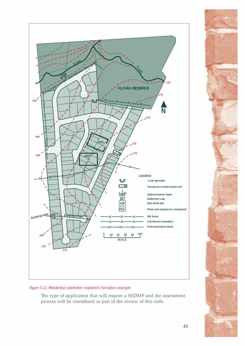
SSP
PEC
SSP
PEC
ST
SB
SB
Creek
Creek
Existing Inlet Existing Drain
LEGEND
Sedimentation basin
Soil stock pile
Plant and equipment compound
N
SCALE
0 20 40 60 80 100
170
172
174
176
178
172 170
168
168
166
164
ST
SF SF SF SF
SF
CBCBCB
CB
CBCBCB
CBCB
SFSFSF
CBCBCB
FLORA RESERVE
Level spreader
Temporary construction exit
Sediment trap
Silt fence
Catchment boundary
Diversion/catch drain
Figure 5.11 Residential subdivision roadworks formation example.
The type of application that will require a SEDMP and the assessment process will be considered as part of the review of this code.
41

6 HOUSING, INCLUDING HOME IMPROVEMENTS This section is for residential (class 1) buildings and class 10 structures as defined by the building code of Australia and must be read in conjunction with chapters 1,2 and 5.4.
6.1 Soil Erosion and Drainage Management Plan The SEDMP should be lodged with the application for Provisional Building Rules Consent.
A sufficient SEDMP should consist of a site drainage plan (as required by the Building Rules), which includes such site drainage and erosion control measures set out in section 6 as are necessary to achieve the objectives of this code.
Site Drainage Plan
All of the following information should appear on the site drainage plan at a scale of either 1:200 or 1:500:
• locality plan and the boundaries and dimensions of the site and any relevant easements
• existing contours and final design contours including location of cut and fill banks
• final overland flow drainage path
• general soil description if available
• the positions and dimensions of any proposed building and its relationship to the boundaries of the site
• proposed stockpile areas
• the location type and size of all temporary, semi-permanent and permanent erosion and sediment control structures, devices and measures
• installation sequence and maintenance requirements of control measures
• the approximate north point.
Standard symbols
For a list of standard symbols see figure 5.9.
Examples of site drainage plan
Two examples of site plans are illustrated here. These are for:
• single residential allotment developments with a slight fall (see figure 6.1)
• single residential allotment developments with a steep fall (see figure 6.2).
42

LEGEND
Stormwater drain
101.5101.0
100.5
100.0
SFSFSF
SF
SF SFSF
SB
SSP
Cut
Fill
Silt fence
Diversion/catch drain
Site boundary
HOUSE LOCATION
Hardstand driveway
Figure 6.1 Single residential development example – slight fall.
101.0
100.5
100.0
HOUSE LOCATION
SF 99.5 Cut
SF SB Fill
SF
SBSSP
99.0
SFSF
SFSF
SF SF SF
SF
LEGEND
SF SF SF Silt fence
Stormwater drain
Diversion/catch drain
Site boundary
Hardstand driveway
Figure 6.2 Single residential development example – steep fall.
43

Zero lot line housing and small lot housing
Off-site sediment control measures are sometimes needed as individual lots may be too small to install and maintain control measures on-site during the construction sequence.
If this is the case, off-site sediment control measures will need to be determined on an individual basis, in conjunction with the relevant off-site land owner. In any case, the guiding principles of this code must be adhered to.
Soil and Sediment Control Structures
This section gives a brief description of soil erosion and sediment control structures to be used on Class 1a and 10a construction sites.
Silt fences
Silt fences are a temporary sediment control measure, which are constructed from geotextile filter fabric, to intercept sediment laden runoff and retain sediment. The main purpose of a silt fence is to reduce runoff velocities and cause the deposition of silt.
DISTURBED AREA UNDISTURBED AREA
0.5–0.6 m
set into posts or 1.5 kg/m steel posts
filter strip
Geofabric and wire mesh buried 0.2 m into ground. On rocky ground,concrete plinth or sufficiently weighted down
Flow direction
Provide stakes at 2.0 m max spacing' driven 0.5–0.7 m into ground Stakes to be 0.1 m diameter timber
Fasten wire mesh to stakes with heavy duty wire staples.
Fix Geofabric to wire mesh joints to have min 0.3 m overlap and either sewn or attached stakes
Vegetated
Figure 6.3 Silt fence installation method.
Commercially available silt fences are also available, offering complete prefabricated systems and greater ultra-violet stability.
Hardstand driveway (unloading area)
Where there is risk that delivery trucks etc will track soil and sediment from the site on to the roadway, the provision of a suitable access driveway should be considered.
A ‘hardstand’ driveway or loading area is one method which could be provided for vehicles (such as delivery trucks) to ensure that spoil is not removed from the site.
44

For all construction sites, any sediment deposited on public roads or adjacent properties must be removed at least once following the conclusion of the daily construction activities. The frequency of cleaning must be increased if rainfall is likely.
Loads that may be subject to loss through wind erosion or accidental spillage must be totally and securely covered or sealed. Loose material should be cleaned from trucks before they leave the site.
When loading and unloading, prevent spillage of materials on to the road. Any accidental spills must cleaned up immediately so as to prevent the material from entering the stormwater system.
Berm
Existin
g road
way
Runoff from pad ence
Constructio
n site
0.3
min
imum
directed to silt f
0.15
min
imum
Quarry rubble or PM21 gravel
50–75 mm gravel
Figure 6.4 Hardstand driveway.
For building sites with only small areas of disturbed soil that are not accessible to construction traffic, temporary construction exits may not be required.
Sedimentation basin
A sedimentation basin is an earth mound bunded (contained) area for collecting small scale runoff from an individual building site and used for the soakage and collection of washing out water and sediments from construction activities and trades.
Diversion channel/bank
An earth mound or shallow earth drain collects runoff and diverts flow to a silt fence or sedimentation basin (see figure 6.5).
45

UNDISTURBED AREA
Und
istu
rbed
Are
a
sediment basin per section 6.2.4
Diversion channel/bank
Silt fence UNDISTURBED AREA
Silt trap
CONSTRUCTION SITE
Diversion channel
Diversion channel/bank
EXAMPLES OF SITE DEVELOPMENT MEASURES
Figure 6.5 Examples of use of diversion channel/bank.
6.2 Construction Works—Operational Controls Soil erosion and the generation of sediment during construction activities cannot be entirely prevented. Sound project planning can reduce the potential for erosion but control measures will always be necessary to reduce the impact of the erosion both on-site and off-site.
Operational construction control measures described in this section should be combined with the soil erosion and sediment control and site drainage measures and plans described in section 6.1.
Building Construction Works
All building construction works must be conducted in such a manner so as to minimise the entry of pollutants into the stormwater system. This includes, but is not necessarily limited to, the following building activities and trades. It is hoped that builders will create the circumstances necessary for tradespersons to be able to meet the requirements of this Code of Practice, for instance by clearly designating contained waste areas on site.
Minimise disturbance of the site
• Minimise disturbance of the site when cutting and filling and excavating the building platform. Preserve as much grassed area as possible as these areas filter much of the sediment from stormwater runoff before it reaches the drainage system.
Hard waste
• All hard waste must be stored on-site in such a manner so as to prevent any materials from entering the stormwater system either by wind or water action.
46

• Small items should be contained in covered bins.
• Disposal of the waste should be by recycling or to a waste depot licensed to receive that waste.
Concrete works
• Where possible, all residues and wastes generated by concrete works must be prevented from entering the stormwater system.
• On-site mixing of concrete, either by hand or by mechanical means, should be carried out in a designated area of the site which is capable of containing all excess water, residues and waste.
• Where site conditions require the use of concrete pumps from public roadways, temporary bunds must be provided across all downslope gutters to trap any spilt material. All spilt material must be removed from the roadway and gutter prior to the removal of the temporary bunds.
• Concrete mix trucks, pumps and equipment must not be washed down in roadways, footpaths or reserves. These vehicles and equipment should be washed down either within a designated contained area within the site or at a suitably designed and operated depot washdown facility.
• Waste concrete slurry should be allowed to dry and either be disposed of on-site or taken to a licensed waste depot.
Brick works and brick cutting
• Mortar must not be mixed in gutters or any other location, which will drain to the stormwater system.
• All wastewater from brick cutting activities must be prevented from entering the stormwater system.
• Brick cutting activities that generate surplus wastewater should not be carried out on public roads, footpaths or reserves.
• Surplus wastewater from brick cutting activities should be either recycled, disposed to sewer (with SA Water Industrial Wastes Section approval) or discharged into a contained area for drying by soakage.
Painting
• Paint waste and wash waters must not be discharged to the stormwater system.
• Water-based paint cleaning water should be disposed of to sewer or diverted into a contained area lined with newspaper on-site. When it is dry, place the newspaper with paint residue in a solid waste bin.
• Oil-based clean up material should be filtered for reuse of the solvent or taken to a waste depot that is licensed to accept these wastes. Place the paint residue after filtering in a solid waste bin.
• Unused paint should be kept in the tin or other sealed container and disposed of to a waste depot licensed to receive this waste.
47

Plastering
• Plastering waste and wash waters must not be discharged to the stormwater system.
• All residues and wastes from plastering activities should be allowed to dry within a designated contained area of the site. Solid waste should be disposed of either on-site or taken to a licensed waste depot.
• Alternatively, solid wastes from plastering activities such as calcium sulphate may be used as a clay modifier in gardens.
Cleaning
• Paint stripping waste, roof cleaning waste and other general building cleaning wastes must not be allowed to enter the stormwater system. With the exception of certain hazardous materials (eg lead/caustic paint scrapings), these wastes should be discharged either into a contained area on the site for soakage or to sewer (with SA Water Industrial Wastes Section approval).
Refer to High Pressure Water Blasting Code of Practice available from the
Environment Protection Agency.
Plumbing
• Site services should be installed in accordance with AS/NZS 3500:1998 3.2 within a reasonable time to minimise runoff to the stormwater system.
Airconditioner installations and cooling tower wastewater
• Evaporative airconditioners must be installed in such a manner so that saline water from the cooler dump valve systems and non-dump valve systems are not allowed to enter the stormwater system.
• The saline wastewater from airconditioner dump valve systems and cooling towers should be directed to sewer or to a suitable (saline tolerant) garden area or rainwater tank (if not used for drinking).
Note: Wastewater should not be allowed to exit the site on to a neighbouring
property as this may cause environmental nuisance.
Soil and materials stockpiles
• Stockpiles of soil and building materials must be maintained within the area contained by the silt fence.
• Stockpiles, for example soil/cement, should be covered by a tarpaulin at the end of each day if rain or excessive wind is likely.
• Site stormwater drainage should be directed away from or around the stockpiles.
Roof stormwater
• The stormwater disposal system should be directly connected to the street stormwater system or rainwater tank as soon as practicable after roof completion/downpipe installation.
48

Delivery of building materials
• Delivery vehicles should enter and exit the site on the access driveway or hardstand driveway where provided, to minimise the potential for tracking of mud and soils on to roads. See subsection on Hardstand Driveway, in section 6.1, for further details on unloading vehicles.
Fuel or chemical use
• Where fuels or chemicals are used or temporarily stored on-site, due care must be taken to ensure they are securely contained, so they do not enter the stormwater or groundwater system.
Dust Emissions During Excavations
Dust can cause significant nuisance to nearby residents and can cause pollution of stormwater. Dust emissions from the site should be controlled so as to minimise any adverse effect on the amenity value of an area.
49

BIBL IOGRAPHYErosion Control and Sediment Collection Manuals
Australian and New Zealand Environment and Conservation Council(ANZECC). 1992 National Water Quality Management Strategy.Australian Water Quality Guidelines for Fresh and Marine Waters.
BC Tonkin & Associates, and Eco Management Services. 1992. Guideline manual — Urban stormwater runoff quality control measures for the Mount Lofty Ranges watershed. Engineering and Water Supply Department.
Carter, J. 1995. Watercourse processes: A guide for watercourse managers in the Mount Lofty Ranges. Water Resources Group, Department of Environment and Natural Resources.
Carter, J and Collingham, E. Guide to control measures for small watercourses in the Mt Lofty Ranges. Available from Catchment Resource Centre, 5C Cameron Street, Mount Barker, 5251, Phone: (08) 8391 7500, Fax: (08) 8391 7524
Emergency response to a leakage or spillage of hazardous material during transport, storage or handling. The role and responsibilities of the emergency services and other government agencies. 1997. Government of South Australia.
Environment Protection Authority. 1997. Stormwater PollutionPrevention/General Code of Practice for the Community.
Environment Protection Authority. 1997. Stormwater Pollution Prevention/General Code of Practice for Local, State and Federal Government.
Hunt, JS (Ed). 1992. Urban erosion and sediment control. Department of Conservation and Land Management.
Morse McVey & Associates. Soil and water management for urban development. NSW Department of Housing.
Peterson SM and Bately GE. 1993. The fate of pesticides in Australian Rivers. Chemistry in Australia, Aquatic and Environmental Chemistry Supplement, August 1993.
Scott & Furphy Pty Ltd. 1988. Design manual for urban erosion and sediment control. National Capital Development Commission.
State Pollution Control Commission. 1989. Pollution control manual for urban stormwater.
Catchment Resource Centre Waterwise InformationPamphlets:
• Revegetation of watercourses
• Watercourse management
• Exotic trees along watercourses
50

ACKNOWLEDGMENTS
This Code of Practice has been prepared in consultation with the following industry reference group.
Their assistance and input is gratefully acknowledged.
Building and Construction Industry Reference Group
Mr Bill Beattie Master Builders Association of SA Incorporated
Mr Colin Best Bardavcol Pty Ltd
Mr Glen Blackmore Civil Contractors Federation
Mr Allan Gilbert Allan Gilbert and Associates Pty Ltd
Mr Derek Stapleton CFMEU Construction and General
Mr Ian Sutherland Housing Industry Association
Ms Carolyn Wigg Planning S.A.
The City of Tea Tree Gully for permission to include material from their Stormwater Management Bulletin.
B C Tonkin and Associates, Adelaide for permission to include material from the Mount Lofty Ranges Watershed Urban Stormwater Guideline Manual.
51

APPENDIX 1 RELEVANT LEGISLATION
This appendix contains additional information about legislative controls that may apply when considering the objectives of this Code of Practice.
Environment Protection Act 1993
Codes of Practice and Environment Protection Policies
Codes of Practice are the vehicles currently being used by the EPA to achieve improved stormwater quality. The purpose of the codes is to provide guidelines on how to prevent pollution from leaving sites where the pollution originates, by the use of long term planning, modification of practices and treatment at source where appropriate.
Following the formation of the Water Quality EPP, agencies will have a period of time to implement actions to adhere to the mandatory provisions of the EPP, on condition that the agencies demonstrate that they are making appropriate changes towards meeting the provisions of the EPP.
Authorised Officers
The Act allows for the following persons to be appointed as authorised officers:
• those appointed by the Authority (with the approval of the Minister)
• all members of the police force
• a council employee or officer as appointed by the relevant council after consultation with the Authority (powers of council appointed authorised officers may be limited by regulation).
Fully authorised officers are empowered to:
• require compliance with the mandatory provisions of an EPP
• enter and inspect places or vehicles including, on the obtaining of a warrant from a justice, breaking into a place or vehicle
• require documents or information to be produced and to take copies of such documents or information
• take samples for analysis, examine or test plant, equipment or vehicles
• take photographs, films, audio, video and other recordings
• seize material evidence
• require a person to provide their name and address and to answer questions.
52

Water Resources Act 1997 The Water Resources Act 1997 allows for the proclamation by the Governor of a catchment area to be administered by a catchment water management board. The board is charged with preparing a catchment water management plan for its catchment area, which includes water quality objectives of:
• removing pollutants from watercourses
• providing support for activities which will improve the quality of catchment water
• educating the public in relation to the management of the catchment.
This stormwater pollution control Code of Practice has been designed to prevent the entry of pollutants to watercourses by proposing strategies and works to control the generation of the pollutants at their source.
Local Government Act 1934 The Local Government Act 1934 provides councils with certain obligations and powers for the protection of watercourses. Although principally targeting the issue of flood control, the relevant sections of the Local Government Act could be interpreted to include issues related to the source control of stormwater pollutants. Under these wider interpretations, the Code of Practice is intended to be in agreement with the Local Government Act.
Any person who wishes to alter a watercourse should consult directly with the relevant council.
Specific sections of the Local Government Act relate to the source control of stormwater pollutants:
Section 634
specifies that councils are responsible for the protection of all watercourses within their areas (except where the watercourses are proclaimed under the Water Resources Act 1997).
Section 635
requires council authorisation for persons to deposit anything in a watercourse, obstruct, alter the course or interfere with the bed or banks of a watercourse.
Section 636
allows councils to require the removal of obstructions, the making good of damage, or maintenance of a watercourse, which passes through privately owned land.
Section 637
gives councils the power to carry out works to remove obstructions, make good damage and otherwise maintain a watercourse in good condition.
53

Section 748a
gives councils the power to fine any person depositing litter, refuse or waste matter in a street, road or public place.
Various penalties and appeal procedures are included in some of these provisions.
Sewerage Act 1929 The Sewerage Act 1929, and its associated Regulations specify allowable discharges to sewer. Telephone the SA Water Industrial Wastes Section on (08) 8207 1350 to obtain further information about the current Trade Wastes licensing conditions.
Soil Conservation and Landcare Act 1989 The central requirement of the Soil Conservation and Landcare Act 1989 is:
that it is the duty of an owner of land to take all reasonable steps to prevent degradation of the land
where ‘land’ is described in the Act as ‘its soil, vegetation and water’, and ‘degradation’ of land means a decline in the quality of soil, vegetation, water and other natural resources of the land, resulting from overgrazing, excessive tillage, mineral extraction, development of towns, disposal of wastes, road construction, failure to control plant and animal pest or any other human activity on the land.
The State has at present 27 soil districts of varying size, each with its own district plan. These districts cover all of the State with the exception of all Aboriginal lands and parts of metropolitan Adelaide. Each district plan is administered by its own soil conservation board, appointed by the Minister of Primary Industries. In the absence of a defined district or board, the designated soil conservator is the administrator.
Soil conservation boards and the soil conservator are empowered by the Act to exercise its powers, mainly through the issuing of Soil Conservation Orders.
As a rule, few of these orders are issued because the board’s primary role is education and negotiation to address problems and effect community change.
State and Federal Government agencies should consult with the relevant soil conservation board before undertaking major works.
Development Act 1993 Development plans, as defined in division 2 of the Development Act 1993, may be amended to include the provisions of an EPP under section 29(1)(b) and Regulation 14(b). Regardless of the incorporation of EPPs or aspects of EPPs into development plans, any development which requires authorisation under the Development Act will also require compliance with all EPPs in force at the time.
54

It is also important to note that the procedures in any EPP apply also in circumstances in which any prior non-complying use of land is expanded.
Development plans currently contain both regional and local objectives and principles of development control (some of which will have stormwater implications) that authorities have to have regard to when assessing development applications. The stormwater related issues can be addressed by the design of development proposals approved under the Development Act and by conditions of consent on application.
Other Legislation The following legislation requirements may also be relevant in certain situations and should be referred to as required.
• Pollution of Waters by Oil and Noxious Substances Act 1987 (section 26) prohibits the discharge of oil or any oily mixture from a vehicle or apparatus (eg pipeline, structure on land, oil storage receptacle) into State waters.
• Petroleum Products Regulation Act 1995 (sections 25 and 26) requires a general environmental duty and a duty to prevent the risk of significant environmental harm and to ensure the plant is in a safe condition and that it does not give rise to the risk of significant environmental harm whether in use or not in use.
• Dangerous Substances Act 1979 regulates the keeping, handling, conveyance and use of dangerous substances and provides directives on how the substances must be kept (eg bunding for flammable, toxic and corrosive substances), calling up Australian Standard AS 1940–1993 The Storage and Handling of Flammable and Combustible Liquids, as the compliance document. In setting out requirements, AS 1940 also addresses the matter of preventing a spill or leak from entering the sewerage and water systems and contaminating soil.
• Environment Protection (Impact of Proposals) Act 1974 binds Commonwealth bodies to fully examine and take into account matters that affect the environment.
• Australian Heritage Commission Act 1975 applies to those places in the natural and cultural environment that have special significance.
• Endangered Species Protection Act 1992.
• National Parks and Wildlife Conservation Act 1975.
• Aboriginal and Torres Strait Islander Heritage Protection Act 1984.
55

INDEXAirconditioner installations 11, 48
Audit, site 12
Brick works and brick cutting 10, 47
Cleaning 11, 14, 48
Concrete works 10, 47
Construction 7, 46
– building 9, 46
– general criteria 8
– minor 11–12
– planning and practice 21
– road and rail 8
Demolition 18
Disturbed areas, stabilisation andrehabilitation 24
Diversion channel/bank 35, 45–46
Drainage design 18–19, 34, 38, 42
Drains
– catch or diversion 26
Dust 24–25, 49
Emergency response 17, 18
Enforcement under the Act 5–6
Exit, temporary construction 23, 34–35
Fuel dispensing areas 13
General Environmental Duty 5
Hardstand driveway 44, 49
Hay bale barriers 23, 29–30
Land development 20, 21
Level spreaders 27
Maintenance work 11–12
Painting 10, 47
Parking areas 14
Pesticides 15–17
Plans (see also Soil erosion and drainagemanagement plans)
– major drainage 38
– site 38
– site drainage 42–43
Plastering 11, 48
Revegetation 27
Sediment collection structures 12, 22–24, 29–37, 44–46
– off-site 44
Sediment traps 23, 33
Sedimentation basins 23–24, 35–36, 45
Services installation 9
Sewage 2
Silt fences 23, 30–31, 44
Soil erosion and drainage managementplans (SEDMP) 4, 7, 36–41, 42–46
– detail 39
– documentation 39
– examples 40–41
Soil erosion control 7–8, 20–22, 26–41
Spills, clean-up procedures 17
Standards, Australian 6
Stockpiles 8, 9, 12, 21, 30, 48
Storage, loading and unloading areas 13,14, 44–45, 49
Stormwater 3, 18–19
– connection 48
– inlet pit traps 31–32
Symbols, standard 40, 42
Termite protection 11
Transportation 18
Uncovered work areas 13
Vegetation
– buffers and filter strips 14, 23, 24, 33–34
– for erosion control 24, 27
Vehicle, plant and equipment cleaning
areas 14
Waste disposal 12–13
Waste, hard 9, 46–47
– disposal, landfill and borrow pit sites 14–15
Water, waste or wash 10, 11, 13, 14, 34, 47,
48
Watercourses 18–19, 24–25
– and pesticides 16
Waterways, stabilised 28
Wetlands 24, 35–36
Workshops 13