Embed Size (px)
Citation preview

Trimmer
INSTRUCTIONAND PARTS
MANUAL
Trimmer

2
Trimmer
Introduction ....................................................... 3
Specifications ..................................................... 3
Safety ................................................................. 4, 5
Installation .......................................................... 6-8
Setup .................................................................. 9
Control Panel ..................................................... 10
Opperation ......................................................... 11, 12
Maintenance ....................................................... 13
Adjustments ....................................................... 14
Fuses Access ...................................................... 15
Preventive Maintenance ..................................... 15
Knife Removal & Installation ......................... 16-19
Clearing A Trimming Jam ............................... 19
Knife Care Tips ................................................. 20
Notes .................................................................. 21
Trouble Shooting ............................................... 22-25
Exploded Drawings & Parts Lists .................... 26-40
Motor Wiring ..................................................... 41
Wiring Diagram ................................................. 42
Electrical Schematic ........................................... 43
CONTENTS

3
TRIMMER SPECIFICATIONS
Unit Weight: 236 Pounds
Speed: Up to 2,400 booklets per hour (115Vac machine)
Capacity: Minimum
4.00" cut width x 4.13" to fold (trim length)
2 sheets 20# bond thickness
Maximum
12.71" cut width x 9.00" to fold (trim length)
50 sheets 20# bond thickness (0.20")
.625" maximum material trim
Booklets: 4.25" x 5.5", 5.5" x 8.5", 8.5" x 11", 4.75" x 4.75 "CD", & metric sizes
(All booklets with or without trim stock on one or three sides)
Output: Indexing conveyor
Footprint: 16.50" x 18.38"
Dimensions: Height 27.38" Width 26.42" Length without discharge table 25.90"
Length with fully extended discharge table 48.44"
Modes: Trim or No-trim
Electrical: Standard outlet - 115 Volts, 60 Hz, 6 Amps (1/4 HP)
Optional: 230Vac, 50 Hz, 3 Amps
INTRODUCTION
MBM Corporation is proud to introduce another addition to its complete line of equipment for bookletmaking.Now you have the ability to trim books in-line! This combination offers you reliability and versatility thatimproves production and reduces downtime.
Trimmer Features:
In-line face trimming of bookletsJam detectionElectrical interface for communication with StitchFold Bookletmaking SystemSafety interlockSee-through top cover

4
TrimmerSAFETY
A. Top Cover: Blocks access to mechanism thatdrives the trimming knife and conveyor belts.An electrical interlock keeps the machineturned off unless this guard is closed. Do notstick your fingers under the top guard!
B. Front Upper Cover: Blocks access to the trim-ming knives and the mechanism that drives theupper trimming knife.
C. Infeed Table Bottom Cover: Blocks access toinfeed conveyor belts.
D. Front Lower Cover: Blocks access to danger-ous electric voltage and mechanisms that canpinch or cut. Be sure to disconnect electricalpower before removing this cover.
E. Right Side Cover: Blocks access to low volt-age connections and mechanisms that can pinchor cut. Do not stick your fingers beyond thiscover!
F. Rear Upper Cover: Blocks access to danger-ous electric voltage and control circuit con-nections. Be sure to disconnect electricalpower before removing this cover.
G. Rear Lower Cover: Blocks access to low volt-age connections and mechanisms that can pinchor cut. Do not stick your fingers beyond thiscover!
H. Left Side Cover: Blocks access to low volt-age connections and mechanisms that can pinchor cut. Do not stick your fingers beyond thiscover!
SAFETY GUARDS (figs 1 & 2)
1. Make sure electrical power is turned off be-fore performing any adjustment or mainte-nance.
2. Keep hands, hair, tools, and clothing clear oftrimming area.
3. Become familiar with the moving componentsof your machine. Keep fingers away fromareas that could pinch or cut.
4. BE EXTREMELY CAREFUL when changingthe cutter knife. Severe lacerations or dis-memberment could result from careless han-dling procedures.
5. NEVER REACH UNDER THE KNIFE Severelacerations or dismemberment could result.
6. NEVER OPERATE THE TRIMMER WITHOUTTHE B2000 BOOKLETMAKER AND SAFETYINTERLOCK SYSTEM.
6. A well maintained machine is a safer machine.Clean and lubricate the machine at regular in-tervals. Check machine daily for broken orworn parts. Replace as necessary. DO NOTattempt to operate the machine if a part is bro-ken.
7. See "SAFETY GUARDS" below! If you areunsure how to safely operate your trimmer, contactyour Service Representative.
SAFETY PRECAUTIONS AND PROCEDURES
DANGER
KEEP HANDS CLEAR OF TRIMMING AREA AND ANY MOVING PARTS!NEVER OPERATE MACHINE WITHOUT ALL GUARDS IN PLACE!

5
SAFETY GUARDS
A. Top Cover
B Front UpperCover
D. Front LowerCover
H. Left SideCover
E. Right SideCover
F. Rear UpperCover
G. Rear LowerCover
C. Infeed TableB o t t o mCover
(Fig 1)
(Fig 2)

6
TrimmerINSTALLATION
BEFORE UNCRATING:
Examine the crate for visible damage. If the crateis damaged, the machine might be damaged. Notifythe carrier who delivered the machine.
UNCRATING THE MACHINE:
Carefully remove the machine from its container.Lift the machine by grasping its strong framework.Tugging on cables, covers, or other delicate com-ponents could cause damage.
Examine the machine for damages incurred duringshipping. Do not install a damaged machine.Notify the carrier immediately, and be sure to geta signed copy of the Carrier Inspector's Report ofthe damage incurred. Your service representativewill assist you in determining the cost of repairs.
ELECTRICAL POWER:
The power cord can be plugged into any 115V, 60Hz, 1 Phase, 15 Amp circuit. The machine drawsless than 6 amps.
SAFETY INTERLOCK SYSTEM:
Connect the safety interlock system as follows:
1. Remove the back cover (see fig 3) from theBookletmaker.
2. Put the bolt through the washer of the safetykey assembly and screw the bolt half way intothe back cover of the Bookletmaker (see fig 4).
3. Install and securely tighten the nut onto the endof the bolt (see fig 5). The bolt must only beremoveable by removing the nut first.
4. Install the back cover onto the Bookletmaker(see fig 5).
WARNINGNEVER OPERATE THE TRIMMER
WITHOUT THE B2000BOOKLETMAKER AND SAFETY
INTERLOCK SYSTEM CONNECTED.
(Fig 3)
(Fig 4)
(Fig 5)
Back Coverof Bookletmaker
CB145A NutCB379 Screw
RTM1327A Key
7
TRIMMER TO BOOKLETMAKER CONNEC-TIONS:
1. Adjust the height of the trimmer so that the topof the trimmer infeed table is about even withthe middle of the BookletMakers top dischargeroller (see fig 6).
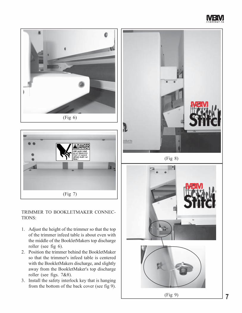
2. Position the trimmer behind the BookletMakerso that the trimmer's infeed table is centeredwith the BookletMakers discharge, and slightlyaway from the BookletMaker's top dischargeroller (see figs. 7&8).
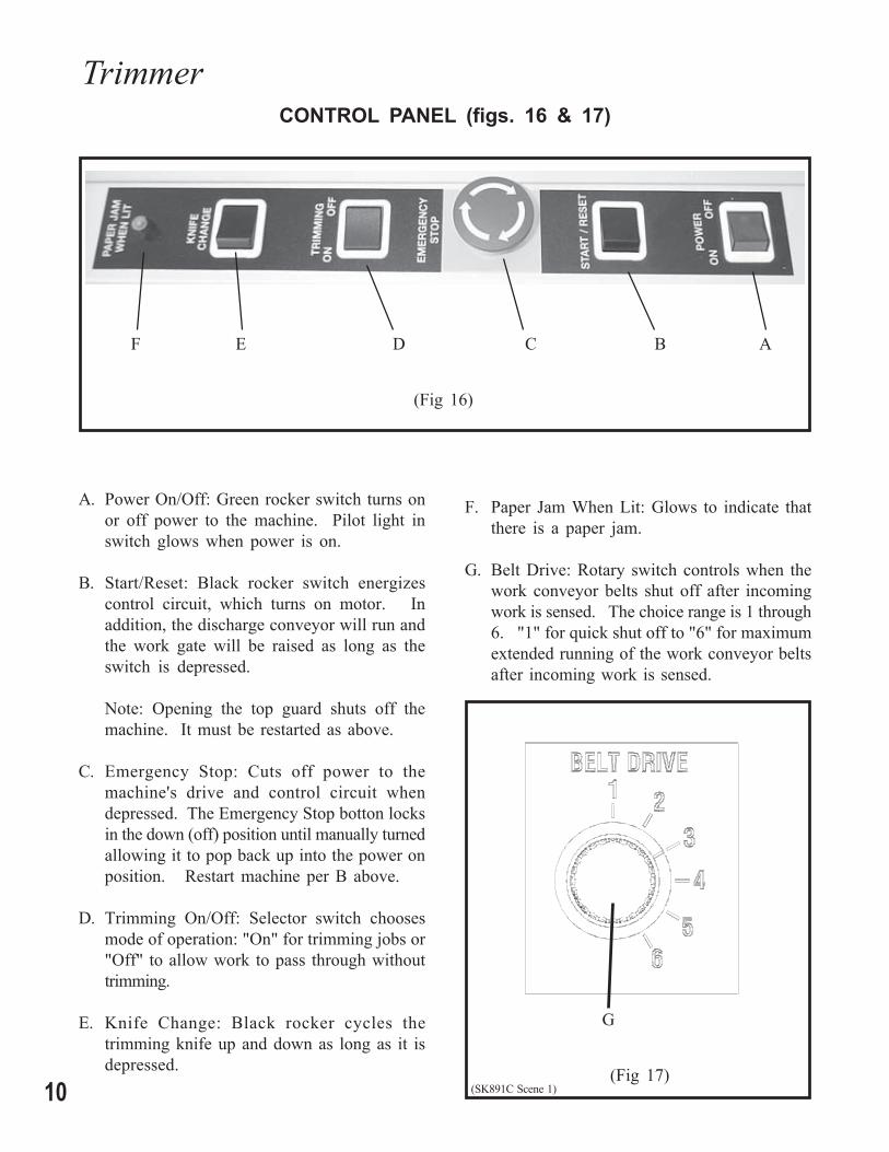
3. Install the safety interlock key that is hangingfrom the bottom of the back cover (see fig 9).
(Fig 6)
(Fig 7)
(Fig 8)
(Fig 9)

8
Trimmer
DISCHARGE CONVEYOR TABLE:
Install discharge conveyor table per illustrations(figs 10, 11, & 12).
(Fig 10) (Fig 11)
(Fig 12)

9
TRIMMER HEIGHT:
The height of the trimmer can be adjusted up ordown slightly by use of the threaded adjustablecasters and locking nuts on the bottom of the trim-mer or trimmer stand (fig 13).
SETUP
TRIM LENGTH:
To set the back stop assembly for the desired trimlength, loosen the two thumb screws (fig 14) andslide the back stop assembly forward or back-
DISCHARGE TABLE ROLLERS:
Set the discharge table rollers forward for smallbooklets or backward for large booklets. To adjustthe rollers, loosen thumb screws (fig 15), moveroller brackets to desired location, then retightenthumb screws.
(Fig 13)
(Fig 14)
(Fig 15)
ward to the desired location. There is a pointeron the side of the back stop assembly that pointsto a trim length scale installed on the inside wallof the trimmer. Once located in the desiredposition tighten the two thumb screws.
10
TrimmerCONTROL PANEL (figs. 16 & 17)
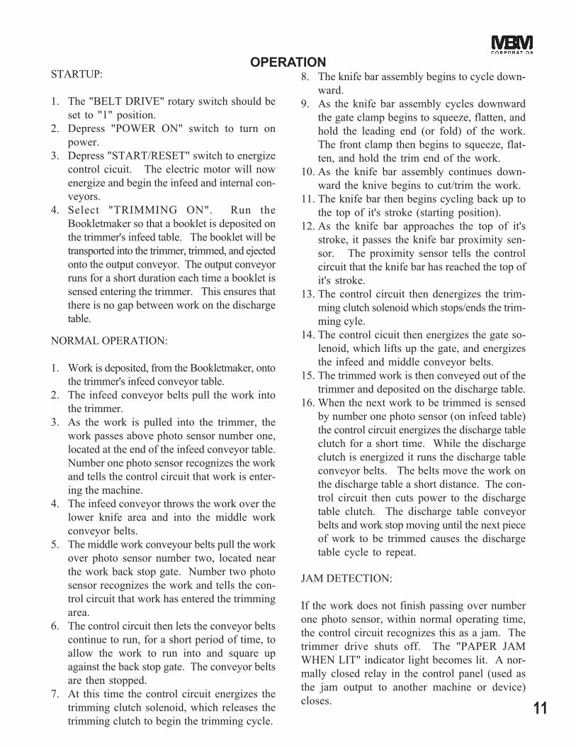
F E D C B A
(Fig 16)
A. Power On/Off: Green rocker switch turns onor off power to the machine. Pilot light inswitch glows when power is on.
B. Start/Reset: Black rocker switch energizescontrol circuit, which turns on motor. Inaddition, the discharge conveyor will run andthe work gate will be raised as long as theswitch is depressed.
Note: Opening the top guard shuts off themachine. It must be restarted as above.
C. Emergency Stop: Cuts off power to themachine's drive and control circuit whendepressed. The Emergency Stop botton locksin the down (off) position until manually turnedallowing it to pop back up into the power onposition. Restart machine per B above.
D. Trimming On/Off: Selector switch choosesmode of operation: "On" for trimming jobs or"Off" to allow work to pass through withouttrimming.
E. Knife Change: Black rocker cycles thetrimming knife up and down as long as it isdepressed. (Fig 17)
G
F. Paper Jam When Lit: Glows to indicate thatthere is a paper jam.
G. Belt Drive: Rotary switch controls when thework conveyor belts shut off after incomingwork is sensed. The choice range is 1 through6. "1" for quick shut off to "6" for maximumextended running of the work conveyor beltsafter incoming work is sensed.
(SK891C Scene 1)
11
NORMAL OPERATION:
1. Work is deposited, from the Bookletmaker, ontothe trimmer's infeed conveyor table.
2. The infeed conveyor belts pull the work intothe trimmer.
3. As the work is pulled into the trimmer, thework passes above photo sensor number one,located at the end of the infeed conveyor table.Number one photo sensor recognizes the workand tells the control circuit that work is enter-ing the machine.
4. The infeed conveyor throws the work over thelower knife area and into the middle workconveyor belts.
5. The middle work conveyour belts pull the workover photo sensor number two, located nearthe work back stop gate. Number two photosensor recognizes the work and tells the con-trol circuit that work has entered the trimmingarea.
6. The control circuit then lets the conveyor beltscontinue to run, for a short period of time, toallow the work to run into and square upagainst the back stop gate. The conveyor beltsare then stopped.
7. At this time the control circuit energizes thetrimming clutch solenoid, which releases thetrimming clutch to begin the trimming cycle.
OPERATION
JAM DETECTION:
If the work does not finish passing over numberone photo sensor, within normal operating time,the control circuit recognizes this as a jam. Thetrimmer drive shuts off. The "PAPER JAMWHEN LIT" indicator light becomes lit. A nor-mally closed relay in the control panel (used asthe jam output to another machine or device)closes.
8. The knife bar assembly begins to cycle down-ward.
9. As the knife bar assembly cycles downwardthe gate clamp begins to squeeze, flatten, andhold the leading end (or fold) of the work.The front clamp then begins to squeeze, flat-ten, and hold the trim end of the work.
10. As the knife bar assembly continues down-ward the knive begins to cut/trim the work.
11. The knife bar then begins cycling back up tothe top of it's stroke (starting position).
12. As the knife bar approaches the top of it'sstroke, it passes the knife bar proximity sen-sor. The proximity sensor tells the controlcircuit that the knife bar has reached the top ofit's stroke.
13. The control circuit then denergizes the trim-ming clutch solenoid which stops/ends the trim-ming cyle.
14. The control cicuit then energizes the gate so-lenoid, which lifts up the gate, and energizesthe infeed and middle conveyor belts.
15. The trimmed work is then conveyed out of thetrimmer and deposited on the discharge table.
16. When the next work to be trimmed is sensedby number one photo sensor (on infeed table)the control circuit energizes the discharge tableclutch for a short time. While the dischargeclutch is energized it runs the discharge tableconveyor belts. The belts move the work onthe discharge table a short distance. The con-trol circuit then cuts power to the dischargetable clutch. The discharge table conveyorbelts and work stop moving until the next pieceof work to be trimmed causes the dischargetable cycle to repeat.
STARTUP:
1. The "BELT DRIVE" rotary switch should beset to "1" position.
2. Depress "POWER ON" switch to turn onpower.
3. Depress "START/RESET" switch to energizecontrol cicuit. The electric motor will nowenergize and begin the infeed and internal con-veyors.
4. Select "TRIMMING ON". Run theBookletmaker so that a booklet is deposited onthe trimmer's infeed table. The booklet will betransported into the trimmer, trimmed, and ejectedonto the output conveyor. The output conveyorruns for a short duration each time a booklet issensed entering the trimmer. This ensures thatthere is no gap between work on the dischargetable.

12
Trimmer
JAM CLEARING & RESTART:
1. Turn off power to the trimmer.2. Remove work jam. DO NOT REACH UN-
DER THE KNIFE! SEVERE LACERA-TIONS OR DISMEMBERMENT COULDRESULT.
3. Close all safety covers.4. Depress "POWER ON" switch to turn on
power.3. Depress "START/RESET" switch to energize
control cicuit. The electric motor and con-veyor clutches will energize so trimming mayresume.
JAM OUTPUT:
When a jam occurs a normally closed relay in thecontrol panel closes. This relay is connected toa .141" diameter female phone jack outlet (fig 18)located on the power cord bracket. Any deviceplugged into the phone jack will receive a closedcircuit signal, which that device can use to shutdown any upstream machines feeding work to thetrimmer.
DANGERNEVER REACH UNDER THE
KNIFE! SEVERE LACERATIONSOR DISMEMBERMENT COULD
RESULT!
BELT DRIVE:
The purpose of the "BELT DRIVE" rotary switch(fig 19) is to make sure the work will square upagainst the back stop to provide a good square cutbooklet.
The "1" setting means that the internal conveyorbelts will shut off quickly after the work is sensedallowing time for the work to square up againstthe back stop.
If the work does not square up fully against theback stop before being trimmed, rotate the switchto postition "2". This position allows the internalconveyor belts to run for an additional short pe-riod of time (after the work is sensed) so that thework will square up before being trimmed.
Positions "3" through "6" allow for progressivelylonger conveyor belt running time for unusual work,such as work that may slip on the conveyor belts,to square up against the back stop.
(Fig 19)
(Fig 18)
(SK891C Scene 1)

13
MAINTENANCE
The instructions on the followingpages are for the use of trained
personnel only!
Attempting to perform repair andreplacement procedures without
proper training may causemachine damage or operator
injury!

14
TrimmerADJUSTMENTS
KNIFE BAR SENSOR ADJUSTMENT:
The knife bar must always stop at the top of it'sstroke in order for work to enter the trimmer. Ifthe knife bar stops too low work will not be ableto get past the front clamp and/or knife, and workjams will result.
The function of the knife bar sensor is to signal thecontrol circuit when the knife bar has reached thetop of it's stroke so that the control circuit candenergize the trimming clutch causing the knifebar to stop at the top of it's stroke.
1. With power on and drive motor running, usethe knife change toggle switch to jog the knifebar to the top of it's stroke. If you can notstop the knife bar at exactly the top of it'sstroke, it is better to stop it slightly before topof stroke rather than after top of stroke.
2. Turn off and unplug power.3. Remove the left cover.4. Loosen the screws of the knife bar sensor,
move the sensor so that the top of the sensoris even with the top of the knife bar (fig 20).
5. Reinstall the left cover.
BACK STOP GATE ADJUSTMENT:
The function of the back stop gate is to provide asurface for the work to square up against so thatthe knife will cut the work squarely. The backstop gate must be parallel to the bottom knife.1. Run several pieces of work through the trim
cycle.2. By looking at the work, determine how much
one side or the other of the back stop gatemust be moved forward or backward.
3. Turn off and unplug power.4. Remove rear discharge table.5. Remove rear upper cover.6. Open top cover.7. Slide backgage carriage to front of machine.8. Using a 3/8" box wrench and a 1/8" hex
wrench loosen and shift one of the shoulderscrews (fig 21) locating the back stop gate(which will also shift the back stop gate)forward or backward the amount needed tosquare up the trim. Note: It may be necessaryto first move one shoulder screw and then theother in order to obtain the maximum amountof adjustment.
9. Reinstall lower cover and discharge table.
(Fig 21)
(Fig 20)
15
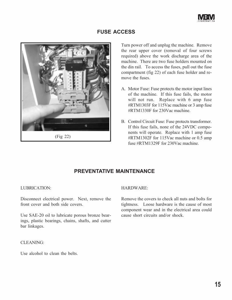
(Fig 22)
FUSE ACCESS
Turn power off and unplug the machine. Removethe rear upper cover (removal of four screwsrequired) above the work discharge area of themachine. There are two fuse holders mounted onthe din rail. To access the fuses, pull out the fusecompartment (fig 22) of each fuse holder and re-move the fuses.
A. Motor Fuse: Fuse protects the motor input linesof the machine. If this fuse fails, the motorwill not run. Replace with 6 amp fuse#RTM1303F for 115Vac machine or 3 amp fuse#RTM1330F for 230Vac machine.
B. Control Circuit Fuse: Fuse protects transformer.If this fuse fails, none of the 24VDC compo-nents will operate. Replace with 1 amp fuse#RTM1302F for 115Vac machine or 0.5 ampfuse #RTM1329F for 230Vac machine.
LUBRICATION:
Disconnect electrical power. Next, remove thefront cover and both side covers.
Use SAE-20 oil to lubricate porous bronze bear-ings, plastic bearings, chains, shafts, and cutterbar linkages.
CLEANING:
Use alcohol to clean the belts.
HARDWARE:
Remove the covers to check all nuts and bolts fortightness. Loose hardware is the cause of mostcomponent wear and in the electrical area couldcause short circuits and/or shock.
PREVENTATIVE MAINTENANCE

16
Trimmer
UPPER KNIFE REMOVAL & INSTALLATION:
CAUTION: Changing knives can be very dan-gerous unless safety precautions are observedand extreme care is taken when handlingknives
Keep handling of unprotected knives toan absolute minimum.
Warn people of any unprotected knife.
Knife changing is a ONE PERSON OP-ERATION. Having more than one per-son trying to change knives invites acci-dents.
1. Use the "Knife Change" rocker switch to movethe knife bar to the bottom of it's stroke.
2. Turn off power and unplug power cord.3. Remove bottom cover of infeed table.4. Remove front upper cover and the lower bar
that the front upper cover attaches to.5. Remove the left and right side covers.6. Remove the four screws and nuts holding the
top infeed table's conveyor bracket to the infeedtable.
7. Carefully lift the right side of the upper infeedconveyor bracket off the infeed table. Swingit out and lay it on the infeed table (fig 23).NOTE: Be sure the round belt does not comeoff pulleys and be sure the separating fingerstays between belts where they cross or theinfeed table conveyors wil not operate prop-erly when reassembled.
8. Loosen, BUT DO NOT REMOVE, all upperknife screws so that the upper knife can beslid away from the knife bar on the screwsabout 1/8 inch (fig 24).
9. Remove only the four middle knife screws sothat the two end screws remaining are holdingthe knife about 1/8 inch away from the knifebar (fig 25).
KNIFE REMOVAL & INSTALLATION
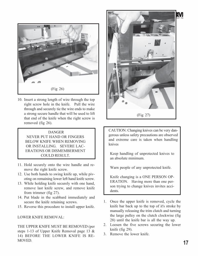
(Fig 23)
(Fig 25)
(Fig 24)
17
10. Insert a strong length of wire through the topright screw hole in the knife. Pull the wirethrough and securely tie the wire ends to makea strong secure handle that will be used to liftthat end of the knife when the right screw isremoved (fig 26).
DANGERNEVER PUT HAND OR FINGERS
BELOW KNIFE WHEN REMOVINGOR INSTALLING. SEVERE LAC-ERATIONS OR DISMEMBERMENT
COULD RESULT.
11. Hold securely onto the wire handle and re-move the right knife screw.
12. Use both hands to swing knife up, while piv-oting on remaining lower left hand knife screw.
13. While holding knife securely with one hand,remove last knife screw, and remove knifefrom trimmer (fig 27).
14. Put blade in the scabbard immediately andsecure the knife retaining screws.
15. Reverse this procedure to install upper knife.
LOWER KNIFE REMOVAL:
THE UPPER KNIFE MUST BE REMOVED (persteps 1-13 of Upper Knife Removal page 13 &14) BEFORE THE LOWER KNIFE IS RE-MOVED.
CAUTION: Changing knives can be very dan-gerous unless safety precautions are observedand extreme care is taken when handlingknives
Keep handling of unprotected knives toan absolute minimum.
Warn people of any unprotected knife.
Knife changing is a ONE PERSON OP-ERATION. Having more than one per-son trying to change knives invites acci-dents.
1. Once the upper knife is removed, cycle theknife bar back up to the top of it's stroke bymanually releasing the trim clutch and turningthe large pulley on the clutch clockwise (fig28) until the knife bar is all the way up.
2. Loosen the five screws securing the lowerknife (fig 29).
3. Remove the lower knife.
(Fig 26)
(Fig 27)

18
Trimmer
LOWER KNIFE INSTALLATION &ADUSTMENT:
THE UPPER KNIFE MUST BE REMOVED (persteps 1-13 of Upper Knife Removal pages 15-16)BEFORE THE LOWER KNIFE IS INSTALLED.
1. Once the upper knife is removed, cycle theknife bar back up to the top of it's stroke bymanually releasing the trim clutch and turningthe large pulley on the clutch clockwise ( fig28) until the knife bar is all the way up.
2. If installing a new or different lower knife,the set screws which push the lower knifeforward against the upper knife, must be turnedout so that the lower knife will not be in theway of the upper knife cycling down.
3. Install the five lower knife flat washers andscrews, but do not fully tighten because thelower knife must be free to move during thenext steps of installation/adjustments.
4. Manually cycle the knife bar (similar to stepone ) to the bottom of it's stroke. Install andsecure the upper knife per upper knife re-moval & installation procedure page 13 & 14
5. Push lower knife firmly against the upper knife.Turn the lower knife adjustment set screwsgently against the lower knife and secure withthe nuts. Manually release the trim clutchand turn pulley until knife bar is at top ofstroke.
6. Tighten the lower knife securing screws. DONOT PLACE FINGERS OR HAND BELOWUPPER KNIVE.
Lower Knife Securing Screws
(Fig 28)
(Fig 29)
WARNINGTURNING THE CLUTCH PULLEYCOUNTER CLOCKWISE AND/OR THEKNIFE PULL DOWN DRIVE SHAFT INREVERSE WILL DAMAGE THE CLUTCH.

19
7. Manually release the trim clutch and cycle theknife bar through one cycle to check that theupper knife blade passes the lower knifesmoothly without obstruction.
8. Place a single sheet of paper (large size) be-tween the upper and lower knives, manuallyrelease the trim clutch and cycle the knife barthrough one cycle. KEEP HANDS CLEAR!
9. Check that a clean cut is obtained across thefull width of the knive blades.
10. If necessary loosen the lower knive securingscrews at the point where adjustment isneeded. Loosen the lower knife bar adjust-ment screws/nuts, move the lower knife closerto the upper knife by turning the appropriateadjustment screw (fig 30) (1/6 turn at a time),retighten lower knife securing screws and nutsof adjustment screws.
11. Perform another test cut and make further ad-justments if necessary.
Lower KnifeAdjustment Screws
(Fig 30)
CLEARING A TRIMMING JAM:
If the maximum capacity of the trimmer is ex-ceeded (50 sheets of 20# stock or 0.20" workthickness) the trimming knife will stall near thebottom of the trim cycle and not finish cutting thework. If this happens the jam should be clearedby removing the upper knife (follow steps 2 through15 of UPPER KNIFE REMOVAL & INSTALLA-TION procedure page 16) and finishing the trimcycle by hand (follow step 1 of LOWER KNIFEINSTALLATION & ADJUSTMENT procedurepage 18).
WARNINGDO NOT TRY TO CLEAR THE TRIMMINGJAM BY TURNING THE CLUTCH PULLEYCOUNTER CLOCKWISE AND/OR BYTURNING THE KNIFE PULL DOWN DRIVESHAFT IN REVERSE OR THE CLUTCHWILL BE DAMAGED.

20
Trimmer
CAUTION: KNIFE SAFETY! Knives areDANGEROUS!!! They are heavy and verysharp, even after use. Keep the edge awayfrom your body and keep the area clear ofother people when handling knives. Nevertouch the cutting edge! To prevent personalinjury and damage to the knife, always keepknives in their holders with screws tight-ened. Others entering the area may not beaware of the dangers. Never attempt tohone, polish, or service the knife in any way.Failure to follow safety procedures may re-sult in severe lacerations or dismemberment.
Knife blade life, or the time between sharpenings,can be affected by many factors. One importantfactor is the type of paper being cut. Abrasivepaper, such as recycled paper, soft paper such asnewsprint paper, and bound books can all signifi-cantly shorten knife blade life. Cutting purepaper, such as bond paper with no recyled contentwill cause less wear on the cutting blade. In allcases the operator should continually check thequality of the cut to determine when the knifeneeds to be sharpened. Some characteristics thatindicate a blade needs sharpening are:
The knife hesitates or stalls while making acut.
The top sheets are not all cut to the samelength (usually the top few sheets are longerthan the rest of the sheets - this is sometimescalled "draw")
Cut marks appear on the cut face of the pa-per.
The knife and/or drive makes a "rough" soundas the knife passes through the paper.
Nicks are visible on the cutting edge of up-per or lower knife.
To prevent corrosion, knives are coated with lightoil. It should be REMOVED WITH CARE.
While removing or installing a knife, be carefulnot to allow the cutting edge to bump against themachine or other knife. Nicks will result.
If a knife bolt is damaged, replace it.
Always keep knife bolts securely tightened.
Store knives in a dry environment to prevent cor-rosion.
Never attempt to service a knife in any way with-out proprer training. It is recommended to main-tain a spare set of knives as a back up.
KNIFE CARE TIPS

21
NOTES:

22
TrimmerTROUBLE SHOOTING
PROBLEM:
1. The trimmer will not turn on.
2. Work is conveyed through trimmerwithout being trimmed.
3. Trim is not square to book.
4. Work is not trimmed clean.
5. The upper knife does not go up farenough to allow the work to pass be-low.
SOLUTION:
1. Plug unit into appropriate power supply.2. Depress the "Power On/Off" switch.3. If there is no green light:
a. Check for proper line voltage. (115V or 220V)b. Make sure the top guard is closed.c. Check the 1 amp control circuit fuse.
4. The green light is on, but the motor does not run.a. Depress the "Start/Reset" toggle switch.b. Check the 6A (115V) or 3A (220V) motor fuse.
1. Depress the "Trimming On/Off" switch to the "On"position.
2. Trim/Cut clutch problem.a. Check the connections at the clutch and circuit
board.3. Photo sensor problem.
a. Check the connections at the sensor and circuitboard.
4. Control circuit board problem.a. Check that knife bar begins cycle at top of
stroke.
1. The work does not stop flat against the back stop gate.a. Check that knife bar begins cycle at top of
stroke.b. Make sure all lower and upper conveyor belts
on the infeed table and middle conveyor areaare clean and operating properly.
c. Switch the "Belt Drive" rotary switch to thenext higher number postion.
2. Backstop gate is not square to lower knife.
1. Dull and/or damaged upper and/or lower knife.
2. Lower knife not adjusted properly to upper knife.
1. The proximity switch that senses the knife bar needs tobe adjusted upward.

23
1. Gate photosensor is being activated by an internalshaft, while in the shortest trimming position. Verifyby removing the back cover of the trimmer, and observethat L7 on the circuit board is off. See page 24.
a. Move trimming position to the min. 4" trimwidth.
b. Remove a pair of flat washers (item 32 on page31).
2. Gate photosensor is being activated by the gate clamp.a. Add a pair of flat washers (item 32 on page 31).
1. Maximum work thickness has been exceeded. See"CLEARING A TRIMMING JAM" on page 19.
6. Jam detection shuts down machine whenpaper crosses over infeed photosensor.
7. Knife stalls near bottom of trim cycleand does not cut through work.
24
Trimmer
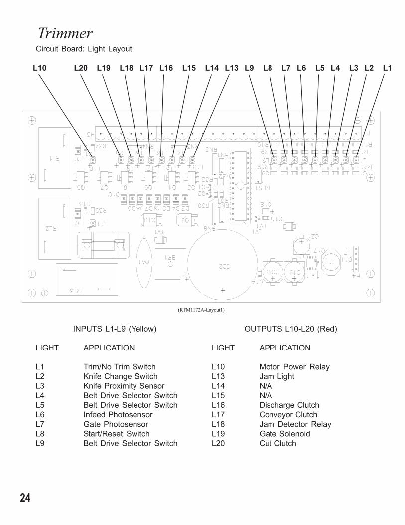
L10 L20 L19 L18 L17 L16 L15 L14 L13 L9 L8 L7 L6 L5 L4 L3 L2 L1
Circuit Board: Light Layout
INPUTS L1-L9 (Yellow)
LIGHT APPLICATION
L1 Trim/No Trim SwitchL2 Knife Change SwitchL3 Knife Proximity SensorL4 Belt Drive Selector SwitchL5 Belt Drive Selector SwitchL6 Infeed PhotosensorL7 Gate PhotosensorL8 Start/Reset SwitchL9 Belt Drive Selector Switch
OUTPUTS L10-L20 (Red)
LIGHT APPLICATION
L10 Motor Power RelayL13 Jam LightL14 N/AL15 N/AL16 Discharge ClutchL17 Conveyor ClutchL18 Jam Detector RelayL19 Gate SolenoidL20 Cut Clutch
(RTM1172A-Layout1)
25
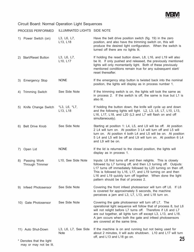
PROCESS PERFORMED
1) Power Switch (on)
2) Start/Reset Button
3) Emergency Stop
4) Trimming Switch
5) Knife Change Switch
6) Belt Drive Knob
7) Open Lid
8) Passing Work Through Trimmer
9) Infeed Photosensor
10) Gate Photosensor
11) Auto Shut-Down
* Denotes that the light may or may not be lit.
ILLUMINATED LIGHTS
L3, L6, L7,L13, L18
L3, L6, L7,L10, L17
NONE
See Side Note
*L3, L6, *L7,L13, L18
See Side Note
NONE
L10, See Side Note
See Side Note
See Side Note
L3, L6, L7, See SideNote
SIDE NOTE
Have the belt drive position switch (fig. 19) in the zeroposition, and also have the trimming switch on, this willproduce the desired light configuration. When the switch isturned off there are no lights lit.
If holding the reset button down, L8, L16, and L19 will alsobe lit. If only pushed and released, the previously mentionedlights will only momentarily light. Both of these previouslymentioned conditions remain true for any subsequent start/reset thereafter.
If the emergency stop button is twisted back into the nominalposition, the lights will display as in process number 1.
If the trimming switch is on, the lights will look the same asin process 2. If the switch is off, the same is true but L1 isalso lit.
If holding the button down, the knife will cycle up and downand the following lights will light. L2, L3, L6, L7, L10, L13,L16, L17, L18, and L20 (L3 and L7 will flash on and offsimultaneously).
Starting at position 1: L4, L5, and L9 will be off. At position2 L4 will turn on. At position 3 L4 will turn off and L5 willturn on. At position 4 both L4 and L5 will be on. At position5 L4 and L5 will be off and L9 will turn on. At position 6 L4and L9 will be on.
If the lid is returned to the closed position, the lights willdisplay as in process 1.
Inputs: L6 first turns off and then relights. This is closelyfollowed by L7 turning off, and then L3 turning off. Outputs:L17 turns off immediately followed by L20 turning on then off.This is followed by L16, L17, and L19 turning on and thenL16 and L19 quickly turn off together. When done the lightpattern should be that of process 2.
Covering the front infeed photosensor will turn off L6. If L6is covered for approximately 5 seconds, the machineperceives a jam and L3, L7, L13, and L18 turn on.
Covering the gate photosensor will turn off L7. Theoperational light sequence will follow that of process 8, but L6will not relight before L7 turns off. Therefore if L6 and L7are out together, all lights turn off except L3, L13, and L18.A jam occurs when both the gate and infeed photosensorsare covered at the same time.
If the machine is on and running but not being used forabout 2 minutes, it will auto shutdown. L10 and L17 will turnoff, and L13 and L18 go on.
Circuit Board: Normal Operation Light Sequences

26
Trimmer
Index Part Part Name NumberNumber Number Required
1 RBM1826A Index Collar Assembly 12 RTM1264A Pulley Assembly 13 RTM1261F Index Shaft 14 RTM1042F Wrap Spring Clutch 15 CB2125 Nylon Washer 26 D20609F Set Screw 1
Index Part Part Name NumberNumber Number Required
7 D25524F Roll Pin 18 D23940F Roll Pin 19 RTM1286F Clutch Mount Bracket 110 RBM1778F Bearing 211 RTM1288F Thrust Bearing 212 RTM1291F Wave Spring Washer 2
(RTM1286A Scene 2)
9
10
8
7
6
5
4
11
12
3
21
12
11
510

27
Index Part Part Name NumberNumber Number Required
Index Part Part Name NumberNumber Number Required
1 RTM1181F Bearing, "D" Flange 52 RTM1082F Shaft, Upper Drive 13 RTM1241F Pulley, Round Belt 14 RTM1078F Table, Lower Conveyor 15 RTM1081F Shaft, Lower Conveyor Drive 16 RTM1080F Cover, Upper Conveyor 17 RTM1243F Shaft, Upper Idler 18 RTM1052F Pulley, Crowned Flat Belt 49 RTM1053F Pullely, Flat Belt 210 RTM1244F Brace, Upper Cross 111 RTM1087F Belt, Upper Conveyor 212 RTM1346F Shaft, Lower Idler 113 RTM1088F Belt, Lower Conveyor 2
*14 RTM1338F Bracket, Infeed Sensor Mount 1*15 RTM1336F Sensor, Photoelectric 116 CB837C Retaining Ring, ø.250 Shaft 1017 CG26F Screw, .250-20 Button Head 818 CB493 Nut, .250-20 Hex. 619 RTM1236A Block Assembly 1
(RTM1089A Scene 2)
20 RTM1242A Support Assembly 221 CG26B Screw, 10-32 x 1.00 Button Hd 122 CB278 Nut, 10-32 Hex. 1
*23 CB56G2 Screw, 4-40 x 1.00 Soc. Hd. 2*24 CG13 Nut, 4-40 Hex. 225 CB206E Screw, 8-32 x .625 Fl. Hd. Soc. 226 CB719 Nut, 8-32 Hex. 227 RTM1274F Belt, Round 128 RTM1276F Separator, Round Belt 129 CG26A Screw, 10-32 x .500 Button Hd. 430 CB59H Screw, 8-32 x .375 Soc. Set 831 RTM1343F Pulley ø1.032, Flat Belt 232 RTM1344F Guard, Belt 133 RTM1345F Bumper, Allignment 234 CB860C Nut, Elastic Stop, .250-20 235 RBM1252F Screw, .250-20 x 1.00, Rd. Hd. 2
* When replacing original sensors and/or mountingbracketry on models prior to serial number 1050,ordersensor update kit CBBB3000E7.
1
2
3
4
5
6
7
31
9
1011
12
18
19
17
20
16
21
15
22
14
28
13
27
26
25
24
23
29
30
32
8
3334 35

28
Trimmer
(RTM1000A Scene 2)
Index Part Part Name NumberNumber Number Required
Index Part Part Name NumberNumber Number Required
1 RTM1111F Plate, Base 12 RTM1062F Tie Bar 63 RTM1284F Screw, .250-20 x 1.00 Fl. Hd. 44 CB493 Nut, .250-20 Hex. 75 RTM1113F Plate. L.H. Side 16 CB325 Screw, .250-20 x .500 Soc. Hd. 257 RTM1112F Plate, R.H. Side 18 RTM1282A Caster Assembly w/Brake 29 RTM1283A Caster Assembly w/o Brake 210 RTM1095F Tie Bar, Main 211 CB314A Screw, .375-16 x .75 Soc. Hd. 812 RTM1233F Bracket, Inner Table Support 113 RTM1005F Support, Lower Knife 114 RTM1280F Screw, .375-16 x .75 Button Hd. 415 RTM1011F Bearing, Flange Ball 216 CB328 Screw, .375-16 x .75 Hex. 417 D30541F Nut, .375-16 Hex. 1218 RTM1141A Assembly, Bearing 219 CB651A Screw, 10-24 x .75 Soc. Hd. 420 RTM1114A Power Panel Assembly 121 RTM1173F Bearing, "D" Flange, ø.375 I.D. 622 RTM1157F Bearing, "D" Flange, ø.500 I.D. 6
23 RTM1006F Bar, Lower Knife Adjustment 124 CB154A Screw, 10-24 x .625 Soc. Hd. 425 RTM1293F Screw, 10-24 x .625 Set, Fl. Pt. 426 D3797F Nut, 10-24 Hex. 427 RTM1089A Infeed Conveyor Assembly 128 RTM1248F Spacer, Short 329 RTM1257F Spacer, Long 130 CB617 Screw, .375-16 x 1.50 Soc. Hd. 831 RTM1161F Motor 132 D25947F Screw, .375-16 x 1.00 Hex. Hd. 433 RTM1031A Table, R.H. 134 RTM1032A Table, L.H. 135 CG26F Screw, .250-20 x .50 Button Hd. 436 CB718 Washer, Flat 437 RTM1286A Clutch Assembly, Discharge 138 RTM1314F Bracket, Interlock Switch 139 CB806 Washer, .250 Flat 240 CB51 Screw, .250-20 x .75 Soc. Hd. 241 RTM1326F Switch, Interlock 142 RTM1327A Key Assembly, Interlock 143 RTM1324F Screw, 6-32 x 1.25 Button Hd. 244 RTM1061F Trimmings Chute 1
520
262524
31
3334
32
4
2
1017
15
10
6
31
7
8
9
11
13
16
14
18 19
12
21
23
27 2829
22
30
37
36
3940
41
43 38
42
35 44

29
(RTM1000B Scene 5)
Index Part Part Name NumberNumber Number Required
Index Part Part Name NumberNumber Number Required
1 RTM1012F Shaft, Pull Down Drive 12 RTM1269A Support, Knife Shaft 13 RTM1108F Chain 14 RTM1287F Locking Collar 25 D29845F Roll Pin, .125 x .625 16 RTM1285F Key, .125 Sq. x .750 17 RTM1158F Key, .3125 Sq. x 1.000 1
*8 RTM1341F Sprocket, 30 Teeth, Driven 19 RTM1036F Shaft, Reduction 1
*10 RTM1342F Sprocket, 12 Teeth, Drive 111 RTM1041F Pulley, 27XL Timing 112 RTM1267F Pulley 15XL Timing 113 RTM1038F Pulley, 15L Timing 114 RTM1281F E-Ring, Retaining, ø.500 1215 CB154 Screw, 10-32 x .625 Soc. Hd. 316 RTM1120F Pulley, 36L Timing 117 CB629D Screw, .250-20 x 2.0 Soc. Hd. 118 RTM1093F Clutch, Wrap Spring w/Brake 119 RTM1039A Pulley Assembly, 27XL 120 CB651A Screw, 10-24 x .75 Soc. Hd. 121 CB837E Retaining Ring, ø.500 Shaft 722 CB837B Retaining Ring, ø.375 Shaft 823 RTM1135F Pulley, Crowned, ø.500 Bore 224 RTM1234F Pulley, Crowned, ø.375 Bore 225 RTM1042F Clutch Wrap Spring 126 RTM1235F Pulley, Flat, ø.375 Bore 2
27 RTM1138F Pulley, Flat, ø.500 Bore 228 RTM1253F Shaft 129 RTM1088F Belt, Endless Table 430 RTM1050F Shaft, Upper Conveyor Drive 131 RTM1049F Shaft, Conveyor Drive 132 CB835F2 Roll Pin, .093 x .625 233 RTM1258F Gear, Spur 234 RTM1048F Pulley, 15XL Timing 135 RTM1051F Shaft, Conveyor Driven 136 RTM1143F Pulley, 18XL Timing 137 CB837C Retaining Ring, ø.250 Shaft 238 RTM1034F Pulley, 14XL Timing 139 RTM1035F Pulley, 80XL Timing 140 RTM1037F Pulley, 20XL Timing 241 RTM1094F Shaft, Knife Clutch 142 RTM1043F Shaft, Infeed Clutch 143 D23940F Roll Pin, .125 x .875 144 CB493 Nut, .250-20 Hex. 145 D3797F Nut, 10-24 Hex. 146 CB59D Screw, .250-20 x .25 Soc. Set 847 CB371 Lockwasher, No. 10 3
* When replacing original 28 or 14 tooth sprocket onmodels prior to serial number 1050, you must replaceBOTH at the same time with the indicated items 8 and10.
65
43
21
7
8
910
11
13
1716 15
14
18
19
12
2021
23
2726
2524
28
29
22
3031
33
37
36 35
34
3839
32
40
4142
43
44
45 47
46
30
Trimmer
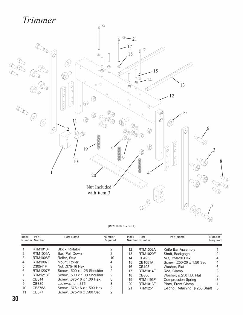
(RTM1000C Scene 1)
Index Part Part Name NumberNumber Number Required
Index Part Part Name NumberNumber Number Required
1 RTM1010F Block, Rotator 22 RTM1009A Bar, Pull Down 23 RTM1008F Roller, Stud 104 RTM1007F Mount, Roller 45 D30541F Nut, .375-16 Hex. 86 RTM1207F Screw, .500 x 1.25 Shoulder 27 RTM1213F Screw, .500 x 1.00 Shoulder 28 CB314 Screw, .375-16 x 1.00 Hex. 89 CB889 Lockwasher, .375 810 CB375A Screw, .375-16 x 1.500 Hex. 211 CB377 Screw, .375-16 x .500 Set 2
12 RTM1002A Knife Bar Assembly 113 RTM1020F Shaft, Backgage 214 CB493 Nut, .250-20 Hex. 415 CB1051A Screw, .250-20 x 1.50 Set 416 CB198 Washer, Flat 617 RTM1014F Rod, Clamp 318 CB806 Washer, ø.250 I.D. Flat 319 RTM1193F Compression Spring 320 RTM1013F Plate, Front Clamp 121 RTM1251F E-Ring, Retaining, ø.250 Shaft 3
6
5
4
3
2
1
7
89
10
11
13
16
15
14
12
1721
18
19
20
Nut Includedwith item 3

31
(RTM1000C Scene 3)
Index Part Part Name NumberNumber Number Required
Index Part Part Name NumberNumber Number Required
1 RTM1022F Carriage, Backgage 12 RTM1230F Rail 23 RTM1014F Rod, Clamp 24 RTM1231F Bracket, Gate Support 1
*5 RTM1339F Clamp, Gate 16 RTM1023F Solenoid 1
*7 RTM1337F Brace, Gate Sensor 18 RTM1238F Gate 18A RTM1238F-A Gate, 4 Head Loop Stitch Option19 RTM1240F Link, Gate 110 CB1421E Screw, ø.250 Shoulder 211 CB1262 Washer, ø.203 I.D. Flat 212 RTM1245F Bearing, Flanged 213 CB890 Screw, .312-18 x 1.00 Fl. Pt. 2
Soc. Set.*15 RTM1336F Sensor, Photoelectric 116 CB806 Washer, ø.250 I.D. Flat 2
17 RTM1251F E-Ring, Retaining, ø.250 Shaft 2*18 CB56G2 Screw, 4-40 x 1.0 Soc. Hd. 219 RTM1255F Pointer, Backgage Position 120 CG26L Screw, 8-32 x .25 Button Hd. 221 RTM1033F Knob, Carriage Lock 222 CB325 Screw, .250-20 x .625 Soc. Hd. 1423 RTM1189F Bearing, Sleeve, .50x.625x.375 424 CB835M2 Pin, .125 x .500 Roll 325 D3797F Nut, 6-32 Hex. 228 RTM1192F Spring, Compression 229 RTM1188F Bearing, Sleeve 230 RTM1307F Washer, Flat 4
*32 CP74 Washer, No. 4, Flat 8
* When replacing original sensors and/or mountingbracketry on models prior to serial number 1050, ordersensor update kit CBBB3000E7.
6
5
4
3
2
1
7
8
9
10
11
13
17
16
15
18
19
12
20
21
23
25
24
28
29
22
30
32
(RTM1238F-A layout2)
8A
Optional Gate foruse with 9.45" loopstitch centers
32
Trimmer
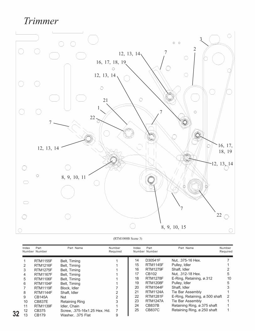
(RTM1000B Scene 3)
Index Part Part Name NumberNumber Number Required
Index Part Part Name NumberNumber Number Required
1 RTM1155F Belt, Timing 12 RTM1216F Belt, Timing 13 RTM1275F Belt, Timing 14 RTM1167F Belt, Timing 15 RTM1106F Belt, Timing 16 RTM1104F Belt, Timing 17 RTM1119F Block, Idler 78 RTM1144F Shaft, Idler 29 CB145A Nut 210 CB837E Retaining Ring 311 RTM1139F Idler, Chain 112 CB375 Screw, .375-16x1.25 Hex. Hd. 713 CB179 Washer, .375 Flat 9
14 D30541F Nut, .375-16 Hex. 715 RTM1145F Pulley, Idler 116 RTM1279F Shaft, Idler 217 CB102 Nut, .312-18 Hex. 518 RTM1278F E-Ring, Retaining, ø.312 1019 RTM1208F Pulley, Idler 520 RTM1044F Shaft, Idler 321 RTM1124A Tie Bar Assembly 122 RTM1281F E-Ring, Retaining, ø.500 shaft 223 RTM1247A Tie Bar Assembly 124 CB837B Retaining Ring, ø.375 shaft 125 CB837C Retaining Ring, ø.250 shaft 1
3
2
1
7
8, 9, 10, 11
16, 17, 18, 19
8, 9, 10, 15
12, 13, 14
21
22
12, 13, 14
12, 13, 14
12, 13, 14
7
7
7
16, 17,18, 19
22

33
(RTM1000B Scene 6)
6 5
4
17, 18, 19, 20
23
25
24
12, 13, 14
12, 13, 14
12, 13, 14
7
7
7
17, 18, 19, 20
17, 18, 19, 20

34
Trimmer
(RTM1000C Scene 6)
Index Part Part Name NumberNumber Number Required
Index Part Part Name NumberNumber Number Required
1 RTM1003F Upper Knife 12 CB371B Washer, ø.437 Lock 63 RTM1309F Screw, .437-24x1.00 Button Hd. 6
6
54
3
2
1
4 RTM1004F Lower Knife 15 CB1262 Washer, No. 10 Flat 56 CB651A Screw, 10-24 x .75 Soc. Hd. 5
35
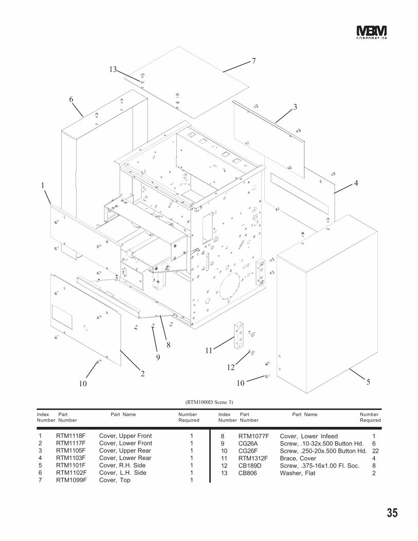
(RTM1000D Scene 3)
Index Part Part Name NumberNumber Number Required
Index Part Part Name NumberNumber Number Required
1 RTM1118F Cover, Upper Front 12 RTM1117F Cover, Lower Front 13 RTM1105F Cover, Upper Rear 14 RTM1103F Cover, Lower Rear 15 RTM1101F Cover, R.H. Side 16 RTM1102F Cover, L.H. Side 17 RTM1099F Cover, Top 1
8 RTM1077F Cover, Lower Infeed 19 CG26A Screw, .10-32x.500 Button Hd. 610 CG26F Screw, .250-20x.500 Button Hd. 2211 RTM1312F Brace, Cover 412 CB189D Screw, .375-16x1.00 Fl. Soc. 813 CB806 Washer, Flat 2
6
5
4
3
2
1
7
98
10
12
11
10
13
36
Trimmer
(RTM1114A)
6
4, 5, 28
2, 3, 4, 5
1
8, 9, 10
11
13
17
14, 15, 16 12
20
2123
2725, 26
2422
31
3334
32
22
19
18
7
30
29
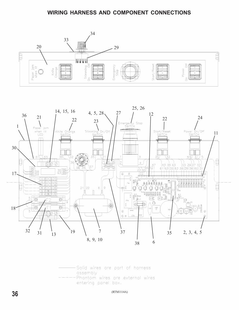
WIRING HARNESS AND COMPONENT CONNECTIONS
3537
36
38

37
Index Part Part Name NumberNumber Number Required
Index Part Part Name NumberNumber Number Required
1 RTM1114F Power Panel 12 RTM1171F Stand Off 43 RTM1176F Screw 6-32 x .25 (stand off) 44 CK50 Lockwasher, No. 6 85 CB720 Nut, 6-32 Nex. 66 RTM1172A Printed Circuit Board 17 RTM1170F Transformer 18 CG26N Screw, 8-32x.375 (transformer) 29 CB988A Lockwasher, No. 8 210 CB719 Nut, 8-32 Hex. 211 RTM1217F Plug, PCB, 10 Pin 212 RTM1218F Plug, PCB, 6 Pin 113 RTM1199F Rail, Terminal Block 114 CG26K Screw, 10-32 x .25 Button Hd. 215 CB278 Nut, 10-32 Hex. 216 CB988 Washer, No. 10 217 RTM1196F Terminal Block 618 RTM1202F Fuse Block Terminal 219 RTM1197F Terminal End Bracket 220 RTM1168F Decal, Controls 121 RTM1162F Indicator Assembly, LED 122 CG137 Rocker Switch 223 CG138 Rocker Switch 1
24 RTM1169F On/Off Rocker Switch (115Vac) 1RTM1331F On/Off Rocker Switch (230Vac) 1
25 RBM1491F Emergency Stop 126 RBM1492F Contact Block 127 RBM1240F Terminal Block 128 RTM1219F Screw, 6-32 x .75 Button Hd. 2
*29 RTM1311A2 Rotary Switch 130 RTM1294F Relay Module 131 RTM1303F Fuse, 6A, Time Delay (115Vac) 1
RTM1330F Fuse, 3A, Time Delay (230Vac) 132 RTM1302F Fuse, 1A, Time Delay (115Vac) 1
RTM1329F Fuse, .5A, Time Delay (230Vac) 1*33 RTM1306F2 Decal, Belt Drive 134 RBM1419F Knob 1
*35 RTM1295F8 Microchip 136 RTM1304F Wire Harness 137 RTM1328F Wire Assembly 238 RTM1333F Fuse, 2A, Time-lag 1
* When replacing original switch or microchip on modelsprior to serial number 1050, you must replace switch,decal, and microchip.
38
Trimmer
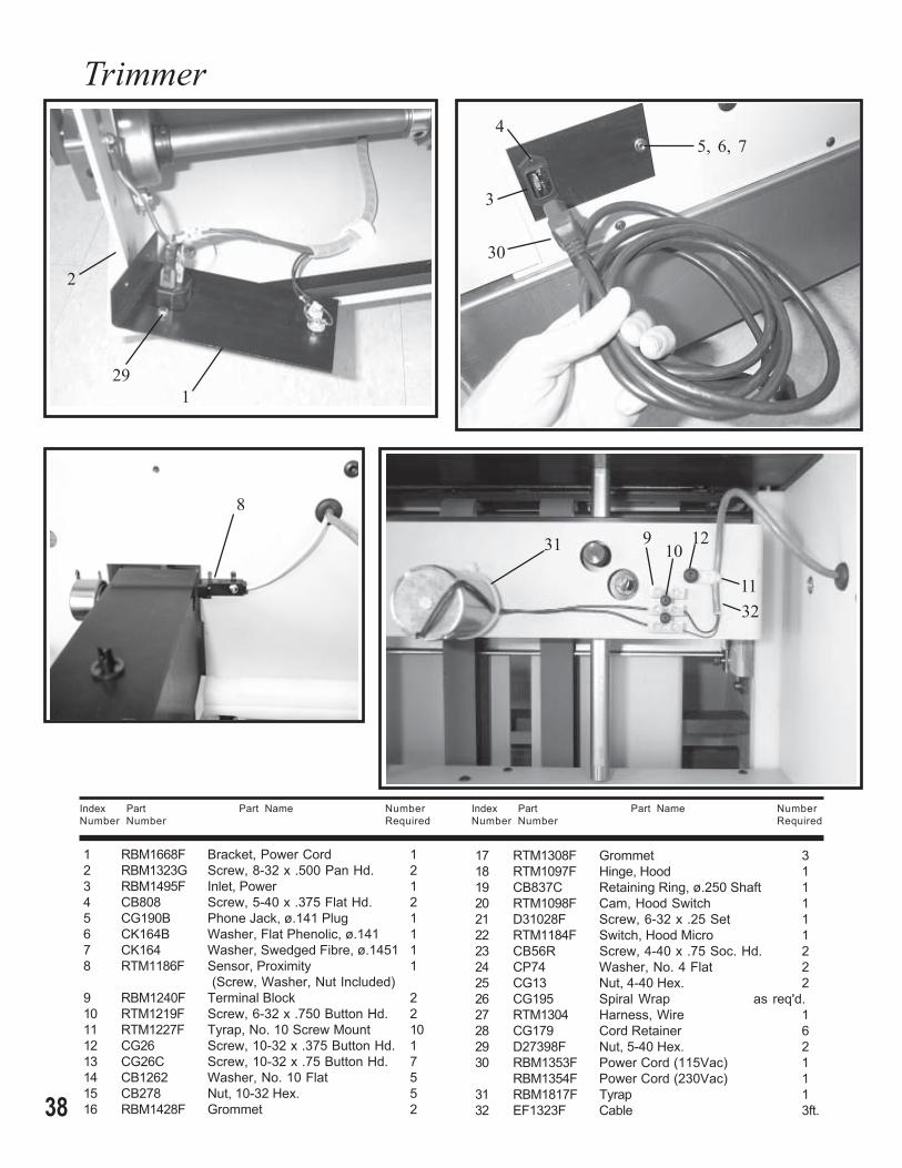
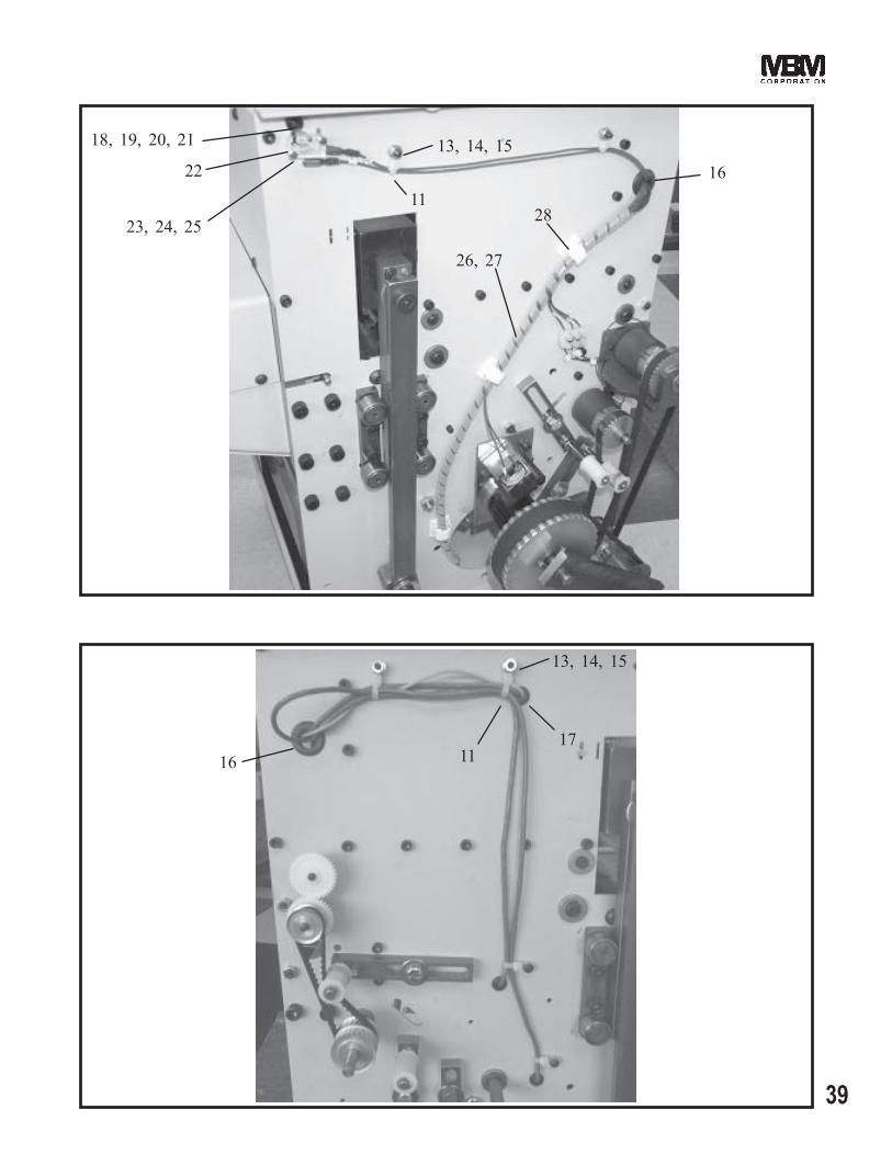
Index Part Part Name NumberNumber Number Required
Index Part Part Name NumberNumber Number Required
1 RBM1668F Bracket, Power Cord 12 RBM1323G Screw, 8-32 x .500 Pan Hd. 23 RBM1495F Inlet, Power 14 CB808 Screw, 5-40 x .375 Flat Hd. 25 CG190B Phone Jack, ø.141 Plug 16 CK164B Washer, Flat Phenolic, ø.141 17 CK164 Washer, Swedged Fibre, ø.1451 18 RTM1186F Sensor, Proximity 1
(Screw, Washer, Nut Included)9 RBM1240F Terminal Block 210 RTM1219F Screw, 6-32 x .750 Button Hd. 211 RTM1227F Tyrap, No. 10 Screw Mount 1012 CG26 Screw, 10-32 x .375 Button Hd. 113 CG26C Screw, 10-32 x .75 Button Hd. 714 CB1262 Washer, No. 10 Flat 515 CB278 Nut, 10-32 Hex. 516 RBM1428F Grommet 2
17 RTM1308F Grommet 318 RTM1097F Hinge, Hood 119 CB837C Retaining Ring, ø.250 Shaft 120 RTM1098F Cam, Hood Switch 121 D31028F Screw, 6-32 x .25 Set 122 RTM1184F Switch, Hood Micro 123 CB56R Screw, 4-40 x .75 Soc. Hd. 224 CP74 Washer, No. 4 Flat 225 CG13 Nut, 4-40 Hex. 226 CG195 Spiral Wrap as req'd.27 RTM1304 Harness, Wire 128 CG179 Cord Retainer 629 D27398F Nut, 5-40 Hex. 230 RBM1353F Power Cord (115Vac) 1
RBM1354F Power Cord (230Vac) 131 RBM1817F Tyrap 132 EF1323F Cable 3ft.
1
8
910
11
12
5, 6, 74
3
2
29
30
31
32
39
13, 14, 15
18, 19, 20, 21
1716
22
23, 24, 25
16
26, 27
28
11
11
13, 14, 15
40
Trimmer
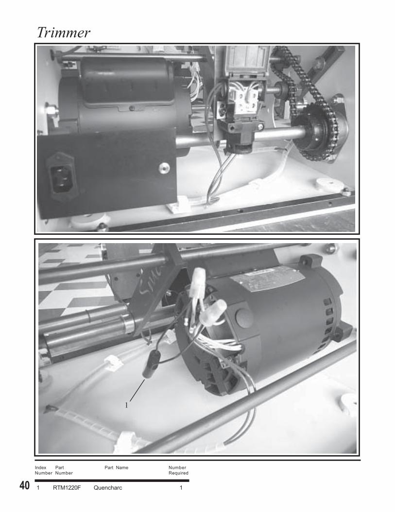
Index Part Part Name NumberNumber Number Required
1 RTM1220F Quencharc 1
1

41
(RTM1161F)
MOTOR WIRING
42
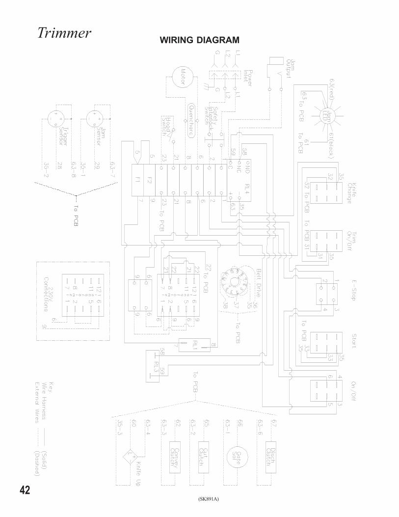
Trimmer
(SK891A)
WIRING DIAGRAM

43
ELECTRICAL SCHEMATIC
(SK891)

FORM QF110 5-20-04
3134 Industry Dr. N. Charleston, SC 294181-800-223-2508 1-843-552-2700
Fax: 1-843-552-2974www.mbmcorp.com