Embed Size (px)
Citation preview
STFC Technology
undulator manufacture and measurement
James Rochford On behalf of the Helical collaboration
2
Slide titleScope of presentation
•Current status
• Where we are at the moment
• Plans for the coming months
•Prototype design, manufacture, testing
• 4m Module design
• Magnet Testing and integration
• Assembly of 4m module
• First tests of the final prototype
•Introduction
• Undulator specification
3
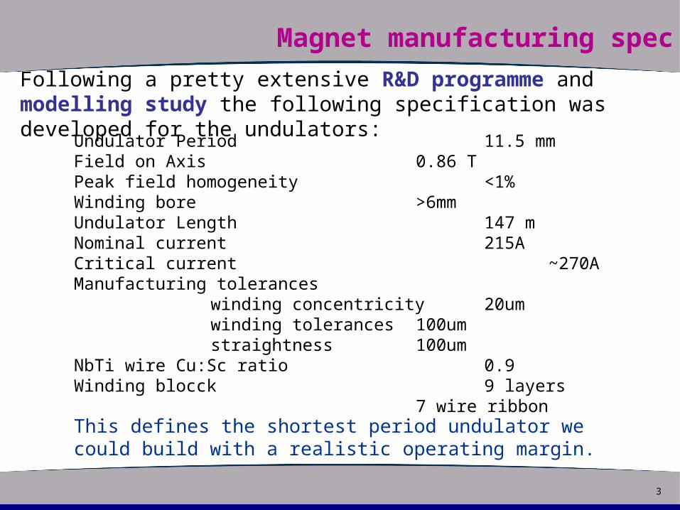
Slide titleMagnet manufacturing spec
Following a pretty extensive R&D programme and modelling study the following specification was developed for the undulators:
Undulator Period 11.5 mm Field on Axis 0.86 TPeak field homogeneity <1%Winding bore >6mmUndulator Length 147 mNominal current 215ACritical current ~270A Manufacturing tolerances
winding concentricity 20umwinding tolerances 100umstraightness 100um
NbTi wire Cu:Sc ratio 0.9 Winding blocck 9 layers
7 wire ribbon This defines the shortest period undulator we could build with a realistic operating margin.
4
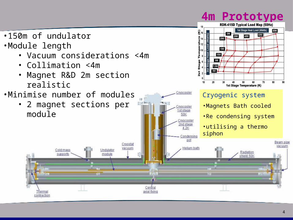
Slide title4m Prototype
•150m of undulator•Module length
• Vacuum considerations <4m• Collimation <4m• Magnet R&D 2m section
realistic•Minimise number of modules
• 2 magnet sections per moduleCryogenic system
•Magnets Bath cooled
•Re condensing system
•utilising a thermo siphon
5
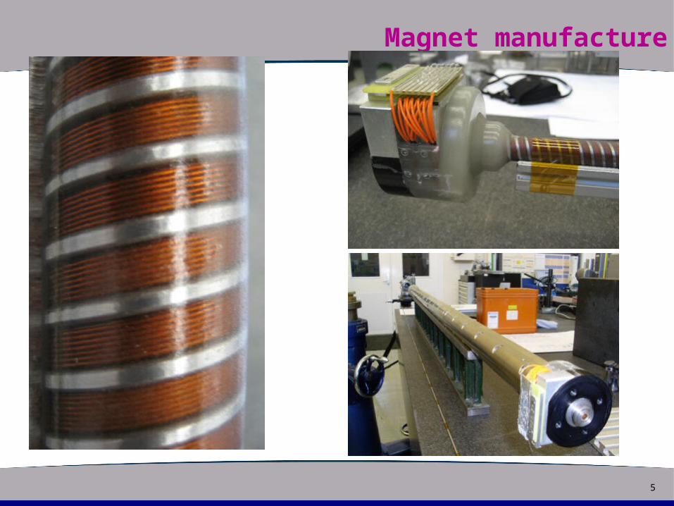
Slide titleMagnet manufacture
6
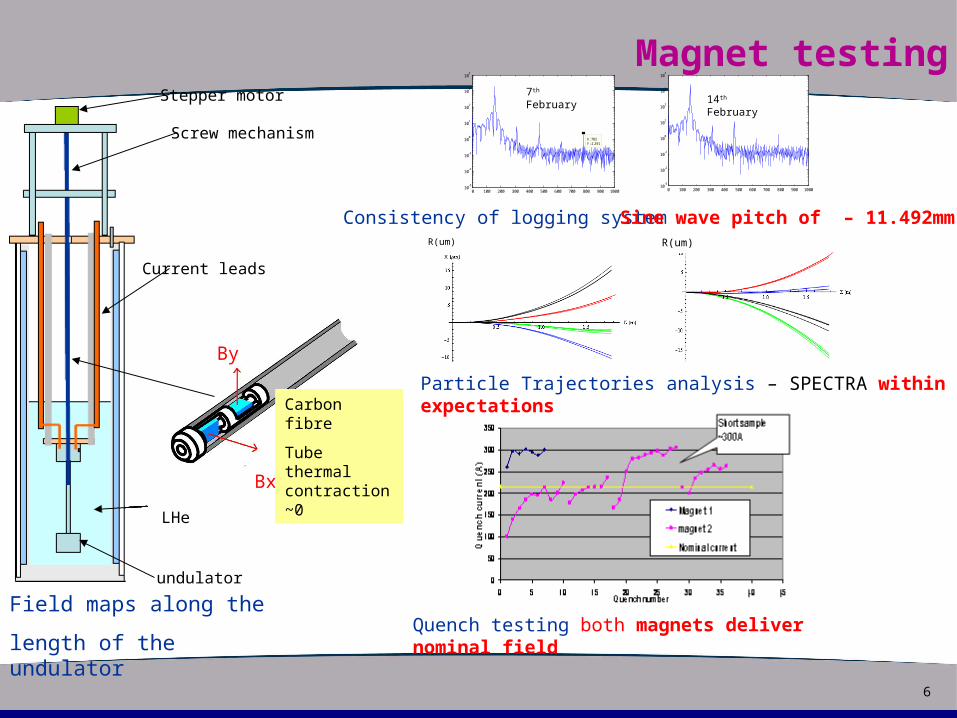
Slide titleMagnet testing
Field maps along the
length of the undulator
Current leads
LHe
undulator
Stepper motor
Screw mechanism
Bx
By
Carbon fibre
Tube thermal contraction~0
Consistency of logging systemSine wave pitch of – 11.492mmR(um) R(um)
Particle Trajectories analysis – SPECTRA within expectations
Quench testing both magnets deliver nominal field
0 100 200 300 400 500 600 700 800 900 100010
-3
10-2
10-1
100
101
102
103
104
X: 782Y: 2.291
0 100 200 300 400 500 600 700 800 900 100010
-3
10-2
10-1
100
101
102
103
104
7th February 14th
February
7
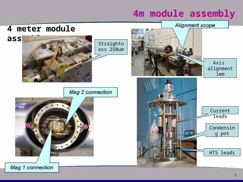
Slide title4m module assembly
4 meter module assembly
Straightness 250um
Axis alignment
1mm
Condensing pot
Current leads
HTS leads
8
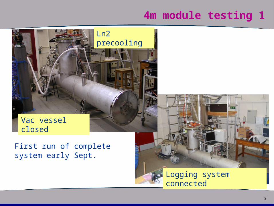
Slide title4m module testing 1
Vac vessel closed
Ln2 precooling
Logging system connected
First run of complete system early Sept.
9
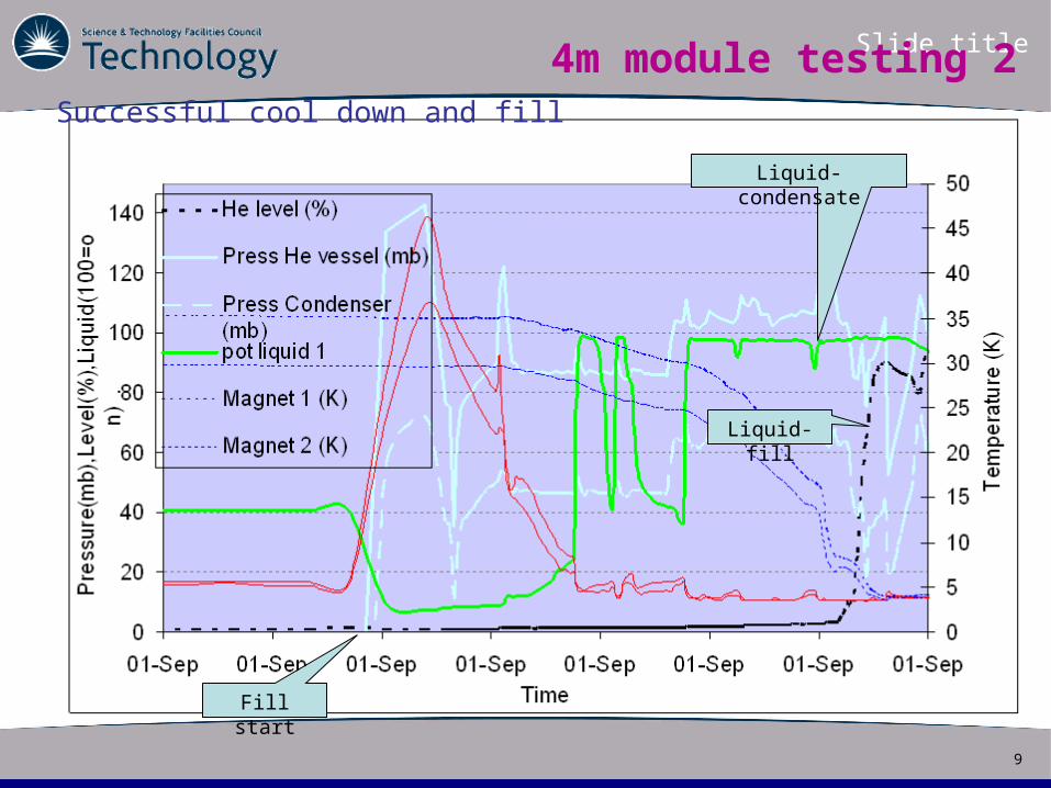
Slide title
Successful cool down and fill
4m module testing 2
Liquid-condensate
Liquid-fill
Fill start
10
Slide title4m module testing 3
The 1st cool down was successful
Filled system successfully
Siphon operation seems good
However had serious problem
Large heat leak evident
Rapid boil off of liquid
Loss of vacuum in magnet bore (Beam tube)
Liquid helium leak into magnet bore
System not stable enough to put current into the magnets
System had to be warmed
11
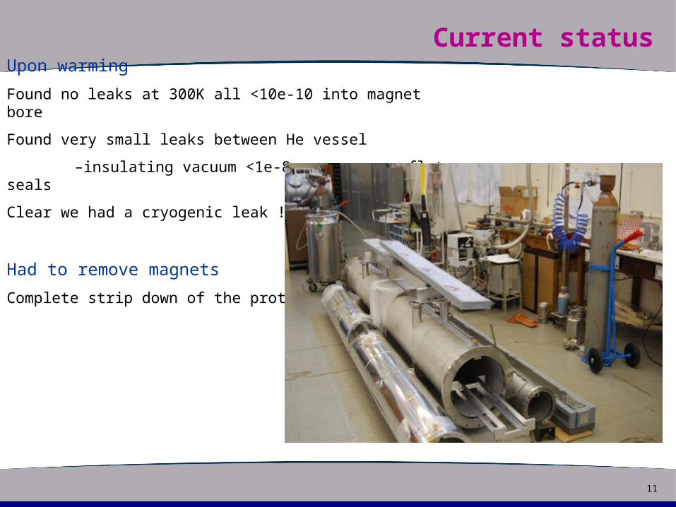
Slide titleCurrent status Upon warming
Found no leaks at 300K all <10e-10 into magnet bore
Found very small leaks between He vessel
–insulating vacuum <1e-8 – copper conflate seals
Clear we had a cryogenic leak !
Had to remove magnets
Complete strip down of the prototype
12
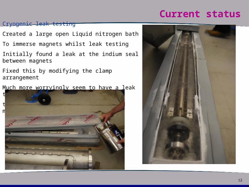
Slide titleCurrent status Cryogenic leak testing
Created a large open Liquid nitrogen bath
To immerse magnets whilst leak testing
Initially found a leak at the indium seal between magnets
Fixed this by modifying the clamp arrangement
Much more worryingly seem to have a leak through
the magnet structure, on magnet 1 and magnet 2
13
Slide titleCurrent status
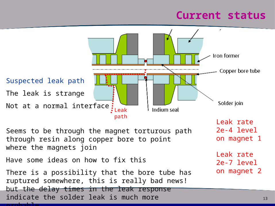
Suspected leak path
The leak is strange
Not at a normal interface
Seems to be through the magnet torturous path through resin along copper bore to point where the magnets join
Have some ideas on how to fix this
There is a possibility that the bore tube has ruptured somewhere, this is really bad news! but the delay times in the leak response indicate the solder leak is much more probable
Leak path
Leak rate 2e-4 level on magnet 1
Leak rate 2e-7 level on magnet 2
14
Slide titleCurrent status
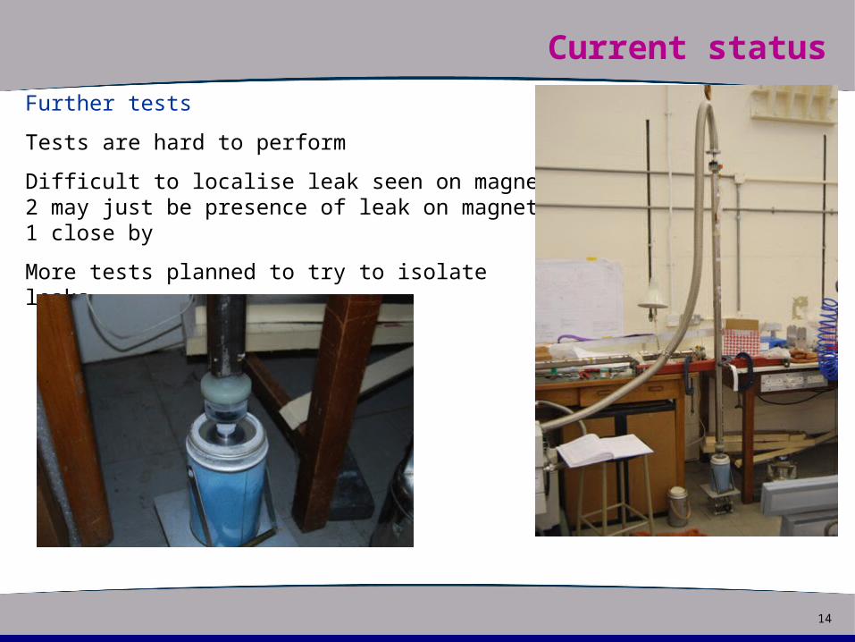
Further tests
Tests are hard to perform
Difficult to localise leak seen on magnet 2 may just be presence of leak on magnet 1 close by
More tests planned to try to isolate leaks
15
Slide titleFuture plans
Confirm leaks Confident we can fix the leak with sty castWill check this by cooling with LN2 as for leak tests described earlierRepeat prototype build with an additional stepOnce the magnets are integrated in the vac vessel We will cool using the LN2 circuit and leak checkprior to connecting the turretIf ok we will proceed with the build
Finish Rebuild of prototype Hopefully by ChristmasNext cool down Power magnets to nominal current This will probably be in the new year
Stability testsWarm up Bore heater tests More quench tests of magnet 2