Embed Size (px)
Citation preview

STCRobot
Optimally Covering an Unknown Indoor Environment
Majd Srour, Anis AbboudUnder the supervision of: Yotam Elor and Prof. Alfred Bruckstein
STC Robot
Task Description
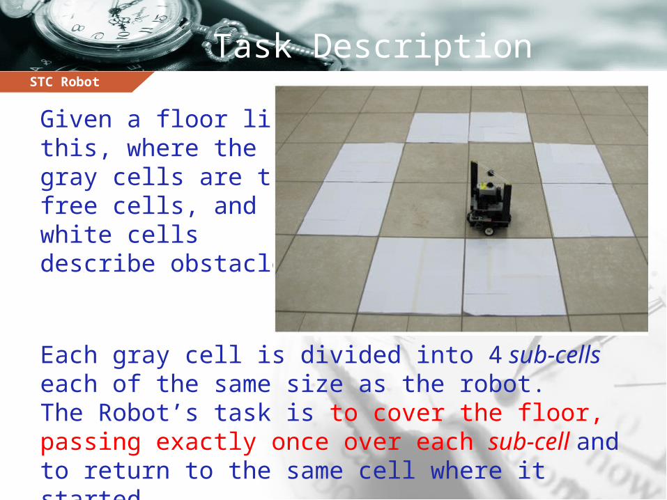
Given a floor like this, where the gray cells are thefree cells, and white cells describe obstacles.
Each gray cell is divided into 4 sub-cells each of the same size as the robot.The Robot’s task is to cover the floor, passing exactly once over each sub-cell and to return to the same cell where it started.
STC Robot
The On-line STC Algorithm
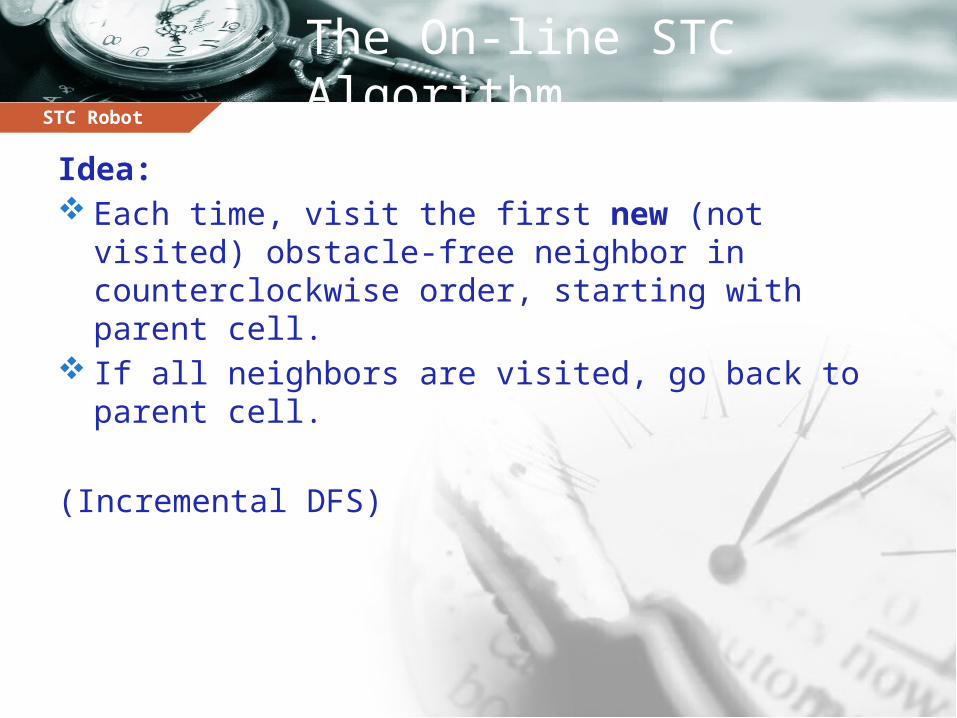
Idea: Each time, visit the first new (not visited) obstacle-
free neighbor in counterclockwise order, starting with parent cell.
If all neighbors are visited, go back to parent cell.
(Incremental DFS)
STC Robot
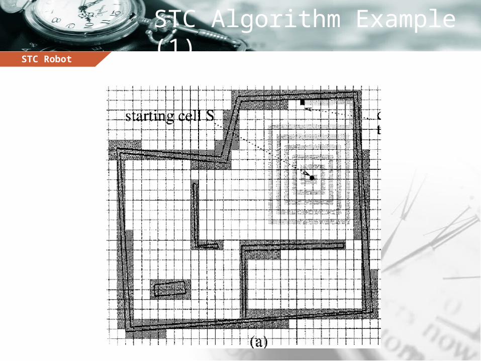
STC Algorithm Example (1)
STC Robot
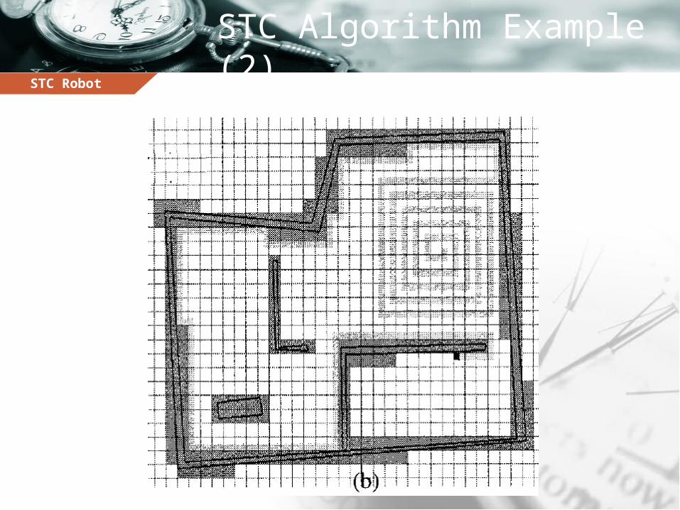
STC Algorithm Example (2)
STC Robot
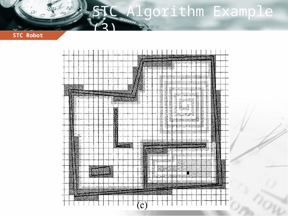
STC Algorithm Example (3)
STC Robot
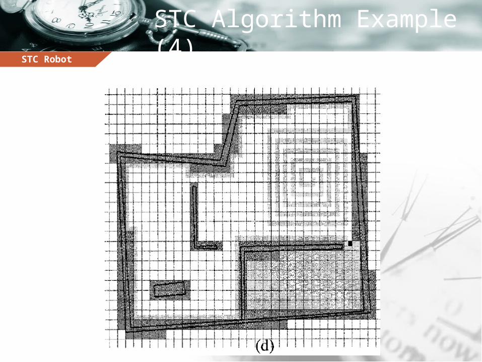
STC Algorithm Example (4)
STC Robot
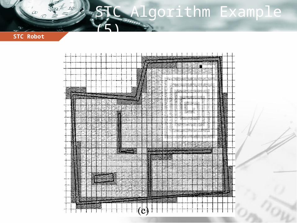
STC Algorithm Example (5)
STC Robot
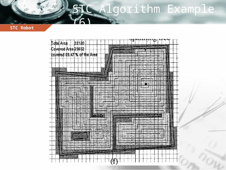
STC Algorithm Example (6)
STC Robot
The Robot
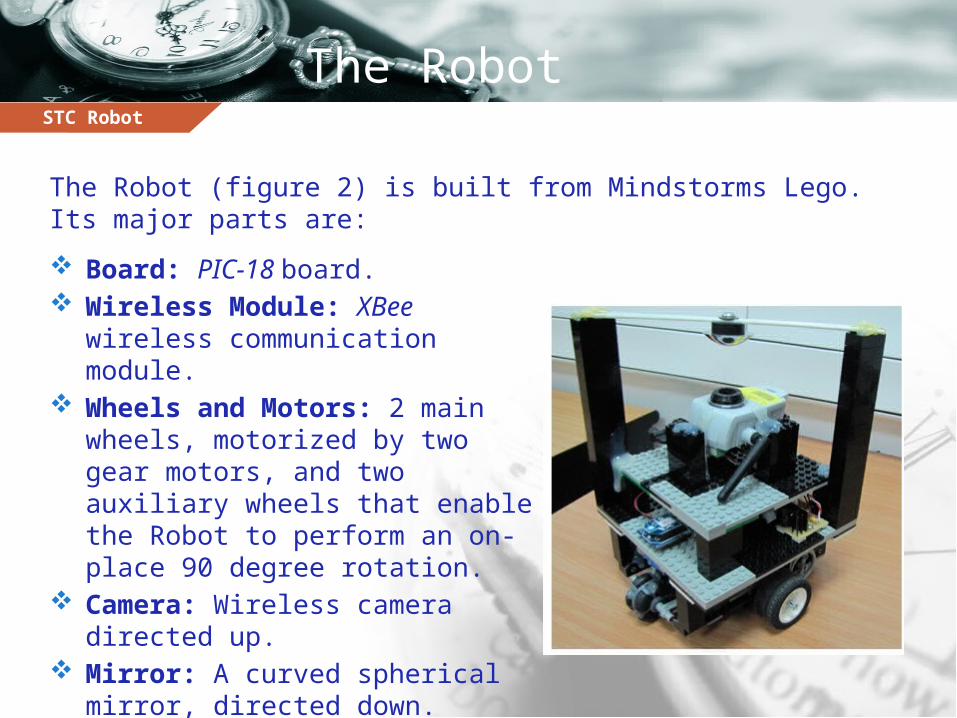
Board: PIC-18 board. Wireless Module: XBee
wireless communication module. Wheels and Motors: 2 main
wheels, motorized by two gear motors, and two auxiliary wheels that enable the Robot to perform an on-place 90 degree rotation.
Camera: Wireless camera directed up.
Mirror: A curved spherical mirror, directed down.
The Robot (figure 2) is built from Mindstorms Lego. Its major parts are:
STC Robot
The Image
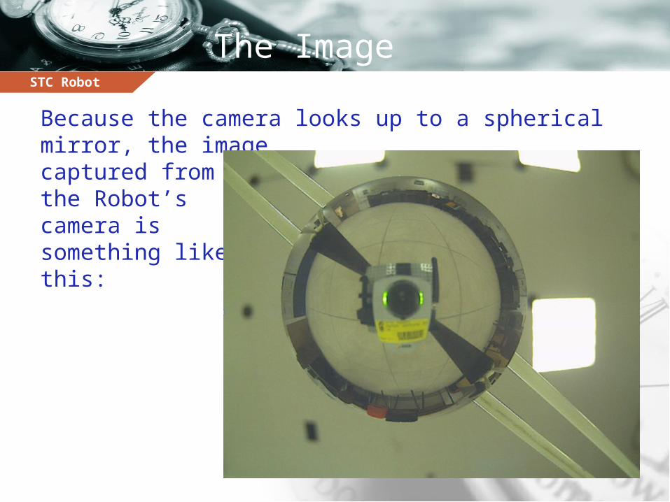
Because the camera looks up to a spherical mirror, the image captured from the Robot’s camera is something like this:
STC Robot
After the Transformation
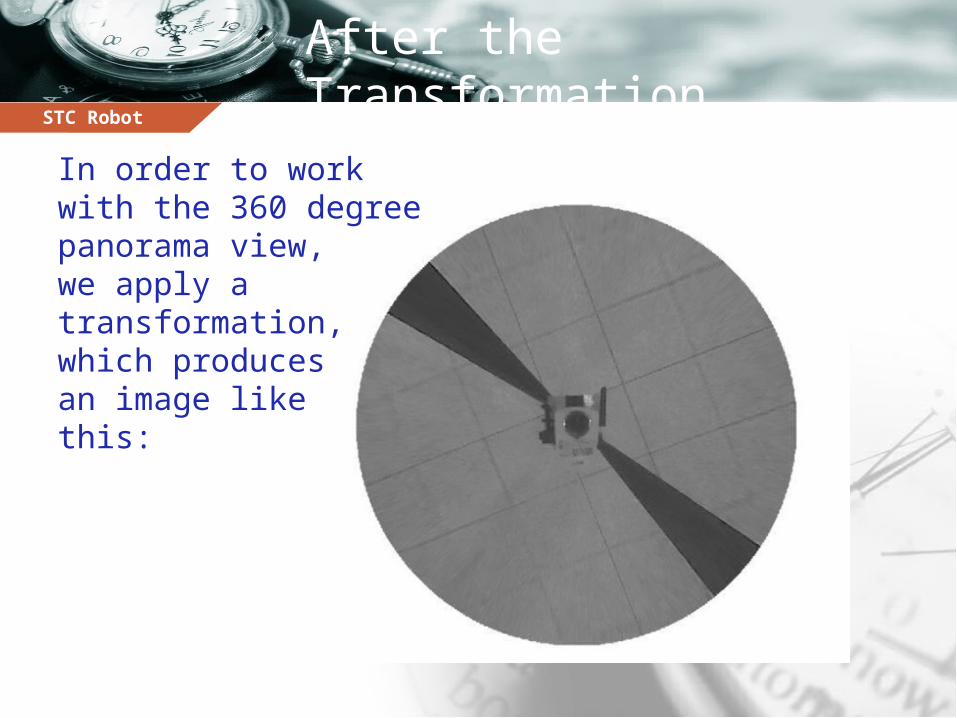
In order to work with the 360 degreepanorama view, we apply a transformation, which produces an image like this:
STC Robot
The Transformation idea
Comparing the location of a single pixel in the two images (the curved image and the normal transformed image):1. Both are in the same axis that connects the pixel with
the camera’s center.
2. The pixel in the curved image is closer to the camera.
So what we need to do is to calculate the ratio between its distances of the camera lens in the two pictures.
STC Robot
Angle Detection
Why do we need it? Calibration (Lego and battery issues). Connectivity issues (explained later).
What to do? Calculate the slope of the black lines between the
ground cells.
STC Robot
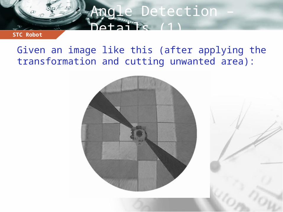
Angle Detection – Details (1)
Given an image like this (after applying the transformation and cutting unwanted area):
STC Robot
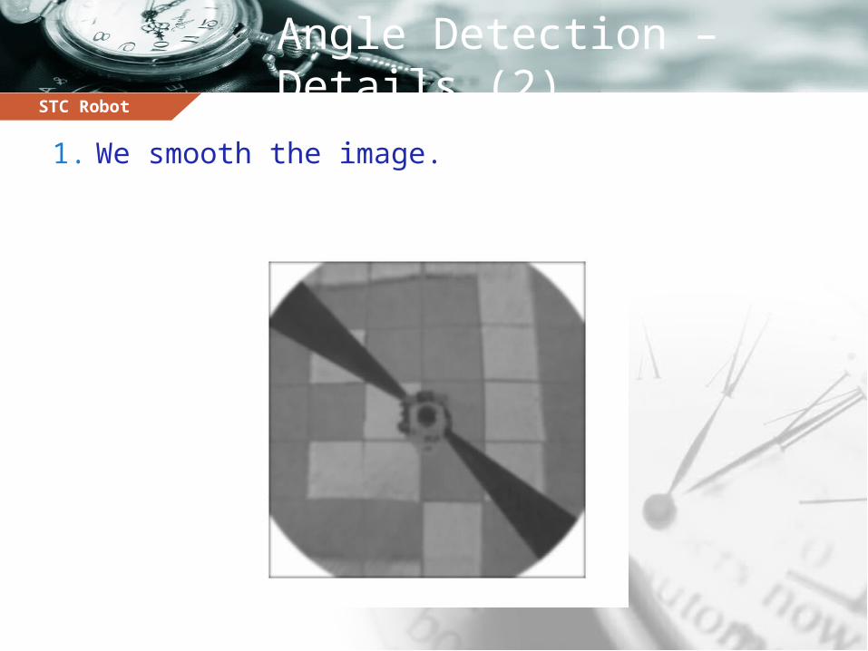
Angle Detection – Details (2)
1. We smooth the image.
STC Robot
Angle Detection – Details (3)
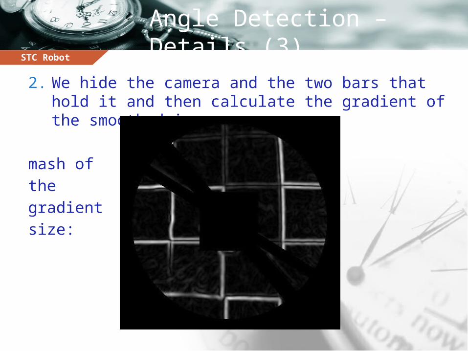
2. We hide the camera and the two bars that hold it and then calculate the gradient of the smoothed image.
mash of the gradient size:
STC Robot
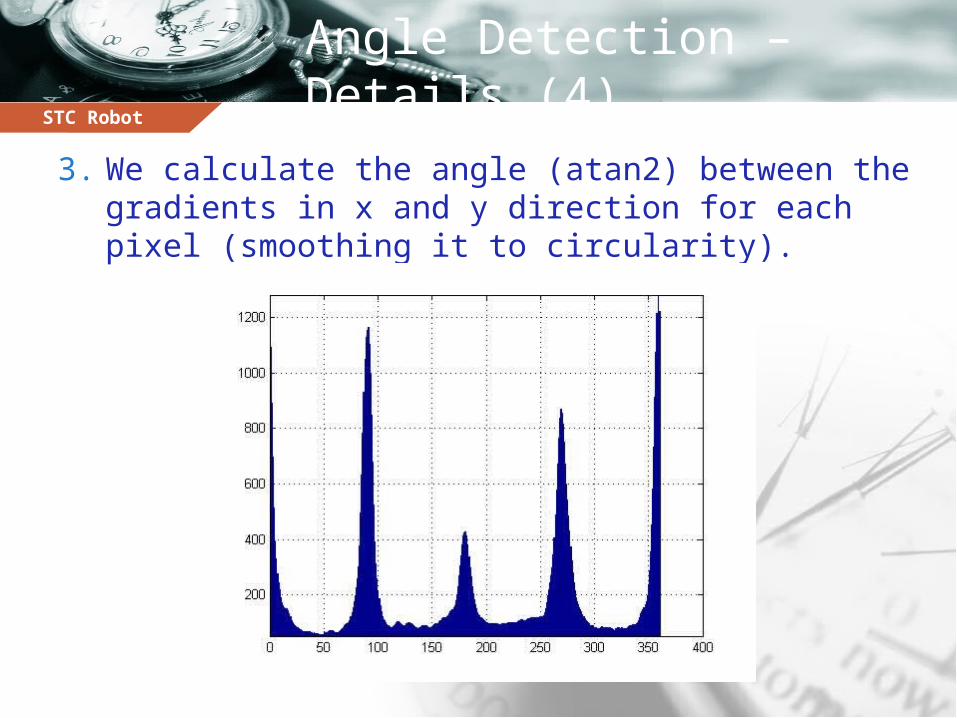
Angle Detection – Details (4)
3. We calculate the angle (atan2) between the gradients in x and y direction for each pixel (smoothing it to circularity).
STC Robot
Angle Detection – Details (5)
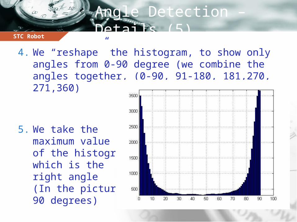
4. We “reshape” the histogram, to show only angles from 0-90 degree (we combine the angles together, (0-90, 91-180, 181,270, 271,360)
5. We take the maximum value of the histogram, which is the right angle (In the picture 90 degrees)
STC Robot
Rotation time calibration
Initial 90-degree rotation time = T. After sending the robot a command to rotate for
time T: We detect the actual angle the robot rotated in. Let’s say we got instead of 90. So next time, we
should give the robot a timestamp of .
STC Robot
Obstacles Detection
Obstacles are modeled as completely white cells. Regular cells (path) are gray. Summing up the values of all the pixels in an
obstacle cell should give us a higher value than the sum of all the values of the pixels of a regular free cell.
STC Robot
Connectivity Issues (1)
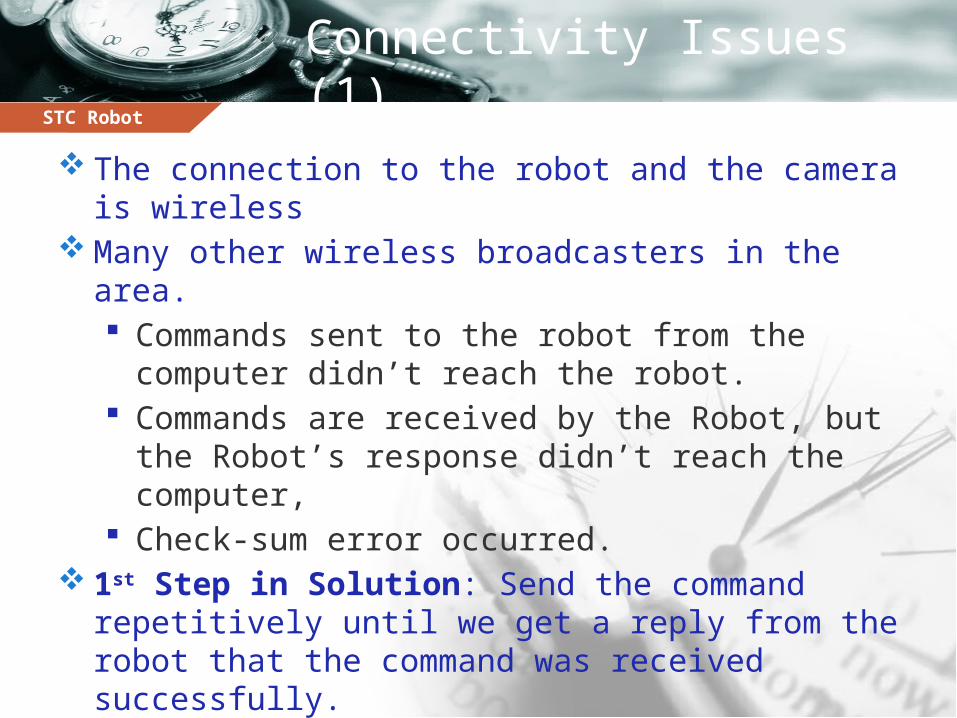
The connection to the robot and the camera is wireless
Many other wireless broadcasters in the area. Commands sent to the robot from the computer didn’t
reach the robot. Commands are received by the Robot, but the Robot’s
response didn’t reach the computer, Check-sum error occurred.
1st Step in Solution: Send the command repetitively until we get a reply from the robot that the command was received successfully.
STC Robot
Connectivity Issues (2)
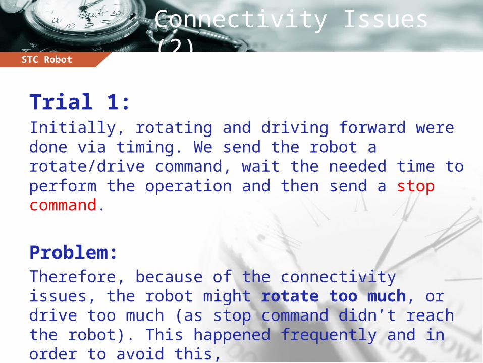
Trial 1:Initially, rotating and driving forward were done via timing. We send the robot a rotate/drive command, wait the needed time to perform the operation and then send a stop command.
Problem: Therefore, because of the connectivity issues, the robot might rotate too much, or drive too much (as stop command didn’t reach the robot). This happened frequently and in order to avoid this,
STC Robot
Connectivity Issues (3)
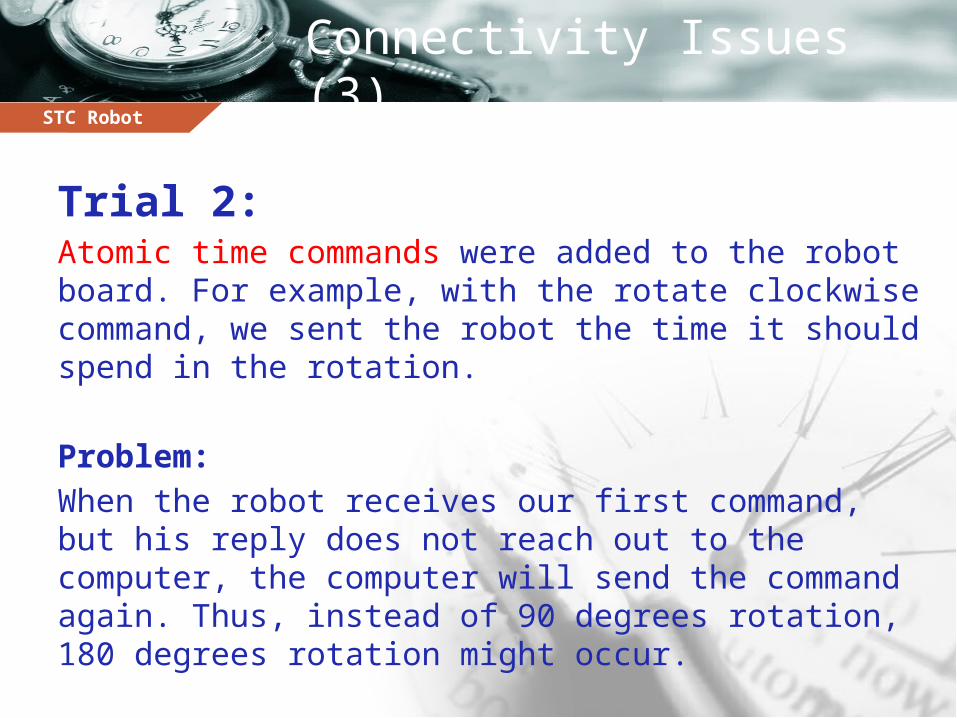
Trial 2:Atomic time commands were added to the robot board. For example, with the rotate clockwise command, we sent the robot the time it should spend in the rotation.
Problem: When the robot receives our first command, but his reply does not reach out to the computer, the computer will send the command again. Thus, instead of 90 degrees rotation, 180 degrees rotation might occur.
STC Robot
Connectivity Issues (4)
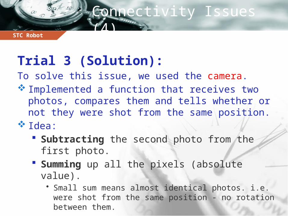
Trial 3 (Solution):To solve this issue, we used the camera. Implemented a function that receives two photos,
compares them and tells whether or not they were shot from the same position.
Idea: Subtracting the second photo from the first photo. Summing up all the pixels (absolute value).
• Small sum means almost identical photos. i.e. were shot from the same position - no rotation between them.
STC Robot
Optimally Covering an Unknown Indoor Environment (OCUIE)
http://www.youtube.com/watch?v=ZewJhJ27mRk
MOVIE
STC Robot
What’s next?
Optimally Covering an Unknown Indoor Environment Using O(1) Memory.The current implementation of the STC algorithm (the covering algorithm) saves each sub-cell visited by the robot and its parent cell, so it uses memory (where n is the number of cells).
STC Robot
Goal
Doing the same algorithm using memory.
Using the glowing floor the robot leaves “traces”. No need to save the visited cells.
New challenges: Using the camera we use the “traces” to determine
where to head next (different implementation of the algorithm).
We don’t have the lines between the cells which used to detect the angle and the robot’ place.

STCRobot
Majd Srour, Anis AbboudUnder the supervision of: Yotam Elor and Prof. Alfred Bruckstein

STC Robot
BACKUP
BACKUP
STC Robot
The On-line STC Algorithm
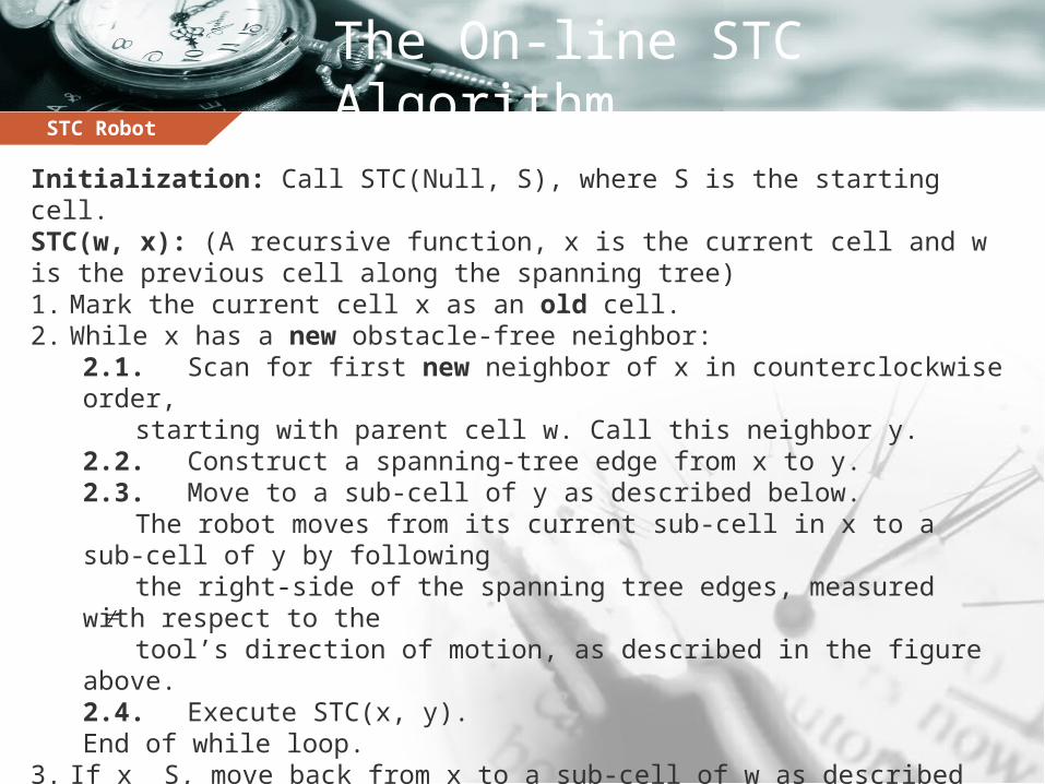
Initialization: Call STC(Null, S), where S is the starting cell.STC(w, x): (A recursive function, x is the current cell and w is the previous cell along the spanning tree)1. Mark the current cell x as an old cell.2. While x has a new obstacle-free neighbor:
2.1. Scan for first new neighbor of x in counterclockwise order, starting with parent cell w. Call this neighbor y.
2.2. Construct a spanning-tree edge from x to y.2.3. Move to a sub-cell of y as described below.
The robot moves from its current sub-cell in x to a sub-cell of y by following
the right-side of the spanning tree edges, measured with respect to thetool’s direction of motion, as described in the figure above.
2.4. Execute STC(x, y).End of while loop.
3. If x S, move back from x to a sub-cell of w as described below.When the covering tool returns to a parent cell w, it again moves through sub-cells that lie on the right-side of the spanning-tree edge connecting x with w, as shown in the figure above.
4. Return. (End of STC(w, x).)


![STATUL MAJOR AL FOR}ELOR TERESTRE REVISTà DE · PDF filerevista for]elor terestre revistà de teorie militarà editatà de statul major al for}elor terestre fondatà În 1954 sub](https://img.pdfslide.us/doc/110x75/5a78ec047f8b9aa17b8ea71a/statul-major-al-forelor-terestre-revist-de-forelor-terestre-revist-de-teorie.jpg)


![revista for]elor terestre](https://img.pdfslide.us/doc/110x75/588c5ce51a28ab82218b61a2/revista-forelor-terestre.jpg)