Embed Size (px)
Citation preview
QPSK Acoustic Software Radio
Orr Srour & Naftali ZonUnder the supervision of
Ami Wiesel
The problem
RF Communication systems, and especially MIMO communication systems are:
expensive have long development time require wide technological knowledge
The need
Besides their public use, in the academic world communication systems are needed for vary of reasons, for example – new algorithms testing.
In many cases, making a real communication system is simply unreasonable.
The goal
Real time communication system. Rapid development Easy to construct, manipulate and
upgrade Modular
The solution
Using ACOUSTIC waves instead of electromagnetic.
Fully software implemented - Simple ordinary computer is enough
We will use the computer as our processing unit (we use Matlab-Simulink), and ordinary speakers and microphones as our antennas.
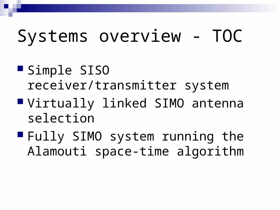
Systems overview - TOC
Simple SISO receiver/transmitter system Virtually linked SIMO antenna selection Fully SIMO system running the Alamouti
space-time algorithm
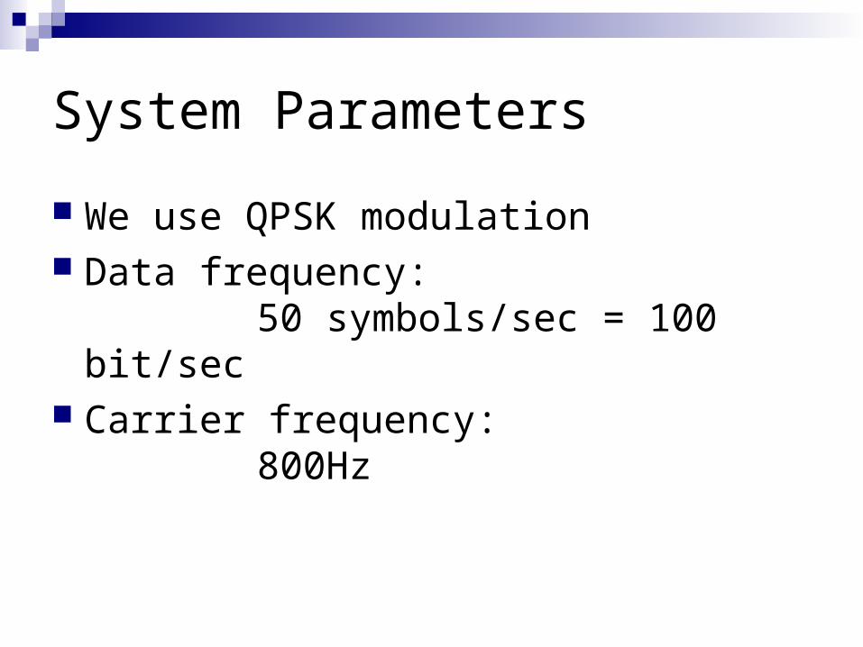
System Parameters
We use QPSK modulation Data frequency:
50 symbols/sec = 100 bit/sec Carrier frequency:
800Hz
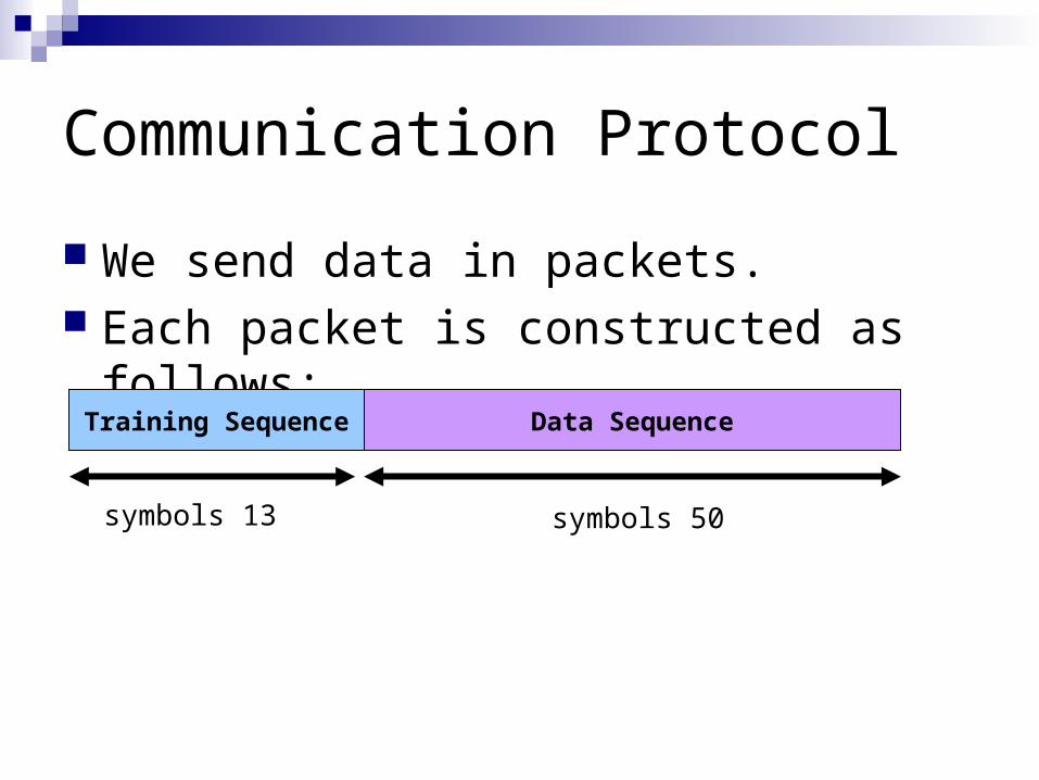
Communication Protocol
We send data in packets. Each packet is constructed as follows:
Training Sequence Data Sequence
13 symbols 50 symbols
Training Packets
The training sequence are constant predefined series of symbols.
They allow us to distinguish actual data packet from random noise.
They allow us to estimate the propagation channel and reconstruct the data.
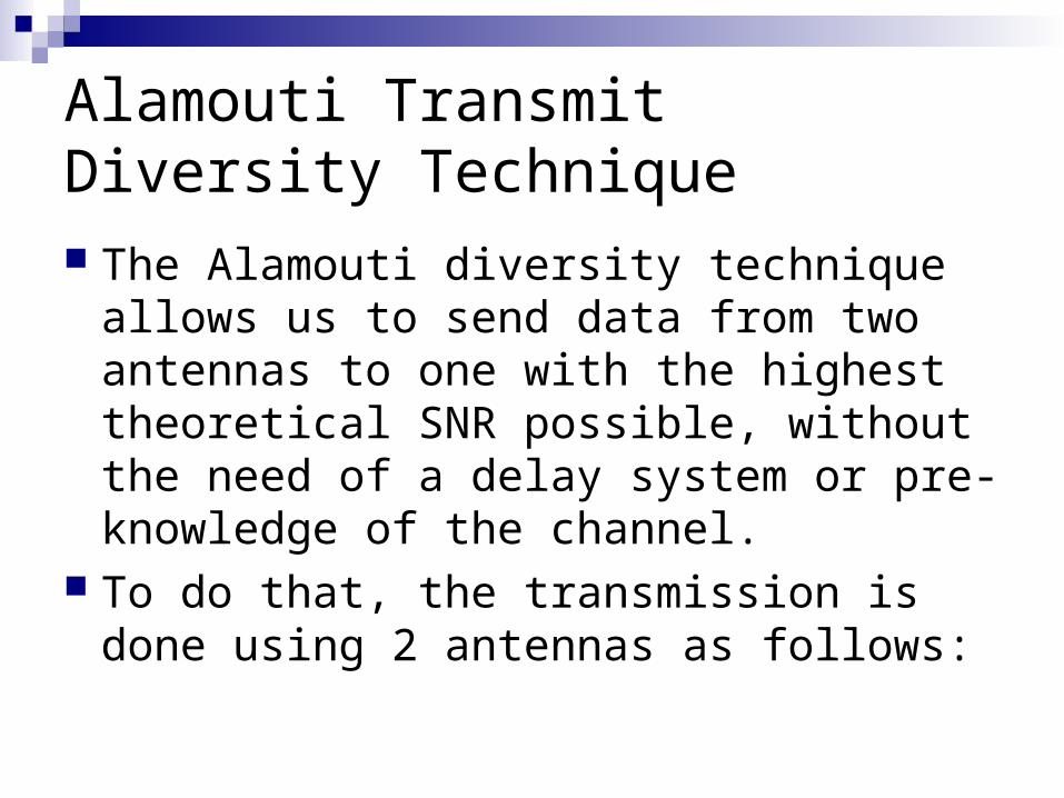
Alamouti Transmit Diversity Technique The Alamouti diversity technique allows us
to send data from two antennas to one with the highest theoretical SNR possible, without the need of a delay system or pre-knowledge of the channel.
To do that, the transmission is done using 2 antennas as follows:
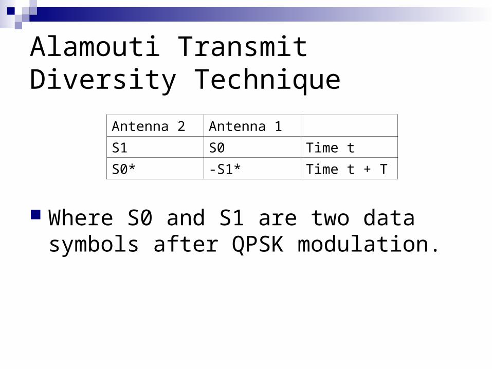
Alamouti Transmit Diversity Technique
Where S0 and S1 are two data symbols after QPSK modulation.
Antenna 1Antenna 2
Time tS0S1
Time t + T-S1*S0*
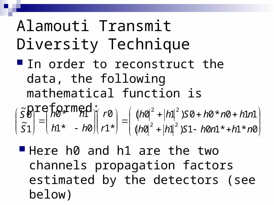
Alamouti Transmit Diversity Technique In order to reconstruct the data, the
following mathematical function is preformed:
0*1*101)10(
110*00)10(
*1
0
0*1
1*0
1~0
~
22
22
nhnhShh
nhnhShh
r
r
hh
hh
S
S
Here h0 and h1 are the two channels propagation factors estimated by the detectors (see below)
“Down to Top” overview – our basic building blocks
We will now introduce our basic building blocks, which will later be shown inside the different type of systems.
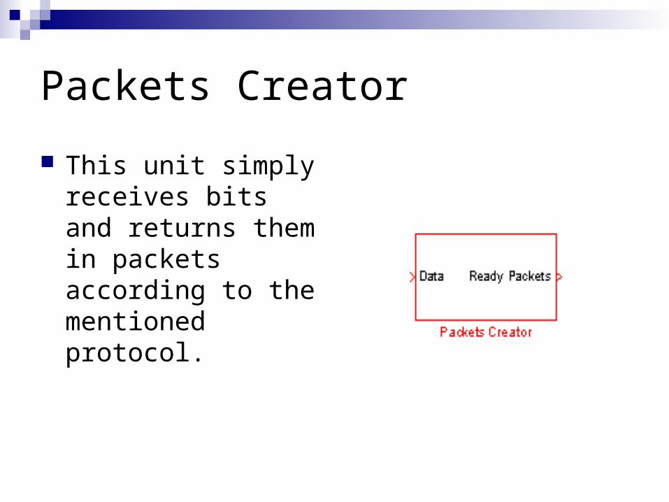
Packets Creator
This unit simply receives bits and returns them in packets according to the mentioned protocol.
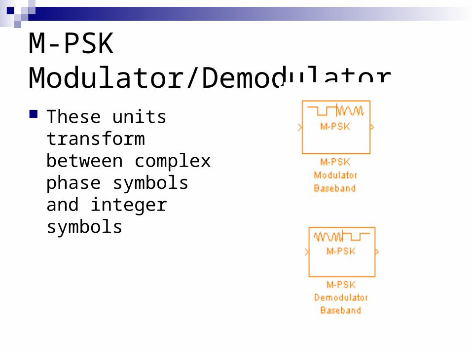
M-PSK Modulator/Demodulator
These units transform between complex phase symbols and integer symbols
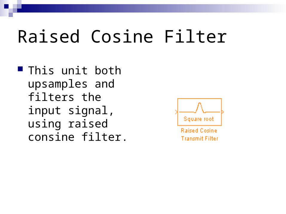
Raised Cosine Filter
This unit both upsamples and filters the input signal, using raised consine filter.
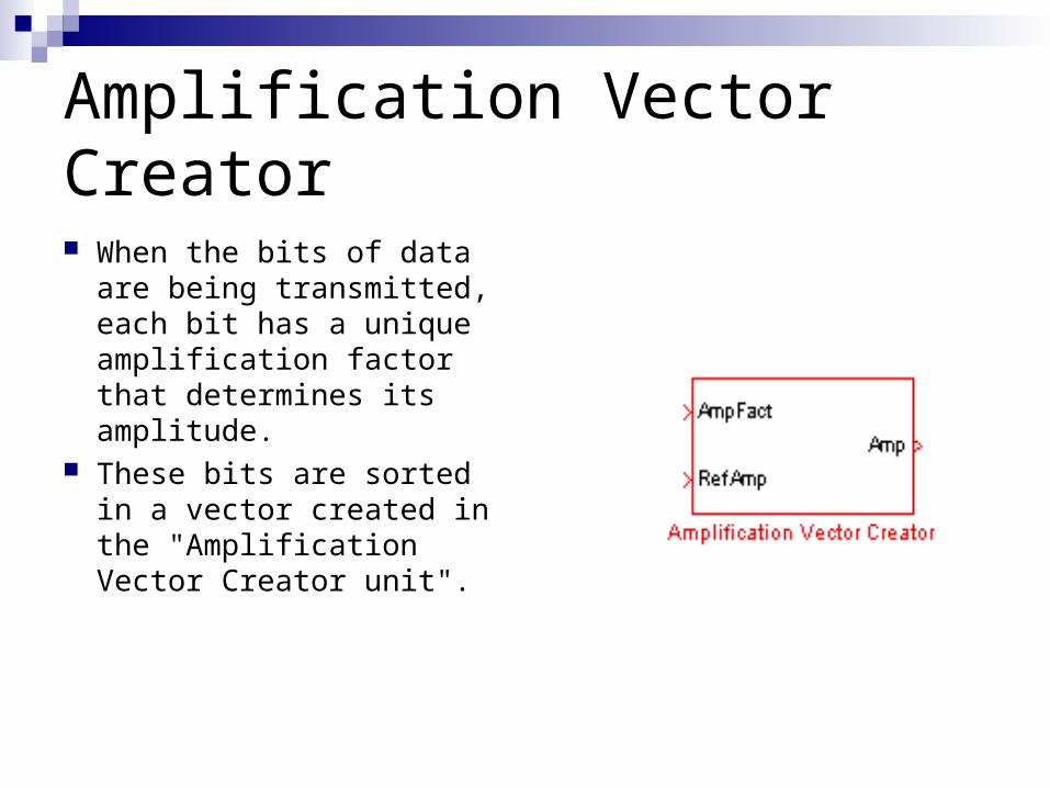
Amplification Vector Creator
When the bits of data are being transmitted, each bit has a unique amplification factor that determines its amplitude.
These bits are sorted in a vector created in the "Amplification Vector Creator unit".
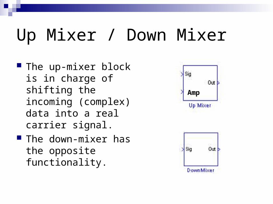
Up Mixer / Down Mixer
The up-mixer block is in charge of shifting the incoming (complex) data into a real carrier signal.
The down-mixer has the opposite functionality.
Amp
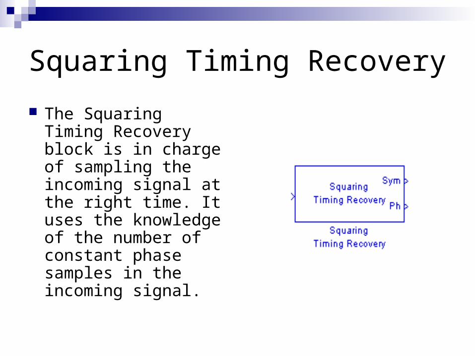
Squaring Timing Recovery
The Squaring Timing Recovery block is in charge of sampling the incoming signal at the right time. It uses the knowledge of the number of constant phase samples in the incoming signal.
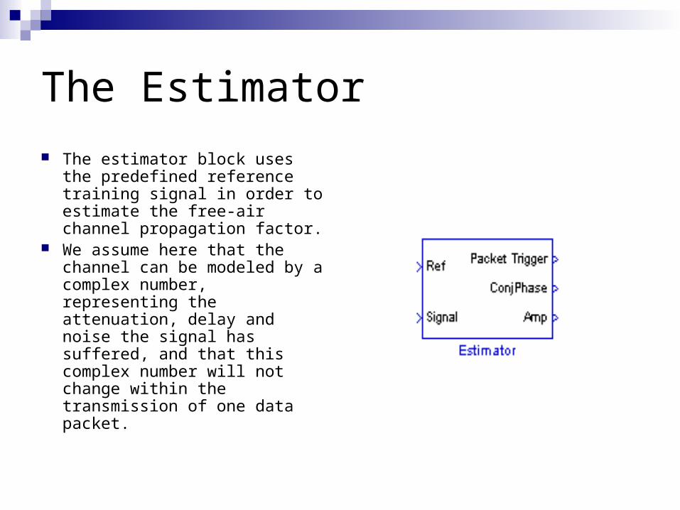
The Estimator
The estimator block uses the predefined reference training signal in order to estimate the free-air channel propagation factor.
We assume here that the channel can be modeled by a complex number, representing the attenuation, delay and noise the signal has suffered, and that this complex number will not change within the transmission of one data packet.
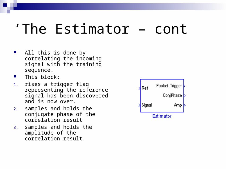
The Estimator – cont’
All this is done by correlating the incoming signal with the training sequence.
This block:1. rises a trigger flag
representing the reference signal has been discovered and is now over.
2. samples and holds the conjugate phase of the correlation result
3. samples and holds the amplitude of the correlation result.
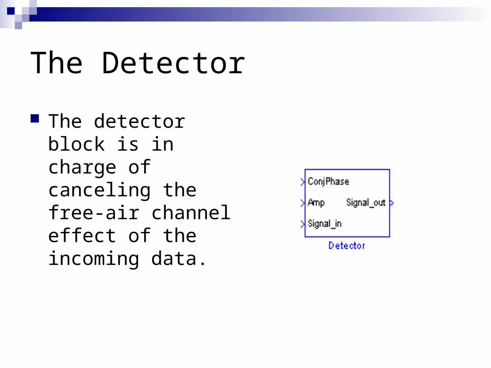
The Detector
The detector block is in charge of canceling the free-air channel effect of the incoming data.
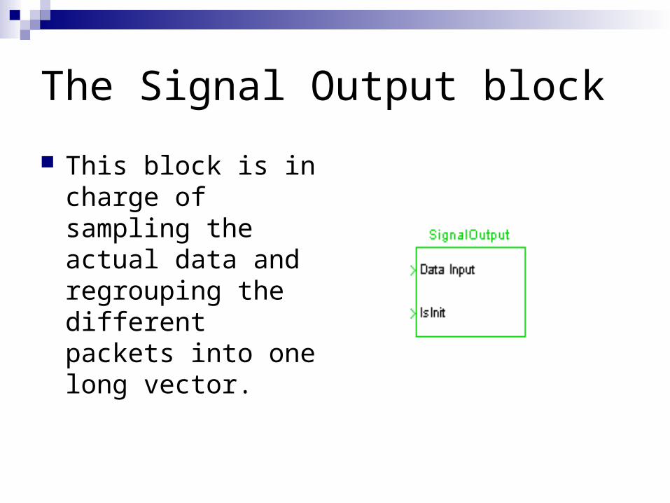
The Signal Output block
This block is in charge of sampling the actual data and regrouping the different packets into one long vector.
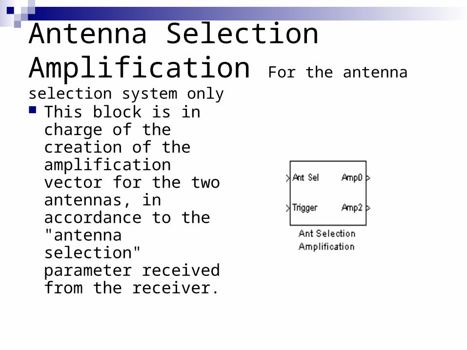
Antenna Selection Amplification For the antenna selection system only
This block is in charge of the creation of the amplification vector for the two antennas, in accordance to the "antenna selection" parameter received from the receiver.
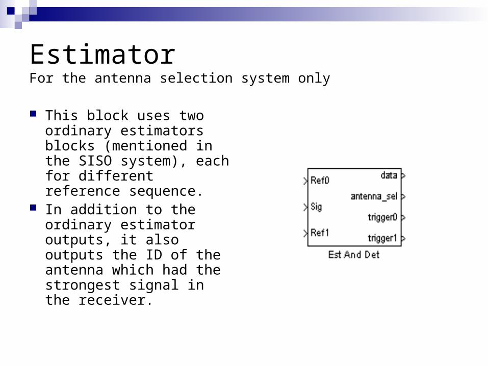
EstimatorFor the antenna selection system only
This block uses two ordinary estimators blocks (mentioned in the SISO system), each for different reference sequence.
In addition to the ordinary estimator outputs, it also outputs the ID of the antenna which had the strongest signal in the receiver.
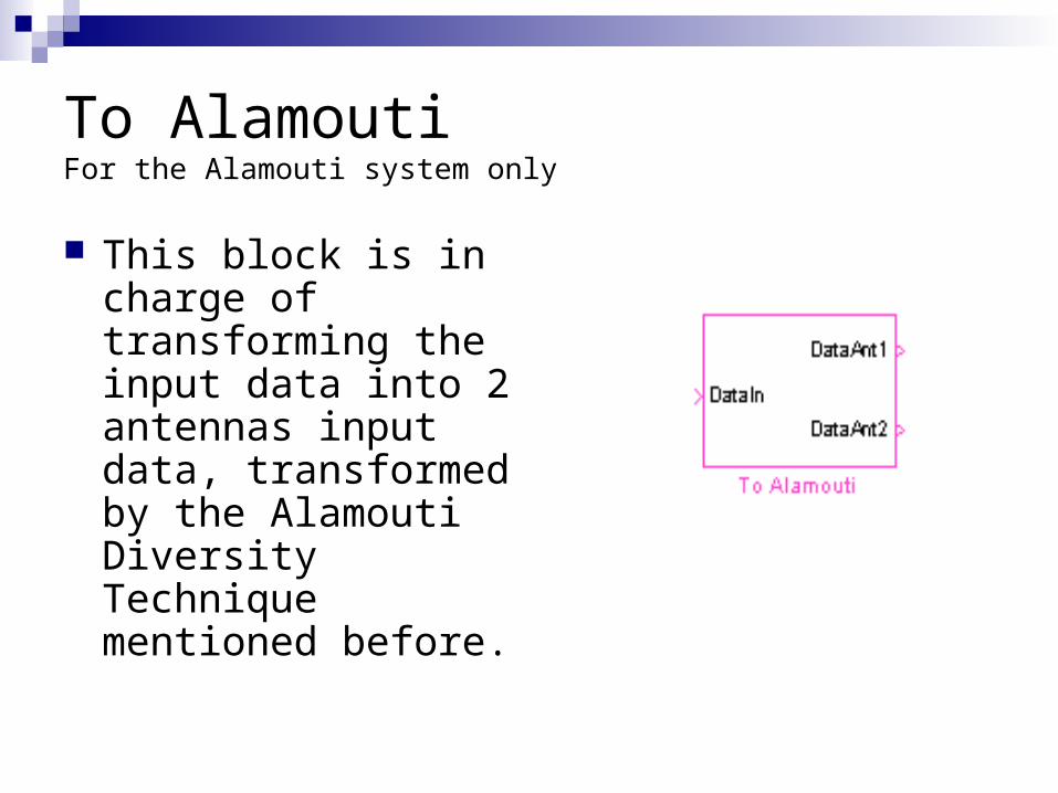
To AlamoutiFor the Alamouti system only
This block is in charge of transforming the input data into 2 antennas input data, transformed by the Alamouti Diversity Technique mentioned before.
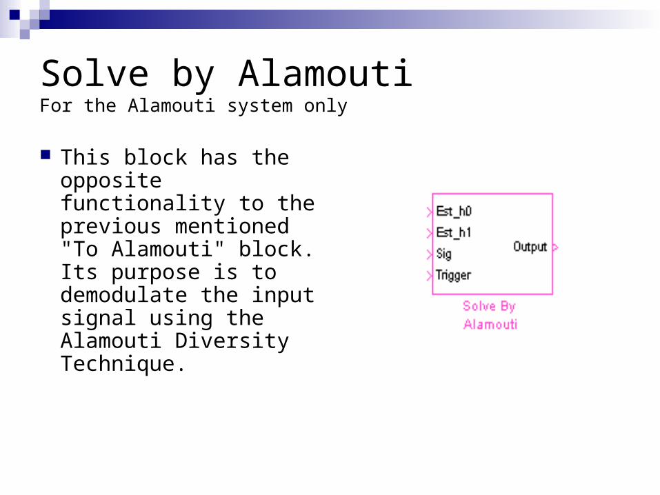
Solve by AlamoutiFor the Alamouti system only
This block has the opposite functionality to the previous mentioned "To Alamouti" block. Its purpose is to demodulate the input signal using the Alamouti Diversity Technique.
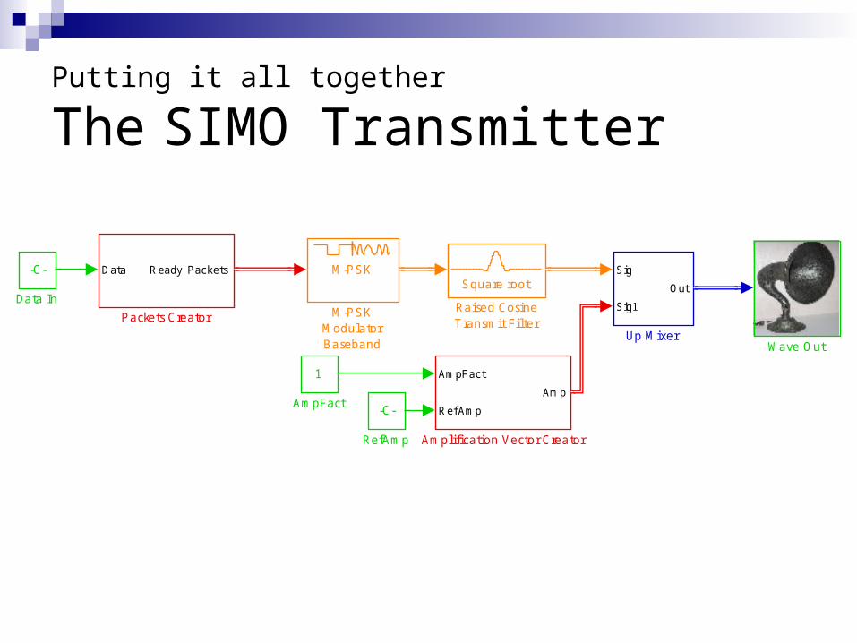
Putting it all together
The SIMO Transmitter
Wave Out
Sig
Sig1
Out
Up Mixer
-C-
RefAmp
Square root
Raised CosineTransmit Fi l ter
Data Ready Packets
Packets Creator
M-PSK
M-PSKModulatorBaseband
-C-
Data In
AmpFact
Ref Amp
Amp
Ampli fication Vector Creator
1
AmpFact
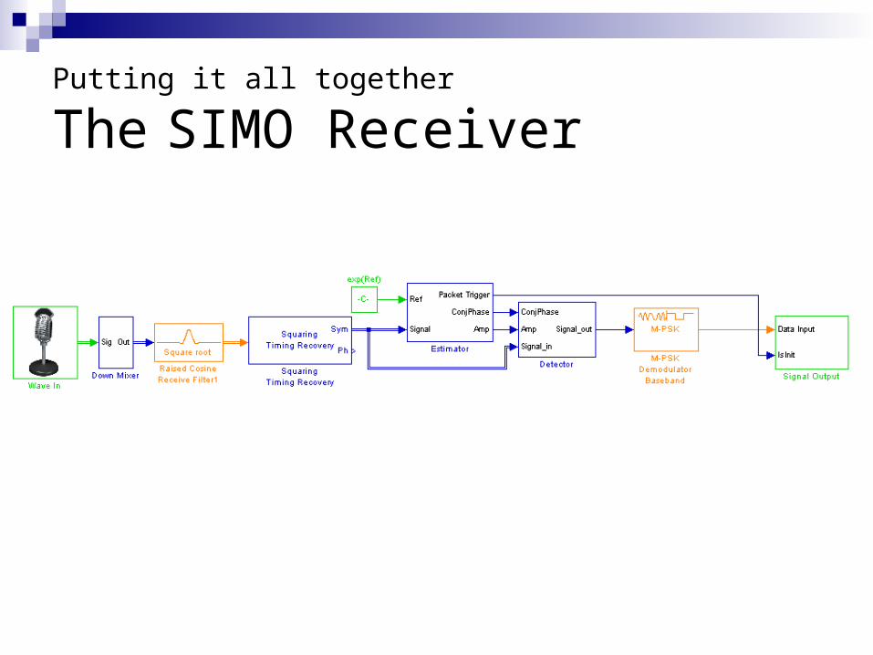
Putting it all together
The SIMO Receiver

Putting it all together
The SIMO Receiver
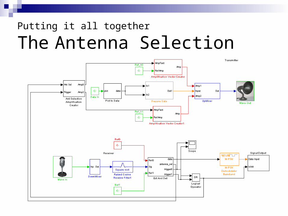
Putting it all together
The Antenna Selection

Putting it all together
The Antenna Selection
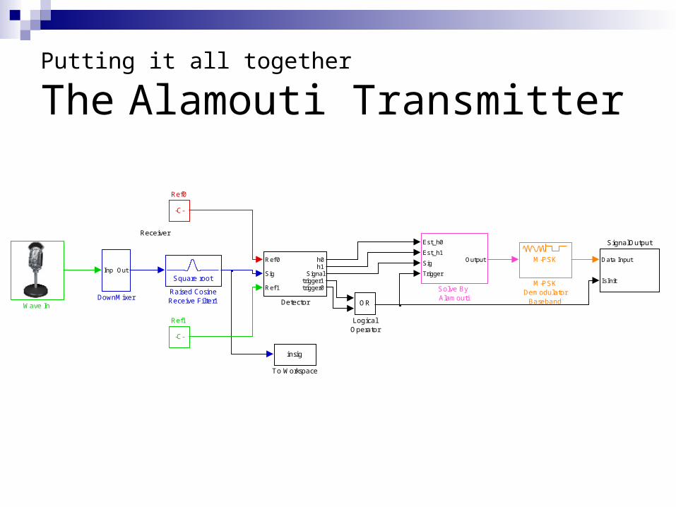
Putting it all together
The Alamouti Transmitter
Receiver
Wave In
insig
To Workspace
Est_h0
Est_h1
Sig
Trigger
Output
Solve By Alamouti
Data Input
IsInit
SignalOutput
-C-
Ref1
-C-
Ref0
Square root
Raised CosineReceive Filter1
M-PSK
M-PSKDemodulator
BasebandOR
LogicalOperator
Inp Out
DownMixer
Ref 0
Sig
Ref 1
h0h1
Signaltrigger1trigger0
Detector
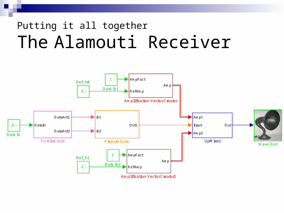
Putting it all together
The Alamouti Receiver
Wave Out
Amp1
Input
Amp2
Out
UpMixer
DataIn
DataAnt1
DataAnt2
To Alamouti
-C-
Ref_h1
-C-
Ref_h0
In1
In2
Out1
Prepare Data
1
Data In2
1
Data In1
-C-
Data In
AmpFact
Ref Amp
Amp
Amplification Vector Creator1
AmpFact
Ref Amp
Amp
Amplification Vector Creator

Putting it all together
The Alamouti Receiver
Future Applications
short-range communication system on a single chip (using ultrasound waves)
submarine communication systems implementation of MIMO sonar system

Questions