Embed Size (px)
Citation preview
STANDARD SPECIFICATIONS
AND DRAWINGS
CALL (925) 625-3798
FOR ASSISTANCE OR VISIT
WWW.DIABLOWATER.ORG
DECEMBER 2013
1. Section Index
1 of 2
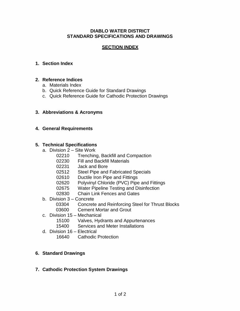
DIABLO WATER DISTRICT STANDARD SPECIFICATIONS AND DRAWINGS
SECTION INDEX
1. Section Index
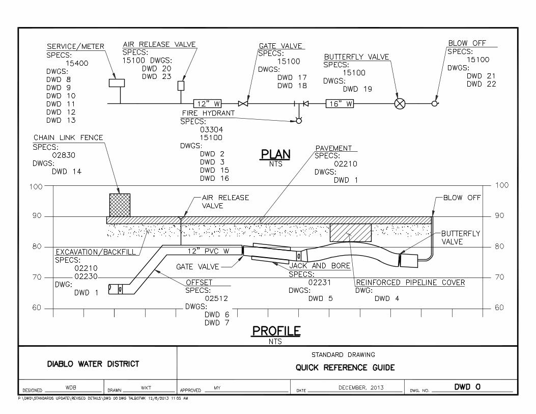
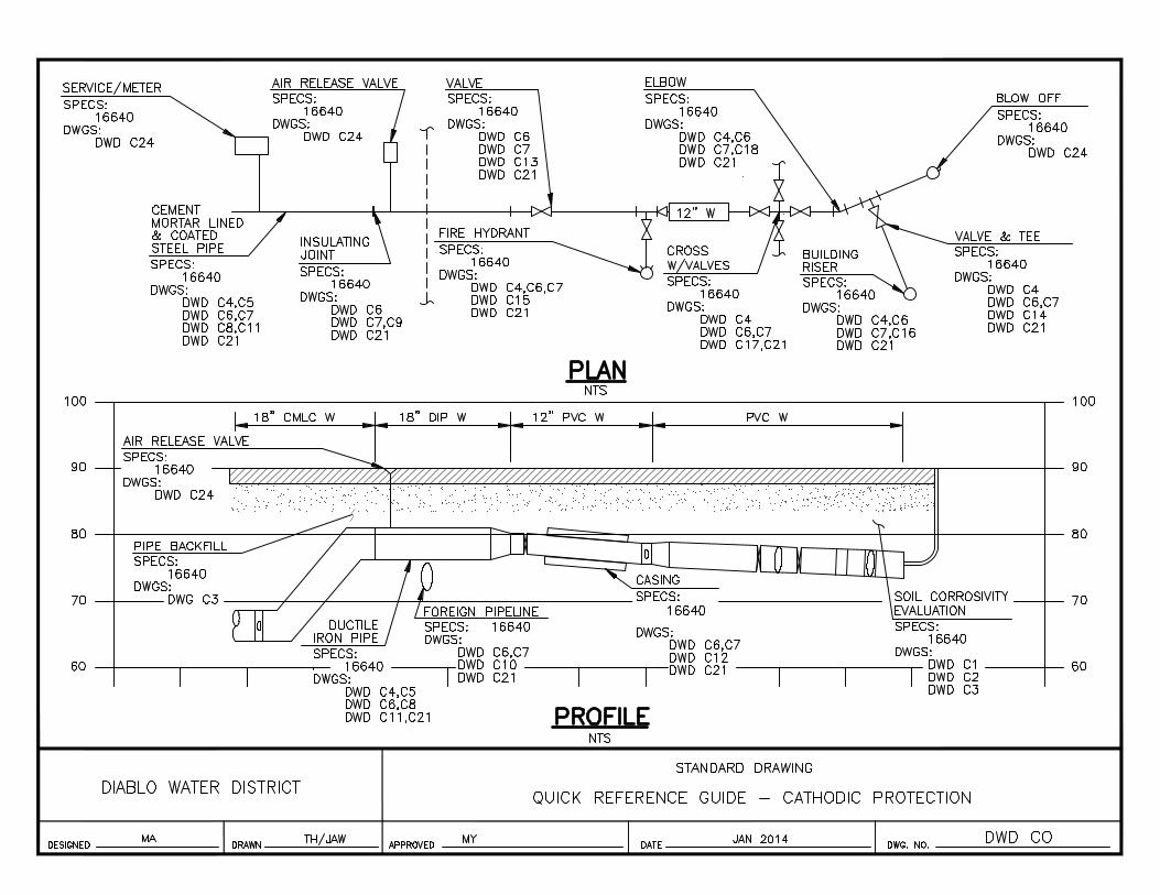
2. Reference Indices a. Materials Index b. Quick Reference Guide for Standard Drawings c. Quick Reference Guide for Cathodic Protection Drawings
3. Abbreviations & Acronyms
4. General Requirements
5. Technical Specifications a. Division 2 – Site Work
02210 Trenching, Backfill and Compaction 02230 Fill and Backfill Materials 02231 Jack and Bore 02512 Steel Pipe and Fabricated Specials 02610 Ductile Iron Pipe and Fittings 02620 Polyvinyl Chloride (PVC) Pipe and Fittings 02675 Water Pipeline Testing and Disinfection 02830 Chain Link Fences and Gates
b. Division 3 – Concrete 03304 Concrete and Reinforcing Steel for Thrust Blocks 03600 Cement Mortar and Grout
c. Division 15 – Mechanical 15100 Valves, Hydrants and Appurtenances 15400 Services and Meter Installations
d. Division 16 – Electrical 16640 Cathodic Protection
6. Standard Drawings
7. Cathodic Protection System Drawings
2 of 2
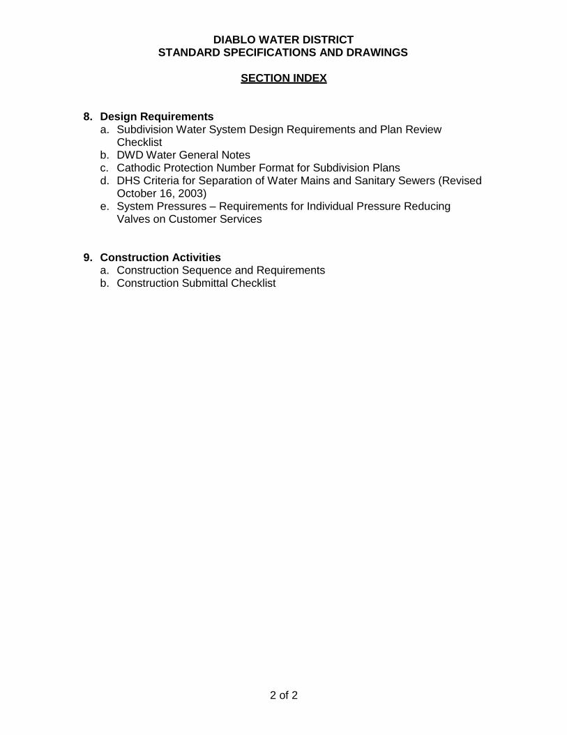
DIABLO WATER DISTRICT STANDARD SPECIFICATIONS AND DRAWINGS
SECTION INDEX
8. Design Requirements
a. Subdivision Water System Design Requirements and Plan Review Checklist
b. DWD Water General Notes c. Cathodic Protection Number Format for Subdivision Plans d. DHS Criteria for Separation of Water Mains and Sanitary Sewers (Revised
October 16, 2003) e. System Pressures – Requirements for Individual Pressure Reducing
Valves on Customer Services
9. Construction Activities a. Construction Sequence and Requirements b. Construction Submittal Checklist
2. Reference Indices

Diablo Water District Print Date: December 2013 Standard Specifications
DIABLO WATER DISTRICT STANDARD SPECIFICATIONS AND DRAWINGS
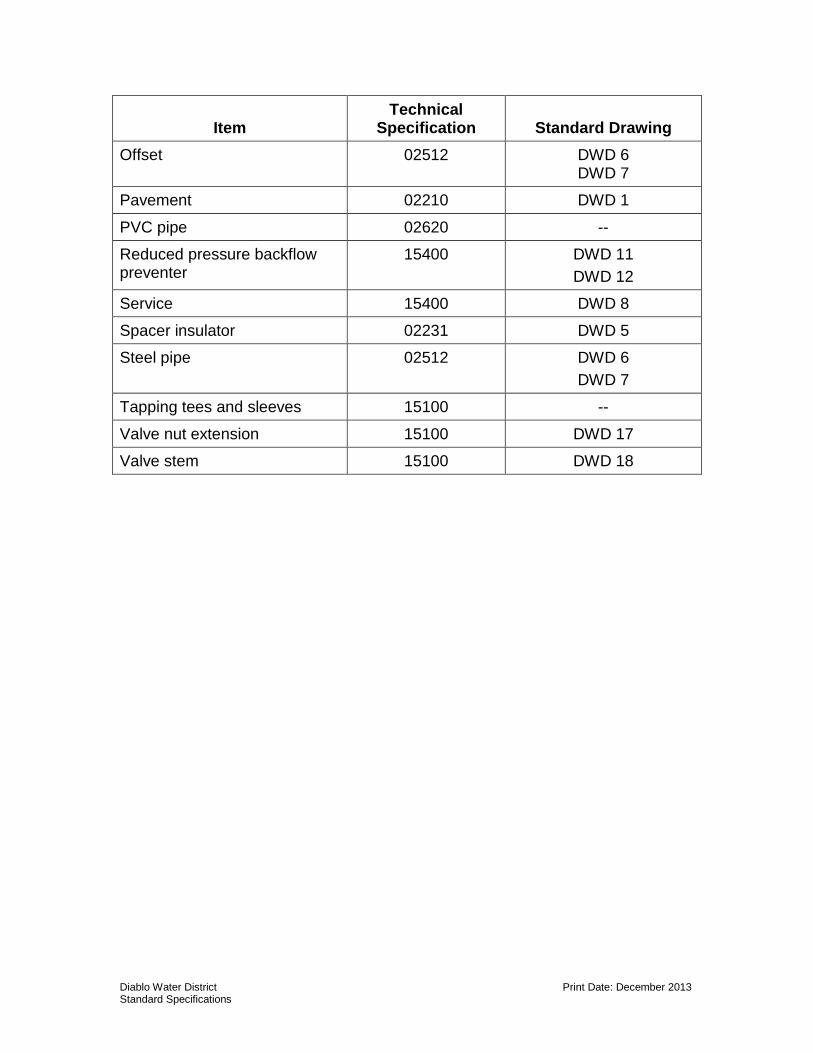
MATERIALS INDEX
Item Technical
Specification Standard Drawing
Air release valve 15100 DWD 20
DWD 23 (alternate)
Backfill 02230 DWD 1
Ball valve 15100 --
Blow off 15100 DWD 21 DWD 22
Bollard -- DWD 24
Butterfly valve 15100 DWD 19
Cathodic protection 16640 DWD C1 through DWD C29
Chain link fence 02830 DWD 14
Corporation stop 15400 DWD 8
Double check valve 15400 DWD 10
Double detector check valve 15400 DWD 13
Ductile iron pipe 02610 --
Fire hydrant 15100 DWD 15 DWD 16
Flange coupling adapter 15100 --
Gate valve 15100 DWD 15 DWD 17 DWD 18
Insulating fittings 15100 --
Mechanical coupling 15100 --
Meter 15400 DWD 8 DWD 9
Meter box 15400 DWD 8 DWD 9
Diablo Water District Print Date: December 2013 Standard Specifications
Item Technical
Specification Standard Drawing
Offset 02512 DWD 6 DWD 7
Pavement 02210 DWD 1
PVC pipe 02620 --
Reduced pressure backflow preventer
15400 DWD 11
DWD 12
Service 15400 DWD 8
Spacer insulator 02231 DWD 5
Steel pipe 02512 DWD 6
DWD 7
Tapping tees and sleeves 15100 --
Valve nut extension 15100 DWD 17
Valve stem 15100 DWD 18

3. Abbreviations & Acronyms
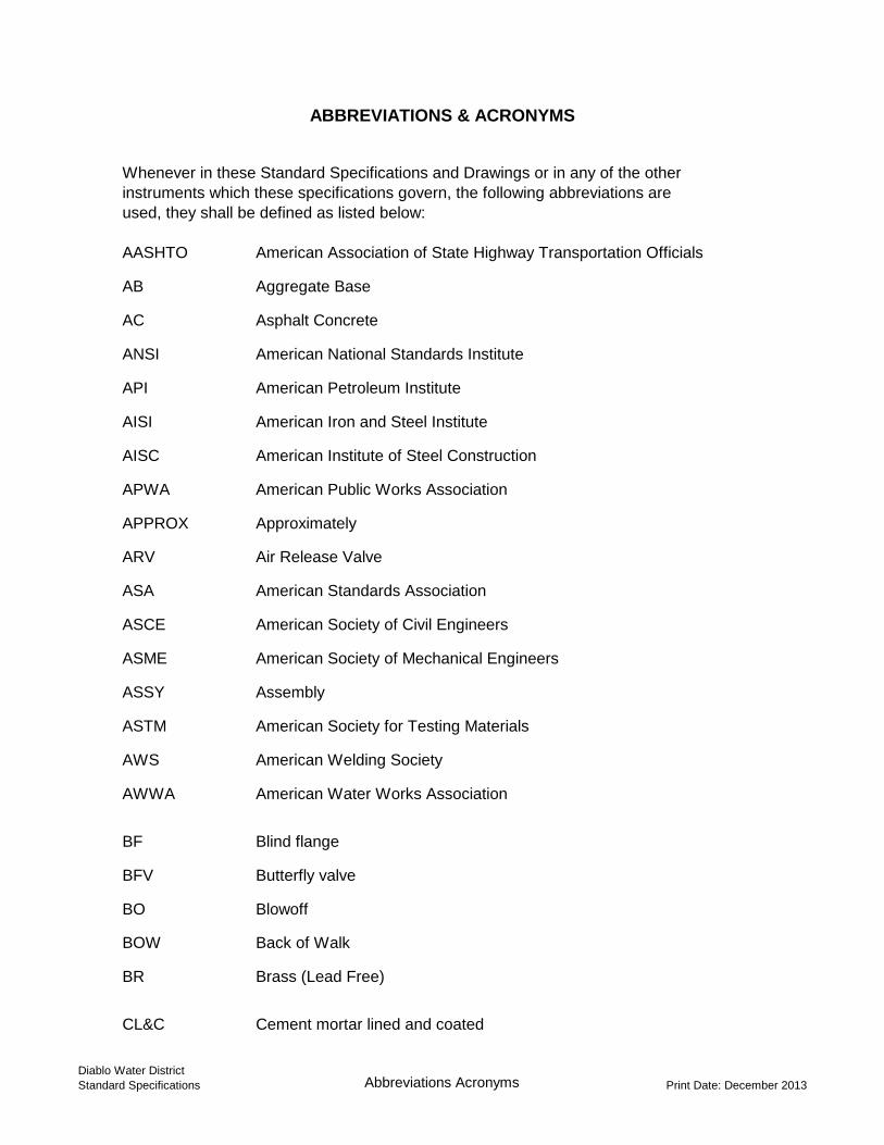
ABBREVIATIONS & ACRONYMS
Whenever in these Standard Specifications and Drawings or in any of the other
instruments which these specifications govern, the following abbreviations are
used, they shall be defined as listed below:
AASHTO American Association of State Highway Transportation Officials
AB Aggregate Base
AC Asphalt Concrete
ANSI American National Standards Institute
API American Petroleum Institute
AISI American Iron and Steel Institute
AISC American Institute of Steel Construction
APWA American Public Works Association
APPROX Approximately
ARV Air Release Valve
ASA American Standards Association
ASCE American Society of Civil Engineers
ASME American Society of Mechanical Engineers
ASSY Assembly
ASTM American Society for Testing Materials
AWS American Welding Society
AWWA American Water Works Association
BF Blind flange
BFV Butterfly valve
BO Blowoff
BOW Back of Walk
BR Brass (Lead Free)
CL&C Cement mortar lined and coated
Diablo Water District
Standard Specifications Abbreviations Acronyms Print Date: December 2013
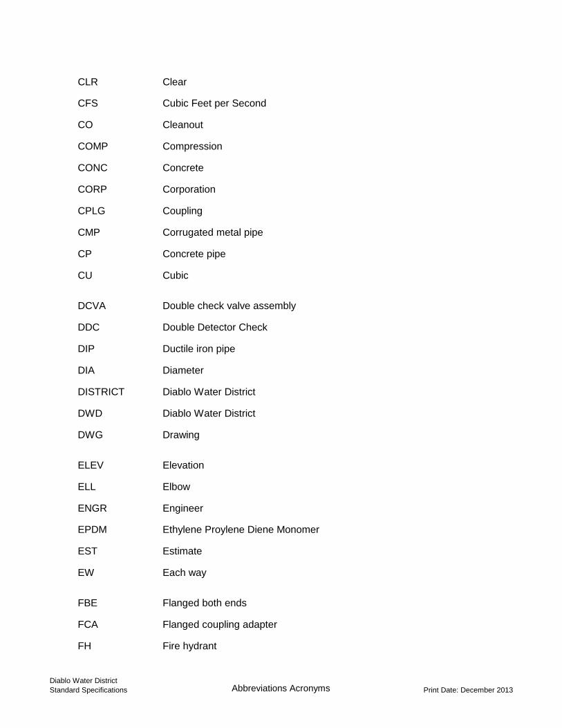
CLR Clear
CFS Cubic Feet per Second
CO Cleanout
COMP Compression
CONC Concrete
CORP Corporation
CPLG Coupling
CMP Corrugated metal pipe
CP Concrete pipe
CU Cubic
DCVA Double check valve assembly
DDC Double Detector Check
DIP Ductile iron pipe
DIA Diameter
DISTRICT Diablo Water District
DWD Diablo Water District
DWG Drawing
ELEV Elevation
ELL Elbow
ENGR Engineer
EPDM Ethylene Proylene Diene Monomer
EST Estimate
EW Each way
FBE Flanged both ends
FCA Flanged coupling adapter
FH Fire hydrant
Diablo Water District
Standard Specifications Abbreviations Acronyms Print Date: December 2013
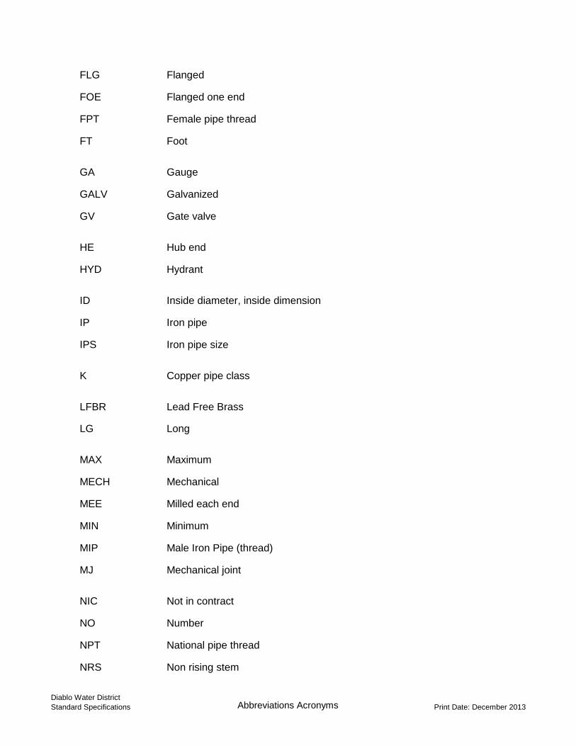
FLG Flanged
FOE Flanged one end
FPT Female pipe thread
FT Foot
GA Gauge
GALV Galvanized
GV Gate valve
HE Hub end
HYD Hydrant
ID Inside diameter, inside dimension
IP Iron pipe
IPS Iron pipe size
K Copper pipe class
LFBR Lead Free Brass
LG Long
MAX Maximum
MECH Mechanical
MEE Milled each end
MIN Minimum
MIP Male Iron Pipe (thread)
MJ Mechanical joint
NIC Not in contract
NO Number
NPT National pipe thread
NRS Non rising stem
Diablo Water District
Standard Specifications Abbreviations Acronyms Print Date: December 2013
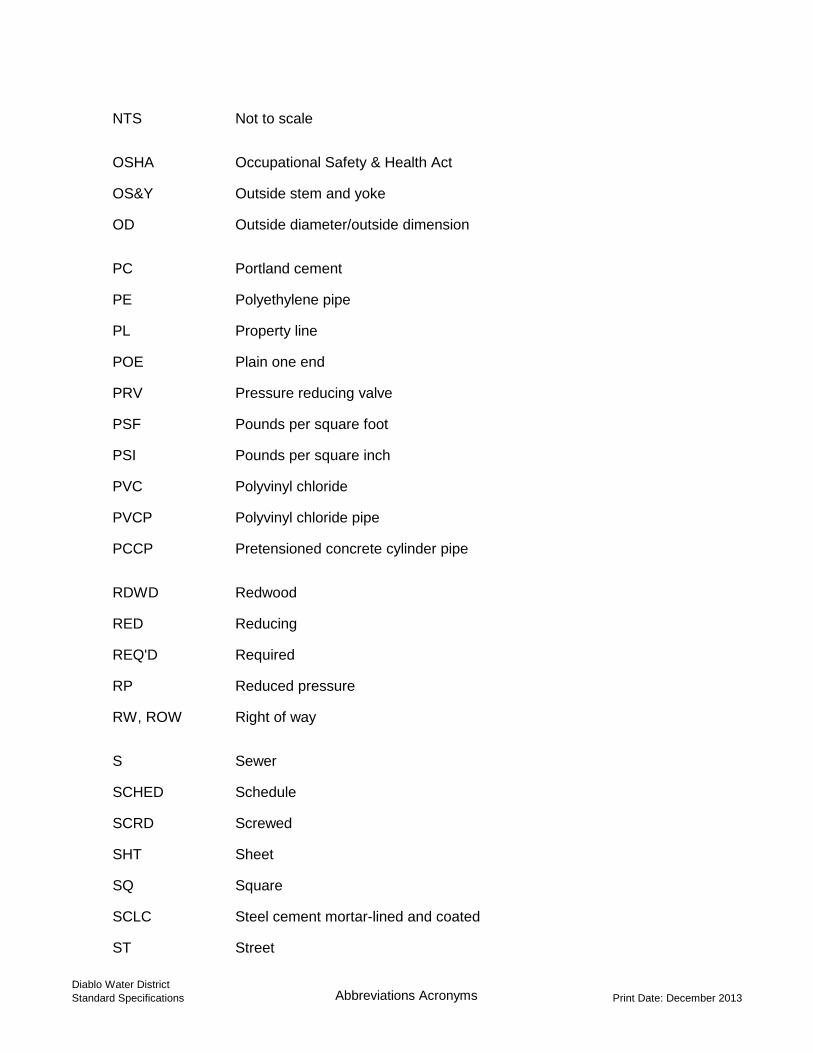
NTS Not to scale
OSHA Occupational Safety & Health Act
OS&Y Outside stem and yoke
OD Outside diameter/outside dimension
PC Portland cement
PE Polyethylene pipe
PL Property line
POE Plain one end
PRV Pressure reducing valve
PSF Pounds per square foot
PSI Pounds per square inch
PVC Polyvinyl chloride
PVCP Polyvinyl chloride pipe
PCCP Pretensioned concrete cylinder pipe
RDWD Redwood
RED Reducing
REQ'D Required
RP Reduced pressure
RW, ROW Right of way
S Sewer
SCHED Schedule
SCRD Screwed
SHT Sheet
SQ Square
SCLC Steel cement mortar-lined and coated
ST Street
Diablo Water District
Standard Specifications Abbreviations Acronyms Print Date: December 2013
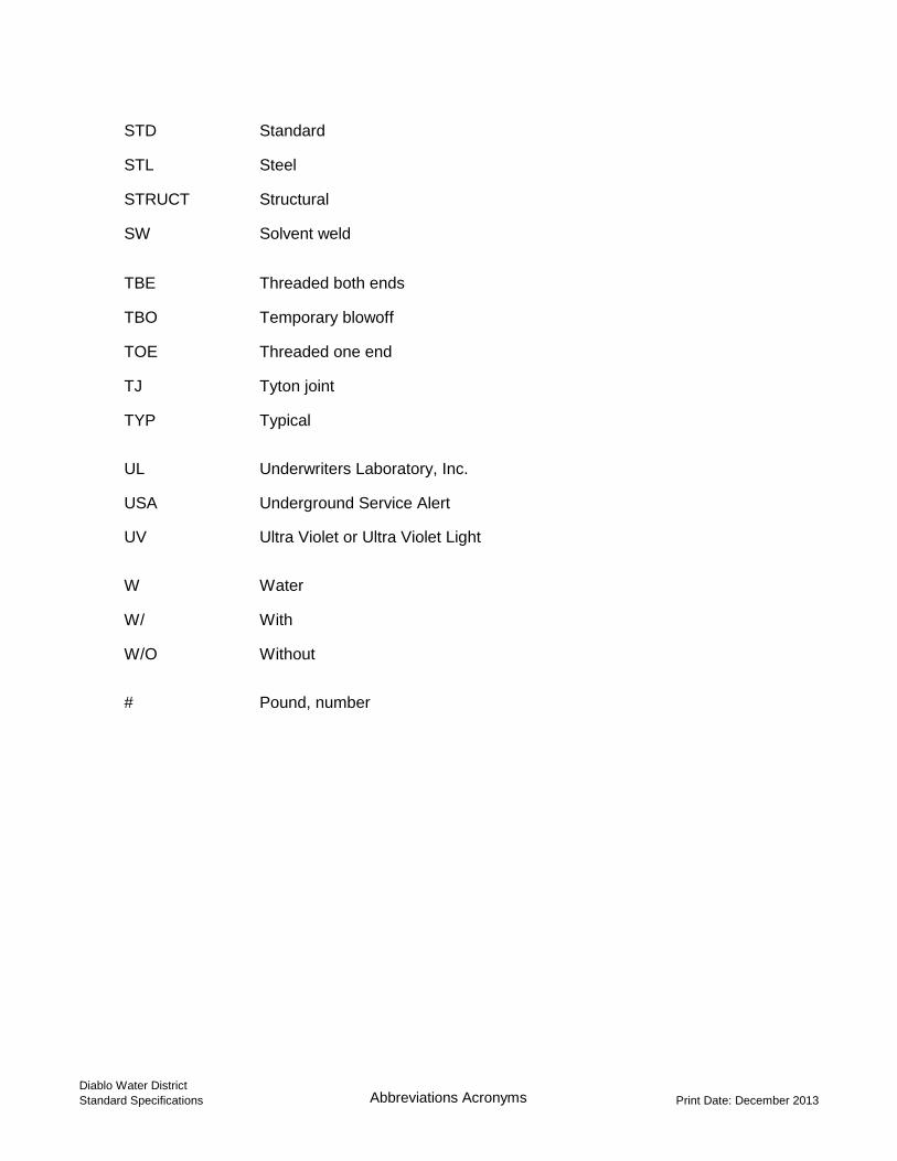
STD Standard
STL Steel
STRUCT Structural
SW Solvent weld
TBE Threaded both ends
TBO Temporary blowoff
TOE Threaded one end
TJ Tyton joint
TYP Typical
UL Underwriters Laboratory, Inc.
USA Underground Service Alert
UV Ultra Violet or Ultra Violet Light
W Water
W/ With
W/O Without
# Pound, number
Diablo Water District
Standard Specifications Abbreviations Acronyms Print Date: December 2013
4. General Requirements
General Requirements - 1 Diablo Water District Print Date: December 2013 Standard Specifications
GENERAL REQUIREMENTS
PART 1 GENERAL 1.01 PURPOSE OF STANDARD SPECIFICATIONS AND DRAWINGS
A. The purpose of these Standard Specifications and Drawings is to provide
certain minimum requirements for the design, materials used, and methods of construction for Diablo Water District's water system facilities whether in public or private property.
1.02 DEFINITIONS
A. As used in these Standard Specifications and Drawings, the following terms have the meanings indicated:
1. "APPLICANT": Any individual, developer, partnership, public
agency, or corporation requesting water service from the District. 2. "BOARD OF DIRECTORS": The Board of Directors of Diablo
Water District. 3. "CONTRACTOR": The person or persons, firm or firms, co-
partnership or corporation, who has or have entered into a contract with an Applicant or the District to perform work on water lines and appurtenances which are to be the property of or under the jurisdiction of the District.
4. "DISTRICT" or “OWNER”: Diablo Water District, acting through its
Board of Directors or authorized representatives. 5. "DRAWINGS" and "SPECIFICATIONS": Drawings and
specifications for water service prepared by an Applicant or his representative.
6. "ENGINEER": As designated by the District, the engineer or
authorized representative representing Diablo Water District. 7. "STANDARD DRAWINGS" and "STANDARD SPECIFICATIONS":
Drawings and written matter included herein together with changes or additions which may be attached hereto.
8. "SUBCONTRACTOR": An individual, firm, or corporation having a
direct contract with Contractor or any other subcontractor for the performance of a part of the Work at the site.
9. "WORK": Any and all obligations, duties, and responsibilities
necessary to the successful completion of the project assigned to
General Requirements - 2 Diablo Water District Print Date: December 2013 Standard Specifications
or undertaken by a contractor under contract to the District, including all labor, materials, equipment, and other incidentals, and the furnishing thereof.
B. In addition, other Standard Specifications and Standard Methods are
incorporated by reference and shall be considered a part of these Specifications as applicable. In general, the Standards in question shall be the latest amended standards adopted by the American Standards Association (ASA), by the American Water Works Association (AWWA), by the American Society of Civil Engineers (ASCE), by the American Society of Mechanical Engineers (ASME), by the American Welding Society (AWS), by the federal government, State of California, and County of Contra Costa. All referenced standards shall be the most recent version or edition.
1.03 PLAN REVIEW AND APPROVAL PROCESS
A. GENERAL: All work necessary to the installation of water mains and appurtenances to provide water service shall be shown on drawings furnished by an Applicant. The drawings shall be prepared under the direction of, and signed by, a currently registered professional engineer in the State of California.
B. DESIGN: Design of the water system improvements and preparation of the
drawings shall following the requirements contained in the “Design Requirements” Section of this document. This work shall include cathodic protection improvements as required for the water facilities.
All calculations requested by the District to verify the design of any portion
of the water system shall be submitted. Calculations shall be based on methods generally accepted by the engineering profession and shall be neatly and legibly done in such form as to enable them to be readily checked. Literature and technical data concerning any of the materials and equipment proposed to be used shall be furnished upon request. If requested, soils report for the project area shall be submitted as part of the review process.
C. APPROVAL OF DRAWINGS: Four sets of prints of the drawings showing
the proposed work shall be submitted to the District for approval. The “Subdivision Water System Design Requirements and Plan Review Checklist” contained herein under “Design Requirements” shall be submitted with the drawings, with the applicable boxes checked by the Design Engineer. If the applicable design requirements are not followed, an explanation shall be provided with the submittal.
The District shall review the drawings and provide comments in writing, as
appropriate. The Applicant shall revise the drawings to address District comments, and re-submit the drawings as many times as needed to obtain District approval. Upon approval of the drawings the District shall so notify
General Requirements - 3 Diablo Water District Print Date: December 2013 Standard Specifications
the Applicant in writing. Applicant shall deliver four sets of final signed plans to the District prior to commencement of construction.
1.04 PRIOR TO COMMENCEMENT OF CONSTRUCTION
A. APPPROVED PLANS: Prior to commencement of construction, all drawings must be approved and fully signed by all approving agencies. Cathodic protection design and plans must be completed and approved, including submittal of soils test results for the cathodic protection design.
B. AGREEMENT: Prior to commencement of construction, the Applicant
shall enter into an agreement with the District. The agreement must be adopted by the District Board of Directors.
If within one year after the date of the approval of the drawings, the Applicant and the District have not executed an agreement for the construction of the work, the approval will then expire and be of no further effect. If thereafter the Applicant determines to execute an agreement with the District, four additional sets of prints shall be submitted to the District for approval. If the Applicant fails to commence and complete the work within the times stipulated in the Agreement, the District may rescind its approval of the drawings and require as a condition of the agreement specific modifications and revisions of the drawings.
C. BONDS AND INSURANCE: Prior to commencement of construction, the
Applicant shall deliver to the District all bonds and insurance certificates as required by the Agreement.
D. CONTRACTOR: District shall approve the Contractor selected by the
Applicant prior to commencement of construction. E. PERMITS: Applicant shall obtain all required permits for installation of the
facilities at his/her own expense. 1.05 CONDUCT OF CONSTRUCTION WORK
A. GENERAL: No work on facilities for, or related to, the District's water system shall be done until all drawings, including cathodic protection, have been approved by the District. Notification that the drawings are found in conformance with District standards shall not relieve the Applicant or Contractor of any responsibilities indicated in the Standard Specifications and Standard Drawings. Contractor shall at all times have at the work site this volume of the District's Standard Specifications and Drawings.
B. SUBMITTALS: No work on facilities for, or related to, the District's water
system shall be done until all necessary literature and technical data, for all materials, equipment and appurtenances proposed to be used, have been submitted to, and approved by, the District. Contractor shall have approved submittals on site at all times.
General Requirements - 4 Diablo Water District Print Date: December 2013 Standard Specifications
1. The Contractor shall not install any equipment or materials until the District has approved all submittals. If any equipment or materials are installed prior to approval of the submittals, it shall be at the Contractor’s risk.
2. In general, corrections or comments or lack thereof, made relative
to submittals during review, shall not relieve the Contractor from compliance with the requirements of the drawings and specifications. Submittals are for review of general conformance with the design concepts of the project and general compliance with the contract documents. The Contractor is responsible for the final design conforming and correlating all quantities and dimensions, selecting fabrication processes and techniques of construction, coordinating the work of all trades, and performing the work in a safe and satisfactory manner.
C. MATERIALS: All materials shall be checked on location by the Contractor.
After materials have been received and checked by the Contractor, the Contractor shall notify the District that the proper materials have been delivered. No work shall commence until the District has inspected the materials.
D. SAFETY OFFICER: The Contractor’s Safety Officer shall be on location at
all times during construction activities. E. INSPECTION: All materials furnished and all work performed shall be
subject to inspection by the District. The materials and work shall be held strictly to the true intent of the Standard Specifications and Drawings in regard to quality of materials, workmanship, and diligent execution. Such inspection may include mill, plant, shop, or field inspection, as required. The District inspector shall be permitted access to all parts of the work, including plants where materials or equipment are manufactured or fabricated, and he shall be furnished with such materials, information, and assistance as is required to make a complete and detailed inspection.
F. WORK DONE IN THE ABSENCE OF INSPECTION: Work done in the
absence of prescribed inspection may be required to be removed and replaced under the proper inspection, and the entire cost of removal and replacement, including the cost of all materials and labor which may be furnished by the District and used in the work thus removed, shall be borne by the Contractor, regardless of whether the work removed is found to be defective or not. Work covered up without the authority of the District, shall, upon order of the District, be uncovered to the extent required, and the Contractor shall similarly bear the entire cost of performing all the work and furnishing all the materials necessary for the removal of the covering and its subsequent replacement, as directed and approved by the District.
G. TESTING: The District may make, or have made, such tests as he deems necessary to ensure that the work is being accomplished in accordance with the requirements of the District. In the event that any tests reveal
General Requirements - 5 Diablo Water District Print Date: December 2013 Standard Specifications
noncompliance with the requirements of the contract, the Contractor shall bear the cost of such corrective measures deemed necessary by the District, as well as the cost of subsequent retesting.
H. DEFECTIVE MATERIAL OR WORK: Materials or work not conforming to
the requirements of these Standard Specifications, Drawings or submittals shall be considered as defective, and all such materials, whether in place or not, shall be rejected. No rejected material, the defects of which have been subsequently corrected, shall be used until approved in writing by the District.
I. DISCREPANCIES IN THE STANDARD SPECIFICATIONS AND
DRAWINGS: Any discrepancies, errors, or omissions, found in these Standard Specifications and Drawings shall be promptly reported to the District who may issue a correction or clarification in writing. The Contractor shall not take advantage of any such discrepancies, errors, or omissions, but shall comply with any corrective measures regarding the same prescribed by the District.
1.06 AT COMPLETION OF CONSTRUCTION - PRIOR TO FINAL ACCEPTANCE
A. TESTING: Testing of all facilities shall be conducted according to all specifications and requirements contained herein. No facilities shall be accepted until the results of all final tests are satisfactory to the District.
B. PUNCH LIST: All work and punch list items must be completed. The
District shall assess a time frame for all punch list items to be completed. If not completed by the designated time, the District shall do so or have done by others after contacting the bonding company. The District will increase the deposit to cover the estimated punch list items. The deposit shall be refunded if the punch list is completed to the District’s satisfaction within the stated timeframe.
C. RECORD DRAWINGS: One full-size reproducible set of prints, revised to
show record conditions shall be furnished to the District along with two sets of prints made from this record reproducible set. The reproducible set shall be photo quality on vellum or plain mylar; sepia or diazo mylar is not acceptable. It is suggested that a blue-line set of record drawings be provided for District review prior to submitting the mylars. GPS coordinates shall be surveyed and recorded for all aboveground and underground valves, meters, fittings, and blowoffs (including elevations for all underground facilities). GPS coordinates shall also be collected from other utilities exposed during construction of new utilities.
D. CATHODIC PROTECTION (if required): Shall be tested and certified by
registered engineer. Record drawings (mylars) shall be submitted. It is suggested that a blue-line set of record drawings be provided for District review prior to submitting the mylars. GPS coordinates shall be surveyed and recorded for all at-grade cathodic protection test stations.
General Requirements - 6 Diablo Water District Print Date: December 2013 Standard Specifications
1.07 FINAL ACCEPTANCE
A. ACCEPTANCE: Acceptance of an Applicant's project shall be made in writing by the District's General Manager after the work has been completed in accordance with District standards and approved drawings, and has been inspected and tested.
PART 2 CONSTRUCTION MATERIALS 2.01 SCOPE OF WORK
A. All materials delivered to the worksite, necessary to complete all work as shown on the drawings and/or as herein specified, including, but not limited to: pipe, fittings, valves, hydrants, and concrete.
2.02 MATERIAL SPECIFICATIONS
A. The Technical Specifications described herein contain the specific requirements for various materials.
B. All materials shall be new; shall bear the manufacturer's stamp or marking;
and shall conform to the most current revision of the cited specification(s).
C. The Contractor shall, at any time when requested, submit to the District, proper authenticated documents or other satisfactory proofs of compliance with the requirements of these specifications.
2.03 DELIVERY, STORAGE AND HANDLING
A. During loading, transportation and unloading, care shall be taken to
prevent damage to pipes and coating. Carefully load and unload each pipe under control at all times. Place skids or blocks under each pipe in the shop and securely wedge pipe during transportation to ensure no injury to pipe and lining. Pipe ends shall be covered during transport to prevent contaminants from entering the pipe.
B. Any pipe damaged in shipment shall be replaced as directed by the
District. C. While stored, pipe shall be adequately supported from below at not more
than 3 feet intervals to prevent deformation. Pipe shall not be stacked higher than 6 feet. Pipe and fittings shall be stored in a manner which will keep them at ambient outdoor temperatures. Temporary shading as required to meet this requirement shall be provided. Simple covering of the pipe and fittings which allows temperature buildup when exposed to direct sunlight will not be permitted.
D. The pipe shall be handled by use of wide slings, padded cradles, or other
devices, acceptable to the District, designed and constructed to prevent
General Requirements - 7 Diablo Water District Print Date: December 2013 Standard Specifications
damage to the pipe coating. The use of chains, hooks, or other equipment which might injure the pipe coating will not be allowed. Stockpiled pipe shall be suitably supported and shall be secured to prevent accidental rolling. Pipe ends shall be protected from the weather. All other pipe handling equipment and methods shall be acceptable to the District.
E. Stockpiled pipe shall be supported on sand or earth berms free of rock
exceeding 3 inches in diameter. The pipe shall not be rolled and shall be secured to prevent accidental rolling.
F. The Contractor shall be fully liable for the replacement or repair of pipe
which is damaged or has been rejected by the District. PART 3 GENERAL CONSTRUCTION REQUIREMENTS 3.01 RIGHT-OF-WAY
A. Water mains, services, and meters shall be located in public right-of-way. In special cases, subject to the approval of the District, water mains may be located in a minimum twenty (20) foot wide utility easement dedicated to the District. Water mains shall be located five (5) feet from either edge of an easement. Additional utility easements may be required to accommodate water meters and other water facilities.
3.02 LOCATION OF EXISTING DISTRICT FACILITIES A. Contractor agrees to take all responsibility for locating existing District
facilities which may be within 10 feet of the Work. Contractor shall be responsible for ensuring that the Underground Service Alert (1-800-227-2600) has been contacted before commencement of the Work and that the District’s facilities have been adequately marked. Contractor shall dig by hand and by the use of probes to locate all existing District facilities prior to the use of mechanical equipment.
3.03 COMPLIANCE WITH STATE DEPARTMENT OF HEALTH SERVICES
A. All requirements of the State Department of Health Services including, but
not limited to, water main-sanitary sewer separation distances, and pipe material specifications, shall be complied with.
3.04 INDIVIDUAL PRESSURE REDUCING VALVES ON CUSTOMER SERVICES
A. As described in the “Design Requirements” Section of this document,
individual pressure reducing valves shall be required on all customer services at locations designated by the District with ground elevations less than 15 feet above mean sea level.
3.05 LINE AND GRADE A. The Contractor shall lay out the work in advance of beginning construction.
General Requirements - 8 Diablo Water District Print Date: December 2013 Standard Specifications
The Contractor is responsible for constructing the work to the lines and grades shown in the Contract Documents. The trench shall be excavated to a flat bottom, cut true and even to the established grade. Construction staking in new developments will be provided by the Applicant.
3.06 INSTALLATION OF WATER MAINS
A. All pipe, fittings, and specials, shall be carefully handled and protected against damage to lining and coating, impact shocks and free fall. Pipe shall not be placed directly on rough ground but shall be supported in a manner which will protect the pipe against injury whenever stored at the site of the work or elsewhere. No pipe shall be installed when the lining or coating show cracks as defined in AWWA C205. Such damaged lining and coating shall be repaired, or a new undamaged pipe or fitting shall be furnished and installed. In the event a new and undamaged pipe is furnished, the damaged pipe shall be marked by the District and removed from the site.
B. Before placement of pipe in the trench, each pipe or fitting shall be
thoroughly cleaned of any foreign substance which may have collected thereon and shall be kept clean at all times thereafter. For this purpose, the openings of all pipes and fittings in the trench shall be closed during any interruption in the installation of the pipe. All pipe, fittings, valves, etc., shall be carefully lowered into the trench by suitable tools or equipment, in such manner as to prevent damage to the pipe, lining, coating, fitting or other appurtenances. Damage to the lining or coating shall be repaired to the satisfaction of the Engineer before the pipe or fitting is installed.
C. The Contractor shall inspect each pipe and fitting to ensure there are no
damaged portions of the pipe. The Contractor shall remove or smooth out any burrs, gouges, weld splatter or other small defects prior to laying pipe.
D. The District may examine each bell and spigot end to determine whether
any preformed joint has been damaged prior to installation. Any pipe having defective joint surfaces shall be rejected, marked as such, and immediately removed from the job site.
E. Pipe shall be laid to the lines and grades shown on the Drawings with
bedding and backfill as shown on the Drawings. Blocking under the pipe will not be permitted. The deflection at joints shall not exceed that recommended by the manufacturer. If any defective pipe is discovered after it has been installed, it shall be removed and replaced with a sound pipe in a satisfactory manner by the Contractor, at his own expense.
F. The materials used for the bedding, and the amount thereof, and the
manner of deposition shall be subject to the approval of the District, but the Contractor shall be held responsible for any displacement or instability of pipelines or any damage to coatings caused by improper installation of bedding materials.
General Requirements - 9 Diablo Water District Print Date: December 2013 Standard Specifications
G. Installation of pipes in prepared trenches shall start at the lowest elevation, with the spigot ends pointing in the direction of flow. Pipe shall be protected from lateral displacement by placing the specified pipe embedment material. Pipe shall be laid with the bell ends facing the direction of laying except when reverse laying is specifically authorized by the District.
H. The pipe shall be laid true to line, with no visible change in alignment at
any joint, unless curved alignment is shown on the drawings. No single piece of pipe shall be laid unless it is generally straight. The centerline of the pipe shall not deviate from a straight line drawn between the centers of the openings at the ends of the pipe by more than 1/16 inch per foot of length. If a piece of pipe fails to meet this requirement check for straightness, it shall be rejected and removed from the site.
I. Except for short runs which may be permitted by the District, pipes shall be
laid uphill. Pipe which is laid on a downhill grade shall be blocked and held in place until sufficient support is furnished by the following pipe to prevent movement. Pipes shall be laid uphill on grades exceeding 10 percent.
J. Good alignment shall be preserved during installation. Fittings, in
addition to those shown on the plans, shall be provided, if required, in crossing utilities which may be encountered upon opening the trench.
K. Pipe joints shall be made only with the couplings and rubber rings
furnished with the pipe or with mechanical couplings, and aligned and constructed in the trench in accordance with the manufacturer’s instructions.
L. Whenever pipe laying is discontinued for short periods, or when work is
stopped at the end of the day, the open ends of all pipes shall be closed with watertight plugs, bulkheads or other approved means. The plug or bulkhead shall not be removed, unless or until the trench is dry.
M. Under no circumstances shall pipe be laid in water, and no pipe shall be
laid under unsuitable weather or trench conditions. All necessary precautions shall be taken to prevent uplift or flotation of the pipe prior to the completion of the backfilling operation. The Contractor shall assume full responsibility for any damage due to this cause and shall, at its own expense, restore and replace the pipe to its specified condition and grade if it is displaced due to floating.
N. As pipe laying progresses, the Contractor shall keep the pipe interior free of all debris and clean until testing. The Contractor shall completely clean the interior of the pipe of all sand, dirt, mortar splatter and any other debris or foreign matter following completion of pipe laying, pointing of joints and any necessary interior repairs prior to testing and disinfecting the completed pipeline. The lowest segment shall be flushed last to assure debris removal. If, after this cleaning, obstructions remain, they shall be removed.
General Requirements - 10 Diablo Water District Print Date: December 2013 Standard Specifications
O. If any defective item is discovered after it has been installed, it shall be removed and replaced with an exact replacement item in a satisfactory manner by the Contractor, at the Contractor’s own expense.
P. Plastic warning tape shall be installed over all water lines as shown on
Standard Drawing DWD-1. Warning tape shall be blue, minimum 2 inches wide, and printed continuously with the words: “CAUTION BURIED WATER LINE BELOW”.
3.07 WARRANTY A. The manufacturer shall guarantee that the pipe furnished is suitable for the
purpose intended and free from defects of material and workmanship for a period of three years after initial startup. In the event the pipe fails to perform as specified, the pipe manufacturer shall promptly replace defective pipe at no additional cost to the District.
3.08 INTERRUPTION OF SERVICE
A. If the District agrees that a portion of the distribution system needs to be shutdown with interruption of service to hydrants or customers, then a written request, including the shutdown duration and a work plan, shall be submitted to the District for approval. Shutdowns will be limited to the period between 9:00 a.m. and 4:00 p.m., Tuesday through Thursday and preferably should not include mealtime hours. If a shutdown is approved, the District shall be notified 48 hours prior to commencing the work.
B. Preparations shall be made and work planned so that the shutdown time
will be as short as possible. Requests for shutdowns beyond the aforementioned times and days may be reviewed for approval by the District on a case-by-case basis. Should the approved shutdown time be exceeded, a penalty of $100 for every hour over that approved shutdown may be assessed against the party requesting the shutdown.
C. After having secured the approval of the District, the party requesting the
shutdown will notify the local fire protection district and all customers to be affected at least 24 hours in advance of any interruption of service. The fire protection district shall be immediately notified when service to the affected area is restored.
3.09 VALVE OPERATION
A. Only District representatives and individuals specifically designated by the District shall open or close any valve in the existing water system.
3.10 CONNECTING TO EXISTING MAINS A. EXPOSING EXISTING FACILITIES: When connections are to be made to
any existing pipe or other appurtenances, the actual size, elevation, or position or location of which cannot be determined without excavation, the
General Requirements - 11 Diablo Water District Print Date: December 2013 Standard Specifications
Contractor shall carefully excavate and expose the existing facility. The facilities shall be inspected before any connections are made.
B. WET TAPPING: Connections to the water distribution system shall be
made by use of the wet tapping method unless 1) the pipe to be connected is at least 4 inches larger than the main, or 2) the district agrees that wet tapping is impossible or impracticable. Twenty-four hours notice in writing shall be given to the District prior to commencing on any wet tap into the water system.
The work crew performing the wet tap must be acceptable to the District and be capable, experienced, and responsible. The Contractor shall immediately replace any wet tap work crew which the District judges to be irresponsible or unskillful. A representative of the District shall be present before and during any wet taps.
3.11 ABANDONED FACILITIES
A. Buried pipelines and valving to be abandoned shall be abandoned in place unless otherwise indicated "TO BE REMOVED". The ends of such pipelines shall be capped or plugged and all valving shall be closed, if possible. Details with the location, size, and material of the abandoned facility shall be accurately noted on the project record drawings (as-builts).
3.12 CONSTRUCTION WATER SUPPLY
A. All water is to be metered and paid for by the Contractor. Meters for this purpose are available at the District office following application for same, and a deposit is required.
B. The deposit, service charge, and consumption charge will be those stated in the rules and regulations of the District as they are in effect from time to time. The District shall be entitled to assess such charges against the Contractor and deduct the cost thereof from any money due or that may become due the Contractor under this or any other contract.
3.13 FILLING WATER TRUCKS AND OTHER WATER TRANSPORT EQUIPMENT
FROM FIRE HYDRANTS
A. An air gap or an approved reduced pressure principle backflow preventer shall be utilized to isolate the water system from the water storage compartment being filled. See the figure on the following page.
3.14 SAFETY
A. The Contractor’s Safety Officer shall be on location at all times. B. The Contractor shall at all times conduct his work in accordance with
Construction Safety Orders of the Division of Industrial Safety, State of California, to ensure the least possible obstruction to traffic and
General Requirements - 12 Diablo Water District Print Date: December 2013 Standard Specifications
inconvenience to the general public, and adequate protection of persons and property in the vicinity of the work. No street shall be closed to the public without first obtaining permission of the District and the other proper governmental authorities.
C. Toe boards shall be provided to retain excavated materials if required by
the District or the public entity having jurisdiction over the street or highway. Fire hydrants on or adjacent to the work shall be kept accessible to fire fighting equipment at all times. Temporary provisions shall be made by the Contractor to ensure the use of sidewalks and the proper functioning of all gutters, sewer inlets, and other drainage facilities.
3.15 MAINTENANCE OF TRAFFIC
A. Contractor shall conduct his work to interfere as little as possible with public travel, whether vehicular or pedestrian. Whenever it is necessary to cross, obstruct, or close roads, driveways, and walks, whether public or private, Contractor shall provide and maintain suitable and safe bridges, detours, or other temporary expedients for the accommodation of public and private travel, and shall give reasonable notice to owners of private drives before interfering with them. Such maintenance of traffic will not be required when Contractor has obtained permission from the owner and tenant of private property, or from the authority having jurisdiction over public property involved, to obstruct traffic at the designated point. Traffic control shall be provided by applicant or contractor as needed for District personnel to operate valves or other activities. It is the Contractor’s responsibility to contact local governing agencies regarding submittal and approval of traffic detour plans prior to the commencement of work.
3.16 BARRICADES AND LIGHTS A. All streets, roads, highways, and other public thoroughfares which are
closed to traffic shall be protected by effective barricades on which shall be placed acceptable warning signs. Barricades shall be located at the nearest intersecting public highway or street on each side of the blocked section.
B. All open trenches and other excavations shall have suitable barricades,
signs, and lights to provide adequate protection to the public. Obstructions such as material piles and equipment shall be provided with similar warning signs and lights.
C. All barricades and obstructions shall be illuminated with warning lights
from sunset to sunrise. Material storage and conduct of the Work on or alongside public streets and highways shall cause the minimum obstruction and inconvenience to the traveling public.
D. All barricades, signs, lights, and other protective devices shall be installed
and maintained in conformity with applicable statutory requirements.
General Requirements - 13 Diablo Water District Print Date: December 2013 Standard Specifications
3.17 SANITARY FACILITIES
A. Contractor shall furnish temporary sanitary facilities at the site for the needs of all construction workers and others performing work or furnishing services on the project. Sanitary facilities shall be of reasonable capacity, properly maintained throughout the construction period, and obscured from public view to the greatest practical extent. Contractor shall enforce the use of such sanitary facilities by all personnel at the site.
3.18 CARE OF EXISTING STRUCTURES AND UTILITIES
A. GENERAL: Existing power and telephone lines, trees, fences, water pipes, gas lines, sewer or other conduits, embankments, and sundry structures, in the vicinity of the work shall be supported and protected from injury by the Contractor during the construction and until the completion of the work. The Contractor shall be liable for all damages done to such structures.
B. EXISTING UTILITIES: Contractor shall be responsible for ensuring that
the Underground Service Alert (1-800-227-2600) has been contacted before commencement of the Work and that all existing utilities in the vicinity of the work have been marked.
C. RELOCATION OF EXISTING UTILITIES: The Contractor shall make all
arrangements for, and pay all costs connected with, any necessary relocation and/or reconstruction of existing surface and underground utility facilities (including without limitation, poles, guys, conduits, pipes, and mains) affecting the project or the work to be performed.
D. UNIDENTIFIED EXISTING UTILITIES: If, in the performance of the work,
an existing utility is encountered which is not shown on the drawings and is not apparent or inferable from visual inspection of the site, the District shall be notified immediately. The District will determine whether the drawings or specifications shall be modified, or whether the existing utility shall be relocated or whether the Contractor shall work around the existing utility.
E. PROTECTION OF TREES, SHRUBS AND LAWNS: The Contractor shall
take every necessary precaution to protect trees, shrubs, lawns, and other vegetation in all areas on or adjacent to the worksite(s). No trees or shrubs shall be removed or trimmed unless the drawings specifically state otherwise.
3.19 MAINTAINING DRAINAGE
A. The Contractor shall provide and maintain temporary drainage for all excavations, drains, sewers, ditches, trenches, and structures. The Contractor shall keep the excavations dry throughout the construction operations. Whenever necessary in order to provide proper drainage, the Contractor shall, at his own expense, install underdrains, and furnish and operate all necessary pumping equipment, drainage sumps, wellpoint
General Requirements - 14 Diablo Water District Print Date: December 2013 Standard Specifications
systems, and other drainage facilities. The laying of pipe or placing of concrete will not be allowed under circumstances where water is standing in the excavation.
B. The Contractor shall dispose of the water from the work in a suitable manner without damage to adjacent property and in such a manner as not to be a menace to the public health. No water shall be drained into work built or under construction without prior consent of the Engineer.
3.20 RAILROAD CROSSINGS
A. Wherever the work to be done under these specifications includes encroachment upon railroad rights-of-way, easement, or permit, the Applicant and contractor are responsible for entering into an agreement with the railroad company. The Contractor shall comply with all requirements imposed by the railroad company in connection with performance of the work and shall give such notice as is required before beginning work. The Contractor shall be responsible for the payment of any necessary watchmen, flagmen, or inspectors or any other protection required on the work by the railroad.
3.21 DUST CONTROL
A. The Contractor shall at all times keep the streets sufficiently watered and swept of all loose material produced by his operations in order that traffic and construction does not raise an objectionable amount of dust. When directed by the District, the contractor shall apply a suitable dust palliative to control dust.
3.22 NOISE CONTROL
A. The Contractor shall take reasonable measures to avoid unnecessary noise. Such measures shall be appropriate for the normal ambient sound levels in the area during working hours. All construction machinery and vehicles shall be equipped with practical sound muffling devices, and operated in a manner to cause the least noise consistent with efficient performance of the work.
3.23 POLLUTION CONTROL
A. The Contractor shall prevent the pollution of drains and watercourses by sanitary wastes, sediment, debris, and other substances resulting from construction activities. No sanitary wastes will be permitted to enter any drain or watercourse other than sanitary sewers. No sediment, debris, or other substance will be permitted to enter sanitary sewers and reasonable measures will be taken to prevent such materials from entering any drain or watercourse. Applicant and contractor shall be responsible for obtaining any required permits for discharge to the sanitary sewer, and/or for the General Stormwater Permit for Construction Activities, including submittal of the Notice of Intent and preparation of the Stormwater Pollution
General Requirements - 15 Diablo Water District Print Date: December 2013 Standard Specifications
Prevention Plan (SWPPP). 3.24 COUNTY, CITY OR STATE ROADS
A. Whenever the work to be done under these specifications includes encroachment upon county, city, or state road rights-of-way, the Contractor shall comply with all requirements imposed by the governing agency in addition to those set forth in these specifications, in connection with performance of the work and shall give such notice as is required before beginning work.
B. The Contractor is responsible for securing the necessary rights-of-way,
easement, or permit whenever work is to be done under these specifications including encroachment upon county, city, or state road rights-of-way and bear all fees associated herewith.
3.25 SECURITY
A. The Contractor shall be responsible for protection of the site, and all work, materials, equipment, and existing facilities thereon, against vandals and other unauthorized persons.
END OF SECTION
5. Technical Specifications
DIABLO WATER DISTRICT STANDARD SPECIFICATIONS AND DRAWINGS
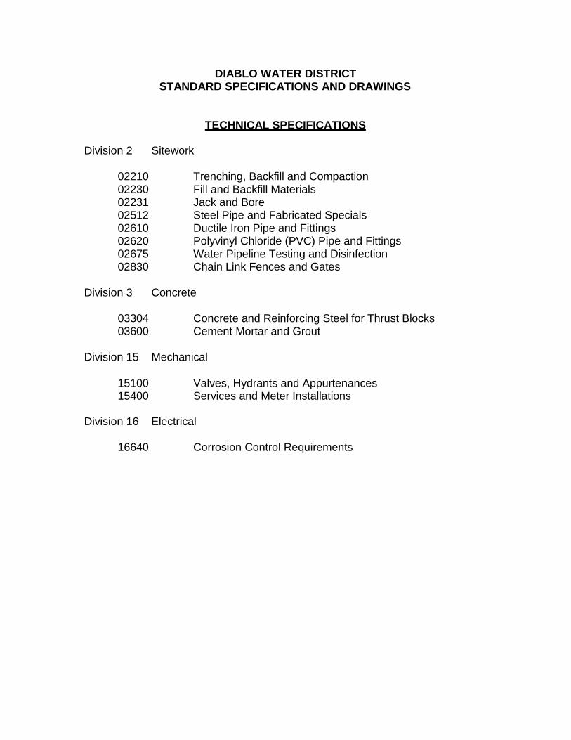
TECHNICAL SPECIFICATIONS
Division 2 Sitework
02210 Trenching, Backfill and Compaction 02230 Fill and Backfill Materials 02231 Jack and Bore 02512 Steel Pipe and Fabricated Specials 02610 Ductile Iron Pipe and Fittings 02620 Polyvinyl Chloride (PVC) Pipe and Fittings 02675 Water Pipeline Testing and Disinfection 02830 Chain Link Fences and Gates
Division 3 Concrete
03304 Concrete and Reinforcing Steel for Thrust Blocks 03600 Cement Mortar and Grout
Division 15 Mechanical
15100 Valves, Hydrants and Appurtenances 15400 Services and Meter Installations
Division 16 Electrical
16640 Corrosion Control Requirements
02210-1 Diablo Water District Print Date: December 2013 Standard Specifications
SECTION 02210
TRENCHING, BACKFILL AND COMPACTION PART 1 GENERAL
1.01 SUMMARY
A. Furnish all labor, materials, equipment and incidentals required and perform all trenching for pipelines and appurtenances, including drainage, filling, backfilling, disposal of surplus material and restoration of trench surfaces and easements.
B. Excavation shall extend to the width and depth shown on the Drawings or as specified herein and shall provide suitable room for installing pipe, structures and appurtenances.
C. Furnish and place all sheeting, bracing and supports and remove from the excavation all materials which the District may deem unsuitable for backfilling. The bottom of the excavation shall be firm, dry and acceptable to the District. No more than 500 feet of open trench will be allowed at any time.
D. The length of open trench shall be related closely to the rate of pipe laying. No more than 500-feet of open trench will be allowed at any time. All pipe shall be backfilled by the end of the day.
E. All excavation, trenching and related sheeting, bracing, etc., shall comply with the requirements of OSHA excavation safety standards (29 CFR Part 1926.650 Subpart P) and State requirements. Where conflict between OSHA and State regulations exists, the more stringent requirements shall apply.
F. Wherever the requirement for "90 percent" or "95 percent" compaction is specified it shall mean at least 90 percent or 95 percent of maximum density as determined by ASTM D1557 (Modified Proctor), Methods A/B/C.
G. Prior to the start of work submit the proposed method of backfilling and compaction to the District for review and approval.
1.02 REFERENCE STANDARDS
A. Referenced standards shall be the most recent version or edition.
B. American Society for Testing and Materials
1. ASTM D1557 – Standard Test Method for Laboratory Compaction Characteristics of Soil Modified Effort
C. American Association of State Highway and Transportation Officials
1. Test No. T180
02210-2 Diablo Water District Print Date: December 2013 Standard Specifications
D. California Department of Transportation
1. Standard Specifications Section 26 – Aggregate Bases
PART 2 PRODUCTS (NOT USED)
PART 3 EXECUTION
3.01 TRENCH EXCAVATION
A. Trench excavation shall include material of every description and of whatever substance encountered, except rock and boulders.
B. Pavement to be removed shall be removed in the manner prescribed by the local city, county, or state governing agency. In addition to the pavement removed for trenches, an additional 12 inches on each side of the trench shall be removed. The pavement shall be saw cut to neat lines prior to trenching, parallel to the trench at the width required. Any pavement damaged outside these lines shall be restored by the Contractor at his/her own expense.
C. Strip and stockpile topsoil from grassed areas crossed by trenches. At the Contractor's option, topsoil may be disposed of and replaced, when required, with approved topsoil of equal quality.
D. While excavating and backfilling is in progress, traffic shall be maintained, and all utilities and other property protected as provided in the General Conditions.
E. Width of Trenches: For pipelines 24 inches and smaller, the width of unsheathed trenches shall not be greater than 24 inches plus the exterior diameter of the pipe barrel. For pipelines larger than 24 inches, unsheathed trenches shall not be greater than 48 inches plus the exterior diameter of the pipe barrel. Where sheathing is required, the width of trench shall be increased only sufficiently to accommodate the sheathing and timbers plus necessary tools and installation equipment. Whenever the maximum allowable trench width is exceeded for any reason, the Contractor shall, at his expense, embed or cradle the pipe in concrete in a manner satisfactory to the District. In no case shall the free working space on each side of the pipe be less than 9 inches.
F. Maximum Length of Open Trench: Unless otherwise specified or directed by the District, the maximum length of open trench shall be 500 feet, or the distance necessary to accommodate the amount of pipe installed in a single day, whichever is greater. The distance is the collective length of any location, including open excavation, pipe laying and appurtenant construction and backfill which has not been temporarily resurfaced. Failure by the Contractor to comply with the limitations specified herein may result in an order to halt progress of the work until compliance has been achieved.
G. Trenches shall be excavated to the depth indicated on the Drawings and in specified widths sufficient for laying the pipe, bracing and for pumping and drainage facilities. The bottom of the excavations shall be firm and dry and
02210-3 Diablo Water District Print Date: December 2013 Standard Specifications
acceptable to the District. When trench excavations exceed the regulated depth, the Contractor shall apply for a “Permit to perform excavation or trench work” from the nearest office of the Division of Occupational Safety and Health.
H. Where the bottom of the trench is found to be unstable or to include material which, in the opinion of the District, is unsuitable for proper bedding of pipelines, the Contractor shall over excavate and remove such material to the width and depth ordered by the District. Before the pipe is laid, a new subgrade shall be prepared by backfilling and compacting with an approved material in layers of not more than 6 inches in uncompacted depth. The layers shall be thoroughly compacted as required to provide adequate bearing and support.
I. Where the bottom of the trench is found to consist of material which is unstable to a degree that, in the opinion of the District, it cannot be removed and replaced with an approved material to properly support the pipeline, the Contractor shall construct a foundation for the pipe in accordance with plans prepared by the District.
J. Excavation and dewatering shall be accomplished by specified methods which preserve the undisturbed state of subgrade soils. The trench may be excavated by machinery to, or just below the designated subgrade, provided that material remaining in the bottom of the trench is no more than slightly disturbed. Subgrade soils which become soft, loose, "quick", or otherwise unsatisfactory as a result of inadequate excavation, dewatering or other construction methods shall be removed and replaced by aggregate base or crushed rock as required by the District at the Contractor's expense.
K. Clay and organic silt soils are particularly susceptible to disturbance due to construction operations. When excavation is to end in such soils, use a smooth-edge bucket to excavate the last 1 foot of depth.
L. Trench excavation shall include the removal of all soil, rock, pavement, tree stumps (or other vegetation or vegetable matter), waste or debris, abandoned pipelines or other structures, ground water and materials of any nature which interfere with the construction work.
M. Where pipe is to be laid directly on the trench bottom, final excavation at the bottom of the trench shall be performed manually, providing a flat bottom true to grade upon undisturbed material. Bell holes shall be made as required.
N. Additional manual excavation may be required if a suitable foundation cannot be achieved with mechanical equipment. Bell holes shall be made as required.
O. At the end of each day all open trenches within paved streets shall be backfilled or steel plated with decking and adequate trench bracing to facilitate the next day's work unless otherwise required by governmental permit. The use of steel plating and decking above the open trench must be approved by the District for each location, and shall be limited to exposure of the pipe end of the last length of pipe installed. No other open trenches shall be allowed at the end of each workday, except by written permission of the District. Alternative protective
02210-4 Diablo Water District Print Date: December 2013 Standard Specifications
measures may only be utilized following receipt of written permission by the District.
3.02 OVEREXCAVATION
A. Wherever, due to over excavation or inaccurate trimming, the Contractor shall refill and compact the trench with backfill material, specified herein, and consolidate and reshape the trench bottom to the required cross-section and grade.
3.03 DISPOSAL OF MATERIALS
A. Excavated materials shall be stored so as to offer minimum obstruction to traffic and the normal use of adjacent properties. Excavated material shall be stacked without excessive surcharge to the trench bank and without obstructing free access to hydrants, valves, meters, or private drives. Inconvenience to traffic and abutters shall be avoided as much as possible. Excavated material shall be segregated for use in backfilling as specified below.
B. The Contractor shall make the necessary arrangements for, and shall remove and dispose of all excess excavated material. The Contractor shall not dump material on any private property without the permission of the property owner thereof.
C. It is the intent of these Specifications that all surplus material from the combined phases of the project not required for backfill or fill shall be disposed of by the Contractor outside the limits of the public rights-of-way and/or easements.
D. No excavated material shall be deposited on private property unless written permission from the property owner thereof is secured by the Contractor.
E. Should conditions make it impracticable or unsafe to stack material adjacent to the trench, the material shall be hauled and stored offsite.
3.04 SHEETING AND BRACING
A. Where necessary, trenches and other excavations shall be properly sheathed and braced to furnish acceptable working conditions. Bracing shall comply in all respects to rules, orders and regulations prescribed by the California Administrative code, Title 8, Chapter 4.
B. Furnish, put in place, and maintain sheeting and bracing required by Federal, State or local safety requirements to support the sides of the excavation and prevent loss of ground which could endanger personnel, or structures or delay the work. If in the District’s opinion proper supports have not been provided, he/she may order additional supports placed at the expense of the Contractor. Compliance with such order shall not relieve the Contractor from his/her responsibility for the sufficiency of such supports. Care shall be taken to prevent voids outside of the sheeting, but if voids are formed, they shall be immediately filled and compacted.
02210-5 Diablo Water District Print Date: December 2013 Standard Specifications
C. Shoring of any nature will be in accordance with OSHA standards or more stringent if needed. The Contractor shall ensure all safety requirements are met.
D. The bracing shall be arranged not to place stress on portions of the completed work until the construction thereof has proceeded far enough to provide ample strength. Any damage to structures occurring through settlement, water or earth pressures, slides, caves, or other causes, due to failure or lack of sheeting or bracing, or improper bracing, or through negligence or fault of the Contractor in any manner, shall be repaired by the Contractor. Sheet piling and other timbering shall be withdrawn in such a manner as to prevent caving of the walls of excavations or damage to piping or other structures.
E. When moveable trench bracing such as trench boxes, moveable sheeting, shoring or plates are used to support the sides of the trench, care shall be taken in placing and moving the boxes or supporting bracing to prevent movement of the pipe, or disturbance of the pipe bedding and the screened gravel or crushed rock backfill.
1. When installing flexible pipe, trench boxes, moveable sheeting, shoring or plates shall not be allowed to extend below the springline of the pipe. As trench boxes, moveable sheeting, shoring or plates are moved, screened gravel or crushed rock shall be placed to fill any voids created and the screened gravel and backfill shall be recompacted to provide uniform side support for the pipe.
F. Steel sheeting may be used in lieu of wood sheeting for the entire job wherever the use of sheeting is necessary.
G. All sheeting and bracing shall be carefully removed in such manner as not to endanger the construction of other structures, utilities, or property, whether public or private. All voids left after withdrawal of sheeting shall be immediately refilled with sand by compacting with tools especially adapted to that purpose, by watering or as directed by the District.
H. When trench excavations exceed the regulated depth, the Contractor shall apply for a “permit to perform excavation or trench work” from the nearest office of the Division of Occupational Safety and Health.
3.05 TRENCH BACKFILL REQUIREMENTS – GENERAL
A. Under normal conditions, minimum cover for water mains in major streets shall be 4 feet from the top of the pipe to the finished ground surface. Water mains within subdivisions shall have a minimum of 3 feet of cover. PVC and ductile iron may be laid to a maximum cover of 5 feet to clear obstructions. Where greater depths are required to clear obstructions, steel offsets as shown on Standard Drawings DWD 6 and DWD 7 shall be used. When minimum cover requirements cannot be met, a concrete reinforced pipeline cover section per DWD 4 shall be used, with the District’s permission.
02210-6 Diablo Water District Print Date: December 2013 Standard Specifications
B. Before backfilling, the trench shall be cleared of all timber and debris such as wood blocks, grade stacks, paper, rope, rags, loose rock over 3 inches, and broken pavement. Care shall be taken to ensure that backfill material is free of debris.
C. During the process of backfilling, any timbering, sheeting, shoring, and sheet piling used to shore the excavation shall be carefully removed by the Contractor in such a manner as will result in a minimum of caving, lateral movement, or flowing of the soil. On approval by the District, the Contractor may leave in place sheet piling, sheeting, and bracing.
D. Backfill shall be brought up evenly on all sides. Each layer of backfill material shall be thoroughly compacted using mechanical compacting equipment, rolling, or hand tamping. No subsequent lifts shall be placed until the previously compacted lift has been approved. If rolling is employed, it shall be with a suitable roller or tractor, being careful to compact the fill throughout the full width of the trench. Backfill material shall not be dropped directly upon the pipe.
E. To prevent longitudinal movement of the pipe, dumping backfill material into the trench and then spreading will not be permitted until pipe bedding material has been placed and compacted to a level 1 foot over the pipe and backfill has been placed 1 foot above the bedding.
F. Trench backfill around structures shall be structural fill material. All backfill shall be compacted, especially under and over pipes connected to structures.
G. Subject to the approval of the District, fragments of rock and boulders smaller than 3 inches may be used in trench backfill providing that the quantity in the opinion of the District, is not excessive. Rock fragments, boulders, and unbroken masses of earthy materials larger than 3 inches shall not be placed in the trench until the pipe has at least 2 feet of earth cover. Fill shall not be dropped into the trench in a manner that would endanger the pipe.
H. All trench backfill should consist of approved earth materials free of trash or debris, vegetation, or other deleterious matter. Compaction shall be through mechanical means. No jetting of backfill will be allowed under any conditions.
I. Bituminous paving fragments shall not be placed in bedding or backfill material. Frozen material shall not be used under any circumstances.
J. All roads outside of the Contractor’s work area shall be clean and in a safe drivable condition for through- traffic at all times.
K. All road surfaces (where applicable) shall be broomed and hose-cleaned and rebroomed if necessary immediately after backfilling. Roadway cleaning shall be to the satisfaction of the District.
02210-7 Diablo Water District Print Date: December 2013 Standard Specifications
3.06 EXCAVATION BELOW GRADE AND REFILL
A. In addition to the requirements noted in paragraph 3.01, whatever the nature of unstable material encountered or the groundwater conditions, trench drainage shall be complete and effective.
B. If the Contractor excavates below grade through error or for his/her own convenience, or through failure to properly dewater the trench, or if he/she disturbs the subgrade before dewatering is sufficiently complete, the Contractor may be directed by the District to excavate below grade as set forth in the following paragraph.
C. If trench bottom material consists of fine sand, sand and silt or soft earth which may work into the screened gravel notwithstanding effective drainage, the subgrade material shall be removed to the extent acceptable to the District and the excavation refilled with a 6 inch layer of coarse sand, or a mixture graded from coarse sand to fine peastone, as approved by the District, to form a filter layer preserving the voids in the gravel bed of the pipe.
D. Except as otherwise noted, where the trench bottom has been excavated below grade, a layer of structural fill material, moisture conditioned to optimum moisture content and compacted to at least 90 percent maximum dry density, shall be placed to bring the bottom of the excavation to grade.
E. No compacting shall be done when either the previously placed or the new materials are too wet to obtain the compaction specified. At such times, the materials shall be removed and replaced with suitable material for compacting as specified, or work shall be suspended until the previously placed and new materials have dried sufficiently to permit proper compacting.
3.07 PLACEMENT OF PIPE BEDDING WITHIN THE PIPE ZONE
A. Pipe bedding shall be installed the full width of the trench extending from the depth shown on the Drawings below the underside of the pipe to a horizontal level surface at least 12 inches above the top of the pipe. The bedding shall contain no cinders or other material which may cause pipe corrosion. Screened gravel or sand as specified in Section 02230, shall be used for pipe zone bedding.
B. The bedding shall be placed simultaneously on both sides and over the pipe in maximum 6 inch uncompacted lifts. Pipe bedding shall be spread and compacted and the surface graded to provide a uniform and continuous support beneath the pipe at all points between bell holes or pipe joints. It will be permissible to slightly disturb the finished subgrade surface by withdrawal of pipe slings or other lifting tackle.
C. After each pipe has been graded, aligned, and placed in final position on the bedding material and shoved home, sufficient bedding shall be deposited and hand compacted under and around each side of the pipe and back of the bell or
02210-8 Diablo Water District Print Date: December 2013 Standard Specifications
end thereof to hold the pipe in proper position and alignment during subsequent pipe jointing and bedding operations.
D. Low points along the pipe trench shall not be backfilled until all backfill at adjacent higher elevations has been completed. Water collecting at the low points along the trench shall be removed by pumping or other approved means in order to avoid softening of adjacent natural ground. An adequate number of sump pumps at proper spacing shall be supplied to prevent the accumulation of excess water in the trench.
E. Additional bedding shall then be deposited and compacted uniformly and simultaneously on each side of the pipe to prevent lateral displacement and to fill all spaces beneath the pipe.
F. All pipe bedding shall be compacted to a minimum 90 percent of ASTM D1557 maximum dry density as acceptable to the District.
3.08 BACKFILLING ABOVE THE BEDDING
A. Where new work is installed in an existing street, street shoulder, a proposed future street, or under concrete, the trench zone above the bedding, from 12 inches above the top of the pipe up to the bottom of the specified permanent road base and asphaltic concrete pavement section or gravel road base shall be backfilled with structural fill material. Backfill within this zone shall be compacted in maximum 8 inch lifts to a minimum of 90 percent of ASTM D1557 maximum dry density.
B. Where new Work is installed under open fields or landscaped areas, the trench zone above the bedding to the existing ground surface shall be backfilled with structural fill material placed in maximum 8 inch loose layers and compacted to at least 90 percent of ASTM D1557 maximum dry density.
3.09 COMPACTION
A. In all cases, backfill and compaction shall comply with the requirements of the local government agency having jurisdiction, which may be more severe than that required herein. Relative compaction shall be determined using AASHTO Test No. T180 (Standard Proctor) and appropriate field tests approved by the District. Specific compaction requirements are provided above in paragraphs 3.07 and 3.08.
B. Compaction shall be by moisture conditioning with water and using mechanical compaction, rolling, or hand tamping methods.
C. If rolling is employed, it shall be by use of a suitable roller or tractor, being careful to compact the fill throughout the full width of the trench. Where other methods are not practicable, compaction shall be by use of hand or pneumatic ramming with tools weighing at least 20 pounds. The method shall consist of one man ramming for each man shoveling backfill into the trench, the material being spread and compacted in layers not over 6 inches thick for bedding and 8 inches
02210-9 Diablo Water District Print Date: December 2013 Standard Specifications
thick for backfill. If necessary, sprinkling shall be employed with rolling or ramming. If backfilling is done by machine, it shall be conducted in a manner to obtain results equal to those obtained by other methods described above. No pneumatic ramming tools shall be used to compact backfill for PVC.
D. No jetting of backfill will be allowed under any conditions.
3.10 RESTORING TRENCH SURFACE
A. Where the trench occurs within an existing paved street section, the trench surface should be restored using aggregate base, paving materials, and methods of placement in accordance with Contra Costa County Specifications and Standard Plan Sheet CU01i unless superseded by City of Oakley requirements. Within the paved area of the roadway including the shoulder, curb/gutter and sidewalk areas, the minimum trench backfill shall match the existing structural section of the road or have a minimum of 300mm (12”) of Class 2 aggregate base and 75mm (3.0”) of asphalt concrete, whichever is greater. The minimum relative compaction of the Class 2 aggregate base and the asphalt concrete shall be 95 percent.
B. Where the trench occurs adjacent to paved streets, in shoulders, sidewalks, or in cross-country areas, thoroughly consolidate the backfill and maintain the surface as the work progresses. If settlement takes place, immediately deposit additional fill to restore the level of the ground. Aggregate base, paving materials, and methods of placement shall be in accordance with Contra Costa County Standard Plan Sheet CU01i.
C. In and adjacent to streets, the top layers as noted on the Drawings of trench backfill shall consist of the appropriate sub-base material. Should the Contractor wish to use material excavated from the trench as gravel subways for pavement replacement, the Contractor, at his/her own expense, shall have samples of the material tested by an independent testing laboratory at intervals not to exceed 500 feet, in order to establish its compliance with the specifications. Only material which has been independently tested and then approved by the District shall be incorporated into the work.
D. The surface of any driveway, gravel surface, or any other area which is disturbed by trench excavation and which is not a part of the paved road, shall be restored to a condition at least equal to that existing before work began.
E. In sections where the pipeline passes through grassed areas, remove and replace the sod, or loam and seed the surface to the satisfaction of the District.
F. Additional surface restoration requirements are on the Drawings and in other Sections of these Specifications.
02210-10 Diablo Water District Print Date: December 2013 Standard Specifications
3.11 TEMPORARY PATCHING
A. Temporary surfacing shall be Class 2 aggregate base, equal in depth to the existing pavement structural section but in any case, not less than 16 inches in depth, plus 1-1/2 inches of premixed asphaltic paving material.
B. The aggregate base shall be given a penetration treatment as specified in section 36 of the above State Standard Specifications. Liquid asphalt used for the treatment shall be:
1. Grade MC-70 or SC-70. The rate of application of the liquid asphalt shall be the maximum that will, under favorable weather conditions, be completely absorbed by the base material within 24 hours of the time of application. A sufficient amount of liquid asphalt shall be applied to bind the aggregate base and prevent raveling. Care shall be taken so that liquid asphalt is applied to the adjoining pavement surface.
C. In areas used by public traffic, the temporary paving must be placed at the end of the work day. All other areas shall be surfaced within 2 days of backfilling.
D. Before the street is opened for traffic, all excess dirt, rock, and debris shall be removed and the street surface shall be swept clean. Temporary surfacing shall be maintained constantly so no mud holes will occur, and surface shift of plus or minus 1 inch from the existing pavement shall occur.
3.12 TEST PITS
A. Excavation of test pits are required to locate underground utilities or structures.
B. Test pits shall be backfilled as soon as the desired information has been obtained. The backfilled surface shall be maintained in a satisfactory condition for travel until resurfaced as specified or directed by the District.
PART 4 INSPECTION AND TESTING
4.01 GENERAL
A. Testing of materials for pipe trench bedding and backfill will be performed by the Contractor. The Contractor will perform tests of the materials to assure that the materials and placement operations are in compliance. The Contractor will conduct field density tests and other related laboratory testing on the compacted fill to determine the degree of compaction and other properties. In addition, concurrent with construction, Contractor will take samples of the fill and test them for moisture content and gradation, and carry out any other control or record tests which may be required.
B. At a minimum, the Contractor shall perform confirmation compaction testing for every 200 linear feet of pipeline in relatively uniform backfill and/or excavated soil, or 180 cubic yards of backfill. At each test location, the test should include each type or class of backfill utilized. The Contractor shall furnish labor and
02210-11 Diablo Water District Print Date: December 2013 Standard Specifications
equipment to assist in obtaining samples for testing, such as blading flat surfaces for field density tests or excavation for shallow pits for sampling of fill materials in-place. Tests performed will be in accordance with the following procedures:
1. Gradation: Caltrans Manual of Test, California Test No. 202.
2. Sand Equivalent: Caltrans Manual of Test, California Test No. 217.
3. Density and Moisture Content of Materials In-Place: Caltrans Manual of Test, California Test Nos. 216 or 231.
C. All pipe bedding, backfill, and other fill materials not meeting the testing requirements specified above shall be reworked or removed and replaced with material satisfactory to the District.
Related drawings: DWD 1 DWD 4
END OF SECTION
02230-1 Diablo Water District Print Date: December 2013 Standard Specifications
SECTION 02230
FILL AND BACKFILL MATERIALS PART 1 GENERAL
1.01 SCOPE OF WORK
A. Furnish all labor, supervision, materials, equipment, testing, and incidentals necessary to provide the materials specified in this Section.
1.02 DESCRIPTION
A. Fill, backfill, bedding, controlled density fill, and related materials (native and imported) are specified in this Section, but their uses are specified elsewhere and/or shown on the Drawings. The District may order the use of these materials for purposes other than those specified in other Sections and/or as shown on the Drawings.
1.03 SUBMITTALS/QUALITY CONTROL
A. The Contractor shall submit to the District, reports of tests of individual materials to indicate that the materials meet these specifications, prior to the materials being used in the Work.
B. All tests shall be in accordance with the most recent applicable ASTM or AASHTO standard test specifications.
1. Grading – ASTM C117, ASTM C136
2. Plasticity Index – ASTM D4318
3. Sand Equivalent Value –California Test 217 (Caltrans)
C. Controlled Density Fill
1. The Contractor shall submit product data for the following:
a. Sources of cement, pozzolan, and aggregates.
b. Material Safety Data Sheets (MSDS) for all components and admixtures.
c. Admixtures: Product data including catalogue cut, technical data, storage requirements, product life, recommended dosage, temperature considerations, and conformity to ASTM standards.
02230-2 Diablo Water District Print Date: December 2013 Standard Specifications
2. The Contractor shall submit test reports for the following:
a. Sieve analysis, mechanical properties, and deleterious substance content for aggregates.
b. Chemical analysis and physical tests of cement and pozzolan.
c. Mix proposed including constituent quantities per cubic yard, water cementitious ratio, type and manufacturer of cement, mixture weight per cubic foot.
d. Subsidence and bleed water tests.
e. Compressive strength data at 7 and 28 days for controlled density fix mixture.
D. Representative samples of all materials to be imported shall be submitted for approval of the District. Imported material shall not be utilized until it has been so approved.
1.04 REFERENCE STANDARDS
A. Where references are noted, the latest version or edition shall be used.
B. American Society for Testing and Materials:
1. ASTM C33 – Standard Specifications for Concrete Aggregates
2. ASTM C117 – Standard Test Method for Materials Finer than 0.75-micro meters (No. 200) Sieve in Minerals Aggregates by Washing
3. ASTM C136 – Standard Test Method for Sieve Analysis of Fine and Coarse Aggregates (2005)
4. ASTM C150 – Standard Specifications for Portland Cement.
5. ASTM C260 – Standard Specifications for Air-Entrained Admixtures for Concrete.
6. ASTM C618 – Standard Specifications for Coal Fly Ash and Raw or Calcined Natural Pozzolan for Use in Concrete.
7. ASTM C940 – Standard Test Method for Expansion and Bleeding of Freshly Mixed Grouts for Preplaced – Aggregate Concrete in the Laboratory.
8. ASTM D4318 – Standard Test Methods for Liquid Limit, Plastic Limit, and Plasticity Index of Soils.
02230-3 Diablo Water District Print Date: December 2013 Standard Specifications
C. California Department of Transportation
1. California Test 217 – Method of Test for Sand Equivalent
2. California Test 643 – Method for Estimating Service Life of Steel Culverts
3. Standard Specifications Section 26 – Aggregate Bases
PART 2 PRODUCTS
2.01 MATERIALS
A. Material to be used for engineered fill and backfill shall be free from organic matter and other deleterious substances, and of such quality that it will compact thoroughly without excessive voids when watered and rolled. Excavated on-site material will be considered suitable for engineered fill and backfill if it contains no more than 2 percent organic matter, is free of debris and other deleterious substances, and conforms to the requirements specified in this Section. Rocks of maximum dimension in excess of 6-inches shall be removed from any fill material to the satisfaction of the District.
B. No material shall be used for trench backfill which, because of excessive moisture or any other reason, cannot be compacted to the degree specified. Any such material shall be considered unacceptable, and if it is deposited in the trench shall be removed and replaced with suitable material.
C. All sieve sizes referenced are U.S. Standard sieve size unless otherwise noted. All percentages for amount passing a certain sieve are shown as a percentage of the total sample's weight.
D. All materials noted herein shall have a maximum of 1 percent expansion when performed on a sample remolded to 95 percent of maximum ASTM D698 dry density and 2 percent below optimum moisture under a 100 psf surcharge.
E. All materials furnished under this Section shall be non-hazardous and shall have a minimum resistivity of 5,000 ohm-cm and a minimum pH of 6.0 as measured by California Test 643. Refer to Section 16640 2.16.
2.02 BACKFILL MATERIAL (STRUCTURAL AND NON-STRUCTURAL AREAS)
A. This class of material shall be well graded, predominantly sandy gravel, less than 2 inches in any dimension, less than 2 percent of organic and inorganic debris, and shall contain less than 20 percent of mostly non-plastic fines passing the No. 200 sieve. The material shall have a liquid limit less than 30 and a plasticity index less than 12.
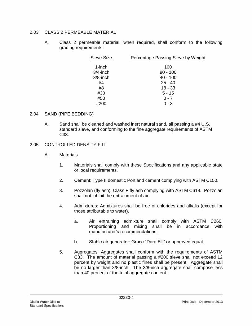
02230-4 Diablo Water District Print Date: December 2013 Standard Specifications
2.03 CLASS 2 PERMEABLE MATERIAL
A. Class 2 permeable material, when required, shall conform to the following grading requirements:
Sieve Size Percentage Passing Sieve by Weight
1-inch 100 3/4-inch 90 - 100 3/8-inch 40 - 100
#4 25 - 40 #8 18 - 33
#30 5 - 15 #50 0 - 7 #200 0 - 3
2.04 SAND (PIPE BEDDING)
A. Sand shall be cleaned and washed inert natural sand, all passing a #4 U.S. standard sieve, and conforming to the fine aggregate requirements of ASTM C33.
2.05 CONTROLLED DENSITY FILL
A. Materials
1. Materials shall comply with these Specifications and any applicable state or local requirements.
2. Cement: Type II domestic Portland cement complying with ASTM C150.
3. Pozzolan (fly ash): Class F fly ash complying with ASTM C618. Pozzolan shall not inhibit the entrainment of air.
4. Admixtures: Admixtures shall be free of chlorides and alkalis (except for those attributable to water).
a. Air entraining admixture shall comply with ASTM C260. Proportioning and mixing shall be in accordance with manufacturer’s recommendations.
b. Stable air generator: Grace “Dara Fill” or approved equal.
5. Aggregates: Aggregates shall conform with the requirements of ASTM C33. The amount of material passing a #200 sieve shall not exceed 12 percent by weight and no plastic fines shall be present. Aggregate shall be no larger than 3/8-inch. The 3/8-inch aggregate shall comprise less than 40 percent of the total aggregate content.
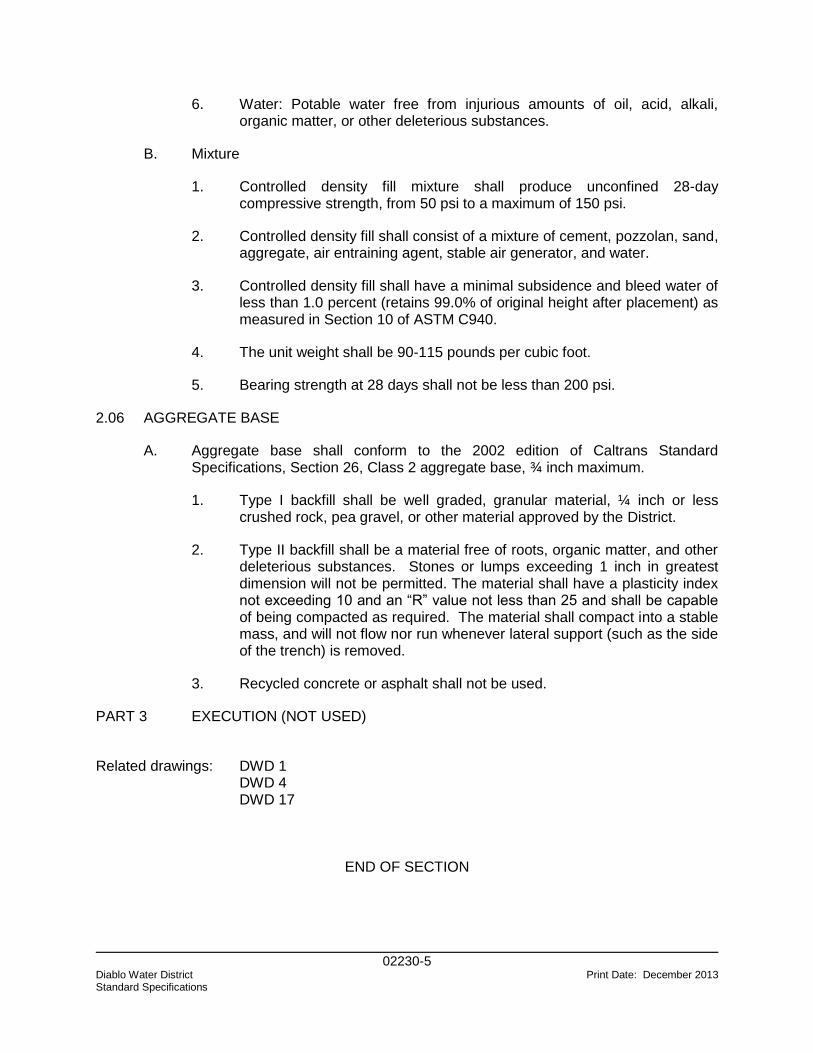
02230-5 Diablo Water District Print Date: December 2013 Standard Specifications
6. Water: Potable water free from injurious amounts of oil, acid, alkali, organic matter, or other deleterious substances.
B. Mixture
1. Controlled density fill mixture shall produce unconfined 28-day compressive strength, from 50 psi to a maximum of 150 psi.
2. Controlled density fill shall consist of a mixture of cement, pozzolan, sand, aggregate, air entraining agent, stable air generator, and water.
3. Controlled density fill shall have a minimal subsidence and bleed water of less than 1.0 percent (retains 99.0% of original height after placement) as measured in Section 10 of ASTM C940.
4. The unit weight shall be 90-115 pounds per cubic foot.
5. Bearing strength at 28 days shall not be less than 200 psi.
2.06 AGGREGATE BASE
A. Aggregate base shall conform to the 2002 edition of Caltrans Standard Specifications, Section 26, Class 2 aggregate base, ¾ inch maximum.
1. Type I backfill shall be well graded, granular material, ¼ inch or less crushed rock, pea gravel, or other material approved by the District.
2. Type II backfill shall be a material free of roots, organic matter, and other deleterious substances. Stones or lumps exceeding 1 inch in greatest dimension will not be permitted. The material shall have a plasticity index not exceeding 10 and an “R” value not less than 25 and shall be capable of being compacted as required. The material shall compact into a stable mass, and will not flow nor run whenever lateral support (such as the side of the trench) is removed.
3. Recycled concrete or asphalt shall not be used.
PART 3 EXECUTION (NOT USED)
Related drawings: DWD 1 DWD 4 DWD 17
END OF SECTION
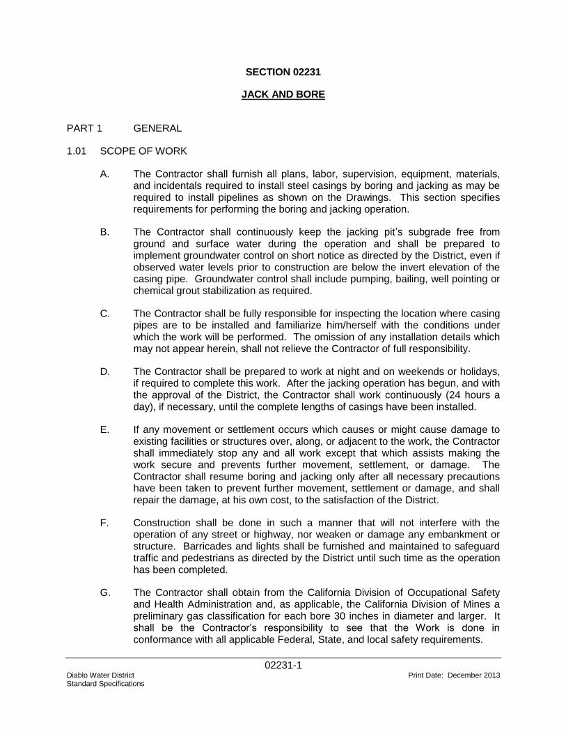
02231-1 Diablo Water District Print Date: December 2013 Standard Specifications
SECTION 02231
JACK AND BORE PART 1 GENERAL
1.01 SCOPE OF WORK
A. The Contractor shall furnish all plans, labor, supervision, equipment, materials, and incidentals required to install steel casings by boring and jacking as may be required to install pipelines as shown on the Drawings. This section specifies requirements for performing the boring and jacking operation.
B. The Contractor shall continuously keep the jacking pit’s subgrade free from ground and surface water during the operation and shall be prepared to implement groundwater control on short notice as directed by the District, even if observed water levels prior to construction are below the invert elevation of the casing pipe. Groundwater control shall include pumping, bailing, well pointing or chemical grout stabilization as required.
C. The Contractor shall be fully responsible for inspecting the location where casing pipes are to be installed and familiarize him/herself with the conditions under which the work will be performed. The omission of any installation details which may not appear herein, shall not relieve the Contractor of full responsibility.
D. The Contractor shall be prepared to work at night and on weekends or holidays, if required to complete this work. After the jacking operation has begun, and with the approval of the District, the Contractor shall work continuously (24 hours a day), if necessary, until the complete lengths of casings have been installed.
E. If any movement or settlement occurs which causes or might cause damage to existing facilities or structures over, along, or adjacent to the work, the Contractor shall immediately stop any and all work except that which assists making the work secure and prevents further movement, settlement, or damage. The Contractor shall resume boring and jacking only after all necessary precautions have been taken to prevent further movement, settlement or damage, and shall repair the damage, at his own cost, to the satisfaction of the District.
F. Construction shall be done in such a manner that will not interfere with the operation of any street or highway, nor weaken or damage any embankment or structure. Barricades and lights shall be furnished and maintained to safeguard traffic and pedestrians as directed by the District until such time as the operation has been completed.
G. The Contractor shall obtain from the California Division of Occupational Safety and Health Administration and, as applicable, the California Division of Mines a preliminary gas classification for each bore 30 inches in diameter and larger. It shall be the Contractor’s responsibility to see that the Work is done in conformance with all applicable Federal, State, and local safety requirements.
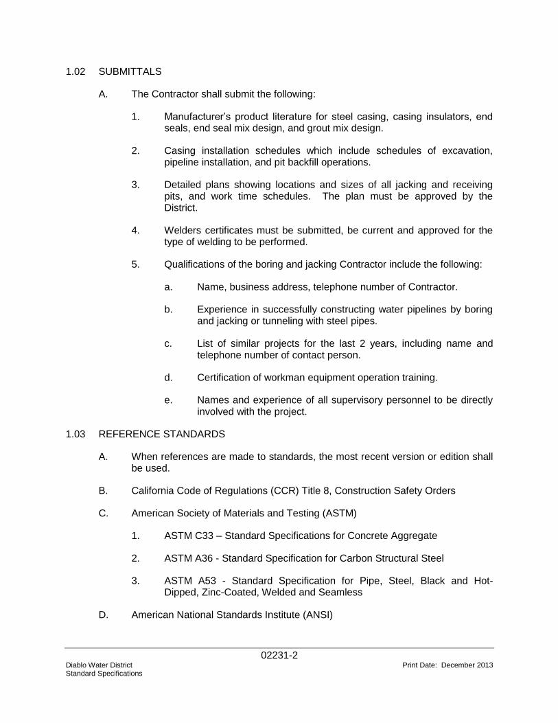
02231-2 Diablo Water District Print Date: December 2013 Standard Specifications
1.02 SUBMITTALS
A. The Contractor shall submit the following:
1. Manufacturer’s product literature for steel casing, casing insulators, end seals, end seal mix design, and grout mix design.
2. Casing installation schedules which include schedules of excavation, pipeline installation, and pit backfill operations.
3. Detailed plans showing locations and sizes of all jacking and receiving pits, and work time schedules. The plan must be approved by the District.
4. Welders certificates must be submitted, be current and approved for the type of welding to be performed.
5. Qualifications of the boring and jacking Contractor include the following:
a. Name, business address, telephone number of Contractor.
b. Experience in successfully constructing water pipelines by boring and jacking or tunneling with steel pipes.
c. List of similar projects for the last 2 years, including name and telephone number of contact person.
d. Certification of workman equipment operation training.
e. Names and experience of all supervisory personnel to be directly involved with the project.
1.03 REFERENCE STANDARDS
A. When references are made to standards, the most recent version or edition shall be used.
B. California Code of Regulations (CCR) Title 8, Construction Safety Orders
C. American Society of Materials and Testing (ASTM)
1. ASTM C33 – Standard Specifications for Concrete Aggregate
2. ASTM A36 - Standard Specification for Carbon Structural Steel
3. ASTM A53 - Standard Specification for Pipe, Steel, Black and Hot-Dipped, Zinc-Coated, Welded and Seamless
D. American National Standards Institute (ANSI)
02231-3 Diablo Water District Print Date: December 2013 Standard Specifications
1. ANSI/AWS D1.1 – Structural Welding Code – Steel
E. AMERICAN WATER WORKS ASSOCIATION
1. AWWA C206 – Field Welding of Steel Water Pipe
2. AWWA C213 – Fusion-Bonded Epoxy Coating for Interior and Exterior of Steel Water Pipes
1.04 QUALITY ASSURANCE
A. All boring and jacking operations shall be done by a qualified Contractor with at least 5 years of experience involving work on steel lining installation in jacking and boring tunnels.
B. The Contractor’s design engineer shall be a registered civil or structural engineer in California with at least 5 years of experience in design of boring and jacking or tunneling operations with steel pipe.
C. The Contractor’s superintendent in charge of work shall have a minimum of 2 projects of equivalent size and complexity within the past 7 years.
D. The Contractor’s supervising field welder and inspector shall have a minimum of 3 years recent experience within the last 5 years with welding procedures required on this project.
E. Welders shall be qualified under the provisions of ANSI/AWS D1.1. by an independent local, approved testing agency not more than 6 months prior to commencing work on the casing or pipeline. Machines and electrodes similar to those used in the Work shall be used in qualification tests. The Contractor shall furnish all materials and bear the expense of qualifying welders.
F. All welding procedures used to fabricate and install steel casings shall be prequalified under the provisions of ANSI/AWS D1.1. Welding procedures shall be required for, but not necessarily limited to, longitudinal and girth or special welds for pipe cylinders, casing joint welds, reinforcing plates, and pressure grout coupling connections.
PART 2 PRODUCTS
2.01 MATERIALS
A. Steel casings shall be fabricated in accordance with ASTM A53 from steel plates having minimum yield strength of 36,000 psi and meeting the requirements of ASTM A36, and shall be epoxy coated in accordance with AWWA C213. Steel casing sleeves shall be of the diameter and thickness identified in the Drawings, and shall be furnished complete with welded joint ends that are watertight, and for pipes 24 inches and larger, pressure grout couplings. The Contractor, at his/her own expense, may select a greater diameter or thickness for the method of work and loadings involved, site conditions, and possible interferences.
02231-4 Diablo Water District Print Date: December 2013 Standard Specifications
B. Mortar grout shall consist of one part Portland cement and two parts sand, and minimum amount of water to obtain the desired consistency. The grout mixtures shall contain 2 percent of bentonite by weight of the cement. Portland cement and water shall be as specified in Section 03600. Sand shall be of such fineness that 100 percent will pass a No. 8 sieve and at least 45 percent will pass a No. 40 sieve. Bentonite shall be commercially processed powdered bentonite, Wyoming type.
C. Sand for casing fill shall meet the requirements of ASTM C33 for fine aggregates.
D. Casing spacer insulators shall be Calpico Model W, or Williamson M-2. The spacer insulator "system" shall be designed and fabricated for the specific project and application for which they are furnished, including installation of carrier pipe in liner plate casing tunnels. All bands and other hardware on the spacers shall be Type 304 stainless steel. Insulator spacing shall be as indicated on the Drawings.
E. Casing End Closures
1. Mortar shall be Burke non-ferrous, non-shrink grout, or equal, with pea gravel.
2. Pre-fabricated rubber and seals may be used with the District’s approval.
PART 3 EXECUTION
3.01 JACKING PITS
A. The location of jacking pits shall be approved by the District.
B. All jacking pits shall be protected with suitable fencing or barricades to prohibit unauthorized access to the work site.
C. The pits shall be shaped with heavy timber or steel sheet piling or other suitable materials that shall be of adequate strength. Braced steel or heavy timber sheeting shall be used to support the sides of the excavation for the pits.
D. The Contractor shall furnish, install and remove, to the extent required, thrust blocks or whatever provisions may be required for driving the casings/sleeves and pipes forward.
E. Steel rails or beams embedded in concrete shall be used in the pit for placement and alignment of each piece of casing/sleeve or pipe during installation operations.
F. The Contractor shall be fully responsible for the removal of the pits, including the breaking-up, removing, and disposing of concrete, if so required, or cutting-off of sheeting and furnishing and placing the backfill to the normal subgrade as may be required following the installation operations.
02231-5 Diablo Water District Print Date: December 2013 Standard Specifications
G. The pits or trenches excavated to perform boring, tunneling and jacking operations shall be backfilled and compacted per Section 02210 immediately after jacking, pipe installation, grouting and filling has been completed.
H. The Contractor shall provide fans, blowers or other devices necessary to ensure adequate ventilation for workers in the casing, tunnel or boring excavations.
I. The Contractor shall provide adequate lighting devices and generator sets as necessary for workers and inspectors in the casing, tunnel and boring excavations.
3.02 BORING
A. A true, circular tunnel shall be cut to the required line and grade. Bored tunnels shall be no more than 4 inches larger than the outside diameter of the casing pipe to be installed.
B. Excavated material shall be placed at a distance from the working pit and used as backfill upon completion of casing and carrier pipe installation. The use of water or other fluids in connection with the boring operation will be permitted only to the extent necessary to lubricate cuttings. Water jetting will not be permitted.
C. Where material in the bore is sandy or unstable and will be subject to caving, the casing hole shall be bored and cased simultaneously, and the bored material removed through the casing. The cutting face of auger or drill shall not project more than 6 inches ahead of casing.
D. Where material in the bore is stable and not subject to caving, the hole for the casing may be bored first and casing jacked into the hole immediately after completion of boring if permitted by the District.
3.03 JACKING OPERATIONS
A. Heavy duty jacks suitable for forcing the casing or carrier pipe through the embankment or casing pipe opening shall be provided. In operating jacks, even pressure shall be applied to all jacks used. A suitable jacking head of timber, and suitable bracing between jacks and jacking head shall be provided so that pressure will be applied to the casing or carrier pipe uniformly around the ring of the casing or carrier pipe. A suitable jacking frame or back stop shall be provided. The casing or carrier pipe to be jacked shall be set on guides, properly braced together to support the section of the casing or carrier pipe and to direct it in the proper line and grade. The whole jacking assembly shall be placed so as to line up with the direction and grade of the casing pipe.
B. The casing or carrier pipe shall be jacked from the low or downstream end. The maximum deviation of casing pipe from the grade and line shown on the Drawings shall be such that the line and grade of the carrier pipe can be adjusted within the casing pipe and still maintain the line and grade along its full length. Carrier pipe shall not deviate more than 0.33 feet per 100 feet from the line and grade shown, provided that such variation shall be regular and continuous only
02231-6 Diablo Water District Print Date: December 2013 Standard Specifications
(no bows or reverse curve sections) in one direction and that the final grade of flow line shall be in the direction indicated on the Drawings.
C. When jacking of casing pipe is initiated, the operation shall be continued without interruption, insofar as practicable, to prevent the pipe from becoming firmly set in the embankment.
D. Excavated materials shall be removed from the casing as the boring or jacking operation progresses and no accumulation of excavated materials within the casing shall be permitted.
E. Any casing or carrier pipe damaged in jacking operations shall be removed and replaced by the Contractor at his expense.
F. Steel casing sections shall be field butt welded in accordance with the applicable portions of AWWA C206 and AWS D7.0 for field welded water pipe joints. The welded joints shall be wire brushed and painted with Koppers Inertol Quick-Drying Primer 626 primer manufactured by Tnemec Company Inc., or approved equal.
3.04 GROUTING
A. All space between the casing pipe and the bored excavation shall be pressure filled with grout immediately upon the complete installation of the casing.
B. Casing sleeves for jacking shall have grout holes equipped with pipe half-couplings. The 2 inch standard pipe half-couplings welded into the holes in the casing walls shall be filled with threaded cast iron bolt plugs. Bolt plugs shall be no less than 5/8 inch diameter. Three grout holes spaced at 120 degrees on center shall be installed with each set of three being not more than 10 feet apart along the casing. Shop drawings showing details of the casings, size and length of bolts, section modulus in inches cubed per inch of width and pipe thickness shall be furnished by the Contractor for review by the District.
C. Systems of standard pipe, fittings, hose and special grouting outlets, embedded in the sleeve walls shall be provided by the Contractor. Care shall be taken to insure that all parts of the system are maintained free from dirt. Cement grout shall be forced under pressure into the grouting connections. Grouting shall be started in the lowest connections and shall proceed until grout begins to flow from upper connections.
D. Apparatus for mixing and placing grout shall be of type approved by the District and shall be capable of mixing effectively and stirring the grout and then forcing it into the grout connections in a continuous uninterrupted flow.
E. After grouting is complete, pressure shall be maintained by means of stop cocks, or other suitable devices, until the grout has set sufficiently. After the grout is set, grout holes shall be completely filled with dense concrete and finished neatly without evidence of voids or projections.
02231-7 Diablo Water District Print Date: December 2013 Standard Specifications
3.05 INSTALLING CARRIER PIPE
A. After the casing has been completely installed, the Contractor shall thoroughly clean the interior of the casing. Contractor shall place the carrier pipe within the casing using casing spacer insulators. These methods, or modifications thereof, as approved by the District, shall be employed for the construction of all cased crossings.
B. After the carrier pipe is installed within the casing and prior to the placement of sand fill or grout, the Contractor shall conduct the required pressure and leakage test on the carrier pipe. Any leaks which are discovered during the testing phase shall be repaired to the satisfaction of the District.
C. The carrier pipe shall be installed to the exact line and grade required within the casing, and, after it has been satisfactorily placed and approved by the District, the space between the outside of the pipe and the casing shall be completely filled with sand blown in one continuous uninterrupted operation in a manner to prevent occurrence of any voids between carrier pipe and casing. Each joint of carrier pipe must be braced to sides and top of casing to prevent flotation or motion during the placing of sand. The casing spacer insulators shall be installed on the carrier pipe per the manufacturer's instructions prior to inserting the carrier pipe into the casing. Altered insulators shall not be used.
D. The annular space at each end of the casing shall be packed with mortar to seal the casing. The mortar closure shall extend a minimum of 12 inches into the casing. If approved by the District, a rubber casing seal may be used to close the ends of the casing.
3.06 PERMANENT MARKING
A. Contractor shall place permanent markers or signs at the ends of the casing pipe indicate the location of the buried pipeline.
Related drawings: DWD 5
END OF SECTION

02512-1 Diablo Water District Print Date: December 2013 Standard Specifications
SECTION 02512
STEEL PIPE AND FABRICATED SPECIALS PART 1 GENERAL
1.01 SCOPE OF WORK
A. The Contractor shall provide all materials, equipment, and labor and supervision necessary to furnish and install cement mortar lined and coated steel pipe and specials, complete and operable, including all connections as shown on the Drawings and as specified herein.
B. Specials are defined as fittings, closure pieces, correction pieces, bends, reducers, nozzles, wyes, tees, crosses, outlets, manifolds and other steel plate specials.
C. All steel pipe shall be cathodically protected per Section 16640 and the Drawings.
D. Connections to existing steel spiral wrapped pipe shall be designed by a registered Civil Engineer and submitted to the District for review.
1.02 REFERENCE SPECIFICATIONS, CODES, AND STANDARDS
A. Referenced standards shall be the most recent version or edition.
AASHTO Standard Specifications for Highway Bridges.
ANSI/AWS D1.1 Structural Welding Code Steel Thirteenth Edition (AWS).
ASTM A 36 Specification for Structural Steel.
ASTM A 139 Specification for Electric-Fusion (Arc)-Welded Steel Pipe
(NPS 4-in. and Over).
ASTM A 283 Specification for Low and Intermediate Tensile Strength
Carbon Steel Plates.
ASTM A 570 Specification for Steel, Sheet and Strip, Carbon, Hot-Rolled,
Structural Quality.
ASTM A 572 Specification for High-Strength Low-Alloy Columbian-
Vanadium Structural Steel.
ASTM C 150 Specification for Portland Cement.
ASTM E 165 Practice for Liquid Penetrant Inspection Method.
AWWA C200 Standard for Steel Water Pipe - 6-In. (150 mm) and Larger.
AWWA C205 Standard for Cement-Mortar Protective Lining and Coating for
Steel Water Pipe - 4-In. and Larger - Shop Applied.
AWWA C206 Standard for Field Welding of Steel Water Pipe.
02512-2 Diablo Water District Print Date: December 2013 Standard Specifications
AWWA C208 Standard for Dimensions for Fabricated Steel Water Pipe
Fittings.
AWWA C602 Standard for Cement-Mortar Lining of Water Pipelines-4-In.
(100 mm) and Larger - in Place.
AWWA MANUAL M 1 Steel Pipe - A Guide for Design and Installation.
1.03 CONTRACTOR SUBMITTALS
A. Shop Drawings: The Contractor shall submit shop drawings of pipe and fittings in accordance and the following supplemental requirements:
1. Joint and pipe fitting wall construction details which indicate the type and thickness of cylinder, the position, type, size and area of reinforcement, manufacturing tolerances, and all other pertinent information required for the manufacture of the product. Joint details shall be submitted where butt strap joints are required.
2. Fittings and special details such as elbows, wyes, tees, outlets, connections, test bulkheads, and nozzles or other specials where shown, which indicate amount and position of all reinforcement. All fittings and specials shall be properly designed to withstand the internal pressure, both circumferential and longitudinal, and the external loading conditions as indicated in the approved design calculations.
3. Design calculations including a complete stress analysis of each critical section of pipe wall, girth joints, and specials - all sufficient to ascertain conformance of pipe and fittings with these Specifications.
4. Material lists which include and describe all materials to be utilized.
5. Full and complete information regarding location, type, size and extent of all welds shall be shown on the shop drawings. The shop drawings shall distinguish between shop and field welds. Shop drawings shall indicate by welding symbols or sketches the details of the welded joints and the preparation of parent metal required to make them. Joints or groups of joints in which welding sequence or technique are especially important shall be carefully controlled to minimize shrinkage stresses and distortion.
B. Certificate of Compliance: Certificates of Compliance shall be provided for all products and materials proposed to be used under this Section, as specified in AWWA C200 and AWWA C205, respectively, and the following supplemental requirements:
1. Physical and chemical properties of all steel.
2. Hydrostatic test reports.
3. Results of production weld tests.
02512-3 Diablo Water District Print Date: December 2013 Standard Specifications
1.04 QUALITY ASSURANCE
A. Tests: Except as modified herein, all materials used in the manufacture of the pipe shall be tested in accordance with the requirements of AWWA C200 and AWWA C205, as applicable.
1. After the joint configuration is completed, each length of pipe of each diameter and pressure class shall be shop-tested and certified to a pressure of at least 80 percent of the yield strength of the pipe steel.
2. In addition to the tests required in AWWA C200, weld tests shall be conducted on each 5,000 feet of production welds and at any other times there is a change in the grade of steel, welding procedure, or welding equipment.
B. The District shall have the right to witness all testing conducted by the Contractor; provided, that the Contractor’s schedule is not delayed for the convenience of the District.
C. In addition to those tests specifically required, the District may request additional samples of any material including mixed concrete and lining and coating samples for testing by the District.
D. Welding Requirements: All welding procedures used to fabricate pipe shall be prequalified under the provisions of ANSI/AWS D1.1. Welding procedures shall be required for, but not necessarily limited to, longitudinal and girth or spiral welds for pipe cylinders, spigot and bell ring attachments, reinforcing plates and ring flange welds and plates for lug connections.
E. Welder Qualifications: All welding shall be done by skilled welders, welding operators and tackers who have had adequate experience in the methods and materials to be used. Welders shall be qualified under the provisions of ANSI/AWS D1.1 by an independent local, approved testing agency not more than 6 months prior to commencing work on the pipeline. Machines and electrodes similar to those used on the project shall be used in qualification tests.
PART 2 PRODUCTS
2.01 GENERAL
A. Steel pipe shall be cement mortar coated in accordance with AWWA C205. All linings and coatings shall be shop applied.
B. Steel pipe with mortar-lining and/or mortar-coating shall conform to AWWA C200 and AWWA C205, subject to the following supplemental requirements:
1. The pipe shall be of the diameter and class shown on the Drawings, shall be furnished complete with welded joints, and all specials and bends shall be provided as specified or required.
02512-4 Diablo Water District Print Date: December 2013 Standard Specifications
2. The inside diameter after lining shall not be less than the nominal diameter specified or shown.
C. Marking: The Contractor shall insure all pipes and specials are legibly marked in accordance with the laying schedule and marking diagram. Each pipe shall be numbered in sequence and said number shall appear on the laying schedule and marking diagram in its proper location for installation. All special pipe sections and fittings shall be marked at each end with top field centerline.
D. Laying Lengths: Maximum pipe laying lengths shall be 40 feet with shorter lengths provided as required by the design and Shop Drawings.
E. Offset Tolerances: For pipe wall thicknesses of 3/8 inch or less, the maximum radial offset (misalignment) for submerged arc and gas metal arc welded pipe shall be 0.1875 times the pipe wall thickness or 1/16 inch, whichever is larger. For pipe wall thickness of greater than 3/8 inch, the maximum radial offset shall be 0.1875 times the wall thickness or 5/32 inch, whichever is smaller.
F. Mortar Lining: The pipe mortar lining shall have smooth dense interior surfaces and shall be free from fractures, excessive interior surface crazing and roughness.
G. Bonding and Electrical Conductivity: All unwelded pipe joints shall be bonded for electrical conductivity in accordance with the approved cathodic protection system design. Insulated joints shall be provided as required by the approved cathodic protection system design.
H. Closure and Correction Pieces: Closure and correction pieces shall be provided as required so that closures may be made due to different headings in the pipe laying operation and so that correction may be made to adjust the pipe laying to conform to pipe stationing shown on the Drawings. Any change in location or number of said items must be approved by the District.
2.02 PIPE DESIGN
A. General: The pipe furnished shall consist of a steel cylinder, shop-lined with cement-mortar and shop-coated with an exterior coating of cement-mortar.
B. Design: Except as otherwise provided herein, materials, fabrication and shop testing of straight pipe shall conform to the requirements of AWWA C200, and shall conform to the dimensions of AWWA C208.
C. Pipe Dimensions: The pipe shall be of the diameter and class shown on the Drawings. Steel pipe dimensions represent the ultimate pipe inside diameter after lining.
D. Fitting Dimensions: The fittings shall be of the diameter and class shown on the Drawings.
E. Joint Design: Unless otherwise specifically required on the Drawings, the standard field joint for steel pipe shall be a split butt-strap joint. Flanged joints shall be
02512-5 Diablo Water District Print Date: December 2013 Standard Specifications
required where shown on the Drawings. The joints furnished shall have the same or higher pressure rating as the abutting pipe. All connections between steel and ductile iron pipe shall be electrically separated by an insulated flange or insulated mechanical coupling per Section 16640.
F. Restrained Joints: Where shown, restrained joints shall be field-welded joints. Designs shall include considerations of stresses induced in the steel cylinder, the joint rings and any field welds caused by thrust at bulkheads, bends, reducers and line valves resulting from the design working pressure. For field welded joints, design stresses shall not exceed 50 percent of the specified minimum yield strength of the grade of steel utilized, or 16,500 psi, whichever is less, for the part being examined when longitudinal thrust is assumed to be uniformly distributed around the circumference of the joint. At the Contractor’s option, the steel cylinder area may be progressively reduced from the point of maximum thrust to the end of the restrained length. All joints to be field welded for thrust restraint shall have the joint rings attached to the cylinder with double fillet welds.
2.03 FABRICATION AND MATERIALS
A. Cement: Cement for mortar shall conform to the requirements of AWWA C205; provided, that cement for mortar coating shall be Type V and mortar lining shall be Type II or V. Fly ash or pozzolan shall not be used as a cement replacement.
B. Steel for Cylinders and Fittings: Pipe manufactured under AWWA C200 shall be fabricated from sheet conforming to the requirements of ASTM A 570, Grades 30, 33, 36 or 40, or from plate conforming to the requirements of ASTM A 36; A 283, Grades C or D; or ASTM A 572, Grade 42 or coil conforming to the requirements of ASTM A 139, Grades B or C. All longitudinal and girth seams, whether straight or spiral, shall be butt welded using an approved electric-fusion-weld process.
C. All steel used for the fabrication of pipe shall have a maximum carbon content of 0.25 percent and shall have a minimum elongation of 22 percent in a 2-inch gage length.
D. Welding of Joint Rings to Resist Thrust: Where steel pipe with field-welded separate formed joint rings are used for thrust restraint, the joint rings shall be welded to the cylinder with double fillet welds.
2.04 PIPE FITTINGS AND SPECIALS
A. General: Reinforcement for closure and correction pieces, bends, reducers, nozzles, wyes, tees, crosses, outlets, manifolds and other steel plate specials shall be designed in accordance with AWWA Manual M-11. Reinforcement shall be designed for the design pressure specified or shown and shall be in accordance with the design details shown. Specials and fittings shall be equal in pressure design strength and shall have the same lining and coating as the adjoining pipe. Unless otherwise shown, the minimum radius of elbows shall be 2.5 times the pipe diameter and the maximum miter angle on each section of the elbow shall not exceed 11-1/4 degrees.
02512-6 Diablo Water District Print Date: December 2013 Standard Specifications
B. All threaded outlets shall be forged steel suitable for 3,000 psi service per ASTM A105 or ASTM A216, and shall be as manufactured by Bonnie Forge Co., "Threadolet," Allied Piping Products Co., "Branchlet" or equal.
C. Moderate deflections and long radius curves may be made by means of beveled joint rings, by pulling standard joints, by using short lengths or pipe, or a combination of these methods; provided that pulled joints shall not be used in combination with bevels. The maximum total allowable angle for beveled joints shall be 5 degrees per pipe joint. Bevels shall be provided on the bell ends. Mitering of the spigot ends will not be permitted. The maximum allowable angle for pulled joints shall be in accordance with the manufacturer's recommendations or the angle which results from a 3/4 inch pull out from normal joint closure, whichever is less. All horizontal deflections or fabricated angles shall fall on the alignment. In congested areas or at locations where underground structures are encountered, the chord produced by deflecting the pipe shall be no further than 6 inches from the alignment shown.
D. All vertical deflections shall fall on the alignment and at locations adjacent to underground obstructions, points of minimum earth cover, and pipeline outlets and structures, the pipe angle points shall match the angle points shown.
E. Outlets, Nozzles, Tees, Wyes, and Crosses: All outlets 12 inch and smaller may be fabricated from Schedule 30 or heavier steel pipe in the standard outside diameters, i.e., 12-3/4 inch, 10-3/4 inch, 8-5/8 inch, 6-5/8 inch, and 4-1/2 inch.
F. The design of outlet reinforcement shall be in accordance with the procedures given in Chapter 13 of AWWA Manual M-11, except that the design pressure, P, used in the AWWA Manual M-11 procedure shall equal the greater of 1.25 Pw or 0.9375 Pt. Unless otherwise shown outlets 2 inches in diameter and smaller, Weld-O-Let as specified in Section 15105, "Miscellaneous Piping, Valves, Fittings and Appurtenance," need not be reinforced.
G. In lieu of saddle or wrapper reinforcement as provided by the design procedure in AWWA Manual M-11, pipe or specials with outlets may be fabricated in their entirety of steel plate having a thickness equal to the sum of the pipe wall plus the required reinforcement.
H. Where required by the AWWA Manual M-11 design procedure crotch plate reinforcement shall be furnished.
I. Steel Welded Fittings: Steel welded fittings shall conform to ASTM A234.
J. Ends for Mechanical-Type Couplings: Except as otherwise provided herein, where mechanical-type couplings are indicated, the ends of pipe shall be banded with Type C collared ends using double fillet welds.
02512-7 Diablo Water District Print Date: December 2013 Standard Specifications
2.05 CEMENT MORTAR LINING
A. Cement-Mortar Lining for Shop Application: Except as otherwise specified, interior surfaces of all steel pipe, fittings, and specials shall be cleaned and lined in the shop with cement-mortar lining applied centrifugally in conformity with AWWA C205. If a special cannot be lined centrifugally, it shall be lined by hand. During the lining operation and thereafter, the pipe shall be maintained in a round condition by suitable bracing or strutting.
B. The nominal lining thickness shall be in accordance with DWD5, DWD6, and DWD7. The pipe shall be designed for deflection using the nominal lining thickness.
C. The exterior of pipe ends shall be left bare where field joints occur per DWD5. Ends of the linings shall be left square and uniform. Feathered or uneven edges will not be permitted.
D. Defective linings shall be removed from the pipe wall and shall be replaced to the full thickness required. Defective linings shall be cut back to a square shoulder in order to avoid feather edged joints.
E. The progress of the application of mortar lining shall be regulated in order that all hand work, including the repair of defective areas is cured in accordance with the provisions of AWWA C205. Cement-mortar for patching shall be the same materials as the mortar for machine lining, except that a finer grading of sand and mortar richer in cement shall be used when field inspection indicates that such mix will improve the finished lining of the pipe.
F. Cement-Mortar Lining for Field Application: The materials and design of in-place cement-mortar lining shall be in accordance with AWWA C602 and the following supplementary requirements:
1. Admixtures shall contain no calcium chloride.
2. The minimum lining thickness shall be as specified for shop-applied cement-mortar lining and finished inside diameter after lining shall be as shown on the Drawings.
G. Protection of Pipe Lining: For all pipe and fittings with shop-applied cement-mortar linings, a polyethylene or other suitable bulkhead shall be provided on the ends of the pipe and on all special openings to prevent drying out of the lining. All bulkheads shall be substantial enough to remain intact during shipping and storage until the pipe is installed.
2.06 EXTERIOR COATING
A. All pipe for buried service, including bulkheads, shall be coated with cement-mortar coating, with thickness as shown on the Drawings and tolerances in conformance with AWWA C205. The coating shall be reinforced in accordance with AWWA C205.
02512-8 Diablo Water District Print Date: December 2013 Standard Specifications
PART 3 EXECUTION 3.01 INSTALLATION OF PIPE
A. When the pipe is being laid, it shall be turned and placed where possible, so that any slightly damaged coating portion will be on top. The damaged area shall be repaired. All interior or exterior damaged areas shall be repaired using materials and methods in accordance with AWWA C205.
B. Pipe shall be laid directly on the bedding material. No blocking will be permitted, and the bedding shall be such that it forms a continuous, solid bearing for the full length of the pipe. Excavations shall be made as needed to facilitate removal of handling devices after the pipe is laid. Bell holes shall be formed at the ends of the pipe to prevent point loading at the bells or couplings. Excavation shall be made as needed outside the normal trench width at field joints to permit adequate access to the joints for field connection operations and for application of coating on field joints.
C. Vertical or horizontal grade changes, where approved by the District, may be made by the deflection of joints or by the use of bevel adapters. In no case shall the deflection in the joint exceed the maximum deflection recommended by the pipe manufacturer. No joint shall be misfit any amount which will be detrimental to the strength and water tightness of the finished joint.
3.02 WELDED JOINTS
A. General: Field welded joints shall be in accordance with AWWA C206.
B. Where exterior welds are performed, adequate space shall be provided for welding and inspection of the joints.
C. Butt straps shall be a minimum of 6-inches wide, the same thickness as the pipe wall and shall provide for a minimum of 3/4-inch lap at each pipe joint.
D. To control temperature stresses, the unbackfilled joint areas of the pipe shall be shaded from the direct rays of the sun by the use of properly supported awnings, umbrellas, tarpaulins, or other suitable materials for a minimum period of 2 hours prior to the beginning of the welding operation and until the weld has been completed. Shading materials at the joint area shall not rest directly on the pipe but shall be supported to allow air circulation around the pipe. Shading of the pipe joints need not be performed when the ambient air temperature is below 45 degrees F.
E. Prior to the beginning of the welding procedure, any tack welds used to position the pipe during laying shall be removed. The weld shall then be made in accordance with AWWA C206. Where more than one pass is required, each pass except the first and final one shall be peened to relieve shrinkage stresses; and all dirt, slag, and flux shall be removed before the succeeding bead is applied.
02512-9 Diablo Water District Print Date: December 2013 Standard Specifications
F. As soon as practicable after welding of each joint, all field-welded joints shall be tested by the liquid penetrant inspection procedure conforming to the requirements of ASTM E 165 under Method "B" and "Leak Testing." All defects shall be chipped out, rewelded and retested. Upon retest, the repaired area shall show no leaks or other defects.
G. Following tests of the joint, the exterior joint spaces shall be coated, and interior linings shall be repaired in accordance with these specifications.
H. Qualifications of Procedures and Welders: All welding procedures used to install pipe shall be prequalified under provisions of ANSI/AWS D1.1. Welding procedures shall be required for field attachments and field welded joints. Copies of welders’ certificates shall be provided to the District.
3.03 JOINT COATING
A. General: The interior and exterior joint recesses shall be thoroughly wiped clean and all water, loose scale, dirt and other foreign material shall be removed from the inside surface of the pipe. Grout for joint coating shall be non-shrink grout as allowed by AWWA C205 and specified in Section 03600, "Grout."
3.04 INSTALLATION OF PIPE APPURTENANCES
A. Protection of Appurtenances: Where the joining pipe is concrete or coated with cement mortar, buried appurtenances shall be coated with a minimum thickness of one inch of cement mortar having one part cement to not more than 2 parts plaster sand.
B. Installation of Flanged Joints: Before the joint is assembled, the flange faces shall be thoroughly cleaned of all foreign material with a power wire brush. The gasket shall be centered and the connecting flanges drawn up watertight without unnecessarily stressing the flanges. All bolts shall be tightened in a progressive diametrically opposite sequence and torqued with a suitable, approved and calibrated torque wrench. All clamping torque shall be in conformance with the manufacturers printed recommendations and shall be applied to the nuts only.
C. All buried flanges shall be coated by a shop applied epoxy coating.
D. Insulated Joints: Insulated joints and appurtenant features shall be made by the Contractor as shown on the Drawings or as required by the approved cathodic protection system design. The Contractor shall exercise special care when installing these joints to prevent electrical conductivity across the joint. After the insulated joint is completed, an electrical resistance test will be performed by the Contractor and the results will be submitted to the District. Should the resistance test indicate a short circuit, the Contractor shall remove the insulating units to inspect for damages, replace all damaged portions and reassemble the insulating joint. The insulated joint shall then be retested to assure proper insulation.
E. Flexible Coupled Joints: When installing flexible couplings, care shall be taken that the connecting pipe ends, couplings and gaskets are clean and free of all dirt and foreign matter with special attention being given to the contact surfaces of the pipe, gaskets and couplings. The couplings shall be assembled and installed in
02512-10 Diablo Water District Print Date: December 2013 Standard Specifications
conformity with the recommendation and instruction of the coupling manufacturer. Sleeve type coupling shall conform to the requirements of Section 15100, "Valves and Appurtenances."
F. Wrenches used in bolting couplings shall be of a type and size recommended by the coupling manufacturer. Coupling bolts shall be tightened so as to secure a uniform annular space between the follower rings and the body of the pipe with all bolts tightened approximately the same amount. Diametrically opposite bolts shall be tightened progressively and evenly. Final tightening shall be done with a suitable, approved and calibrated torque wrench set for the torque recommended by the coupling manufacturer. All clamping torque shall be applied to the nut only.
G. Upon completion of the coupled joint, the coupling and bare metal of the pipe shall be cleaned, primed and epoxy coated.
H. Installation of warning tape shall be in conformance with the Drawings.
3.05 CORROSION CONTROL
A. Corrosion control shall be provided on all steel pipelines and shall conform to the requirements of Section 16640, “Corrosion Control Requirements.”
3.06 TESTING AND DISINFECTION
A. Field testing and disinfection of all steel pipe shall conform to the requirements of Section 02675, "Water Pipeline Testing and Disinfection."
Related drawings: DWD 5 DWD 6 DWD 7 END OF SECTION

02512-11 Diablo Water District Print Date: December 2013 Standard Specifications
This page intentionally left blank.
02610-1 Diablo Water District Print Date: December 2013 Standard Specifications
SECTION 02610
DUCTILE IRON PIPE AND FITTINGS PART 1 GENERAL
1.01 SCOPE OF WORK
A. Furnish all labor, materials, equipment and incidentals required, install, test, and disinfect ductile iron pipe and fittings. Provide thrust blocks and couplings as required to achieve a complete pipe system.
B. Where the word "pipe" is used, it shall refer to pipe, fittings, or appurtenances unless otherwise noted.
1.02 SUBMITTALS
A. Submit, shop drawings and product data required to establish compliance with the Section. Submittals shall include the following
1. Prior to shipment of pipe, submit a certified affidavit of compliance from the pipe manufacturer stating that the pipe, fittings, gaskets, linings and exterior coatings for this project have been manufactured and tested in accordance AWWA and ASTM standards and requirements specified herein.
1.03 REFERENCE STANDARDS
A. Referenced standards shall be the most recent version or edition.
B. American Society for Testing and Materials (ASTM)
1. ASTM A377 - Standard Index for Specifications for Ductile-Iron Pressure Pipe
2. ASTM C150 - Standard Specification for Portland Cement.
C. American National Standards Institute (ANSI)
1. ANSI B1.1 - Unified Inch Screw Threads (UN and UNR Thread Form).
2. ANSI B16.1 - Cast Iron Pipe Flanges and Flanged Fittings Classes 25, 125 and 250.
3. ANSI B18.2 - Square and Hex Bolts and Screws Inch Series Including Hex Cap Screws and Lag Screws.
D. American Water Works Association (AWWA)
1. AWWA C104 - Cement-Mortar Lining for Ductile-Iron Pipe and Fittings for
02610-2 Diablo Water District Print Date: December 2013 Standard Specifications
Water.
2. AWWA C105 - Polyethylene Encasement for Ductile-Iron Pipe Systems.
3. AWWA C110 - Ductile-Iron and Gray-Iron Fittings, 3-in Through 48-in (75mm Through 1219mm) for Water.
4. AWWA C111 - Rubber-Gasket Joints for Ductile-Iron Pressure Pipe and Fittings.
5. AWWA C115 - Flanged Ductile-Iron Pipe with Ductile-Iron or Gray-Iron Threaded Flanges.
6. AWWA C150 - Thickness Design of Ductile-Iron Pipe.
7. AWWA C151 - Ductile-Iron Pipe, Centrifugally Cast for Water.
8. AWWA C153 - Ductile-Iron Compact Fittings, 3 In. Through 64 In., for Water Service
9. AWWA C600 - Installation of Ductile-Iron Water Mains and Their Appurtenances.
10. AWWA C606 - Grooved and Shouldered Joints.
11. AWWA C651 - Disinfecting Water Mains.
1.04 QUALITY ASSURANCE
A. Each length of ductile iron pipe supplied for the project shall be hydrostatically tested at the point of manufacture to 500 psi for a duration of 10 seconds per AWWA C151. Testing may be performed prior to machining bell and spigot. Failure of ductile iron pipe shall be defined as any rupture of the pipe wall. Certified test results shall be furnished in duplicate to the District prior to time of shipment.
B. All ductile-iron pipe and fittings to be installed under this project shall be inspected and tested at the foundry as required by the standard specifications to which the material is manufactured. Furnish in duplicate to the District sworn certificates of such tests and their results prior to the shipment of the pipe.
C. All pipe and fittings to be installed under this Contract may be inspected at the plant for compliance with this Section by an independent testing laboratory selected by the District, at the District's expense.
D. Inspection of the pipe and fittings will also be made by the District or representative of the District after delivery. The pipe shall be subject to rejection at any time on account of failure to meet any of the specified requirements, even though sample pipes may have been accepted as satisfactory at the place of
02610-3 Diablo Water District Print Date: December 2013 Standard Specifications
manufacture. Pipe rejected after delivery shall be marked for identification and shall be removed from the job.
E. All pipe and fittings shall be permanently marked with the following information:
1. Manufacturer, date.
2. Size, type, class, or wall thickness.
3. Standard produced to (AWWA, ASTM, etc).
PART 2 PRODUCTS
2.01 MATERIALS
A. Pipe
1. Pipe shall be supplied in standard factory lengths for all pipe diameters.
2. Bell and spigot ductile iron pipe shall be Pressure Class 250, or greater, as per AWWA C150.
3. Flanged ductile iron pipe shall conform to AWWA C115 and C110. Four (4) inch flanged pipe shall be Thickness Class 51 as per AWWA C150, and flanged pipe sizes 6 through 24 inches shall be Thickness Class 50 as per AWWA C150.
4. Ductile iron pipe shall be as manufactured by U.S. Pipe and Foundry Company, Inc.; American Cast Iron Pipe Company; Clow Water System Company, Pacific States, or equal.
B. Joints
1. Ductile iron pipe shall have push-on, mechanical, locking, or flanged joints. Flange shall be flat face type, unless otherwise noted, meeting ANSI requirements, minimum Class 250.
2. Flange gasket shall be full face type per AWWA C111 to provide positive sealing for the flanged ductile iron joints. Gaskets shall be Garlock 3760-U only, no equal.
3. Flange assembly bolts shall be ASTM A193, 304 stainless steel, Grade B8 hex-head bolts, washers, and hexagon nuts. Bolts shall have “B8” stamped on the head. Threads shall conform to ANSI B1.1. Bolt length shall be such that after joints are assembled, the bolts shall protrude through the nuts, but not more than ½ inch.
4. Sleeve type couplings shall be Dresser Style 38 or 138 as manufactured by Dresser Industries or equal, with EPDM gaskets.
02610-4 Diablo Water District Print Date: December 2013 Standard Specifications
5. Flanged coupling adaptors shall be Smith-Blair Type 913 or equal, with EPDM gaskets.
6. Where restrained joints are specified on the plans, locking joints shall be Field Lok 350 by U.S. Pipe.
C. Fittings
1. Pipe fittings shall be ductile iron with a pressure rating of 250 psi. Fittings shall meet the requirements of AWWA C110 or AWWA C153 as applicable. Fittings shall have the same pressure rating, as a minimum, of the connecting pipe. Fittings shall be manufactured by Tyler, Sigma or Star.
D. Interior Lining
1. Ductile iron pipe and fittings shall have a cement mortar lining and asphaltic seal coat in accordance with AWWA C104.
E. Exterior Coatings
1. Unless otherwise specified, all coatings shall be shop applied with "hold-backs" provided as required at pipe and fitting ends for satisfactory installation for joint connections in the field. Provide all necessary coating materials to perform field coating applications at joints. Unless otherwise noted, field applied coating material shall be compatible with or equal to the shop applied material. Field repair of pipe with damaged coating shall receive prior approval of the District. If, in the opinion of the District that the coating damage is beyond repair the pipe shall be replaced. All flange bearing surfaces shall be uncoated.
F. All pipe shall be cathodically protected per Section 16640.
PART 3 EXECUTION
3.01 PIPE INSTALLATION
A. General
1. All piping and fittings shall be installed true to alignment. Thrust blocks or other anchorage shall be provided where required. Any damage to linings shall be repaired to the satisfaction of the District before the pipe is installed. Each length of pipe shall be cleaned out before installation. All of manufacturer's recommendations shall be complied with.
2. The deflection at joints shall not exceed the values stipulated in AWWA C600, unless specially designed bells and spigots are provided. Fittings, in addition to those shown on the Drawings, shall be provided, if required, in areas where conflict exists with the existing facilities.
02610-5 Diablo Water District Print Date: December 2013 Standard Specifications
3. When pipe cutting is acceptable to the District, the cutting shall be done by abrasive saw, leaving a smooth cut at right angles to the axis of the pipe. After cutting, the end of pipe shall be dressed with a file or power grinder to remove all roughness and sharp edges. Any damage to the lining shall be repaired to the satisfaction of the District.
4. Ductile iron and fittings shall be installed in accordance with requirements of AWWA C600 modified.
B. Jointing
1. Flanged joints shall be made using gaskets, bolts, bolt studs with a nut on each end, or studs with nuts where the flange is tapped. The number and size of bolts shall conform to the same ANSI Standard as the flanges.
2. Mechanical joints shall be carefully assembled in accordance with the manufacturer’s recommendations. If effective sealing is not obtained, the joint shall be disassembled, thoroughly cleaned, and reassembled. Bolts in flanged joints or mechanical joints shall be tightened alternately and evenly to torque values listed in Appendix A of ANSI/AWWA C111. Overtightening of bolts to compensate for poor installation practice will not be permitted.
3. Sleeve type couplings and grooved joints using split ring couplings shall be installed in accordance with the procedures recommended by their respective manufacturers.
4. For the installation of push-on joints, the pipe manufacturer’s instructions and recommendations for proper jointing operations shall be followed. All joint surfaces shall be lubricated with heavy vegetable soap solution immediately before the joint is completed. Lubricant shall be suitable for use in potable water, shall be stored in closed containers, and shall be kept clean. Each spigot end shall be suitably beveled to facilitate assembly.
5. All connections between ductile iron and steel pipe shall be electrically separated by an insulated flange or insulated mechanical coupling.
6. All pipe and appurtenances connected to equipment shall be supported in such a manner as to prevent any strain being imposed on the equipment. When manufacturers have indicated requirements that piping loads shall not be transmitted to their equipment, submit a certification stating that such requirements have been complied with.
3.02 CLEANING, TESTING, AND DISINFECTION
A. Testing and disinfection of all ductile iron pipe shall be per Section 02675.
END OF SECTION
_____ 02620-1 Diablo Water District Standard Specifications Print Date: December 2013
SECTION 02620 POLYVINYL CHLORIDE (PVC) PIPE AND FITTINGS PART 1 GENERAL
1.01 SCOPE OF WORK
A. The Contractor shall furnish all labor, supervision, materials, tools, equipment and incidentals required and install and test polyvinyl chloride (PVC) potable water, fittings, appurtenances and adapters as shown on the Drawings and as specified herein.
1.02 SUBMITTALS
A. The Contractor shall submit shop drawings, product data and design calculations for District’s review.
B. Shop drawings shall show layout and details of reinforcement, jointing, specials and fittings, connection to structures, method of manufacture and installation of pipe, material list of hardware to assemble pipe, and a schedule of pipe lengths (including the length of individual pipes by diameter) for the entire job.
C. Design calculations for the conditions specified in Paragraph 2.01 of this Section, shall be submitted with the shop drawings and shall include all formulas used in the calculations, all values of constants used in the formulas in accordance with ANSI/AWWA and ASTM reference standards.
D. Prior to shipment of pipe, the Contractor shall submit a certified affidavit of compliance from the manufacturer stating that the pipe, fittings, gaskets, coatings for this project have been manufactured and tested in accordance with ANSI/AWWA and ASTM standards and requirements specified herein.
E. Manufacturer’s recommendations for handling, storing and installation of pipe and fittings.
1.03 REFERENCE STANDARDS
A. Referenced standards shall be the most recent version or edition.
B. American Society for Testing and Materials (ASTM)
1. ASTM D1784 - Standard Specification for Rigid Poly (Vinyl Chloride) (PVC) Compounds and Chlorinated Poly (Vinyl Chloride) (CPVC) Compounds.
2. ASTM D3139 - Standard Specification for Joints for Plastic Pressure Pipes Using Flexible Elastomeric Seals.
_____ 02620-2 Diablo Water District Standard Specifications Print Date: December 2013
3. ASTM F477 - Standard Specification for Elastomeric Seals (Gaskets) for Joining Plastic Pipe.
C. American Water Works Association (AWWA)
1. AWWA C110 – Ductile-Iron and Gray-Iron Fittings, 3 In. through 48 In., for Water
2. AWWA C111 – Rubber Gasket Joints for Ductile-Iron Pressure Pipe and Fittings
3. AWWA C153 – Ductile-Iron Compact Fittings, 3 In. Through 64 In., for Water Service
4. AWWA C605 – Standard for Underground Installation Polyvinyl Chloride (PVC) Pressure Pipe and Fittings for Water
5. AWWA C900 – Standard for Polyvinyl Chloride (PVC) Pressure Pipe and Fabricated Fittings, 4-inch Through 12-inch, for Water Distribution
6. AWWA C905 – Standard for Polyvinyl Chloride (PVC) Pressure Pipe and Fabricated Fittings, 14-inch Through 48-inch, for Water Transmission
7. AWWA Manual No. 23 – PVC Pipe – Design and Installation
D. National Sanitation Foundation (NSF)
1. Standard No. 14 – Plastic Piping Components and Related Materials
2. Standard No. 61 – Drinking Water System Components - Health Effects
1.04 QUALITY ASSURANCE
A. All PVC pipe and ductile iron fittings shall be from single manufacturers. The supplier shall be responsible for the provisions of all test requirements specified in the referenced ASTM, AWWA and NSF Standards for the type of pipe used. The Contractor shall furnish the District certification of such tests and their results prior to the shipment of the pipe.
B. All pipe and fittings to be installed may be inspected at the plant for compliance with this Section by an independent testing laboratory provided by the District. The Contractor shall require the manufacturer's cooperation in these inspections. The pipe manufacturer shall be required to:
1. Have sufficient pipe made in advance so that a reasonable amount will be available at each plant inspection.
C. Inspection of the pipe and fittings will also be made by the District or other representatives of the District after delivery. The pipe shall be subject to rejection at any time on account of failure to meet any of the Specification requirements, even though sample pipes may have been accepted as
_____ 02620-3 Diablo Water District Standard Specifications Print Date: December 2013
satisfactory at the place of manufacture. Pipe rejected after delivery shall be marked for identification and shall be removed from the job.
D. Any PVC pipe showing evidence of UV degradation through discoloration will be rejected.
E. The following shall be continuously indent printed on the pipe or spaced at intervals not exceeding 5 feet:
1. Name and/or trademark of the pipe manufacturer.
2. Nominal pipe size.
3. Dimension ratio.
4. The letters PVC followed type of pipe.
5. Manufacturing standard reference, e.g., ASTM F679, or ASTM F789.
6. A production code from which the date and place of manufacture can be determined.
PART 2 PRODUCTS
2.01 DESIGN
A. The internal diameter of the pipe shall meet the stated internal diameter as shown on the Drawings.
B. Design for the net thickness for external loading shall be taken as the greater of the following conditions:
1. 3 feet of cover with AASHTO HS-20 wheel loads for two trucks passing with an impact factor of 1.5.
2. Depth from existing ground level or future proposed grade (whichever is greater) to top of pipe as shown on Drawings, with AASHTO HS-20 wheel loads for two trucks passing with an impact factor of 1.5.
3. Soil Density: 120 pounds per cubic foot.
4. Deflection lag factor: 1.00
5. Soil Modulus (E’): 1,500 psi
2.02 PVC PIPE AND FITTINGS FOR POTABLE WATER SERVICE
A. PVC pressure pipe sized 4 through 12 inches shall conform to the requirements of AWWA C900. All piping shall be Class 150 with a Dimension Ratio (DR) of 18.
_____ 02620-4 Diablo Water District Standard Specifications Print Date: December 2013
B. AWWA C900 Class 200 pipe shall be used in areas required by the State Department of Health Services for water mains paralleling and crossing sanitary sewers or when the depth of the main does not meet minimum requirements. The pipe shall be PVC 1120 made from PVC compounds Class 12454-A or 12454-B as defined in ASTM D1784. Each pipe length shall be marked with the manufacturer's name or trademark, size, material code, pressure class, AWWA designation number and seal of test agency that verified pipe material for potable-water service. Pressure class of Class 200 pipe shall be DR 14.
C. PVC pipe and associated fittings shall have bell and spigot push-on joints. Solvent welded joints will not be allowed. The bell shall consist of an integral wall section with a solid cross-section elastomeric gasket securely locked in place to prevent displacement during assembly. The performance of the elastomeric gasketed joint shall conform to ASTM D3139 and ASTM F477. All pipe shall have a “home” mark on the spigot end to indicate proper penetration when the joint is made.
D. All fittings and accessories for waterlines shall be ductile iron and shall conform to the requirements of AWWA C110 or AWWA C153 minimum Class 250. Fittings shall be push on, flanged, or mechanical joint and shall be lined and coated for potable water service.
1. Gaskets for push-on type joints shall be synthetic rubber and conform to AWWA C111.
2. Mechanical joint fittings shall not be used with PVC pipe unless prior approval is received from the District. Mechanical joint fittings shall incorporate a megalug restraint system, or other approved restraint system. Mechanical joint fittings shall be bitumastic lined and coated.
3. Mechanical couplings, where shown on the drawings, shall be long barrel type, Style 253 by Dresser Industries, or equal. Middle ring shall be a thickness equal to or greater than the thickness of the pipe wall. Couplings shall have EPDM gaskets, and shall be shop-coated with fusion bonded powder epoxy coating meeting requirements of NSF-61. The shop-coat shall be compatible with the final exterior coating system. Couplings shall be furnished complete. All sleeve couplings shall be harnessed unless otherwise noted. All nuts, bolts, and threaded rods shall be 304 stainless steel.
E. Potable water pipelines shall be by Vinyl Tech, Royal Group, or Northern, and blue in color. The standard length of pipe shall be 20 feet for all pipe diameters.
F. Ductile iron fittings shall be by Sigma, Tyler, or Star.
2.03 COPPER WIRE AND WARNING TAPE
A. All nonmetallic water mains shall include a continuous 12 gage, single-strand copper wire with blue insulation, taped to the top of the pipe and extended upwards into all valve boxes.
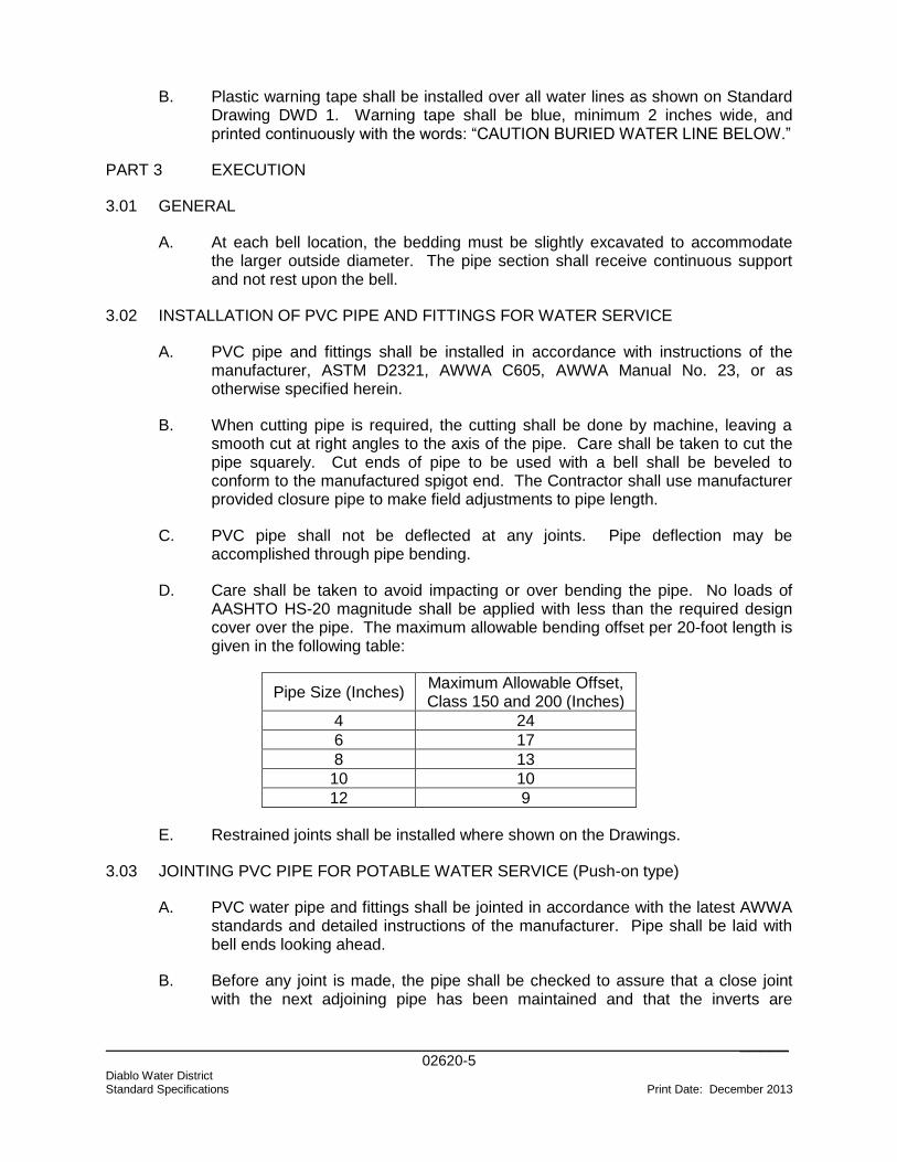
_____ 02620-5 Diablo Water District Standard Specifications Print Date: December 2013
B. Plastic warning tape shall be installed over all water lines as shown on Standard Drawing DWD 1. Warning tape shall be blue, minimum 2 inches wide, and printed continuously with the words: “CAUTION BURIED WATER LINE BELOW.”
PART 3 EXECUTION
3.01 GENERAL
A. At each bell location, the bedding must be slightly excavated to accommodate the larger outside diameter. The pipe section shall receive continuous support and not rest upon the bell.
3.02 INSTALLATION OF PVC PIPE AND FITTINGS FOR WATER SERVICE
A. PVC pipe and fittings shall be installed in accordance with instructions of the manufacturer, ASTM D2321, AWWA C605, AWWA Manual No. 23, or as otherwise specified herein.
B. When cutting pipe is required, the cutting shall be done by machine, leaving a smooth cut at right angles to the axis of the pipe. Care shall be taken to cut the pipe squarely. Cut ends of pipe to be used with a bell shall be beveled to conform to the manufactured spigot end. The Contractor shall use manufacturer provided closure pipe to make field adjustments to pipe length.
C. PVC pipe shall not be deflected at any joints. Pipe deflection may be accomplished through pipe bending.
D. Care shall be taken to avoid impacting or over bending the pipe. No loads of AASHTO HS-20 magnitude shall be applied with less than the required design cover over the pipe. The maximum allowable bending offset per 20-foot length is given in the following table:
Pipe Size (Inches) Maximum Allowable Offset, Class 150 and 200 (Inches)
4 24
6 17
8 13
10 10
12 9
E. Restrained joints shall be installed where shown on the Drawings.
3.03 JOINTING PVC PIPE FOR POTABLE WATER SERVICE (Push-on type)
A. PVC water pipe and fittings shall be jointed in accordance with the latest AWWA standards and detailed instructions of the manufacturer. Pipe shall be laid with bell ends looking ahead.
B. Before any joint is made, the pipe shall be checked to assure that a close joint with the next adjoining pipe has been maintained and that the inverts are
_____ 02620-6 Diablo Water District Standard Specifications Print Date: December 2013
matched and conform to the required grade. The pipe shall not be driven down to grade by striking it.
C. Bell/spigot joints will be assembled by inserting spigots into in-place bells. The gasket, spigot, and bell must be clean to ensure that the gasket is properly seated. Spigots and bells shall be generously lubricated with a vegetable-base lubricant supplied by the pipe manufacturer. The pipe spigot shall then be inserted into the bell in accordance with the manufacturer's recommendations.
D. Each length of the pipe shall be shoved home against the pipe previously laid and held securely until enough backfill has been placed to hold the pipe in place. Joints shall not be "pulled" or "cramped".
3.04 JOINTING MECHANICAL JOINT FITTINGS FOR POTABLE WATER SERVICE
A. Mechanical joints at valves, fittings and where designated shall be in accordance with the AWWA C111 and the instructions of the manufacturer. Suitable PVC to ductile iron adaptors shall be installed prior to installing fittings. PVC beveled spigot shall be cut flush prior to insertion in mechanical joint pipe. To assemble the joints in the field, thoroughly clean the joint surfaces and rubber gasket with soapy water before tightening the bolts. Bolts shall be tight to the specified torques. Bolts, nuts, and washers for flanges shall be 316 stainless steel. Under no condition shall extension wrenches or pipe over handle of ordinary ratchet wrench be used to secure greater leverage.
3.05 ACCEPTANCE TESTING
A. PVC pipes for pressure water system shall be tested and disinfected in accordance with Section 02675.
END OF SECTION
02675-1 Diablo Water District Print Date: December 2013 Standard Specifications
SECTION 02675 WATER PIPELINE TESTING AND DISINFECTION PART 1 GENERAL
1.01 SCOPE OF WORK
A. Furnish all labor, materials, equipment and incidentals required and test and clean all new potable water pipelines of 6 inches and greater installed under this Contract as specified herein. Chlorinate and perform bacteriological testing of all potable water lines, for all sizes, as detailed in this Section.
1.02 SUBMITTALS
A. Contractor shall submit the following to the District:
1. Test Records
a. Records shall be maintained of all tests performed.
b. Test records shall include:
i. Date of Testing
ii. Identification of Piping Tested
iii. Test Fluid
iv. Test Pressure
v. Signatures of Contractor and Construction Manager
2. If leaks are found, they shall be noted, on the record. After correction, perform retesting as specified for original test.
3. Records of test shall be maintained by the Contractor and six copies furnished to the District.
1.03 REFERENCE STANDARDS
A. Where references are noted, the most recent version or edition shall be used.
B. American Water Works Association
1. AWWA C600 – Installation of Ductile-Iron Water Mains and Their Appurtenances
2. AWWA C605 – Underground Installation of Polyvinyl Chloride (PVC) Pressure Pipe and Fitting for Water
02675-2 Diablo Water District Print Date: December 2013 Standard Specifications
3. AWWA C651 – Disinfecting Water Mains
PART 2 PRODUCTS
2.01 TEST EQUIPMENT
A. Hydrostatic Test (Pressure Pipes)
1. Water - From the District’s existing water system.
2. Pump – Install water meter in-line with pump to measure water use to maintain pressure.
3. Strainer - On inlet side of the pump to prevent foreign matter from entering the system.
4. Valves - Shall be provided on the suction and discharge side of the pump.
5. Relief Valve - Set at a pressure to relieve at 20 to 25 percent above the required test pressure.
6. Pressure Gage(s) - Capable of reaching 50 percent over the test pressure. These should be located at the pump discharge and any other place deemed convenient by the Contractor.
7. Pressure gages and relief valves shall be checked for accuracy before use in test procedures.
PART 3 EXECUTION
3.01 GENERAL
A. Furnish all necessary equipment and labor for cleaning, testing and chlorinating the pipelines. The procedures and methods shall be approved by the District.
B. Make any taps and furnish all necessary caps, plugs, etc, as required in conjunction with testing pipelines. Furnish a test pump, gauges and any other equipment required in conjunction with carrying out the hydrostatic tests.
C. Any connection between the new pipeline and the existing water system shall include a double-check valve assembly installed to prevent flow into the existing system. The double-check valve assembly shall be required until bacteriological sampling proves the new pipeline is properly disinfected. Only a DHS approved double-check valve passing the District’s backflow test shall be used by the Contractor.
D. After the completion of sufficient backfill, the newly laid pipe or any valve section thereof, shall be subjected to two hydrostatic pressure tests. One pressure test will be conducted prior to the placement of the subbase and/or base of the roadway. The second pressure test will be conducted immediately prior to
02675-3 Diablo Water District Print Date: December 2013 Standard Specifications
paving of the roadway or after one lift, but before the final lift, where more than one lift is to be used.
E. Any leaks, failures, or imperfect construction that develops during any test shall be repaired by the Contractor, and the test repeated until the system is proved satisfactory.
3.02 TESTING PRESSURE PIPELINES
A. This test specification shall be used to hydrostatically test piping systems for structural integrity and leaks as specified herein and in AWWA C600. The test shall be performed at ambient temperature unless otherwise specified.
B. Preparation for Test
1. Vents shall be provided at the high points of the system and drains provided where means of venting or draining do not exist.
2. Remove or block off, all relief valves, rupture discs, alarms, control instruments, etc. that shall not be subjected to the test pressure.
3. All discs, balls, or pistons from check valves shall be removed if they interfere with filling of the system. Open all valves between inlet and outlet of the section to be tested.
4. Connect pump and provide temporary closures for all of the external openings in the system. Use caution to insure that the closures are properly designed and strong enough to withstand the test pressure.
5. A joint previously tested in accordance with this specification may be covered or insulated.
6. Expansion joints shall be provided with temporary restraint for additional pressure under test or shall be isolated from the test.
7. Flanged joints, where blanks are inserted to isolate equipment during the test, need not be tested.
C. Test Procedures
1. Any connection between the new pipeline being installed and the existing water system shall include a state approved double-check valve assembly installed to prevent flow into the existing system. The device shall be tested by Diablo Water District prior to being made available to the new mains. Any devices that fail the test shall be repaired to the satisfaction of the District. The backflow device assembly shall be required until bacteriological sampling proves the new pipeline is properly disinfected. The contractor shall pay costs of all water used for construction purposes, including pipeline flushing and testing. The contractor is required to use a District furnished meter and to pay the

02675-4 Diablo Water District Print Date: December 2013 Standard Specifications
required deposit for meter use. District meters are 3-inch in size. The Contractor, at his expense, shall provide a larger meter if required to complete the work. Any meter, other than that furnished by the District, will require prior District approval.
2. The test section shall be slowly filled with potable water. Open vents to allow displacement of all entrapped air. For all pipelines exceeding 500 feet in length, the maximum rate of filling shall be limited to that which produces a maximum nominal flow velocity of one foot per second in the pipe to be tested.
3. Close vents and restrict personnel in the test area to those involved in the test.
4. Raise the pressure slowly with the pump until the predetermined test pressure is reached. Maintain pressure for four hours keeping personnel at a safe distance.
5. Reduce the pressure about 20 percent and hold it at that point while the entire system is carefully inspected for leaks, cracks, or other signs of defects. No leakage will be permitted for any pipe being tested.
6. If any leaks, failures or imperfect construction that develops during any test are found, the pressure shall be released, and the system drained. The defects shall be corrected by the Contractor, and the test repeated.
7. After a satisfactory test has been completed, the line shall be drained.
D. Testing of PVC Pipe
1. The duration of the test shall be four hours and the pipe shall be subjected to a hydrostatic pressure of 50 percent above the normal operating pressure, or 150 pounds per square inch, whichever is greater. In no case shall the test pressure be allowed to exceed the design pressure for pipe, appurtenances, or thrust restraints. No leakage will be permitted.
E. Testing of Ductile Iron Pipe
1. The duration of the test shall be four hours and the pipe shall be subjected to a hydrostatic pressure of 50 percent above the normal operating pressure, or 150 pounds per square inch, whichever is greater. In no case shall the test pressure be allowed to exceed the design pressure for pipe, appurtenances, or thrust restraints. No leakage will be permitted.
F. Testing of Steel Pipe
1. All pipelines shall be tested by subjecting each section to a pressure, measured at the lowest end of the section, of at least 150 percent of the
02675-5 Diablo Water District Print Date: December 2013 Standard Specifications
class rating or design pressure of pipe under test. In no case shall the pipe be tested at less than 150 pounds per square inch, nor shall the test pressure be allowed to exceed the design pressure for pipe, appurtenances, or thrust restraints. No leakage will be permitted.
2. The test may be made before or after backfilling. However, if mechanical compaction is to be used in the backfilling operations as spelled out in AWWA C600, the test shall not be made until the backfilling is completed and compacted. All connections, blowoffs, hydrants, and valves shall be tested with the main as far as is practicable.
G. The pressure test on mortar-lined pipe shall not begin until the pipe has been filled with water for at least 24 hours to allow for absorption in the cement mortar lining.
3.03 CLEANING
A. At the conclusion of the work, thoroughly clean all pipelines by flushing with water or other means to remove all dirt, stones, pieces of wood, or other material which may have entered the pipes during the construction period. Debris cleaned from the lines shall be removed from the low end of the pipeline. If after this cleaning, obstructions remain, they shall be removed. After the pipelines are cleaned and if the groundwater level is above the pipe or following a heavy rain, the Engineer will examine the pipes for leaks. If any further defective pipes or joints are discovered, the Contractor shall repair them. Finished paving shall not be installed prior to completion of all cleaning and testing.
3.04 DISINFECTION OF PIPELINES
A. After completion of the hydrostatic test, the mains shall be thoroughly flushed with a minimum pipe velocity of 2.5 fps and chlorinated in accordance with the latest revision of AWWA 651, Standards of Disinfecting Water Mains. Any one of the methods therein described may be used, with the additional requirement of 50 ppm chlorination minimum initial application. At the end of the contact period, the mains shall again be flushed, and bacteriological samples taken by the District.
B. If necessary, the Contractor shall provide, at his expense, outlets from which to take the samples. The location of the chlorination and sampling points will be determined by the District in the field. Taps for chlorination and sampling shall be installed. The Contractor shall uncover and backfill the taps as required.
C. Disinfection of tie-ins shall be performed by the Contractor by swabbing with chlorine or by other approved methods. Following a tie-in, the area affected by the tie-in shall be thoroughly flushed and bacteriological samples will be taken by the District as deemed necessary.
D. All treated water flushed from the lines shall be dechlorinated and disposed of by discharging to the locations identified in the Drawings, or by other approved
02675-6 Diablo Water District Print Date: December 2013 Standard Specifications
means. No discharge of chlorinated water to any storm sewer or natural water course will be allowed, unless properly dechlorinated.
E. The Contractor shall rechlorinate and retest any lines that do not meet the requirements of the above testing. The line shall not be placed in service until the requirements of the State Public Health Department are met.
3.05 BACTERIOLOGICAL TESTING
A. The District shall take water samples for bacteriological testing for approximately every 600 feet of water main, with a minimum of two samples and one sample from each dead end. After the samples have passed the bacteriological testing, the Contractor will be notified and arrangements can be made to make tie-ins and connections to house services. Each water sample will have passed the bacteria tests if they show zero total coliform per 100 ml and not more than 50 nonsheen bacteria per 100 ml, and when the turbidity is no greater than the source water. Samples shall be taken no sooner than 24 hours after final flushing. Jumpers and/or plates shall be pulled within 14 days of the notification of a successful test, or new bacteria samples will have to be taken. Follow-up bacteriological testing shall take place after tie-ins have been made, and shall meet the same passing requirements as the initial tests.
END OF SECTION
02830-1 Diablo Water District Standard Specifications Print Date: December 2013
SECTION 02830
CHAIN LINK FENCES AND GATES
PART 1 GENERAL
1.01 SCOPE OF WORK
A. The Contractor shall provide all materials, equipment, labor and supervision necessary to furnish and install chain link fencing and gates, and all appurtenant work, complete in place, as shown on the Drawings and as specified herein.
B. Where the Work requires temporary removal and replacement of existing fences, the fences shall match the adjacent fence.
C. Fence shall be used to enclose detector check valves, water meters, and other water piping shall be constructed of materials as described below.
1.02 REFERENCE STANDARDS
A. Where references are noted, the most recent version or edition shall be used.
B. California Department of Transportation
1. Standard Specifications:
Section 80 Fences Section 90 Portland Cement Concrete
C. American Society for Testing and Materials
ASTM F668 Standard Specification for Poly Vinyl Chloride (PVC) - Coated Steel Chain Link Fence
1.03 CONTRACTOR SUBMITTALS
A. Certificates of Compliance: Certificates of Compliance shall be provided for all products and materials proposed to be used under this Section.
B. Product data sheets for gates, typical fence construction, and fence corner construction shall be submitted to the District for review prior to fabrication and construction.
PART 2 PRODUCTS
2.01 GENERAL
A. Fencing shall be as shown on the Drawings. All fencing materials shall be hot-dip galvanized after fabrication and coated with a black PVC coating. Fencing should
02830-2 Diablo Water District Standard Specifications Print Date: December 2013
be topped with 3 lines of barbed wire unless otherwise shown. All materials and components shall be new, first quality items specifically manufactured for the intended application.
B. All galvanized fence material shall be galvanized in accordance with Section 80-4, "Chain Link Fence," of the Caltrans Standard Specifications. All steel parts shall be hot-dipped galvanized prior to vinyl coating.
2.02 MATERIALS
A. Fence fabric shall be No. 9 gage galvanized steel wire, 2 inch mesh. The fabric shall have a knuckled finish on the top, and a twisted and barbed finish on the bottom edge. The fabric shall be coated with black PVC coating, minimum 12 mils thickness.
B. Fabric ties shall be galvanized steel wire of the same gage as fence fabric, spaced 14 inches apart on posts. Aluminum ties will not be permitted. A continuous No. 7 gage galvanized steel tension wire shall be interlaced with the fabric or attached to the fabric with clips along the extreme top and bottom of the fence. Fabric ties shall be PVC coated the same as the fence fabric.
C. Posts shall be one-piece without circumferential welds, shall be PVC coated with a minimum 12 mils thick black PVC coating, or have 7 mils dry film thickness of phenolic baked phosphate enamel capable of 250 hours of salt spray test, and shall meet the following:
1. Line Posts shall be 2-1/2 inch Schedule 40 pipe, 3.65 lb./ft.
2. End and Corner Posts shall be 2-7/8 inch Schedule 40 pipe, 5.79 lb./ft.
3. Gate posts shall be 3-1/2 inch Schedule 40 pipe, 9.1 lb./ft.
D. Post tops shall be galvanized pressed steel, malleable iron, or cast aluminum; designed to fit over the outside of the posts and to prevent entry of moisture into the tubular posts. Post tops shall be black PVC coated.
E. Top rail and braces shall be 1-5/8 inch Schedule 40 pipe, 1.4 lb./ft., and shall be coated the same as posts.
F. Rail couplings shall be sleeve type, 6 inches long.
G. Barbed wire shall be 2-strand, No. 12-1/2 gage zinc-coated steel or iron wire with 4-point, 12-gage barbs spaced not more than 5 inches apart and shall be PVC-coated the same as for fence fabric. Outriggers shall be coated with 12 mil thickness black PVC coating.
H. Truss Rod and turn buckle shall be in conformance with Section 80-4, "Chain Link Fence," of the Caltrans Standard Specifications. Bracing shall be the same as the top rail, with 3/8 inch diameter galvanized steel rod truss and tightener.
02830-3 Diablo Water District Standard Specifications Print Date: December 2013
I. Fence stretcher bars shall be ¼ inch by ¾ inch galvanized steel bars, and steel bands for fastening stretcher bars to the posts shall be 1/8-inch by 3/4-inch. Both shall be coated with a minimum 12 mil thick black PVC coating.
J. Nuts, bolts and screws shall be of steel, hot-dipped galvanized after fabrication, minimum size 3/8 inch diameter. All nuts bolts and screws shall be coated with 7 mils dry film thickness of phenolic baked phosphate enamel capable of 250 hours of salt spray test.
K. Fence swing gate frames shall be constructed of 1-7/8 inch outer diameter galvanized steel tubing, 2.09 lb./ft., and shall be fabricated by welding with all welds ground smooth prior to hot-dip galvanizing. Gates shall be hinged to swing 180 degrees from closed to open, complete with frames, latches, stops, and hinges. Each gate leaf shall be provided with at least one diagonal brace, free from sag or twist. Frames shall be galvanized and PVC-coated after fabrication. Galvanized malleable iron fittings for latching the gate shall be provided. Swing gates shall be hung by at least 2 steel or malleable iron hinges not less than 3 inches in width. Joints between frame member shall be made my welding or by means of heavy fittings, and shall be rigid and watertight. Hinges shall be heavy pattern with large bearing surfaces and shall not twist or turn under the action of the gate. Fabric shall match the fabric used in the fence. Each pair of gates shall be provided with a heavy drop rod latch assembly with a locking device for a padlock. Gates shall be installed so that they cannot be removed without disassembly of the hardware. Hardware attachment bolts shall be peened so that removal will be difficult. PVC coatings shall be as specified for the various fence elements, minimum 12 mils thickness.
L. All fencing shall have a black PVC finish coating, minimum 12 mils.
PART 3 EXECUTION
3.01 INSTALLATION
A. All earth, brush, or other obstructions which interfere with the proper alignment of construction of fences and gates shall be removed and disposed of at the expense of the Contractor.
B. Fence line posts shall be spaced at not more than 10-foot intervals, measured from center to center of the posts and measured generally parallel to the ground slope. Line posts shall be set plumb and shall be centered in 12 inch diameter concrete footings extending 39 inches into the ground.
C. Fence end posts and corner posts shall be set plumb, and shall be centered in 12 inch diameter concrete footings extending 39 inches into the ground.
D. Gate posts shall be provided with a concrete footing in accordance with the manufacturer's printed recommendation.
E. Concrete shall be a 5 sack mix and shall be properly mixed before placing. Concrete for footings shall be placed immediately after mixing in a manner such
02830-4 Diablo Water District Standard Specifications Print Date: December 2013
that there will be no concentration of the large aggregates. The concrete shall be consolidated by tamping or vibrating in an approved manner. Concrete for footings may be placed without forms, providing the ground is firm enough to permit excavation to neat line dimensions. Prior to placing the concrete, the earth around the hole shall be thoroughly moistened. The concrete shall completely fill the hole and top surfaces of the concrete shall be crowned and sloped away from the post to shed water and shall have a neat appearance. Not less than 7 days shall elapse after placing the concrete footings before the fence fabric is fastened to the posts.
F. Top rails and bottom tension wires shall be installed before the fabric. Top rails shall be securely connected to gate and terminal posts. Tension wires shall be installed approximately 6 inches above grade and shall be attached to each post and securely anchored at terminal and gate posts.
G. Where a horizontal fence alignment angle is 15 degrees or more, corner posts shall be installed in lieu of line posts.
H. Bracing shall be provided at all end, gate, and corner posts, the latter in both directions. Horizontal brace rails shall be set 6 inches below top of fence fabric running from the corner, end, or gate post to first line post. Diagonal tension members shall connect tautly between posts below horizontal braces.
I. Fence corner posts shall be installed in lieu of line posts at intervals not exceeding 500 feet and shall be braced horizontally in both directions.
J. The fabric shall be fastened on the side of the posts as shown or as designated by the District. The fabric shall be stretched and securely fastened to the posts, and between the posts the fabric shall be fastened to the top and bottom tension wires and the truss rod. The truss rod shall be stretched tight with turnbuckles at the end and corner posts.
K. The fabric shall be fastened to the end, corner, and gate posts with stretcher bars and stretcher bar bands spaced at approximately 14 inches on line posts and at approximately 18 inches on tension wires.
L. Any PVC-coating damaged during construction of the fencing shall be repaired as recommended by the fencing manufacturer
M. Outriggers and barb wire strands shall be installed upon completion of the chain link fencing. All barb wire strands shall be strung and taught as chain link fabric. All outriggers shall be oriented perpendicular to the fence line and pointing away from the project site.
Related drawings: DWD 14
END OF SECTION
03304-1 Diablo Water District Print Date: December 2013 Standard Specifications
SECTION 03304 CONCRETE AND REINFORCING STEEL FOR THRUST BLOCKS PART 1 GENERAL
1.01 SCOPE OF WORK
A. Furnish all labor, materials, equipment and incidentals required and install all concrete work as shown on the Drawings and as specified herein for thrust blocks and other support items as required by the District.
1.02 SUBMITTALS
A. Submit to the District shop drawings and product data. Submittals shall include at least the following:
1. Concrete mix for each formulation of concrete proposed for use including constituent quantities per cubic yard, water cementitious material ratio, type and manufacturer of cement, and admixtures.
2. Technical data on all materials and components.
3. Material Safety Data Sheets (MSDS) for all concrete admixtures and curing agents.
B. Test Reports
1. Sieve analysis of fine and coarse aggregates.
2. Concrete mix for each formulation of concrete proposed for use including constituent quantities per cubic yard, water cementitious material ratio, type and manufacturer of cement, and admixtures.
a. Standard deviation data for each proposed concrete mix based on statistical records. Provide data on 28, 14, and 7 day compressive strength.
1.03 REFERENCE STANDARDS
A. Referenced standards shall be the most recent version or edition.
B. American Society for Testing and Materials (ASTM)
1. ASTM A615 - Standard Specification for Deformed and Plain Billet-Steel Bars for Concrete Reinforcement.
2. ASTM A706 - Standard Specification for Low-Alloy Steel Deformed Bars Concrete Reinforcement.
03304-2 Diablo Water District Print Date: December 2013 Standard Specifications
3. ASTM C31 - Standard Practice for Making and Curing Concrete Test Specimens in the Field.
4. ASTM C33 - Standard Specification for Concrete Aggregates.
5. ASTM C94 - Standard Specification for Ready-Mixed Concrete.
6. ASTM C143 - Standard Test Method for Slump of Hydraulic Cement Concrete.
7. ASTM C150 - Standard Specification for Portland Cement.
8. ASTM C173 - Standard Test Method for Air Content of Freshly Mixed Concrete by the Volumetric Method.
9. ASTM C231 - Standard Test Method for Air Content of Freshly Mixed Concrete by the Pressure Method.
10. ASTM C260 - Standard Specification for Air-Entraining Admixtures for Concrete.
11. ASTM C494 - Standard Specification for Chemical Admixtures for Concrete.
C. American Concrete Institute (ACI).
1. ACI 211.1 - Standard Practice for Selecting Proportions for Normal, Heavyweight and Mass Concrete.
D. Concrete Reinforcing Steel Institute (CRSI)
1. MSP - Manual of Standard Practice.
PART 2 PRODUCTS
2.01 MATERIALS
A. Cement shall be domestic portland cement conforming to ASTM C150. The allowable types of cement for each concrete class are shown in Table 1. Air entraining cements shall not be used.
B. Fine aggregate shall be washed inert natural sand conforming to the requirements of ASTM C33.
C. Coarse aggregate shall be a well-graded crushed stone or washed gravel conforming to the requirements of ASTM C33, size 57. Limits of Deleterious Substances and Physical Property Requirements shall be as recommended for severe weathering regions.
D. Water shall be potable, clean and free from injurious amounts of oils, acids, alkalis, organic matter, or other deleterious substances.
03304-3 Diablo Water District Print Date: December 2013 Standard Specifications
E. Reinforcing steel bars shall be deformed steel conforming to ASTM A706. ASTM A615 Grade 60 may be used for ASTM A706 provided the following requirements are satisfied:
1. The actual yield strength of the reinforcing steel based on mill tests shall not exceed the specified yield strength by more than 18,000 psi. Retests shall not exceed this value by more than an additional 3000 psi.
2. The ratio of the actual ultimate tensile strength to the actual tensile yield strength of the reinforcement shall not be less than 1.25.
3. The carbon equivalency (CE) of A615 bars shall be 0.55 or less.
F. Tie wires for reinforcing steel shall be 16 gauge or heavier, black annealed wire.
2.02 MIXES
A. Development of mix designs and testing shall be by an independent testing laboratory acceptable to the District engaged by the Contractor.
B. Select proportions of ingredients to meet the design strength and materials limits specified in Table 1 and to produce concrete having proper placability, durability, strength, appearance and other required properties. Proportion ingredients to produce a homogenous mixture which will readily work into corners and angles of forms and around reinforcement without permitting materials to segregate or allowing excessive free water to collect on the surface.
C. The design of each mix shall be based on standard deviation data of prior mixes with essentially the same proportions of the same constituents or, if not available, be developed by independent testing laboratory acceptable to the District engaged by and at the expense of the Contractor. Acceptance of mixes based on standard deviation shall be based on the modification factors for standard deviation tests contained in ACI 318. Acceptance of mixes based on laboratory tests shall be based on strengths greater than the required design strengths specified in ACI 318. The water content of the concrete mixes to be used, as determined from the curve, shall correspond to strengths 16 percent greater than the required design strength. The resulting mix shall not conflict with the limiting values for maximum water cementitious material ratio and net minimum cementitious content as specified in Table 1.
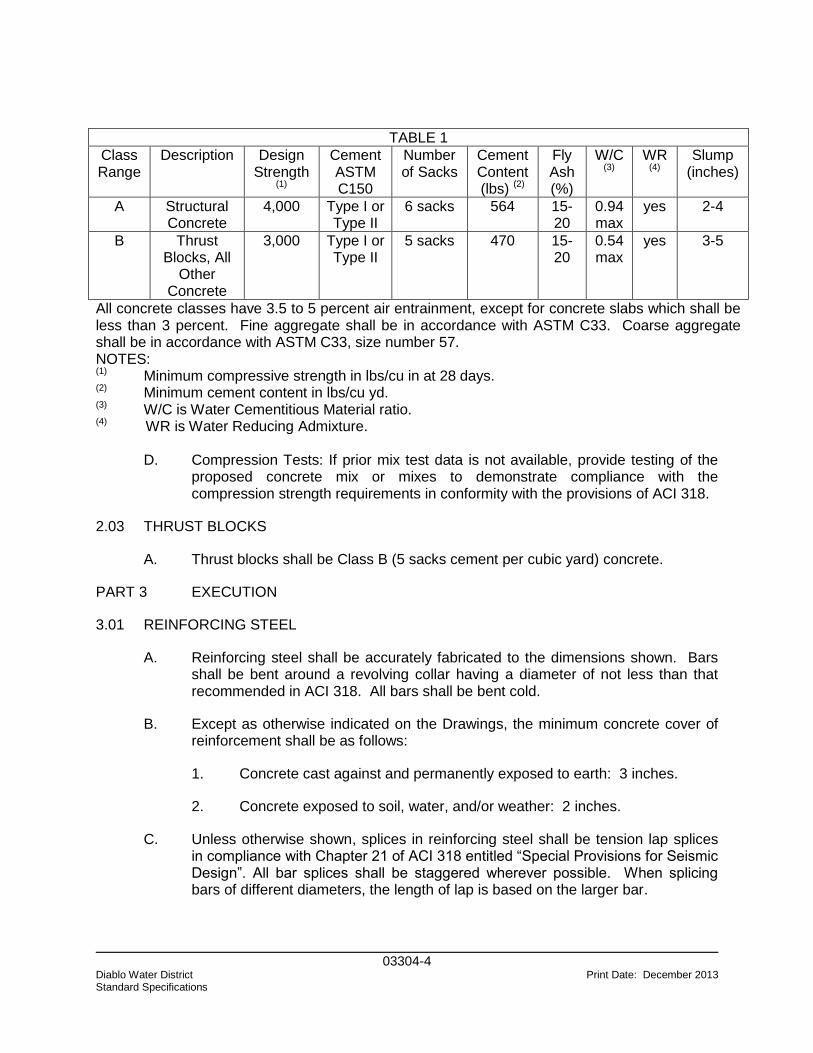
03304-4 Diablo Water District Print Date: December 2013 Standard Specifications
TABLE 1
Class Range
Description Design Strength
(1)
Cement ASTM C150
Number of Sacks
Cement Content (lbs) (2)
Fly Ash (%)
W/C (3)
WR (4)
Slump (inches)
A Structural Concrete
4,000 Type I or Type II
6 sacks 564 15-20
0.94 max
yes 2-4
B Thrust Blocks, All
Other Concrete
3,000 Type I or Type II
5 sacks 470 15-20
0.54 max
yes 3-5
All concrete classes have 3.5 to 5 percent air entrainment, except for concrete slabs which shall be less than 3 percent. Fine aggregate shall be in accordance with ASTM C33. Coarse aggregate shall be in accordance with ASTM C33, size number 57. NOTES: (1) Minimum compressive strength in lbs/cu in at 28 days. (2) Minimum cement content in lbs/cu yd. (3) W/C is Water Cementitious Material ratio. (4) WR is Water Reducing Admixture.
D. Compression Tests: If prior mix test data is not available, provide testing of the proposed concrete mix or mixes to demonstrate compliance with the compression strength requirements in conformity with the provisions of ACI 318.
2.03 THRUST BLOCKS
A. Thrust blocks shall be Class B (5 sacks cement per cubic yard) concrete.
PART 3 EXECUTION
3.01 REINFORCING STEEL
A. Reinforcing steel shall be accurately fabricated to the dimensions shown. Bars shall be bent around a revolving collar having a diameter of not less than that recommended in ACI 318. All bars shall be bent cold.
B. Except as otherwise indicated on the Drawings, the minimum concrete cover of reinforcement shall be as follows:
1. Concrete cast against and permanently exposed to earth: 3 inches.
2. Concrete exposed to soil, water, and/or weather: 2 inches.
C. Unless otherwise shown, splices in reinforcing steel shall be tension lap splices in compliance with Chapter 21 of ACI 318 entitled “Special Provisions for Seismic Design”. All bar splices shall be staggered wherever possible. When splicing bars of different diameters, the length of lap is based on the larger bar.
03304-5 Diablo Water District Print Date: December 2013 Standard Specifications
D. In no case shall any reinforcing steel be covered with concrete until the amount, condition, and position of the reinforcements have been checked by the District and permission is given to proceed with the concreting.
3.02 INSPECTION AND COORDINATION
A. The batching, mixing, transporting, placing and curing of concrete shall be subject to the inspection of the District at all times. The Contractor shall advise the District of his/her readiness to proceed at least 24 hours prior to each concrete placement. The District will inspect the preparations for concreting including the preparation of previously placed concrete, the reinforcing and the alignment, cleanliness and tightness of formwork. No placement shall be made without the inspection and acceptance of the District.
3.03 CONCRETE APPEARANCE
A. Concrete mix showing either poor cohesion or poor coating of the coarse aggregate with paste shall be remixed. If this does not correct the condition, the concrete shall be rejected.
B. Concrete for the work shall provide a homogeneous structure which, when hardened, will have the required strength, durability and appearance.
3.04 PLACING AND COMPACTING
A. No concrete shall be placed until forms, condition of subgrade and method of placement have been approved by the District. Before depositing concrete, all debris, foreign matter, dirt and water shall be removed from the forms. The contact surface between concrete previously placed and new concrete shall be cleaned and brushed with cement paste. Concrete except as indicated shall not be placed in water or submerged within 24 hours after placing, nor shall running water be permitted to flow over the surface of fresh concrete within 4 days after its placing.
B. Deposit concrete as near its final position as possible to avoid segregation due to rehandling or flowing. Pumping of concrete will be permitted when an approved design mix and aggregate sizes, suitable for pumping, are used. Do not deposit concrete which has partially hardened or has been contaminated by foreign materials.
C. High frequency mechanical vibrators shall be used to the extent necessary to obtain proper consolidation of the concrete, but not to move or transport concrete in the forms. Care shall be taken to avoid segregation of aggregates by excess vibration. Vibration shall continue until the frequency returns to normal, trapped air ceases to rise and the surface appears liquefied, flattened and glistening. Concrete adjacent to forms and around pipe stubs shall be carefully spaded or rodded.
03304-6 Diablo Water District Print Date: December 2013 Standard Specifications
3.05 THRUST BLOCKS
A. Thrust blocks shall be cast-in-place at all bends, behind each tee or each cross which is valved in such a manner that it can act as a tee, at reducers, and at the bury of fire hydrants. The thrust block shall extend from the fitting to undisturbed soil, shall be kept clear of the joints, and shall be of such bearing area as to assure adequate resistance to the force to be encountered. Thrust block poured against blind flanges or blowoffs shall be done in such a fashion as to allow access to the flange bolts.
3.06 CURING AND PROTECTION
A. Protect all concrete work against injury from the elements and defacements of any nature during construction operations.
B. Finished surfaces and slabs shall be protected from the direct rays of the sun to prevent checking and crazing.
C. Concrete placed during hot weather, shall be batched, delivered, placed, cured and protected in compliance with the recommendations of ACI 305R. The temperature of the concrete shall be such that it will cause no difficulties from loss of slump, flash set or cold joints. Immediately cover plastic concrete with sheet material during hot weather.
3.07 FIELD TESTS
A. Field control cylinder specimens will be taken by the District during the progress of the work, in compliance with ASTM C31. When the required 28 day compressive strength is not met, the District may require the removal and replacement of concrete represented by the test cylinders at no additional cost to the District.
B. Contractor shall cooperate in the making of tests by allowing free access to the work for the selection of samples, providing an insulated closed curing box for specimens, affording protection to the specimens against injury or loss through his/her operations and furnishing material and labor required for the purpose of taking concrete cylinder samples.
C. Slump tests will be made in the field by the District in conformity with ASTM C143.
D. Tests for air content shall be made in compliance with either the pressure method complying with ASTM C231 or by the volumetric method complying with ASTM C173.
E. Shrinkage
1. Field test specimens shall be handled and tested by the District as specified herein under “Concrete Mix Design - Shrinkage Tests”. A set of test cylinders shall be taken from the first batch of concrete and any initial batch thereafter in which the source of concrete ingredients has changed.
03304-7 Diablo Water District Print Date: December 2013 Standard Specifications
2. The maximum concrete shrinkage of specimens cast in the field shall not exceed the trial batch maximum shrinkage requirement by more than 25 percent.
3. If the required shrinkage limitation is not met during construction, the Contractor shall take any or all of the following actions to achieve the specified shrinkage requirements. These actions may include changing the source of aggregates, cement and/or admixtures; reducing water content; washing of aggregate to reduce fines; increasing the number of construction joints; modifying the curing requirements; or other actions designed to minimize shrinkage or the effects of shrinkage.
3.08 STRIPPING AND FINISHING CONCRETE
A. Forms shall not be stripped before the concrete has attained a strength of at least 30 percent of the ultimate design strength, except as otherwise specified.
B. Care shall be exercised to prevent damaging edges or obliterating the lines of chamfers, rustications or corners when removing the forms or doing any other work adjacent thereto.
C. All exposed concrete other than slabs shall be given a sacked finish.
Related drawings: DWD 2 DWD 3 DWD 4 DWD 9 DWD 17
END OF SECTION
03600-1 Diablo Water District Print Date: December 2013 Standard Specifications
SECTION 03600
CEMENT MORTAR AND GROUT PART 1 GENERAL
1.01 SUMMARY OF SECTION
A. Furnish all labor, materials, equipment and incidentals required and install grout complete as shown on the Drawings and as specified herein.
B. Perform all sampling and furnish all testing of materials and products by an independent testing laboratory acceptable to the Engineer but engaged by and at the expense of the Contractor.
1.02 SUBMITTALS
A. Submit to the Engineer, in accordance with Section 01300, shop drawings and product data showing materials of construction and details of installation for:
1. Commercially manufactured nonshrink cementitious grout. The submittal shall include catalog cuts, technical data, storage requirements, product life, working time after mixing, temperature considerations, conformity to required ASTM standards and Material Safety Data Sheets.
2. Commercially manufactured nonshrink epoxy grout. The submittal shall include catalog cuts, technical data, storage requirements, product life, working time after mixing, temperature considerations, conformity to required ASTM standards and Material Safety Data Sheets.
B. Samples
1. Samples of commercially manufactured grout products when requested by the Engineer.
2. Aggregates for use in concrete grout when requested by the Engineer.
C. Laboratory Test Reports
1. Submit laboratory test data as required under Section 03304 for concrete to be used as concrete grout.
1.03 REFERENCE STANDARDS
A. Referenced standards shall be the most recent version or edition.
B. American Society for Testing and Materials (ASTM)
03600-2 Diablo Water District Print Date: December 2013 Standard Specifications
1. ASTM C531 - Standard Test Method for Linear Shrinkage and Coefficient of Thermal Expansion of Chemical Resistant Mortars, Grouts and Monolithic Surfacings.
2. ASTM C827 - Standard Test Method for Change in Height at Early Ages of Cylindrical Specimens from Cementitious Mixtures.
3. ASTM C1107 - Standard Specification for Packaged Dry, Hydraulic-Cement Grout (Nonshrink).
1.04 QUALITY ASSURANCE
A. Qualifications
1. Grout manufacturer shall have a minimum of 10 years experience in the production and use of the type of grout proposed for the work.
1.05 DELIVERY, STORAGE AND HANDLING
A. Store materials in full compliance with the manufacturer's recommendations. Total storage time from date of manufacture to date of installation shall be limited to 12 months or the manufacturer's recommended storage time, whichever is less.
B. Material which becomes damp or otherwise unacceptable shall be immediately removed from the site and replaced with acceptable material.
PART 2 PRODUCTS
2.01 MATERIALS
A. Nonshrink Cementitious Grout (Nonshrink Grout)
1. Nonshrink grouts shall meet or exceed the requirements of ASTM C1107 Grades B or C and CRD-C 621. Grouts shall be portland cement based, contain a pre-proportioned blend of selected aggregates and shrinkage compensating agents and shall require only the addition of water. Nonshrink grouts shall not contain expansive cement or metallic particles. The grouts shall exhibit no shrinkage when tested in conformity with ASTM C827.
a. General purpose nonshrink grout shall conform to the standards stated above and shall be SikaGrout 212 by Sika Corp.; Set Grout by Master Builders, Inc.; Gilco Construction Grout by Gifford Hill & Co.; Euco NS by The Euclid Chemical Co.; NBEC Grout by U. S. Grout Corp. or equal.
b. Flowable (Precision) nonshrink grout shall conform to the standards stated above and shall be Masterflow 928 by Master Builders, Inc.; Hi-Flow Grout by the Euclid Chemical Co.;
03600-3 Diablo Water District Print Date: December 2013 Standard Specifications
SikaGrout 212 by Sika Corp.; Supreme Grout by Gifford Hill & Co.; Five Star Grout by U. S. Grout Corp. or equal.
B. Nonshrink Epoxy Grout
1. Nonshrink epoxy-based grout shall be a pre-proportioned, three component, 100 percent solids system consisting of epoxy resin, hardener, and blended aggregate. It shall have a compressive strength of 14,000 psi in 7 days when tested in conformity with ASTM D695 and have a maximum thermal expansion of 30 x 10-6 when tested in conformity with ASTM C531. The grout shall be Ceilcote 648 CP by Master Builders, Inc.; Five Star Epoxy Grout by U.S. Grout Corp.; Sikadur 42 Grout-Pak by Sika Corp.; High Strength Epoxy Grout by the Euclid Chemical Co. or equal.
C. Cement Grout
1. Cement grouts shall be a mixture of one part Portland cement conforming to ASTM C150, Types I, II, or III and 1 to 2 parts sand conforming to ASTM C33 with sufficient water to place the grout. The water content shall be sufficient to impart workability to the grout but not to the degree that it will allow the grout to flow.
D. Cement Mortar
1. All cement mortar shall consist of 1 part Type II Portland Cement and 1-1/2 parts fine aggregate mixed dry. Sufficient water shall be added and thoroughly mixed to produce a plastic, workable, and cohesive mixture.
PART 3 EXECUTION
3.01 PREPARATION
A. Grout shall be placed over cured concrete which has attained its full design strength unless otherwise approved by the Engineer.
B. Concrete surfaces to receive grout shall be clean and sound; free of ice, frost, dirt, grease, oil, curing compounds, laitance and paints and free of all loose material or foreign matter which may affect the bond or performance of the grout.
C. Roughen concrete surfaces by chipping, sandblasting, or other mechanical means to ensure bond of the grout to the concrete. Remove loose or broken concrete. Irregular voids or projecting coarse aggregate need not be removed if they are sound, free of laitance and firmly embedded into the parent concrete.
1. Air compressors used to clean surfaces in contact with grout shall be the oil-less type or equipped with an oil trap in the air line to prevent oil from being blown onto the surface.
03600-4 Diablo Water District Print Date: December 2013 Standard Specifications
D. Remove all loose rust, oil or other deleterious substances from metal embedments or bottom of baseplates prior to the installation of the grout.
E. Concrete surfaces shall be washed clean and then kept moist for at least 24 hours prior to the placement of cementitious or cement grout. Saturation may be achieved by covering the concrete with saturated burlap bags, use of a soaker hose, flooding the surface, or other method acceptable to the Engineer. Upon completion of the 24 hour period, visible water shall be removed from the surface prior to grouting. The use of an adhesive bonding agent in lieu of surface saturation shall only be used when approved by the Engineer for each specific location of grout installation.
F. Epoxy-based grouts do not require the saturation of the concrete substrate. Surfaces in contact with epoxy grout shall be completely dry before grouting.
3.02 INSTALLATION - GENERAL
A. Mix, apply and cure products in strict compliance with the manufacturer's recommendations and this Section.
B. Install grout in a manner which will preserve the isolation between the elements on either side of the joint where grout is placed in the vicinity of a control joint.
C. Reflect all existing underlying expansion, control and construction joints through the grout.
3.03 INSTALLATION – CEMENT GROUTS AND NONSHRINK GROUTS
A. Mix in accordance with manufacturer's recommendations. Do not add cement, sand, pea gravel or admixtures without prior approval by the Engineer.
B. Avoid mixing by hand. Mixing in a mortar mixer (with moving blades) is recommended. Pre-wet the mixer and empty any excess water. Add pre-measured amount of water for mixing, followed by the grout. Begin with the minimum amount of water recommended by the manufacturer and then add the minimum additional water required to obtain workability. Do not exceed the manufacturer's maximum recommended water content.
C. Placements greater than 3 inches in depth shall include the addition of clean, washed pea gravel to the grout mix when approved by the manufacturer. Comply with the manufacturer's recommendations for the size and amount of aggregate to be added.
D. Place grout into the designated areas in a manner which will avoid segregation or entrapment of air. Do not vibrate grout to release air or to consolidate the material. Placement should proceed in a manner which will ensure the filling of all spaces and provide full contact between the grout and adjoining surfaces. Provide grout holes as necessary.
03600-5 Diablo Water District Print Date: December 2013 Standard Specifications
E. Place grout rapidly and continuously to avoid cold joints. Do not place cement grouts in layers. Do not add additional water to the mix (retemper) after initial stiffening.
F. Begin curing immediately after form removal, cutback, and finishing. Keep grout moist and within its recommended placement temperature range for at least 24 hours after placement or longer if recommended by the manufacturer. Saturate the grout surface by use of wet burlap, soaker hoses, ponding or other approved means. Provide sunshades as necessary. If drying winds inhibit the ability of a given curing method to keep grout moist, erect wind breaks until wind is no longer a problem or curing is finished.
3.04 INSTALLATION - NONSHRINK EPOXY GROUTS
A. Mix in accordance with the procedures recommended by the manufacturer. Do not vary the ratio of components or add solvent to change the consistency of the grout mix. Do not overmix. Mix full batches only to maintain proper proportions of resin, hardener and aggregate.
B. Place grout into the designated areas in a manner which will avoid trapping air. Placement methods shall ensure the filling of all spaces and provide full contact between the grout and adjoining surfaces. Provide grout holes as necessary.
C. Minimize "shoulder" length (extension of grout horizontally beyond base plate). In no case shall the shoulder length of the grout be greater than the grout thickness.
D. Finish grout by puddling to cover all aggregate and provide a smooth finish. Break bubbles and smooth the top surface of the grout in conformity with the manufacturer's recommendations.
E. Epoxy grouts are self-curing and do not require the application of water. Maintain the formed grout within its recommended placement temperature range for at least 24 hours after placing, or longer if recommended by the manufacturer.
3.05 INSTALLATION – CONCRETE GROUT
A. Screed underlying concrete to the grade shown on the Drawings. Provide the surface with a broomed finish, aligned to drain. Protect and keep the surface clean until placement of concrete grout.
B. Remove the debris and clean the surface by sweeping and vacuuming of all dirt and other foreign materials. Wash the tank slab using a strong jet of water. Flushing of debris into tank drain lines will not be permitted.
C. Saturate the concrete surface for at least 24 hours prior to placement of the concrete grout. Saturation may be maintained by ponding, by the use of soaker hoses, or by other methods acceptable to the District. Remove excess water just prior to placement of the concrete grout. Place cement slurry immediately ahead of the concrete grout so that the slurry is moist when the grout is placed. Work
03600-6 Diablo Water District Print Date: December 2013 Standard Specifications
the slurry over the surface with a broom until it is coated with approximately 1/16 to 1/8 inch thick cement past. (A bonding grout composed of 1 part Portland cement, 1-1/2 parts fine sand, an approved bonding admixture and water, mixed to achieve the consistency of thick paint, may be substituted for the cement slurry.)
D. Place concrete grout to final grade using the scraper mechanism as a guide for surface elevation and to ensure high and low spots are eliminated. Unless specifically approved by the equipment manufacturer, mechanical scraper mechanisms shall not be used as a finishing machine or screed.
Related drawings: DWD 9
END OF SECTION
15100-1 Diablo Water District Print Date: December 2013 Standard Specifications
SECTION 15100
VALVES, HYDRANTS AND APPURTENANCES PART 1 GENERAL
1.01 SUMMARY OF SECTION
A. Furnish all labor, supervision, materials, equipment and incidentals required and install complete and ready for operation all valves as shown on the Drawings and as specified herein.
B. Specifications for the following valves and appurtenances are included in this section.
1. Valve Actuators
2. Gate Valves
3. Butterfly Valves
4. Ball Valves
5. Insulating Fittings
6. Fire Hydrants
7. Air Release Valves
8. Blowoffs
9. Piping Specialties
a. Dielectric Connectors
b. Plugs and Caps
c. Miscellaneous Adaptors
d. Flexible Connectors
i. Flanged Coupling Adapters
ii. Mechanical Couplings
e. Harnessing and Restraints
f. Appurtenances and Miscellaneous Items
g. Valve Boxes

15100-2 Diablo Water District Print Date: December 2013 Standard Specifications
h. Tapping Tees, Saddles, and Sleeves
1.02 SUBMITTALS
A. Submittals shall include the following:
1. The manufacturer or supplier.
2. Drawings showing all important details of construction and dimensions.
3. Descriptive literature, bulletins and/or catalogs of the equipment.
4. The total weight of each item.
5. A complete bill of materials.
6. Additional submittal data, where noted with individual pieces of equipment.
B. Test Reports
1. Provide hydrostatic test data, per manufacturer’s standard procedure or MSS-SP-61 for all valve types.
C. Certificates
1. Submit an affidavit of compliance with the specified standards, including certified results of required tests and certification of proper installation.
1.03 REFERENCE STANDARDS
A. Referenced standards shall be the most recent version or edition.
B. American Society for Testing and Materials (ASTM)
1. ASTM A126 - Specification for Gray Iron Castings for Valves, Flanges and Pipe Fittings.
2. ASTM A276 - Standard Specification for Stainless and Heat-Resisting Steel Bars and Shapes.
C. American Water Works Association (AWWA)
1. ANSI/AWWA C111/A21.11 – Rubber-Gasket Joint for Ductile-Iron Pressure Pipe and Fittings
2. AWWA C502 - Dry-Barrel Fire Hydrants
3. ANSI/AWWA C504 - Standard for Rubber-Seated Butterfly Valves
4. AWWA C540 - Power-Actuating Devices for Valves and Sluice Gates
15100-3 Diablo Water District Print Date: December 2013 Standard Specifications
5. AWWA C550 - Standard for Protective Epoxy Interior Coatings for Valves
6. and Hydrants
7. AWWA C800 - Underground Service Line Valves and Fittings
D. American National Standards Institute (ANSI)
1. ANSI B2.1 - Specifications, Dimensions, Gauging for Taper and Straight Pipe Threads (except dry seals).
2. ANSI/ASME B 16.1 - Cast Iron Pipe Flange and Flanged Fittings Class 25, 125, 250 and 800
3. ANSI/ASME B 16.10 - Face-to-Face and End-to-End Dimensions of Valves
E. American Iron and Steel Institute (AISI)
F. Manufacturer's Standardization Society of the Valve and Fittings Industry (MSS)
1. MSS-SP-61 - Pressure Testing of Steel Valves.
G. National Electrical Manufacturers Association (NEMA)
H. Underwriters Laboratories (UL)
I. Factory Mutual Insurance (FM)
1.04 QUALITY ASSURANCE
A. Qualifications
1. Valves and appurtenances shall be products of well established firms who are fully experienced, minimum 10 years, reputable and qualified in the manufacture of the particular equipment to be furnished.
2. The equipment shall be designed, constructed and installed in accordance with the best practices and methods and shall comply with these Specifications as applicable.
3. All units of the same type shall be the product of one manufacturer.
B. Certifications
1. The manufacturers shall furnish an affidavit of compliance with Standards referred to herein as specified in paragraph 1.03C. Refer to Part 4 for testing required for certain items in addition to that required by referenced standards.
15100-4 Diablo Water District Print Date: December 2013 Standard Specifications
C. Inspection of the units may also be made by the District or other representative of the District after delivery. The equipment shall be subject to rejection at any time due to failure to meet any of the Specification requirements, even though submittal data may have been accepted previously. Equipment rejected after delivery shall be marked for identification and shall be removed from the job site at once.
1.05 DELIVERY, STORAGE AND HANDLING
A. Packing and Shipping
1. Care shall be taken in loading, transporting and unloading to prevent injury to the valves, appurtenances, or coatings. Equipment shall not be dropped. All valves and appurtenances shall be examined before installation and no piece shall be installed which is found to be defective. Any damage to the coatings shall be repaired as acceptable to the Construction Manager.
2. Prior to shipping, the ends of all valves shall be acceptably covered to prevent entry of foreign material. Covers shall remain in place until after installation of connecting piping is completed.
a. All valves 3 inch and larger shall be shipped and stored on site until time of use with plastic, wood, or plywood covers on each valve end.
b. Valves smaller than 3 inch shall be shipped and stored as above except that heavy plastic or cardboard covers may be used on the openings.
c. Rising stems and exposed stem valves shall be coated with a protective oil film which shall be maintained until the valve is installed and put into use.
d. Any corrosion in evidence at the time of acceptance by the District shall be removed, or the valve shall be removed and replaced.
3. Insofar as is practical, the equipment specified herein, shall be factory assembled. The parts and assemblies that are shipped unassembled, shall be packaged and tagged in a manner that will protect the equipment from damage and facilitate the final assembly in the field.
B. Weight, handling instructions, type of storage required, and instructions for protective maintenance during storage shall be included with each shipment to the project site.
1.06 MAINTENANCE
A. Special tools and the manufacturer's standard spare parts, if required for normal operation and maintenance, shall be supplied with the equipment.
15100-5 Diablo Water District Print Date: December 2013 Standard Specifications
B. Provide all special tools required for normal maintenance. Tools shall be packaged in a steel case, clearly and indelibly marked on the exterior to indicate equipment for which tools are intended.
C. Provide to the District a list of all spare and replacement parts with location where they are available.
PART 2 PRODUCTS
2.01 MATERIALS AND EQUIPMENT - GENERAL
A. Valves and appurtenances shall be of the size shown on the Drawings or as noted and as far as possible equipment of the same type shall be identical and from one manufacturer.
B. Valves and appurtenances shall have the name of the maker, nominal size, flow directional arrows, working pressure for which they are designed and standard referenced, cast in raised letters or indelibly marked upon some appropriate part of the body.
C. Unless otherwise noted, items shall have a minimum working pressure of 150 psi or be of the same working pressure as the pipe they connect, whichever is higher and suitable for the pressures noted where they are installed.
D. Joints, size and material - unless otherwise noted or required by the District:
1. Except where noted, all joints referred to herein shall be of the same type, nominal diameter, material and with a minimum rating equal to the pipe or fittings they are connected to.
2. Valves and appurtenances shall be of the same nominal diameter as the pipe or fittings they are connected to.
E. Provide all special adapters as required to ensure compatibility between valves, appurtenances and adjacent pipe.
F. Valves and actuators shall be designed for submerged service where water may completely submerge the valve and operator. All other units shall be as a minimum weather tight.
G. Valve nut extensions shall be Schedule 80 steel. The length (in inches) of the extension shall be arc welded on the top of the circular plate.
H. Valves shall be wrapped in polyethylene. Non stainless steel bolts and nuts shall be coated with bitumastic.
2.02 VALVE ACTUATORS
A. Unless otherwise noted, valves shall be manually actuated. The lever type operators may be supplied on quarter-turn type valves, 2 inches and smaller, if
15100-6 Diablo Water District Print Date: December 2013 Standard Specifications
recommended by the valve manufacturer. Buried valves and those with operating nuts shall have a non-rising stem with an AWWA 2 inch nut.
B. All actuators shall be capable of moving the valve from the full open to full close position and in reverse and holding the valve at any position part way between full open or closed.
C. Each operating device shall have cast on it the word "OPEN" and an arrow indicating the direction of operation.
D. Gear Actuators
1. Unless otherwise noted, gear actuators shall be provided for the following: all valves of larger than 8 inch nominal diameter; all buried valves with operating shaft mounted horizontally (butterfly, plug, etc.); where specified and/or indicated on the Drawings; where manual operator effort is greater than 80 ft-lbs rim pull.
2. Gear actuators shall be of the traveling nut type with output shaft perpendicular to valve shaft, having a removable hand wheel mounted on the output shaft. Unless noted, they shall conform to AWWA C504, except with butterfly valves which need not be certified.
3. Actuators shall be capable of being removed from the valve without dismantling the valve or removing the valve from the line.
4. Gearing shall be machine-cut steel designed for smooth operation. Bearings shall be enclosed and permanently lubricated, with bronze bearing bushings provided to take all thrusts and seals and to contain lubricants. Housings shall be sealed to exclude moisture and dirt, allow the reduction mechanisms to operate in lubricant and be of the same material as the valve body.
5. Manual operator input effort to the handwheel shall be a maximum of 40 ft-lbs for operating the valve from full open to full close, under any conditions. Gear actuators shall indicate valve position and have adjustable stops. Maximum handwheel size shall be 24 inch diameter.
E. All position indication and direction of opening arrows shall be embossed, stamped, engraved, etched or raised decals.
F. Unless otherwise noted, all valves larger than 3 inch nominal diameter shall be provided with position indicators at the point of operation.
2.03 GATE VALVES
A. Gate valves shall be used for pipe diameters 12 inches or smaller.
B. Gate valves 4 inches through 12 inches shall conform to AWWA C509, and shall be resilient seated with fully encapsulated disk with nonrising stem, and have O
15100-7 Diablo Water District Print Date: December 2013 Standard Specifications
ring stuffing boxes. Stuffing boxes shall be bolted and constructed so as to aid valve repair. Valves shall open counterclockwise and be fitted with 2 inch square operating nuts.
C. Valve ends shall be flanged, push-on, or mechanical joint, as required by the adjoining pipe material. Gate valves installed on PVC plastic pipelines shall have push-on or flange by push-on ends. Valves with mechanical joint ends shall not be used with PVC plastic pipe except by special permission of the District.
D. All gate valves 4 inches through 12 inches in size shall be Mueller with 304 stainless steel valve bonnet, stuffing box, nuts, and bolts.
2.04 BUTTERFLY VALVES
A. General: Butterfly valves up to 72 inches shall conform to ANSI/AWWA C504 subject to the following requirements. Valves shall be of the size shown. Flanged valves shall be a 150-pound class type valve drilled with a 125-pound bolt pattern and shall be short-bodied. Shaft seals shall be designed for use with standard split-V type packing, or other acceptable seal. The interior passage of butterfly valves shall not have any obstructions or stops. The rubber seat shall be EPDM and shall be positively clamped or bonded into the disc or body of the valve. Cartridge-type seats will not be allowed. All interior ferrous surfaces of valves shall be factory-applied epoxy lined in conformance with AWWA C550. Epoxy interior lining and disc of each valve shall be certified to be holiday free from the factory, with valve serial numbers indicated. Exterior of valves shall be epoxy coated, exclusive of the flange faces; holiday free certification is not required.
B. Permanently self-lubricating body bushings shall be provided and shall be sized to withstand bearing loads. Stuffing box of liberal dimensions shall be provided at the operator end of the vane shaft. Packing shall be of the self-compensating type. A sealing element utilizing O-rings shall also be acceptable. Packing shall be held in place by a bolted corrosion resistant retainer plate or gland; retainer clips are not acceptable. Replacement of seals, for all size butterfly valves, shall not require removal of the valve from the line.
C. The valve shaft shall be designed for both torsional and shearing stresses when the valve is operated under its greatest dynamic or seating torque. The extended operating nut shall be secured with a shear pin designed to shear at 300 foot-pounds of torque. No reductions of shaft diameter will be allowed except at the operator connection. Any reduction shall have a full radius fillet.
D. Valves shall be flanged for in-line applications and flange by mechanical joint for tee or cross applications.
E. Manual Operators: Operators shall conform to ANSI/AWWA C504, subject to the
F. following requirements. Unless otherwise shown, all unburied manually-operated butterfly valves shall be equipped with a handwheel and position indicator. Buried valves shall be equipped with a 2-inch square operating nut with a nut actuator. All operators shall be side mounted.
15100-8 Diablo Water District Print Date: December 2013 Standard Specifications
G. Body Stops: The use of a stop or lug cast integrally with or mechanically secured to the body for the purpose of limiting disc travel by means of direct contact or interference with the valve disc (in either the open or closed position) will not be acceptable.
H. Flanges shall be finished to true plane surfaces within a tolerance limit of 0.005 inches. The finished face shall be normal to the longitudinal valve axis within a maximum angular variation tolerance of 0.002 inch per foot of flange diameter.
I. Coatings and Linings: All butterfly valve coatings and linings shall be
J. Factory applied and holiday free. Manufacturer shall provide a Certificate of Compliance to this effect.
K. Where mechanical joint ends are specified, either mechanical joint or push-on ends conforming to ANSI/AWWA C111/A21.11 will be acceptable.
L. Manufacturers: Mueller Lineseal III Class 150B, no equal, certified with serial number.
2.05 BALL VALVES
A. Ball valves shall be three-piece, for use on potable water piping. Maximum operating pressure shall be 150 psig. Actuator shall be manual, lever type.
B. Materials shall be as follows:
1. Body: Lead Free Brass, ASTM B30-12.
2. Ball: Hard chrome plated brass ball.
3. Stem: Lead Free Brass, ASTM B30-12.
4. Seats: Durafill.
5. Seals: TFE.
6. Bolting: Type 316 stainless steel.
C. Shall be as manufactured by Watts Series B-6000; Or equal.
2.06 INSULATING FITTINGS
A. Fittings shall be of type to provide control of electrolysis and equal to "Dielectric" as manufactured by Watts Regulator Co., or equal.
2.07 FIRE HYDRANTS
A. Fire hydrants shall be wet-barrel type, and shall be Clow 960 (with 1x4½” & 2x2½” connections) or as approved by the Contra Costa County Fire Protection District. The Contra Costa County Fire Protection District shall have final
15100-9 Diablo Water District Print Date: December 2013 Standard Specifications
authority in specifying fire hydrant manufacturer, model, outlet configuration, and color.
B. All fire hydrants shall be mounted to a Clow LB 400 check valve with break-off spool. The hydrant body shall be mounted to this spool with stainless steel bolts, sized as required.
C. Ductile iron hydrant bury shall be by Sigma or South Bay.
D. All fire hydrants shall be painted with two coats of Pollard yellow #P68205 paint.
2.08 AIR RELEASE VALVES
A. Air release valves shall have 1 inch inlet connections. Working parts shall be brass, stainless steel, or other non corroding material. Valve body and working parts shall be designed for a working pressure of 150 psi. The orifice shall be sized for a working pressure of 80 psi. Floats shall be stainless steel.
B. Air release valves shall be Crispin Universal UL10. Air release valve enclosures shall be Christy B36 with extension. Enclosure lid shall be Placer Waterworks catalog #PW/AE3618-M, with 1”x4” stainless steel name plate engraved with “Diablo Water District Potable Water”. Angle valve for ARV – Mueller B-24258. Screens for ARVs shall be Christy 1” FPT #10 or DWD approved equal.
2.09 BLOWOFFS
A. A 2 inch blowoff assembly shall be installed at the termination of each water main 12 inches and smaller in size, except that a hydrant shall be installed where possible. The blowoff outlet shall be installed at the invert of the end cap.
B. A 4 inch blowoff assembly shall be installed at the termination of each water main 16 inches and larger in size, except that a hydrant shall be installed where possible. The blowoff outlet shall be installed at the invert of the end cap where possible.
C. Blowoff piping and valves shall not rest on the trench walls, bottom, or blocking prior to pouring thrust blocks.
D. Valves for blowoffs shall be Mueller B-24286.
15100-10 Diablo Water District Print Date: December 2013 Standard Specifications
2.10 PIPING SPECIALTIES
A. Dielectric Connectors
1. Dielectric pipe fittings/insulators and unions shall be used to prevent galvanic action wherever valves or piping of dissimilar metals connect. This shall be particularly the case for copper, brass and bronze piping connecting to cast iron or steel piping systems.
2. Dielectric unions shall be used for 2 inch and smaller connections. Steel union nuts shall meet ASTM A575 requirements. The steel or ductile iron connection end shall have a steel body and shall have accurately machined taper tapped pipe threads in accordance with ANSI B2.1. The copper connection end shall be a copper solder joint that meets requirements of ASTM B88. Dielectric unions shall be rated for at least 250 psi at 210 degrees F.
3. Dielectric flange unions shall be used for connections 2-1/2 inches and larger. Cast iron flanges shall meet ASTM A126; the copper solder end shall meet ASTM B62 and the pipe thread shall meet ANSI B2.1. Dielectric flange unions shall be rated for at least 175 psi at 210 degrees F.
4. Dielectric unions and flange unions shall be as manufactured by Epco Inc., Cleveland, OH or equal.
5. Flange insulating kits shall be as acceptable to the Engineer, as manufactured by PSI or equal.
6. Insulated sleeve couplings and flange adaptors shall be similar to those units as specified elsewhere.
B. Plugs and Caps
1. Provide standard plug or cap as required for testing; plugs and caps shall be suitable for permanent service.
2. Plug or cap or otherwise cover all piping work in progress.
C. Miscellaneous Adapters
1. Between different types of pipe and/or fittings special adapters may be required to provide proper connection. Some of these may be indicated on the Drawings or specified with individual types of pipe or equipment. However, it is the Contractor's responsibility to ensure proper connection between various types of pipe, to structures and between pipe and valves, gates, fittings and other appurtenances. The Contractor shall provide all adapters as required, whether specifically noted or not.
15100-11 Diablo Water District Print Date: December 2013 Standard Specifications
2. As required, these adapters shall be suitable for direct bury, with proper dielectric insulation and as a minimum, if metallic (not stainless steel or galvanized), with two coats of Coal Tar Epoxy.
D. Flexible Connectors
1. Flanged Coupling Adapters for plain end pipe at fittings, valves and equipment shall be Dresser Style 127 or 128, similar models by ITT; Baker or equal. Nuts, bolts and other hardware shall be Type 304 stainless steel.
2. Mechanical Couplings shall be rated for a minimum working pressure of 150 psi. The barrel shall be a minimum 10 inches long. Couplings shall be cleaned and shop primed with manufacturer’s standard rust inhibitive primer. Mechanical couplings shall be Smith-Blair, Romac, JCM, or Apac only, with stainless steel nuts, bolts, and threaded rods.
E. Harnessing and Restraints
1. Where harnessed couplings or adapters are noted, they shall conform to AWWA Manual M11 except as modified by the Drawings or this Specification.
2. Unless otherwise noted, size and material for tie rods, clamps, plates and hex nuts shall be as shown on the Drawings, or, if not shown on the Drawings, shall be as required in AWWA Manual M11. Manufactured restraining clamp assemblies shall be as manufactured by Stellar Corporation, Columbus, OH or fabricated equal.
3. Restrained joints (such as welded, locking mechanical joints) shall be of the type specified with the individual type of pipe. If not specified, restrained (locking) mechanical joint pipe shall be of the manufacturers standard design utilizing a locking device (ring or ears) integrally cast with the pipe.
4. For up through 18-in diameter ductile iron pipe only, the following may be used as an alternative to other restraint system:
a. The optional mechanical joint restrains shall be incorporated in the design of a follower gland. The gland shall be manufactured of ductile iron conforming to ASTM A536. Dimensions of the gland shall be such that it can be used with the standardized mechanical joint bell and tee-head bolts as specified with the pipe.
b. The restraint mechanism shall consist of numerous individually activated gripping surfaces to maximize restraint capability. The gripping surfaces shall be wedges designed to spread the bearing surfaces on the pipe. Twist-off nuts, sized same as tee-head bolts, shall be used to ensure proper actuating of restraining devices. When the nut is sheared off, standard hex nut shall remain.
15100-12 Diablo Water District Print Date: December 2013 Standard Specifications
c. The mechanical joint restraint device for ductile iron pipe shall have a working pressure of at least 250 psi with a minimum safety factor of 2:1.
d. The mechanical joint restraint devices shall be of the type listed below or equal.
e. For Ductile Iron Pipe: EBAA Iron, Inc. Megalug 1100 series.
F. Appurtenances and Miscellaneous Items
1. All gaskets, glands, bolts, nuts and other required hardware shall be provided for connection of piping and appurtenances. Bolts and nuts shall be high strength, 304 stainless steel, with hexagon nut (unless otherwise noted). T-bolts shall be used on mechanical joint fittings. All other hardware shall be of the size, type and number as required and recommended by the piping or appurtenance manufacturer and as specified herein. T-bolts shall be as supplied by the manufacturer.
2. All gaskets for flanges shall be full face and suitable for 200 degrees F operating temperature, and the fluids carried. Gaskets shall be Garlock Multi-Swell 3760-U, only. Gaskets containing asbestos shall not be permitted. Bolt-ups for flanges shall be 304 stainless steel.
3. Plugs, caps and similar accessories shall be of the same material as the pipe and of the locking type, unless otherwise noted.
4. Unions shall be of the same material as the pipe, except for dielectric connections.
5. Special protective tape shall be 10 mil tape.
G. Valve Boxes
1. Valve boxes shall be of suitable rolled steel or concrete construction and not less than 8 inches in diameter. Suitable cast iron traffic frames and covers shall be provided. Covers shall have cast thereon the words “WATER”, or as appropriate for the installation. All parts of the traffic frames and covers shall be coated by dipping in bituminous varnish or coal tar. Rolled steel valve boxes shall be completely coated with coal tar enamel before installation. Valve boxes shall be Christy G5 or G12 as required.
H. Tapping Tees, Saddles, and Sleeves
1. Tapping sleeves up to 18” shall be JCM 432. Tapping sleeves over 18” shall be per DWD. All hardware for tapping tees shall be Type 304 stainless steel. In size on size installations, undersize the diameter of the tap by ½-inch. Flanges on stainless steel tees shall be stainless steel. A ¾-inch NPT test plug shall be provided.
15100-13 Diablo Water District Print Date: December 2013 Standard Specifications
PART 3 INSTALLATION
3.01 INSTALLATION - GENERAL
A. All valves and appurtenances shall be installed per these Specifications, the manufacturer's instructions and approved shop drawings in the locations shown, true to alignment and rigidly supported. Any damage to the above items shall be repaired to the satisfaction of the District before they are installed.
B. All materials shall be carefully inspected for defects in construction and materials. All debris and foreign material shall be cleaned out of openings, etc. All valve flange covers shall remain in place until connected piping is in place. All operating mechanisms shall be operated to check their proper functioning and all nuts and bolts checked for tightness. Valves and other equipment which do not operate easily, or are otherwise defective, shall be repaired or replaced.
C. Unless otherwise noted, joints for valves and appurtenances shall be made up utilizing the same procedures as specified under the applicable type connecting pipe joint and all valves and other items shall be installed in the proper position as recommended by the manufacturer. Contractor shall be responsible for verifying manufacturers' torquing requirements for all valves.
3.02 INSTALLATION OF MANUAL OPERATIONAL DEVICES
A. Unless otherwise noted, all operational devices shall be installed with the units of the factory, as shown on the Drawings or as acceptable to the District to allow accessibility to operate and maintain the item and to prevent interference with other piping, valves and appurtenances.
B. Valves shall be set plumb, supported against settlement and properly fitted to the adjacent sections of main. All valves shall be operated prior to installation in accordance with the manufacturer’s recommendations. Valve interior shall be clean and wet prior to operation.
C. For manually operated valves 3-inch in diameter and smaller, valve operators and indicators shall be rotated to display toward normal operation locations.
D. Floor boxes, valve boxes, extension stems and low floor stands shall be installed vertically centered over the operating nut, with couplings as required and the elevation of the box top shall be adjusted to conform with the elevation of the finished floor surface or grade at the completion of the Contract. Boxes and stem guides shall be adequately supported during concrete pouring to maintain vertical alignment. Valves boxes must not bear on the valve or pipe so that surface traffic loads are not transferred onto pipe.
E. All hydrants shall stand plumb. Hydrants with pumper nozzles shall have hose nozzles parallel with, and the pumper nozzle perpendicular to, the curb line. Hydrants having hose nozzles 90 degrees apart shall be set so that the line bisecting the angle between the nozzles is perpendicular to the curb line. All
15100-14 Diablo Water District Print Date: December 2013 Standard Specifications
hydrants shall be installed with an LB 400 check valve with breakoff spool per manufacturer’s recommendations.
F. Immediately before installation of a hydrant, the following operations shall be performed: (a) the hydrant shall be thoroughly inspected; (b) the hydrant interior shall be thoroughly cleaned; (c) the hydrant shall be opened and closed as many times as may be necessary to determine if all parts are in working order, with valves seating properly; and (d) the packing gland checked to determine if the packing is in place and the gland nut properly tightened.
G. Air release valves shall be installed to not create a cross connection.
H. Installation of Pipeline Appurtenances
1. All pipeline appurtenances shall be installed as required and in accordance with the manufacturer's recommendations, as acceptable to the Engineer.
2. Gages, meters and similar in-line items shall be isolated from testing pressures in excess of the rated pressure of the assembly.
3. Use Teflon tape on all screwed fittings.
I. Installation of Tapping Tees
1. After installation, poly bag tapping tees.
3.03 CLEANING
A. All items including valve interiors shall be cleaned prior to installation, testing, disinfection, and final acceptance. Disinfection shall be as specified in 02675.
PART 4 INSPECTION AND TESTING
4.01 INSPECTION, TESTING AND CORRECTION OF DEFICIENCIES
A. Take care not to over pressure valves or appurtenances during pipe testing. If any unit proves to be defective, it shall be replaced or repaired to the satisfaction of the District.
B. Tapping tees shall be tested with air at 90 psi for 60 minutes.
Related drawings: DWD 8 DWD 19 DWD 9 DWD 21 DWD 15 DWD 22
DWD 16 DWD 17 DWD 18 END OF SECTION
15400-1 Diablo Water District Print Date: December 2013 Standard Specifications
SECTION 15400
SERVICES AND METER INSTALLATIONS
PART 1 GENERAL
1.01 SCOPE OF WORK
A. This Section specifies the basic piping and service meter materials of each service, including valves. Specific uses and applications are specified in other related Sections.
B. Furnish all labor, materials, equipment, services and incidentals required and install as shown on the Drawings and as specified herein.
1. Service Piping
2. Meters
3. Meter Boxes
4. Corporation Stops
5. Double Check Valve
6. Reduced Pressure Backflow Preventer
7. Double Check Detector Valves
8. Fire Protection
1.02 SUBMITTALS
A. Submit, in accordance with this Section, shop drawings and technical literature covering details of all service-meter systems being furnished under this Section prior to fabrication, assembly or shipment.
B. For units that will be shipped exposed, provide a description of the protective packaging that will be used during transit
C. All submittals shall contain a statement that Sections 15400 and 15100 have been read and complied with. The certification statement shall be made by all of the following that are applicable; the Contractor, sub-contractor and the vendor. The statement shall be an individual statement for each party involved, and shall be included with every submittal and resubmittal.
15400-2 Diablo Water District Print Date: December 2013 Standard Specifications
1.03 REFERENCE STANDARDS
A. Referenced standards shall be the most current edition.
B. American Society for Testing and Materials
1. ASTM B88 – Standard for Seamless Copper Water Tube
1.04 QUALITY ASSURANCE
A. Inspection by the District’s representative or failure to inspect shall not relieve the Contractor of responsibility to provide materials and perform the work in accordance with the documents.
B. The piping manufacturer shall furnish an affidavit of compliance certifying that all materials used and work performed shall comply with the specified requirements. The Contractor shall provide copies of mill test confirming the type of material used in the various components.
1.05 COORDINATION
A. The Contractor shall assume full responsibility for coordination of the water service systems, including; scheduling, and verification that all structures, piping and the mounting of equipment are compatible.
PART 2 PRODUCTS
2.01 SERVICE PIPING
A. Service lines sizes up to 1 inch shall be Type K annealed (soft) copper tubing, polyethylene coated Mueller Streamline and shall conform to ASTM B88. Service lines above 1 inch shall be as approved by the District. Polyethylene piping shall be used in soil with a corrosion rating of 1 or 2 as required by the District. Service lines above 1 inch shall be Type K annealed (soft) copper tubing in blue poly-wrap..
B. All copper piping 2-1/2 inches and larger and all buried copper piping shall be Type S-2 brazed. Brazing filler metal classified as BCu4 or BCu5, with minimum melting point of 1300 degrees F. Use wrought fittings for brazing.
C. Double strap service saddles (clamps) shall be used on all service connections as shown on the standard drawings. However, wide band saddles may be used on PVC plastic pipe. Services saddles shall be bronze when used with PVC pipe, and full circle stainless steel with full circle insulating pad, when used with ductile iron or steel pipe. Outlet thread shall be AWWA Standard (cc) thread only. Service saddles shall be Mueller.
15400-3 Diablo Water District Print Date: December 2013 Standard Specifications
2.02 METERS
A. Flow meters in sizes 5/8” through 1” shall be Sensus iPerl Water Meter (cubic feet). 5/8” meters shall be embossed with 5/8” on the meter body, with 520M FlexNet MTX Unit.
B. Flow meters in sizes 1-1/2” through 2” shall be compound meters of model: Sensus SRH TRPL Compound Meter (cubic feet) with 520M FlexNet MTX Unit (single port per meter).
C. Flow meters in sizes 3” through 4” shall be compound meters of model: Sensus Omni C2 or T2 Meter (cubic feet) with 520M FlexNet MTX Unit (single port per meter).
2.03 METER BOXES
A. Meter boxes, extensions, and covers shall be commercial products. Boxes shall be large enough to allow easy maintenance, testing, and removal or backflow preventers, meters, and valves. Traffic covers may be required as described below under Installation.
1. Meter boxes for 5/8” through 2” meter installations shall be Christy B-12, B-16, or B-30 depending on the service size and as indicated on the standard drawings. Meter boxes for meters less than 1-1/2 inch in size shall have Christy B12P001-F (Flex Net) lids. Lids must have drilled hole for FlexNet 520M Unit.
2. Meter boxes for 3-inch meter installations shall be Christy B-40 with B40-61D galvanized lid.
3. Meter boxes for 4-inch installations shall be Christy B-44 with B44-62D lid.
B. All angle meter stops shall be designed to allow padlocking in the “off” position. One and 1-1/2 inch and 2 inch angle stops shall be Mueller. Angle meter stops for 5/8 inch meters shall be 1 inch with a 1 inch by 3/4 inch reducing meter bushing. 1 inch angle meter stops shall be Mueller B-24258. 1-1/2 inch through 2 inch angle meter stops shall be Mueller B-24276.
2.04 CORPORATION STOPS
A. All 1-1/2 inch and 2-inch corporation stops shall be of ball valve design. Corporation stops shall be of bronze or brass and shall be designed and manufactured in accordance with AWWA C800. Corporation stops shall be Mueller B-25008 with CC thread only.
15400-4 Diablo Water District Print Date: December 2013 Standard Specifications
2.05 BACKFLOW PREVENTION DEVICES
A. In accordance with its Regulation No. 6, the District shall determine for each service whether a backflow prevention device is required.
B. Double Check Valve
1. Shall be required at all houses with fire sprinkler systems, and in other locations as required by the District.
2. Double check valves for sizes ¾-inch through 2 inches shall be Febco 850U.
3. Houses with fire sprinkler systems shall use a 1-inch flow meter with a 1-1/4 inch double check valve.
4. Installations shall be made adjacent to the meter in a separate utility box.
5. ¼ inch MIP X ¼ inch flare adapter to be installed by the Contractor.
C. Reduced Pressure Backflow Preventer
1. Shall be required on all irrigation systems, and in other locations as required by the District.
2. Reduced pressure backflow preventers for sizes ¾-inch through 2-inches shall be Febco 825YA RP with ball valves. For 5/8-inch lines, use ¾-inch reduced pressure backflow preventer. Unit shall be installed with brass fittings and without a setter. Install BPDI Guardshack two-piece protective enclosure around unit, hinged, stainless steel with forest green powder coating, or approved equal.
3. Reduced pressure backflow preventers for sizes 2½-inch through 10-inches shall be Febco 880V N-shape. Unit shall be installed with a setter. Install fence enclosure around unit. Install 4-inch guard posts around perimeter of unit if near traffic areas.
D. Double Check Detector Valve
1. Shall be required on all fire protection systems, and in other locations as required by the District.
2. Double check detector valve assembly for sizes 3-inch through 10-inches shall be Febco 876V N-shape. Unit shall be installed with a setter. Install fence enclosure around unit. Install 4-inch guard posts around perimeter of unit if near traffic areas.
3. To be supplied with Sensus iPerl and FlexNet unit.
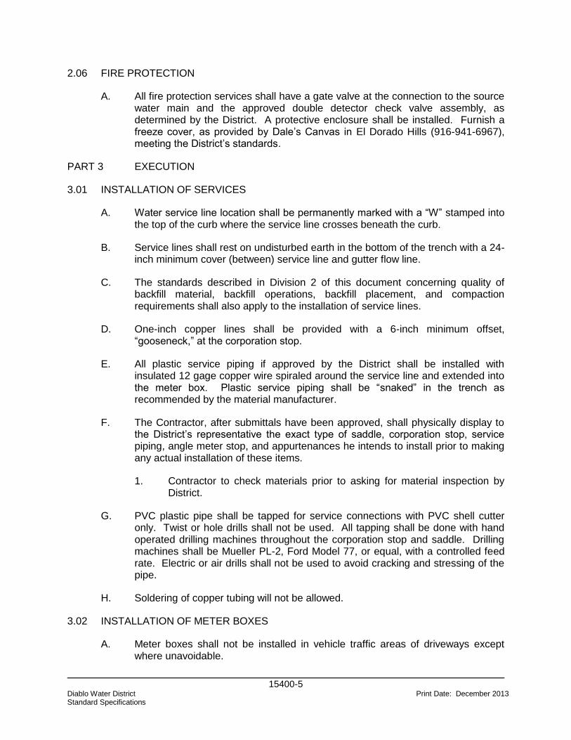
15400-5 Diablo Water District Print Date: December 2013 Standard Specifications
2.06 FIRE PROTECTION
A. All fire protection services shall have a gate valve at the connection to the source water main and the approved double detector check valve assembly, as determined by the District. A protective enclosure shall be installed. Furnish a freeze cover, as provided by Dale’s Canvas in El Dorado Hills (916-941-6967), meeting the District’s standards.
PART 3 EXECUTION
3.01 INSTALLATION OF SERVICES
A. Water service line location shall be permanently marked with a “W” stamped into the top of the curb where the service line crosses beneath the curb.
B. Service lines shall rest on undisturbed earth in the bottom of the trench with a 24-inch minimum cover (between) service line and gutter flow line.
C. The standards described in Division 2 of this document concerning quality of backfill material, backfill operations, backfill placement, and compaction requirements shall also apply to the installation of service lines.
D. One-inch copper lines shall be provided with a 6-inch minimum offset, “gooseneck,” at the corporation stop.
E. All plastic service piping if approved by the District shall be installed with insulated 12 gage copper wire spiraled around the service line and extended into the meter box. Plastic service piping shall be “snaked” in the trench as recommended by the material manufacturer.
F. The Contractor, after submittals have been approved, shall physically display to the District’s representative the exact type of saddle, corporation stop, service piping, angle meter stop, and appurtenances he intends to install prior to making any actual installation of these items.
1. Contractor to check materials prior to asking for material inspection by District.
G. PVC plastic pipe shall be tapped for service connections with PVC shell cutter only. Twist or hole drills shall not be used. All tapping shall be done with hand operated drilling machines throughout the corporation stop and saddle. Drilling machines shall be Mueller PL-2, Ford Model 77, or equal, with a controlled feed rate. Electric or air drills shall not be used to avoid cracking and stressing of the pipe.
H. Soldering of copper tubing will not be allowed.
3.02 INSTALLATION OF METER BOXES
A. Meter boxes shall not be installed in vehicle traffic areas of driveways except where unavoidable.
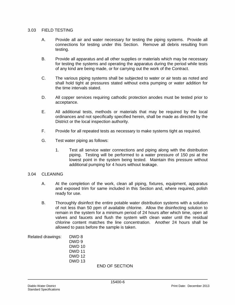
15400-6 Diablo Water District Print Date: December 2013 Standard Specifications
3.03 FIELD TESTING
A. Provide all air and water necessary for testing the piping systems. Provide all connections for testing under this Section. Remove all debris resulting from testing.
B. Provide all apparatus and all other supplies or materials which may be necessary for testing the systems and operating the apparatus during the period while tests of any kind are being made, or for carrying out the work of the Contract.
C. The various piping systems shall be subjected to water or air tests as noted and shall hold tight at pressures stated without extra pumping or water addition for the time intervals stated.
D. All copper services requiring cathodic protection anodes must be tested prior to acceptance.
E. All additional tests, methods or materials that may be required by the local ordinances and not specifically specified herein, shall be made as directed by the District or the local inspection authority.
F. Provide for all repeated tests as necessary to make systems tight as required.
G. Test water piping as follows:
1. Test all service water connections and piping along with the distribution piping. Testing will be performed to a water pressure of 150 psi at the lowest point in the system being tested. Maintain this pressure without additional pumping for 4 hours without leakage.
3.04 CLEANING
A. At the completion of the work, clean all piping, fixtures, equipment, apparatus and exposed trim for same included in this Section and, where required, polish ready for use.
B. Thoroughly disinfect the entire potable water distribution systems with a solution of not less than 50 ppm of available chlorine. Allow the disinfecting solution to remain in the system for a minimum period of 24 hours after which time, open all valves and faucets and flush the system with clean water until the residual chlorine content matches the line concentration. Another 24 hours shall be allowed to pass before the sample is taken.
Related drawings: DWD 8 DWD 9
DWD 10 DWD 11 DWD 12 DWD 13 END OF SECTION
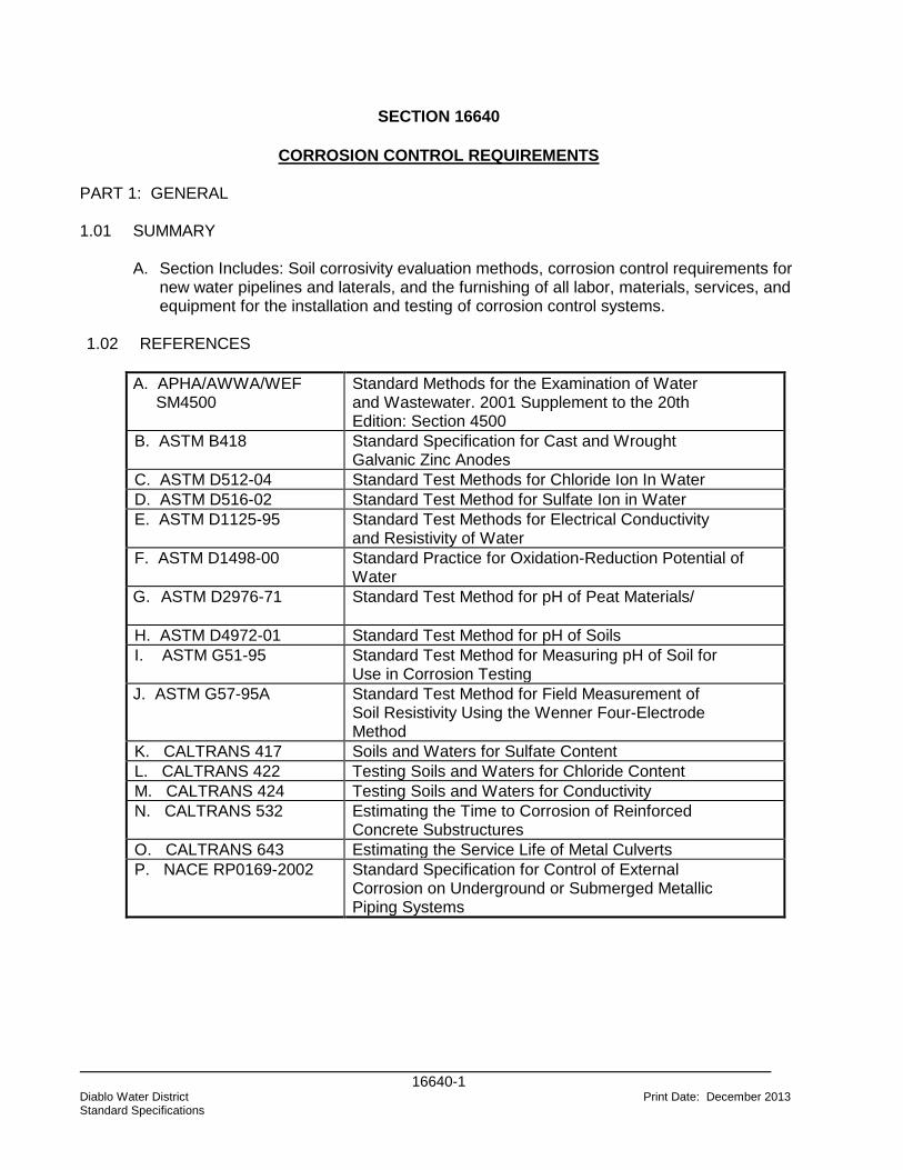
16640-1
Diablo Water District Print Date: December 2013 Standard Specifications
SECTION 16640
CORROSION CONTROL REQUIREMENTS PART 1: GENERAL 1.01 SUMMARY A. Section Includes: Soil corrosivity evaluation methods, corrosion control requirements for
new water pipelines and laterals, and the furnishing of all labor, materials, services, and equipment for the installation and testing of corrosion control systems.
1.02 REFERENCES
A. APHA/AWWA/WEF SM4500
Standard Methods for the Examination of Water and Wastewater. 2001 Supplement to the 20th Edition: Section 4500
B. ASTM B418 Standard Specification for Cast and Wrought Galvanic Zinc Anodes
C. ASTM D512-04 Standard Test Methods for Chloride Ion In Water
D. ASTM D516-02 Standard Test Method for Sulfate Ion in Water
E. ASTM D1125-95 Standard Test Methods for Electrical Conductivity and Resistivity of Water
F. ASTM D1498-00 Standard Practice for Oxidation-Reduction Potential of Water
G. ASTM D2976-71
Standard Test Method for pH of Peat Materials/
H. ASTM D4972-01 Standard Test Method for pH of Soils
I. ASTM G51-95 Standard Test Method for Measuring pH of Soil for Use in Corrosion Testing
J. ASTM G57-95A Standard Test Method for Field Measurement of Soil Resistivity Using the Wenner Four-Electrode Method
K. CALTRANS 417 Soils and Waters for Sulfate Content
L. CALTRANS 422 Testing Soils and Waters for Chloride Content
M. CALTRANS 424 Testing Soils and Waters for Conductivity
N. CALTRANS 532 Estimating the Time to Corrosion of Reinforced Concrete Substructures
O. CALTRANS 643 Estimating the Service Life of Metal Culverts
P. NACE RP0169-2002 Standard Specification for Control of External Corrosion on Underground or Submerged Metallic Piping Systems
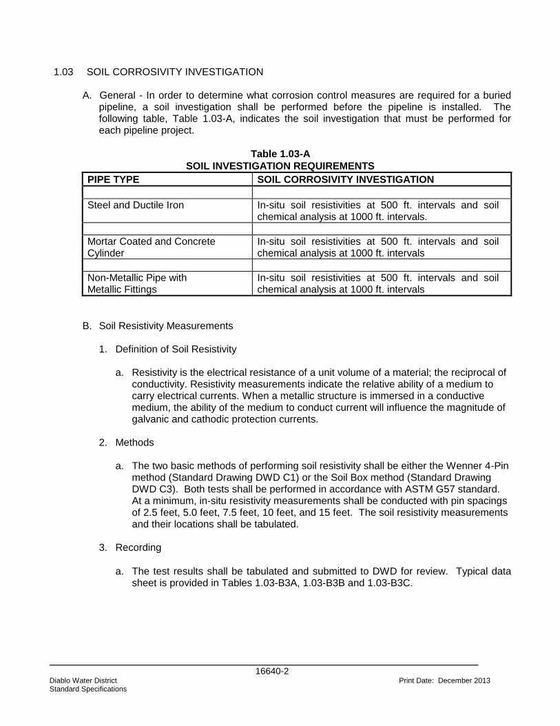
16640-2
Diablo Water District Print Date: December 2013 Standard Specifications
1.03 SOIL CORROSIVITY INVESTIGATION
A. General - In order to determine what corrosion control measures are required for a buried pipeline, a soil investigation shall be performed before the pipeline is installed. The following table, Table 1.03-A, indicates the soil investigation that must be performed for each pipeline project.
Table 1.03-A
SOIL INVESTIGATION REQUIREMENTS
PIPE TYPE SOIL CORROSIVITY INVESTIGATION
Steel and Ductile Iron In-situ soil resistivities at 500 ft. intervals and soil chemical analysis at 1000 ft. intervals.
Mortar Coated and Concrete Cylinder
In-situ soil resistivities at 500 ft. intervals and soil chemical analysis at 1000 ft. intervals
Non-Metallic Pipe with Metallic Fittings
In-situ soil resistivities at 500 ft. intervals and soil chemical analysis at 1000 ft. intervals
B. Soil Resistivity Measurements
1. Definition of Soil Resistivity
a. Resistivity is the electrical resistance of a unit volume of a material; the reciprocal of conductivity. Resistivity measurements indicate the relative ability of a medium to carry electrical currents. When a metallic structure is immersed in a conductive medium, the ability of the medium to conduct current will influence the magnitude of galvanic and cathodic protection currents.
2. Methods a. The two basic methods of performing soil resistivity shall be either the Wenner 4-Pin
method (Standard Drawing DWD C1) or the Soil Box method (Standard Drawing DWD C3). Both tests shall be performed in accordance with ASTM G57 standard. At a minimum, in-situ resistivity measurements shall be conducted with pin spacings of 2.5 feet, 5.0 feet, 7.5 feet, 10 feet, and 15 feet. The soil resistivity measurements and their locations shall be tabulated.
3. Recording
a. The test results shall be tabulated and submitted to DWD for review. Typical data
sheet is provided in Tables 1.03-B3A, 1.03-B3B and 1.03-B3C.
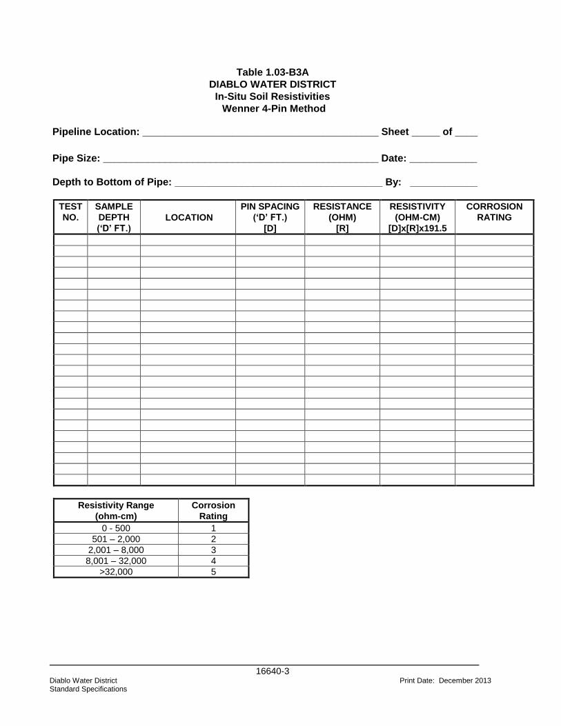
16640-3
Diablo Water District Print Date: December 2013 Standard Specifications
Table 1.03-B3A
DIABLO WATER DISTRICT
In-Situ Soil Resistivities
Wenner 4-Pin Method
Pipeline Location: __________________________________________ Sheet _____ of ____
Pipe Size: _________________________________________________ Date: ____________
Depth to Bottom of Pipe: _____________________________________ By: ____________
TEST
NO.
SAMPLE
DEPTH
(‘D’ FT.)
LOCATION
PIN SPACING
(‘D’ FT.)
[D]
RESISTANCE
(OHM)
[R]
RESISTIVITY
(OHM-CM)
[D]x[R]x191.5
CORROSION
RATING
Resistivity Range
(ohm-cm)
Corrosion
Rating
0 - 500 1
501 – 2,000 2
2,001 – 8,000 3
8,001 – 32,000 4
>32,000 5
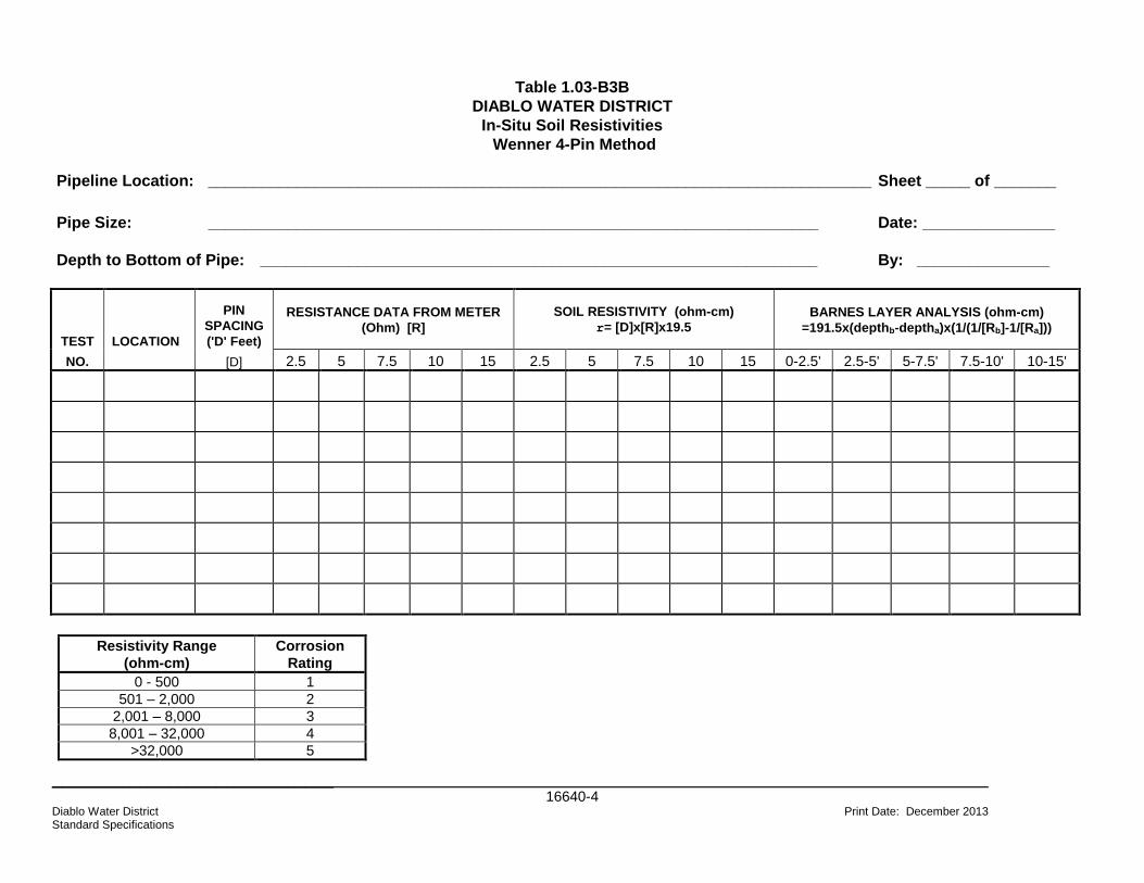
_____________________________ 16640-4
Diablo Water District Print Date: December 2013 Standard Specifications
Table 1.03-B3B
DIABLO WATER DISTRICT
In-Situ Soil Resistivities
Wenner 4-Pin Method
Pipeline Location: ___________________________________________________________________________ Sheet _____ of _______
Pipe Size: _____________________________________________________________________ Date: _______________
Depth to Bottom of Pipe: _______________________________________________________________ By: _______________
TEST LOCATION
PIN
SPACING
('D' Feet)
RESISTANCE DATA FROM METER
(Ohm) [R]
SOIL RESISTIVITY (ohm-cm)
r= [D]x[R]x19.5 BARNES LAYER ANALYSIS (ohm-cm)
=191.5x(depthb-deptha)x(1/(1/[Rb]-1/[Ra]))
NO. [D] 2.5 5 7.5 10 15 2.5 5 7.5 10 15 0-2.5' 2.5-5' 5-7.5' 7.5-10' 10-15'
Resistivity Range
(ohm-cm)
Corrosion
Rating
0 - 500 1
501 – 2,000 2
2,001 – 8,000 3
8,001 – 32,000 4
>32,000 5
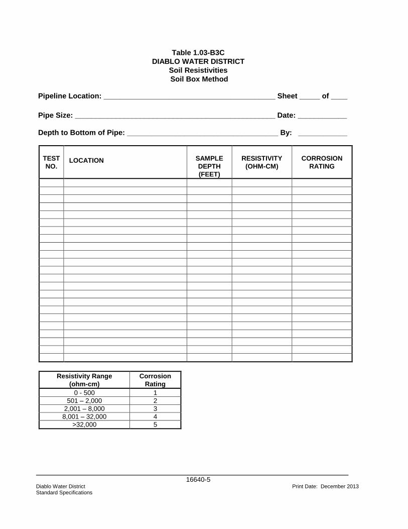
16640-5
Diablo Water District Print Date: December 2013 Standard Specifications
Table 1.03-B3C
DIABLO WATER DISTRICT
Soil Resistivities
Soil Box Method
Pipeline Location: __________________________________________ Sheet _____ of ____
Pipe Size: _________________________________________________ Date: ____________
Depth to Bottom of Pipe: _____________________________________ By: ____________
TEST
NO. LOCATION
SAMPLE
DEPTH
(FEET)
RESISTIVITY
(OHM-CM)
CORROSION
RATING
Resistivity Range
(ohm-cm)
Corrosion
Rating
0 - 500 1
501 – 2,000 2
2,001 – 8,000 3
8,001 – 32,000 4
>32,000 5
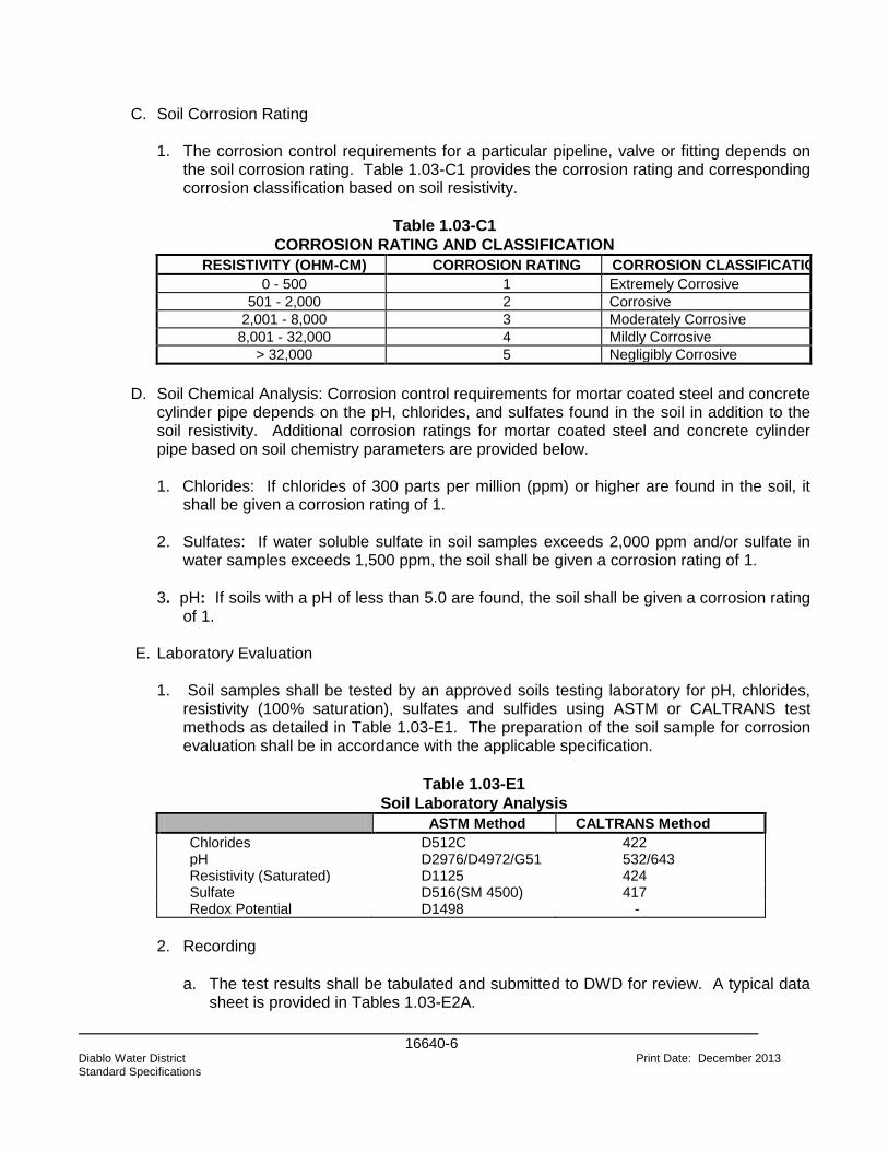
16640-6
Diablo Water District Print Date: December 2013 Standard Specifications
C. Soil Corrosion Rating 1. The corrosion control requirements for a particular pipeline, valve or fitting depends on
the soil corrosion rating. Table 1.03-C1 provides the corrosion rating and corresponding corrosion classification based on soil resistivity.
Table 1.03-C1
CORROSION RATING AND CLASSIFICATION
RESISTIVITY (OHM-CM) CORROSION RATING CORROSION CLASSIFICATION
0 - 500 1 Extremely Corrosive
501 - 2,000 2 Corrosive
2,001 - 8,000 3 Moderately Corrosive
8,001 - 32,000 4 Mildly Corrosive
> 32,000 5 Negligibly Corrosive
D. Soil Chemical Analysis: Corrosion control requirements for mortar coated steel and concrete
cylinder pipe depends on the pH, chlorides, and sulfates found in the soil in addition to the soil resistivity. Additional corrosion ratings for mortar coated steel and concrete cylinder pipe based on soil chemistry parameters are provided below.
1. Chlorides: If chlorides of 300 parts per million (ppm) or higher are found in the soil, it
shall be given a corrosion rating of 1. 2. Sulfates: If water soluble sulfate in soil samples exceeds 2,000 ppm and/or sulfate in
water samples exceeds 1,500 ppm, the soil shall be given a corrosion rating of 1.
3. pH: If soils with a pH of less than 5.0 are found, the soil shall be given a corrosion rating of 1.
E. Laboratory Evaluation 1. Soil samples shall be tested by an approved soils testing laboratory for pH, chlorides,
resistivity (100% saturation), sulfates and sulfides using ASTM or CALTRANS test methods as detailed in Table 1.03-E1. The preparation of the soil sample for corrosion evaluation shall be in accordance with the applicable specification.
Table 1.03-E1
Soil Laboratory Analysis
ASTM Method CALTRANS Method
Chlorides D512C 422 pH D2976/D4972/G51 532/643 Resistivity (Saturated) D1125 424 Sulfate D516(SM 4500) 417 Redox Potential D1498 -
2. Recording
a. The test results shall be tabulated and submitted to DWD for review. A typical data
sheet is provided in Tables 1.03-E2A.
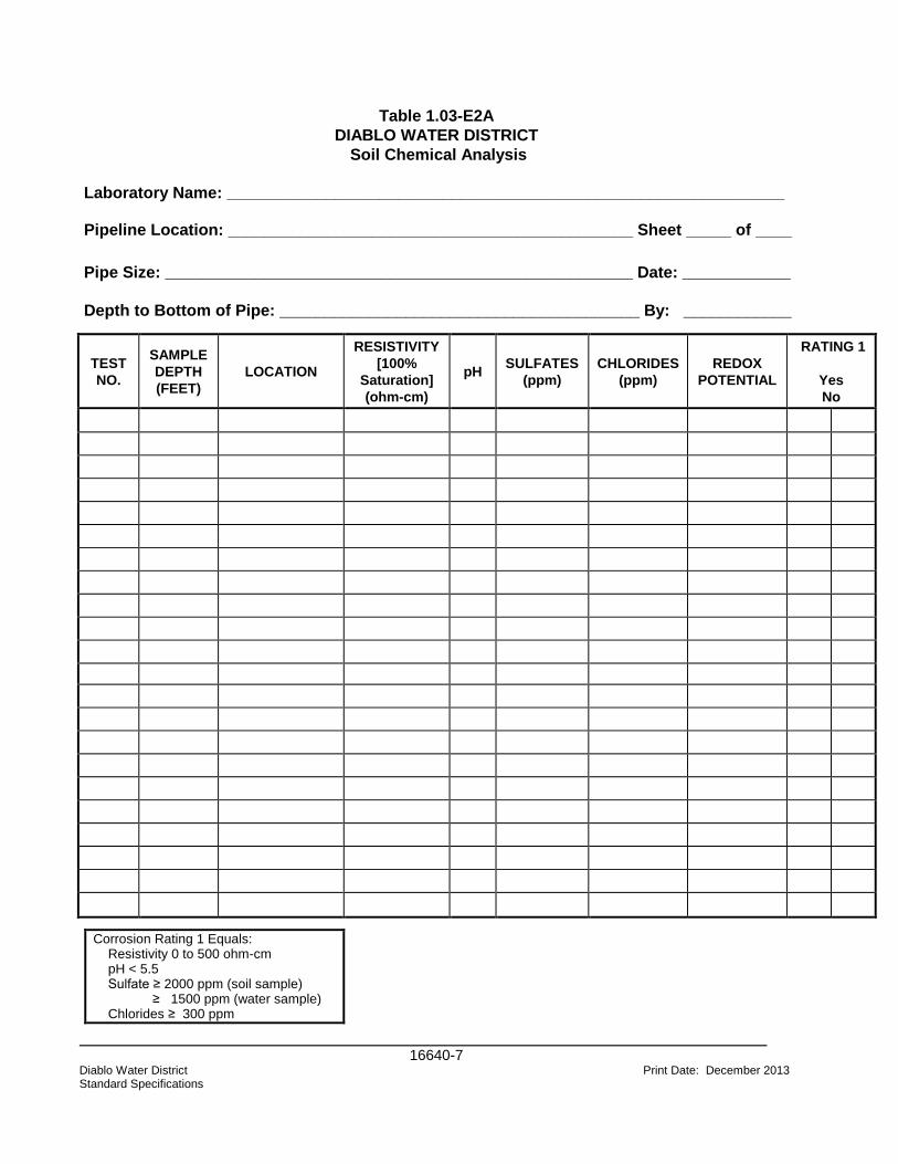
16640-7
Diablo Water District Print Date: December 2013 Standard Specifications
Table 1.03-E2A
DIABLO WATER DISTRICT
Soil Chemical Analysis
Laboratory Name: ______________________________________________________________
Pipeline Location: _____________________________________________ Sheet _____ of ____
Pipe Size: ____________________________________________________ Date: ____________
Depth to Bottom of Pipe: ________________________________________ By: ____________
TEST
NO.
SAMPLE
DEPTH
(FEET)
LOCATION
RESISTIVITY
[100%
Saturation]
(ohm-cm)
pH SULFATES
(ppm)
CHLORIDES
(ppm)
REDOX
POTENTIAL
RATING 1
Yes
No
Corrosion Rating 1 Equals: Resistivity 0 to 500 ohm-cm pH < 5.5 Sulfate ≥ 2000 ppm (soil sample) ≥ 1500 ppm (water sample) Chlorides ≥ 300 ppm
16640-8
Diablo Water District Print Date: December 2013 Standard Specifications
1.04 CORROSION CONTROL REQUIREMENTS A. General - The external corrosion control requirements for various types of pipe are based
on the soils corrosion rating as provided in Table 103-C1.
B. New Water Mains & Extensions:
1. Steel, Ductile Iron, Mortar Coated Steel and Concrete Cylinder Pipe - Each new main
extension, of any length, from an existing metallic main, shall be electrically isolated from the existing main via an isolation flange or joint. This requirement may be altered by DWD at their sole discretion. The requirements for corrosion control shall be as specified in Table 1.04-E3. If cathodic protection is required, it shall be designed by a Corrosion Engineer as specified in paragraph 1.05.
2. Non-metallic Pipe - Extensions which are constructed out of non-metallic piping material
and which utilize metallic fittings shall be provided with corrosion control as specified in Table 1.04-E3 and paragraph 1.05-A.
C. Test Station Spacing - Test stations shall be spaced at 1000 ft. maximum intervals for all
major metallic transmission and distribution metallic pipelines as directed by DWD Engineer or Corrosion Engineer. In addition, test stations may be required at the starting point and ending point for each new pipeline or extensions to existing pipelines, at crossings with foreign metallic pipelines, at cased crossings and at buried insulating flanges.
D. Copper Service Laterals - Copper service laterals shall be electrically isolated from metallic
water mains via an isolation fitting placed at the corporation stop. If copper piping is used to connect the water meter to the building or residence, the copper lateral shall also be isolated at the water meter. For soil types rated as 1 or 2, polyethylene encasement and galvanic cathodic protection shall be implemented as shown in Table 1.04-E3.
E. Non-Metallic Pipe with Metallic Fittings and Valves - Types of anodes and required anode
sizes for various types of fittings based on soil resistivity are as presented in Tables 1.04-E1 and 1.04-E2. These tables contain the minimum weights for the bare anodes which does not include the weight of the anode backfill material.

16640-9
Diablo Water District Print Date: December 2013 Standard Specifications
Table 1.04-E1
Required Zinc Anode Sizes
Soil Resistivity < 1000 ohm-cm
Pipe
Size
(inches)
Valve
(lb.)
Cross
(lb.)
Tee
(lb.)
Elbow
(lb.)
Valve
plus
Fitting*
(lb.)
Fire
Hydrant**
(lb.)
Fire
Hydrant
plus
Tee and
Valve
(lb.)
4 5 5 5 5 5 5 12 6 5 5 5 5 5 12 12 8 5 5 5 5 12 12 12 10 5 5 5 5 12 12 18 12 5 5 5 5 12 12 18
* Cross, Tee or Elbow ** Includes Elbow plus Riser
Table 1.04-E2
Required Magnesium Anode Sizes
Soil Resistivity > 1000 ohm-cm
Pipe Size
(inches)
Valve
(lb.)
Cross
(lb.)
Tee
(lb.)
Elbow
(lb.)
Valve
plus
Fitting*
(lb.)
Fire
Hydrant**
(lb.)
Fire Hydrant
plus
Tee and Valve
(lb.)
4 9 9 9 9 9 9 9 6 9 9 9 9 9 9 9 8 9 9 9 9 9 9 9 10 9 9 9 9 9 9 17 12 9 9 9 9 9 9 17
* Cross, Tee or Elbow ** Includes Elbow plus Riser
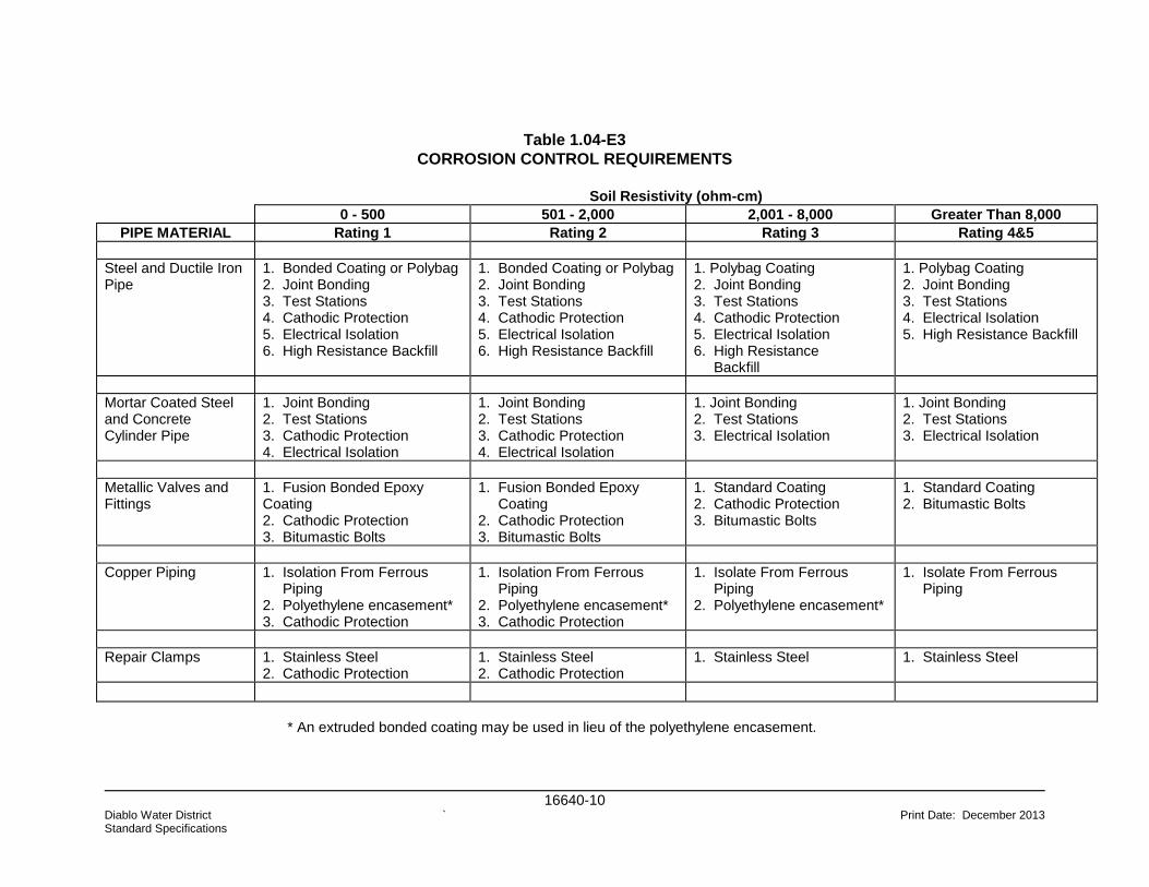
16640-10 Diablo Water District ` Print Date: December 2013 Standard Specifications
Table 1.04-E3
CORROSION CONTROL REQUIREMENTS
Soil Resistivity (ohm-cm)
0 - 500 501 - 2,000 2,001 - 8,000 Greater Than 8,000
PIPE MATERIAL Rating 1 Rating 2 Rating 3 Rating 4&5
Steel and Ductile Iron Pipe
1. Bonded Coating or Polybag 2. Joint Bonding 3. Test Stations 4. Cathodic Protection 5. Electrical Isolation 6. High Resistance Backfill
1. Bonded Coating or Polybag 2. Joint Bonding 3. Test Stations 4. Cathodic Protection 5. Electrical Isolation 6. High Resistance Backfill
1. Polybag Coating 2. Joint Bonding 3. Test Stations 4. Cathodic Protection 5. Electrical Isolation 6. High Resistance Backfill
1. Polybag Coating 2. Joint Bonding 3. Test Stations 4. Electrical Isolation 5. High Resistance Backfill
Mortar Coated Steel and Concrete Cylinder Pipe
1. Joint Bonding 2. Test Stations 3. Cathodic Protection 4. Electrical Isolation
1. Joint Bonding 2. Test Stations 3. Cathodic Protection 4. Electrical Isolation
1. Joint Bonding 2. Test Stations 3. Electrical Isolation
1. Joint Bonding 2. Test Stations 3. Electrical Isolation
Metallic Valves and Fittings
1. Fusion Bonded Epoxy Coating 2. Cathodic Protection 3. Bitumastic Bolts
1. Fusion Bonded Epoxy Coating 2. Cathodic Protection 3. Bitumastic Bolts
1. Standard Coating 2. Cathodic Protection 3. Bitumastic Bolts
1. Standard Coating 2. Bitumastic Bolts
Copper Piping 1. Isolation From Ferrous Piping 2. Polyethylene encasement* 3. Cathodic Protection
1. Isolation From Ferrous Piping 2. Polyethylene encasement* 3. Cathodic Protection
1. Isolate From Ferrous Piping 2. Polyethylene encasement*
1. Isolate From Ferrous Piping
Repair Clamps 1. Stainless Steel 2. Cathodic Protection
1. Stainless Steel 2. Cathodic Protection
1. Stainless Steel 1. Stainless Steel
* An extruded bonded coating may be used in lieu of the polyethylene encasement.
16640-11 Diablo Water District Print Date: December 2013 Standard Specifications
1.05 DESIGN
A. Cathodic Protection System Design - Cathodic protection system designs for distribution
and transmission pipelines will be performed and stamped by a qualified Corrosion Engineer. This person shall be responsible for the design, supervision, inspection and testing of the cathodic protection system. Corrosion Engineer refers to a person who is either a licensed Professional Corrosion Engineer in the state of California or certified as a “Cathodic Protection Specialist” by the National Association of Corrosion Engineers (NACE). The qualifications for the Corrosion Engineer shall be submitted to DWD for approval prior to commencement of the design work.
PART 2: PRODUCTS
2.01 GENERAL
A. Materials and workmanship shall be in accordance with all applicable state and local
codes. The use of a manufacturer's name and model or catalog number is only for the purpose of establishing the standard of quality and general configuration desired. Products of other manufacturers will be considered.
2.02 JOINT BOND WIRES
A. Joint bond wires shall be single-conductor, stranded copper wire with 600-volt HMWPE
insulation. Supply all joint bonds complete with a formed copper sleeve on each end of the wire.
1. Push-on, Mechanical, Ball or Flanged Joints--No.4 AWG wires, 18 inches long. 2. Flexible Coupling Joints--No.4 AWG wires, 24 inches long, with two 12-inch long
insulated No. 8 AWG wire pigtails. 3. Insulated Flexible Coupling Joints--No. 4 AWG wire, 18-inch long, with one 12-inch long
No.8 AWG wire pigtail. 4. Concrete Cylinder Pipe--Joint bonds shall be supplied by the manufacturer and shall
include the following: a.) Shop manufactured rod-cable-rod bonding cable as shown in the details. Rods shall be
welded to the bell-and-spigot on opposite sides of the pipe at the spring line of the pipe. b.) AWG bond wires, for each joint. Total resistance of the bond or bonds at each joint
shall not be greater than 120 percent of the linear resistance of a pipe section. 5. No. 8 AWG/HMWPE cables may be used to bond joints when galvanic anode systems
are utilized, and to bond metallic fittings on nonmetallic piping systems.

16640-12 Diablo Water District Print Date: December 2013 Standard Specifications
2.03 GALVANIC ANODES: A. High Potential Magnesium Alloy: (Soil resistivities > 1000 ohm-cm) Composition: Aluminum 0.010%Max Manganese 0.5 to1.30% Zinc 0 Silicon 0 Copper 0.02% Max Nickel 0.001% Max Iron 0.03% Max Total Others 0.05% each or 0.3% Max Total Magnesium Remainder B. Zinc Anodes (ASTM B418, Type II): (Soil resistivities < 1000 ohm-cm) Composition: Iron 0.0014% Max Cadmium 0.003% Max Aluminum 0.005% Max Lead 0.003% Max Copper 0.002% Max Zinc Remainder
C. Furnish a laboratory analysis guaranteeing that all anodes supplied meet all the
requirements of this Specification. D. Supply each anode with No. 12 AWG solid copper wire with THHN insulation, 10-feet
long. E. Silver braze the wire to a galvanized steel rod or strap which is cast into the anode.
Seal this connection completely with electrical potting compound. The anode connection
shall be stronger than the wire.
F. Anode Backfill Composition: Ground Hydrated Gypsum 75 percent Powdered Wyoming Bentonite 20 percent Anhydrous Sodium Sulfate 5 percent G. Anode Backfill
1. Anode backfill shall have a grain size so that 100 percent is capable of passing
through a 20-mesh screen and 50 percent will be retained by a 100-mesh screen. The backfill mixture shall be thoroughly mixed and firmly packaged around the galvanic anode within the cloth bag by means of adequate vibration. Provide anode packaged in a plastic or heavy paper bag of sufficient thickness to protect the anode, backfill, and cloth bag during normal shipping and handling.
16640-13 Diablo Water District Print Date: December 2013 Standard Specifications
2.04 CATHODIC PROTECTION TEST STATIONS A. Flush mounted test boxes shall have a concrete body cast with a cast iron ring, with a
minimum weight of 55 pounds and minimum dimensions of 8-inch inside diameter and 12-inch length. Brooks Type 1RT Traffic Box, or approved equal. Provide with a 12-pound cast iron lid with the words "CP-Test" cast into the lid.
B. Terminal boxes shall be high-impact molded Lexan plastic, Model “Big Fink” as
manufactured by Cott manufacturing Company or approved equal. The test box shall be provided with sufficient terminals for each cable. Provide terminal block with nickel-plated brass studs, washers, and lock washers.
2.05 TEST STATION WIRE
A. Wire shall be single conductor, No. 10 AWG stranded copper with 600-volt TW, THWN,
or THHN insulation and single-conductor, No. 8 AWG stranded copper with 600-volt TW, THWN, or THHN insulation.
2.06 PERMANENT REFERENCE ELECTRODES
A. Prepackaged Reference Electrodes
1. Prepackaged Copper-Copper Sulfate Reference Electrode
2. Prepackaged Zinc Reference Electrode a. Material: ASTM B418, Type II.
b. Dimensions: 1.4 inches by 1.4 inches by 9 inches. B. Wire: No. 12 AWG stranded copper wire with yellow, 600-volt TW, THWN, or THHN
insulation. The wire shall be a minimum of 25 feet long and attached to the electrode core by the manufacturer's standard connection. Connection shall be stronger than the wire.
C. Backfill: 50 percent gypsum, 50 percent bentonite, in a permeable cloth bag, or
approved equivalent. D. Packaging: Provide electrode packaged in a plastic or heavy paper bag of sufficient
thickness to protect the electrode, backfill, and cloth bag during normal shipping and handling.
2.07 SHUNTS
A. Anode metering shunts shall be 0.01 ohm, 6 amp capacity with 1% accuracy.
16640-14 Diablo Water District Print Date: December 2013 Standard Specifications
2.08 EXOTHERMIC WELD MATERIALS A. Exothermic weld materials shall consist of wire sleeves, welders, and weld cartridges
according to the weld manufacturer's recommendations for each wire size and pipe or fitting size and material. All welding materials and equipment shall be the product of a single manufacturer such as “Cadweld” by Erico Products, Inc., “Thermoweld” by Continental Industries, Inc., or approved equal. Each cable shall be fitted with a copper sleeve for accomplishing the weld. Interchanging materials of different manufacturers is not acceptable.
2.09 GROUND CLAMP
A. Ground clamp shall be sized to fit the copper tubing and wire size, made out of high
copper alloy, and rated for direct burial.
2.10 EXOTHERMIC WELD CAPS A. Coating material for cable-to-pipe connections shall be Handicaps as manufactured by
Royston Products or Propoxy 20 epoxy putty as manufactured by the Hercules Chemical Company or approved equal.
2.11 WIRE CONNECTORS
A. One-piece, tin-plated crimp-on ring connector.
2.12 INSULATED JOINTS
A. Insulating joints shall be dielectric unions, flanges, or couplings. The complete assembly
shall have an ANSI rating equal to or higher than that of the joint and pipeline. All materials shall be resistant to the intended exposure, operating temperatures, and
products in the pipeline.
1. Gaskets--1/8” thick full-faced neoprene faced phenolic. 2. Insulating Sleeves--Full-length 1/32” thick Grade G-10 fiberglass epoxy. 3. Insulating Washers--5/32” thick Grade G-10 fiberglass epoxy. 4. Washers--Same material as bolts, 1/8-inch thick.
2.13 CASING INSULATORS A. Casing insulators shall be molded high-density polyethylene with plastic runners and
shall consist of bolted segments, complete with stainless steel bolts for assembly.
2.14 CASING SEALS A. Casing seals shall be flexible molded rubber seals and shall be supplied complete with
two stainless bands for sealing. Split seals are not acceptable.
16640-15 Diablo Water District Print Date: December 2013 Standard Specifications
2.15 WALL SEALS A. Wall seals shall be interlocking links of molded synthetic rubber. The links are to be
connected together with stainless steel bolts. The wall seal shall be sized for the pipe size and type and the wall hole.
2.16 PIPE BACKFILL
A. Imported backfill placed around the pipes shall be a good quality sand backfill with a
minimum resistivity greater than 5,000 ohm-cm, a minimum pH greater than 6.0, a maximum chloride concentration less than 300 ppm and a maximum sulfate concentration less than 1,000 ppm.
2.17 COATINGS FOR BURIED INSULATING FLANGES
A. Coat buried insulating flanges with Trenton Wax Tape#1 by The Trenton Corporation or
approved equal.
PART 3: EXECUTION 3.01 GENERAL
A. Installation of the specified corrosion control materials shall conform to the guidelines as
set forth herein. Any changes in design or method of installation of any item as specified shall be reviewed and approved by DWD Engineer prior to installation.
3.02 PIPE JOINT BONDING
A. Bond all buried non-welded, rubber gasket joints, mechanical joints and fusion-bonded
epoxy coated flanges for continuity. Install one or two joint bond wire assemblies at each joint that requires bonding, in accordance with Table 1.04-E3, of this document and the following:
B. The electrical connection of all wires to pipes and fittings shall be performed using the
exothermic welding process.
3.03 EXOTHERMIC WELDS A. Exothermic weld connections shall be installed in accordance with Standard Drawing
DWD-C6. Coating materials shall be removed from the surface over an area just sufficient to allow proper searing of the graphite weld mold to the pipe surface. The coating shall be entirely removed in the area of the actual weld by using a sanding wheel or metal file. White metal shall be achieved free from resin films. After the weld is complete, strike the weld with a hammer using a moderate amount of force. Welds
Pipe Size No. Of Bond Wires Required
Smaller than 20-in diameter 1
20-inch diameter & larger 2

16640-16 Diablo Water District Print Date: December 2013 Standard Specifications
that dislodge from the pipe surface shall be replaced. Care shall be taken to prevent damage to the wires. All rough edges of the weld and slag shall be removed during this structural test. Spray primer on all bare metal. Cover connection and exposed structure surface with a plastic cap and bitumastic.
3.04 ANODE STORAGE AND HANDLING
A. Store all prepackaged anodes off the ground and keep them dry at all times. Protect
them against weather, condensation, and mechanical damage. Immediately remove all wet or mechanically damaged prepackaged anodes from the site. Prepackaged anodes shall be handled with care to prevent loss of backfill material. Anodes shall not be lifted or installed by the lead wire.
3.05 GALVANIC ANODE INSTALLATION
A. Remove the plastic or heavy paper bag used for shipping. The cloth bag shall remain
around the anode. Care shall be exercised during installation to prevent damage to the cloth bag and loss of backfill material. After placing anodes in the trench, native soil, free of rocks and other foreign objects shall be placed around the anode to a minimum cover of one foot above the anode. Anode shall then be flooded with 5 gallons of fresh water. The remainder to the trench shall then be backfilled with native soil. Install galvanic anodes 1 foot below the pipe invert and at a minimum distance of 3 feet from the pipeline, valve or fitting. Provide a minimum anode spacing of 5 feet from other unprotected pipelines. Install anodes at intervals determined by the cathodic protection design.
B. Anode Location
1. Location of anodes shall be determined by cathodic protection design.
C. Valves and Fittings for Non-metallic Pipe 1. Each buried ductile/cast iron and steel fitting, and valve used in conjunction with
nonmetallic pipe shall be cathodically protected with zinc anodes (soil resistivity < 1000 ohm-cm) or magnesium anodes (soil resistivity > 1000 ohm-cm). Where two or more metallic fittings are adjacent to each other, they can be bonded together for the purposes of cathodic protection as shown on the Standard Drawings.
2. Anode connections to ductile/cast iron and steel fittings and valves shall be made by
the exothermic weld method. Any damage to the interior coating shall be repaired in accordance with the manufacturer's recommendations.
3.06 WIRES
A. Provide a minimum cover of 30 inches over all cables. Use care during installation to
avoid punctures, cuts and similar damage to the insulation. Replace entire cable run where any damage to insulation occurs. Yellow caution tape shall be placed a minimum of 6 inches above any buried cables.
16640-17 Diablo Water District Print Date: December 2013 Standard Specifications
3.07 TEST STATION INSTALLATION A. Test stations shall be installed as shown on the Standard Drawings. A concrete collar
shall be set flush with the top of curb or finish grade in paved areas and two inches above grade in landscaped areas. The terminal end of each cable shall be identified with permanent cable markers as shown in the Standard Drawings. The locations for the test stations shall be as specified in the cathodic protection design.
B. Provide a minimum of 18 inches of slack for each cable in each test station. Sufficient
slack shall be provided to allow removal of the terminal box from the test station without disconnecting any of the cables.
3.08 INSULATING FLANGED JOINTS
A. All insulating components of the insulating flanged gasket set shall be cleaned of all dirt,
grease oil and other foreign materials immediately prior to assembly. Bolt holes in mating flanges shall be properly aligned at the time bolts and insulating sleeves are inserted to prevent damage to the insulation. After flanged bolts have been tightened, each insulating washer shall be inspected for cracks or other damage. All damaged washers shall be replaced. After assembly, resistance between each bolt and flange shall be measured with an approved ohmmeter and the minimum resistance shall be 50,000 ohms. Where the insulating joint is assembled in the shop and shipped as a unit, resistance shall be measured in the shop between the flanges and between each bolt and flange and shall meet the above requirements. All below grade insulating joints shall be coated as specified above.
3.09 COATING BURIED INSULATING FLANGED JOINTS
A. Surfaces shall be cleaned of all dirt, grease, oil and other foreign materials immediately prior to coating. Remove loose rust, paint and other foreign matter in accordance with SSPC SP2 or SP3. A prime coating shall be applied in a uniform coating over the entire surface to be wrapped. A liberal coating shall be applied to threads, cavities, shoulders, pits and other irregularities. A fill coating shall be molded and packed onto irregular surfaces such as flanges, valves or flexible couplings to create a smooth profile prior to wrapping. A wrap coating shall be spiral wrapped using a minimum of 55 percent overlap to ensure a double thickness of material. At the completion of each roll the overlaps shall be smoothed by hand in the direction of the spiral to ensure sealing of the overlap. A 2- inch overlap shall be maintained when overlapping one roll with the end of a new roll. Overlap shall occur on the top half of the pipeline. A guard coating shall be spiral over-wrapped using a 55 percent overlap to ensure a double coating.
3.10 CASING INSULATOR AND SEALS
A. At all locations where water system piping is cased with metal casing, casing insulators
and end seals shall be installed. Type and spacing of insulators required shall be at manufacturer's written recommendations and depend on type and size of casing and carrier pipe.
16640-18 Diablo Water District Print Date: December 2013 Standard Specifications
3.11 TESTING
A. The Contractor shall furnish all necessary equipment, material, and qualified personnel
required to perform all tests described herein. B. Electrical Continuity Testing 1. Conduct continuity testing on all buried joints that are required to be bonded both
before backfilling and after backfilling.
2. Before Backfilling
a. The Contractor shall test electrical continuity of completed joint bonds before backfilling using a digital low resistance meter.
3. Test Procedure Before Backfilling
a. Measure the resistance of joint bonds with the low resistance ohmmeter in accordance with the manufacturer’s written instructions. Use the helical hand spikes to contact the pipe on each side of the joint without touching the exothermic weld or the bond. The contact area shall be cleaned to bright metal by filing or grinding and be without any surface rusting or oxidation.
4. Record Keeping Before Backfilling
a. Records shall be made of each bonded pipeline during the test and submitted to
the Manager. These records shall include description and size of pipeline tested, date tested, joint type, number of joint bonds, joint bond resistance.
5. Acceptable Resistance Before Backfilling a. The continuity resistance will not be accepted if calculated to be greater than 120
percent of theoretical resistance of the bond cable. The resistance of the bond cables shall be obtained from the bond cable manufacturer. Any bonded joint which exceeds 120 percent of the theoretical resistance shall be replaced and retested for compliance.
6. After Backfilling a. The Contractor shall retest the continuity on all pipelines required to be bonded
after the pipeline has been buried. 7. Test Procedure After Backfilling a. Test current shall be circulated through the pipeline using the No. 8 wires in the
test stations. Wire size shall be determined by the Contractor and shall be sized for the test current (minimum of 25 amperes). The continuity resistance shall be calculated as an average per joint for the section being tested.
16640-19 Diablo Water District Print Date: December 2013 Standard Specifications
8. Record Keeping After Backfilling a. Records shall be made of each section of bonded pipe during the test and
submitted to DWD. These records shall include description, location, and size of pipeline tested, starting location and direction of test, date of test, resistance of pipe per foot, length of pipe tested, measured resistance, calculated resistance, and percent of variance.
9. Acceptable Resistance After Backfilling a. The continuity resistance will not be accepted if calculated to be more than 120
percent of the theoretical resistance per joint. The resistance of the pipe per foot shall be obtained from the pipe manufacturer. The resistance of the joints shall be obtained from the bond cable manufacturer. If a section of pipe does not pass the continuity test, the Contractor shall locate the defective joint bond and repair it. After repairing, the continuity of that section will be retested.
C. Insulation Joints and Casings 1. The Contractor shall test each insulated joint and cased crossing. All damaged or
defective insulation parts shall be replaced and retested. All electrical shorts to the casing shall be cleared and retested. Records shall be made of all insulated joints and cased crossing test and submitted to DWD for approval.
D. Test Stations 1. The Contractor shall test all test leads to ensure they were installed in accordance
with the specifications. All defective test leads shall be repaired and/or replaced and retested. Records shall be made of all test stations tested and submitted to DWD for approval.
E. Cathodic Protection System 1. The Contractor shall test all cathodically protected pipelines to ensure that the
protection levels are within the most recent NACE RP0169-2002 standards. Records shall be made of all anode current output and pipe to-soil potential measurements performed and submitted to DWD for approval.
F. Acceptance
1. All tests performed shall be reviewed and approved by DWD Engineer before the corrosion control work is accepted. DWD reserves the right to spot check any or all tests performed by the Contractor. All construction defects must be repaired and retested before the final acceptance is made. All unacceptable tests shall be retested by the Contractor at no additional cost to DWD.
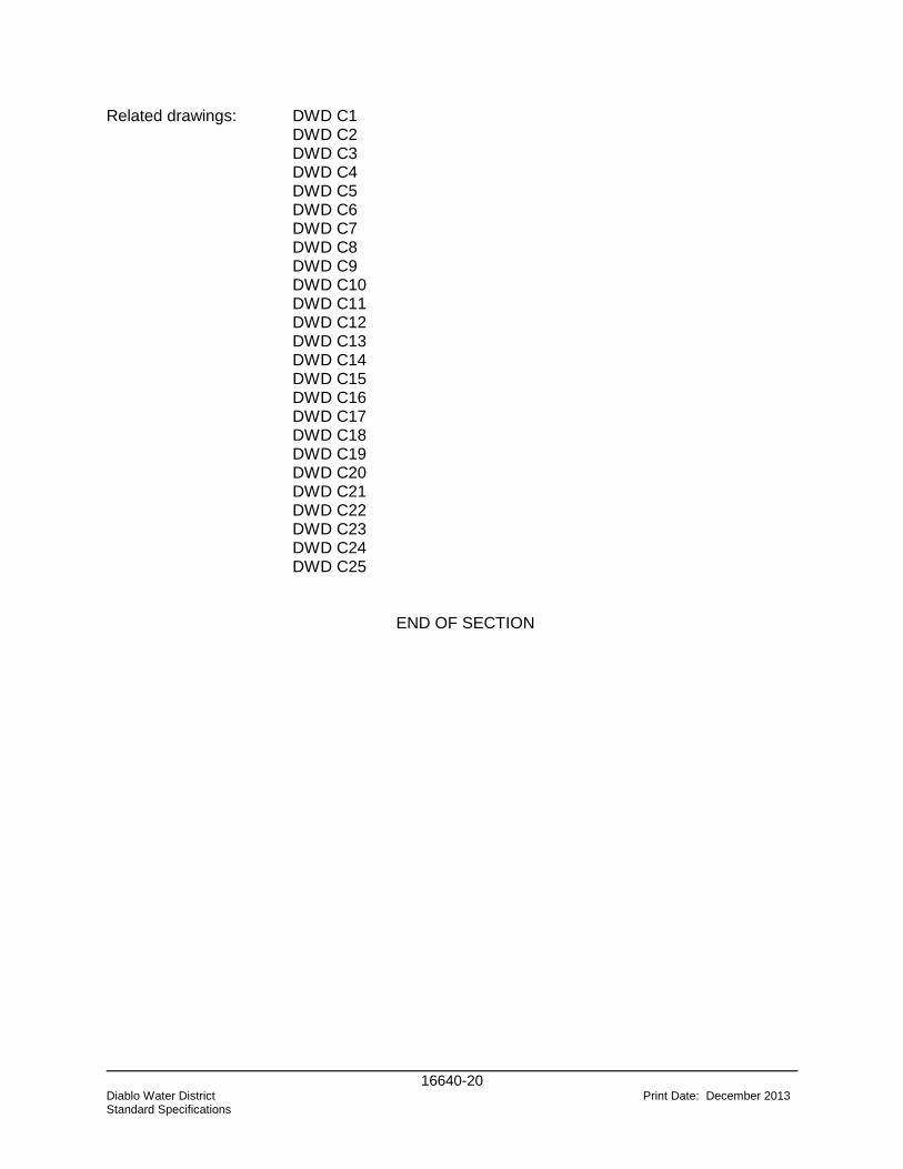
16640-20 Diablo Water District Print Date: December 2013 Standard Specifications
Related drawings: DWD C1 DWD C2 DWD C3 DWD C4 DWD C5 DWD C6 DWD C7 DWD C8 DWD C9 DWD C10
DWD C11 DWD C12 DWD C13 DWD C14 DWD C15 DWD C16 DWD C17 DWD C18 DWD C19 DWD C20 DWD C21 DWD C22 DWD C23 DWD C24 DWD C25
END OF SECTION

6. Standard Drawings
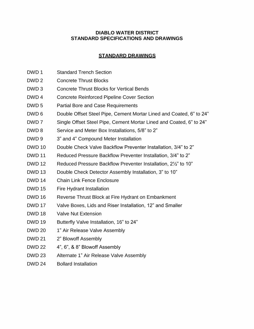
DIABLO WATER DISTRICT STANDARD SPECIFICATIONS AND DRAWINGS
STANDARD DRAWINGS
DWD 1 Standard Trench Section
DWD 2 Concrete Thrust Blocks
DWD 3 Concrete Thrust Blocks for Vertical Bends
DWD 4 Concrete Reinforced Pipeline Cover Section
DWD 5 Partial Bore and Case Requirements
DWD 6 Double Offset Steel Pipe, Cement Mortar Lined and Coated, 6” to 24”
DWD 7 Single Offset Steel Pipe, Cement Mortar Lined and Coated, 6” to 24”
DWD 8 Service and Meter Box Installations, 5/8” to 2”
DWD 9 3” and 4” Compound Meter Installation
DWD 10 Double Check Valve Backflow Preventer Installation, 3/4” to 2”
DWD 11 Reduced Pressure Backflow Preventer Installation, 3/4” to 2”
DWD 12 Reduced Pressure Backflow Preventer Installation, 2½” to 10”
DWD 13 Double Check Detector Assembly Installation, 3” to 10”
DWD 14 Chain Link Fence Enclosure
DWD 15 Fire Hydrant Installation
DWD 16 Reverse Thrust Block at Fire Hydrant on Embankment
DWD 17 Valve Boxes, Lids and Riser Installation, 12” and Smaller
DWD 18 Valve Nut Extension
DWD 19 Butterfly Valve Installation, 16” to 24”
DWD 20 1” Air Release Valve Assembly
DWD 21 2” Blowoff Assembly
DWD 22 4”, 6”, & 8” Blowoff Assembly
DWD 23 Alternate 1” Air Release Valve Assembly
DWD 24 Bollard Installation

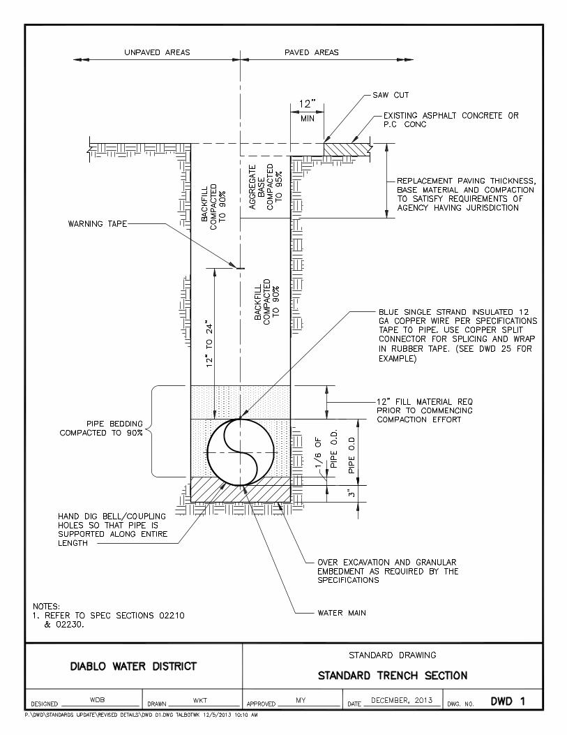
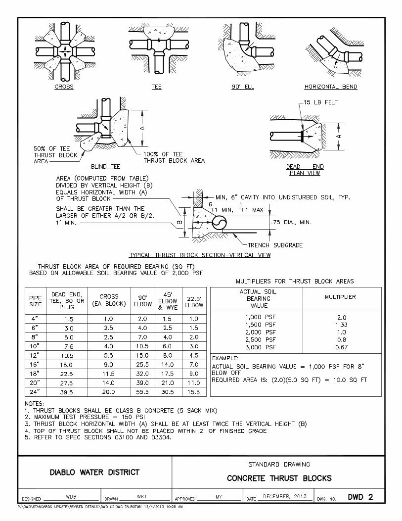
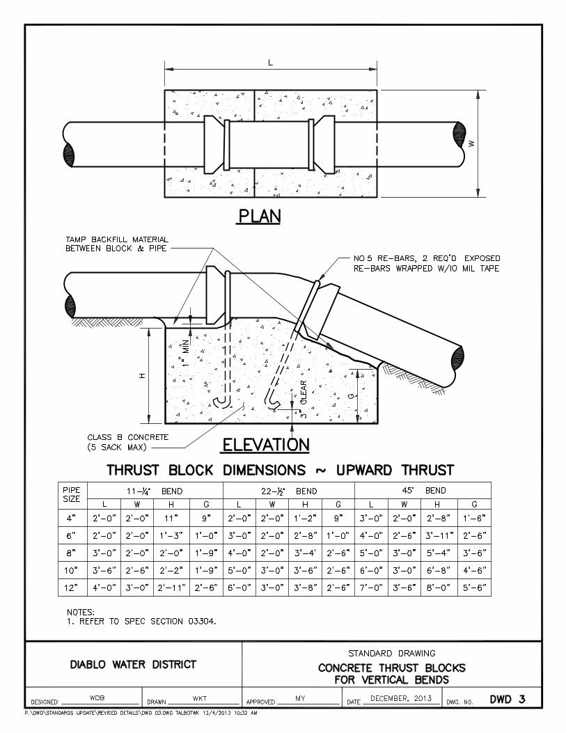
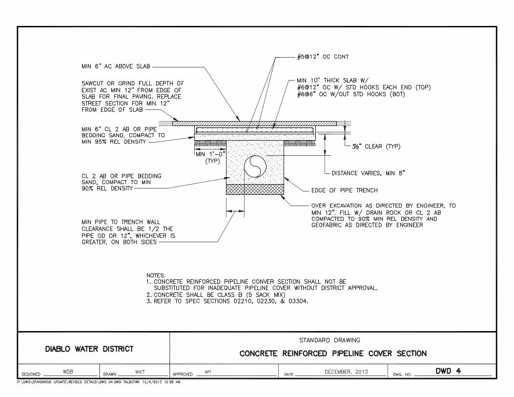
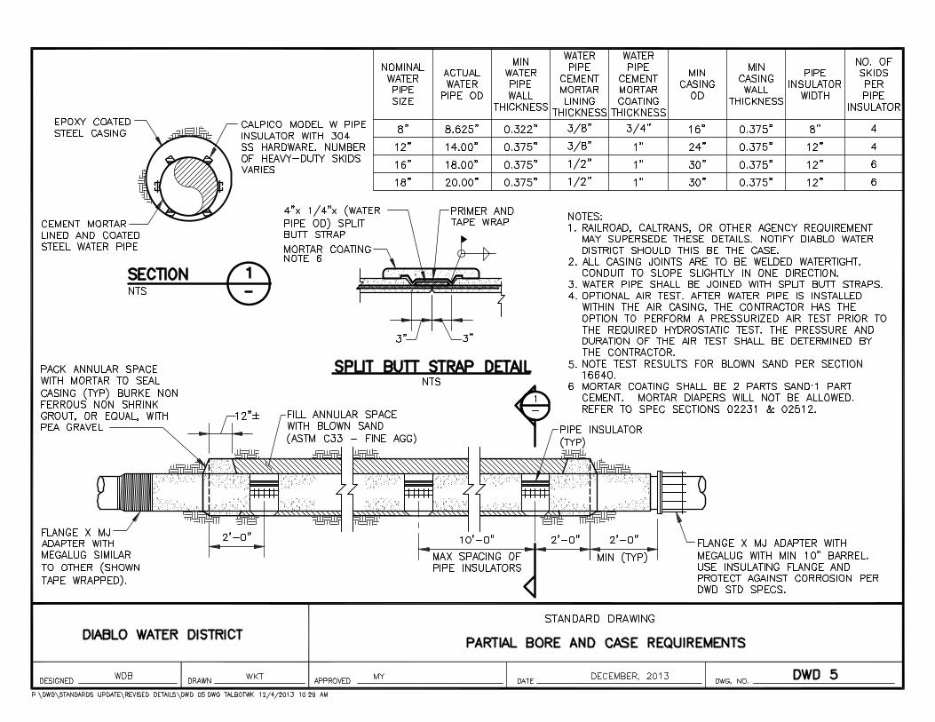
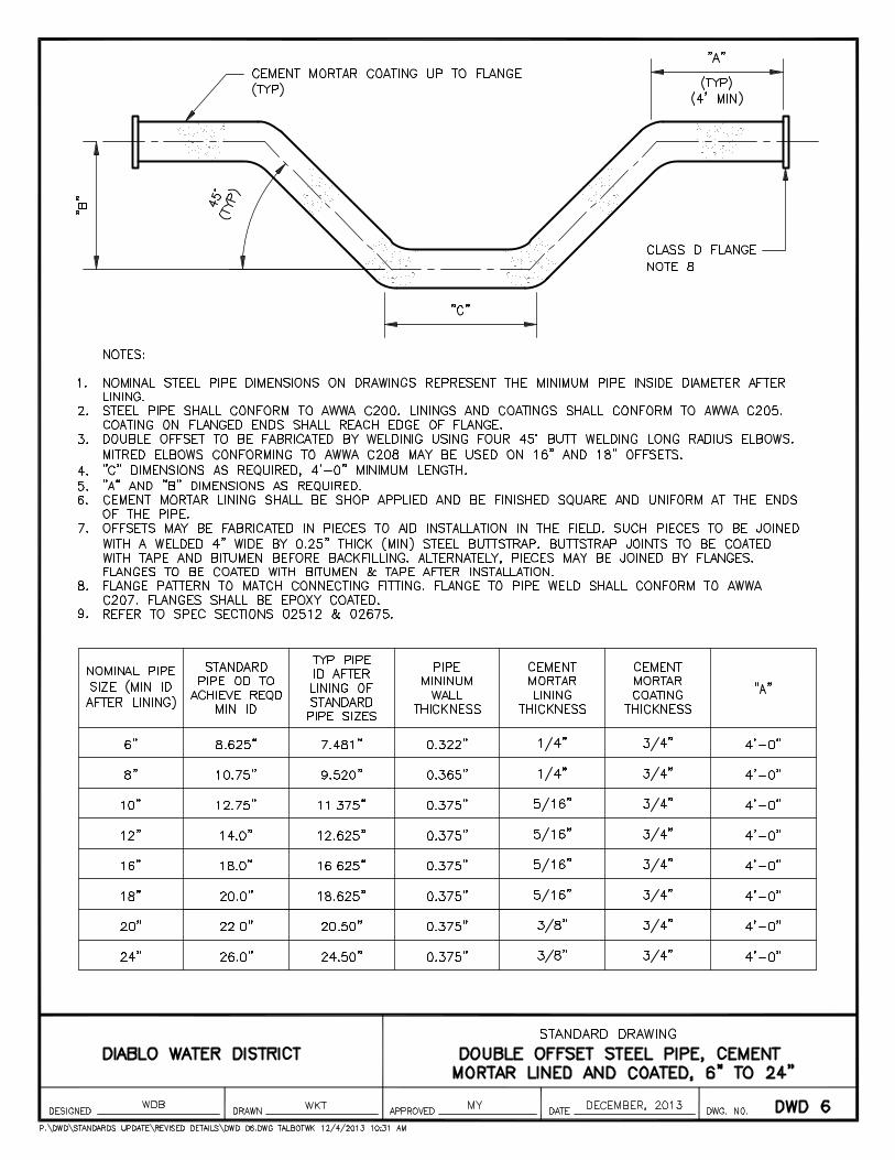
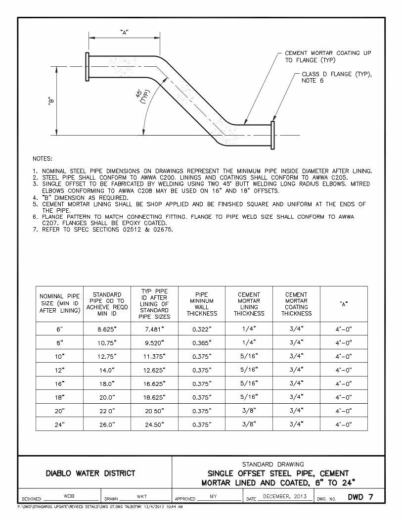
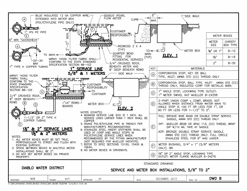
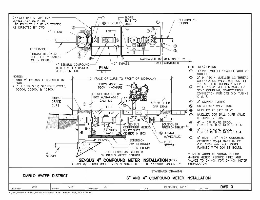
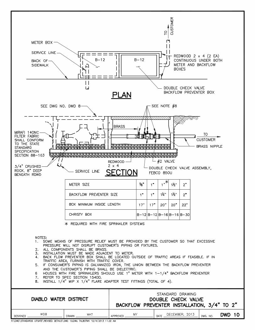

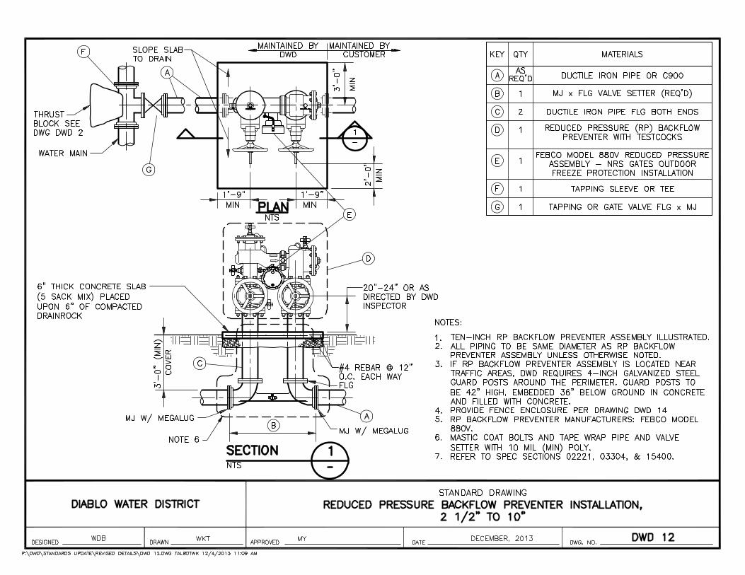
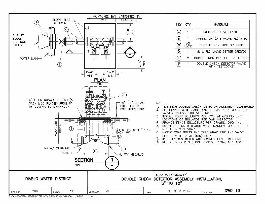
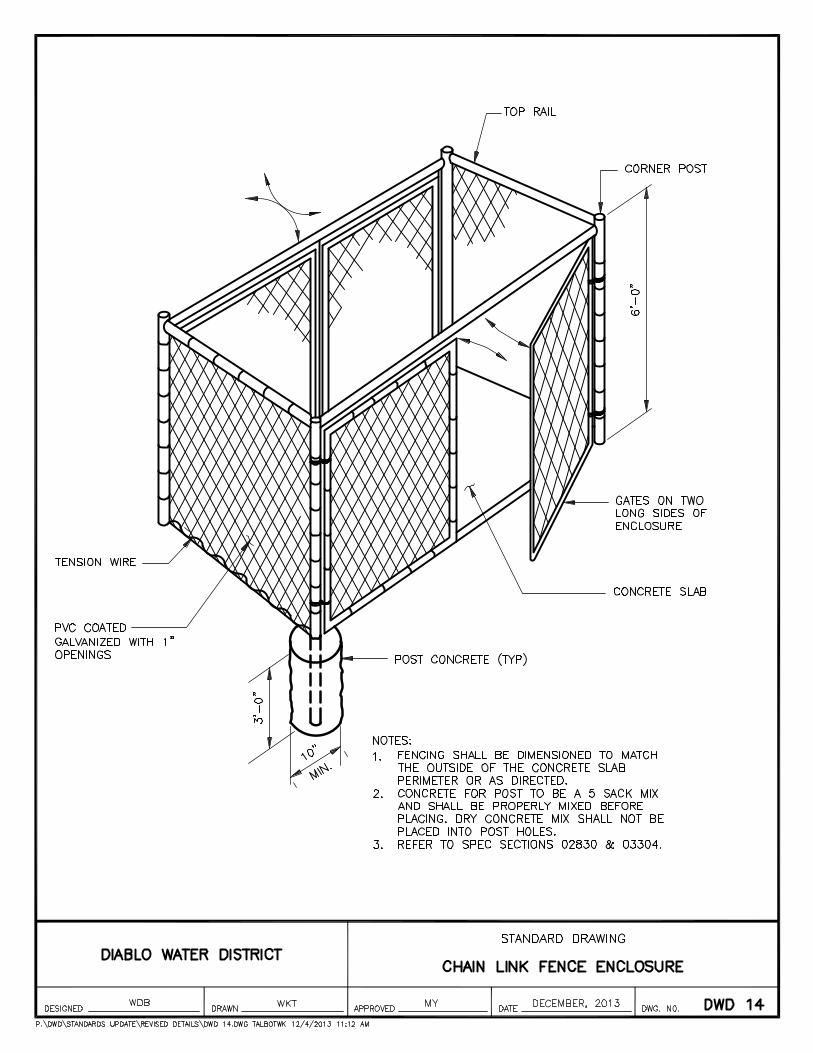
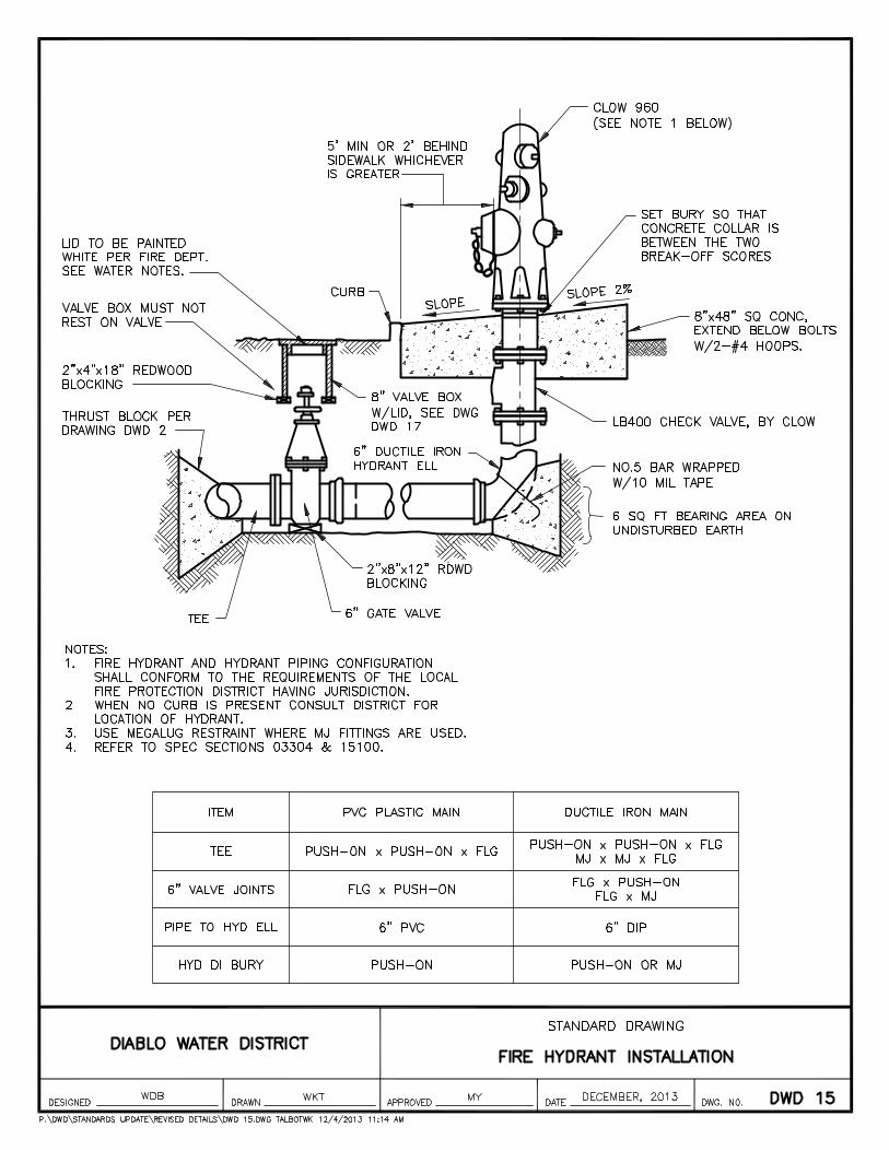
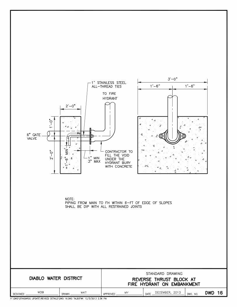
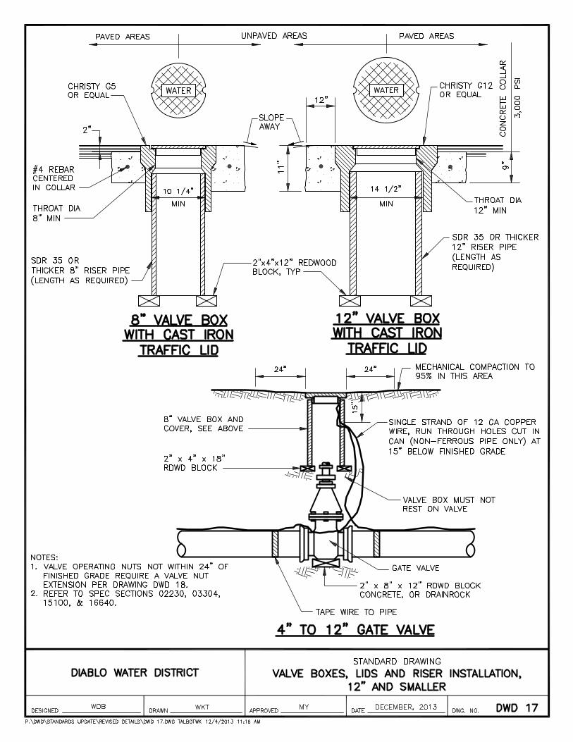
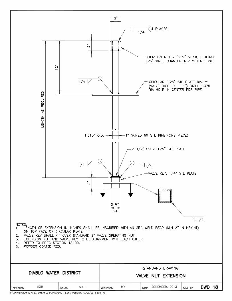
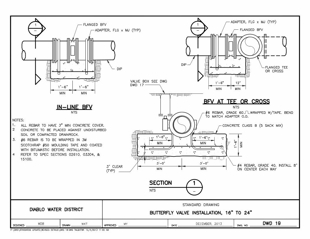
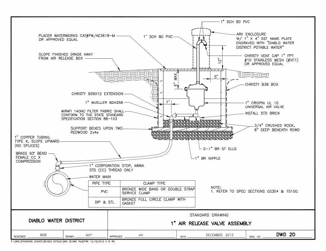
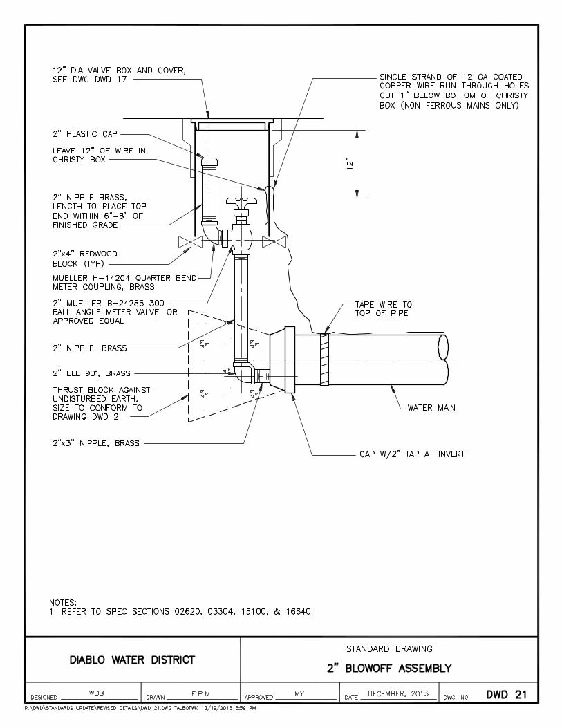
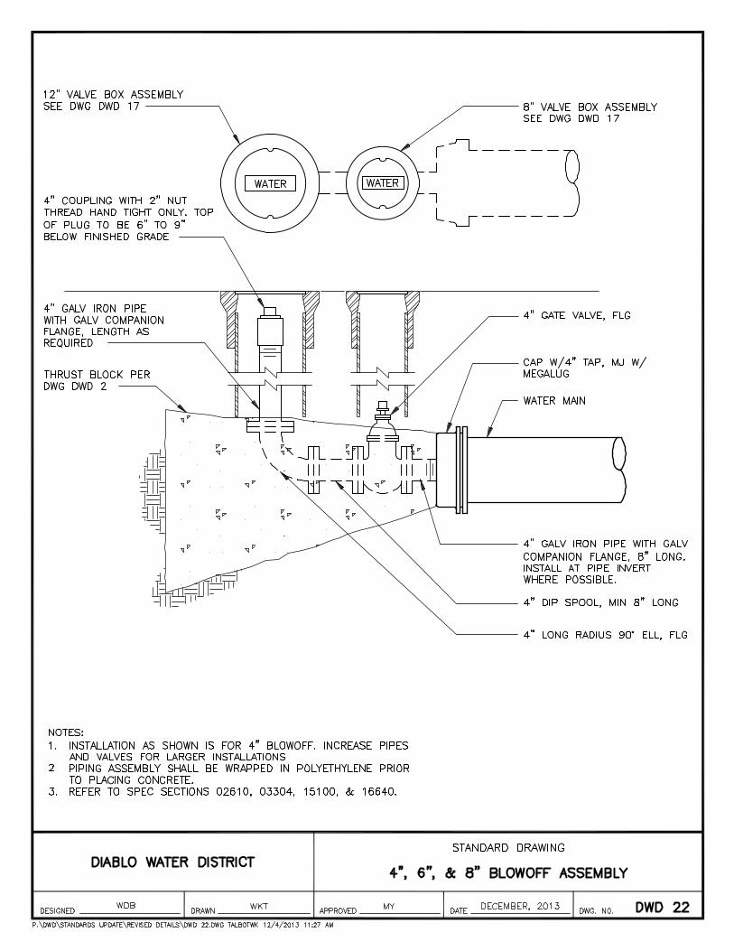
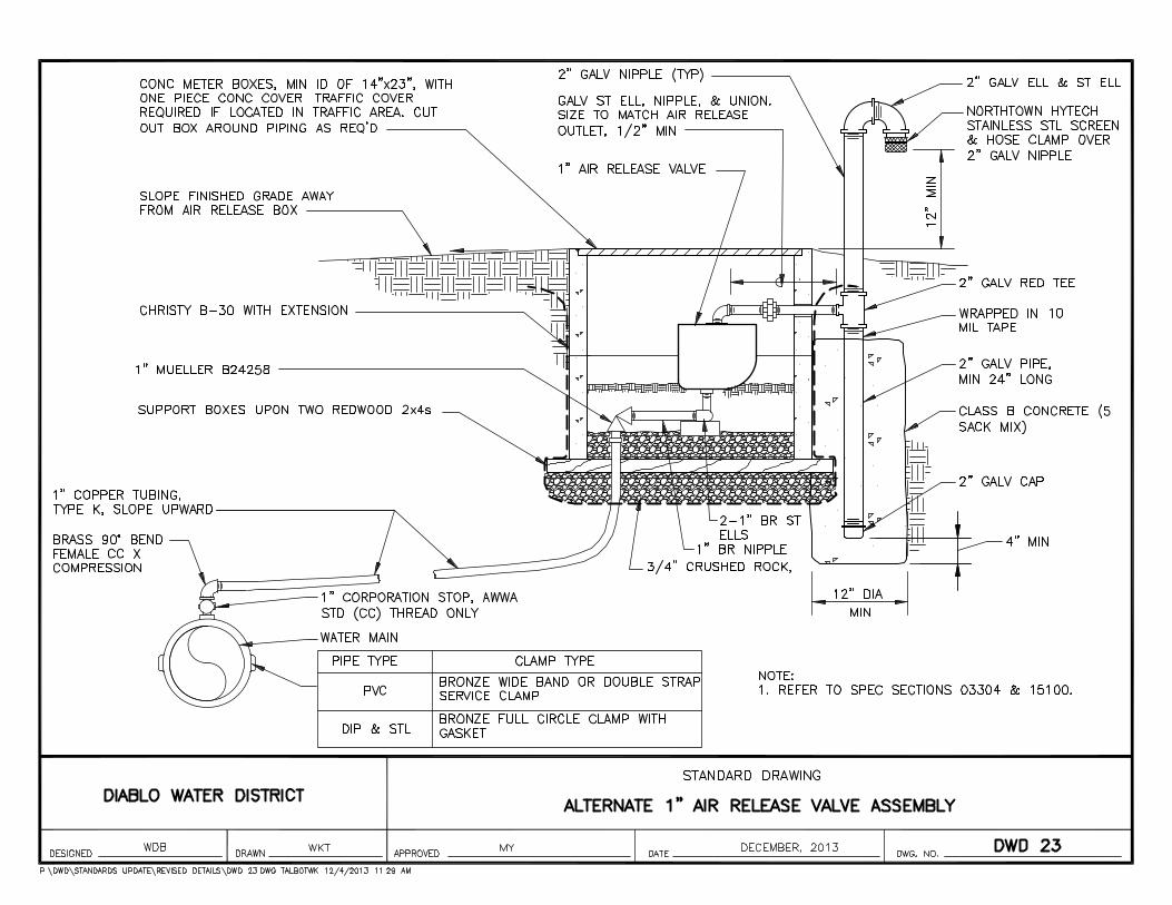
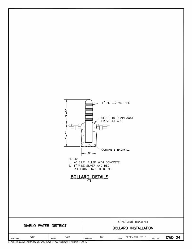

7. Cathodic Protection
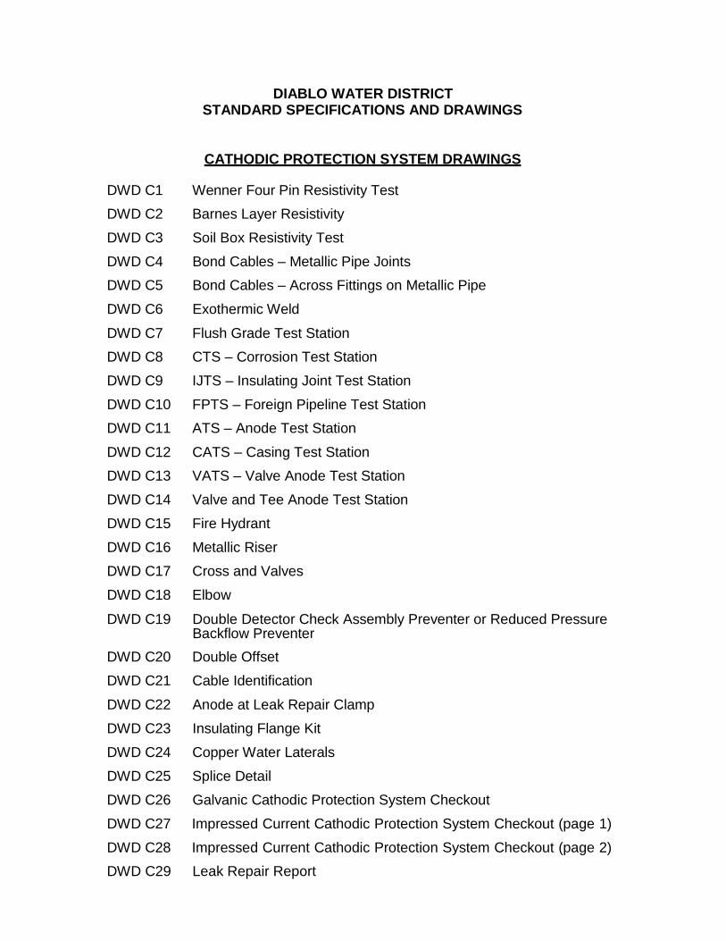
DIABLO WATER DISTRICT STANDARD SPECIFICATIONS AND DRAWINGS
CATHODIC PROTECTION SYSTEM DRAWINGS
DWD C1 Wenner Four Pin Resistivity Test
DWD C2 Barnes Layer Resistivity
DWD C3 Soil Box Resistivity Test
DWD C4 Bond Cables – Metallic Pipe Joints
DWD C5 Bond Cables – Across Fittings on Metallic Pipe
DWD C6 Exothermic Weld
DWD C7 Flush Grade Test Station
DWD C8 CTS – Corrosion Test Station
DWD C9 IJTS – Insulating Joint Test Station
DWD C10 FPTS – Foreign Pipeline Test Station
DWD C11 ATS – Anode Test Station
DWD C12 CATS – Casing Test Station
DWD C13 VATS – Valve Anode Test Station
DWD C14 Valve and Tee Anode Test Station
DWD C15 Fire Hydrant
DWD C16 Metallic Riser
DWD C17 Cross and Valves
DWD C18 Elbow
DWD C19 Double Detector Check Assembly Preventer or Reduced Pressure Backflow Preventer
DWD C20 Double Offset
DWD C21 Cable Identification
DWD C22 Anode at Leak Repair Clamp
DWD C23 Insulating Flange Kit
DWD C24 Copper Water Laterals
DWD C25 Splice Detail
DWD C26 Galvanic Cathodic Protection System Checkout
DWD C27 Impressed Current Cathodic Protection System Checkout (page 1)
DWD C28 Impressed Current Cathodic Protection System Checkout (page 2)
DWD C29 Leak Repair Report

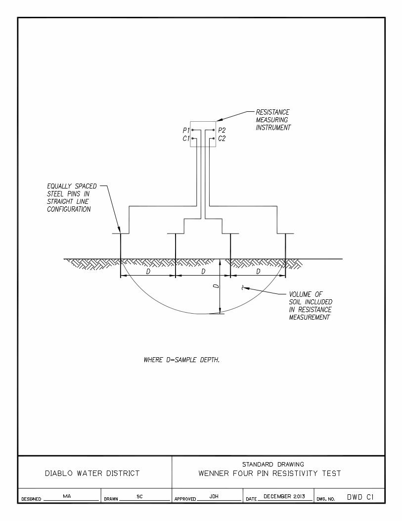
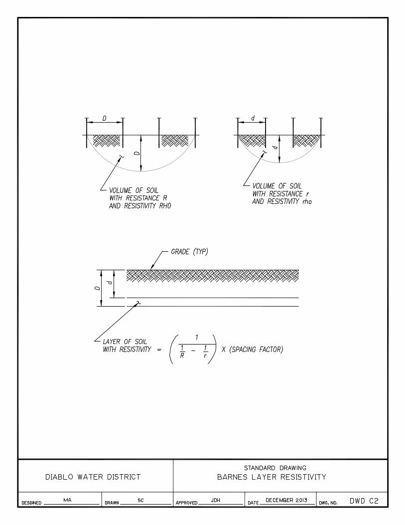
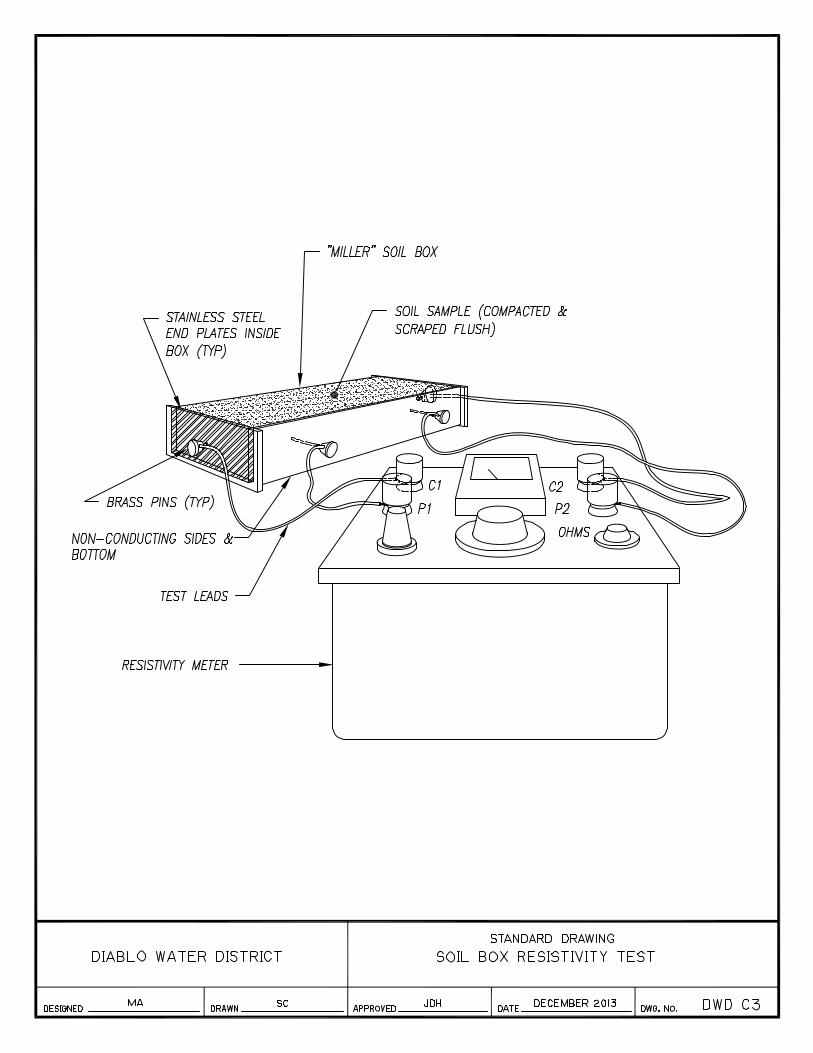
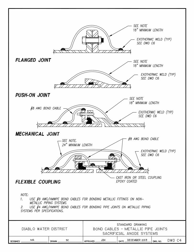
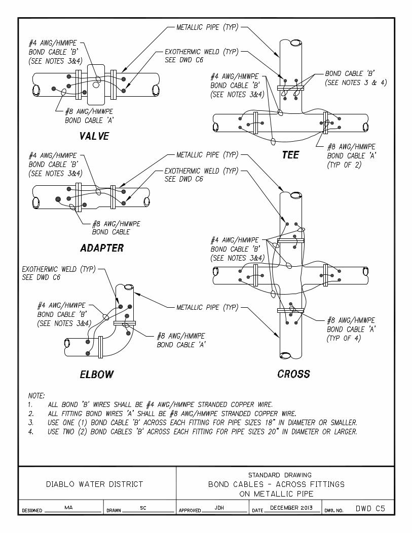
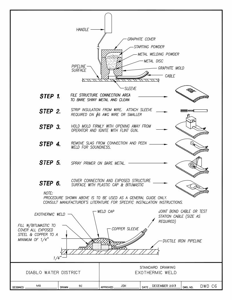
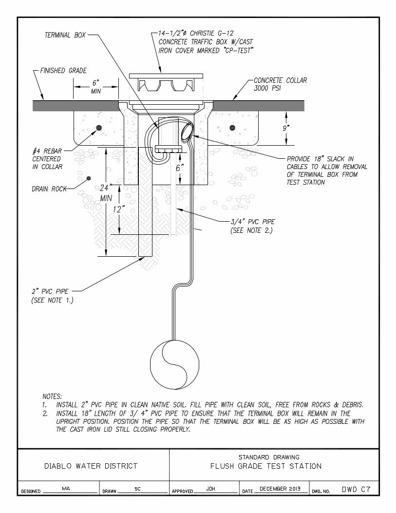
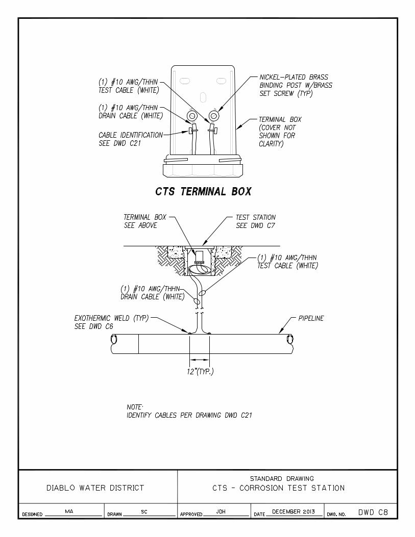
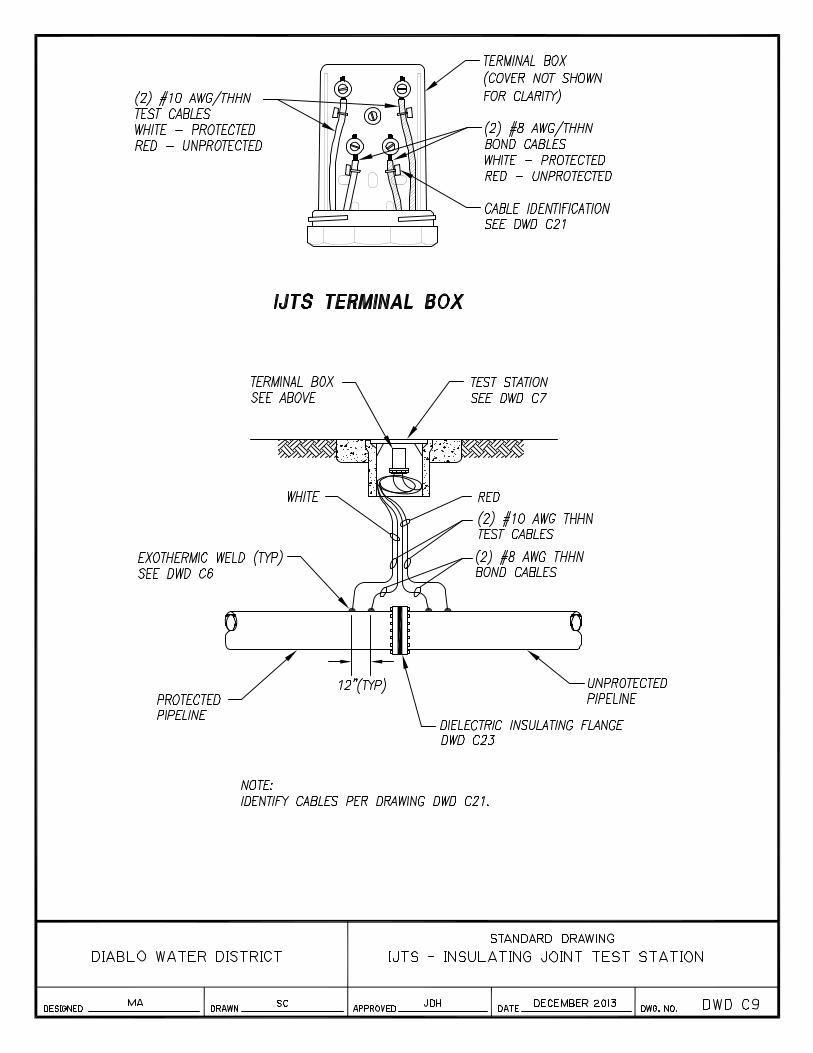
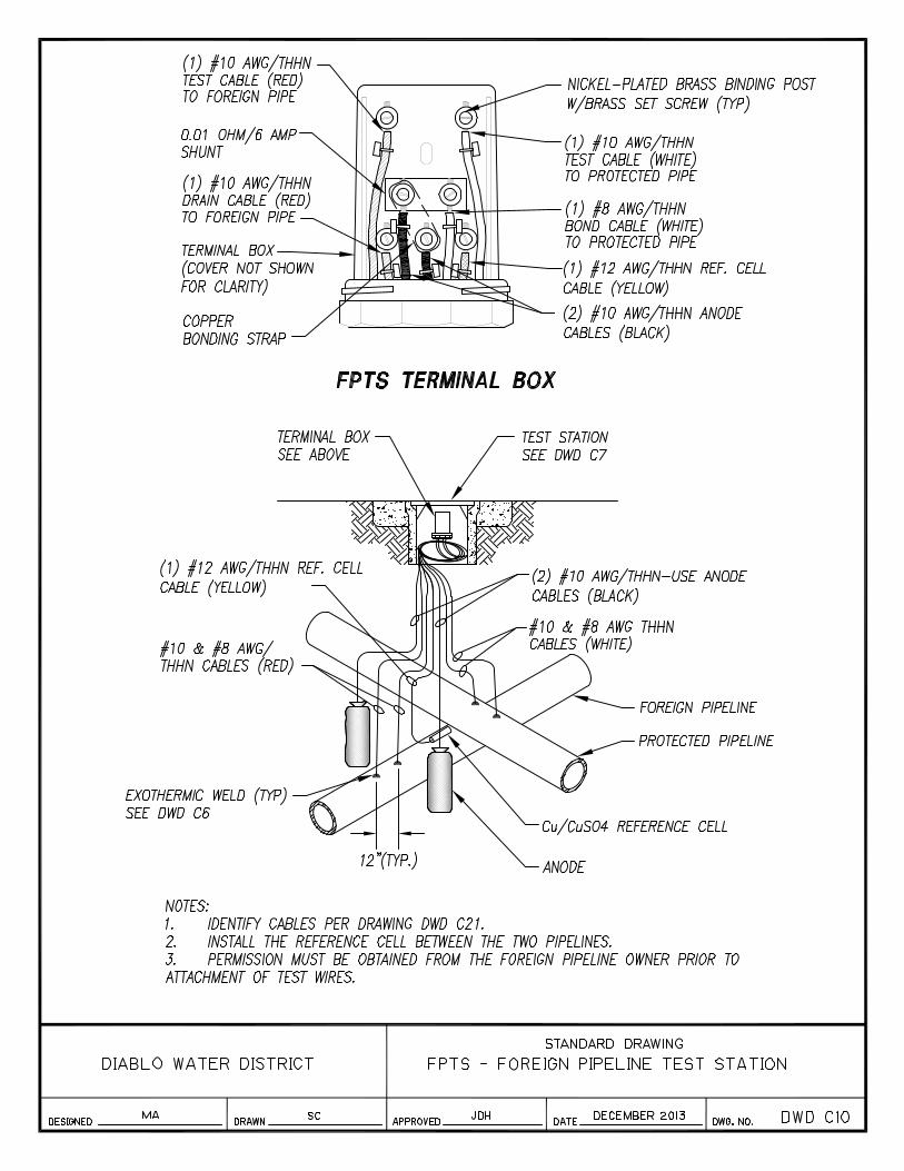
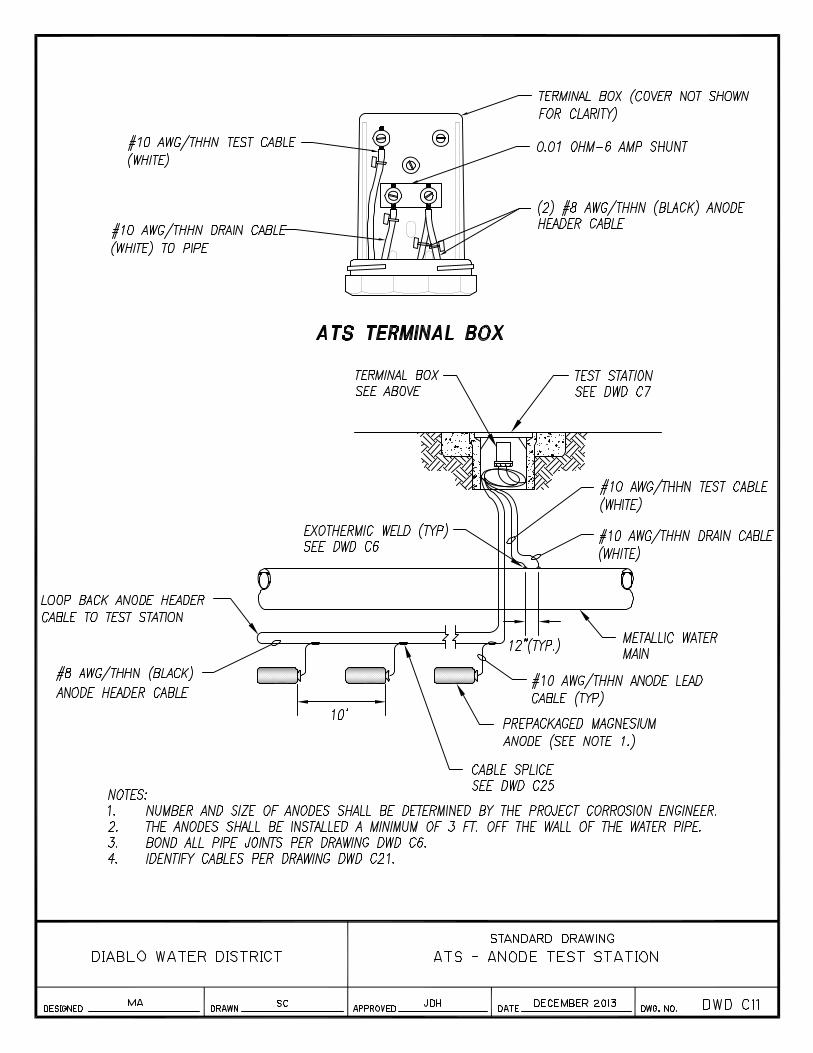
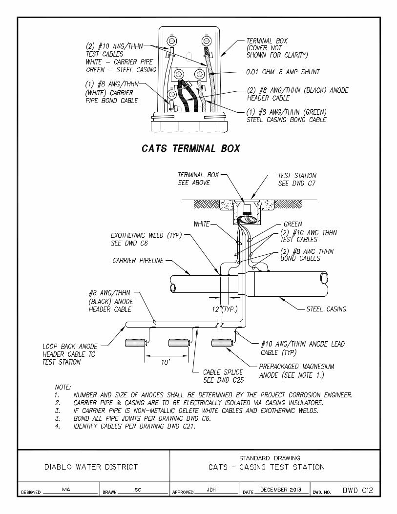
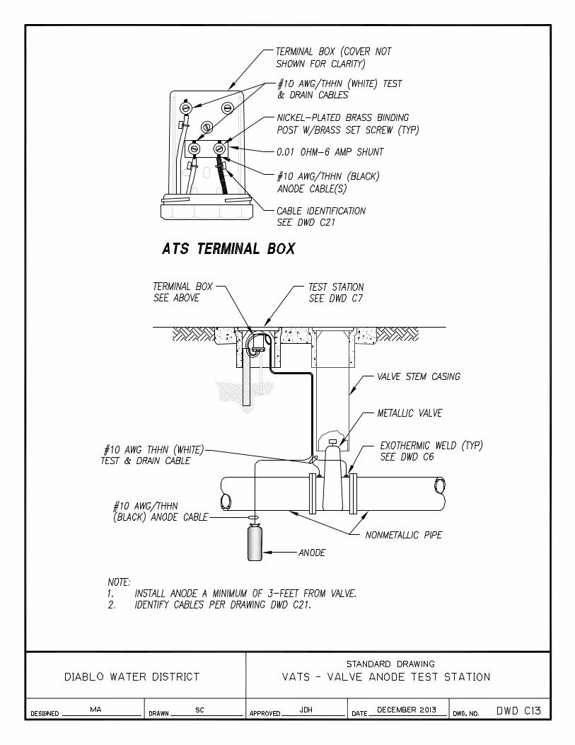
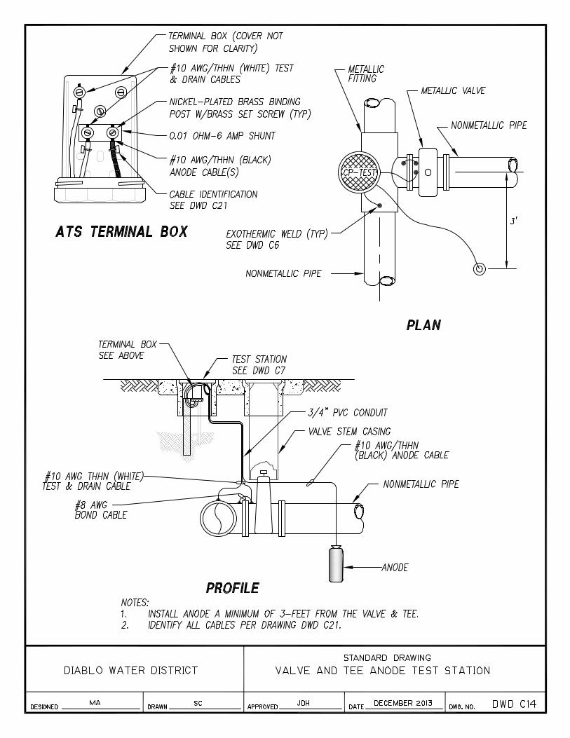
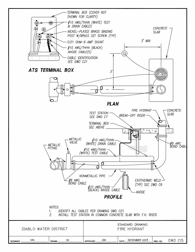
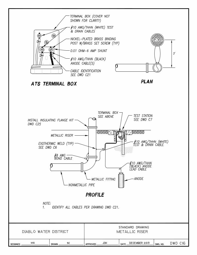
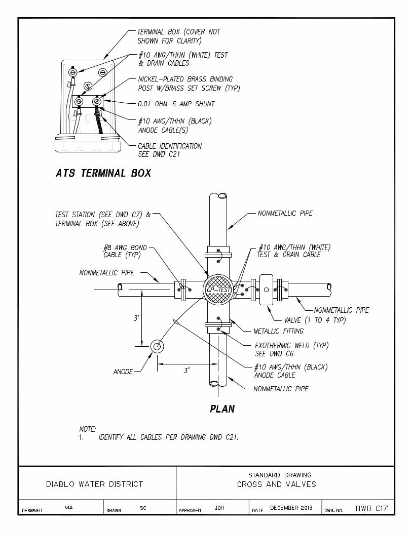
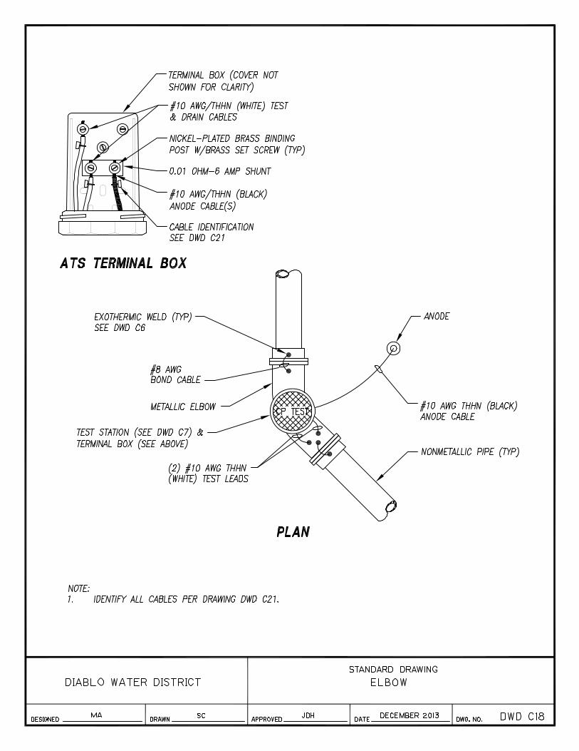
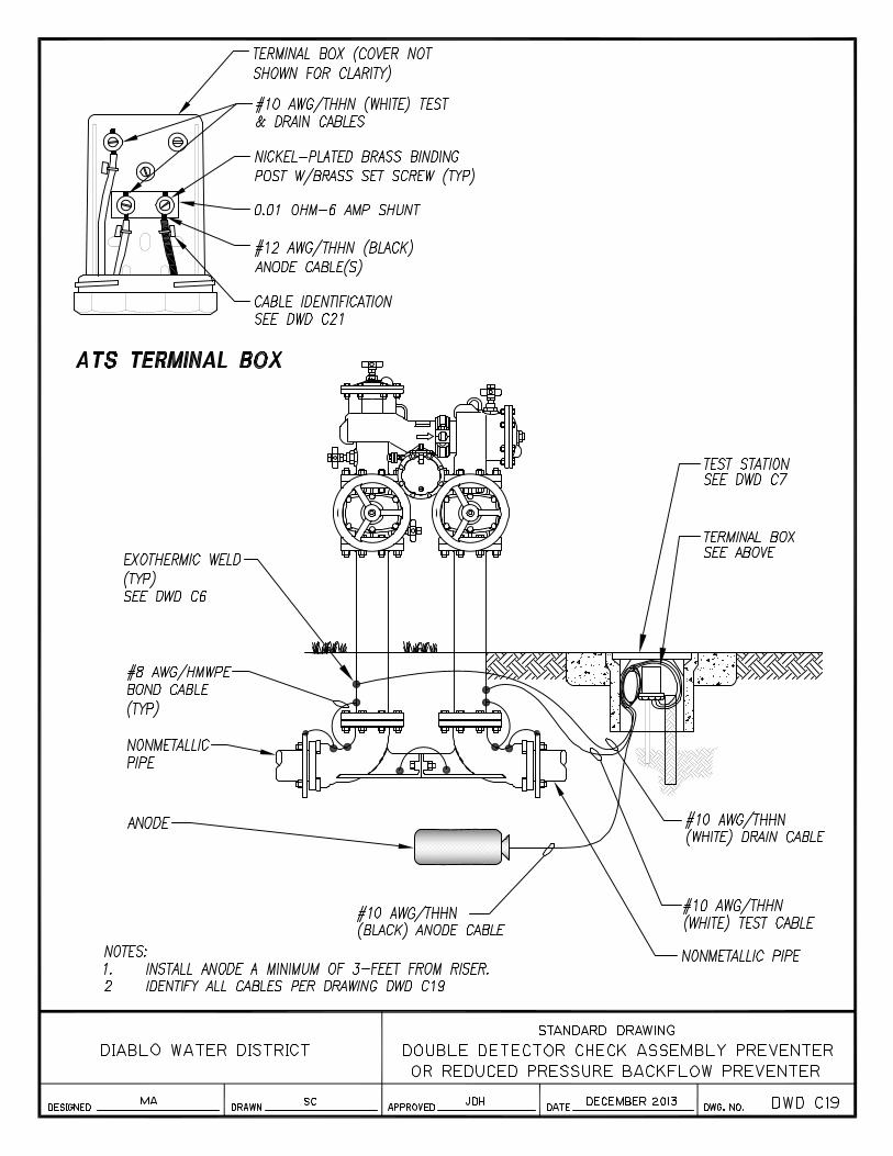
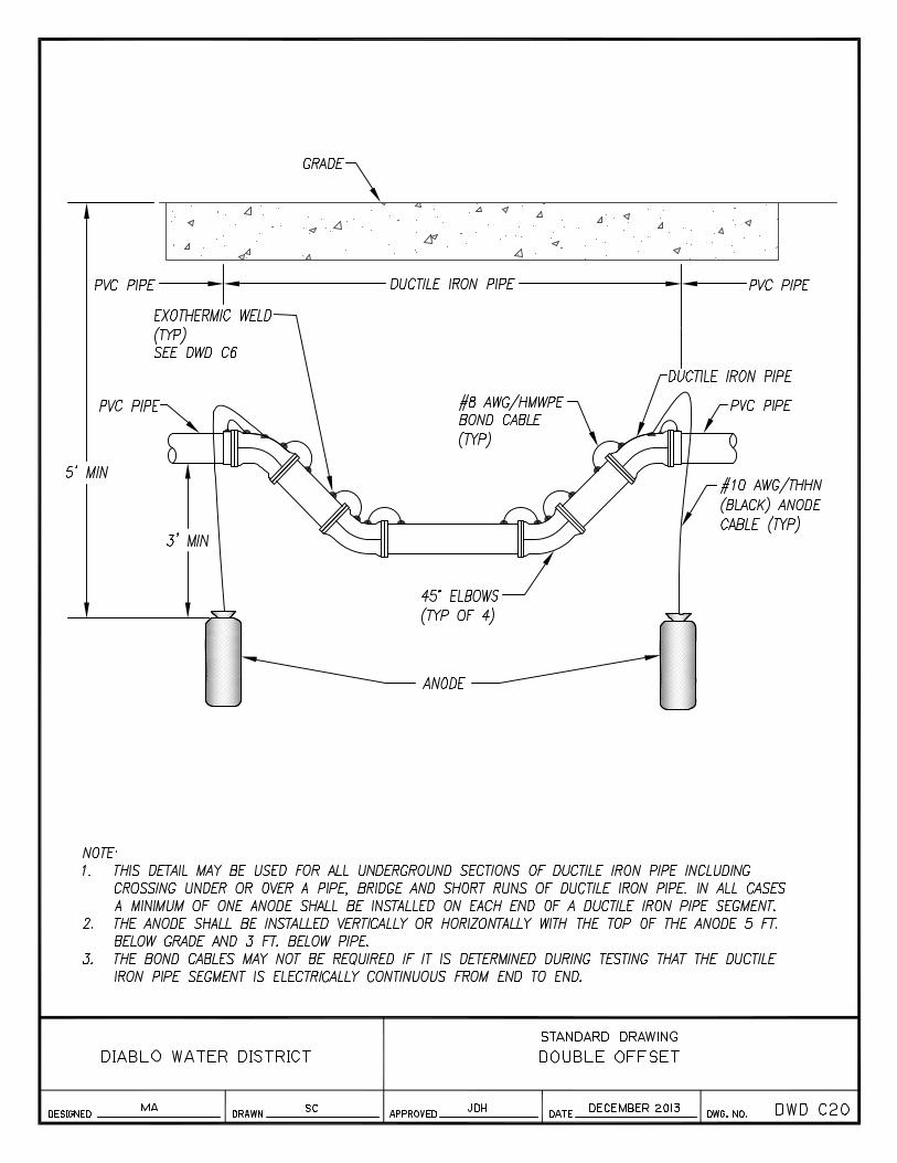
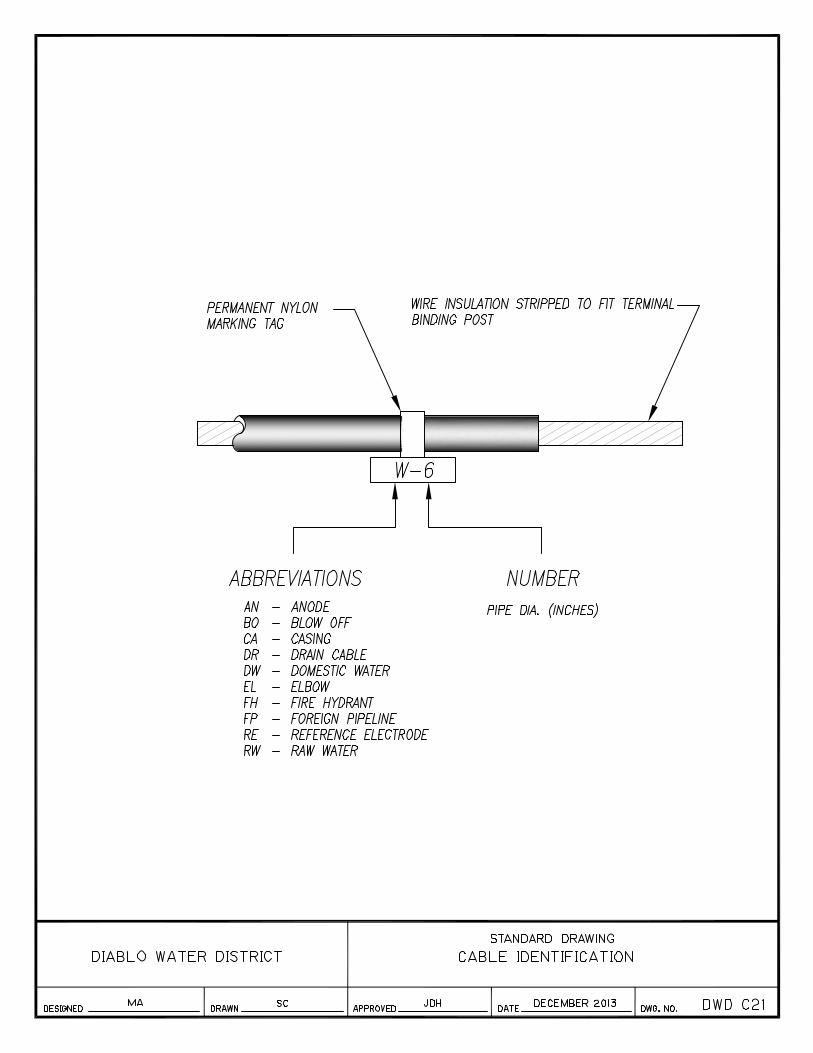
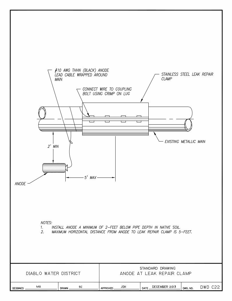
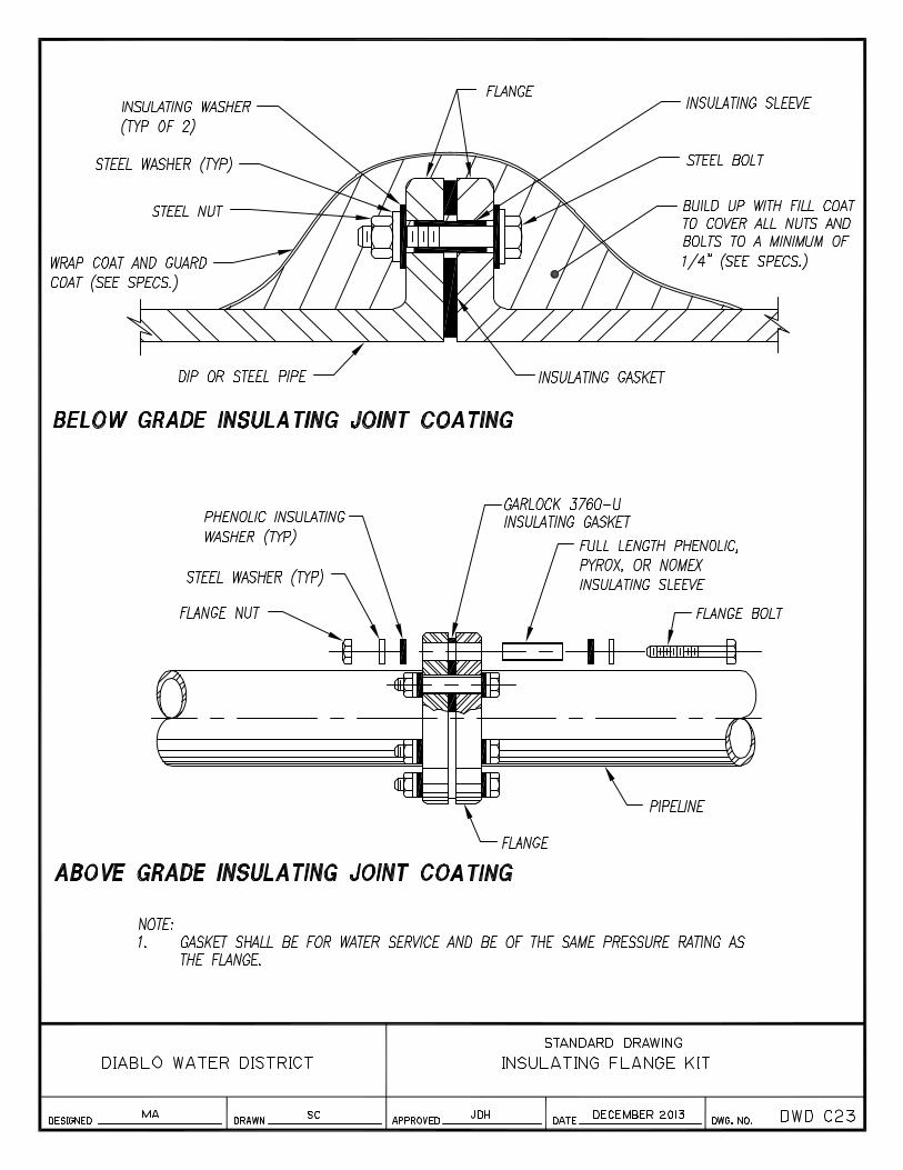

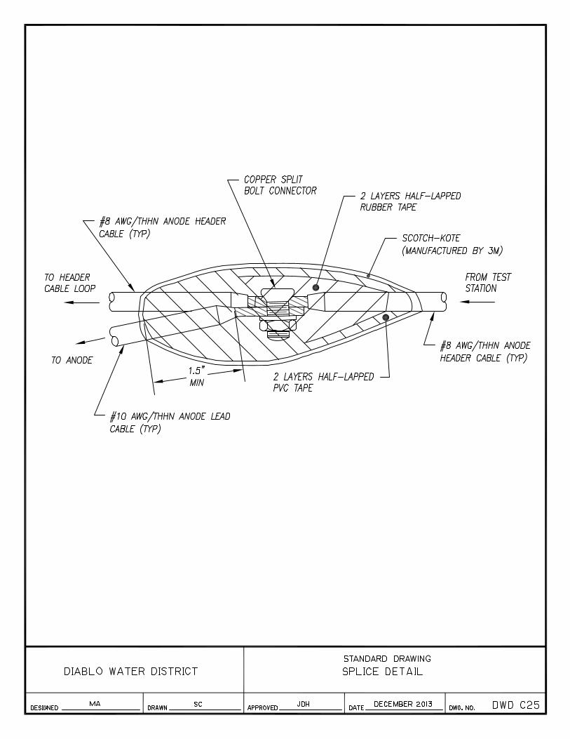
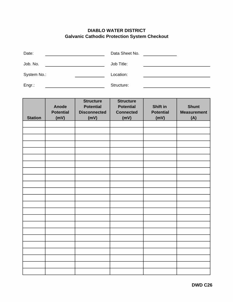
Date: Data Sheet No.
Job. No. Job Title:
System No.: Location:
Engr.: Structure:
StructureAnode Potential Shift in Shunt
Potential Connected Potential MeasurementStation (mV) (mV) (mV) (A)
Disconnected(mV)
DIABLO WATER DISTRICTGalvanic Cathodic Protection System Checkout
StructurePotential
DWD C26

Date: Data Sheet No.
Job. No. Job Title:
Rectifier No. Location:
Engr.: Structure:
RECTIFIER DATA:
Input (AC): Volts: Amps:
Phase: Cycles:
Rated Output (DC): Volts: Amps:
Coarse: Fine:Date Energized:
DC OUTPUT:
By Panel Meter: Volts: Amps:
By Volt Meter: Volts: Amps:
Shunt Potential Measured:
Shunt Rating: Amps: per mV:
Current Calculated: Amps
ANODE DATA:
Anode Description: No.
Size: X Long Lbs.
Shunt Rating: mV
Reading(mV)
DIABLO WATER DISTRICTImpressed Current Cathodic Protection System Checkout
Amps AmpsReading(mV)
AnodeNo.
AnodeNo.
DWD C27
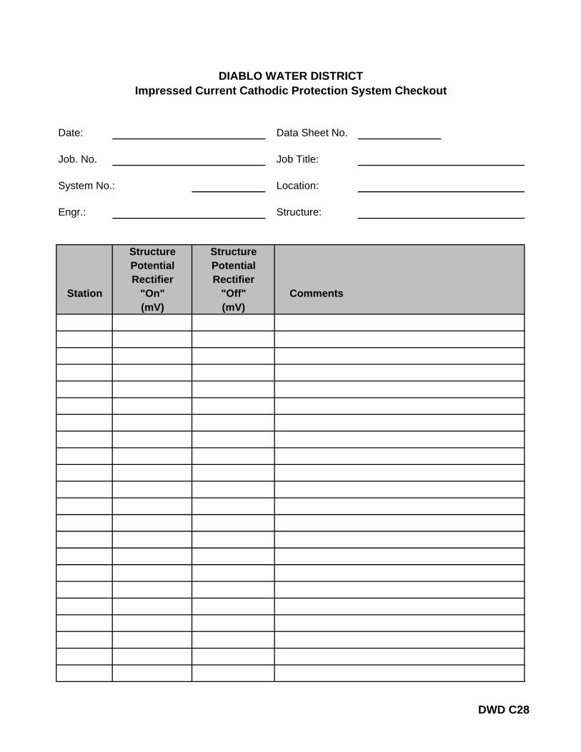
Date: Data Sheet No.
Job. No. Job Title:
System No.: Location:
Engr.: Structure:
StructurePotentialRectifier
Station "On" Comments(mV) (mV)
Rectifier"Off"
DIABLO WATER DISTRICTImpressed Current Cathodic Protection System Checkout
StructurePotential
DWD C28
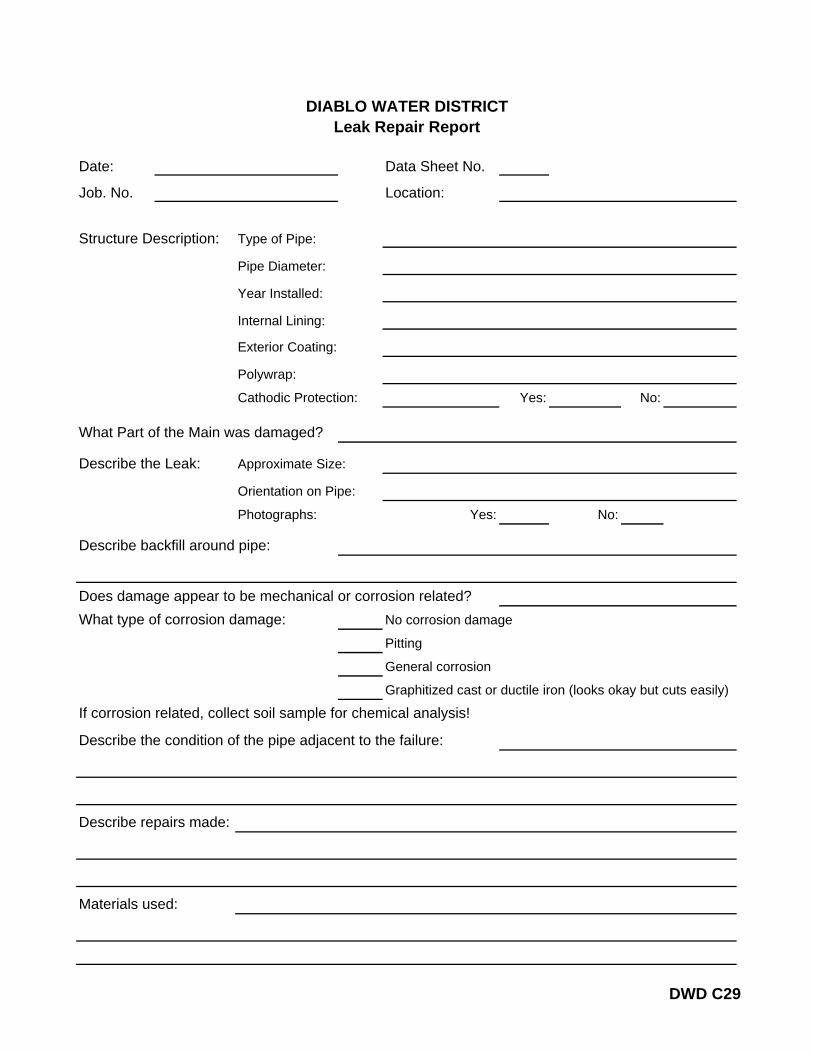
Date: Data Sheet No.
Job. No. Location:
Structure Description: Type of Pipe:
Pipe Diameter:
Year Installed:
Internal Lining:
Exterior Coating:
Polywrap:
Cathodic Protection: Yes: No:
What Part of the Main was damaged?
Describe the Leak: Approximate Size:
Orientation on Pipe:
Photographs: Yes: No:
Describe backfill around pipe:
Does damage appear to be mechanical or corrosion related? What type of corrosion damage: No corrosion damage
Pitting
General corrosion
Graphitized cast or ductile iron (looks okay but cuts easily)
If corrosion related, collect soil sample for chemical analysis!
Describe the condition of the pipe adjacent to the failure:
Describe repairs made:
Materials used:
DIABLO WATER DISTRICTLeak Repair Report
DWD C29
8. Design Requirements
DIABLO WATER DISTRICT STANDARD SPECIFICATIONS AND DRAWINGS
DESIGN REQUIREMENTS
I. Subdivision Water System Design Requirements and Plan Review Checklist
II. DWD General Water Notes
III. Cathodic Protection Number Format for Subdivision Plans
IV. DHS Criteria for Separation of Water Mains and Sanitary Sewers (Revised
October 16, 2003) V. System Pressures – Requirements for Individual Pressure Reducing Valves
on Customer Services
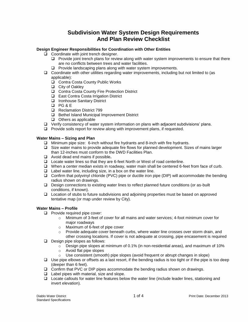
Diablo Water District 1 of 4 Print Date: December 2013
Standard Specifications
Subdivision Water System Design Requirements And Plan Review Checklist
Design Engineer Responsibilities for Coordination with Other Entities
Coordinate with joint trench designer. Provide joint trench plans for review along with water system improvements to ensure that there
are no conflicts between trees and water facilities. Provide landscaping plans along with water system improvements.
Coordinate with other utilities regarding water improvements, including but not limited to (as applicable): Contra Costa County Public Works City of Oakley Contra Costa County Fire Protection District East Contra Costa Irrigation District Ironhouse Sanitary District PG & E Reclamation District 799 Bethel Island Municipal Improvement District Others as applicable
Verify consistency of water system information on plans with adjacent subdivisions’ plans. Provide soils report for review along with improvement plans, if requested.
Water Mains – Sizing and Plan
Minimum pipe size: 6-inch without fire hydrants and 8-inch with fire hydrants. Size water mains to provide adequate fire flows for planned development. Sizes of mains larger
than 12-inches must conform to the DWD Facilities Plan. Avoid dead end mains if possible. Locate water lines so that they are 6-feet North or West of road centerline. When a center median exists in roadway, water main shall be centered 6-feet from face of curb. Label water line, including size, in a box on the water line. Confirm that polyvinyl chloride (PVC) pipe or ductile iron pipe (DIP) will accommodate the bending
radius shown on drawings. Design connections to existing water lines to reflect planned future conditions (or as-built
conditions, if known). Location of stubs to future subdivisions and adjoining properties must be based on approved
tentative map (or map under review by City). Water Mains – Profile
Provide required pipe cover: o Minimum of 3-feet of cover for all mains and water services; 4-foot minimum cover for
major roadways o Maximum of 6-feet of pipe cover o Provide adequate cover beneath curbs, where water line crosses over storm drain, and
other crossing locations. If cover is not adequate at crossing, pipe encasement is required Design pipe slopes as follows:
o Design pipe slopes at minimum of 0.1% (in non-residential areas), and maximum of 10% o Avoid flat pipe slopes o Use consistent (smooth) pipe slopes (avoid frequent or abrupt changes in slope)
Use pipe elbows or offsets as a last resort, if the bending radius is too tight or if the pipe is too deep (deeper than 6 feet).
Confirm that PVC or DIP pipes accommodate the bending radius shown on drawings. Label pipes with material, size and slope. Locate callouts for water line features below the water line (include leader lines, stationing and
invert elevation).
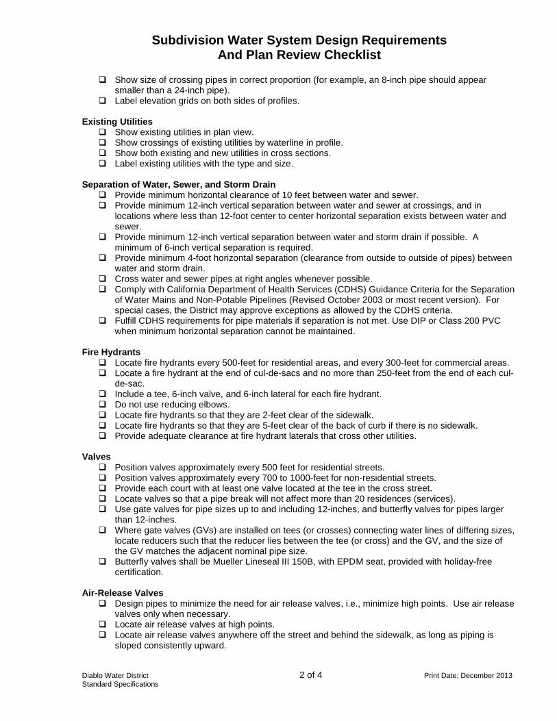
Subdivision Water System Design Requirements And Plan Review Checklist
Diablo Water District 2 of 4 Print Date: December 2013
Standard Specifications
Show size of crossing pipes in correct proportion (for example, an 8-inch pipe should appear smaller than a 24-inch pipe).
Label elevation grids on both sides of profiles. Existing Utilities
Show existing utilities in plan view. Show crossings of existing utilities by waterline in profile. Show both existing and new utilities in cross sections. Label existing utilities with the type and size.
Separation of Water, Sewer, and Storm Drain
Provide minimum horizontal clearance of 10 feet between water and sewer. Provide minimum 12-inch vertical separation between water and sewer at crossings, and in
locations where less than 12-foot center to center horizontal separation exists between water and sewer.
Provide minimum 12-inch vertical separation between water and storm drain if possible. A minimum of 6-inch vertical separation is required.
Provide minimum 4-foot horizontal separation (clearance from outside to outside of pipes) between water and storm drain.
Cross water and sewer pipes at right angles whenever possible. Comply with California Department of Health Services (CDHS) Guidance Criteria for the Separation
of Water Mains and Non-Potable Pipelines (Revised October 2003 or most recent version). For special cases, the District may approve exceptions as allowed by the CDHS criteria.
Fulfill CDHS requirements for pipe materials if separation is not met. Use DIP or Class 200 PVC when minimum horizontal separation cannot be maintained.
Fire Hydrants Locate fire hydrants every 500-feet for residential areas, and every 300-feet for commercial areas. Locate a fire hydrant at the end of cul-de-sacs and no more than 250-feet from the end of each cul-
de-sac. Include a tee, 6-inch valve, and 6-inch lateral for each fire hydrant. Do not use reducing elbows. Locate fire hydrants so that they are 2-feet clear of the sidewalk. Locate fire hydrants so that they are 5-feet clear of the back of curb if there is no sidewalk. Provide adequate clearance at fire hydrant laterals that cross other utilities.
Valves
Position valves approximately every 500 feet for residential streets. Position valves approximately every 700 to 1000-feet for non-residential streets. Provide each court with at least one valve located at the tee in the cross street. Locate valves so that a pipe break will not affect more than 20 residences (services). Use gate valves for pipe sizes up to and including 12-inches, and butterfly valves for pipes larger
than 12-inches. Where gate valves (GVs) are installed on tees (or crosses) connecting water lines of differing sizes,
locate reducers such that the reducer lies between the tee (or cross) and the GV, and the size of the GV matches the adjacent nominal pipe size.
Butterfly valves shall be Mueller Lineseal III 150B, with EPDM seat, provided with holiday-free certification.
Air-Release Valves
Design pipes to minimize the need for air release valves, i.e., minimize high points. Use air release valves only when necessary.
Locate air release valves at high points. Locate air release valves anywhere off the street and behind the sidewalk, as long as piping is
sloped consistently upward.
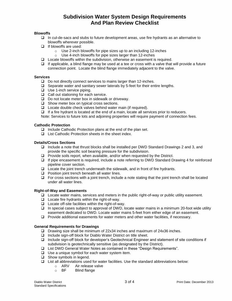
Subdivision Water System Design Requirements And Plan Review Checklist
Diablo Water District 3 of 4 Print Date: December 2013
Standard Specifications
Blowoffs In cul-de-sacs and stubs to future development areas, use fire hydrants as an alternative to
blowoffs wherever possible. If blowoffs are used:
o Use 2-inch blowoffs for pipe sizes up to an including 12-inches o Use 4-inch blowoffs for pipe sizes larger than 12-inches
Locate blowoffs within the subdivision, otherwise an easement is required. If applicable, a blind flange may be used at a tee or cross with a valve that will provide a future
connection point. Locate the blind flange immediately adjacent to the valve. Services
Do not directly connect services to mains larger than 12-inches. Separate water and sanitary sewer laterals by 5-feet for their entire lengths. Use 1-inch service piping. Call out stationing for each service. Do not locate meter box in sidewalk or driveway. Show meter box on typical cross sections. Locate double check valves behind water main (if required). If a fire hydrant is located at the end of a main, locate all services prior to reducers. Note: Services to future lots and adjoining properties will require payment of connection fees.
Cathodic Protection
Include Cathodic Protection plans at the end of the plan set. List Cathodic Protection sheets in the sheet index.
Details/Cross Sections
Include a note that thrust blocks shall be installed per DWD Standard Drawings 2 and 3, and provide the specific soil bearing pressure for the subdivision.
Provide soils report, when available, and/or when requested by the District. If pipe encasement is required, include a note referring to DWD Standard Drawing 4 for reinforced
pipeline cover section. Locate the joint trench underneath the sidewalk, and in front of fire hydrants. Position joint trench beneath all water lines. For cross sections with a joint trench, include a note stating that the joint trench shall be located
under all water lines. Right-of-Way and Easements
Locate water mains, services and meters in the public right-of-way or public utility easement. Locate fire hydrants within the right-of-way. Locate off-site facilities within the right-of-way. In special cases subject to approval of DWD, locate water mains in a minimum 20-foot wide utility
easement dedicated to DWD. Locate water mains 5-feet from either edge of an easement. Provide additional easements for water meters and other water facilities, if necessary.
General Requirements for Drawings
Drawing size shall be minimum of 22x34 inches and maximum of 24x36 inches. Include sign-off block for Diablo Water District on title sheet. Include sign-off block for developer’s Geotechnical Engineer and statement of site conditions if
subdivision is geotechnically sensitive (as designated by the District). List DWD General Water Notes as contained in these “Design Requirements”. Use a unique symbol for each water system item. Show symbols in legend. List all abbreviations used for water facilities. Use the standard abbreviations below:
o ARV Air release valve o BF Blind flange
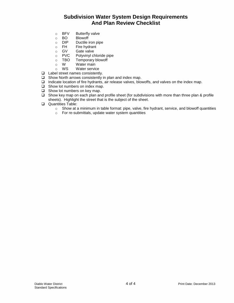
Subdivision Water System Design Requirements And Plan Review Checklist
Diablo Water District 4 of 4 Print Date: December 2013
Standard Specifications
o BFV Butterfly valve o BO Blowoff o DIP Ductile iron pipe o FH Fire hydrant o GV Gate valve o PVC Polyvinyl chloride pipe o TBO Temporary blowoff o W Water main o WS Water service
Label street names consistently. Show North arrows consistently in plan and index map. Indicate location of fire hydrants, air release valves, blowoffs, and valves on the index map. Show lot numbers on index map. Show lot numbers on key map. Show key map on each plan and profile sheet (for subdivisions with more than three plan & profile
sheets). Highlight the street that is the subject of the sheet. Quantities Table:
o Show at a minimum in table format: pipe, valve, fire hydrant, service, and blowoff quantities o For re-submittals, update water system quantities
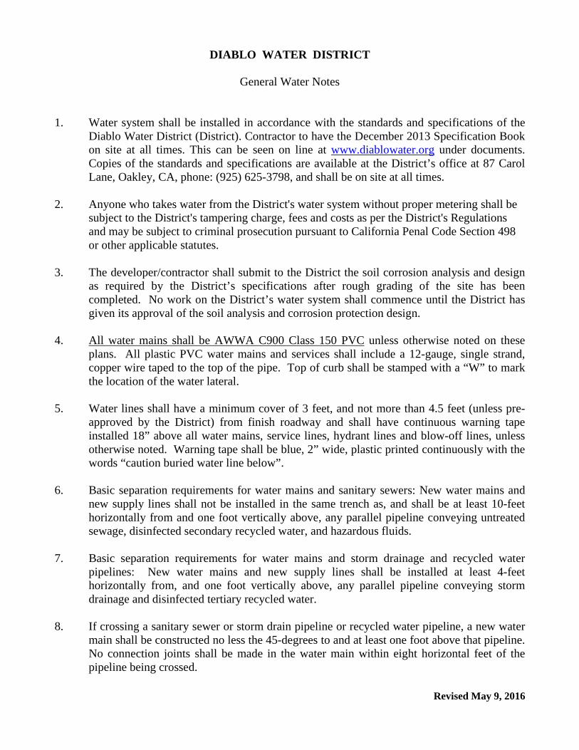
Revised May 9, 2016
DIABLO WATER DISTRICT
General Water Notes
1. Water system shall be installed in accordance with the standards and specifications of the Diablo Water District (District). Contractor to have the December 2013 Specification Book on site at all times. This can be seen on line at www.diablowater.org under documents. Copies of the standards and specifications are available at the District’s office at 87 Carol Lane, Oakley, CA, phone: (925) 625-3798, and shall be on site at all times.
2. Anyone who takes water from the District's water system without proper metering shall be
subject to the District's tampering charge, fees and costs as per the District's Regulations and may be subject to criminal prosecution pursuant to California Penal Code Section 498 or other applicable statutes.
3. The developer/contractor shall submit to the District the soil corrosion analysis and design
as required by the District’s specifications after rough grading of the site has been completed. No work on the District’s water system shall commence until the District has given its approval of the soil analysis and corrosion protection design.
4. All water mains shall be AWWA C900 Class 150 PVC unless otherwise noted on these
plans. All plastic PVC water mains and services shall include a 12-gauge, single strand, copper wire taped to the top of the pipe. Top of curb shall be stamped with a “W” to mark the location of the water lateral.
5. Water lines shall have a minimum cover of 3 feet, and not more than 4.5 feet (unless pre-
approved by the District) from finish roadway and shall have continuous warning tape installed 18” above all water mains, service lines, hydrant lines and blow-off lines, unless otherwise noted. Warning tape shall be blue, 2” wide, plastic printed continuously with the words “caution buried water line below”.
6. Basic separation requirements for water mains and sanitary sewers: New water mains and
new supply lines shall not be installed in the same trench as, and shall be at least 10-feet horizontally from and one foot vertically above, any parallel pipeline conveying untreated sewage, disinfected secondary recycled water, and hazardous fluids.
7. Basic separation requirements for water mains and storm drainage and recycled water pipelines: New water mains and new supply lines shall be installed at least 4-feet horizontally from, and one foot vertically above, any parallel pipeline conveying storm drainage and disinfected tertiary recycled water.
8. If crossing a sanitary sewer or storm drain pipeline or recycled water pipeline, a new water
main shall be constructed no less the 45-degrees to and at least one foot above that pipeline. No connection joints shall be made in the water main within eight horizontal feet of the pipeline being crossed.
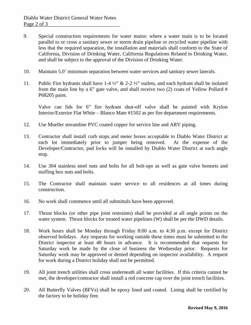
Diablo Water District General Water Notes Page 2 of 3
Revised May 9, 2016
9. Special construction requirements for water mains: where a water main is to be located parallel to or cross a sanitary sewer or storm drain pipeline or recycled water pipeline with less that the required separation, the installation and materials shall conform to the State of California, Division of Drinking Water, California Regulations Related to Drinking Water, and shall be subject to the approval of the Division of Drinking Water.
10. Maintain 5.0’ minimum separation between water services and sanitary sewer laterals. 11. Public Fire hydrants shall have 1-4 ½” & 2-2 ½” outlets, and each hydrant shall be isolated
from the main line by a 6” gate valve, and shall receive two (2) coats of Yellow Pollard # P68205 paint.
Valve can lids for 6” fire hydrant shut-off valve shall be painted with Krylon Interior/Exterior Flat White – Blanco Mate #1502 as per fire department requirements.
12. Use Mueller streamline PVC coated copper for service line and ARV piping. 13. Contractor shall install curb stops and meter boxes acceptable to Diablo Water District at
each lot immediately prior to jumper being removed. At the expense of the Developer/Contractor, pad locks will be installed by Diablo Water District at each angle stop.
14. Use 304 stainless steel nuts and bolts for all bolt-ups as well as gate valve bonnets and
stuffing box nuts and bolts. 15. The Contractor shall maintain water service to all residences at all times during
construction. 16. No work shall commence until all submittals have been approved. 17. Thrust blocks (or other pipe joint restraints) shall be provided at all angle points on the
water system. Thrust blocks for treated water pipelines (W) shall be per the DWD details. 18. Work hours shall be Monday through Friday 8:00 a.m. to 4:30 p.m. except for District
observed holidays. Any requests for working outside these times must be submitted to the District inspector at least 48 hours in advance. It is recommended that requests for Saturday work be made by the close of business the Wednesday prior. Requests for Saturday work may be approved or denied depending on inspector availability. A request for work during a District holiday shall not be permitted.
19. All joint trench utilities shall cross underneath all water facilities. If this criteria cannot be
met, the developer/contractor shall install a red concrete cap over the joint trench facilities. 20. All Butterfly Valves (BFVs) shall be epoxy lined and coated. Lining shall be certified by
the factory to be holiday free.

Diablo Water District General Water Notes Page 3 of 3
Revised May 9, 2016
21. All hot taps shall be performed by Tap Master, Inc. of Concord, California, phone: 925-
439-7975. Tapping sleeve shall be stainless steel type JCM 432, no equal. 22. No trees shall be planted within 10’ of any water mains, fire services, or fire hydrant
laterals. Measurement shall be taken as the clear distance between the root ball and water main.
23. All locator wires shall be tested and test results shall be included in the Cathodic Protection Test Report.
24. All water meters shall be provided with a 520M-FlexNet MTX Unit. Meter boxes for
meters less than 1-1/2 inch in size shall have Christy B12P001-F (FlexNet) lids. All meter box lids shall have drilled holes for FlexNet 520M Units.
25. Water Meters 5/8” in size shall be Sensus 5/8” x 3/4” iPERL, 1 cubic foot, labeled 5/8” x
3/4”.
Water Meters 1” in size shall be Sensus 1” iPERL, 1 cubic foot.
Water meters 1-1/2” through 6” in size shall be Sensus OMNI, Long Length C2, 1 cubic foot. Size shall be selected by applicant so as not to exceed published “Operating Range” of C2 meter.
26. JDH Corrosion Consultants, Inc., 1100 Willow Pass Court, Concord, CA, 925-927-6630, shall conduct all final cathodic protection test reports at the expense of the developer/contractor.
27. Install a ball shut-off valve and box on customer’s side after backflow device for new
construction as required by the City of Oakley’s specifications. 28. The developer/contractor shall provide the Global Positioning System (GPS) coordinates of
all buried fittings (excluding saddles and corporation stops) and all above ground facilities as determined by the District in a shapefile data format as defined by ESRI. GPS coordinates of existing water facilities that are exposed during any construction activity shall also be provided. All GPS coordinates shall be to within an accuracy of ten (10) centimeters and shall include Latitude, Longitude and Elevation.
29. The Contractor shall rechlorinate and retest any lines that do not pass the first or subsequent
round of bacteriological testing or as directed by Diablo Water District.

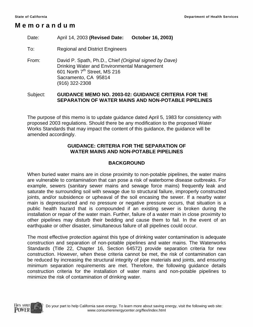
State of California Department of Health Services
M e m o r a n d u m
Date: April 14, 2003 (Revised Date: October 16, 2003) To: Regional and District Engineers From: David P. Spath, Ph.D., Chief (Original signed by Dave) Drinking Water and Environmental Management
601 North 7th Street, MS 216 Sacramento, CA 95814 (916) 322-2308
Subject: GUIDANCE MEMO NO. 2003-02: GUIDANCE CRITERIA FOR THE SEPARATION OF WATER MAINS AND NON-POTABLE PIPELINES
The purpose of this memo is to update guidance dated April 5, 1983 for consistency with proposed 2003 regulations. Should there be any modification to the proposed Water Works Standards that may impact the content of this guidance, the guidance will be amended accordingly.
GUIDANCE: CRITERIA FOR THE SEPARATION OF WATER MAINS AND NON-POTABLE PIPELINES
BACKGROUND
When buried water mains are in close proximity to non-potable pipelines, the water mains are vulnerable to contamination that can pose a risk of waterborne disease outbreaks. For example, sewers (sanitary sewer mains and sewage force mains) frequently leak and saturate the surrounding soil with sewage due to structural failure, improperly constructed joints, and/or subsidence or upheaval of the soil encasing the sewer. If a nearby water main is depressurized and no pressure or negative pressure occurs, that situation is a public health hazard that is compounded if an existing sewer is broken during the installation or repair of the water main. Further, failure of a water main in close proximity to other pipelines may disturb their bedding and cause them to fail. In the event of an earthquake or other disaster, simultaneous failure of all pipelines could occur. The most effective protection against this type of drinking water contamination is adequate construction and separation of non-potable pipelines and water mains. The Waterworks Standards (Title 22, Chapter 16, Section 64572) provide separation criteria for new construction. However, when these criteria cannot be met, the risk of contamination can be reduced by increasing the structural integrity of pipe materials and joints, and ensuring minimum separation requirements are met. Therefore, the following guidance details construction criteria for the installation of water mains and non-potable pipelines to minimize the risk of contamination of drinking water.
Do your part to help California save energy. To learn more about saving energy, visit the following web site: www.consumerenergycenter.org/flex/index.html
April 14, 2003 (Revised: October 16, 2003) Page 2 of 11 Guidance Memo No. 2003-02
DEFINITIONS
COMPRESSION JOINT - A push-on joint that seals by means of the compression of a rubber ring or gasket between the pipe and a bell or coupling.
CONTINUOUS SLEEVE - A protective tube of high-density-polyethylene (HDPE)
pipe with heat fusion joints or other non-potable metallic casing without joints into which a pipe is inserted.
DISINFECTED TERTIARY RECYCLED WATER - Wastewater that has been
filtered and subsequently disinfected in accordance with Section 60301.230, Chapter 3 (Water Recycling Criteria), Title 22, California Code of Regulations.
HOUSE LATERAL - A sewer line connecting the building drain and the sanitary
sewer main serving the street. SUPPLY LINE - Pipelines conveying raw water to be treated for drinking purposes
in accordance with Section 64572 ©, proposed Water Works Standards. WATER MAIN – Means any pipeline, except for user service lines, within the
distribution system in accordance with Section 64551.70, proposed Water Works Standards.
RATED WORKING WATER PRESSURE - A pipe classification system based on
internal working pressure of the fluid in the pipe, type of pipe material, and the thickness of the pipe wall.
SANITARY SEWER MAIN - A gravity sewer conveying untreated municipal
wastewater. SEWAGE FORCE MAIN - A pressurized sewer conveying untreated municipal
wastewater.
APPLICABILITY Note that the construction criteria presented in this document apply to house laterals that cross above a water main, but not to those house laterals that cross below a water main. Water mains or non-potable pipelines that are 24-inches in diameter or larger may pose a higher degree of public health concern because of the large volumes of flow involved. Therefore, installation of water mains or non-potable pipelines 24-inches in diameter or larger should be reviewed and approved in writing by the Department on a case-by-case basis prior to construction. In no case, should water mains and non-potable pipelines conveying sewage or other liquids be installed in the same trench.
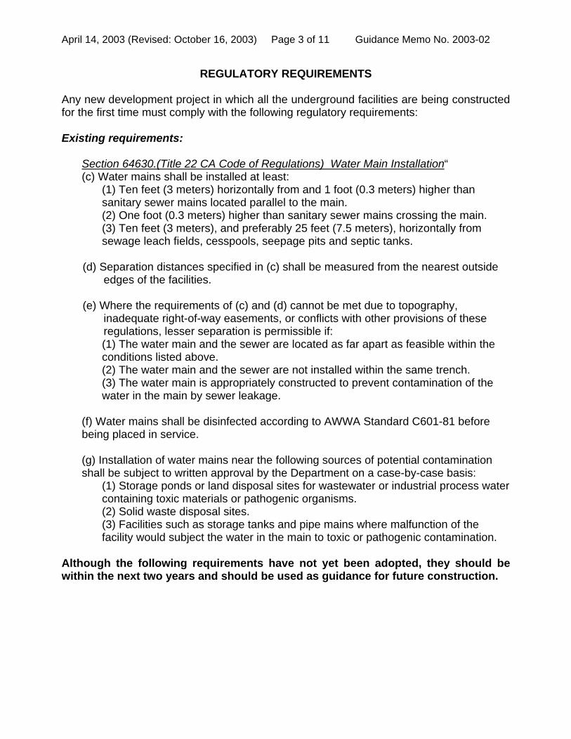
April 14, 2003 (Revised: October 16, 2003) Page 3 of 11 Guidance Memo No. 2003-02
REGULATORY REQUIREMENTS
Any new development project in which all the underground facilities are being constructed for the first time must comply with the following regulatory requirements: Existing requirements:
Section 64630.(Title 22 CA Code of Regulations) Water Main Installation“ (c) Water mains shall be installed at least:
(1) Ten feet (3 meters) horizontally from and 1 foot (0.3 meters) higher than sanitary sewer mains located parallel to the main. (2) One foot (0.3 meters) higher than sanitary sewer mains crossing the main. (3) Ten feet (3 meters), and preferably 25 feet (7.5 meters), horizontally from sewage leach fields, cesspools, seepage pits and septic tanks.
(d) Separation distances specified in (c) shall be measured from the nearest outside edges of the facilities.
(e) Where the requirements of (c) and (d) cannot be met due to topography,
inadequate right-of-way easements, or conflicts with other provisions of these regulations, lesser separation is permissible if: (1) The water main and the sewer are located as far apart as feasible within the conditions listed above. (2) The water main and the sewer are not installed within the same trench. (3) The water main is appropriately constructed to prevent contamination of the water in the main by sewer leakage.
(f) Water mains shall be disinfected according to AWWA Standard C601-81 before being placed in service. (g) Installation of water mains near the following sources of potential contamination shall be subject to written approval by the Department on a case-by-case basis:
(1) Storage ponds or land disposal sites for wastewater or industrial process water containing toxic materials or pathogenic organisms. (2) Solid waste disposal sites. (3) Facilities such as storage tanks and pipe mains where malfunction of the facility would subject the water in the main to toxic or pathogenic contamination.
Although the following requirements have not yet been adopted, they should be within the next two years and should be used as guidance for future construction.

April 14, 2003 (Revised: October 16, 2003) Page 4 of 11 Guidance Memo No. 2003-02
Proposed requirements as of the date of this document: Section 64572. Water Main Separation
(a) New water mains and new supply lines shall not be installed in the same trench as, and shall be at least 10 feet horizontally from, and one foot vertically above, any parallel pipeline conveying:
(1) Untreated sewage, (2) Primary or secondary treated sewage, (3) Disinfected secondary-2.2 recycled water (defined in section 60301.220), (4) Disinfected secondary-23 recycled water (defined in section 60301.225), and (5) Hazardous fluids such as fuels, industrial wastes, and wastewater sludge.
(b) New water mains and new supply lines shall be installed at least 4 feet horizontally
from, and one foot vertically above, any parallel pipeline conveying: (1) Disinfected tertiary recycled water (defined in section 60301.230), and (2) Storm drainage.
(c) New supply lines conveying raw water to be treated for drinking purposes shall be
installed at least 4 feet horizontally from, and one foot vertically below, any water main. (d) If crossing a pipeline conveying a fluid listed in subsection (a) or (b), a new water
main shall be constructed perpendicular to and at least one foot above that pipeline. No connection joints shall be made in the water main within eight horizontal feet of fluid pipeline.
(e) The vertical separation specified in subsections (a), (b), and (c) is required only
when the horizontal distance between a water main and pipeline is ten feet or less. (f) New water mains shall not be installed within 100 horizontal feet of any sanitary
landfill, wastewater disposal pond, or hazardous waste disposal site, or within 25 feet of any cesspool, septic tank, sewage leach field, seepage pit, or groundwater recharge project site.
(g) The minimum separation distances set forth in this section shall be measured from
the nearest outside edge of each pipe barrel.
ALTERNATIVE CRITERIA FOR CONSTRUCTION Water Mains, and Sewers and Other Non-potable Fluid-carrying Pipelines When new water mains, new sanitary sewer mains, or other non-potable fluid-carrying pipelines are being installed in existing developed areas, local conditions (e.g., available space, limited slope, existing structures) may create a situation in which there is no alternative but to install water mains, sanitary sewer mains, or other non-potable pipelines at a distance less than that required by the regulations [existing Section 64630 (proposed Section 64572)]. In such cases, through permit action, the Department may approve
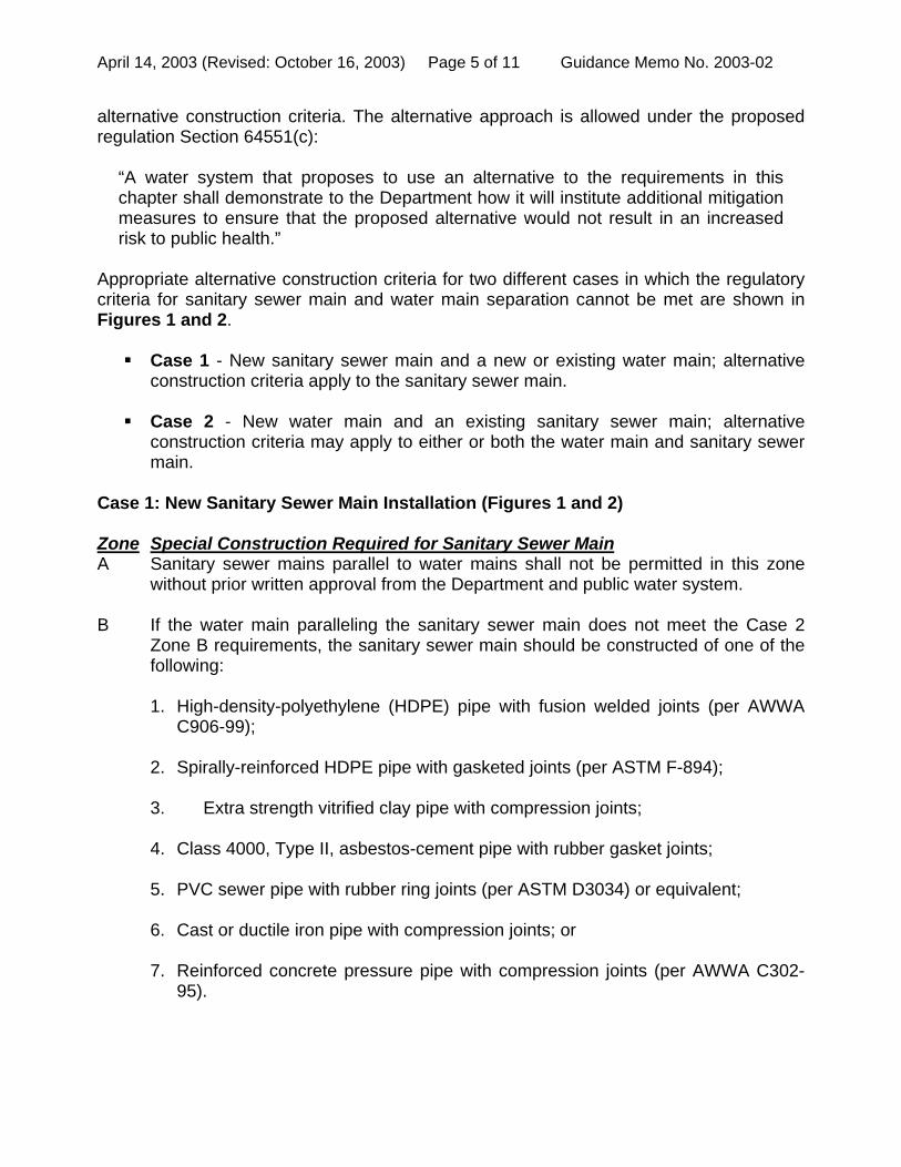
April 14, 2003 (Revised: October 16, 2003) Page 5 of 11 Guidance Memo No. 2003-02
alternative construction criteria. The alternative approach is allowed under the proposed regulation Section 64551(c):
“A water system that proposes to use an alternative to the requirements in this chapter shall demonstrate to the Department how it will institute additional mitigation measures to ensure that the proposed alternative would not result in an increased risk to public health.”
Appropriate alternative construction criteria for two different cases in which the regulatory criteria for sanitary sewer main and water main separation cannot be met are shown in Figures 1 and 2. Case 1 - New sanitary sewer main and a new or existing water main; alternative
construction criteria apply to the sanitary sewer main. Case 2 - New water main and an existing sanitary sewer main; alternative
construction criteria may apply to either or both the water main and sanitary sewer main.
Case 1: New Sanitary Sewer Main Installation (Figures 1 and 2) Zone Special Construction Required for Sanitary Sewer Main A Sanitary sewer mains parallel to water mains shall not be permitted in this zone
without prior written approval from the Department and public water system. B If the water main paralleling the sanitary sewer main does not meet the Case 2
Zone B requirements, the sanitary sewer main should be constructed of one of the following:
1. High-density-polyethylene (HDPE) pipe with fusion welded joints (per AWWA
C906-99);
2. Spirally-reinforced HDPE pipe with gasketed joints (per ASTM F-894);
3. Extra strength vitrified clay pipe with compression joints;
4. Class 4000, Type II, asbestos-cement pipe with rubber gasket joints;
5. PVC sewer pipe with rubber ring joints (per ASTM D3034) or equivalent;
6. Cast or ductile iron pipe with compression joints; or
7. Reinforced concrete pressure pipe with compression joints (per AWWA C302-95).
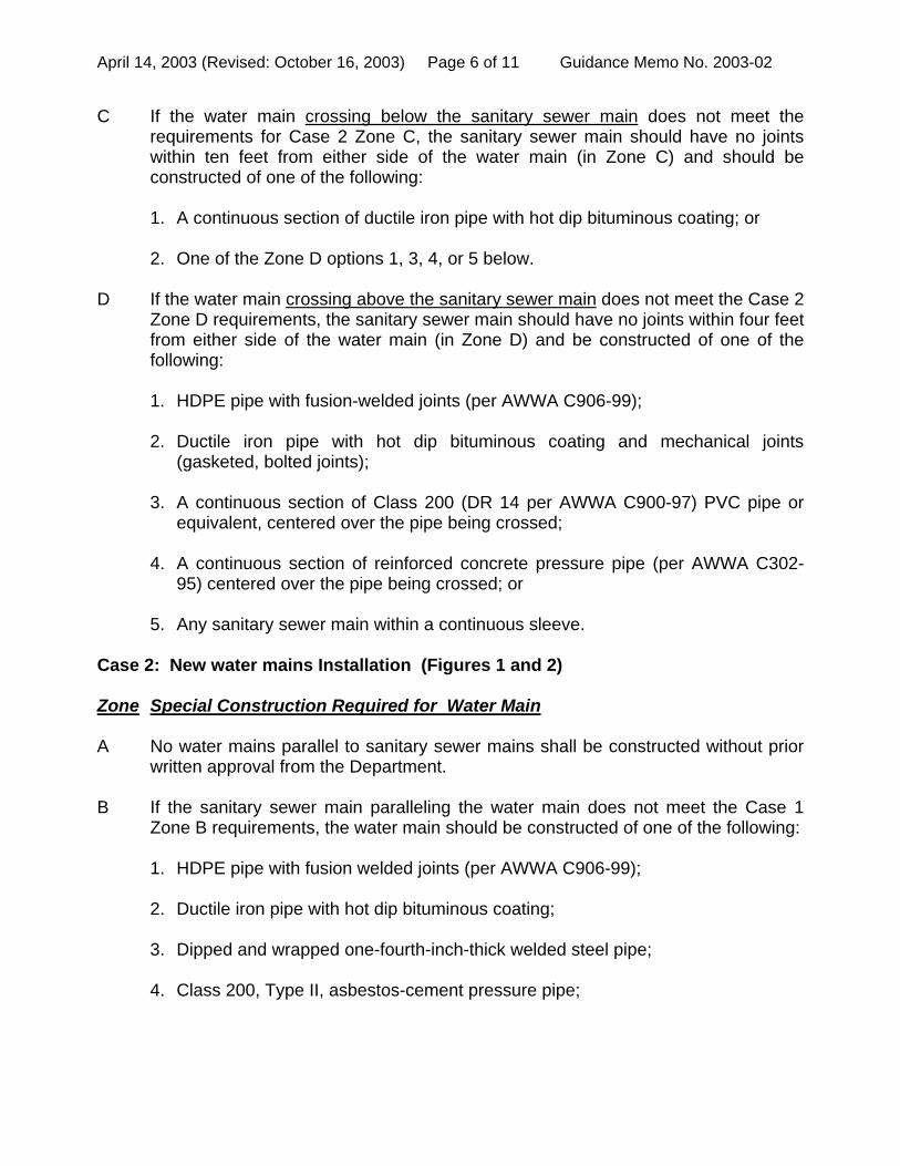
April 14, 2003 (Revised: October 16, 2003) Page 6 of 11 Guidance Memo No. 2003-02
C If the water main crossing below the sanitary sewer main does not meet the requirements for Case 2 Zone C, the sanitary sewer main should have no joints within ten feet from either side of the water main (in Zone C) and should be constructed of one of the following:
1. A continuous section of ductile iron pipe with hot dip bituminous coating; or 2. One of the Zone D options 1, 3, 4, or 5 below.
D If the water main crossing above the sanitary sewer main does not meet the Case 2 Zone D requirements, the sanitary sewer main should have no joints within four feet from either side of the water main (in Zone D) and be constructed of one of the following:
1. HDPE pipe with fusion-welded joints (per AWWA C906-99); 2. Ductile iron pipe with hot dip bituminous coating and mechanical joints
(gasketed, bolted joints);
3. A continuous section of Class 200 (DR 14 per AWWA C900-97) PVC pipe or equivalent, centered over the pipe being crossed;
4. A continuous section of reinforced concrete pressure pipe (per AWWA C302-
95) centered over the pipe being crossed; or
5. Any sanitary sewer main within a continuous sleeve. Case 2: New water mains Installation (Figures 1 and 2) Zone Special Construction Required for Water Main A No water mains parallel to sanitary sewer mains shall be constructed without prior
written approval from the Department. B If the sanitary sewer main paralleling the water main does not meet the Case 1
Zone B requirements, the water main should be constructed of one of the following:
1. HDPE pipe with fusion welded joints (per AWWA C906-99); 2. Ductile iron pipe with hot dip bituminous coating; 3. Dipped and wrapped one-fourth-inch-thick welded steel pipe; 4. Class 200, Type II, asbestos-cement pressure pipe;
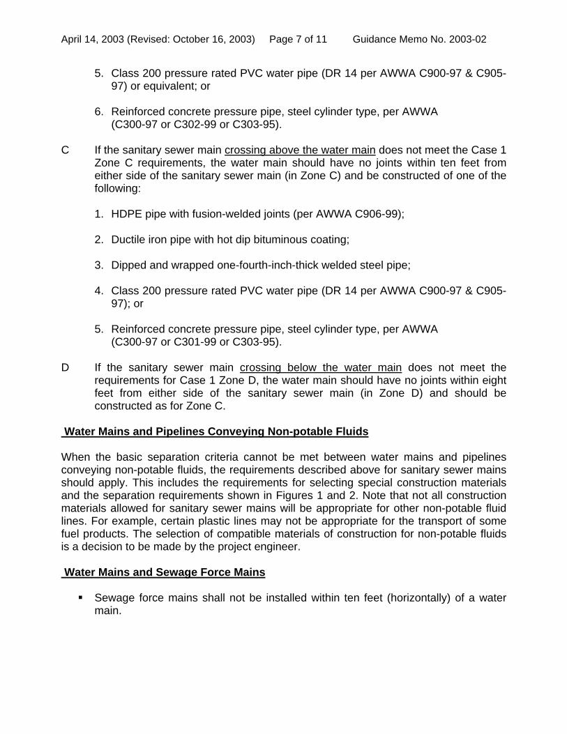
April 14, 2003 (Revised: October 16, 2003) Page 7 of 11 Guidance Memo No. 2003-02
5. Class 200 pressure rated PVC water pipe (DR 14 per AWWA C900-97 & C905-97) or equivalent; or
6. Reinforced concrete pressure pipe, steel cylinder type, per AWWA (C300-97 or C302-99 or C303-95).
C If the sanitary sewer main crossing above the water main does not meet the Case 1 Zone C requirements, the water main should have no joints within ten feet from either side of the sanitary sewer main (in Zone C) and be constructed of one of the following:
1. HDPE pipe with fusion-welded joints (per AWWA C906-99); 2. Ductile iron pipe with hot dip bituminous coating; 3. Dipped and wrapped one-fourth-inch-thick welded steel pipe; 4. Class 200 pressure rated PVC water pipe (DR 14 per AWWA C900-97 & C905-
97); or 5. Reinforced concrete pressure pipe, steel cylinder type, per AWWA (C300-97 or C301-99 or C303-95).
D If the sanitary sewer main crossing below the water main does not meet the requirements for Case 1 Zone D, the water main should have no joints within eight feet from either side of the sanitary sewer main (in Zone D) and should be constructed as for Zone C.
Water Mains and Pipelines Conveying Non-potable Fluids When the basic separation criteria cannot be met between water mains and pipelines conveying non-potable fluids, the requirements described above for sanitary sewer mains should apply. This includes the requirements for selecting special construction materials and the separation requirements shown in Figures 1 and 2. Note that not all construction materials allowed for sanitary sewer mains will be appropriate for other non-potable fluid lines. For example, certain plastic lines may not be appropriate for the transport of some fuel products. The selection of compatible materials of construction for non-potable fluids is a decision to be made by the project engineer. Water Mains and Sewage Force Mains Sewage force mains shall not be installed within ten feet (horizontally) of a water
main.
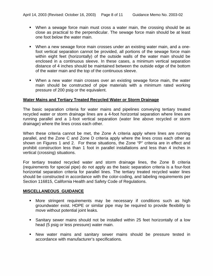
April 14, 2003 (Revised: October 16, 2003) Page 8 of 11 Guidance Memo No. 2003-02
When a sewage force main must cross a water main, the crossing should be as close as practical to the perpendicular. The sewage force main should be at least one foot below the water main.
When a new sewage force main crosses under an existing water main, and a one-
foot vertical separation cannot be provided, all portions of the sewage force main within eight feet (horizontally) of the outside walls of the water main should be enclosed in a continuous sleeve. In these cases, a minimum vertical separation distance of 4 inches should be maintained between the outside edge of the bottom of the water main and the top of the continuous sleeve.
When a new water main crosses over an existing sewage force main, the water
main should be constructed of pipe materials with a minimum rated working pressure of 200 psig or the equivalent.
Water Mains and Tertiary Treated Recycled Water or Storm Drainage The basic separation criteria for water mains and pipelines conveying tertiary treated recycled water or storm drainage lines are a 4-foot horizontal separation where lines are running parallel and a 1-foot vertical separation (water line above recycled or storm drainage) where the lines cross each other. When these criteria cannot be met, the Zone A criteria apply where lines are running parallel, and the Zone C and Zone D criteria apply where the lines cross each other as shown on Figures 1 and 2. For these situations, the Zone “P” criteria are in effect and prohibit construction less than 1 foot in parallel installations and less than 4 inches in vertical (crossing) situations. For tertiary treated recycled water and storm drainage lines, the Zone B criteria (requirements for special pipe) do not apply as the basic separation criteria is a four-foot horizontal separation criteria for parallel lines. The tertiary treated recycled water lines should be constructed in accordance with the color-coding, and labeling requirements per Section 116815, California Health and Safety Code of Regulations. MISCELLANEOUS GUIDANCE More stringent requirements may be necessary if conditions such as high
groundwater exist. HDPE or similar pipe may be required to provide flexibility to move without potential joint leaks.
Sanitary sewer mains should not be installed within 25 feet horizontally of a low
head (5 psig or less pressure) water main. New water mains and sanitary sewer mains should be pressure tested in
accordance with manufacturer’s specifications.

April 14, 2003 (Revised: October 16, 2003) Page 9 of 11 Guidance Memo No. 2003-02
When installing water mains, sewers, or other pipelines, measures should be taken to prevent or minimize disturbances of existing pipelines. Disturbance of the conduit’s supporting base could eventually result in pipeline failure.
Special consideration should be given to the selection of pipe materials if corrosive
conditions are likely to exist. These conditions may be due to soil type and/or the nature of the fluid conveyed in the conduit, such as a septic sewage producing corrosive hydrogen sulfide.
NOTE: Dimensions are from the outside of the water main to the outside of the other pipeline, manhole, or sleeve.
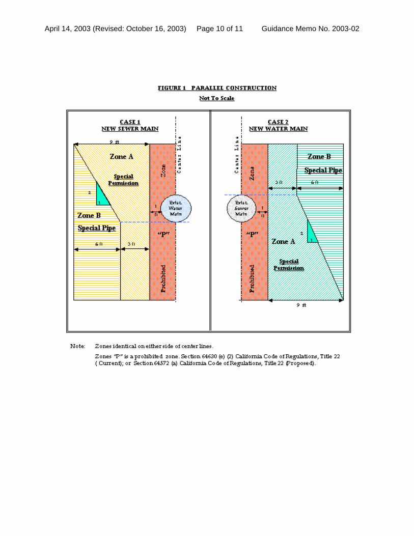
April 14, 2003 (Revised: October 16, 2003) Page 10 of 11 Guidance Memo No. 2003-02
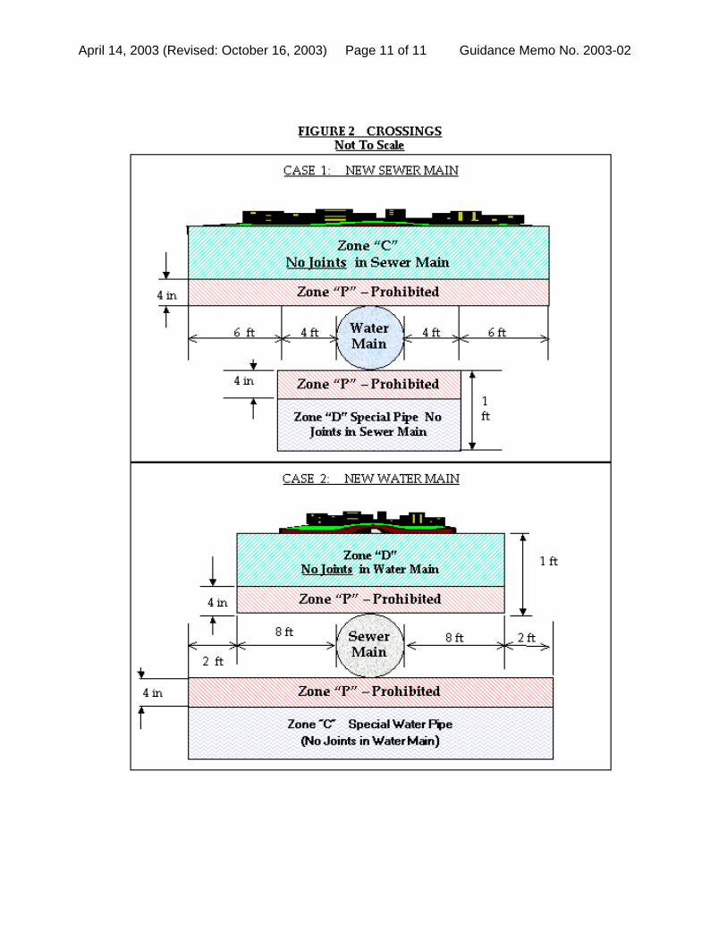
April 14, 2003 (Revised: October 16, 2003) Page 11 of 11 Guidance Memo No. 2003-02
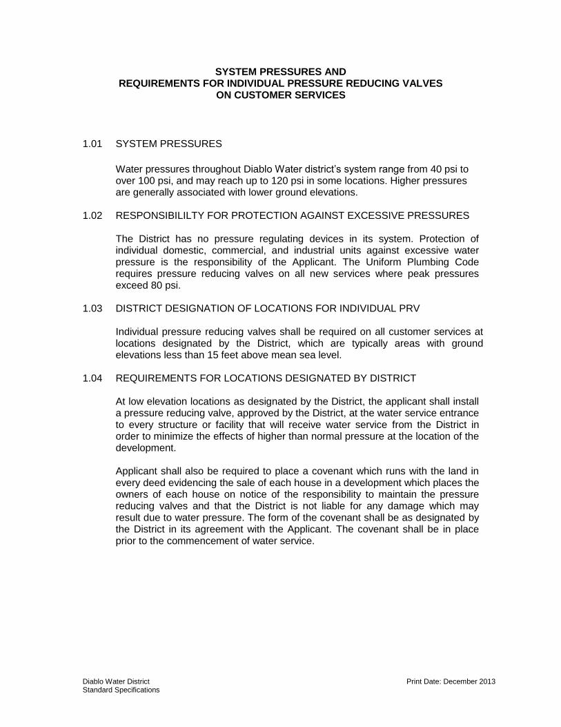
Diablo Water District Print Date: December 2013 Standard Specifications
SYSTEM PRESSURES AND REQUIREMENTS FOR INDIVIDUAL PRESSURE REDUCING VALVES
ON CUSTOMER SERVICES
1.01 SYSTEM PRESSURES
Water pressures throughout Diablo Water district’s system range from 40 psi to over 100 psi, and may reach up to 120 psi in some locations. Higher pressures are generally associated with lower ground elevations.
1.02 RESPONSIBILILTY FOR PROTECTION AGAINST EXCESSIVE PRESSURES
The District has no pressure regulating devices in its system. Protection of individual domestic, commercial, and industrial units against excessive water pressure is the responsibility of the Applicant. The Uniform Plumbing Code requires pressure reducing valves on all new services where peak pressures exceed 80 psi.
1.03 DISTRICT DESIGNATION OF LOCATIONS FOR INDIVIDUAL PRV
Individual pressure reducing valves shall be required on all customer services at locations designated by the District, which are typically areas with ground elevations less than 15 feet above mean sea level.
1.04 REQUIREMENTS FOR LOCATIONS DESIGNATED BY DISTRICT
At low elevation locations as designated by the District, the applicant shall install a pressure reducing valve, approved by the District, at the water service entrance to every structure or facility that will receive water service from the District in order to minimize the effects of higher than normal pressure at the location of the development. Applicant shall also be required to place a covenant which runs with the land in every deed evidencing the sale of each house in a development which places the owners of each house on notice of the responsibility to maintain the pressure reducing valves and that the District is not liable for any damage which may result due to water pressure. The form of the covenant shall be as designated by the District in its agreement with the Applicant. The covenant shall be in place prior to the commencement of water service.
9. Construction Activities
DIABLO WATER DISTRICT STANDARD SPECIFICATIONS AND DRAWINGS
CONSTRUCTION ACTIVITIES
I. Construction Sequence and Requirements
II. Construction Submittal Checklist
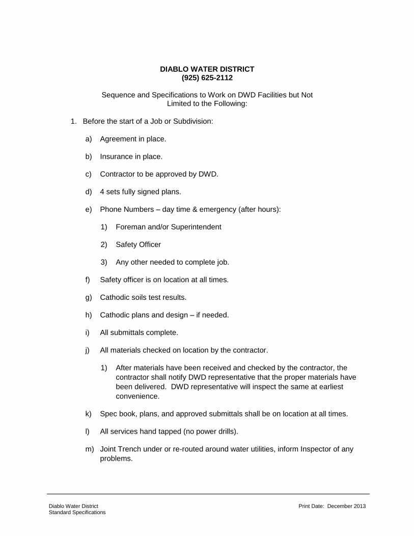
Diablo Water District Print Date: December 2013 Standard Specifications
DIABLO WATER DISTRICT (925) 625-2112
Sequence and Specifications to Work on DWD Facilities but Not
Limited to the Following:
1. Before the start of a Job or Subdivision:
a) Agreement in place.
b) Insurance in place.
c) Contractor to be approved by DWD.
d) 4 sets fully signed plans.
e) Phone Numbers – day time & emergency (after hours):
1) Foreman and/or Superintendent
2) Safety Officer
3) Any other needed to complete job.
f) Safety officer is on location at all times.
g) Cathodic soils test results.
h) Cathodic plans and design – if needed.
i) All submittals complete.
j) All materials checked on location by the contractor.
1) After materials have been received and checked by the contractor, the
contractor shall notify DWD representative that the proper materials have
been delivered. DWD representative will inspect the same at earliest
convenience.
k) Spec book, plans, and approved submittals shall be on location at all times.
l) All services hand tapped (no power drills).
m) Joint Trench under or re-routed around water utilities, inform Inspector of any
problems.
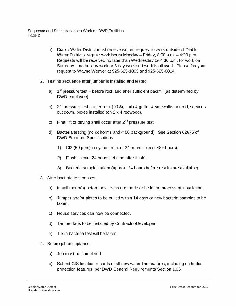
Sequence and Specifications to Work on DWD Facilities Page 2
Diablo Water District Print Date: December 2013 Standard Specifications
n) Diablo Water District must receive written request to work outside of Diablo
Water District’s regular work hours Monday – Friday, 8:00 a.m. – 4:30 p.m.
Requests will be received no later than Wednesday @ 4:30 p.m. for work on
Saturday – no holiday work or 3 day weekend work is allowed. Please fax your
request to Wayne Weaver at 925-625-1803 and 925-625-0814.
2. Testing sequence after jumper is installed and tested.
a) 1st pressure test – before rock and after sufficient backfill (as determined by
DWD employee).
b) 2nd pressure test – after rock (90%), curb & gutter & sidewalks poured, services
cut down, boxes installed (on 2 x 4 redwood).
c) Final lift of paving shall occur after 2nd pressure test.
d) Bacteria testing (no coliforms and < 50 background). See Section 02675 of
DWD Standard Specifications.
1) Cl2 (50 ppm) in system min. of 24 hours – (best 48+ hours).
2) Flush – (min. 24 hours set time after flush).
3) Bacteria samples taken (approx. 24 hours before results are available).
3. After bacteria test passes:
a) Install meter(s) before any tie-ins are made or be in the process of installation.
b) Jumper and/or plates to be pulled within 14 days or new bacteria samples to be
taken.
c) House services can now be connected.
d) Tamper tags to be installed by Contractor/Developer.
e) Tie-in bacteria test will be taken.
4. Before job acceptance:
a) Job must be completed.
b) Submit GIS location records of all new water line features, including cathodic
protection features, per DWD General Requirements Section 1.06.
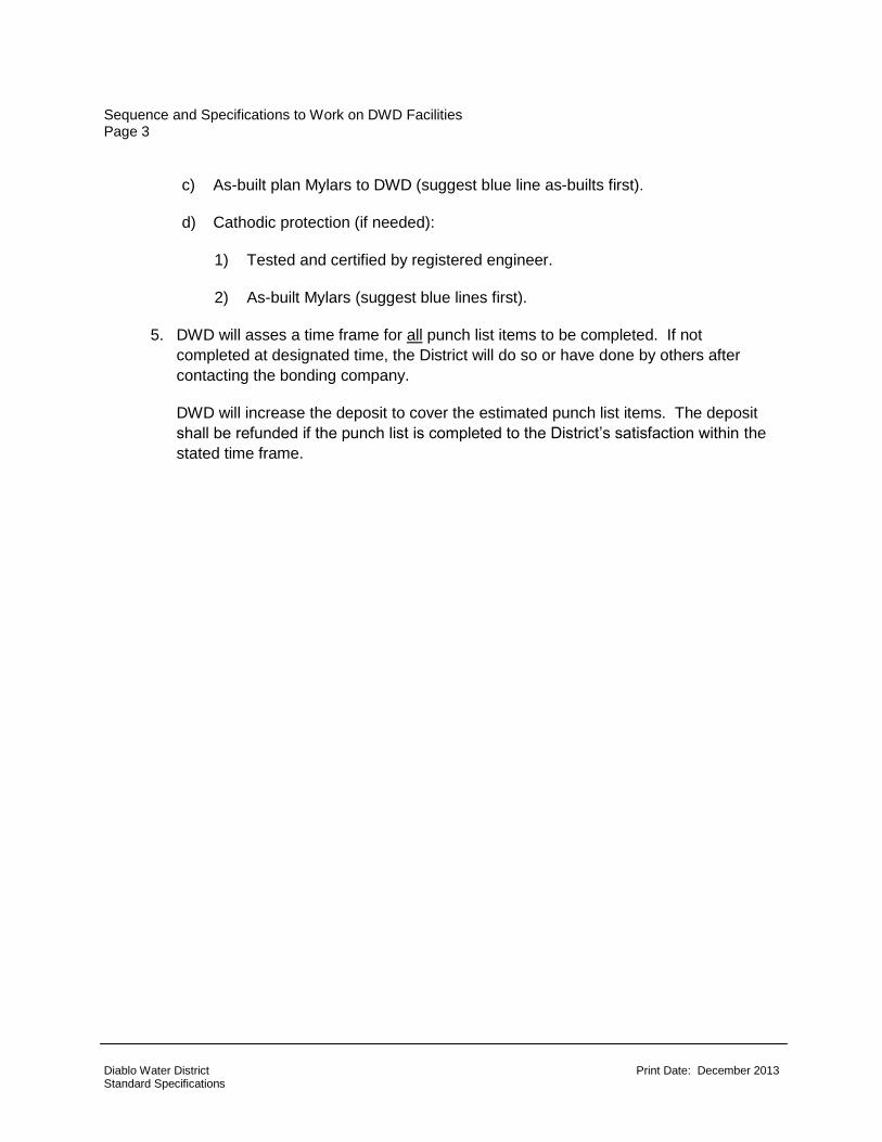
Sequence and Specifications to Work on DWD Facilities Page 3
Diablo Water District Print Date: December 2013 Standard Specifications
c) As-built plan Mylars to DWD (suggest blue line as-builts first).
d) Cathodic protection (if needed):
1) Tested and certified by registered engineer.
2) As-built Mylars (suggest blue lines first).
5. DWD will asses a time frame for all punch list items to be completed. If not
completed at designated time, the District will do so or have done by others after
contacting the bonding company.
DWD will increase the deposit to cover the estimated punch list items. The deposit
shall be refunded if the punch list is completed to the District’s satisfaction within the
stated time frame.
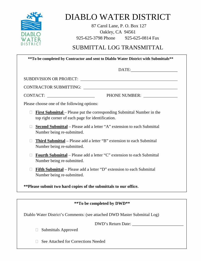
DIABLO WATER DISTRICT 87 Carol Lane, P. O. Box 127
Oakley, CA 94561 925-625-3798 Phone 925-625-0814 Fax
SUBMITTAL LOG TRANSMITTAL
**To be completed by Contractor and sent to Diablo Water District with Submittals**
DATE:
SUBDIVISION OR PROJECT:
CONTRACTOR SUBMITTING:
CONTACT: PHONE NUMBER:
Please choose one of the following options:
� First Submittal – Please put the corresponding Submittal Number in the top right corner of each page for identification.
� Second Submittal – Please add a letter “A” extension to each Submittal Number being re-submitted.
� Third Submittal – Please add a letter “B” extension to each Submittal Number being re-submitted.
� Fourth Submittal – Please add a letter “C” extension to each Submittal Number being re-submitted.
� Fifth Submittal – Please add a letter “D” extension to each Submittal Number being re-submitted.
**Please submit two hard copies of the submittals to our office.
**To be completed by DWD**
Diablo Water District’s Comments: (see attached DWD Master Submittal Log)
DWD’s Return Date: � Submittals Approved
� See Attached for Corrections Needed
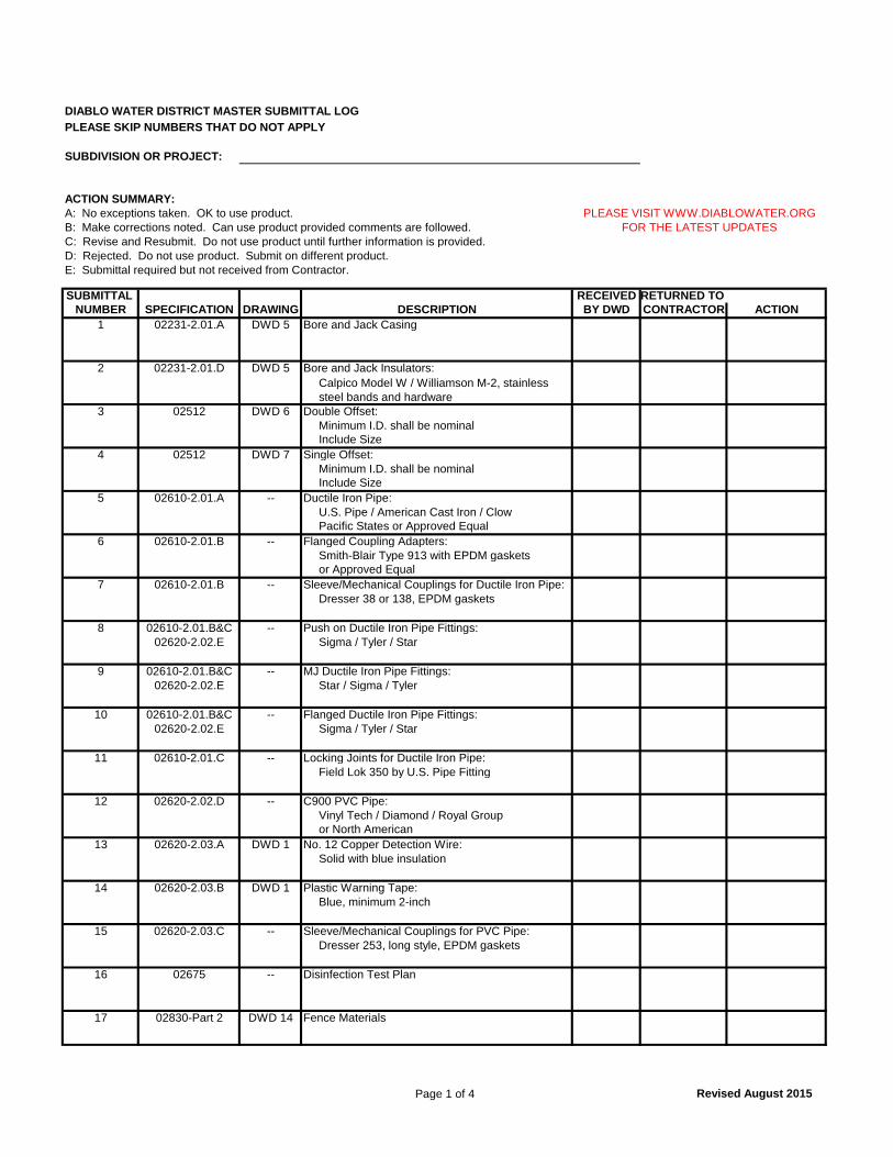
Page 1 of 4 Revised August 2015
DIABLO WATER DISTRICT MASTER SUBMITTAL LOGPLEASE SKIP NUMBERS THAT DO NOT APPLY
SUBDIVISION OR PROJECT:
ACTION SUMMARY:A: No exceptions taken. OK to use product.B: Make corrections noted. Can use product provided comments are followed.C: Revise and Resubmit. Do not use product until further information is provided.D: Rejected. Do not use product. Submit on different product.E: Submittal required but not received from Contractor.
SUBMITTAL RECEIVED RETURNED TO NUMBER SPECIFICATION DRAWING BY DWD CONTRACTOR ACTION
1 02231-2.01.A DWD 5 Bore and Jack Casing
2 02231-2.01.D DWD 5 Bore and Jack Insulators:
3 02512 DWD 6 Double Offset:Minimum I.D. shall be nominalInclude Size
4 02512 DWD 7 Single Offset: Minimum I.D. shall be nominalInclude Size
5 02610-2.01.A -- Ductile Iron Pipe: U.S. Pipe / American Cast Iron / ClowPacific States or Approved Equal
6 02610-2.01.B -- Flanged Coupling Adapters: Smith-Blair Type 913 with EPDM gaskets or Approved Equal
7 02610-2.01.B -- Sleeve/Mechanical Couplings for Ductile Iron Pipe: Dresser 38 or 138, EPDM gaskets
8 02610-2.01.B&C -- Push on Ductile Iron Pipe Fittings: 02620-2.02.E Sigma / Tyler / Star
9 02610-2.01.B&C -- MJ Ductile Iron Pipe Fittings: 02620-2.02.E Star / Sigma / Tyler
10 02610-2.01.B&C -- Flanged Ductile Iron Pipe Fittings: 02620-2.02.E Sigma / Tyler / Star
11 02610-2.01.C -- Locking Joints for Ductile Iron Pipe: Field Lok 350 by U.S. Pipe Fitting
12 02620-2.02.D -- C900 PVC Pipe: Vinyl Tech / Diamond / Royal Groupor North American
13 02620-2.03.A DWD 1 No. 12 Copper Detection Wire: Solid with blue insulation
14 02620-2.03.B DWD 1 Plastic Warning Tape:Blue, minimum 2-inch
15 02620-2.03.C -- Sleeve/Mechanical Couplings for PVC Pipe: Dresser 253, long style, EPDM gaskets
16 02675 -- Disinfection Test Plan
17 02830-Part 2 DWD 14 Fence Materials
DESCRIPTION
Calpico Model W / Williamson M-2, stainless steel bands and hardware
PLEASE VISIT WWW.DIABLOWATER.ORGFOR THE LATEST UPDATES
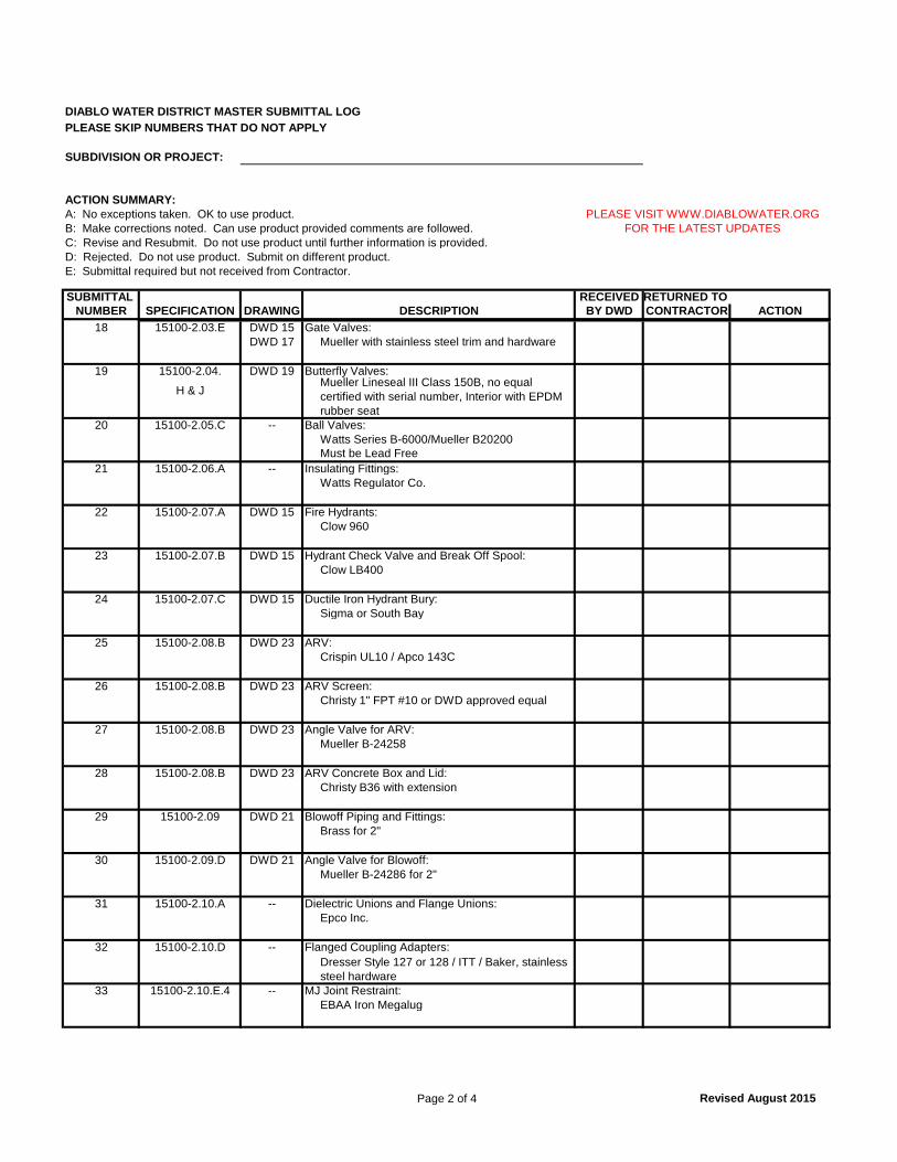
Page 2 of 4 Revised August 2015
DIABLO WATER DISTRICT MASTER SUBMITTAL LOGPLEASE SKIP NUMBERS THAT DO NOT APPLY
SUBDIVISION OR PROJECT:
ACTION SUMMARY:A: No exceptions taken. OK to use product.B: Make corrections noted. Can use product provided comments are followed.C: Revise and Resubmit. Do not use product until further information is provided.D: Rejected. Do not use product. Submit on different product.E: Submittal required but not received from Contractor.
SUBMITTAL RECEIVED RETURNED TO NUMBER SPECIFICATION DRAWING BY DWD CONTRACTOR ACTIONDESCRIPTION
PLEASE VISIT WWW.DIABLOWATER.ORGFOR THE LATEST UPDATES
18 15100-2.03.E DWD 15 Gate Valves: DWD 17 Mueller with stainless steel trim and hardware
19 15100-2.04. DWD 19 Butterfly Valves:
H & J
20 15100-2.05.C -- Ball Valves: Watts Series B-6000/Mueller B20200Must be Lead Free
21 15100-2.06.A -- Insulating Fittings:Watts Regulator Co.
22 15100-2.07.A DWD 15 Fire Hydrants: Clow 960
23 15100-2.07.B DWD 15 Hydrant Check Valve and Break Off Spool:Clow LB400
24 15100-2.07.C DWD 15 Ductile Iron Hydrant Bury: Sigma or South Bay
25 15100-2.08.B DWD 23 ARV: Crispin UL10 / Apco 143C
26 15100-2.08.B DWD 23 ARV Screen:Christy 1" FPT #10 or DWD approved equal
27 15100-2.08.B DWD 23 Angle Valve for ARV:Mueller B-24258
28 15100-2.08.B DWD 23 ARV Concrete Box and Lid: Christy B36 with extension
29 15100-2.09 DWD 21 Blowoff Piping and Fittings: Brass for 2"
30 15100-2.09.D DWD 21 Angle Valve for Blowoff: Mueller B-24286 for 2"
31 15100-2.10.A -- Dielectric Unions and Flange Unions:Epco Inc.
32 15100-2.10.D -- Flanged Coupling Adapters:
33 15100-2.10.E.4 -- MJ Joint Restraint: EBAA Iron Megalug
Mueller Lineseal III Class 150B, no equal certified with serial number, Interior with EPDM rubber seat
Dresser Style 127 or 128 / ITT / Baker, stainless steel hardware
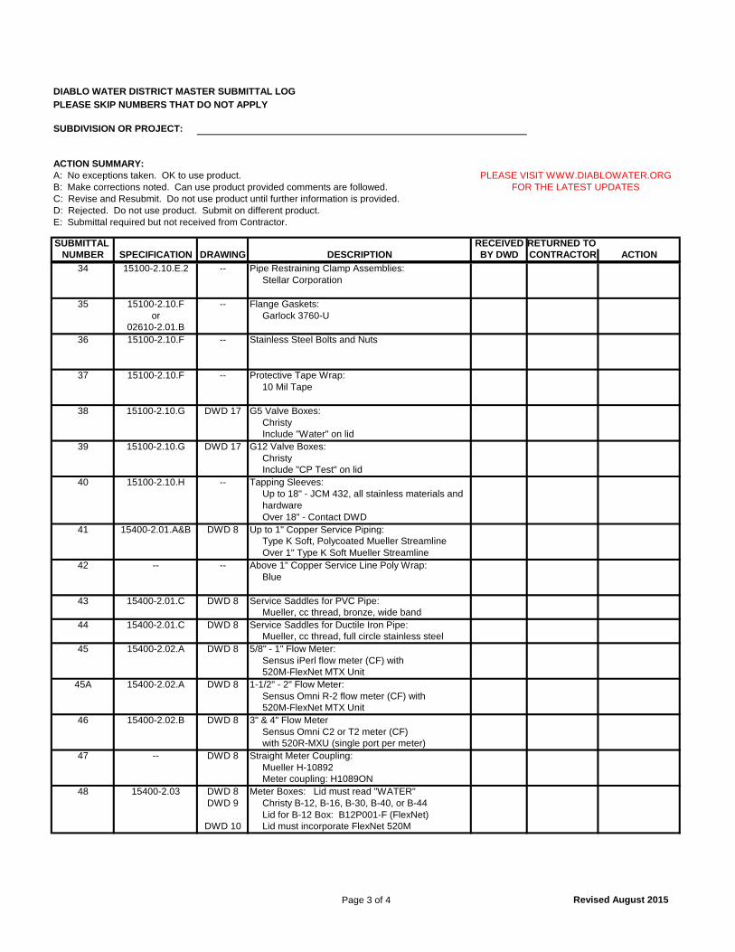
Page 3 of 4 Revised August 2015
DIABLO WATER DISTRICT MASTER SUBMITTAL LOGPLEASE SKIP NUMBERS THAT DO NOT APPLY
SUBDIVISION OR PROJECT:
ACTION SUMMARY:A: No exceptions taken. OK to use product.B: Make corrections noted. Can use product provided comments are followed.C: Revise and Resubmit. Do not use product until further information is provided.D: Rejected. Do not use product. Submit on different product.E: Submittal required but not received from Contractor.
SUBMITTAL RECEIVED RETURNED TO NUMBER SPECIFICATION DRAWING BY DWD CONTRACTOR ACTIONDESCRIPTION
PLEASE VISIT WWW.DIABLOWATER.ORGFOR THE LATEST UPDATES
34 15100-2.10.E.2 -- Pipe Restraining Clamp Assemblies:Stellar Corporation
35 15100-2.10.F -- Flange Gaskets: or Garlock 3760-U
02610-2.01.B36 15100-2.10.F -- Stainless Steel Bolts and Nuts
37 15100-2.10.F -- Protective Tape Wrap:10 Mil Tape
38 15100-2.10.G DWD 17 G5 Valve Boxes: ChristyInclude "Water" on lid
39 15100-2.10.G DWD 17 G12 Valve Boxes: ChristyInclude "CP Test" on lid
40 15100-2.10.H -- Tapping Sleeves: Up to 18" - JCM 432, all stainless materials and hardwareOver 18" - Contact DWD
41 15400-2.01.A&B DWD 8 Up to 1" Copper Service Piping: Type K Soft, Polycoated Mueller StreamlineOver 1" Type K Soft Mueller Streamline
42 -- -- Above 1" Copper Service Line Poly Wrap: Blue
43 15400-2.01.C DWD 8 Service Saddles for PVC Pipe: Mueller, cc thread, bronze, wide band
44 15400-2.01.C DWD 8 Service Saddles for Ductile Iron Pipe: Mueller, cc thread, full circle stainless steel
45 15400-2.02.A DWD 8 5/8" - 1" Flow Meter:Sensus iPerl flow meter (CF) with 520M-FlexNet MTX Unit
45A 15400-2.02.A DWD 8 1-1/2" - 2" Flow Meter:Sensus Omni R-2 flow meter (CF) with520M-FlexNet MTX Unit
46 15400-2.02.B DWD 8 3" & 4" Flow MeterSensus Omni C2 or T2 meter (CF) with 520R-MXU (single port per meter)
47 -- DWD 8 Straight Meter Coupling:Mueller H-10892Meter coupling: H1089ON
48 15400-2.03 DWD 8 Meter Boxes: Lid must read "WATER"DWD 9 Christy B-12, B-16, B-30, B-40, or B-44
Lid for B-12 Box: B12P001-F (FlexNet)DWD 10 Lid must incorporate FlexNet 520M
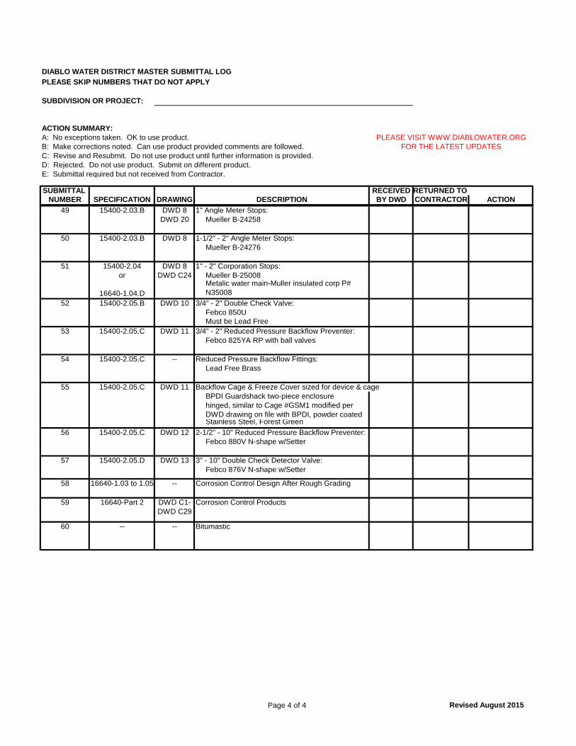
Page 4 of 4 Revised August 2015
DIABLO WATER DISTRICT MASTER SUBMITTAL LOGPLEASE SKIP NUMBERS THAT DO NOT APPLY
SUBDIVISION OR PROJECT:
ACTION SUMMARY:A: No exceptions taken. OK to use product.B: Make corrections noted. Can use product provided comments are followed.C: Revise and Resubmit. Do not use product until further information is provided.D: Rejected. Do not use product. Submit on different product.E: Submittal required but not received from Contractor.
SUBMITTAL RECEIVED RETURNED TO NUMBER SPECIFICATION DRAWING BY DWD CONTRACTOR ACTIONDESCRIPTION
PLEASE VISIT WWW.DIABLOWATER.ORGFOR THE LATEST UPDATES
49 15400-2.03.B DWD 8 1" Angle Meter Stops: DWD 20 Mueller B-24258
50 15400-2.03.B DWD 8 1-1/2" - 2" Angle Meter Stops: Mueller B-24276
51 15400-2.04 DWD 8 1" - 2" Corporation Stops:or DWD C24 Mueller B-25008
16640-1.04.DMetalic water main-Muller insulated corp P# N35008
52 15400-2.05.B DWD 10 3/4" - 2" Double Check Valve: Febco 850U Must be Lead Free
53 15400-2.05.C DWD 11 3/4" - 2" Reduced Pressure Backflow Preventer: Febco 825YA RP with ball valves
54 15400-2.05.C -- Reduced Pressure Backflow Fittings: Lead Free Brass
55 15400-2.05.C DWD 11 Backflow Cage & Freeze Cover sized for device & cageBPDI Guardshack two-piece enclosurehinged, similar to Cage #GSM1 modified per DWD drawing on file with BPDI, powder coated Stainless Steel, Forest Green
56 15400-2.05.C DWD 12 2-1/2" - 10" Reduced Pressure Backflow Preventer: Febco 880V N-shape w/Setter
57 15400-2.05.D DWD 13 3" - 10" Double Check Detector Valve: Febco 876V N-shape w/Setter
58 16640-1.03 to 1.05 -- Corrosion Control Design After Rough Grading
59 16640-Part 2 DWD C1- Corrosion Control ProductsDWD C29
60 -- -- Bitumastic