Embed Size (px)
Citation preview
Centerville City Standard Specifications
CENTERVILLE CITY STANDARD SPECIFICATIONS and DRAWINGS
FOR SUBDIVISON and SITE PLAN DEVELOPMENT (Amended January 2009)
Table of Contents
Division 01 - General Requirements
Summary Section 01 11 00 ........................................................................Summary of Specifications Quality Requirements Section 01 42 19 ..................................................................................................References Section 01 43 00 ......................................................................................Quality Assurance Temporary Facilities and Controls Section 01 55 26 ........................................................................................... Traffic Control Section 01 57 00 ...................................................................................Temporary Controls Product Requirements Section 01 65 00 ................................................................. Product Delivery and Handling Section 01 66 00 ..................................................................Product Storage and Protection
Division 02 - Existing Conditions
Demolition and Structure Moving Section 02 41 13 .......................................................................... Selective Site Demolition Section 02 41 14 .................................................................................... Pavement Removal Section 02 41 15 ................................................................................ Pavement Pulverizing
Division 03 - Concrete Concrete Forming and Accessories Section 03 11 00 ...................................................................................... Concrete Forming Section 03 15 15 ..............................................................Expansion and Contraction Joints
Concrete Reinforcing Section 03 20 00 .................................................................................Concrete Reinforcing Cast-in-place Concrete
Centerville City Standard Specifications
Section 03 30 04 ..................................................................................................... Concrete Section 03 30 05 ........................................................................................ Concrete Testing Section 03 30 10 ................................................................................... Concrete Placement Section 03 35 00 .....................................................................................Concrete Finishing Section 03 38 00 ........................................................................... Post-Tensioned Concrete Section 03 39 00 .........................................................................................Concrete Curing Precast Concrete Section 03 40 00 ........................................................................................ Precast Concrete Grouting Section 03 61 00 ....................................................................................Cementitious Grout
Division 07 - Thermal and Moisture Protection
Damp Proofing and Water Proofing Section 07 19 00 ........................................................................................Water Repellants Joint Protection Section 07 92 00 ............................................................................................. Joint Sealants
Division 26 - Electrical
Electrical General Section 26 05 00 ............................................................... Electrical General Requirements Section 26 05 13 .............................................................................. Conductors and Cables Section 26 05 33 .....................................................................................................Raceway Section 26 05 34 ..................................................................... Electrical Boxes and Fittings Section 26 09 26 ................................................................................................. Panelboard Medium-Voltage Electrical Distribution Section 26 13 13 ...........................................................................................Circuit Breaker Low-Voltage Electrical Transmission Section 26 29 13 ...................................................................................... Motor Controllers Lighting Section 26 56 19 .........................................................................Roadway Lighting System
Division 31 - Earthwork
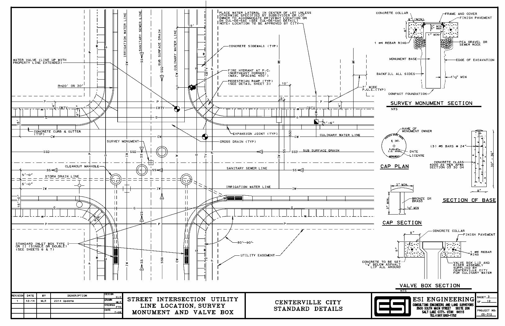
Earthwork General Section 31 05 10 .............................................. Boundary Markers and Survey Monuments
Centerville City Standard Specifications
Section 31 05 13 .............................................................................................. Common Fill Section 31 05 15 ................................................................................... Cement Treated Fill Section 31 05 19 ................................................................................................. Geotextiles Section 31 05 21 ........................................................................... Geogrids/Geocomposites Section 31 05 23.13 .................................................... Flowable Fill for Trench Excavation
Site Clearing Section 31 11 00 .............................................................................................. Site Clearing Earth Moving Section 31 23 16 ................................................................................................. Excavation Section 31 23 17 ............................................................................................Rock Removal Section 31 23 23 ...........................................................................Backfilling for Structures Section 31 23 26 .............................................................. Soil Compaction Quality Control Section 31 25 00 ...........................................................Erosion and Sedimentation Control Earthwork Methods Section 31 31 19 .....................................................................................Vegetation Control Section 31 36 00 ...................................................................................................... Gabions Section 31 37 00 .........................................................................................................Riprap Section 31 41 00 .......................................................................................................Shoring
Division 32 - Exterior Improvements
Exterior Improvements General Section 32 01 05 ...........................................Information, Regulatory, And Warning Signs Section 32 01 06 ................................................................................... Post Mounted Signs Section 32 01 07 ..........................................Relocate Post Mounted Signs and Mail Boxes Section 32 01 10 ........................................................................ Relocate Fences and Gates Section 32 01 13 ..................................................................................................Slurry Seal Section 32 01 14 ....................................................................................................Chip Seal Section 32 01 15 .................................................................................... Micro-Surface Seal Section 32 01 17 ................................................................................ Pavement Crack Seal Section 32 01 26 ......................................................................................... White Top Inlay Section 32 01 29 ............................................................................Concrete Paving Raising Section 32 01 90 ......................................................................................Plant Maintenance Section 32 01 91 ...................................................................................... Tree Root Cutting Section 32 01 93 .............................................................................................Pruning Trees Section 32 05 10 ................................................................................Backfilling Roadways Bases, Ballasts, and Paving Section 32 11 23 ............................................................................Crushed Aggregate Base Section 32 12 03 ......................................................................................... Paving Asphalts Section 32 12 05 ........................................................................................Asphalt Concrete
Centerville City Standard Specifications
Section 32 12 06 ................................................................................................. Super Pave Section 32 12 13 ................................................................................................. Prime Coat Section 32 12 14 ...................................................................................................Tack Coat Section 32 12 16 .......................................................................... Plant Mix Asphalt Paving Section 32 12 17 .......................................................................... Cold-Mix Asphalt Paving Section 32 13 13 .........................................................................................Concrete Paving Section 32 13 73 ..................................................................Concrete Paving Joint Sealants Section 32 14 13 ............................................................................ Precast Concrete Paving Section 32 14 16 ...................................................................................... Brick Unit Paving Section 32 16 13 .............................................................Driveway, Sidewalk, Curb, Gutter Section 32 16 14 .................................................................................................Curb Ramp Section 32 17 23 ................................................................................... Pavement Markings
Site Improvements Section 32 31 13 .................................................................... Chain Link Fences and Gates Section 32 31 16 ................................................................. Welded Wire Fences and Gates Section 32 32 26 .................................................................................................. Crib Walls
Planting Irrigation Section 32 84 23 ................................................................Underground Irrigation Systems
Planting Preparation Section 32 91 19 .................................................................................... Landscape Grading Planting Section 32 92 00 ........................................................................................ Turf and Grasses Section 32 93 13 .............................................................................................Ground Cover Section 32 93 43 ............................................................................................................ Tree
Division 33 - Utilities
Utilities General Section 33 05 01 ............................................ Acrylonitrile-Butadiene-Styrene (ABS) Pipe Section 33 05 02 ......................................................................... Concrete Pipe and Culvert Section 33 05 03 ................................................................................................Copper Pipe Section 33 05 04 ...............................................................................Corrugated Metal Pipe Section 33 05 05 ........................................................................................Ductile Iron Pipe Section 33 05 06 ..................................................................................... Polyethylene Pipe Section 33 05 07 .............................................................................Polyvinyl Chloride Pipe Section 33 05 08 ........................................................................Pre-Stressed Concrete Pipe Section 33 05 10 ..................................................................................... Vitrified Clay Pipe Section 33 05 14 ...........................................................................Utility Grade Adjustment Section 33 05 20 ..................................................................................Backfilling Trenches Section 33 05 23 ....................................................................Trenchless Utility Installation
Centerville City Standard Specifications
Section 33 05 25 ................................................................................ Pavement Restoration Section 33 08 00 ............................................................. Commissioning of Water Utilities Water Utilities Section 33 11 00 ........................................................ Water Distribution and Transmission Section 33 11 11 .................................................Relocate Water Meters and Fire Hydrants Section 33 12 16 ..............................................................................................Water Valves Section 33 12 19 .....................................................................................................Hydrants Section 33 12 33 ............................................................................................... Water Meter Section 33 13 00 ................................................................................................Disinfection Sanitary Sewerage Utilities Section 33 31 00 ....................................................................... Sanitary Sewerage Systems Storm Drain Utilities Section 33 41 00 ............................................................................Storm Drainage Systems Section 33 47 00 ..........................................................................................................Ponds
Electrical Utilities Section 33 71 73 .......................................................................... Electrical Utility Services
Division 34 - Transportation
Construction and Equipment Section 34 71 13 ......................................................................................... Vehicle Barriers Section 34 71 19 ....................................................................................Vehicle Delineators
SECTION 01 11 00
SUMMARY OF SPECIFICATIONS
PART 1 GENERAL
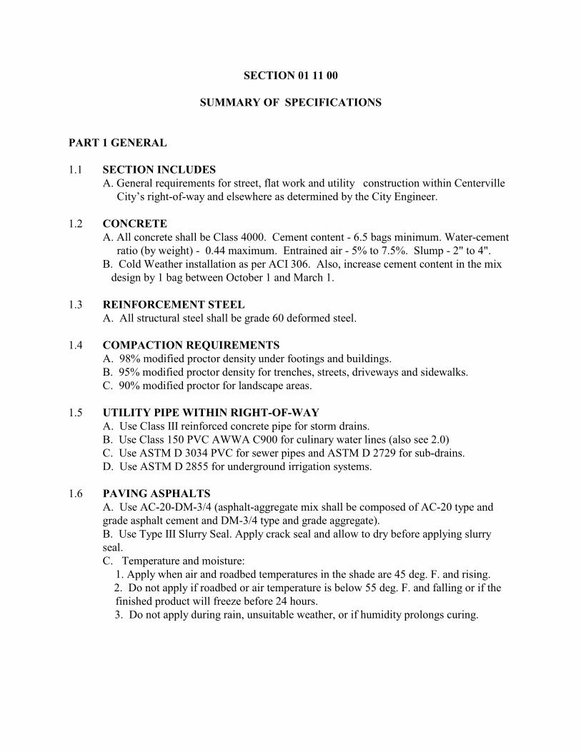
1.1 SECTION INCLUDESA. General requirements for street, flat work and utility construction within Centerville City’s right-of-way and elsewhere as determined by the City Engineer.
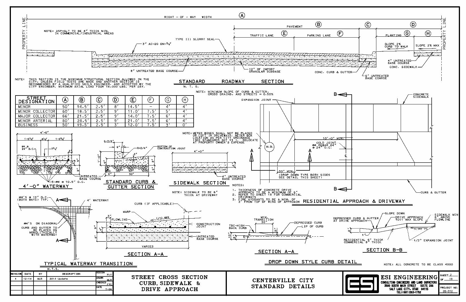
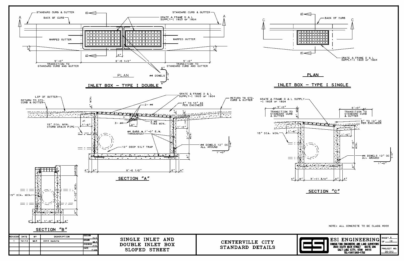
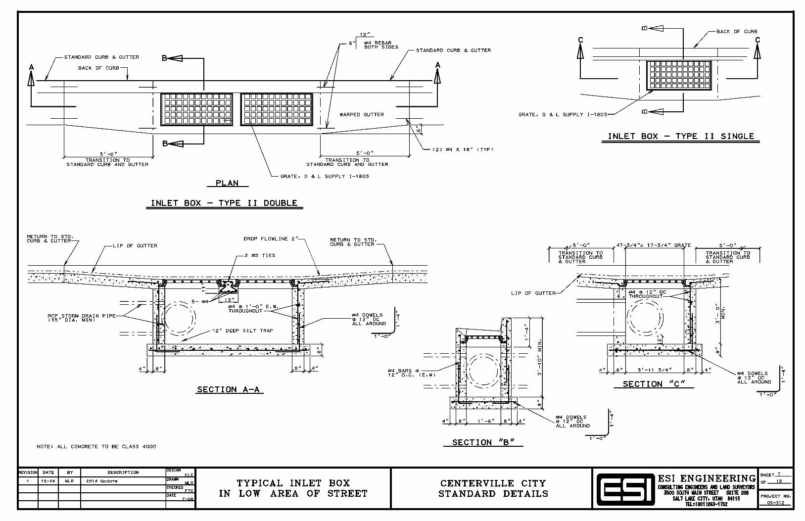
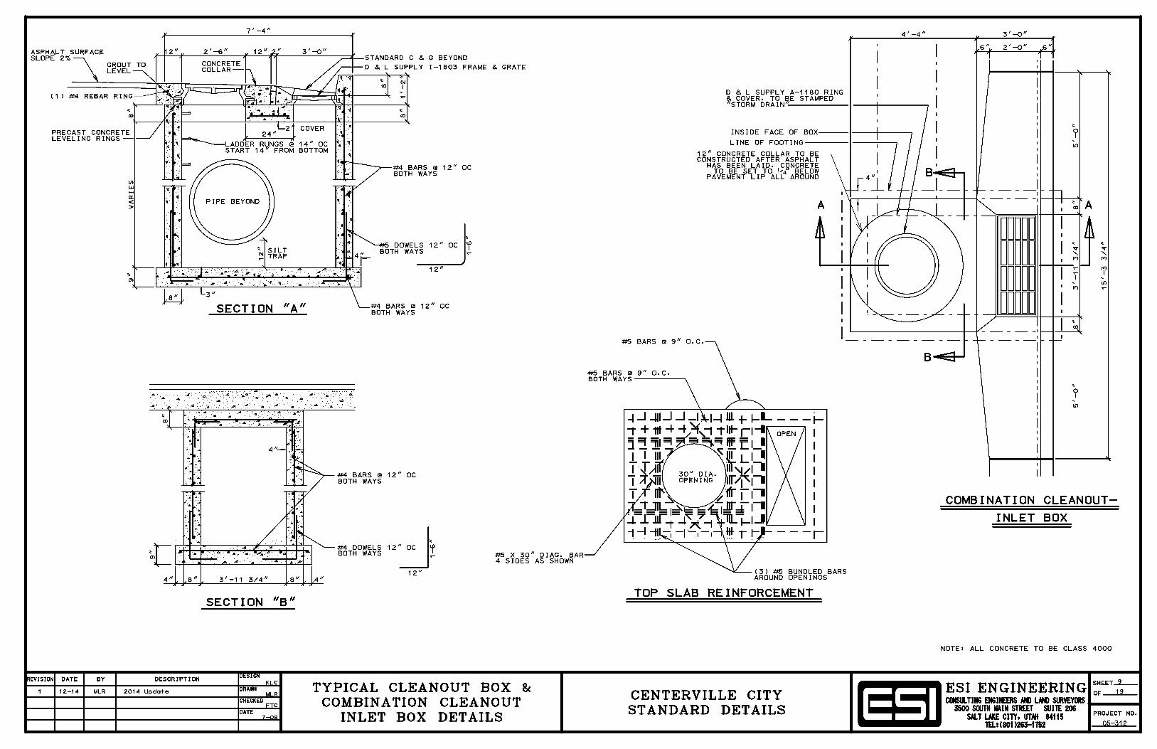
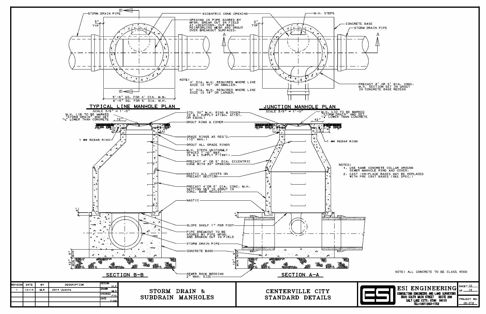
1.2 CONCRETEA. All concrete shall be Class 4000. Cement content - 6.5 bags minimum. Water-cement ratio (by weight) - 0.44 maximum. Entrained air - 5% to 7.5%. Slump - 2" to 4". B. Cold Weather installation as per ACI 306. Also, increase cement content in the mix design by 1 bag between October 1 and March 1.
1.3 REINFORCEMENT STEELA. All structural steel shall be grade 60 deformed steel.
1.4 COMPACTION REQUIREMENTSA. 98% modified proctor density under footings and buildings.B. 95% modified proctor density for trenches, streets, driveways and sidewalks.C. 90% modified proctor for landscape areas.
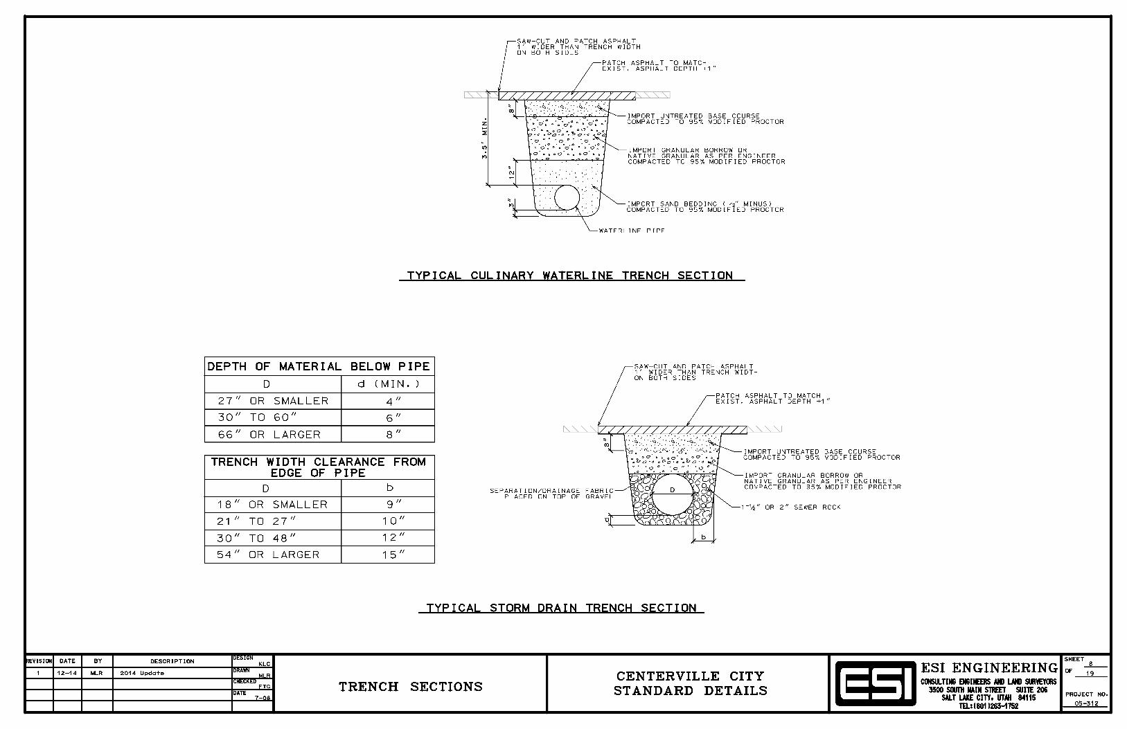
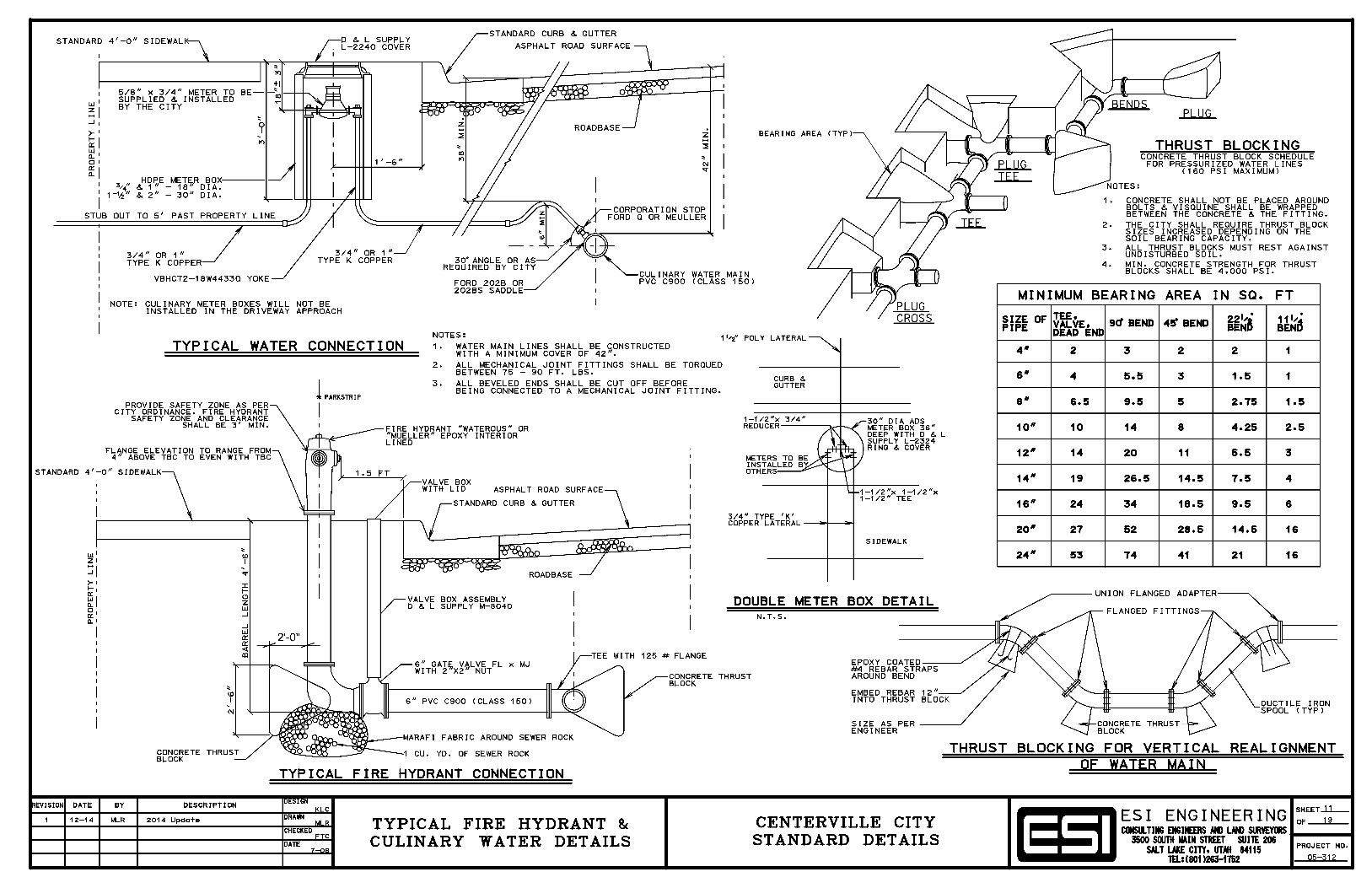
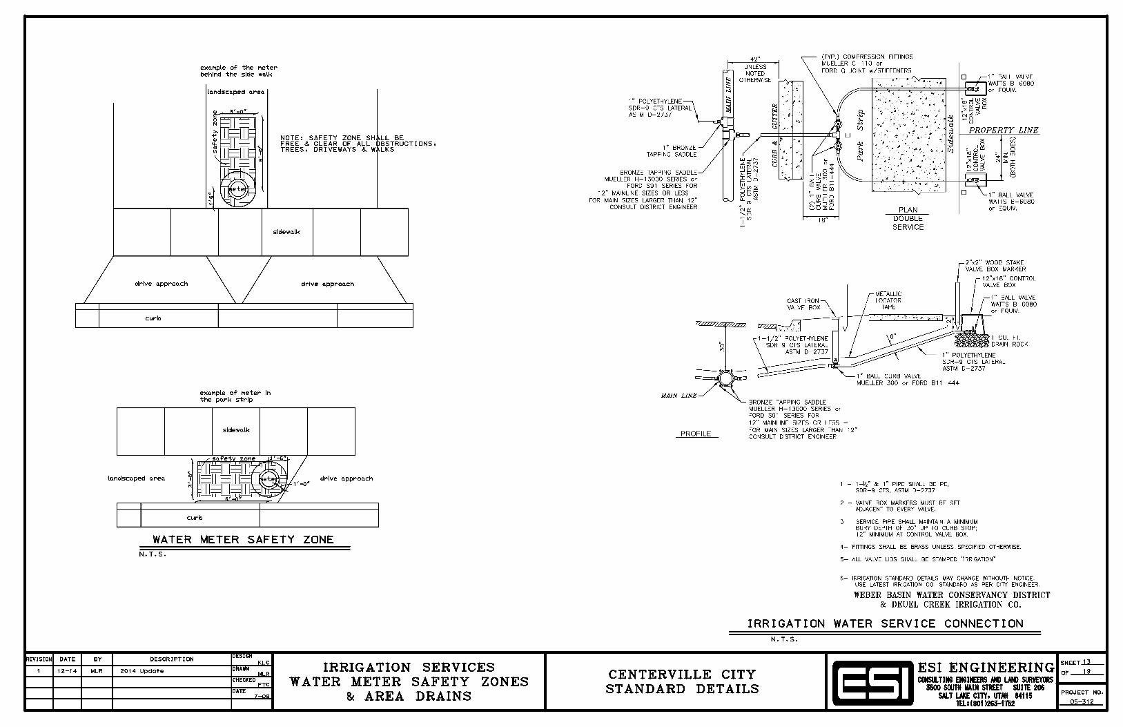
1.5 UTILITY PIPE WITHIN RIGHT-OF-WAYA. Use Class III reinforced concrete pipe for storm drains.B. Use Class 150 PVC AWWA C900 for culinary water lines (also see 2.0)C. Use ASTM D 3034 PVC for sewer pipes and ASTM D 2729 for sub-drains.D. Use ASTM D 2855 for underground irrigation systems.
1.6 PAVING ASPHALTSA. Use AC-20-DM-3/4 (asphalt-aggregate mix shall be composed of AC-20 type and grade asphalt cement and DM-3/4 type and grade aggregate).B. Use Type III Slurry Seal. Apply crack seal and allow to dry before applying slurry seal.C. Temperature and moisture:
1. Apply when air and roadbed temperatures in the shade are 45 deg. F. and rising. 2. Do not apply if roadbed or air temperature is below 55 deg. F. and falling or if the
finished product will freeze before 24 hours. 3. Do not apply during rain, unsuitable weather, or if humidity prolongs curing.
1.7 UNTREATED BASE COURSE (ROAD BASE)
A. Properties - Use Aggregate Class A.
B. Gradation - Use Master Grading Band Limits “Grade - 1-1/2".
1.8 GRANULAR BACKFILL FOR STREET SUB-BASE
A. Classification A-1-a, AASHTO Soil Classification and ASTM D 3282.
B. Well graded.
C. Particle size; 4 inch maximum.
D. Material meets design CBR-value (ASTM D 1883) or R value (ASTM D 2844) for suitability of source, not for project control testing.
1.9 GRANULAR BACKFILL FOR TRENCHES
A. Classification A-1, AASHTO Soil Classification and ASTM D 3282.
B. Well graded.
C. Particle size; 2 inch maximum.
D. Material meets design CBR-value (ASTM D 1883) or R value (ASTM D 2844) for suitability of source, not for project control testing.
2.0 CULINARY WATER LINES
A. PVC Pipe - All water pipe shall be class 150 ring-tite, PVC 900, DR18unless otherwise specified. Pipe shall meet all A.W.W.A. requirements. All pipeshall have a minimum burst pressure of 755 PSI, shall have a molded bell andmeet the requirements of AWWA ASTMD-1 869, and shall not be bleached bysunlight.
B. Cast Iron Fittings - All fittings shall be made in strict accordance with ANSIA21 10: and A.W.W.A. spec C110-71. They shall be class 150 pipe, and tarcoated. All fittings need to be American made.
C. Tapping Sleeves - Must be all stainless steel; including the flange, must meetall AWWA specifications.
D. Fire Hydrants - Waterous Pace, Mueller Centurion, Clow Medallion will beaccepted. All hydrants will be flanged and, unless called out. Bottom shoe shallbe epoxy coated, inside and out. Pumper nozzle shall be 4 ½ and hose nozzlesshall be 2 ½. Color shall be red.
E. Service Saddled - Must be all brass. It must have two bands (band needs tobe all brass or stainless steel). The band needs to be molded for PVC. Theoutlets need to be iron pipe thread and need to meet all A.W.W.A. specifications. Reference: Ford 202B
F. Corporation Stop and Copper Tubing Fittings - Corporation stop, coupling,etc. need to be all compression and all brass, unless otherwise specified.
Reference: Ford Q, or Mueller. All fittings need to be American made.
G. Copper Setter - All copper setter yokes need to have duel check valves, 18"in high locking tab, compression, ball valve type, and need to be able to set " -¾" meter. Reference Ford VBHC 72 18W4433Q, and must have state approvedduel check valve. 1" VBHC 74 18W4444Q, 1 ½ VHH 76 18B1166, 2" VHH 7718B1177.
H. Meter Boxes - Must be all white plastic, 18" in diameter and 30" in heightfor ¾” line service. Must be all white plastic, 20" in diameter and 30" in heightfor 1” line service. Must be all white or black plastic, 30" in diameter and 30" inheight for 1 ½ and 2" service line.
I. Meter Box Lid - Must be cast iron cover 18" in diameter and have a standardwaterworks pentagon head made of all brass and must be all tar coated for ¾”service. 21" meter box lids for 1" lines. All lids must have a 2” knockout fortouch read meters. 18" Reference D&L L-2240, 21" Reference D&L L2244, 30"Reference D&L L2324.
J. Ductile Iron - All ductile water line Class 350 PSI with molded bell pipe shallmeet AWWA requirements.
K. Gate Valves - Shall meet all A.W.W.A. specifications, C 509. All valves
shall be resilient wedge. All valves need to have iron body, operating nut needsto be 2" square and the outside must be coated a minimum thickness of 4 millswith two part thermo setting epoxy coating. Must be all stainless steel bolts.
L. Copper Water Service - Must be type “K” copper.
M. High Density Polyethelene (HDPE) - Must mee the requirements of ASTMD2737, ASTM D2239, and AWWA C-901. Must have a 200 psi rating and mustbe copper tube size.
N. Valve Boxes - Must be 6" in diameter, tar coated , able to go 48" in depth,and be slide operational.
O. Flange Bolt Packs - All bolts and nuts need to be stainless steel.
Centerville City Standards 1 Section 01 42 19
SECTION 01 42 19
REFERENCES
PART 1 GENERAL
1.1 SECTION INCLUDES A. Acronyms used in Specifications for reference standards. B. Source of references. C. Applicability of referenced standards. D. Provision of referenced standards at site.
1.2 QUALITY ASSURANCE
A. For products or workmanship specified by trade association or government agency, comply with City requirements of the standard, except when more rigid requirements are specified or are required by applicable codes.
B. The latest edition of the standards and their supplements referenced as a part of any section are incorporated in that section to the extent specified therein. In any case of conflict, the requirements of the section shall prevail.
C. When required by individual specification section, obtain copy of standard. Maintain copy at job site during submittals, planning, and progress of the specific work, until Completion.
1.3 TRADE ASSOCIATIONS
A. The following acronyms or abbreviations referenced in Contract Documents are subject to change, and are the best known at date of this book's publishing.
AAMA American Architectural Manufacturer's Association, 2700 River Road, Suite118, Des Plaines, IL 60018.
AAN American Association of Nurserymen, Inc., 1250 I Street, NW., Suite 500,Washington DC 20005.
AASHTO American Association of State Highway and Transportation Officials, 444North Capitol Street, NW, Washington, DC 20001.
ACI American Concrete Institute, Box 19150, Reford Station, Detroit, MI 48219.
ACPA American Concrete Pipe Association, 8320 Old Courthouse Rd., Vienna, VA22180.
AGC Associated General Contractors of America,1957 E. Street, NW, Washington,DC 20006.
AI Asphalt Institute, Asphalt Institute Building, College Park, MD 20740.
Centerville City Standards 2 Section 01 42 19
AIA American Institute of Architects, 1735 New York Avenue, N.W., Washington, D.C. 20006-5292.
AISC American Institute of Steel Construction, 400 North. Michigan Ave., Chicago, IL 60611.
AMRL Aashto Materials Reference Library, 444 North Capitol Street, NW, Washington, DC 20001.
AISI American Iron Standards Institute, 1133 Fifteenth St., NW Washington, DC 20005.
ANSI American National Standards Institute, 1430 Broadway, New York, NY 10018.
APA American Plywood Association, P.O. Box 11700, Tacoma, WA 98411.
ASME American Society of Mechanical Engineers, 345 East 47th Street, New York, NY 10017.
ASPA American Sod Producers Association, Association Building, Ninth and Minnesota, Hastings, NE 68901.
ASTM American Society for Testing and Materials, 1916 Race Street, Philadelphia, PA 19103.
ATSSA American Traffic Safety Services Association, Inc., ATSSA Building, 5440 Jefferson Davis Highway, Fredericksburg, VA 22401.
AWPA American Wood-Preservers' Association, P.O. Box 849, Stevensville, MD 21666 AWPB American Wood-Preservers' Bureau,
P.O. Box 5283, Springfield, VA 22150. AWS American Welding Society, 350 Le Jeune Road, NW., Miami, FL 33125. AWWA American Water Works Association, 6666 West Quincy Avenue, Denver, CO 80235. BIA Brick Institute of America, 11490 Commerce Park Drive, Suite 300, Reston, VA 22091. CLFMI Chain Link Fence Manufacturers Institute, 1776 Massachusetts Avenue, N.W., Washington, DC 20036. CRSI Concrete Reinforcing Steel Institute, 933 Plum Grove Rd., Schaumburg, IL 60195. CSI The Construction Specifications Institute, 601 Madison Street, Alexandria, VA 22314-1791. EIA Electronic Industries Association, 2001 I Street, NW, Washington, DC 20037.
ICBO Workman Mill Road, Whittier, CA 90601. ICEA Insulated CableEngineer’s Association, P.O. Box 440, South, Yarmouth, MA02664
ICPI Interlocking Concrete Pavement Institute, 14444 Eye Street NW, Suite 700,Washington DC 20005-2210. www.icpi.org.
IMIAC International Masonry Industry All-Weather Council, International Masonry
Centerville City Standards 3 Section 01 42 19
Institute, 823 15th Street, N.W, Washington, DC 20005.
IMSA International Municipal Signal Association, P.O. Box 539, 1115 N. Main St.,Newark, NY 14513.
MBMA Metal Building Manufacturer's Association, 1230 Keith Building,Cleveland, OH 44115.
NAA National Arborist Association, 174 Rt. 101, Bedford, NH 03102.
NEC National Electric Code (from NFPA).
NEMA National Electrical Manufacturer's Association, 2101 L Street NW, Suite 300,Washington CD 20037.
N.F.P.A.National Forest Products Association, 1250 Connecticut Avenue, N.W.,Washington, DC 20036.
NFPA National Fire Protection Association, Batterymarch Park, Quincy, MA 02269.
NPCA National Precast Concrete Association, 1033 N. Meridian Street, Suite 272,Indianapolis, IN 46290
NSF National Sanitation Foundation, P.O. Box 1468, 3475 Plymouth Road,Ann Arbor, MI 48106.
PCA Portland Cement Association, 5420 Old Orchard Road, Skokie, IL 60077.
PCI Prestressed Concrete Institute, 175 W. Jackson Blvd., Chicago, IL 60604. PPI Plastic Pipe Institute. A Division of the Society of The Plastics Industry, Inc.,
355 Lexington Avenue, New York, N.Y. 10017.
S.D.I. Steel Door Institute, (c/o A.P. Wherry and Assoc. Inc.) 712 Lakewood CenterNorth, 14600 Detroit Ave, Cleveland, OH 44107.
SSPC Steel Structures Painting Council, 4400 Fifth Avenue, Pittsburgh, PA15213.
UBC Uniform Building Code (from ICBO).
UL Underwriters' Laboratories, Inc., 333 Pfingsten Road, Northbrook, IL60062.
WAQUC Western Alliance for Quality Transportation Construction.
WWPA Western Wood Products Association, 522 SW 5th Avenue, Yeon Building,Portland, OR 97204.
1.4 GOVERNMENT AGENCIES
A. The following acronyms or abbreviations indicate names of standards or specification producing agencies of the Federal and State Governments and are the best known at the publishing date of this document.
Centerville City Standards 4 Section 01 42 19
CE Corps of Engineers (U.S. Dept. of the Army) Chief of Engineers Referral, Washington, DC 20314.
CS Commercial Standard (U.S. Department of Commerce), Government PrintingOffice, Washington DC 20402.
DOT Department of Transportation, Federal Highway Administration, 400Seventh St., SW, Washington, DC 20590.
FS Federal Specification (General Services Administration), Specifications andConsumer Information, Distribution Section (WFSIS), 7th and D Street, SW,Washington, DC 20406.
MIL Military Standardization Documents (U.S. Dept. of Defence) Naval Publicationsand Forms Center, 5801 Tabor Avenue, Philadelphia, PA 19120.
NBS National Bureau of Standards (U.S. Department of Commerce),Gaithersburg, ND 20234.
PS Product Standard of NBS (U.S. Department of Commerce), GovernmentPrinting Office, Washington, DC 20402.
REA Rural Electrification Administration (U.S. Department of Agriculture) 14th St.and Independence Ave., SW, Washington, DC 20250.
UDOT Utah Department of Transportation, 4501 South 2700 West Street, Salt LakeCity, UT 84119.
USPS U.S. Postal Service, 475 L'Enfant Plaza, SW, Washington, DC 20260.
PART 2 PRODUCTS Not Used
PART 3 EXECUTION Not Used
END OF SECTION
Centerville City Standards 1 Section 01 43 00
SECTION 01 43 00
QUALITY ASSURANCE
PART 1 GENERAL
1.1 SECTION INCLUDES A. Developer’s Contractors quality assurance responsibilities.
1.2 WORKMANSHIP
A. Employ workers, Subcontractors and Suppliers who can produce the specified quality.
B. Supervise and manage workmanship and site conditions so work complies with Contract Document.
C. Comply with industry standards except where more restrictive tolerances, specified requirements, or precise workmanship is required.
1.3 INSTALLER
A. Qualifications: Employ installers with at least 3 years of successful installation experience on work similar to that required for Project.
B. Certificates: When required or request by City Engineer, submit copy of installer’s certifications issued by certification agency.
C. Field Services;
1. Examine areas and conditions under which materials and products are to be installed.
2. Do not proceed with work until unsatisfactory conditions have been corrected in a manner acceptable to installer.
3. Secure products in place with positive anchorage devices designed and sized to withstand stresses, vibration and racking.
4. Make new finishes match adjacent or old finishes.
1.4 MANUFACTURER
A. Qualifications: Employ firms regularly engaged in manufacture of materials and products of types and sizes required, whose products have been in satisfactory use in similar service for not less than 5 years.
B. Instructions: When required in individual section, submit manufacturer’s instructions in the quantity required for product data, delivery, handling, storage, assembly, installation, start-up, adjusting, balancing, and finishing as appropriate.
1. Should instructions conflict , request clarification before proceeding.
Centerville City Standards 2 Section 01 43 00
2. Require compliance with instructions in full detail, including each step in sequence.
C. Certificates: When required or request by City Engineer, prove that manufacturer’s
product meets or exceeds specified requirements.
1.5 MOCK-UPS
A. Erect field samples and mock-ups in location(s) acceptable to City Engineer.
B. Assemble and erect complete, with specified attachment and anchorage devices, flashings, seals, finishes, and similar items.
PART 2 PRODUCTS Not used
PART 3 EXECUTION Not used
END OF SECTION
Centerville City Standards 1 Section 01 55 26
SECTION 01 55 26
TRAFFIC CONTROL
PART 1 GENERAL 1.1 SECTION INCLUDES
A. Traffic control requirements.
1.2 REFERENCES A. ASTM D 4956: Retroreflective Sheeting for Traffic Control. B. Instructions to Flaggers. Publication of UDOT.
C. Work Zone Traffic Control Guide: Publication of the Utah LTAP Center.
D. MUTCD: Manual on Uniform Traffic Control Devices for Streets and Highways (MUTCD).
1.3 SUBMITTALS
A. Traffic control plan within 10 days of receiving the Notice of Intent to Award.
B. Flagger or traffic control technician certificates when requested by City Engineer.
1.4 TRAFFIC CONTROL PLAN
A. Create a traffic control plan using the following resources. Resolve discrepancies between resources in descending order shown.
1. MUTCD. 2. Work Zone Traffic Control Guide. 3. ATSSA.
B. Include the following documentation as part of the traffic control plan.
1. Written description of phasing. 2. Drawing showing phasing (if required for clarity). 3. Drawing showing placement of traffic control devices.
C. Show how to move pedestrians through or around the Work site.
D. Show how to handle signalized intersections.
E. Meet grade, slope and protection requirement of the Americans with Disabilities Act (ADA).
Centerville City Standards 22 Section 01 55 26
1.5 TRAFFIC CONTROL TECHNICIAN
A. Certified by ATSSA or AGC.
1.6 FLAGGER A. Certified by ATSSA, AGC or UDOT. B. Equipment:
1. 24” x 24” “Stop/Slow” sign. 2. 6” to 8” long red wand for night flagging. 3. Light plant for night flagging.
C. Clothing: 1. Clothed; full length pants and long or short sleeved shirt. 2. Hard toed shoes. 3. Orange, red-orange hardhat and vest. 4. Night clothing to be reflectorized.
PART 2 PRODUCTS
2.1 PAVEMENT MARKINGS, SIGNS, BARRICADES A. MUTCH.
B. Channelizing Devices: Crash worthy plastic cones, drums and barricades.
C. Reflective Sheeting: ASTM D 4956.
D. Pavement Markings: Section 32 17 23.
PART 3 EXECUTION
3.1 FLAGGING
A. MUTCD.
3.2 TRAFFIC CONTROL DEVICES
A. Install before work activities begin.
B. Maintain to ensure proper, continuous function.
C. Remove when no longer needed.
END OF SECTION
Centerville City Standards 1 Section 01 57 00
SECTION 01 57 00
TEMPORARY CONTROLS
PART 1 GENERAL
1.1 SECTION INCLUDES
A. Requirements for controlling surface and subsurface environmental conditions at the construction site, and related areas under the Developer's responsibility.
B. Requirements for removal of physical evidence of temporary controls upon completion of the Work.
PART 2 PRODUCTS
2.1 MATERIALS
A. Temporary Materials: Developer's choice.
PART 3 EXECUTION
3.1 NOISE CONTROL
A. Use equipment that is equipped with noise attenuation devises. Comply with local Laws and Regulations.
B. Control construction noise in residential areas from 9:00 pm to 6:00 am.
3.2 DUST AND MUD CONTROL
A. Provide suitable equipment to control dust or air pollution caused by construction operations.
B. Provide suitable mud and dirt containment, so Work site, access roadways and properties adjacent to the Work site are kept clean.
3.3 SURFACE WATER CONTROL
A. Control all on-site surface water. Provide proper drainage so flooding of the site or adjacent property does not occur.
B. Provide and maintain ample means and devices with which to promptly remove and properly dispose of all water entering the site.
C. Immediately prior to suspension of construction operations for any reason, provide proper and necessary drainage of Work site area.
Centerville City Standards 2 Section 01 57 00
D. Provide berms or channels as necessary to prevent flooding or saturation of Subgrade. Promptly remove all water collecting in depressions.
E. Dispose of water in a manner that will not cause damage to adjacent areas or facilities.
3.4 GROUND WATER CONTROL
A. Provide a dewatering system sufficient to maintain Excavations and foundations dry and free of water on a 24 hour basis.
B. Notify City Engineer, in writing, if groundwater conditions differ from conditions shown in the approved plans, or in any soil test data that has been supplied.
C. Remove all dewatering facilities when no longer required.
D. Dispose of water in a manner that will not cause damage to adjacent areas or facilities.
3.5 POLLUTION CONTROL
A. Soil: Prevent contamination of soil from discharge of noxious substances (including engine oils, fuels, lubricants, etc.) during construction operations. Excavate and legally dispose of any such contaminated soil off-site, and replace with acceptable compacted fill and topsoil.
B. Water: Prevent disposal of wastes, effluent, chemicals, or other such substances adjacent to or into streams, waterways, sanitary sewers, storm drains, or public waterways. Perform any emergency measures that may be required to contain any spillage.
C. Air: Control atmospheric pollutants.
3.6 EROSION CONTROL
A. Use measures such as berms, dikes, dams, sediment basins, fiber mat netting, gravel, mulches, slopes, drains and other erosion control devices or methods to prevent
erosion and sedimentation.
B. Provide construction and earthwork methods which control surface drainage from cut, fill, borrow, and waste disposal areas, to prevent erosion and sedimentation.
C. Inspect earthwork during execution to detect any evidence of the start of erosion. Apply corrective measures as required.
END OF SECTION
Centerville City Standards 1 Section 01 65 00
SECTION 01 65 00
PRODUCT DELIVERY AND HANDLING
PART 1 GENERAL
1.1 SECTION INCLUDES A. Basic requirements for product delivery and handling on site.
1.2 DELIVERY
A. Arrange for delivery of products in accordance with progress schedule to facilitate instruction prior to installation.
B. Coordinate deliveries to avoid conflict with work and conditions at site and:
1. Work of separate contractors, or Developer’s. 2. Limitations of storage space. 3. Developer's use of premises.
C. Deliver products in undamaged condition in original containers or packaging, with identifying labels for handling, storing, unpacking, protecting and installing intact and legible.
D. Partial deliveries of component parts of equipment shall be clearly marked to identify the equipment, to permit easy accumulation of parts and to facilitate
assembly.
E. Immediately upon delivery, inspect shipment to determine:
1. Quantities are correct. 2. Containers and packages are intact, labels are legible. 3. Products are properly protected and undamaged.
1.3 PRODUCT HANDLING
A. Schedule delivery to minimize long-term storage at the site and to prevent overcrowding of construction spaces.
B. Coordinate delivery with installation time to ensure minimum holding time for items that are hazardous, easily damaged, or sensitive to deterioration, theft and other losses.
C. Handle products to prevent bending or over-stressing.
D. Lift heavy components at designated lifting points.
E. Discard damaged products.
1.4 ACCESS
Centerville City Standards 2 Section 01 65 00
A. Identify access to the Developer's work and office area by use of signs so that agents, delivery trucks and other parties desiring to contact the Developer may
do so.
B. In security zones, prevent unauthorized personnel from proceeding outside of Developer’s work and office areas.
PART 2 PRODUCTS Not Used
PART 3 EXECUTION Not Used
END OF SECTION
Centerville City Standards 1 Section 01 66 00
SECTION 01 66 00
PRODUCT STORAGE AND PROTECTION
PART 1 GENERAL
1.1 SECTION INCLUDES
A. Storage, handling and protection of products to be incorporated in the Work.
1.2 SUBMITTALS
A. Submit a copy of written permission if property other than Developer's is used to store materials or equipment.
1.3 STORAGE
A. Store products immediately on delivery, per manufacturer's instructions, with seals and labels intact and legible.
B. Store products subject to damage by elements in weather-tight enclosures.
1. Maintain temperatures within ranges required by manufacturer's instructions. 2. Provide humidity control for sensitive products, as required by manufacturer's
instructions.3. Store unpacked products on shelves, in bins or in neat piles, accessible for
Inspection.C. Provide substantial platforms, blocking or skids to support fabricated products above
ground, to prevent soiling or staining. Cover products, subject to discoloration or deterioration from exposure to the elements, with impervious sheet coverings. Provide adequate ventilation to avoid condensation.
D. Store loose granular materials on solid surfaces to prevent mixing with foreign matter. Provide surface drainage to prevent flooding or ponding of rainwater. Prevent mixing with refuse or injurious materials. Do not store construction materials and equipment in municipal rights-of-way for more than 5 days.
E. Arrange storage in manner to provide easy access for Inspection.
1.4 STORAGE ON SIDEWALK, CURB AND GUTTER
A. Do not remove, block, or otherwise render sidewalks unusable by either the storage of construction equipment or materials or construction procedures used, unless a safe, usable, alternate walkway at least 4 feet wide is provided.
B. Maintain curb and gutter clean and clear of debris, dirt, or excavated materials at all times.
Centerville City Standards 2 Section 01 66 00
1.5 MAINTENANCE OF STORAGE
A. Maintain periodic system of Inspection of stored products on scheduled basis to assure that:
1. State of storage facilities is adequate to provide required conditions. 2. Required environmental conditions are maintained. 3. Surfaces of products exposed to elements are not adversely affected.
B. Any weathering of products, coatings and finishes is not acceptable.
1.6 STORAGE AREA RESTORATION
A. Remove all plant, equipment and stockpiles from the Work.
B. Restore all storage areas and service roads to prior condition.
1.7 PROTECTION
A. Installed Product: Provide protection of installed products to prevent damage from subsequent operations. Remove when no longer needed, prior to completion and acceptance of Work.
B. Finished Surfaces: Provide coverings to protect finished surfaces from damage.
1. Cover projections, wall corners, jambs, sills and soffits of openings, in areas used for traffic and for passage of products in subsequent work.
2. Protect finished floors and stairs from dirt and damage. a. In areas subject to foot traffic, secure heavy paper, sheet goods, or other
materials in place. b. For movement of heavy products, lay planking or similar materials in place. c. For storage of products, lay tight wood sheathing in place. d. Cover walls and floor of elevator cars, and unprotected surfaces of car doors
when used by construction personnel. C. Waterproofed and roofed surfaces:
1. Prohibit use of surfaces for traffic of any kind, and for storage of any products. 2. When some activity must take place in order to carry out the Work, obtain
recommendations of Supplier and installer for protection of surface. a. Install recommended protection and remove on completion of that activity.
b. Restrict use of adjacent unprotected areas. D. Security: Provide security for materials, equipment and tools.
1.8 PROTECTION OF LAWNS AND LANDSCAPING
A. Protect planted lawn and landscaped areas from pedestrian and vehicular traffic.
END OF SECTION
1 Section 02 41 13
SECTION 02 41 13
SELECTIVE SITE DEMOLITION
PART 1 GENERAL
1.1 SECTION INCLUDES A. Demolition of structural and utility items on site. B. Salvage.
1.3 RELATED WORK A. Demolition of Pavements, sidewalks, Driveway Approaches, curbs, gutters,
Section 02 41 14. B. Existing pipelines not to be salvaged are considered a part of excavation work, Section
31 23 16. C. For use of explosives in the Work; Section 31 23 17.
1.4 SITE CONDITIONS A. Protect structures to be removed and their contents from vandalism and theft.
PART 2 PRODUCTS Not Used
PART 3 EXECUTION
3.1 PREPARATION
A. Review all work procedures with City Engineer.
B. Locate and preserve all active utilities which are to remain in service.
3.2 PROTECTION
A. Avoid or minimize damage to tree roots. Roots provide anchorage, storage of energy, and absorption and conduction of water and mineral elements. Loss of root connection affects health and stability of tree and safety of people and property.
B. Provide certified arborist observation of root cuts larger than 4 inches diameter. Notify City Engineer of such root cut.
3.3 STRUCTURE DEMOLITION
A. Remove structures and incidentals such as but not limited to foundations, sidewalks, Pavement slabs, fences and outbuildings.
2 Section 02 41 13
B. Remove foundation walls at least 2 feet below the finished grade or 2 feet below the natural ground surface. Remove floor slab or break it into pieces no larger than 3 feet square.
C. Backfilling and compaction of Excavations for structures, Section 31 23 23.
D. Building components, Section 02 41 19.
3.4 PIPELINE DEMOLITION
A. Salvaging Pipe: Do not damage.
B. Plugs: Plug disconnected pipe lines near the right-of-way line with a water-tight concrete plug extending into the remaining pipe at least 2 feet.
C. Service Laterals: Excavate and shut off the corporation stop. Disconnect.
3.5 BRIDGE AND ABUTMENT DEMOLITION
A. Remove existing bridges and abutments indicated.
B. Remove structures so that no remaining portion is closer than 3 feet to any water course or closer than 2 feet to the Subgrade and Embankment surface, or within 2 feet of the natural ground surface.
C. Remove structures so that compacted backfill can be provided as required in backfilling operation, Section 31 23 23.
3.6 BURIED FUEL TANK DEMOLITION
A. Remove buried fuel storage tanks and dispose of tank contents in accordance with Laws and Regulations.
B. Do not spill fuel on Subgrade.
C. Comply with the local authority having jurisdiction over fuel tank removals.
3.7 MISCELLANEOUS DEMOLITION
A. Remove miscellaneous structures and obstructions or cover them with backfill if the result meets the following requirements.
1. Backfill is stable. 2. Burial does not interfere with construction. 3. Permission to do so is obtained from the City Engineer. 4. No remaining portion is within 2 feet of the final ground surface contours.
3.8 SALVAGE A. Salvage designated equipment and materials.
END OF SECTION
C e n t e r v i l l e C i t y S t andards 1 Section 02 41 14
SECTION 02 41 14
PAVEMENT REMOVAL
PART 1 GENERAL
1.1 SECTION INCLUDES A. Removal of roadway Pavement. B. Milling roadway Pavement.
C. Removal of curb, gutter, sidewalk, driveway approach, waterway, or similar flatwork.
D. Disposal of removed materials.
1.2 RELATED WORK
A. Demolition of structures and utilities.
1.3 DEFINITIONS
A. ADA: Americans with Disabilities Act.
1.4 SUBMITTALS
A. Traffic control plan, Section 01 55 26.
1.5 SITE CONDITIONS
A. Control dust, Section 01 57 00.
PART 2 PRODUCTS Not Used
PART 3 EXECUTION
3.1 PREPARATION
A. General
1. Preserve all active utilities. 2. Notify neighborhood of day and time of operation. 3. Mark existing utilities on redline drawings.
B. Traffic Control: Provide worker and public safety, Section 01 55 26.
C. Tree Roots:
1. Avoid or minimize damage to tree roots. Roots provide anchorage, storage of energy,and absorption and conduction of water and mineral elements. Loss of root connection
C e n t e r v i l l e C i t y S t andards 2 Section 02 41 14
affects health and stability of tree and safety of people and property.
2. Provide certified arborist observation of root cuts larger than 4 inches diameter.Notify City Engineer of such root cut.
D. Existing Surfaces:
1. Do not damage adjacent concrete surfaces that are not scheduled for removal. 2. Use rubber cleats or Pavement pads when operating backhoes, outriggers, track
equipment, or any other equipment on or crossing paved surfaces. 3. Restore paved surfaces that are damaged by removal operations. Match the existing Pavement surface plus 1 inch.
3.2 SAW-CUT PEDESTRIAN TRIP HAZARDS
A. Make saw cuts 1:8 slope measured to grade.
B. Eliminate trip hazards across the full width of the hazard.
3.3 SAW-CUT CURB HORIZONTALLY A. Saw cut curbs for ADA ramps at 1:12 slope. No trip hazard at gutter flow line. B. Saw cut curbs for flares:
1.1:4 slope measured to grade, or 2. 1:12 slope measured horizontally when complying with ADA.
3.4 REMOVE PORTLAND CEMENT CONCRETE
A. Remove concrete to the nearest expansion joint or vertical saw cut. B. Make concrete cuts straight, vertical to the surface, true, full depth. C. DO NOT use machine mounted impact hammers.
3.5 REMOVE ASPHALT CONCRETE A. Saw cut full depth and remove Pavement.
B. When asphalt concrete overlays Portland cement concrete Pavements do not use a machinemounted impact hammer.
3.6 MILLING
A. Machine: 1. Equipped to prevent air pollution. 2. Equipped with a system to control slope of mill cut.
B. Tolerances:
1. Milling Depth: As indicated plus or minus 10 percent not uniformly high or uniformly low.
2. Striation Texture: Uniform, discontinuous, longitudinal, 3/16 inch deep maximum, 3/4 inch center to center.
3. Smoothness: Plus or minus 5/16 inch in 25 feet.
C e n t e r v i l l e C i t y S t andards 3 Section 02 41 14
4. Cross Slope: Plus or minus 1/4 inch in 10 feet. C. Performance:
1. Lower utility frames, covers, and other Street Fixtures. 2. Mill surfaces to the depth shown on the Drawings or indicated by City Engineer.
Do not disfigure adjacent work or existing surface improvements. 3. If milling exposes smooth underlying Pavement surfaces, mill the smooth surfaces
to make them rough. 4. Mill off material if it ponds water or if it has been damaged by water.
5. Where vehicles or pedestrians must pass over milled edges provide safe temporary ramps suitable to speed of user vehicles (or suitable for wheel chair user needs).
6. Remove excess material and clean milled surfaces. 7. If work equipment is removed from the milling site and milled surface awaits
further work, provide appropriate traffic control and cleaning.
3.7 GRINDING
A. Machine:
1. Cutting head 36 inches wide minimum. 2. 50 to 60 diamond blades per foot of head.
B. Preparation:
1. Control traffic. 2. Provide water truck, waste truck, and other support machinery. 3. Mark areas to be ground.
C. Tolerances:
1. 1/4 inch lip transverse to the direction of vehicular travel. Potential for ponding not allowed.
2. 1/8 inch lip (or dent) parallel to direction of vehicular travel. 3. Taper ground areas from the lane/shoulder line into the shoulder area at 1/4 inch
per foot. D. Performance:
1. Skid resistance of final ground surface must be comparable to adjacent sections not requiring corrective work.
2. Surface treatment of ground areas. a. Asphalt Concrete: Asphalt tack coat and sand blotter, Section 32 12 14. b. Hydraulic Concrete: Water repellant, Section 07 19 00. 3. Waste grindings legally. 4. Protect downstream fish habitat.
3.8 CLEANING A. Remove all debris and concrete dust. Clean surrounding rails, sidewalks, Driveways, landscaping and other objects in vicinity of work.
END OF SECTION
Centerville City Standards 1 Section 02 41 15
SECTION 02 41 15
PAVEMENT PULVERIZING
PART 1 GENERAL
1.1 SECTION INCLUDES A. Full depth reclamation. B. Stabilizer selection guide.
1.2 REFERENCES
A. ASTM C 136: Standard Method for Sieve Analysis of Fine and Coarse Aggregates.
B. ASTM C 150: Standard Specification for Portland Cement.
C. ASTM D 558: Standard Test Methods for Moisture-Density Relations of Soil-CementMixtures.
D. ASTM C 595: Standard Specifications for Blended Hydraulic Cement.
E. ASTM C 618: Standard Specification for Fly Ash and Raw or Calcined Natural Pozzolanfor Use as a Mineral Admixture in Portland Cement Concrete.
F. ASTM D 2922: Standard Test Methods for Density of Soil and Soil-Aggregate in Placeby Nuclear Methods (Shallow Depth).
G. ASTM D 4318: Standard Test Method for Liquid Limit, Plastic Limit, and PlasticityIndex of Soils.
H. ASTM D 4832: Standard Test Method for Preparation and Testing of Soil-CementSlurry Test Cylinders.
1.3 SUBMITTALS
A. List of equipment to be used.
B. Mix design showing percentage and quantity of stabilizer needed.
C. Traffic control plan; Section 01 55 26.
1.4 SITE CONDITIONS
A. Section 01 57 00; control dust.
1.5 ACCEPTANCE
A. Gradation: Random measure.
B. Depth: Random measure each 1,000 square yards.
Centerville City Specifications 2 Section 02 41 15
C. Density: Nuclear gage or proof roll.
D. Quantity of stabilizer added matches submittal data.
PART 2 PRODUCTS
2.1. TACK COAT CURING COMPOUND A. Cationic or anionic emulsified asphalt, Section 32 12 03.
2.2 STABILIZER A. Cement:
1. Type I or II, ASTM C 150, or 2. Type IP or IS; ASTM C 595.
B. Aggregate: Gravel, untreated base course, crushed Portland cement concrete.
C. Chemical Stabilizer: Use type allowed by City Engineer.
2.3 MIX DESIGN
A. Gradation ASTM C 136.
Sieve Percent Passing by Weight3" 1003" 85 to 95
No. 4 45 maximum
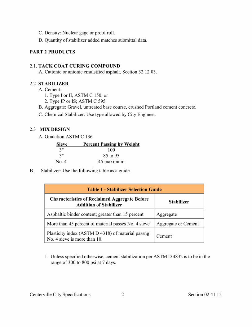
B. Stabilizer: Use the following table as a guide.
Table 1 - Stabilizer Selection Guide
Characteristics of Reclaimed Aggregate BeforeAddition of Stabilizer
Stabilizer
Asphaltic binder content; greater than 15 percent Aggregate
More than 45 percent of material passes No. 4 sieve Aggregate or Cement
Plasticity index (ASTM D 4318) of material passngNo. 4 sieve is more than 10.
Cement
1. Unless specified otherwise, cement stabilization per ASTM D 4832 is to be in therange of 300 to 800 psi at 7 days.
Centerville City Standards 3 Section 02 41 15
PART 3 EXECUTION
3.1 CONSTRUCTION EQUIPMENT
A. Capable of cutting to the required depth, pulverizing, and sizing the material.
3.2 PREPARATION
A. Identify location of all buried utilities.
B. Notify neighborhood of day and time of operation.
C. Set traffic control devices. D. Install invert covers. E. Lower Street Fixtures. F. Determine need for stabilizer.
3.3 CONSTRUCTION
A. Pulverize full depth. Do not remove excess material until full depth pulverizing is complete.
B. Remove excess material.
C. Pulverize a second time if stabilizer is required.
D. Shape, grade, roll, compact.
E. Cure stabilized material with water or asphalt tack coat.
3.4 FIELD QUALITY CONTROL
A. Reclaimed Aggregate: 95 percent minimum compaction using
1. Optimum water content and maximum density, ASTM D 558, and 2. Nuclear gage shallow depth, ASTM D 2922.
B. Stabilized Reclaimed Aggregate: Proof roll (prior to cement set).
3.5 REPAIR
A. Repair surface irregularities.
B. Seal cracks in cured stabilized material.
END OF SECTION
Centerville City Standards 1 Section 03 11 00
SECTION 03 11 00
CONCRETE FORMING
PART 1 GENERAL
1.1 SECTION INCLUDES A. Formwork for cast-in-place concrete. B. Openings in formwork for other affected work. C. Form accessories such as snap ties, bracing, etc. D. Stripping formwork.
1.2 REFERENCES A. ACI 347: Recommended Practice for Concrete Formwork.
1.3 DEFINITIONS A. Shoring: The activity to support formwork.
B. Reshoring: The activity to reduce the amount of formwork supporting concrete elements. As concrete sets and strength increases, less need for formwork occurs gradually until concrete becomes free standing.
1.4 SUBMITTALS
A. Shop Drawings: Fabrication and erection drawings of forms for specific finished concrete surfaces, as indicated. Show general construction of forms, jointing, special joints or reveals, location and pattern of form tie placement, and other items affecting exposed concrete visibility.
B. Form Release Agent: Where concrete surfaces are scheduled to receive special finishes or applied coverings which may be affected by agent submit manufacturer's instructions for use of agent.
1.5 QUALITY ASSURANCE
A. Designer's Qualifications: Structural professional engineer who complies with Utah licensing law, has experience in concrete formwork, and is acceptable to the authority having jurisdiction.
B. Design Forms:
1. With sufficient strength to maintain finished tolerances indicated in Section 03 35 00, to support loads, pressures, and allowable stresses as outlined in ACI 347 and
for design considerations such as wind loads, allowable stresses, and other applicable requirements of local Laws and Regulations.
2. To permit easy removal.
Centerville City Standards 2 Section 03 11 00
3. For required finishes. C. The design, engineering, and construction of formwork is Developer's responsibility.
1.6 JOB CONDITIONS
A. For reference purposes, establish and maintain sufficient control points and bench marks to check tolerances. Maintain in an undisturbed condition and until final completion and acceptance of Work.
B. Regardless of tolerances specified, allow no portion of Work to extend beyond legal boundaries.
1.7 FIELD SAMPLES
A. Construct and erect sample formwork panel for architectural concrete surfaces receiving special treatment or finish as a result of formwork. Formwork to include vertical and horizontal form joints and typical rustication joints when required.
B. Size panel to indicate special treatment or finish required, including form release agent.
C. Remove formwork after casting concrete.
1.8 ACCEPTANCE
A. Secure City Engineer's review of form layout for concrete flat work.
PART 2 PRODUCTS
2.1 FORM MATERIALS
A. Faced with material which will produce smooth and uniform texture on concrete, unless indicated otherwise.
B. Arrange facing material orderly and symmetrical, keeping number of seams to a minimum.
C. Do not use material with raised grain, patches, or other defects which will impair texture of concrete surface.
2.2 FORMWORK ACCESSORIES
A. Form Ties:
1. Use ties constructed so that end fasteners can be removed without spalling concrete faces.
2. After end fasteners of ties have been removed, embedded portion of ties are to
Centerville City Standards 3 Section 03 11 00
terminate not less than 2 times the diameter or thickness of the fasteners from formed faces of concrete, but in no case greater than 3/4 inch.
3. When the formed face on concrete is not exposed, form ties may be cut off flush with formed surfaces. Use ties with 3/4 inch diameter cones on both ends or an approved equal for water retaining structures.
B. Premolded Expansion Joint Filler: Unless indicated otherwise, provide Type F1, Section 32 13 73.
C. Form Release Agent: Colorless material which will not stain concrete, absorb moisture, impair natural bonding or color characteristics of concrete. To prevent contamination, agents used on potable water structures are subject to review by City Engineer prior to use.
D. Fillets for Chamfered Corners: Wood strips 1 inch x 1 inch size, maximum length possible.
PART 3 EXECUTION
3.1 INSPECTION
A. Verify lines, levels, and measurements before proceeding with formwork.
3.2 FORM CONSTRUCTION
A. Make forms sufficiently tight to prevent loss of concrete.
B. Unless indicated otherwise, place chamfer strips in corners of forms to produce beveled edges on permanently exposed exterior corners.
C. To maintain specified finish tolerances, camber formwork to compensate for anticipated deflections.
D. Provide positive means of adjustment using wedges, jacks, Shores, and struts to take up all settlement during concrete placing operation.
E. Provide temporary ports in formwork to facilitate cleaning and Inspection. Locate openings at bottom of forms to allow flushing water to drain.
F. At construction joints, overlap forms over hardened concrete at least 6 inches. Hold
forms against hardened concrete to prevent offsets or loss of mortar at construction
joint and to maintain true surface.
G. Construct wood forms for wall openings to facilitate loosening, or counteract swelling.
H. Fasten wedges used for final adjustment of forms prior to concrete placement in position after final check.
I. Anchor formwork to Shores, supporting surfaces or members to prevent upward or
Centerville City Standards 4 Section 03 11 00
lateral movement and deflection of any part of formwork system during concrete placement.
J. Provide runways for moving equipment with struts or legs, supported directly on formwork or structural member without resting on reinforcing.
K. Position expansion joint material and other embedded items accurately and support to prevent displacement.
L. To prevent entry of concrete, fill voids in sleeves, inserts, and anchor slots temporarily with readily removable material.
M. For architectural concrete, limit deflection of facing materials between studs as
well as deflection of studs and walers to 0.0025 times span.
N. For underground concrete work, do not use soil walls for forming unless authorized by City Engineer.
3.3 INSERTS, EMBEDDED PARTS, AND OPENINGS
A. Provide formed openings for elements embedded in or passing through concrete.
B. Coordinate work of other sections for the forming and setting of openings, slots, recesses, chases, sleeves, bolts, anchors, and other inserts.
C. Install accessories per manufacturer's instructions. Ensure items are not disturbed during concrete placement.
3.4 FORM FINISHES
A. Use forms with smooth rubbed, scrubbed, sand floated finishes that meet ACI 347 unless indicated otherwise.
B. For As-cast Finishes:
1. Install form panels in orderly arrangement with joints planned in approved relation to building elements.
2. Where panel joints are recessed or otherwise emphasized, locate form ties within joints, not within panel areas.
3. Where an as-cast finish is required, no grouting will be permitted in the finishing operation.
C. Textured Finishes: As indicated.
3.5 APPLICATION OF FORM RELEASE AGENT
A. Apply form release agent on formwork per manufacturer's instructions. Apply prior to placing reinforcing steel, anchoring devices, and embedded items.
3.6 FORM REMOVAL
Centerville City Standards 5 Section 03 11 00
A. Do not pry against face of concrete. Use only wooden wedges. B. When repair of surface defects or finishing is required at an early age, remove forms as soon as concrete has hardened sufficiently to resist damage from removal operations. C. Remove top forms on sloping surfaces of concrete as soon as concrete has attained sufficient stiffness to prevent sagging. Perform needed repairs or treatment required on such sloping surfaces at once, followed by specified curing. D. Loosen wood forms for wall openings as soon as it can be accomplished without damage to concrete. E. Formwork for columns, walls, sides of beams, and other members not supporting the weight of concrete may be removed as soon as the concrete has hardened sufficiently to resist damage from removal. F. Where no Reshoring is planned, leave forms and Shoring used to support weight of concrete in beams, slabs, and other concrete members in place until concrete has attained its specified strength. G. Where Reshoring is planned, supporting formwork may be removed when concrete has reached 70 percent of specified strength, provided Reshoring is installed immediately. H. When Shores and other vertical supports are so arranged that non-load carrying, form-facing material may be removed without loosening or disturbing Shores and supports, facing material may be removed at an earlier age as directed.
3.7 RESHORING A. When Reshoring is permitted or required, plan operations in advance and obtain Approval. B. During Reshoring do not subject concrete in beam, slab, column, or any other structural member to combined dead and construction loads and live loads in excess of loads permitted for developed concrete strength at time of Reshoring. C. Place Reshores as soon as practical after stripping operations are complete, but in no Tighten Reshores to carry required loads without over-stressing. E. Leave Reshores in place until the concrete being supported has reached its specified strength. F. For floors supporting Shores under newly placed concrete, level original supporting Shore or Reshore. 1. Reshoring system shall have a capacity to resist anticipated loads in all cases equal to at least 1/2 the capacity of the Shoring system. 2. Unless otherwise specified locate Reshores directly under a Shore. 3. In multistory buildings, extend Reshoring through a sufficient number of stories to distribute the weight of newly placed concrete, forms, and construction live loads in such a manner that design loads of floors and supporting Shores are not exceeded. G. Design, engineering, and construction of Shoring and Reshoring is the responsibility of the Developer.
Centerville City Standards 6 Section 03 11 00
3.8 REMOVAL STRENGTH A. When removal of formwork or Reshoring is based on concrete reaching a specified strength, it shall be assumed that concrete has reached this strength when either of the following conditions has been met:
1. When test cylinders, field cured along with the concrete they represent, have reached the specified strength. 2. When concrete has been cured per Section 03 39 00 for the same length of time as the site-cured cylinders that reached specified strength. Determine the length of time the concrete has been cured in the structure by cumulative number of days or fractions thereof, not necessarily consecutive, during which the air temperature is above 50 deg. F. and concrete has been damp or sealed from evaporation and loss of moisture.
3.9 REUSE OF FORMS A. Do not reuse forms if there is any evidence of surface wear or defect which would
impair quality of concrete surface.
B. Thoroughly clean and properly coat forms before reuse.
3.10 FIELD QUALITY CONTROL
A. Before commencing a pour, verify connections, form alignment, ties, inserts and Shoring are placed and secure.
B. Observe formwork continuously while concrete is being placed to verify that the forms are plumb and there are no deviations from desired elevation, alignment, or camber.
C. If during construction any weakness develops and false-work shows undue settlement or discoloration, stop work, remove affected construction if permanently damaged, and strengthen false-work.
END OF SECTION
Centerville City Standards Section 03 15 151
SECTION 03 15 15
EXPANSION AND CONTRACTION JOINTS
PART 1 GENERAL
1.1 SECTION INCLUDES A. Joints and joint sealants in horizontal traffic surfaces for cast-in-place concrete sidewalks, curb, gutter and pavement slabs.
1.2 REFERENCESA. ASTM C 920: Standard Specification for Elastomeric Joint Sealants.B. ASTM D 545: Standard Method of Testing Preformed Expansion Joint Fillers for
Concrete Construction (Nonextruding and Resilient Types).C. ASTM D 994: Standard Specification for Preformed Expansion Joint Filler for Concrete
(Bituminous Type).D. ASTM D 1056: Standard Specification for Flexible Cellular Materials - Sponge or
Expanded Rubber.E. ASTM D 1190: Standard Specification for Concrete Joint Sealer, Hot-Poured Elastic
Type.F. ASTM D 1191: Standard Method for Testing Concrete Joint Sealers.G. ASTM D 1751: Standard Specification for Preformed Expansion Joint Filler for
Concrete Paving and Structural Construction (Nonextruding and Resilient Bituminous Types).
H. ASTM D 1752: Standard Specification for Preformed Sponge Rubber and Cork Expansion Joint Fillers for Concrete Paving and Structural Construction.
I. ASTM D 1850: Standard Specification for Concrete Joint Sealer, Cold-Application Type.J. ASTM D 1851: Standard Methods of Testing Concrete Joint Sealers, Cold-Application
Type.K. ASTM D 2240: Standard Test Method for Rubber Property - Durometer Hardness.L. ASTM D 2628: Standard Specification for Preformed Polychloroprene Elastomeric Joint
Seals for Concrete Pavements.M. ASTM D 3405: Standard Specification for Joint Sealants, Hot-Poured, For Concrete and
Asphalt Pavements.N. ASTM D 3406: Standard Specification for Joint Sealant, Hot-Applied, Elastomeric-
Type, for Portland Cement Concrete Pavements.O. ASTM D 3407: Standard Method of Testing Joint Sealants, Hot-Poured, For Concrete
and Asphalt Pavements.P. ASTM D 3408: Standard Methods of Testing Joint Sealants, Hot-Poured, Elastomeric-
Type, for Portland Cement Concrete Pavements.Q. ASTM D 3542: Standard Specification for Preformed Polychloroprene Elastomeric Joint
Seals for Bridges.
Centerville City Standards Section 03 15 152
R. ASTM D 3569: Standard Specification for Joint Sealant, Hot-Applied, Elastomeric, Jet-Fuel-Resistant-Type for Portland Cement Concrete Pavements.
S. ASTM D 3581: Standard Specification for Joint Sealant, Hot-Poured, Jet-Fuel- Resistant Type, for Portland Cement Concrete and Tar-Concrete Pavements.
T. ASTM D 3582: Standard Method for Testing Joint Sealant, Hot-Poured, Jet-Fuel- Resistant Type, for Portland Cement Concrete and Tar-Concrete Pavements.
U. ASTM D 3583: Standard Methods of Testing Joint Sealant, Hot-Applied, Elastomeric- Type, for Portland Cement Concrete Pavements, or Joint Sealant, Hot-Applied, Elastomeric, Jet-Fuel-Resistant-Type, for Portland Cement Concrete Pavements.
V. FS SS-S-200: Sealants, Joint, Two Component, Jet-Blast Resistant, Cold-Applied, for Portland Cement Concrete Pavement.
1.3 SYSTEM PERFORMANCES A. Pavement joints include longitudinal and transverse expansion joints, contraction joints, construction joints, and crack control joints. B. Provide joint sealants that maintain watertight and airtight continuous seals.
1.4 SUBMITTALS A. Manufacturer's product data and samples for each joint sealant product required when requested by City Engineer.
1.5 QUALITY ASSURANCE A. Obtain joint sealing materials from a single manufacturer for each different product required.
1.6 DELIVERY, STORAGE, AND HANDLING A. Deliver materials to site in original unopened containers or bundles with labels identifying manufacturer, product name and designation, color, expiration period for use, pot life, cure time, and mixing instructions for multicomponent materials. B. Store and handle materials in compliance with manufacturer's recommendations to prevent deterioration; or damage due to moisture, high or low temperatures, contaminants, or other causes.
PART 2 PRODUCTS
2.1 GENERAL A. Compatibility: Provide joint fillers, sealant backings, sealants, and other related
materials that are compatible with one another and with joint substrate under conditions or service and application, as demonstrated by sealant manufacturer based on testing and field experience.
2.2 JOINT VOID - FORMER A. 1/4 depth of concrete structural section or as indicated.
Centerville City Standards Section 03 15 153
PART 3 EXECUTION
3.1 EXAMINATION A. Do not proceed with installation of joint sealants under unfavorable weather conditions. B. Install elastomeric sealants when temperature is stable in temperature range recommended by manufacturer for installation. C. Joint Substrate Conditions: Do not proceed with installation of joint sealers until contaminants capable of interfering with their adhesion are removed from joint substrate.
3.2 PREPARATION A. Clean, prepare and size joints in accordance with manufacturer's instructions. Remove any loose materials and other foreign matter which might impair adhesion of sealant. B. Verify that joint shaping materials and release tapes are compatible with sealant. C. Examine joint dimensions and size materials to achieve required width to depth ratio. D. Adjust joint depths to allow sealants to perform properly. E. Remove moisture on substrate. F. Bond Breaker Tape: Install where needed or required by manufacturer's recommendations to ensure that elastomeric sealants will perform properly.
3.3 JOINTS - GENERAL A. Construct all joints as follows:
1. At right angles to top surface of placement.2. Straight unless indicated otherwise.3. Before uncontrolled shrinkage cracking takes place.4. To prevent concrete edge slump.
3.4 EXPANSION JOINTS A. Do not extend reinforcement through an expansion joint. Place dowel mechanisms. B. Set joint fillers at proper depth or position in joint to coordinate with other work, including installation of bond breakers, backer rods, and sealants. Do not leave voids or gaps between ends of joint filler units. Secure holders and supports to prevent joint filler movement. C. Form transverse expansion joints at structures and concrete approaches using filler strips, backer rods and joint sealant. Support as needed with holders which will remain in place.
3.5 CONSTRUCTION JOINTS A. Construction joints (contact joints) are those made by placing concrete against cured concrete. When indicated construct construction joints with an indented keyway or tie-bar. B. Place tie-bar to eliminate edge slump. C. Maintain tie bars perpendicular to joint unless indicated otherwise. Before placing
Centerville City Standards Section 03 15 154
concrete in adjoining slab, straighten tie bars to proper position. If a "S" shape bend results from straightening, the offset from a straight line cannot exceed 0.1 feet.
3.6 CONTRACTION CRACK CONTROL JOINTS A. Joint spacing in feet shall not exceed twice the slab thickness in inches. Regardless of the thickness, joint spacing shall not exceed 15 feet. B. Contraction crack control joints are those made by sawing or tooling joints 1/4 depth of concrete structural section and 3/8 inch wide. Use of a plastic control joint-void former is acceptable in lieu of saw cutting or tooling. C. Make longitudinal joints the same dimension as transverse joints. D. Except where shown to be omitted or recommended to be omitted by sealant manufacturer, clean saw cut or tooled joint of loose debris, cement, dust, etc.; install 25 percent oversized backer rod to fit tightly in joint and seal joint.
3.7 JOINT SEALING A. Surface Preparation:
1. Remove oil, grease, wax, form-release-agents, curing compounds, bitumens, latency and old chalking material by sandblast, or water blast as recommended by manufacturer of sealant. Maximum sand blast angle, 25/ + 5.
2. Clean and dry with air blast. Do not contaminate air blast with oils or lubricants. 3. Remove frost and moisture in concrete joint substrate before commencing sealing.
B. Installation:1. Ensure that sealants are installed in uniform, continuous ribbons without gaps or air
pockets, with complete bonding of joint surfaces on opposite sides.2. Except as otherwise indicated, fill sealant rubbed flush with surface.3. Where horizontal joints are between a horizontal surface and vertical surface, fill joint
to from a slight cove so that joint will not trap moisture and dirt. C. Depths: Saw cut joints if necessary to provide the required sealant thickness and depth. Install sealant to depths indicated or, if not indicated, as recommended by sealant manufacturer, but within the following general limitations measured at center (thin) section of bead:
1. For sidewalks, pavements, and similar joints sealed with elastomeric sealants and subject to traffic and other abrasion and indentation exposures, fill joints to a depth equal to 75 percent of joint width, but neither more than 5/8 inch deep nor less than 3/8 inch deep.
2. For normal moving joints sealed with elastomeric sealants, but not subject to traffic, fill joints to a depth equal to 50 percent of joint width, but not more than 1/2 inch deep nor less than 1/4 inch deep. 3. For joints sealed with nonelastomeric sealants and caulking compounds, fill joints to a depth in range of 75 percent to 125 percent of joint width. D. Spillage: Do not allow poured sealant compound to overflow or spill onto adjoining surfaces or to migrate into voids of adjoining surfaces. Clean adjoining surfaces to eliminate evidence of spillage.
Centerville City Standards Section 03 15 155
E. Heating: Do no overheat hot-applied sealants. F. Edges: Unless indicated otherwise, recess exposed edges of gasket and exposed joint fillers slightly behind adjoining surfaces so compressed units will not protrude from joints.
3.8 CURE AND PROTECTION A. Cure sealants and caulking compounds in accordance with manufacturer's instructions and recommendations to obtain high early bond strength, internal cohesive strength and surface durability. B. Follow procedures required for cure and protection of joint sealants during construction period so they will be without deterioration or damage (other than normal wear and weathering) at time of Substantial Completion.
3.9 CLEANING A. Clean off excess sealants or sealant smears adjacent to joints as work progresses. Use methods and cleaning materials approved by manufacturers of joint sealant and of products in which joints occur. B. Remove protective coating and oil from metals with solvent recommended by the
sealant manufacturer.
3.10 PROTECTION A. Protect joint sealant during and after curing period from contact with contaminating substances or from damage resulting from deterioration or damage at time of Substantial Completion. B. If damage of deterioration occurs, cut out and remove damaged or deteriorated joint sealant immediately and reseal joints with new materials to produce joint sealer installations with repaired areas indistinguishable from original work.
END OF SECTION
Centerville City Standards 1 Section 03 20 00
SECTION 03 20 00
CONCRETE REINFORCING
PART 1 GENERAL
1.1 SECTION INCLUDES A. Reinforcing steel bars, wire fabric or rod mats for cast-in-place concrete.
B. Support chairs, bolsters, bar supports, and spacers for supporting reinforcement.
1.2 REFERENCES
A. AASHTO M 254: Standard Specification for Corrosion Resistant Coated DowelBars.
B. ACI 301: Specifications for Structural Concrete for Buildings.
C. ACI 315: Details and Detailing of Concrete Reinforcement.
D. ASTM A 82: Standard Specification for Steel Wire, Plain, for Concrete Reinforcement.
E. ASTM A 185: Standard Specification for Steel Welded Wire, Fabric, Plain, forConcrete Reinforcement.
F. ASTM A 615: Standard Specification for Deformed and Plain Billet-Steel Barsfor Concrete Reinforcement.
G. ASTM A 706: Standard Specification for Low-Alloy Steel Deformed Bars for ConcreteReinforcement.
H. ASTM C 1116: Standard Specification for Fiber-Reinforced Concrete and Shotcrete.
I. ASTM D 3963: Standard Specification for Epoxy-Coated Reinforcing Steel.
J. AWS D1.1: Structural Welding Code Steel.
K. AWS D1.4: Structural Welding Code Reinforcing Steel.
L. CRSI Document: Manual of Standard Practice.
1.3 SUBMITTALS
A. Manufacturer's Certificate: Submit mill test certificates of supplied concretereinforcement, indicating physical and chemical analysis.
B. Welder's certification.
C. Shop Drawings.
1. Indicate sizes, spacings, locations, and quantities of reinforcing steel, wire fabric, bending and cutting schedules, splicing, stirrup spacing, supporting, and spacing devices.
Centerville City Standards 2 Section 03 20 00
2. When required, prepare shop drawings by an engineer who complies with Utah licensing law and is acceptable to agency having jurisdiction.
1.4 QUALITY ASSURANCE
A. Perform concrete reinforcement work per CRSI Manual of Standard Practice.
B. Comply with ACI 301.
C. Welders: Certified to comply with AWS D1.1 or AWS D1.4 as applicable.
1.5 ACCEPTANCE
A. Unless specified otherwise, chairs for supporting reinforcement in flat slabs are spaced asfollows.
1. 3 feet maximum for No. 5 and smaller bars. 2. 5 feet maximum for bars larger than No. 5.
B. Dowels are placed on dowel baskets and properly aligned.
C. Epoxy and galvanized coatings are not chipped or cut. Ends of cut bars are epoxy coated orgalvanize painted prior to placement.
D. Minimum covering over reinforcement is as specified.
PART 2 PRODUCTS
2.1 MATERIALS A. Fiber Reinforcement: ASTM C 1116 glass. B. Reinforcing Steel: Deformed 60 ksi yield grade steel, ASTM A 615 and supplementary requirements S1 or ASTM A 706 for welding. C. Welded Steel Wire Fabric: ASTM A 185 plain type in flat sheets or coiled rolls. Dimensions of the mesh 4”x 4” or as indicated. D. Stirrups: ASTM A 82 steel. E. Plain Dowel Bars for Expansion Joints: Smooth grade 60 ksi yield grade steel, ASTM A 615, 1. Galvanized or epoxy coated in roadway Pavements. 2. Provide metal dowel cap at one end of dowel to permit longitudinal movement of dowel within concrete section. Design caps with 1 end closed. 3. Provide for movement equal to joint width plus 1/2 inch. 4. For load transfer bars, paint with 1 coat of paint conforming to AASHTO M 254 and coat 1/2 with grease. F. Coatings for Corrosion Protection: 1. Epoxy coat, ASTM D 3963. 2. Galvanized, Section 05 05 10.
Centerville City Standards 3 Section 03 20 00
2.2 ACCESSORY MATERIALS A. Tie Wire: Minimum 16 gage annealed type or an acceptable patented system. B. Chairs, Bolsters, Bar Supports, Spacers: Sized and shaped for strength and support of
reinforcement during installation and placement of concrete.
2.3 FABRICATION
A. Fabricate reinforcement, ACI 315 providing for concrete cover.
B. Locate reinforcing splices not indicated on Drawings at points of minimum stress.Indicate location of splices on shop drawings.
C. Weld reinforcing bars; with AWS D1.4.
PART 3 EXECUTION
3.1 PLACING
A. All reinforcement to be free of loose mill scale, loose or thick rust, dirt, paint, oil orgrease.
B. Place all reinforcement in the exact position indicated. With tie wire, tie bars together atall intersections except where spacing is less than 12 inches in each direction, in whichcase tie alternate intersections.
C. Maintain the distance from vertical forms and between layers of reinforcement bymeans of prefabricated chairs, ties, hangers, or other approved devices. Placing andfastening of reinforcement in each section of the Work must be approved beforeconcrete is placed.
D. Overlap sheets of metal mesh one square plus 6 inches to maintain a uniform strength.Securely fasten at the ends, edges, and supports to maintain clearances.
E. Flat Slab Work:
1. Support reinforcing steel of formed flat slabs with metal chairs, precast concrete blocks or other slab bolsters.
2. Size chairs or bolsters to position the steel in the exact location indicated. 3. Space chairs for supporting the top steel and bolsters for supporting the bottom steel
not more than 5 feet on centers in each direction. 4. Plastic or epoxy coat that portion of the metal support in contact with the forms to
prevent rust. 5. Tie down deck steel to beams or forms at regular intervals of not more than 5 feet on
centers along the beams or forms to prevent movement of the steel during concrete placement.
3.2 SPLICING
A. Furnish all reinforcement in the full lengths indicated unless otherwise permitted.
Centerville City Standards 4 Section 03 20 00
Splicing of bars, except where indicated is not permitted without written approval.Stagger splices where possible.
B. Unless indicated otherwise, overlap reinforcing bars a minimum of 30 diameters to makethe splice. In lapped splices, place the bars and wire to maintain the minimum distancefor clear spacing to the surface of the concrete.
C. Do not use lap splices on bars greater in diameter than No. 11 unless approved.
D. Weld reinforcing steel only if indicated or if authorized in writing. Weld in conformanceto AWS D1.4.
E. Do not bend reinforcement after embedding in hardened concrete.
F. Do not permit reinforcement or other embedded metal items bonded to the concrete, toextend continuously through any expansion joint, except dowels in floors bonded on onlyone side of joints.
3.3 PLACING EMBEDDED ITEMS
A. Place all sleeves, inserts, anchors and embedded items prior to concrete placement.Temporarily fill voids in embedded items to prevent entry of concrete.
B. Give all trades whose work is related to the concrete section ample notice andopportunity to introduce or furnish embedded items before concrete placement.
END OF SECTION
Centerville City Standards 1 Section 03 30 04
SECTION 03 30 04
CONCRETE
PART 1 GENERAL
1.1 SECTION INCLUDES A. Material requirements.
1.2 REFERENCES
A. ACI 211.1: Standard Practice for Selecting Proportions for Normal, Heavyweight, andMass Concrete.
B. ACI 211.2: Standard Practice for Selecting Proportions for Structural LightweightConcrete.
C. ACI 211.3: Standard Practice for Selecting Proportions for No-Slump Concrete.
D. ACI 214: Recommended Practice for Evaluation of Strength Test Results of Concrete.
E. ACI 301: Specifications for Structural Concrete for Buildings.
F. ACI 305: Hot Weather Concreting.
G. ACI 306: Cold Weather Concreting.
H. ACI 318: Building Code Requirements for Reinforced Concrete.
I. ASTM C 33: Standard Specification for Concrete Aggregates.
J. ASTM C 39: Standard Test Method for Compressive Strength of Cylindrical ConcreteSpecimens.
K. ASTM C 88: Standard Test Method for Soundness of Aggregates by Use of SodiumSulfate or Magnesium Sulfate.
L. ASTM C 94: Standard Specification for Ready-Mixed Concrete.
M. ASTM C 117: Standard Test Method for Material Finer than 75µ (No. 200) Sieve inMineral Aggregates by Washing.
N. ASTM C 138: Standard Test Method for Unit Weight, Yield, and Air Content(Gravimetric) of Concrete.
O ASTM C 143: Standard Test Method for Slump of Hydraulic-Cement Concrete.
P. ASTM C 150: Standard Specification for Portland Cement.
Q. ASTM C 172: Standard Method of Sampling Freshly Mixed Concrete
R. ASTM C 227: Standard Test Method for Potential Reactivity of Cement-AggregateCombinations (Mortar Bar Method).
S. ASTM C 231: Standard Test Method for Air Content of Freshly Mixed Concrete by thePressure Method.
Centerville City Standards 2 Section 03 30 04
T. ASTM C 260: Standard Specification for Air-Entraining Admixtures for Concrete. U. ASTM C 289: Standard Test Method for Potential Reactivity of Aggregates
(Chemical Method).
V. ASTM C 295: Standard Practice for Petrographic Examination of Aggregates forConcrete.
W. ASTM C 441: Standard Test Method for Effectiveness of Mineral Admixtures orGround Blast-Furnace Slag in Preventing Excessive Expansion of Concrete Due toThe Alkali-Silica Reaction.
X. ASTM C 494: Standard Specification for Chemical Admixtures for Concrete.
Y. ASTM C 595: Standard Specification for Blended Hydraulic Cements.
Z. ASTM C 618: Standard Specification for Fly Ash and Raw or Calcined NaturalPozzolan for Use as a Mineral Admixture in Portland Cement Concrete.
AA. ASTM C 1064: Standard Test Method for Temperature of Freshly Mixed PortlandCement Concrete.
BB. ASTM C 1116: Standard Specification for Fiber-Reinforced Concrete and Shot Crete.
CC. ASTM C 1157: Standard Performance Specification for BlendedHydraulic Cement.
DD. ASTM C 1240: Standard Specification for Use of Silica Fume as a Mineral Admixturein Hydraulic Cement Concrete, Mortar, and Grout.
EE. ASTM C 1260: Standard Test Method for Potential Alkali Reactivity of Aggregates(Mortar-Bar Method).
FF. ASTM C 1293: Standard Test Method for Concrete Aggregates by Determination ofLength Change of Concrete Due to Alkali-Silica Reaction.
GG. ASTM C 1567: Standard Test Method for Determining the Potential Alkali-SilicaReactivity of Combinations of Cementitious Materials and Aggregate (AcceleratedMortar-Bar Method).
HH. ASTM C 1602: Standard Specification for Mixing Water Used in The Production ofHydraulic Cement Concrete.
I I. ASTM D 1077: Standard Practice for Laboratories Testing Concrete and ConcreteAggregates for Use in Construction and Criteria for Laboratory Evaluation.
J J. ASTM STP 15-C: Manual on Quality Control of Materials.
1.3 SUBMITTALS
A. Quality Assurance: Submit names, certification levels, and years of experience oftesting agency’s laboratory and field technicians that are assigned to the Work. Verifylaboratory complies with ASTM and ACI standards.
B. Mix Design: Submit.
1. Date of mix design. If older than 365 days, recertify mix design.
Centerville City Standards 3 Section 03 30 04
2. Cement source, type and chemical composition. 3. Aggregate soundness and potential reactivity. 4. Average Strength (fcr), per quality control chart. 5. Allowable range of slump and air content. 6. Water cement ratio. 7. Proportions of materials in the mix. 8. Unit weight. 9. Analysis of water if water is not potable. 10.Mortar bar test results if a pozzolan is included in the mix. 11.Technical data sheets for additives to be used at the plant and at the job site.
Certify additives are compatible with each other. C. Pre-approved mix design, submit name and address of Supplier.
D. Before changing mix design, submit a new design and allow City Engineer 10 days toevaluate the changes.
E. Source Quality Control Inspections and Testing Report: If requested, submit reportdescribing Developer’s and Supplier’s quality control activities and test results.
1.4 QUALITY ASSURANCE
A. Use a laboratory that follows and complies with ASTM D 1077.
B. Reject concrete that does not meet requirements of this section.
C. Do not change material sources, type of cement, air-entraining agent, water reducingagent, other admixtures except as allowed by mix design.
D. Store bagged and bulk cement in weatherproof enclosures. Exclude moisture andcontaminants.
E. Prevent segregation and contamination of aggregate stockpiles.
F. Avoid contamination, evaporation, or damage to admixtures. Protect liquid admixturesfrom freezing.
G. Use of admixtures will not relax hot or cold weather placement requirements.
1.5 ACCEPTANCE
A. Materials:
1. At the Source: Verify aggregate gradation. Determine percent of combined aggregate passing No. 200 sieve.
2. At the Site: Verify mix identification, batch time, slump, air content, and temperature. 3. At the Laboratory: Verify strength in 28 days.
B. Placement:
1. Concrete in general, Section 03 30 10. 2. Pavement, Section 32 13 13 and 32 01 26. 3. Exterior flatwork, Section 32 16 13 or 32 16 14.
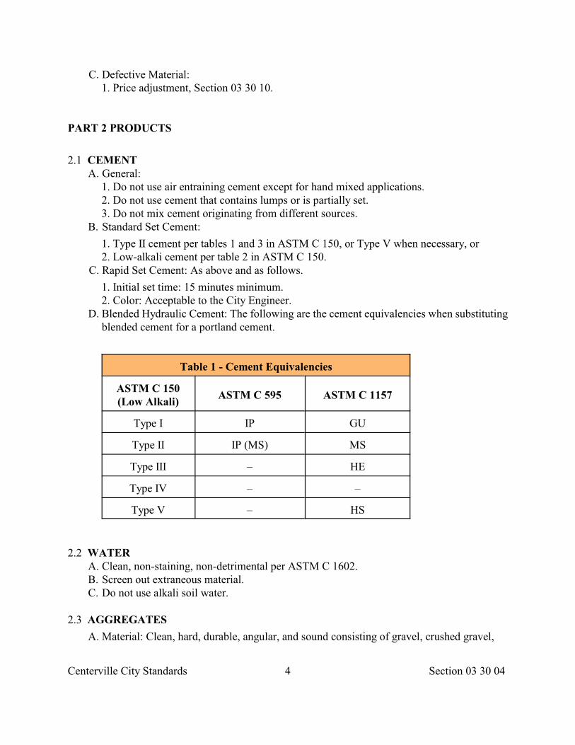
Centerville City Standards 4 Section 03 30 04
C. Defective Material: 1. Price adjustment, Section 03 30 10.
PART 2 PRODUCTS
2.1 CEMENT A. General:
1. Do not use air entraining cement except for hand mixed applications. 2. Do not use cement that contains lumps or is partially set. 3. Do not mix cement originating from different sources.
B. Standard Set Cement:
1. Type II cement per tables 1 and 3 in ASTM C 150, or Type V when necessary, or 2. Low-alkali cement per table 2 in ASTM C 150.
C. Rapid Set Cement: As above and as follows.
1. Initial set time: 15 minutes minimum. 2. Color: Acceptable to the City Engineer.
D. Blended Hydraulic Cement: The following are the cement equivalencies when substitutingblended cement for a portland cement.
Table 1 - Cement Equivalencies
ASTM C 150(Low Alkali)
ASTM C 595 ASTM C 1157
Type I IP GU
Type II IP (MS) MS
Type III – HE
Type IV – –
Type V – HS
2.2 WATER A. Clean, non-staining, non-detrimental per ASTM C 1602. B. Screen out extraneous material. C. Do not use alkali soil water.
2.3 AGGREGATES
A. Material: Clean, hard, durable, angular, and sound consisting of gravel, crushed gravel,
Centerville City Standards 5 Section 03 30 04
crushed stone, crushed concrete, slag, sand or combination.
B. Source: Use the following requirements to determine suitability of aggregate sourceand not for project control.
1. Deleterious Substances and Physical Properties:
a. Coarse Aggregate: Class designation 4S in table 3 in ASTM C 33. b. Fine Aggregate: Table 1 in ASTM C 33. Organic impurities producing a dark color
concrete may cause rejection. 2. Reactivity:
a. Average prism length change in 12 months in an unmodified ASTM C 1293 test is less than 0.04 percent, or
b. Average mortar bar length change at 16 days in an unmodified ASTM C 1260 test is less than 0.10 percent, or
c. Historical data acceptable to City Engineer, or d. Petrographic limits per ASTM C 295. 1) Optically strained, micro fractured, or
microcrystalline quartz: 5.0% maximum. 2) Chert or chalcedony: 3.0% maximum. 3) Tridymite or cristobalite: 1.0% maximum. 4) Opal: 0.5% maximum. 50 Natural volcanic glass volcanic rocks: 3.0% maximum 2.4 ADMIXTURES
A. Calcium Chloride: Not allowed.
B. Air Entrainment: ASTM C 260. For extrusion enhancement use nonvinsal resin.
C. Set Enhancement and Water Reducing Agents: ASTM C 494.
1. Type A: Water reducing. 2. Type B: Set retarding. 3. Type C: Set accelerating. 4. Type D: Water reducing and set retarding. 5. Type E: Water reducing and set accelerating. 6. Type F: High range water reducing (super plasticizer). * 7. Type G: High range water reducing and set retarding. *
* Keep the relative durability factor of water reducing additives not less than 90 and the chlorides content (as Cl ) not exceeding 1 percent by weight of the admixtures.
-
D. Pozzolan:
1. Natural or fly ash per ASTM C 618. 2. Silica fume per ASTM C 1240
E. Special Admixtures: Allowed if mix design submittal is accepted.
1. Lithium nitrate based solution for control of reactive aggregates. 2. Calcium nitrite based solution for corrosion protection of reinforced structures subject
to chloride-induced corrosion. 3. Shrinkage reducer for controlling drying shrinkage in concrete. 4. Viscosity modifier for enhancement of self consolidating concrete or for workability.
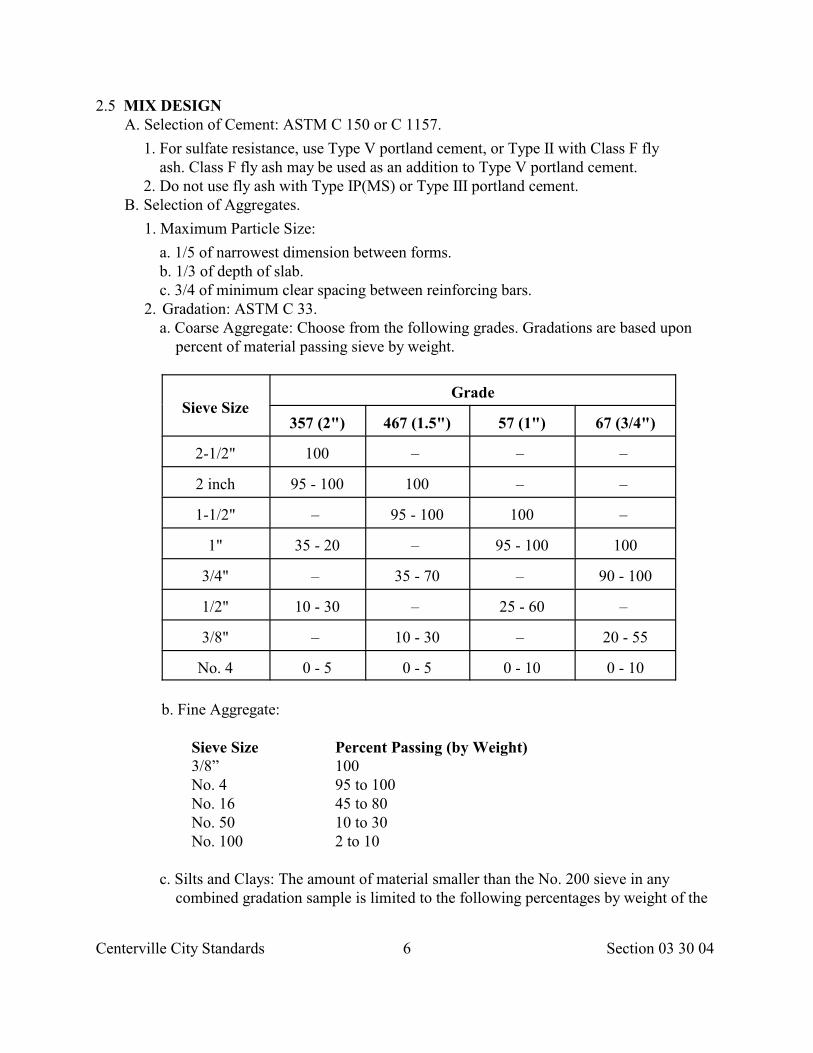
Centerville City Standards 6 Section 03 30 04
2.5 MIX DESIGN A. Selection of Cement: ASTM C 150 or C 1157.
1. For sulfate resistance, use Type V portland cement, or Type II with Class F fly ash. Class F fly ash may be used as an addition to Type V portland cement.
2. Do not use fly ash with Type IP(MS) or Type III portland cement. B. Selection of Aggregates.
1. Maximum Particle Size:
a. 1/5 of narrowest dimension between forms. b. 1/3 of depth of slab. c. 3/4 of minimum clear spacing between reinforcing bars. 2. Gradation: ASTM C 33. a. Coarse Aggregate: Choose from the following grades. Gradations are based upon
percent of material passing sieve by weight.
Sieve SizeGrade
357 (2") 467 (1.5") 57 (1") 67 (3/4")
2-1/2" 100 – – –
2 inch 95 - 100 100 – –
1-1/2" – 95 - 100 100 –
1" 35 - 20 – 95 - 100 100
3/4" – 35 - 70 – 90 - 100
1/2" 10 - 30 – 25 - 60 –
3/8" – 10 - 30 – 20 - 55
No. 4 0 - 5 0 - 5 0 - 10 0 - 10
b. Fine Aggregate:
Sieve Size Percent Passing (by Weight)3/8” 100No. 4 95 to 100No. 16 45 to 80No. 50 10 to 30No. 100 2 to 10
c. Silts and Clays: The amount of material smaller than the No. 200 sieve in any
combined gradation sample is limited to the following percentages by weight of the
Centerville City Standards 7 Section 03 30 04
combined sample.
1. 1.75 percent maximum for concrete subject to abrasion. 2. 3.0 percent maximum for all other concrete. 194
C. Selection of Pozzolan:
1. General: If a blended aggregate passes an unmodified ASTM C 1293 test, use of a pozzolan is Developer’s choice, otherwise select a pozzolan (or blended cement, or both) and determine the effective dosage to meet one of the following tests.
a. ASTM C 1567. The expansion of a cement-pozzolan-aggregate job-mix mortar bar is less than or equal to 0.10 percent at 16 days. Do not use this test if a lithium admixture is used in the job-mix. b. ASTM C 441. The expansion of a test mixture at 56 days is less than or equal to a control mixture prepared with cement with equivalent alkalis between 0.5 and 0.6 percent.
2. Fly Ash (Class F): Allowed as a cement replacement under the following conditions.
a Before replacement is made, use the minimum cement content in the design formula to establish the water/cement ratio. b. Replace up to 20 percent of the cement by weight on a minimum basis of 1 part fly ash to 1 part cement.
c. Submit to City Engineer a quality history of the fly ash identifying a minimum of 20 of the most current ASTM C 618 analysis.
3. Natural Pozzolan (Class N): Allowed as a cement replacement if the 14 day expansion test (ASTM C 1567) with job aggregates, job cement and natural pozzolan does not exceed the 14 day expansion test of job aggregates, job cement and Class F fly ash. 4. Silica Fume: Allowed as a cement replacement if replacement of hydraulic cement on a 1 part silica fume to 1 part cement does not exceed 10 percent, and water/cement ratio is established before cement is replaced with silica fume.
D. Selection of Fiber Reinforcement: The basis for determining material proportions of fiber- reinforced concrete is the Supplier’s responsibility per ASTM C 1116 subject to mix property requirements of this Section. Unless specified otherwise provide synthetic fibers.
E. Selection of Mix Properties: Select and proportion mix to produce appropriate strength, durability and workability. Use ACI 211.1, 211.2, or 211.3, and meet the following properties and limitations.
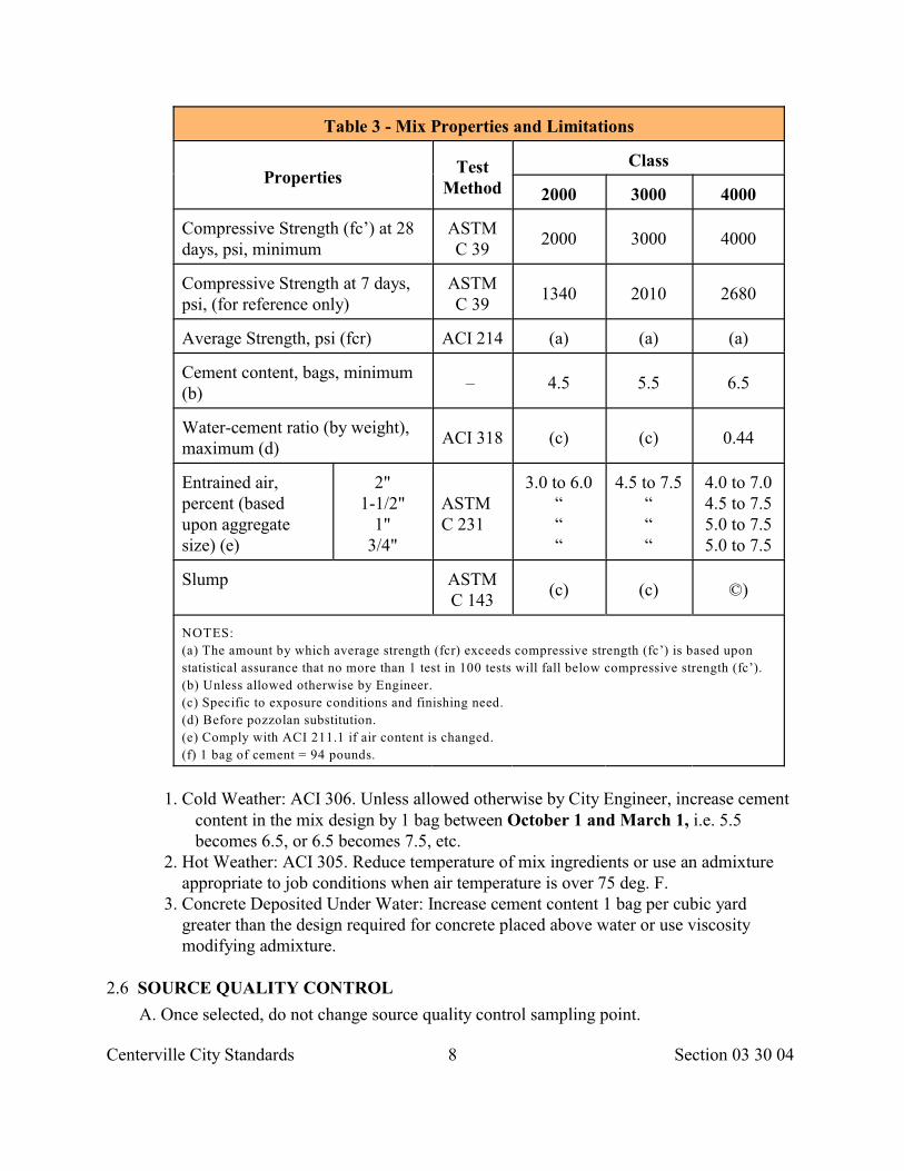
Centerville City Standards 8 Section 03 30 04
Table 3 - Mix Properties and Limitations
PropertiesTest
Method
Class
2000 3000 4000
Compressive Strength (fc’) at 28days, psi, minimum
ASTMC 39
2000 3000 4000
Compressive Strength at 7 days,psi, (for reference only)
ASTMC 39
1340 2010 2680
Average Strength, psi (fcr) ACI 214 (a) (a) (a)
Cement content, bags, minimum(b)
– 4.5 5.5 6.5
Water-cement ratio (by weight),maximum (d)
ACI 318 (c) (c) 0.44
Entrained air,percent (basedupon aggregatesize) (e)
2"1-1/2"
1"3/4"
ASTMC 231
3.0 to 6.0“““
4.5 to 7.5“““
4.0 to 7.04.5 to 7.55.0 to 7.55.0 to 7.5
Slump ASTMC 143
(c) (c) ©)
NOTES:
(a) The amount by which average strength (fcr) exceeds compressive strength (fc’) is based upon
statistical assurance that no more than 1 test in 100 tests will fall below compressive strength (fc’).
(b) Unless allowed otherwise by Engineer.
(c) Specific to exposure conditions and finishing need.
(d) Before pozzolan substitution.
(e) Comply with ACI 211.1 if air content is changed.
(f) 1 bag of cement = 94 pounds.
1. Cold Weather: ACI 306. Unless allowed otherwise by City Engineer, increase cement content in the mix design by 1 bag between October 1 and March 1, i.e. 5.5 becomes 6.5, or 6.5 becomes 7.5, etc. 2. Hot Weather: ACI 305. Reduce temperature of mix ingredients or use an admixture appropriate to job conditions when air temperature is over 75 deg. F. 3. Concrete Deposited Under Water: Increase cement content 1 bag per cubic yard greater than the design required for concrete placed above water or use viscosity modifying admixture.
2.6 SOURCE QUALITY CONTROL
A. Once selected, do not change source quality control sampling point.
Centerville City Standards 9 Section 03 30 04
B. Aggregate:
1. Soundness, ASTM C 88. 2. Alkali-silica Reactivity: ASTM C 289, C 1567, C 227 and C 1293. 3. Petrographically examine fine and coarse aggregate sources once every 3 years per
ASTM C 295. C. Concrete Mix: Obtain samples per ASTM C 172 and run the following tests.
1. Compressive strength, ASTM C 39. 2. Unit weight, ASTM C 138. 3. Slump, ASTM C 143. 4. Air, ASTM C 231. 5. Temperature, ASTM C 1064.
D. Concrete Quality Charts: Comply with ACI 214 and ACI 301. Plot new results andidentify trends on quality control charts that comply in form to ASTM STP 15-C. Showthe Specified Strength (fc'), the required Average Strength (fcr), and the compressivestrength versus date of Sample.
E. Equipment: Certify through the services of a professional engineer that trucks and plantequipment comply with the requirements of the National Ready Mixed ConcreteAssociation. Do so at least every 2 years.
1. Transit Trucks: Equip transit trucks with plates indicating total volume, agitating volume and mix volume.
2. Weights and Measures: Comply with regulatory requirements of State of Utah.
PART 3 EXECUTION
3.1 INSTALLATION
A. Placement, Section 03 30 10.
B. Pavement restoration, Section 33 05 25.
C. Driveways, sidewalks, curb, gutter, Section 32 16 13.
D. Roadway pavement, Section 32 13 13.
3.2 FIELD QUALITY CONTROL
A. Truck Mixed Concrete (Dry Batch): ASTM C 94.
1. Truck Mixer: Fill drum no more than 63 percent of the gross drum volume and no less than 2 cubic yards. Use drum manufacturer’s recommended mixing speed (between 12 18 rpm).
2. Truck Agitator: Do not fill drum greater than 80 percent of the gross drum volume. Use drum manufacturer’s recommended agitating speed (between 2 – 6 rpm).
B. Mixing Plant: ASTM C 94.
1. Use option C and requirements in this section for preparing ready-mixed concrete.
Centerville City Standards 10 Section 03 30 04
2. Use scales certified by the State of Utah. Do not use volume measurement except for water and liquid admixtures.
3. Mixing time must exceed 80 seconds after adding air entrainment admixture. C. Hand Mixing:
1. Do not hand mix batches larger than 0.5 cubic yard. 2. Hand mix only on a watertight platform. 3. Ensure all stones are thoroughly covered with mortar and mixture is of uniform
color and consistency prior to adding water.
END OF SECTION
Centerville City Standards 1 Section 03 30 05
SECTION 03 30 05
CONCRETE TESTING
PART 1 GENERAL
1.1 SECTION INCLUDES A. Concrete sampling and testing requirements.
1.2 REFERENCES A. ACI 318: Building Code Requirements for Reinforced Concrete.
B. ASTM C 31: Standard Practice for Making and Curing Concrete Test Specimens in theField.
C. ASTM C 39: Standard Test Method for Compressive Strength of Cylindrical ConcreteSpecimens.
D. ASTM C 42: Standard Method of Obtaining and Testing Drilled Cores and Sawed Beamsof Concrete.
E. ASTM C 78: Standard Test Method for Flexural Strength of Concrete (Using SimpleBeam with Third-Point Loading).
F. ASTM C 136: Standard Method for Sieve Analysis of Fine and Coarse Aggregates.
G. ASTM C 138: Standard Test Method for Unit Weight, Yield, and Air Content(Gravimetric) of Concrete.
H. ASTM C 143: Standard Test Method for Slump of Portland Cement Concrete.
I. ASTM C 172: Standard Method of Sampling Freshly Mixed Concrete.
J. ASTM C 173: Standard Test Method for Air Content of Freshly Mixed Concrete byVolumetric Method.
K. ASTM C 231: Standard Test Method for Air Content of Freshly Mixed Concrete by thePressure Method.
L. ASTM C 567: Standard Test Method for Unit Weight of Structural LightweightConcrete.
M. ASTM C 1064: Standard Test Method for Temperature of Freshly Mixed PortlandCement Concrete.
N. ASTM D 1077: Standard Practice for Laboratories Testing Concrete and ConcreteAggregates for Use in Construction and Criteria for Laboratory Evaluation.
1.3 SUBMITTALS
A. Concrete Supplier: If requested, submit reports and material certificates verifying concretequality control.
Centerville City Standards 2 Section 03 30 05
B. Laboratory: Promptly submit test data results for 7 and 28 day breaks to Supplier, Developerand City Engineer.
1.4 QUALITY ASSURANCE A. Provide an ASTM D 1077 compliant and ACI certified laboratory. B. Provide level I ACI certified field sampling technicians.
1.5 SITE CONDITIONS
A. Assist City Engineer: Furnish labor to assist City Engineer in obtaining and handlingacceptance samples at site or sources.
B. Store and Cure Test Specimens: Safely store and cure concrete test specimens andacceptance test specimens for first 24 hours.
1. Follow ASTM C 31 in making and curing cylinders or beams at site. Do not move the cylinders or beams for the initial 16 hour cure period. Provideinitial cure temperature as follows.
a. 60 to 80 deg. F. for Class 4,000 or less. b. 68 to 78 deg. F. for Class 5,000 or greater. 2. Equip storage device with an automatic 24 hour temperature recorder with an
accuracy of plus or minus 2 deg. F. 3. Use water containing hydrated lime if water is to be in contact with cylinders or
beams. 4. Ensure the device(s) can accommodate the required number of test cylinders or
beams. Lack of capacity will cause the placement of concrete to cease. 5. Have the storage devices available at the point of placement at least 24 hours
before placement. 6. A 24 hour test run may be required.
1.6 ACCEPTANCE
A. At the Site:
1. Sampling: ASTM C 172. Reject non-complying batches until 2 consecutive batches are compliant then proceed in random batch testing for acceptance.
2. Temperature, ASTM C 1064. 3. Air content, ASTM C 231 or ASTM C 173 if lightweight aggregate is used. 4. Slump, ASTM C 143. 200
B. At the Laboratory: 1. Compressive strength, ASTM C 31. 2. Flexure strength, ASTM C 78.
PART 2 PRODUCTS Not Used
PART 3 EXECUTION
Centerville City Standards 3 Section 03 30 05
3.1 PRECAST PRODUCTS A. Obtain composite Samples from different portions of the batch. B. Make and cure concrete test specimens for acceptance, ASTM C 31. C. Cure all precast products with water vapor or water.
D. Do not damage precast products by stripping forms or handling before the concretereaches its specified strength.
3.2 CAST-IN-PLACE PRODUCTS A. Obtaining Samples:
1. Batch samples, ASTM C 172. 2. Core samples, ASTM C 42.
B. Identify location of tests on test reports. C. Compressive strength , ASTM C 39.
1. Mold 4 test specimens, ASTM C 31. 2. For each strength test perform slump, air, unit weight, and temperature test. 3. Break 1 cylinder at 7 days and 3 cylinders at 28 days. The average strength of 3
cylinder breaks shall be considered the test result. 4. If any one cylinder in a 28 day test shows definite evidence of improper sampling,
molding, handling, curing, or testing, discard the cylinder. The average strength of the remaining cylinders shall be considered the test result.
D. Tensile (flexural) strength, ASTM C 78. 1. Mold 4 test specimens, ASTM C 31. 2. For strength test perform slump, air, unit weight, and temperature test. 3. Break 1 beam at 7 days and 3 beams at 28 days. The average strength of the 3 beam
breaks shall be considered the test result. 4. If any one beam in a 28 day test shows definite evidence of improper sampling,
molding, handling, curing, or testing, discard the beam. The average strength of the remaining beams shall be considered the test result.
E. Aggregate, ASTM C 136 for fine and coarse aggregate. F. Slump test, ASTM C 143. G. Air Test:
1. Normal weight concrete, ASTM C 231. 2. Light weight concrete, ASTM C 173.
H. Unit Weight: 1. Normal weight concrete, ASTM C 138. 2. Light weight concrete, ASTM C 567.
I. When requested, test in-place concrete by impact hammer, sonoscope, or other non-destructive device:
1. To determine relative strengths in various locations in Work. 2. To aid in evaluating concrete strength. 3. To select areas to be cored. 4. To verify quality control in the absence of control testing.
Centerville City Standards 4 Section 03 30 05
3.3 RETESTING DEFECTIVE CONCRETE
A. If Developer desires to do a retest, a request to City Engineer for retesting must be madewithin 35 days from time of concrete placement. No coring or retesting shall be done after 40 days have elapsed from the time of placement.
1. Choose 3 random test locations and verify choice with City Engineer. Obtain retest samples per ASTM C 42 and test compressive strength per ASTM C 39 or flexure strength per ASTM C 78.
2. Establish a chain of custody for all test samples. 3. If concrete placed in the Work will be dry under service condition, air dry cores for 7
days before tests. Unless otherwise specified, use air temperature 60 to 80 deg. F. and relative humidity less than 60 percent.
4. If concrete placed in the Work will be more than superficially wet under service conditions, test cores after moisture conditioning (liquid or vapor water cure).
5. If more than 1 core shows evidence of having been damaged before testing provide replacement cores, otherwise evaluation will be done on 2 or more core samples.
6. Evaluate cores in accordance with ACI 318 requirements. 7. If core tests are inconclusive, or impractical to obtain, or if structural analysis does not
confirm the safety of the Work, load test may be used and evaluated in accordance with ACI 318 requirements.
B. Coat sides of core hole with concrete epoxy resin adhesive. Fill core holes with non-shrink concrete mortar. Match color and texture of surrounding concrete.
C. Within 40 days from time of placement publish the chain of custody record and the results of retesting.
END OF SECTION
Centerville City Standards 1 Section 0 3 30 10
SECTION 03 30 10
CONCRETE PLACEMENT
PART 1 GENERAL
1.1 SECTION INCLUDES
A. Concrete placement for slabs on grade, slabs on fill, structural building frame, and otherconcrete components.
1.2 REFERENCES
A. ACI 301: Specifications for Structural Concrete for Buildings.
B. ACI 305: Hot Weather Concreting.
C. ACI 306: Cold Weather Concreting.
D. ACI 309: Standard Practice for Consolidation of Concrete.
E. ASTM C 881: Standard Specification for Epoxy-Resin-Base Bonding Systems forConcrete.
F. ASTM C 1059: Standard Specification for Latex Agents for Bonding Fresh toHardened Concrete.
1.3 SUBMITTALS
A. Batch Delivery Ticket: For each batch delivered to site, identify.
1. Date and Project description. 2. Producer and plant. 3. Name of contractor. 4. Serial number of ticket. 5. Mix identification. 6. Truck number and time dispatched. 7. Volume of concrete. 8. Type and amount of cement. 9. Total water and water/cement ratio. 10.Water added for receiver of concrete and receiver's initials. 11.Admixture types. 12.Separate weights of fine and coarse aggregate. 13.Statement of whether batch is pre-mixed at plant or mixed in transit.
B. Record of Placed Concrete: Identify record date, location of pour, quantity, airtemperature, and quality control test samples taken.
C. Bonding Compound: Identify product name, type, and chemical analysis.
Centerville City Standards 2 Section 0 3 30 10
1.4 QUALITY ASSURANCE A. Provide ACI certified finishers.
B. Remove and replace any placed concrete suffering hot or cold weather damage.
C. For control testing follow Section 03 30 05 requirements.
1.5 ACCEPTANCE A General:
B. Concrete work that fails to meet any of the following requirements will be considered defective.
1. Placement: a. Reinforcing steel size, quantity, strength, position, damage, or arrangement is not as
specified or does not comply with code. b. Formwork differs from required dimensions or location in such a manner as to
reduce concrete’s strength or load carrying capacity or physical esthetics. c. Workmanship likely to result in deficient strength. 2. Finishing: a. Concrete exposed to view has defects that adversely affect appearance. b. Slab tolerances of Section 03 35 00 are not met. 3. Protection: a. Method of curing is not as specified. b. Inadequate protection of concrete during early stages of hardening and strength
development from 1) temperature extremes.
2) rapid moisture loss.
c. Mechanical injury, construction fires, accidents, or premature removal of formwork likely to result in deficient strength development.
PART 2 PRODUCTS
2.1 MATERIALS
A. Concrete, Section 03 30 04. Class as indicated.
1. For roadway cuts, Section 33 05 25. B. Bonding compound, ASTM C 1059. Either polyvinyl acetate base or acrylic base latex.
1. Use type I in areas not subject to high humidity or immersion in water with minimum bond strength of 400 psi.
2. Use type II in areas subject to high humidity or immersion in water with minimum bond strength of 1250 psi.
C. Vapor retarder, 10 mil thick clear polyethylene sheet. Typerecommended for below grade application.
D. Forms, Section 03 11 00.
Centerville City Standards 3 Section 0 3 30 10
E. Reinforcement, Section 03 20 00.
F. Coverings and curing compound, Section 03 39 00.
G. Shinkage compensating grout, Section 03 61 00.
H. Epoxy adhesive, Section 03 61 00.
PART 3 EXECUTION
3.1 PREPARATION
A. Notify City Engineer minimum 24 hours prior to commencement of concrete placementoperations.
B. Do not allow construction loads to exceed structural capacity.
C. Clean previously placed concrete. Apply bonding compound per manufacturer'sinstructions.
D. At locations where new concrete is dowelled to existing work, drill, remove dust, insertand pack steel dowels with shrink compensating grout.
3.2 EXAMINATION
A. Verify items to be cast into concrete are accurately placed and held securely.
B. Verify slump, air content range, mix identifty, and batch time on delivery ticketmatches mix design.
C. Verify slab steel mats are supported by steel chairs, precast concrete blocks, or other slabbolsters. Do not pour if absent.
3.3 DELIVERY
A. Slump and Air Content: Keep slump and air content within the allowable range. B. Placement Time:
Air Time Temperature After Initial Batching
Less than 90 deg. F. 1–1/2 hoursGreater than 90 deg. F. 1–hour (without retarder)Greater than 90 deg. F. 1–1/2 hours (with retarder)
To increase time past 1-1/2 hours, a hydration stabilizer that isacceptable to Supplier may be used.
C. Tempering:
1. Water may be added if all following conditions are met.
a. The mix design water/cement ratio is not exceeded. b. The delivery ticket allows for addition of water based upon water/cement ratio.
Centerville City Standards 4 Section 0 3 30 10
c. The amount of water added is accurately measured to within 1 gallon of the design addition. d. Water addition is followed by 3 minutes of mixing at mixing speed prior to discharge. e. Supplier and CONTRACTOR mutually agree on who is authorized to add water.
2. Do not add water after 1 cubic yard of concrete has discharged from the deliveryvehicle.
D. Super-plasticizer: Comply with manufacturer's requirements. If none, then as follows.
1. If added at site, add agent using injection equipment capable of rapidly and uniformly distributing the admixture to the concrete. Prior to discharge, mix for a minimum of 5 minutes at a drum rate not less than 12 rpm or more than 15 rpm.
2. If added at plant; do not deliver to site unless batch delivery ticket displays water/cement ratio prior to super-plasticizer addition.
3.4 CONCRETE PLACEMENT
A. Place concrete, ACI 301.
1. Hot Weather Placement: ACI 305. If the rate of evaporation approaches 0.2 lb./ft /hr. 2
precautions against plastic shrinkage cracking are necessary. (i.e. dampening Subgrade and forms; placing concrete at the lowest possible temperature; erecting windbreaks and sunshades; fog sprays; use of evaporation retardants; or rescheduling time of placement).
2. Cold Weather Placement: ACI 306. Non-chloride accelerating admixture may be used in concrete work placed at ambient temperatures below 50 deg. F. Use of admixtures will not relax cold weather placement, curing, or protection requirements.
B. Concrete Temperature: Keep mixed concrete temperature at time of placementbetween 60 deg. F. and 90 deg. F.
C. Do not disturb reinforcement, inserts, embedded parts, and formed joints. D. Do not break or interrupt successive pours such that cold joints occur. E. Honeycomb or embedded debris in concrete is not acceptable.
3.5 JOINTS AND JOINT SEALING
A. Steel edging and jointing tools are acceptable. Preferred aremagnesium, aluminum or wood tools
B. Pavement joint sealing, Section 32 13 73.
3.6 CONSOLIDATION
A. Keep spare vibrator available during concrete placement operations, ACI 309.
3.7 FINISHING
A. Section 03 35 00 and as follows.
Centerville City Standards 5 Section 0 3 30 10
3.8 CURING
A. Section 03 39 00. Use a membrane forming compound unless specified otherwise.
3.9 PROTECTION AND REPAIR
A. Protection: Section 01 66 00. 1. Immediately after placement, protect concrete from premature drying, excessively hot
or cold temperatures, graffiti, and mechanical injury. 2. Maintain concrete with minimal moisture loss at relatively constant temperature for
period necessary for hydration of cement and hardening of concrete. B. Repair:
1. Modify or replace concrete not conforming to required levels, lines, details, and elevations.
2. Structural analysis and additional testing may be required at no additional cost to OWNER when the strength of a structure is considered potentially deficient.
3. To patch imperfections refer to Section 03 35 00 requirements. 4. Remove graffiti and mechanical injury.
END OF SECTION
Centerville City Standards 1 Section 03 35 00
SECTION 03 35 00
CONCRETE FINISHING
PART 1 GENERAL
1.1 SECTION INCLUDES A. Finishing interior and exterior concrete surfaces.
1.2 REFERENCES A. ACI 303: Guide to Cast-in-Place Architectural Concrete Practice.
1.3 SUBMITTALS
A. Name, type, chemical analysis and manufacturer's recommended rate of application forliquid chemical hardener.
1.4 PROJECT CONDITIONS
A. Protect adjacent materials and finishes from dust, dirt and other surface or physicaldamage during finishing operations. Provide protection as required and remove fromsite at completion of Work.
PART 2 PRODUCTS
2.1 MATERIALS
A. Dry Shake: Blend of metallic or mineral aggregate with Portland cement concrete in proportions recommended by manufacture.
B. Proprietary Materials: If permitted or required, proprietary compounds may be used inlieu of or in addition to foregoing materials. Use such compounds per manufacturer'srecommendations.
C. Liquid-Chemical Hardener: Colorless, aqueous solution containing a blend ofmagnesium fluosilicate, zinc fluosilicate and a wetting agent. Mixture contains not lessthan 2 pounds fluosilicate per gallon and does not interfere with adhesives and bonding.
PART 3 EXECUTION
3.1 PREPARATION
A. Examine the areas and conditions under which work of this section will be performed.
Centerville City Standards 2 Section 03 35 00
B. Correct conditions detrimental to timely and proper finishing.
C. Do not proceed until unsatisfactory conditions are corrected.
3.2 FINISHING HORIZONTAL SLABS
A. Do not apply water (i.e. sprinkle) to any surface of concrete when finishing slabs.
B. Edges and Joints: Tools may be made out of steel. Preferred is wood, aluminum ormagnesium.
C. Tolerances:
1. Class A: 1 in 1000. 2. Class B: 1 in 500. 3. Class C: 1 in 250.
D. Float Finish: After concrete has been placed, consolidated, struck-off, and leveled, do notwork further until ready for floating.
1. Begin floating when water sheen has disappeared and surface has sufficient stiffness.
2. During or after first floating, check planeness of entire surface with a 10 feet long straightedge applied at 2 or more different angles.
3. Cut down high spots and fill low spots to the required tolerance. 4. Refloat slab immediately to a uniform sandy texture.
E. Trowel Finish: 1. Do not use steel trowel or a power trowel on exterior concrete or on concrete that
contains more than 3 percent air. 2. First troweling shall produce smooth surface relatively free of defects but which
may still show some trowel marks. 3. Second troweling after surface has stiffened shall make finished surface
essentially free of trowel marks, uniform in texture and appearance. 4. On surfaces intended to support floor coverings, grind off defects that would show
through floor covering. F. Broom or Belt Finish: Sweep surface with brushes, rakes, tines or burlap belt before final set.
G. "Dry Shake" Finish: Give the surface a floated finish. Evenly apply approximately 2/3of a blended unsegregated material.
1. Begin floating immediately after application of first "dry shake". 2. After material has been embedded by floating, apply remainder of blended material to
surface at right angles to previous application. 3. Make second application heavier in any areas not sufficiently covered by first
application. 4. Immediately follow with second floating. 5. After selected material has been embedded by second floating, complete operation with
a broomed, floated, or troweled finish, as indicated. H. Non-slip Finish: Give surface a "dry shake" application, using crushed ceramically bonded
aluminum oxide particles. Apply at 25 pounds per 100 square feet.
Centerville City Standards 3 Section 03 35 00
I. Exposed Aggregate Finish: Immediately after surface of concrete has been leveled totolerance and surface water has dissipated, spread aggregate uniformly over surface toprovide complete coverage to the depth of a single stone.
1. Embed aggregate into surface by light tamping. 2. Float surface until embedded aggregate is fully coated with mortar and surface has
been brought to tolerance. 3. Start exposure of aggregate after matrix has hardened sufficiently to prevent
dislodgment. 4. Flow ample quantities of water, without force, over surface of concrete while matrix
encasing aggregate is removed by brushing with a fine bristle brush. 5. Continue until aggregate is uniformly exposed. 6. An approved chemical retarder sprayed onto freshly floated surface may be used to
extend working time. J. Chemical-Hardener Finish: Apply liquid chemical-hardener finish to interior concrete
floors where indicated. Do not apply liquid chemical hardener on floor areas scheduled toreceive synthetic matrices terrazzo, setting beds for tile, terrazzo, vinyl flooring, or likeitems. Apply hardener after complete curing and drying of concrete surface permanufacturer's recommendations. Evenly apply each coat, and allow 24 hours for dryingbetween coats. After final coat of chemical-hardener solution is applied and dried,remove surplus hardener by scrubbing and mopping with water.
3.3 FINISHING FORMED SURFACES
A. General:
1. Allow concrete to cure not more than 72 hours before commencing surface finish operations, unless approved otherwise.
2. Revise the finishes as needed to secure approval. B. As-Cast Form Finish:
1. Rough: Patch defects, chip or rub off fins exceeding 1/4 inch height. 2. Smooth: Patch tie holes and defects and remove fins completely. a. When surface texture is impaired and form joints misaligned, grind, bush-hammer,
or correct affected concrete. b. Slurry grout areas evidencing minor mortar Leakage to match adjacent concrete. c. Repair major mortar Leakage as a defective area. d. When workmanship is less than acceptable standard, provide one of rubbed finishes.
C. Rubbed Finish:
1. Smooth Rubbed: Remove forms and perform necessary patching as soon afterplacement as possible.
a. Finish newly hardened concrete no later than 24 hours following form removal. b. Wet surfaces and rub with carborundum brick or other abrasive until uniform color
and texture are produced. 2. Grout Cleaned: Undertake no cleaning operations until all
Centerville City Standards 4 Section 03 35 00
contiguous surfaces are completed and accessible.
a. Wet surface of concrete sufficiently to prevent absorption of water from grout. b. Apply grout uniformly. c. Immediately after grouting, scrub surface with cork float or stone to coat surface and
fill voids. d. While grout is still plastic, remove excess grout by working surface with rubber
float or sack. e. After surface whitens from drying, rub vigorously with clean burlap. f. Keep damp for at least 36 hours after final rubbing.
3. Cork Floated: Remove forms within 2 to 3 days of placement where possible. a. Remove ties. b. Remove all burrs and fins. c. Dampen wall surface. d. Apply mortar with firm rubber float or with trowel, filling all surface voids.
e. Compress mortar into voids. f. If mortar surface dries too rapidly to permit proper compaction and finishing, apply a
small amount of water with fog sprayer. g. Produce final texture with cork float using a swirling motion.
D. Unformed Finish:
1. After concrete is placed, strike smooth, tops of walls or buttresses, horizontal offsets, and similar unformed surfaces occurring adjacent to formed surfaces.
2. Float to texture that is reasonably consistent with formed surfaces. 3. Continue final treatment on formed surfaces uniformly across
uniformed surfaces. E. Blasted Finish:
1. Perform abrasive blasting within 24 to 72 hours after casting. 2. Coordinate with form work construction, concrete placement schedule, and formwork
removal to ensure that surfaces are blasted at the same age for uniform results. 3. Reapply curing protection after blast finishing
F. Architectural Finish: Refer to ACI 303.
1. Tooled Finish:
a. Dress thoroughly cured concrete surface with electric, air, or hand tools to uniform texture, and give a bush hammered surface texture.
b. Remove sufficient mortar to exposed coarse aggregate in relief and to fracture coarse aggregate for tooled finish.
G. Patched Finish:
1. Repair defective areas.
a. Remove honeycomb and defective concrete to sound concrete. b. Make edges perpendicular to surface or slightly undercut. c. Featheredges are not permitted.
Centerville City Standards 5 Section 03 35 00
d. Dampen area to be patched and at least 6 inches surrounding it to prevent absorption of patching mortar water.
e. Prepare bonding grout. f. Mix to consistency of thick cream. g. Brush into surface. 2. Tie Holes: Unless indicated otherwise, after being cleaned and thoroughly dampened,
fill tie hole solid with patching mortar. 3. Make any patches in concrete to closely match color and texture of surrounding
surfaces. Determine mix formula for patching mortar by trial and obtain a good color match with concrete when both patch and concrete are cured and dry.
a. Mix white and gray Portland cement as required to match surrounding concrete to produce grout having consistency of thick paint.
b. Use a minimum amount of mixing water. c. Mix patching mortar in advance and allow to stand without frequent manipulation,
without addition of water, until it has reached stiffest placeable consistency. d. After initial set, dress surfaces of patches manually to obtain same texture as
surrounding surfaces. 4. After surface water has evaporated from patch area, brush bond coat into surface.
a. When bond coat begins to lose water sheen, apply patching mortar. b. Thoroughly consolidate mortar into place and strike-off to leave patch slightly
higher than surrounding surface. c. Leave undisturbed for at least 1 hour before final finish. d. Keep patched area damp for 72 hours or apply curing compound. e. Do not use metal tools in finishing an exposed patch. 5. Where as-cast finishes are indicated, total patched area may not exceed 1 in 500 of as-
cast surface. This is in addition to form tie patches, if ties are permitted to fall within as-cast areas.
6. In any finishing process which is intended to expose aggregate on surface, patched areas must show aggregate.
a. Outer 1 inch of patch shall contain same aggregates as surrounding concrete. b. For aggregate transfer finish, patching mixture shall contain same selected colored
aggregates. c. After curing, expose aggregates together with aggregates of adjoining surfaces by
same process.
END OF SECTION
Centerville City Standards 1 Section 03 38 00
SECTION 03 38 00
POST-TENSIONED CONCRETE SLABS
PART 1 GENERAL
1.1 SECTION INCLUDES A. Post-tensioned concrete slabs complete with required tendons, reinforcement and connecting and supporting devices.
1.2 REFERENCES A. ACI 302.1R-04: Guide for Concrete Floor and Slab Construction. This reference standard includes other ASTM material standards. B. ASTM C 143: Test Methods for Slump of Hydraulic Cement Concrete C. ASTM C 31: Standard Practice for Making and Curing Concrete Test Specimens in the Field. D. PTI: Construction and Maintenance Manual for Post-Tensioned Slabs on Ground and foundations. 3 Editionrd
E. PTI: Manual for Certification of Plants Producing Un-bonded Single Strand Tendons, 4 th
Edition. F. PTI: Specifications for Un-bonded Single Strand Tendons, 2 Edition.nd
G. PTI: Design of Post-Tensioned Slabs-on-Ground 3 Edition.rd
H. PTI: Standard Requirements for Design of Shallow Post-Tensioned Concrete Foundation on Expansive Soils. 1 Edition.st
I. PTI: Standard Requirements for Analysis of Shallow Concrete Foundations on Expansive Soils, 1 Edition.st
J. PTI: Training and Certification of Field Personnel for Un-bonded Post-Tensioning Slab-on-Ground Installer/Stressor.
1.3 BUILDER AND ERECTOR QUALIFICATIONS A. Builders and erectors shall be certified and experienced in building post-tensioning slab- on-ground concrete construction. B. Welders: Certified in accordance with AWS D1.1 and AWS D1.4.
1.4 DESIGN CRITERIA A. Design post-tensioning concrete slabs accordance with ACI 318 and PTI design handbook. B. Under direct supervision of Professional Engineer who is fully experienced in design of slabs. C. Design slabs to support required live, dead and construction loads. D. Design tendons and reinforcement to accommodate shrinkage and expansion due to temperature.
Centerville City Standards 2 Section 03 38 00
1.6 DELIVERY, STORAGE AND HANDLING A. Handle and store tendons as per “Construction and Maintenance Manual for Post- Tensioned Slab-on-Ground Foundations”. B. Each jack and gauge shall be calibrated as a set. Care should be taken to ensure that the jack and gauge are never separated.
PART 2 PRODUCTS
2.1 CONCRETE A. Concrete for Above Ground Structures: Class 3000 minimum, in accordance with Section 03 30 04 and ACI 318, unless a different strength of concrete is indicated.
2.2 ACCESSORIES A. Supporting Devices: Steel, in accordance with ASTM A 36. B. Fixed-End Anchor: Applied at the factory according to manufacturers requirements. C. Concrete Reinforcement: Grade 60 reinforcing. D. Tendons: ½ inch diameter 270 ksi with sheathing of polyethylene material.
2.3 LAYOUT BEFORE POURING CONCRETE A. Fabricate required connecting devices, stands, wedges, plates, pocket formers, block outs, and other accessories. B. Ensure reinforcing steel, anchors, inserts, plates, angles and other items are sufficiently embedded, anchored and property located.
2.4 DESIGN DEVIATIONS A. Deviation: Provide installation equivalent to basic intent. Deviations from exact required cross section will be permitted only with written approval. B. Proposed Design: Supported by complete design calculations and drawings by Developer’s Engineer. Changes can not be made to strand spacing, slab thickness with out Developer’s Engineer redesign and City Engineer acceptance.
2.5 OPENINGS A. Provide required openings, 6 inches or larger. If approved, smaller sizes may be field constructed by coring or sawing.
2.6 FINISHES A. Standard Finish: Produced in forms such as plastic or metal lined that impart a smooth finish to the concrete. Small surface holes, normal form joint marks, minor chips and spauls are acceptable if approved. Major or unsightly imperfections, honeycomb or structural defects are not acceptable.
2.7 REPAIR A. Repair of damaged units is acceptable if structural integrity or appearance is not impaired.
Centerville City Standards 3 Section 03 38 00
2.8 ALLOWABLE TOLERANCES A. Length: Plus of minus 3/4 inch, or plus or minus 1/8 inch per 10 feet of length, whichever is greater, or as indicated. B. End Squareness: 1/2 inch maximum. C. Blockouts: 1 inch of centerline location indicated.
PART 3 EXECUTION
3.1 INSTALLATION A. Do not cut openings until concrete has attained its design compressive strength. B. Install members plumb, level, and in alignment within ACI 302.1R-04 and indicated limits of erection tolerances. C. Clean weld marks or other marks, debris, or dirt from exposed surfaces. D. Tension cables according to PTI requirements.
3.2 PERFORMANCE REQUIREMENTS A. Make repairs or replace unsatisfactory slabs as required. B. Rejection: Slabs may be rejected for any one of the following:
1. Exceeding specified installation tolerances. 2. Damaged during construction operations. 3. Exposed-to-view surfaces which develops surface deficiencies. 4. Other defects as listed in ACI or PTI publications.
END OF SECTION
Centerville City Standards 1 Section 03 39 00
SECTION 03 39 00
CONCRETE CURING
PART 1 GENERAL
1.1 SECTION INCLUDES A. Concrete curing requirements.
1.2 REFERENCES A. ACI 301: Specifications for Structural Concrete for Buildings B. ACI 305: Hot Weather Concreting. C. ACI306: Cold Weather Concreting
D. ASTM C 171: Standard Specification for Sheet Materials for Curing Concrete.
E. ASTM C 1315: Standard Specification for Liquid Membrane-Forming CompoundsHaving Special Properties for Curing and Sealing Concrete.
1.3 SUBMITTALS
A. Curing agent data sheet.
B. Curing plan. Describe estimated cure quantity and procedure.
C. Manufacturer certificates, Section 01 33 00 that shows product meets performancecriteria.
D. Manufacturer's recommended installation procedures which, when accepted by CityEngineer, will become the basis for accepting or rejecting installed product.
1.4 QUALITY ASSURANCE A. Use workers knowledgeable of ACI 301, 305, 306.
1.5 PRODUCT HANDLING
A. Protect materials of this section before, during, and after installation.
B. Protect the work and materials of other trades.
C. In the event of damage, immediately make replacements and repair.
1.6 WEATHER LIMITATIONS
A. Above 75 deg. F., ACI 305
B. Below 55 deg. F., ACI 306.
PART 2 PRODUCTS
Centerville City Standards 2 Section 03 39 00
2.1 COVERS A. Water or Fog-spay: Clean, non-staining and non-detrimental to concrete.
B. Sheet Coverings: White waterproof paper, polyethylene film, or polyethylenecoated burlap sheet complying with ASTM C 171.
C. Mat Coverings: Clean roll goods of cotton or burlap fabric.
D. Insulating Coverings: Non-staining curing blankets.
2.2 MEMBRANE FORMING COMPOUND
A. Material.
1. Styrene-acrylic. 2. Styrene-butadiene. 3. Alpha-methylstyrene.
B. Performance Criteria: ASTM C 1315 compound.
1. Type ID Class A (clear with fugitive dye), or 2. Type II Class A or B (white pigmented).
C. Volatile Organic Compounds (VOC): Comply with local, state and federalrequirements.
PART 3 EXECUTION
3.1 PREPARATION
A. Do not use membrane forming curing compound on surfaces that are to receivehardeners.
B. Commence curing operation within 20 minutes after finishing.
3.2 APPLICATION – COVERS
A. Water: Apply water-fog spray or ponding.
B. Absorptive Mat: Place absorptive mat to provide coverage of concrete surfaces andedges. Lap over adjacent absorptive covers. Thoroughly saturate with water and keepcontinuously wet.
C. Moisture-Retaining Sheet: Place cover in widest practicable width with sides and endslapped and sealed to prevent moisture loss. Repair any holes or tears during curingperiod.
D. Formed Surface Curing: Cure formed concrete surfaces, including underside of beams,supported slabs and other similar surfaces by moist curing with forms in place for fullcuring period. If forms are removed prior to curing completion, applying cure film orpenetrant or use methods indicated above, as applicable.
Centerville City Standards 3 Section 03 39 00
3.3 APPLICATION – MEMBRANE FORMING COMPOUND
A. Apply coating continuously and uniformly. Follow manufacturer’s recommendations
B. Protect continuity of film coatings and repair damage during cure period.
C. If forms are removed before expiration of cure period, apply coating to unprotected areas.
3.4 CONCRETE CURE TEMPERATURE
A. During cure period, eliminate thermal shock of concrete by keeping cure temperature eventhroughout extent and depth of concrete.
3.5 SCHEDULE
A. Concrete Exposed to Potable Water (as in Water Storage reservoirs):
1. Moisture cover curing, or 2. Acrylic cure, or 3. Styreen acrylic silane co-polymer cure.
END OF SECTION
Centerville City Standards 1 Section 03 40 00
SECTION 03 40 00
PRECAST CONCRETE
PART 1 GENERAL
1.1 SECTION INCLUDES
A. Pre-cast concrete, complete with required connecting and supporting devices.
1.2 REFERENCES
A. ACI 318: Building Code Requirements for Reinforced Concrete. This reference standardincludes other ASTM material standards.
B. ASTM A 36: Standard Specification for Structural Steel.
C. ASTM C 478: Standard Specification for Precast Reinforced Concrete Manhole Sections.
D. ASTM C 857: Standard Practice for Minimum Structural Design Loading forUnderground Precast Concrete Utility Structures.
E. ASTM C 858: Standard Specification for Underground Precast Concrete Utility Structures.
F. ASTM C 891: Standard Practice for Installation of Underground Precast Concrete UtilityStructures.
G. AWS D1.1: Structural Welding Code Steel.
H. AWS D1.4: Structural Welding Code Reinforcing Steel.
I. PCI: Design Handbook.
J. PCI MNL-116: Quality Control and Assurance for Plant Production of PrestressedConcrete.
K. PCI MNL-117: Quality Control and Assurance for Plant Production of ArchitecturalPrecast Concrete.
1.3 DESIGN CRITERIA
A. Design structural precast concrete units, ACI 318 and PCI design handbook.
B. Design utility precast units, ASTM C 857 and C 858.
C. Under direct supervision of professional engineer who is fullyexperienced in design of units.
D. Design units to support required stripping and handling loads, live, dead and constructionloads.
E. Design component connections to provide adjustment to accommodate misalignment ofstructure during installation.
Centerville City Standards 2 Section 03 40 00
1.4 SHOP DRAWINGS A. Prepare shop drawings under seal of licensed professional. B. Indicate unit locations, unit identification marks, fabrication details, reinforcement,
connection details, pertinent dimensions, and erection support points. Unit identificationmarks to appear on all manufactured units.
C. Do not proceed with fabrication until shop drawings have been accepted by City Engineer.
1.5 QUALITY ASSURANCE
A. Manufacture:
1. Prestressed: PCI certified. 2. Precast Concrete Units: PCI or NPCA certified 3. Precast Utility Structures and Pipe: ACPA certified.
B. Transporter: Acceptable to precast or prestressed product manufacturer.
C. Erector:
1. Prestressed: PCI certified. 2. Precast: Has 5 years minimum experience in erecting precast units.
D. Welders: Certified, AWS D1.1 and AWS D1.4.
1.6 DELIVERY, STORAGE AND HANDLING
A. Handle precast units in positions consistent with their shape and design. Lift and supportonly from support points indicated on shop drawings.
B. Embedded Lifting or Handling Devices: Capable of supporting units in positionsanticipated during manufacture, storage, transportation, and erection.
C. Block and laterally brace units while stored at manufacturers. Provide lateral bracingthat is sufficient to prevent bowing and warping that is clean, nonstaining, and will notinhibit uniform curing of exposed surfaces.
D. Provide edges of units with adequate protection to prevent staining, chipping, orspalling of concrete.
E. Unless otherwise approved in writing, do not deliver units to job site until required forinstallation.
PART 2 PRODUCTS
2.1 CONCRETE
A. Concrete for Above Ground Structures: 5000 psi minimum, Section 03 30 04 and ACI318.
B. Concrete for Underground Structures: Class 4000 minimum, Section 03 30 04 and ASTM
Centerville City Standards 3 Section 03 40 00
C 478 or ASTM C 858.
2.2 ACCESSORIES A. Connecting and Supporting Devices: Steel, ASTM A 36. B. Reinforcement: Grade 60 steel, Section 03 20 00.
2.3 FABRICATION
A. Maintain plant records and quality control program during production of structuralprecast concrete. Make records available to City Engineer.
B. Use molds which are rigid and constructed of material that will result in uniformfinished products.
C. If self consolidating concrete is NOT used, vibrate concrete to ensure properconsolidation, elimination of unintentional cold joints, and minimize entrapped air onsurface.
D. Fabricate required connecting devices, plates, angles, items fit to steel framingmembers, bolts and accessories.
E. Ensure reinforcing steel, anchors, inserts, plates, angles, and other cast-in items aresufficiently embedded, anchored and property located.
F. Ensure finished surfaces of precast structural units are uniform.
G. Cure units under identical conditions to develop specified concrete quality, andminimize appearance blemishes such as non-uniformity, staining or surface cracking.
2.4 DESIGN DEVIATIONS
A. Deviation: Provide installation equivalent to basic intent without additional cost toOWNER. Deviations from exact required cross-section will be permitted only withapproval.
B. Manufacturer's Proposed Design: Supported by complete design calculations anddrawings. When requested, submit design calculations for review bearing seal andsignature of professional engineer.
2.5 OPENINGS
A. Provide required openings, 6 inches or larger. If approved, smaller sizes may be fieldconstructed by coring or sawing.
2.6 FINISHES
A. General: The required finish will be described in one of the following paragraphs. If nofinish is indicated or selected by City Engineer, Standard.
B. Standard Finish: Produced in forms such as plastic or metal lined that impart a smooth
Centerville City Standards 4 Section 03 40 00
finish to the concrete. Small surface holes, normal form joint marks, minor chips andspall are acceptable if approved. Major or unsightly imperfections, honeycomb orstructural defects are not acceptable.
C. Commercial Finish: Produced in forms such as plywood or lumber that impart texture toconcrete. Remove fins and large projections. Fill holes over 3/8 inch. Make faces true andwell defined. Correct exposed ragged edges by rubbing or grinding.
D. Architectural Grade A Finish: Produced in forms such as plastic or metal lined thatimpart smooth finish to concrete. Fill holes over 1/4 inch in diameter with sand-cementpaste. Grind smooth form offsets or fins over 1/8 inch. Coat with neat cement paste usingfloat. After paste coat has dried, rub with burlap to remove loose particles.
E. Architectural Grade B Finish: Produced in forms such as plastic or metal lined thatimpart smooth finish to concrete. Fill holes over 1/4 inch in diameter with sand-cementpaste. Grind smooth form offsets or fins over 1/8 inch.
F. Special Finishes: Sandblasting, acid washing, retarders or form liners as approved by CityEngineer. Special finishes require submittal of two 12 x 12 inch samples showing arepresentative color and texture to be used.
G. Painted Finishes: On concrete to be painted, use a form release agent acceptable to thepaint manufacturer.
2.7 REPAIR
A. Repair of damaged units is acceptable if structural integrity orappearance is not impaired.
2.8 ALLOWABLE TOLERANCES
A. Length: Plus or minus 3/4 inch, or plus or minus 1/8 inch per 10 feet of length,whichever is greater, or as indicated.
B. End Squareness: 1/2 inch maximum.
C. Blockouts: 1 inch of centerline location indicated.
PART 3 EXECUTION
3.1 INSTALLATION
A. Do not install precast units until concrete has attained its design compressivestrength.
B. Install members plumb, level, and in alignment within PCI MNL-116 or PCI MNL-117and indicated limits of erection tolerances.
C. Clean weld marks or other marks, debris, or dirt from exposed surfaces of units.
D. Install underground utility precast units per ASTM C 891.
Centerville City Standards 5 Section 03 40 00
3.2 PERFORMANCE REQUIREMENTS
A. Conduct inspections, perform testing, and make repairs or replace unsatisfactoryprecast units as required.
B. Rejection: Units may be rejected for any one of the following. 1. Exceeding specified installation tolerances. 2. Damaged during construction operations. 3. Exposed-to-view surfaces which develops surface deficiencies. 4. Other defects as listed in PCI MNL-116 or PCI MNL-117.
END OF SECTION
Centerville City Standards 1 Section 03 61 00
SECTION 03 61 00
CEMENTITIOUS GROUTING
PART 1 GENERAL
1.1 SECTION INCLUDES
A. Pre-mixed non-metallic shrinkage resistant grout, pre-mixed water stop hydraulic cementgrout, epoxy grout, and portland cement grout.
1. Grout for leveling beds of structural steel plates. 2. Sealing of joints and gaps between piping and structures. 3. Sealing of joints between construction components.
1.2 REFERENCES
A. ASTM C 109: Standard Test Method for Compressive Strength of Hydraulic CementMortars (Using 2 in. or 50 mm Cube Specimens).
B. ASTM C 144: Standard Specification for Aggregate for Masonry Mortar.
C. ASTM C 150: Standard Specification for Portland Cement.
D. ASTM C 190: Standard Test Method for Tensile Strength of Hydraulic Cement Mortars.
E. ASTM C 207: Standard Specification for Hydrated Lime for Masonry Purposes.
F. ASTM C 472: Standard Methods for Physical Testing of Gypsum Plasters and GypsumConcrete.
G. ASTM C 595: Standard Specification for Blended Hydraulic Cements.
H. ASTM C 881: Standard Specification for Epoxy -Resin -Base Bonding Systems forConcrete.
I. ASTM C 1090: Standard Test Method for Measuring Changes in Height of CylindricalSpecimens from Hydraulic-Cement Grout.
J. ASTM C 1107: Standard Specification for Packaged Dry Hydraulic Cement (Non-Shrink).
K. ASTM C 1157: Standard Performance Specification for Blended Hydraulic Cement.
L. ASTM D 570: Standard Test Method for Water Absorption of Plastics.
M. ASTM D 638: Standard Test Method for Tensile Properties of Plastics.
N. ASTM D 695: Standard Test Method for Compressive Properties of Rigid Plastics.
1.3 SUBMITTALS
A. Grout mix components. Indicate proportions used, environmental conditions, andadmixture limitations. Indicate material "Type", "Grade", and "Class" which suits
Centerville City Standards 2 Section 03 61 00
Project requirements.
B. Manufacturer's data for latex bonding agent.
PART 2 PRODUCTS
2.1 MATERIALS -GENERAL
A. Cement:
1. ASTM C 150 natural color Type II (normal) or Type IIA (air entrained). 2. ASTM C 595, or C 1157: Blended.
B. Lime: ASTM C 207, Type S, hydrated.
C. Water: Clean, non-staining and non-detrimental.
D. Grout Aggregate: ASTM C 144, standard masonry type.
2.2 PORTLAND CEMENT GROUT
A. Proportions by Volume: 1 part Portland cement, and sand equal to 2-1/2 to 3 times sumof volumes of cement and lime.
B. Mix thoroughly with water to form a stiff workable plastic putty.
C. Compressive Strength: ASTM C 109, 2800 psi in 28 days.
2.3 GYPSUM PLASTER GROUT
A. Premixed, prepackaged, wood fiber gypsum plaster with an ASTM C 472 minimumaverage dry compressive strength of 2000 psi in 28 days.
B. Mix with water per manufacturer's instructions for intended use to form a stiff plastic mixrequired for workability.
2.4 CEMENT BASED SHRINKAGE RESISTANT GROUT
A. Grade B or grade C premixed, non-metallic, non-gaseous product; ASTM C 1107 at afluid consistency (flow cone) of 20 to 30 seconds. Thirty-minute-old grout shall flowthrough flow cone after slight agitation, in temperatures of 40 deg. F. to 90 deg. F.
B. Bleeding: None.
C. Compressive Strength: 6500 to 9000 psi, ASTM C 109 in 28 days.
D. Non-shrink percentage: 0.5 percent, ASTM C 1090.
2.5 EPOXY ADHESIVE GROUT
A. Two component material suitable for use on dry or damp surfaces, 100 percent solids,high modulus, moisture insensitive, complying with ASTM C 881.
Centerville City Standards 3 Section 03 61 00
1. Tensile Strength: ASTM D 638, 5000 psi, minimum in 14 days. 2. Tensile Elongation: ASTM D 638, 2 percent minimum. 3. Compressive Strength: ASTM D 695, 6500 psi minimum in 24 hours and 70 deg.
F., 12,500 psi in 28 days and 70 deg. F. 4. Water Absorption: ASTM D 570, 1 percent maximum. 5. Bond Strength: a. Direct Shear: 400 psi. b. Direct Tension: 250 psi. c. Beam Break: 800 psi. 6. Pot Life: 5 minutes maximum at 70 deg. F.
2.6 BONDING GROUT
A. Of approximately 1 part cement to 1 part fine sand passing a No. 30 sieve with approvedlatex bonding agent when allowed.
2.7 PNEUMATICALLY PLACED PLASTER ("GUNITE" OR "SHOTCRETE")
A. Materials: Portland cement, lime, water and sand.
B. Compressive Strength: ASTM C 109, 2800 psi in 28 days.
C. Proportioning: 1 part cement to not more than 5 parts sand.
PART 3 EXECUTION
3.1 INSTALLATION
A. Fill joints, voids, and pockets, completely.
B. Comply with manufacturer's instructions and UBC Chapter 47.
C. Finish surfaces exposed to view smooth.
D. Pneumatically Placed Plaster: Screened and reused rebound material in an amount not greaterthan 25 percent of the total sand in any batch.
END OF SECTION
Centerville City Standards 1 Section 07 19 00
SECTION 07 19 00
WATER REPELLANT
PART 1 GENERAL
1.1 SECTION INCLUDES A. Penetrating sealer over concrete and masonry.
1.2 REFERENCES
A. ASTM C 67: Standard Methods of Sampling and Testing Brick, and Structural ClayTile
B. ASTM C 140: Standard Methods of Sampling and Testing Concrete Masonry Units
C. ASTM C 642: Standard Test Method for Specific Gravity, Absorption, and Voids inHardened Concrete.
D. ASTM C 672: Standard Test Method for Sealing Resistance of Concrete SurfacesExposed to Deicing Chemicals.
E. NCHRP 244 Series IV: Concrete Sealers for Protection of Bridge Structures, NationalCooperative Highway Research Program, Report 244, Dec 1981, TransportationResearch Board, Washington D.C.
1.3 SUBMITTALS
A. Manufacturer's recommended installation procedures.
B. Performance criteria data sheet showing compliance.
PART 2 PRODUCTS
2.1 PENETRATING COMPOUND
A. Material: Developer’s choice of the following.
1. Organo-silane, 2. Organo-siloxane, 3. Silocanate, 4. Potassium silicate. 5. Styrene acrylic silane co-polymer
B. Performance Criteria: 1. Water Absorption Reduction, ASTM C 67, ASTM C 140, or ASTM C 642: 75 percent
minimum
Centerville City Standards 2 Section 07 19 00
2. Scaling Resistance, ASTM C 672: Weight loss less than 2 percent when subject to 500 cycles of freeze-thaw.
3. Chloride Ion Reduction: 75% minimum; NCHRP 244 series IV. . 4. Moisture Vapor Permeability: 100% minimum; NCHRP 244 series IV.
5. Maximum Drying Time: 1-1/2 hours.
C. Volatile Organic Compounds (VOC): Comply with local, state and federal requirements.
PART 3 EXECUTION
3.1 PREPARATION
A. Do not use water repellant on surfaces that are to receive hardeners. Refer to Section 0335 00.
B. Cure new concrete for 28 days prior to sealer application.
C. Remove curing compound before applying sealer. Do not expose large aggregate.
D. Make surfaces dry and free of laitance, dirt, dust, paint, grease, oil, rust, and othercontaminants.
3.2 APPLICATION
A. Apply coating continuously and uniformly. Keep surface wet for 30 to 45 minutes.
END OF SECTION
Centerville City Standards Section 07 92 001
SECTION 07 92 00
JOINT SEALANTS
PART 1 GENERAL
1.1 RELATED DOCUMENTS A. Drawings and general provisions of Contract, including General and Supplementary Conditions and Division-1 Specification sections, apply to work of this section.
1.2 DESCRIPTION OF WORK A. The extent of each form and type of joint sealer is indicated on drawings and by provisions of this section. B. The applications for joint sealers as work of this section include the following:
1. Concrete construction joints. 2. Floor joints (interior). 3. Wall joints (exterior). 4. Refer to Division-8 sections for glazing requirements, not work of this section. 5. Refer to sections of Division 15 and 16 for joint sealers in mechanical and electrical
work; not work of this section. C. General Performance: Except as otherwise indicated, joint sealers are required to establish and maintain airtight and waterproof continuous seals on a permanent bases, within recognized limitations of wear and aging as indicated for each application. Failures of installed sealers to comply with this requirement will be recognized as failures of materials and workmanship.
1.3 SUBMITTALS A. Product Data: Submit manufacturer's product specifications, handling/installation/curing instructions, and performance tested data sheets for elastomeric product required.
1.4 JOB CONDITIONS: A. Weather Conditions: Do not proceed with installation of liquid sealants under unfavorable weather conditions. Install elastomeric sealants when temperature is in lower third of temperature range recommended by manufacturer for installation.
PART 2 PRODUCTS
2.1 ACCEPTABLE MANUFACTURERS A. General: Manufacturers listed in this article include those known to produce the indicated category of prime joint sealer material, either as a nominally pure generic product or as an equivalent-performance modification thereof or proprietary product.
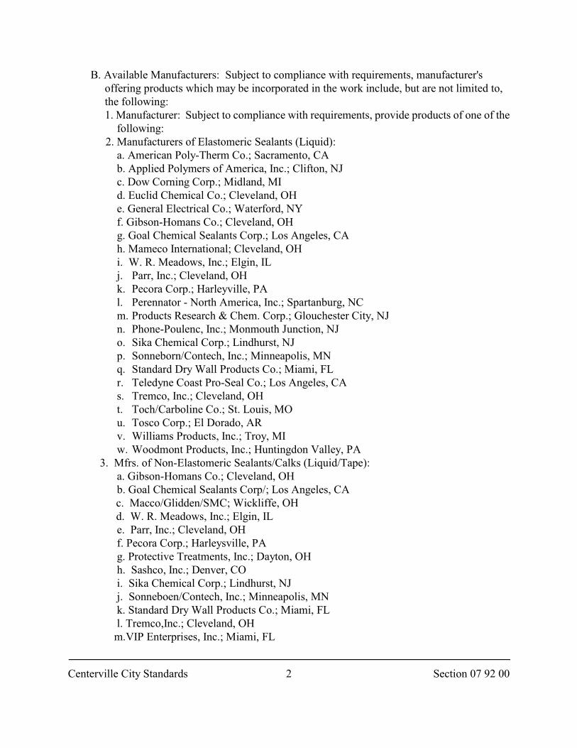
Centerville City Standards Section 07 92 002
B. Available Manufacturers: Subject to compliance with requirements, manufacturer's offering products which may be incorporated in the work include, but are not limited to, the following:
1. Manufacturer: Subject to compliance with requirements, provide products of one of the following: 2. Manufacturers of Elastomeric Sealants (Liquid): a. American Poly-Therm Co.; Sacramento, CA b. Applied Polymers of America, Inc.; Clifton, NJ c. Dow Corning Corp.; Midland, MI d. Euclid Chemical Co.; Cleveland, OH e. General Electrical Co.; Waterford, NY f. Gibson-Homans Co.; Cleveland, OH g. Goal Chemical Sealants Corp.; Los Angeles, CA h. Mameco International; Cleveland, OH i. W. R. Meadows, Inc.; Elgin, IL j. Parr, Inc.; Cleveland, OH k. Pecora Corp.; Harleyville, PA l. Perennator - North America, Inc.; Spartanburg, NC m. Products Research & Chem. Corp.; Glouchester City, NJ n. Phone-Poulenc, Inc.; Monmouth Junction, NJ o. Sika Chemical Corp.; Lindhurst, NJ p. Sonneborn/Contech, Inc.; Minneapolis, MN q. Standard Dry Wall Products Co.; Miami, FL r. Teledyne Coast Pro-Seal Co.; Los Angeles, CA s. Tremco, Inc.; Cleveland, OH t. Toch/Carboline Co.; St. Louis, MO u. Tosco Corp.; El Dorado, AR v. Williams Products, Inc.; Troy, MI w. Woodmont Products, Inc.; Huntingdon Valley, PA3. Mfrs. of Non-Elastomeric Sealants/Calks (Liquid/Tape): a. Gibson-Homans Co.; Cleveland, OH b. Goal Chemical Sealants Corp/; Los Angeles, CA
c. Macco/Glidden/SMC; Wickliffe, OH d. W. R. Meadows, Inc.; Elgin, IL
e. Parr, Inc.; Cleveland, OH f. Pecora Corp.; Harleysville, PA g. Protective Treatments, Inc.; Dayton, OH h. Sashco, Inc.; Denver, CO i. Sika Chemical Corp.; Lindhurst, NJ j. Sonneboen/Contech, Inc.; Minneapolis, MN k. Standard Dry Wall Products Co.; Miami, FL l. Tremco,Inc.; Cleveland, OH m.VIP Enterprises, Inc.; Miami, FL
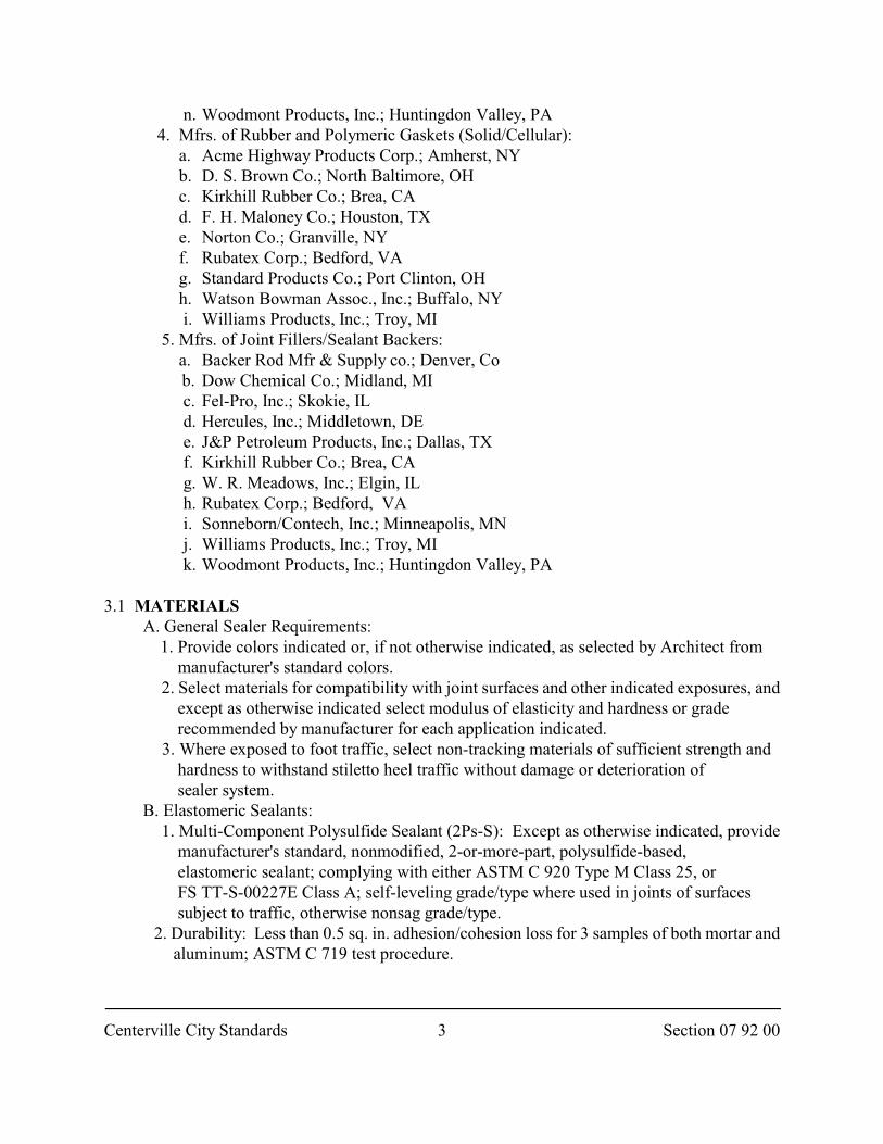
Centerville City Standards Section 07 92 003
n. Woodmont Products, Inc.; Huntingdon Valley, PA 4. Mfrs. of Rubber and Polymeric Gaskets (Solid/Cellular): a. Acme Highway Products Corp.; Amherst, NY b. D. S. Brown Co.; North Baltimore, OH c. Kirkhill Rubber Co.; Brea, CA d. F. H. Maloney Co.; Houston, TX e. Norton Co.; Granville, NY f. Rubatex Corp.; Bedford, VA g. Standard Products Co.; Port Clinton, OH h. Watson Bowman Assoc., Inc.; Buffalo, NY i. Williams Products, Inc.; Troy, MI 5. Mfrs. of Joint Fillers/Sealant Backers: a. Backer Rod Mfr & Supply co.; Denver, Co
b. Dow Chemical Co.; Midland, MI c. Fel-Pro, Inc.; Skokie, IL d. Hercules, Inc.; Middletown, DE e. J&P Petroleum Products, Inc.; Dallas, TX f. Kirkhill Rubber Co.; Brea, CA g. W. R. Meadows, Inc.; Elgin, IL h. Rubatex Corp.; Bedford, VA i. Sonneborn/Contech, Inc.; Minneapolis, MN j. Williams Products, Inc.; Troy, MI k. Woodmont Products, Inc.; Huntingdon Valley, PA
3.1 MATERIALS A. General Sealer Requirements: 1. Provide colors indicated or, if not otherwise indicated, as selected by Architect from manufacturer's standard colors. 2. Select materials for compatibility with joint surfaces and other indicated exposures, and except as otherwise indicated select modulus of elasticity and hardness or grade recommended by manufacturer for each application indicated.
3. Where exposed to foot traffic, select non-tracking materials of sufficient strength and hardness to withstand stiletto heel traffic without damage or deterioration of sealer system. B. Elastomeric Sealants:
1. Multi-Component Polysulfide Sealant (2Ps-S): Except as otherwise indicated, provide manufacturer's standard, nonmodified, 2-or-more-part, polysulfide-based, elastomeric sealant; complying with either ASTM C 920 Type M Class 25, or FS TT-S-00227E Class A; self-leveling grade/type where used in joints of surfaces subject to traffic, otherwise nonsag grade/type. 2. Durability: Less than 0.5 sq. in. adhesion/cohesion loss for 3 samples of both mortar and aluminum; ASTM C 719 test procedure.
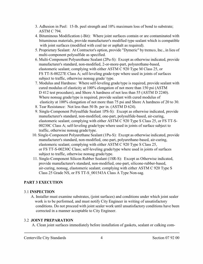
Centerville City Standards Section 07 92 004
3. Adhesion in Peel: 15-lb. peel strength and 10% maximum loss of bond to substrate; ASTM C 794.
4. Bituminous Modification (-Bit): Where joint surfaces contain or are contaminated with bituminous materials, provide manufacturer's modified type sealant which is compatible with joint surfaces (modified with coal tar or asphalt as required).
5. Proprietary Sealant: At Contractor's option, provide "Dymeric" by tremco, Inc., in lieu of multi-component polysulfide as specified.
6. Multi-Component Polyurethane Sealant (2Pu-S): Except as otherwise indicated, provide manufacturer's standard, non-modified, 2-or-more-part, polyurethane-based, elastomeric sealant; complying with either ASTM C 920 Type M Class 25, or FS TT-S-00227E Class A; self-leveling grade-type where used in joints of surfaces subject to traffic, otherwise nonsag grade/ type.
7. Modulus and Hardness: Where self-leveling grade/type is required, provide sealant with cured modulus of elasticity at 100% elongation of not more than 150 psi (ASTM D 412 test procedure), and Shore A hardness of not less than 55 (ASTM D 2240). Where nonsag grade/type is required, provide sealant with cured modulus of elasticity at 100% elongation of not more than 75 psi and Shore A hardness of 20 to 30.
8. Tear Resistance: Not less than 50 lb. per in. (ASTM D 624).9. Single-Component Polysulfide Sealant 1PS-S): Except as otherwise indicated, provide
manufacturer's standard, non-modified, one-part, polysulfide-based, air-curing, elastomeric sealant; complying with either ASTM C 920 Type S Class 25, or FS TT-S- 00230C Class A; self-leveling grade/type where used in joints of surface subject to traffic, otherwise nonsag grade/type. 10. Single-Component Polyurethane Sealant (1Pu-S): Except as otherwise indicated, provide manufacturer's standard, non-modified, one-part, polyurethane-based, air-curing, elastomeric sealant; complying with either ASTM C 920 Type S Class 25, or FS TT-S-00230C Class; self-leveling grade/type where used in joints of surfaces subject to traffic, otherwise nonsag grade/type. 11. Single-Component Silicon Rubber Sealant (1SR-S): Except as Otherwise indicated, provide manufacturer's standard, non-modified, one-part, silicone-rubber-based, air-curing, nonsag, elastomeric sealant; complying with either ASTM C 920 Type S Class 25 Grade NS, or FS TT-S_001543A Class A Type Non-sag.
PART 3 EXECUTION
3.1 INSPECTION A. Installer must examine substrates, (joint surfaces) and conditions under which joint sealer work is to be performed, and must notify City Engineer in writing of unsatisfactory conditions. Do not proceed with joint sealer work until unsatisfactory conditions have been corrected in a manner acceptable to City Engineer.
3.2 JOINT PREPARATION A. Clean joint surfaces immediately before installation of gaskets, sealant or calking com-
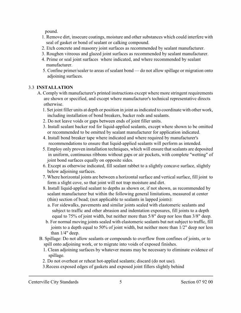
Centerville City Standards Section 07 92 005
pound. 1. Remove dirt, insecure coatings, moisture and other substances which could interfere with
seal of gasket or bond of sealant or calking compound. 2. Etch concrete and masonry joint surfaces as recommended by sealant manufacturer. 3. Roughen vitreous and glazed joint surfaces as recommended by sealant manufacturer.4. Prime or seal joint surfaces where indicated, and where recommended by sealant
manufacturer. 5. Confine primer/sealer to areas of sealant bond — do not allow spillage or migration onto
adjoining surfaces.
3.3 INSTALLATION A. Comply with manufacturer's printed instructions except where more stringent requirements are shown or specified, and except where manufacturer's technical representative directs otherwise.
1. Set joint filler units at depth or position in joint as indicated to coordinate with other work, including installation of bond breakers, backer rods and sealants.
2. Do not leave voids or gaps between ends of joint filler units. 3. Install sealant backer rod for liquid-applied sealants, except where shown to be omitted
or recommended to be omitted by sealant manufacturer for application indicated. 4. Install bond breaker tape where indicated and where required by manufacturer's
recommendations to ensure that liquid-applied sealants will perform as intended. 5. Employ only proven installation techniques, which will ensure that sealants are deposited
in uniform, continuous ribbons without gaps or air pockets, with complete "wetting" of joint bond surfaces equally on opposite sides.
6. Except as otherwise indicated, fill sealant rabbet to a slightly concave surface, slightly below adjoining surfaces.
7. Where horizontal joints are between a horizontal surface and vertical surface, fill joint to form a slight cove, so that joint will not trap moisture and dirt.
8. Install liquid-applied sealant to depths as shown or, if not shown, as recommended by sealant manufacturer but within the following general limitations, measured at center (thin) section of bead; (not applicable to sealants in lapped joints):
a. For sidewalks, pavements and similar joints sealed with elastomeric sealants and subject to traffic and other abrasion and indentation exposures, fill joints to a depth equal to 75% of joint width, but neither more than 5/8" deep nor less than 3/8" deep.
b. For normal moving joints sealed with elastomeric sealants but not subject to traffic, fill joints to a depth equal to 50% of joint width, but neither more than 1/2" deep nor less than 1/4" deep. B. Spillage: Do not allow sealants or compounds to overflow from confines of joints, or to spill onto adjoining work, or to migrate into voids of exposed finishes. 1. Clean adjoining surfaces by whatever means may be necessary to eliminate evidence of spillage. 2. Do not overheat or reheat hot-applied sealants; discard (do not use). 3.Recess exposed edges of gaskets and exposed joint fillers slightly behind
Centerville City Standards Section 07 92 006
adjoining surfaces, unless otherwise shown, so that compressed units will protrude from joints. 4. Bond ends of gaskets together with adhesively or "weld" by other means as recommended by manufacturer to ensure continuous watertight and airtight performance. Miter-cut and bond ends at corners unless molded corner units are provided. 5. Install fire-resistant foamed-in-place filler in openings where indicated, and at thicknesses indicated. 6. Dam bottom of vertical openings and one side of horizontal openings with temporary containment forms or, where required to achieve fire-resistance ratings, provide permanent mineral composition board forms. 7. On horizontal penetrations, provide partial face containment forms where required for form placement. 8. Allow installed fillers to cure 24 hours; remove temporary forms, trim ragged edges with sharp knife; inspect and fill voids with additional filler to form uniform thickness of filler.
3.4 CURE AND PROTECTION A. Cure sealants and caulking compounds in compliance with manufacturer's instructions and recommendations, to obtain high early bond strength, internal cohesive strength and surface durability. B. Advise Contractor of procedures required for cure and protection of joint sealers during construction period, so that they will be without deterioration or damage (other than normal wear and weathering) at time of substantial completion. C. Cure and protect sealants in a manner which will minimize increases in modulus of elasticity and other accelerated aging effects. D. Replace or restore sealants which are damaged or deteriorated during construction period.
END OF SECTION
Centerville City Standards 1 Section 26 05 00
SECTION 26 05 00
ELECTRICAL GENERAL REQUIREMENTS
PART 1 GENERAL
1.1 SECTION INCLUDES A. General requirements for electrical systems.
B. Requirements for submittals, quality assurance, product handling and coordination.
1.2 REFERENCES
A. NFPA 70: National Electrical Code.
1.3 ELECTRICAL SYSTEM LAYOUTS
A. Drawings are diagrammatic, intended to indicate general scope and locations of workto be installed.
B. Furnish as if called for in detail by the Contract Documents all items of labor andmaterial or equipment incidental to or necessary for the complete installation and properoperation the electrical work.
1.4 SUBMITTALS
A. Electrical installation certificate from electrical inspection authority havingjurisdiction.
B. Wiring Layout: Prior to installation of the electrical work, submit a complete wiringlayout, showing arrangement of all circuits, conduits, and control equipment, size ofconduit, conductors, wiring diagrams and connections of all equipment necessary for fullunderstanding and record of the installation.
1.5 QUALITY ASSURANCE
A. Section 01 43 00
B. Workmanship to be neat with good appearance, NFPA 70.
1.6 SUBSTITUTIONS
A. Resolve any conflict arising from use of substituted equipment.
B. Pay all costs required to make equipment comply with intent of City StandardSpecifations. All approvals shall be obtained in writing from City Engineer.
Centerville City Standards 2 Section 26 05 00
1.7 COORDINATION
A. Plan all work to proceed with a minimum of interference with other trades.
B. Inform affected trades of all openings for electrical work. C. Furnish all special frames and sleeves as indicated in other sections.
1.8 PRODUCT HANDLING A. Section 01 65 00.
B. Deliver all materials to the job bearing manufacturer's name and trade name and UL labelin every case where a standard has been established for that particular material.
C. Store product in original containers, protect from elements, and make readily accessiblefor Inspection until ready for installation.
1.9 PROJECT CONDITIONS
A. Notify City Engineer if a discrepancy occurs between the equipment supplied and theintent or function of the equipment, catalog numbers, discontinued products, Drawings,Specifications, etc.
B. Failure to report any conflict does not relieve Developer from meeting the intent of theCity Standard Specifications.
C. Perform all required digging, cutting, incidental work, and make required repairs.
D. Do not cut into any structural element without written approval.
PART 2 PRODUCTS Not Used
PART 3 EXECUTION Not Used
END OF SECTION
Centerville City Standards 1 Section 26 05 13
SECTION 26 05 13
CONDUCTORS AND CABLES
PART 1 GENERAL
1.1 SECTION INCLUDES
A. Installation of wires or cables required for power distribution, service, feeders, andbranch circuits.
B. Related work includes but is not limited to,
1. Excavation, Section 31 23 16. 2. Trench backfill, Section 33 05 20 . 3. Landscape restoration, Section 32 92 00 or Section 32 93 13. 4. Pavement restoration, Section 33 05 25.
1.2 REFERENCES
A. NFPA 70: National Electrical Code.
B. UL: Underwriters' Laboratories, Inc.
1.3 SUBMITTALS
A. Field Test Data: Submit megohmmeter test data for circuits under 600 volts.
PART 2 PRODUCTS
2.1 MATERIALS
A. Building Conductors: Copper, 600 Volt insulation, THW.
B. Branch Circuit Conductors and All Conductors #3 AWG and Smaller: Copperconductor, with TW, THHN, or THWN insulation #10 AWG and smaller, and THWlarger than #10 AWG, where ambient temperature conditions exceed 140 deg. F.
1. Size all conductors; NFPA 70. 2. Minimum size to be #12 AWG. 3. Stranded conductors for #8 AWG and larger. 4. For outlets to fixtures, and in fixture channels (in dry areas); THHN insulated
conductor. 5. In damp locations, under slabs, on exterior provide THWN.
C. Fire Alarm System Conductors: Cross-linked thermosettingpolyethylene (RW90 X-link) type insulating.
Centerville City Standards 2 Section 26 05 13
D. Provide permanent plastic name-tag indicating load feed. E. Use type XHHW conductors for water pumping and regulator stations.
F. Cable Supports: OZ cable supports for vertical risers, type as required by application.
2.2 COLOR AND CODING OF CONDUCTORS
A. 120/208 volt.
1. A Phase -Black 2. B Phase -Red 3. C Phase -Blue 4. Neutral -White 5. Ground -Green
PART 3 EXECUTION
3.1 INSTALLATION
A. Make conductor length for parallel feeders identical.
B. Lace or clip groups of feeder conductors at distribution center, pull-boxes, andwireway. Neatly arrange wiring within cabinets, junction boxes, fixtures, etc.
C. Provide copper grounding conductors and straps.
D. Install wire and cable in code conforming raceway.
E. Use non-detrimental wire pulling lubricant for pulling No. 4 AWG and larger wire.
F. Install wire in conduit runs after concrete and masonry work is complete and aftermoisture is swabbed from conduits.
G. Color code conductors to designate neutral conductor and phase.
H. Furnish necessary reels, reel jacks, and other pulling aids required to prevent damageto wires and cable.
I. Splicing:
1. Install wires and cables continuous without splices from sources of supply to distribution equipment and from source of supply to motor, lighting, or power outlet.
2. Do not use pull boxes for making splices. 3. Do not install splices in conduits.
J. Install all wiring; NFPA 70.
K. Use of cable with more conductors then specified; Developer's option. When done,tape off and labeled extra conductors as spares.
3.2 CONDUCTOR CONNECTIONS
A. Use approved pressure type solderless connectors and lugs for service entrance, feeder,equipment connections and terminal posts.
Centerville City Standards 3 Section 26 05 13
B. Use connectors of a type compatible to conductors, locations, and load. C. Make neutral connection and taps individually in order to prevent the possibility of an
"open-neutral".
D. Make branch circuit connections with UL approved solderless connectors. Do notdepend solely upon a single insulating material to secure connection as well as toinsulate it.
E. After first either silverplating the bars or applying suitable non-oxidizing agents, bolt bussbar connections with adequate nonferrous bolts, washers, and lockwashers.
F. Insulate joints and taps with patented or molded plastic insulators. Use tapescompatible with conductor jackets, temperature, and other conditions.
3.3 SPECIAL WIRING
A. Special Systems: Furnish and install equipment, materials, labor, services, andaccessories required for completion of any special systems of an electrical nature, but notclassified otherwise herein, that may be indicated. Applicable portions of NFPA 70 alsoapply.
3.4 HAZARDOUS AREAS
A. Comply with NFPA 70 when installing wiring, fixtures, and equipment in locationsclassified as "Hazardous Locations".
3.5 AFTER INSTALLATION TEST FOR CABLE 600 VOLTS AND BELOW
A. Prior to energization, test cable and wire for continuity of circuit and for short circuits.Megger all circuit of 100 amp and greater rating.
B. Correct malfunctions.
C. Submit record of megahmmeter readings to City Engineer.
3.6 IDENTIFICATION OF FEEDERS
A. Affix a marker stamped or embossed on each cable at each entry to and exit for eachmanhole, pullhole, pullbox, cable tray switchgear and switch, identifying circuit; i.e."MCCI", "PANEL L" "NO 1" etc.
B. Identification letters to be 1/8 inch size minimum.
C. Markers to be rigid, noncorrosive, attached to feeder cables with feeder identification.
D. Nylon straps to be used to tie the markers.
END OF SECTION
Centerville City Standards 1 Section 26 05 33
SECTION 26 05 33
RACEWAY
PART 1 GENERAL
1.1 SECTION INCLUDES A. Flexible or rigid conduits, couplings, supports, and nonmetallic ducts. B. Related work includes but is not limited to,
1. Trench backfill, Section 33 05 20 . 2. Landscape restoration, Section 32 92 00 or Section 32 93 13. 3. Pavement restoration, Section 33 05 25.
1.2 REFERENCES A. ANSI C80.1: Rigid Steel Conduit -Zinc-Coated. B. ANSI C80.3: Electrical Metallic Tubing -Zinc-Coated.
C. FS W-F-406: Fittings for Cable, Power, Electrical and Conduit, Metal, Flexible.
D. FS WW-C-566: Conduit, Metal, Flexible.
E. NEMA TC6: PVC and ABS Plastic Utilities Duct for Underground Installation.
F. NEMA TC9: Fittings for ABS and PVC Plastic Utilities Duct for UndergroundInstallation.
G. NFPA 70: National Electric Code.
H. UL: Underwriters' Laboratories, Inc.
PART 2 PRODUCTS
2.1 METAL CONDUIT AND TUBING
A. General: Provide metal conduit, tubing and fittings of types, grades, sizes and weights(wall thicknesses) as indicated; with minimum trade size of 3/4 inch.
B. Rigid Metal Conduit (RMC): ANSI C80.1.
C. Intermediate Metal Conduit (IMC): ANSI C80.1.
D. Rigid and Intermediate Steel Conduit Fittings: Provide fully threaded malleable steelcouplings; raintight and concrete tight where required by application. Provide doublelocknuts and metal bushings at conduit termination, use OZ type B bushings on conduits1-1/4 inch and larger.
E. Electrical Metallic Tubing (EMT): ANSI C80.3.
F. EMT Fittings: Provide insulated throat non-indenter type malleable steel fittings; concrete
Centerville City Standards 2 Section 26 05 33
tight where required by application. Install OZ type B bushings on conduits 1-1/4 inchesand larger.
G. Flexible Metal Conduit (FMC): FS WW-C-566, Zinc-coated steel.
H. Flexible Metal Conduit Fittings: FS W-F-406, Type 1, Class 1, Style A.
I. Liquid Tight Flexible Metal Conduit: Provide liquid-tight, flexible metal conduit;constructed of single strip, flexible continuous, interlocked, and double-wrapped steel;galvanized inside and outside; coated with liquid-tight jacket of flexible polyvinylchloride (PVC).
J. Liquid-Tight Flexible Metal Conduit Fittings: FS W-F-406, Type 1, Class 3, Style G.
K. Expansion Fittings: OZ Type AX, or equivalent to suit application.
2.2 NON-METALLIC CONDUIT AND DUCTS
A. General: Minimum trade size: 3/4 inch.
B. Underground PVC Plastic Utilities Duct: NEMA TC6, Type I for encased burial inconcrete, Type II for direct burial.
C. Duct Fittings: NEMA TC9, match to duct type and material.
2.3 CONDUIT, TUBING, AND DUCT ACCESSORIES
A. Provide conduit, tubing and duct accessories of types and sizes, and materials, complyingwith manufacturer's published product information, which mate and match conduit andtubing. Provide manufactured spacers in all duct bank runs.
2.4 LOCKNUTS, BUSHINGS, CONNECTORS, COUPLINGS, AND SUPPORTS
A. General: Provide malleable bushings, except that plastic bushings may be used in lieuof phenolic-lined malleable bushings where "insulating bushings" are required.
B. Provide "double-locknut" system (2 locknuts) throughout, each being tightened wrenchtight as to effectively bond outlet box or cabinet to conduit.
C. Sealing Bushing: OZ Type FSK, WSK, or CSMI as required by application.Provide OZ type CSB internal sealing bushings.
D. Provide insulated-through type ground bushing of the malleable type.
E. Provide connectors or couplings that are proper for the conduit they are used with.Make watertight when required.
F. Provide cadmium plated or galvanized fittings.
G. Provide fittings with die-cut threads unless approved otherwise.
H. EMT connectors used with #4 and larger cable shall have throat liners of suitable plasticinsulation.
Centerville City Standards 3 Section 26 05 33
2.5 INTERIOR OUTLET BOXES
A. Section 26 05 34.
2.6 SCHEDULE OF LOCATIONS
A. Galvanized steel conduit in concrete. B. Electrical metallic tubing in other locations.
C. For underground conduit use rigid, threaded, galvanized steel conduit, or solvent weldedPVC conduit.
D. Make connections to motors and equipment with PVC jacketed flexible conduit andliquid tight connectors. Provide 1/2 inch minimum size for motor connections.
E. Provide flexible conduit for fixture and control wiring with sufficient length of flexibleconduit to avoid transmission of vibration.
PART 3 EXECUTION
3.1 PREPARATION
A. Coordinate utility locations.
B. Excavate; Section 31 23 16.
3.2 INSTALLATION
A. Install conduit concealed in all areas, excluding mechanical and electrical rooms,connections to motors, and connections to surface cabinets.
B. For exposed runs attach surface-mounted conduit with clamps.
C. Coordinate installation of conduit in masonry work.
D. Unless indicated otherwise, do not install conduit larger than 2-1/2 inches in concreteslabs. Provide a minimum concrete cover around conduits of 2 inches.
E. Install conduit free from dents and bruises. Plug ends to prevent entry of dirt andmoisture.
F. Clean out conduit before installation of conductor.
G. Alter conduit routing to avoid structural obstructions, minimizing crossovers.
H. Fill end of conduit with fiberglass where conduits leave heated area and enters unheatedarea.
I. Provide flashing and pitchpockets, making watertight joints where conduits passthrough roof or waterproofing membranes.
J. Install UL approved expansion fittings complete with grounding jumpers where conduitscross building expansion joints. Provide bends or offsets in conduit adjacent to buildingexpansion joints where conduit is installed above suspended buildings.
Centerville City Standards 4 Section 26 05 33
K. Route all exposed conduits parallel or perpendicular to building lines.
L. Make interconnections between difference types of raceways with manufacturedfittings approved by UL.
M. Size raceways; NFPA 70 tables. Do not reduce from any sized indicated.
N. Do not exceed sizes permitted in slabs or walls. O. Do not exceed number of bends allowed in conduit by NFPA 70.
P. Make joints wrench tight or otherwise with minimum resistance to the flow of faultcurrents.
Q. Use furred spaces and chases to an advantage in concealing conduits.
R. Make field bends only where needed and then carefully to minimize wire pulling tensionsand for best appearance in exposed runs.
S. Test conduit runs with lignum vitale ball (mandrel) of 85 percent of conduitdiameter.
T. Cut conduit with hacksaw or other approved pipe cutting tool and ream ends to cleanout all burrs before connecting.
U. Keep conduits at least 6 inches away from steam or hot water pipes, breaching, andboilers, but in no case permit conductors to reach higher than rated temperatures. Avoidtraps in runs and slope conduit to drain.
V. Fasten raceways securely in place. Firmly fasten conduit within 3 feet of each outlet,junction box, cabinet, or fitting. Support metallic conduit, rigid (heavy wall) and EMT atleast every 10 feet. Support rigid nonmetallic conduit in strict accordance with NFPA 70.Use raceway fasteners designed for the purpose.
3.3 SPECIAL CONDUIT FITTINGS
A. Use special conduit fittings as required or indicated. Use UL approved fittings suitablefor location and usage made.
B. At expansion joints use special fittings if cast in concrete slabs.
C. Building Expansion Joints: Where surface conduits, raceways, panels, or light fixtures,span building expansion joints, make satisfactory arrangements to provide the movementprovided for in building structure plus or minus nominal joint width.
3.4 PULL BOXES, WIREWAYS, AND GUTTERS
A. Furnish as indicated, plus any such items required to assemble conduits and otherraceways. Provide Section 26 05 34 pull boxes as dictated by wire pulling requirements.Unless indicated otherwise face into secondary or unfinished rooms.
B. Construction: Code gage galvanized sheet steel and sized strictly in conformancewith NFPA 70 requirements.
C. Finish: Free of burrs, sharp edges, unreamed holes, and sharp-pointed screw or bolts.
Centerville City Standards 5 Section 26 05 33
Paint both inside and out.
D. Coating: When mounted direct to concrete or masonry walls that are below grade orwhere there will be sweating or other moisture present on wall surface, coat backs ofboxes with a heavy coat of black asphalt paint before mounting.
E. Protection: Adequate provisions for preventing damage to conductors either duringpulling in or from weights and tensions when in place.
F. Weatherproof, rain-tight, or special type when indicated or when required byNFPA 70.
3.5 ANCHORS, FASTENERS, AND MISCELLANEOUS SUPPORTS
A. Use compatible anchors in roof or ceiling slabs of concrete from which a load issuspended and anchors used to fasten heavy equipment without lead in their construction.
B. Make exposed conduit fastenings with one-piece, malleable conduit clamps. Two hole,galvanized sheet metal pipe straps may be used on all concealed installations.
C. Use companion bases or backs with conduit clamps when conduit is exposed toweather or continuous moisture.
D. Use ring type hangers on individual runs of conduit 3 inches and larger if suspended,complete with threaded rods. Use adjustable turnbuckles when specified or otherwise asan option.
E. Support multiple runs of suspended conduits from trapeze style hangers suspended withrigid threaded steel rods and with suitable conduit clamps or straps of the same make ascross channels used.
F. Mount multiple runs of conduit on ceiling or wall surfaces.
G. Do not hang or support electrical equipment and materials from roof decks.
3.6 COLOR CODING, EXPOSED CONDUIT
A. Provide color bands 1 inch wide for conduits up to 2 inches in diameter and one-half theconduit diameter for large conduits applied at panel and pull-box locations within eachroom and 500 feet on centers within an area.
B. Color Banding:
1. 120/208 Volt: gray 2. 347/600 Volt: sand 3. Fire Alarm: red 4. Telephone: blue 5. Intercommunication and Sound: yellow 6. Clocks: green 7. Television: rust 8. Low Voltage Switching: black
Centerville City Standards 6 Section 26 05 33
C. Nonmetallic Pressure Piping Label: When applicable, engraved plastic laminate, labelpermanently affixed to main electrical meter panel reading "THIS STRUCTURE HASA NONMETALLIC PRESSURE PIPING SERVICE".
END OF SECTION
Centerville City Standards 1 Section 26 05 34
SECTION 26 05 34
ELECTRICAL BOXES AND FITTINGS
PART 1 GENERAL
1.1 SECTION INCLUDES A. Types of electrical boxes and electrical fitting work.
1.2 REFERENCES
A. NEMA OS 1: Sheet-Steel Outlet Boxes, Device Boxes, Covers, and Box Supports.
B. NEMA OS 2: Nonmetallic Outlet Boxes, Device Boxes, Covers, and Box Supports.
C. NFPA 70: National Electric Code.
D. UL: Underwriters' Laboratories, Inc.
1.3 QUALITY ASSURANCE
A. Comply with NFPA 70 as applicable for installation of electrical boxes and fittings.
B. Comply with NEMA OS 1 and NEMA OS 2 as applicable for outlet boxes, deviceboxes, covers and box supports.
C. Provide electrical boxes and fittings which have been UL-listed and labeled.
PART 2 PRODUCTS
2.1 INTERIOR OUTLET BOXES
A. One piece, galvanized flat rolled sheet steel, cast iron or cast aluminum outlet wiringboxes, of types shapes and sizes, including box depths, to suit each respective locationand installation. If of aluminum, essentially "copper free". Do not use on conduits ofdissimilar metals, except with written permission.
B. Construct with stamped knockouts in back and sides, and with threaded screw holes withcorrosion-resistant screws for securing box and covers and wiring devices.
C. Minimum depth 1-1/4 inches or 2-1/8 inch depth for boxes with 3 or more conduitentries.
D. Use in combination with factory or field bends when indicated or advised. Completeoutlet bodies with mounting brackets, hangers, Extension Rings, fixture studs, cableclamps, metal straps, gaskets, cover, hubs, reducers, and other accessories.
2.2 WEATHERPROOF OUTLET BOX
Centerville City Standards 2 Section 26 05 34
A. Corrosion-resistant cast-metal of types, shapes and sizes (including depth) required.
B. Threaded conduit ends, cast-metal face plates with spring hinged waterproof caps suitablyconfigured for each application, with face plate gaskets and corrosion-resistant fasteners.
2.3 JUNCTION AND PULL BOXES
A. Building Structure Type: Code-gage sheet steel with screw-on covers; of types, shapesand sizes to suit each respective location and installation; with welded seams andequipped with galvanized steel.
B. Buried Type: Plastic body and cover, or pre-cast concrete with screw-on cast iron covers;of types, shapes and sizes to suit each respective location and installation; equipped withstainless steel nuts, bolts, screws and washers.
PART 3 EXECUTION
3.1 PREPARATION
A. Coordinate installation of electrical boxes and fittings with wire/cable and racewayinstallation work.
B. Provide knockout closures to cap unused knockout holes where blanks have beenremoved.
3.2 INSTALLATION
A. Install where indicated, complying with manufacturer's written instruction, applicablerequirements of NFPA 70 and NEMA's "Standard of Installation", and in compliancewith recognized industry practices to ensure that products fulfill requirements.
B. Install coverplates for all boxes; weatherproof outlets for interior and exterior locationsexposed to weather or moisture.
C. Install boxes and fittings to ensure ready accessibility of electrical wiring. Installrecessed boxes with face of box or ring flush with adjacent surface.
D. Fasten boxes rigidly to substrates or structural surfaces to which attached, or solidlyembed boxes in concrete or masonry. Use bar hangers for stud construction. Use of nailsfor securing boxes is prohibited. Set boxes on opposite sides of common wall withminimum 10 inches of conduit between them.
END OF SECTION
Centerville City Standards 1 Section 26 09 26
SECTION 26 09 26
PANELBOARD
PART 1 GENERAL
1.1 SECTION INCLUDES A. Electrical distribution panelboards. B. Connections between fixtures, equipment and panelboards.
1.2 REFERENCES
A. NEMA 1: Instructions for Safe Installation, Operation and Maintenance of PanelboardsRated 600 Volts or Less.
B. NEMA 250: Enclosures for Electrical Equipment (1000 VoltMaximum).
C. NFPA 70: National Electrical Code.
D. UL: Underwriters' Laboratories Inc.
1.3 SUBMITTALS
A. Product Data: Submit manufacturer’s data including specifications, installationinstructions and general recommendations, for each type of panelboard required.
B. Shop Drawings. Submit showing accurately scaled layouts of enclosures and requiredindividual panelboard devices. Show circuit breakers, fusible switches, fuses, ground-fault circuit interrupters, and accessories.
1.4 QUALITY ASSURANCE
A. Construct panelboards to NEMA 1 and NEMA 250 Standards and provide ULlabels.
B. Comply with NFPA 70 pertaining to installation of wiring andequipment in hazardous locations.
C. Make all grounding tight and secure throughout.
PART 2 PRODUCTS
2.1 PANELBOARD -GENERAL
A. Provide panelboards of the same make and key alike with a master key arrangement.
B. Use dead front panelboards with one-piece cabinets constructed from code gage steel.
Centerville City Standards 2 Section 26 09 26
Cabinets shall have knockouts and minimum gutter space of 4 inches on all sides.
C. Provide branches with automatic circuit breakers, thermal-magnetic type, unless indicatedotherwise. Multi-pole breakers shall automatically open all poles when an overloadoccurs in any pole. Branch circuit breakers used for switching duty shall be UL listed asSWD type. Ground fault circuit interrupter protection as required by NFPA 70 shall beprovided by ground fault circuit interrupting breakers. Circuit breakers shall have positivetrip indication as well as clear "off" and "on" indication.
D. Use factory assembled panelboards with amp rating units indicated. Provide spare unitsand blank spaces as indicated. Main circuit breaker or lugs only as indicated.
E. Affix large, permanent individual numbers to each breaker on panelboard face in auniform position. Number starting at the top, with odd numbers used in sequence downleft hand side and even numbers used in sequence down right hand side.
F. Use fronts manufactured with code gage steel, finished with rust inhibiting primer andbaked enamel finish and manufacturer's standard color. Provide doors with flushtumbler type locks. Provide a circuit directory frame and card with a clear plasticcovering inside the door.
G. Furnish locking clips for "off" position only, with "on" trip free travel and installed inall circuits so indicated.
H. Label panel with black phenolic or acceptable alternate engraved nameplate with 1/4 inchhigh lettering on the interior of each panelboard; including panel name and voltage.Provide red nameplate on emergency system panels.
I. For outside locations use a NEMA 4R cabinet.
2.2 PANELBOARD -480 VOLT
A. Voltage: 277/480 volts, 3 phase, 4 wire, S/N, equipped with automatic circuit breaker.
B. Circuit Breakers: Minimum interrupting capacity of 14,000 amps at 277 volts. Usebreakers that are UL rated for use as switches.
C. Locking Clips: 5 minimum per panel.
2.3 PANELBOARD -208 VOLT
A. Voltage: 120/208 volts, 3 phase, 4 wire, S/N, equipped with automatic circuit breakers.
B. Circuit Breakers: Minimum interrupting capacity of 10,000 amps at 120 volts.
PART 3 EXECUTION
3.1 INSTALLATION
A. Provide mounting brackets, bus bar drillings and filler pieces for unused spaces.
Centerville City Standards 3 Section 26 09 26
B. Prepare and affix typewritten directory to inside cover of panelboard indicating loadscontrolled by each circuit.
C. Install per NFPA 70, NEMA, manufacturer's instructions and authorities havingjurisdiction.
END OF SECTION
Centerville City Standards 1 Section 26 13 13
SECTION 26 13 13
CIRCUIT BREAKER
PART 1 GENERAL
1.1 SECTION INCLUDES A. Installation of motor circuit breaker and circuit disconnects.
1.2 REFERENCES
A. NEMA 250-85: Enclosures for Electrical Equipment (1000 Volts Maximum).
B. NEMA KS 1: Enclosed Switches.
C. NFPA 70: National Electrical Code.
D. UL: Underwriters' Laboratories, Inc.
1.3 SUBMITTAL
A. Product Data: Submit manufacturer's data including specifications, installation andgeneral recommendations, for each type of motor and circuit disconnect switchrequired.
B. Shop Drawings: Submit dimensioned drawings of electrical motor and circuitdisconnect switches which have a rating of 100 amperes and larger.
1.4 QUALITY ASSURANCE
A. Conform to:
1. NFPA 70. 2. Local and state codes and to authority having jurisdiction.
B. Provide switches that are UL listed and labeled. Comply with NEMA StandardsPublication No. KS 1 and NFPA 70.
PART 2 PRODUCTS
2.1 GENERAL
A. Motor and circuit disconnects shall have a UL label.
B. Single Phase Disconnect Switches: 2 pole switch.
Centerville City Standards 2 Section 26 13 13
2.2 GENERAL DUTY SWITCHES
A. Sheet steel enclosed switches, fusible or nonfusible as indicated of types, sizes andelectrical characteristics indicated.
B. Rated 240 volts, 60 hertz.
C. Spring assisted, quick-make, quick-break mechanisms. D. Provide single phase or three phase with solid neutral as required by application.
E. Equip with padlock handle in OFF position.
F. Provide NEMA 1 or NEMA 3R enclosures as required by application.
G. Provide fusible switches with Class R rejection fuse clip kits.
2.3 MAINTENANCE STOCK, FUSES
A. Provide as required of classes, types, and ratings for electrical requirements forservice indicated.
B. Furnish additional fuses amounting to 1 unit for every 10 installed units, but not less than 5units of each, for both power and circuit fuses.
PART 3 EXECUTION
3.1 INSTALLATION
A. Install motor and circuit disconnect within sight of controller position.
B. Coordinate motor and circuit disconnect installation work with electrical race way and cablework.
END OF SECTION
Centerville City Standards 1 Section 26 29 13
SECTION 26 29 13
MOTOR CONTROLLER
PART 1 GENERAL
1.1 SECTION INCLUDES A. Installation of motor starters for electric motor driven equipment. B. Types of motor starters include:
1. AC fraction horsepower manual starters. 2. AC line voltage manual starters. 3. AC non-reversing magnetic starters. 4. AC combination non-reversing magnetic starters.
1.2 REFERENCES
A. NEMA 250-85: Enclosures for Electrical Equipment (1000 Volts Maximum).
B. NFPA 70: National Electric Code.
C. UL 508: Electrical Industrial Control Equipment.
1.3 SUBMITTALS
A. Product Data: Manufacturer's data on motor starters.
B. Shop Drawings: Submit dimensioned drawings of motor starters showingaccurately scaled equipment layouts.
C. Motor Voltage/Current Report: After installation is complete including water and airbalancing, measure voltage (L-L and L-N) and full load current of each phase of eachmotor. Submit report showing field readings of voltage, amperage, and thermal heatersize installed for each motor.
1.4 QUALITY ASSURANCE
A. Comply with NEMA, UL 508, and NFPA 70 Standards as applicable to wiring methods,construction and installation of motor starters.
B. Provide units which have been UL-listed and labeled.
PART 2 PRODUCTS
2.1 MOTOR STARTER -GENERAL
A. Provide motor starters and ancillary components; of types, sizes, ratings and electrical
Centerville City Standards 2 Section 26 29 13
characteristics indicated.
B. Materials, design and construction; manufacturer's option unless indicated. C. Thermal Overload Units: Sized to actual running full load current, not to motor plate
current. Size heaters for mechanical equipment after air and water balancing have beencompleted.
2.2 AC FRACTIONAL HP MANUAL STARTER
A. Single-phase, 1 and 2 pole, 300 volt AC maximum unless indicated.
B. Equip with 1 piece thermal overload relay with field adjustment capability of plus orminus 10 percent of nominal overload heater rating; for protection of AC motors of 1 HPand less. (For manually controlled motors in excess of 1 HP, refer to Line VoltageManual Starter specified herein.)
C. Motor Protection Switches: Quick-make, quick-break trip free toggle mechanism, greenpilot lights, with lock-off toggle operated handle. Mount surface units in NEMA 1enclosures, unless indicated. Provide NEMA 3R enclosure in exterior or damp location.Provide flush mounted units with coverplate to match wiring device coverplates.
2.3 AC LINE VOLTAGE MANUAL STARTER
A. 2 or 3 pole, 600 volt AC maximum unless indicated.
B. Equip with pushbutton operator, low voltage protection feature and green pilot light.
C. Motor Protection Switches: Trip free mechanism such that contacts will open under loadand remain open until thermal element has cooled, and unit is reset. Mount surface unitsin NEMA 1 enclosure unless indicated. In exterior or damp location provide NEMA 3R enclosure. Provide flush mounted unitswith coverplate to match wiring device coverplates.
2.4 AC NON-REVERSING MAGNETIC STARTER
A. 2 or 3 pole, 600 volts maximum, with thermal overload position in all phases andinherent under voltage release.
B. Molded case automatic air circuit breakers.
C. Contactor with 3 overload relays.
D. 120 volt holding coil.
E. Pilot light in cover, green resistor type.
F. Reset button, and Hand-Off-Automatic switch in cover, field convertible to Off/Auto orStart/Stop push button.
G. 2 sets of normally open, auxiliary contacts in addition to standard auxiliary holdingcontact supplied with each contactor.
H. 120 volt control transformer of sufficient capacity to handle operating coil and
Centerville City Standards 3 Section 26 29 13
associated controls.
I. Surface mounted starters in NEMA Type 1 enclosure unless indicated. In exterior ordamp locations provide NEMA 3R enclosure.
2.5 AC COMBINATION NON-REVERSING MAGNETIC STARTER
A. Molded case automatic air circuit breakers with rotary operating handle and lock offfacility.
B. Restrict opening of switch enclosure by the use of a defeater screw unless switch isin the "off" position.
C. Contacts with 3 overload delays. D. 120 volt holding coils. E. Pilot light in cover, green resistor type.
F. Reset button, and Hand-Off-Automatic switch in cover, field convertible to Off-Auto orStart-Stop push button.
G. 2 sets of normally open, auxiliary contacts in addition to standard auxiliary holdingcontact supplied with each contactor.
H. 120 volt control transformer of sufficient capacity to handle operating coil and associatedcontrols.
2.6 MAINTENANCE STOCK, FUSES
A. Provide as required of classes, types, and ratings for electricalrequirements for service indicated.
B. Furnish additional fuses amounting to 1 unit for every 10 installed units, but not less than 5units of each, for both power and circuit fuses.
PART 3 EXECUTION
3.1 INSTALLATION
A. Install NEMA size motor protection switches. For units not using NEMA rating, useequivalent NEMA size.
B. In finished areas mount motor protection switches flush and install suitable cover-plates.
C. Install heaters correlated with full load current of motor provided.
D. Install fuses in fusible circuit breaker, if any. Mount chart inside each starter indicatingheater type, size, and ampere rating.
END OF SECTION
Centerville City Standards 1 Section 26 56 19
SECTION 26 56 19
ROADWAY LIGHTING
PART 1 GENERAL
1.1 SECTION INCLUDES A. Materials and procedures for installing roadway lighting system. B. Testing, painting, restoration and salvage. C. Related work includes but is not limited to,
1. Landscape restoration, Section 32 92 00 or Section 32 93 13. 2. Pavement restoration, Section 33 05 25.
1.2 REFERENCES A. ASTM B 3: Standard Specification for Soft or Annealed Copper Wire.
B. ASTM B 8: Standard Specification for Concentric-Lay-Stranded Copper Conductors,Hard, Medium-Hard, or Soft.
C. ASTM D 2301: Standard Specification for Vinyl Chloride Plastic Pressure-Sensitive Electrical Insulating Tape.
D. IES: Illuminating Engineering Society.
E. NEMA 250: Enclosures for Electrical Equipment (1000 VoltsMaximum).
F. NFPA 70: National Electric Code.
G. SSPC PS 1.4: Three-Coat Oil-Alkyd (Lead-and-Chromate-Free) Painting System forGalvanized or Non-Galvanized Steel (with Zinc Dust-Zinc Oxide Linseed OilPrimer).
H. UL: Underwriters' Laboratories, Inc.
1.3 SUBMITTALS
A. Shop Drawings and Product Data: Complete, bound, indexed, large enough for all items included. When requested, supplement the following list by such other data as may be required, including detailed scale drawings and wiring diagrams of any special equipment and of any proposed deviation from the City Standard Specifications.
1. Performance data for luminaires, including lighting contours on the roadway surface and average maintained level of light in foot-candles.
2. Shop drawings for luminaires showing pertinent physical characteristics, type of light source, and wattage.
3. Shop drawings of ornamental poles. 4. Luminaire supports.
Centerville City Standards 2 Section 26 56 19
5. Pole bases. 6. Wiring schematic. 7. Fixture mounting height.8. Pedestal. 9. Drawing showing location of poles, pedestal and underground power conduit.
B. Warranties and instruction sheets.C. Electrical system design, stamped by a licenced Electrical Engineer. D. Testing results.
1.4 MAINTAINING EXISTING AND TEMPORARY ELECTRICAL SYSTEMS
A. Notify City Engineer prior to performing any work on existing systems.
B. Allow 20 feet minimum overhead clearance across thoroughfares and 12 feet minimumclearance above sidewalk areas. Do not run temporary conductor on top of the ground oracross any sidewalk area unless protected in an electrical raceway and barricaded.
C. Maintain existing electrical systems or approved temporary replacements, in effectiveoperation for the benefit of the traveling public during the progress of the Work, exceptwhen shutdown is permitted to allow for alteration or removal of the systems. Do notinterfere with the regular lighting schedule.
PART 2 PRODUCTS
2.1 EXISTING MATERIALS
A. Where existing systems are to be modified, incorporate existing material in revisedsystem, Salvage or abandon as indicated.
2.2 CONDUCTORS
A. Materials: Solid or stranded copper of size indicated conforming to ASTM B 3 andASTM B 8. Insulation; RHH-RHW-USE grade cross link polyethylene compound.
B. Splicing: Compatible with cable insulation and water seal forunderground use. Comply with UL code.
C. Conduit: As indicated. Section 26 05 33.
D. Color and coding of 120/240 volt, Section 26 05 13.
2.3 POLES AND LUMINAIRE SUPPORTS
A. Provide poles and luminaire supports conforming to the height, type, configuration,and base detail indicated.
Centerville City Standards 3 Section 26 56 19
2.4 JUNCTION BOXES
A. Buried type; Section 26 05 34 and as follows.
1. Precast reinforced concrete in paved surfaces. 2. Plastic in landscaped surfaces.3. Minimum size 14" x 20". 4. UL Listed.
B. Cover Stencil: "Street Lighting". Where box contains street lighting voltage greaterthan 600 volts, stencil "High Voltage".
2.5 INSULATING TAPE A. Type 1 vinyl chloride, ASTM D 2301.
2.6 LUMINAIRE
A. Luminaire: Die cast aluminum housing complete with reflector, refractor, lampsocket, slipfitter, replaceable air filter, ballast components or as indicated.
1. Lamp wattage, voltage, and IES distribution type as indicated. 2. Not less than 10 degrees of adjustment above a horizontal position, and not less
than 5 degrees of adjustment from a vertical position. 3. Lower housing door assembly removable with quick disconnect plugs to permit field maintenance or upgrading to other lamp types.
4. Glare shields when indicated. B. Mercury Constant Wattage Regulated Ballasts: Prewired ballast with minimum primary
power factor of 90 percent with normal secondary load with sufficient open circuitvoltage to start lamps at minus 20 deg. F. Ballast shall provide regulation within 5 percent variation in lamp watts with a 10percent variation in primary voltage.
C. High Pressure Sodium Lamps: 250 or 400 watts as indicated.
D. Bonding and Grounding: Copper wire strap No. 6 AWG minimum.
E. Paint: None.
2.7 CONTROL EQUIPMENT
A. Photo-electric control sensitive between 1 and 5 foot candles, minimum.
B. Failure of any electrical component will energize the lighting circuit.
C. Control Relay Contacts Rating: Switch on at 3,000 watts minimum.
D.Remote Control Relays: Normally open.
E. Relays: Either mechanical armature type or mercury tube type, single or double pole, oras indicated.
1. Mechanical armature type: An operating coil (120 volts), a laminated core, a laminated armature, terminals and silver alloy contacts.
Centerville City Standards 4 Section 26 56 19
2. Mercury tube type: An operating coil, hermetically sealed mercury tubes and terminals. Contacts shall be made either mercury to mercury or between mercury and alloy resistant to arcing and mercury amalgamation.
F. Enclosure: NEMA 250 Type 4 with dead front panel, keyed padlock
G. Paint: Waterproof paint.
2.8 POLYSULFIDE BASE, SINGLE COMPONENT SEALANT
A. Chemical curing; capable of being continuously immersed in water, withstandmovement up to 20 percent of joint width, and satisfactorily applied throughout atemperature range to 40 to 80 deg. F., Shore A hardness of minimum 15 and maximum
50; nonstaining and non-bleeding; color as selected by City Engineer.
2.9 CONCRETE AND GROUT A. Cast-in-place concrete: Class 3000, Section 03 30 04. B. Grout: Cement, Section 03 61 00.
2.10 PEDESTAL
A. Milbank CP3B “ML” Series commercial Pedestal or equivalent.
PART 3 EXECUTION
3.1 PREPARATION A. Coordinate utility locations; Section 01 31 13. B. Excavate; Section 31 23 16 and backfill; Section 33 05 20.
C. Do not disturb roadway surface, sidewalk, curb, gutter, or other obstructionswithout approval.
D. Do not block or restrict pedestrian traffic, vehicle traffic, drainage or utilities.
E. Barricade all Excavations in traveled ways.
F. Compact excavated Trench material; Section 33 05 20 to the requirements of theadjacent areas.
G. After backfilling Excavations, maintain smooth and well-drained surfaces untilpermanent repairs are effected.
H. Legally dispose of all excess or waste material.
3.2 POLE FOUNDATION
A. Construct foundation per details indicated and Section 34 41 13.
Centerville City Standards 5 Section 26 56 19
B. Locations:
1. 18 inches clear from pull box. 2. Not in pedestrian access way. 3. Unless specified otherwise: a. 5 feet from new tree. b. 10 feet from existing tree, driveway, or hydrant. c. Center of park strip or 24 inches clear from top back of curb on wide park strips.
3.3 CONDUIT INSTALLATION
A. Use rigid steel conduit in areas subject to vehicular load, on the surface of structures, inside of structures and foundations, between structures, and the adjacent pull boxeslocated next to structures.
B. Place conduit as follows.
Location Depth of Burial, inches
In front of curb faces 36 to 60 Back of the back of curb 24 to 36Railroad tracks 36 to 60 Primary power cables 40 minimum
C. Use sizes of conduit indicated or use larger sizes for any run at no additional cost toOWNER. No expanding or reducing fittings will be permitted.
D. Make field cuts square and true so that the ends will come together for fullcircumference. Paint threads on all rigid steel conduit with rust preventive paint beforecouplings are made. Repair damaged coating on galvanized steel conduit.
E. Cap all conduit ends with standard pipe caps until wiring is installed. When caps areremoved from metallic conduit, provide threaded ends and approved conduit bushings.
F. Clean all existing underground conduit to be incorporated into new system with amandrel and blow out with compressed air. Where existing rigid steel conduitsystems are to be modified or extended, install rigid steel conduit.
G. Make changes in direction by bending the conduit to a radius which will meet code or,preferable, by the use of standard bends or elbows.
H. Install a No. 12 AWG pull wire or equivalent strength cord in all conduits which are toreceive future conductors. Leave at least 2 feet of pull wire extending beyond each endof the conduit run and secure.
I. Center conduit ends within the bolt circle of traffic signal poles or pedestals.
J. Pack conduit ends with sealant after conductors are installed.
K. Cap all conduit terminated without a pull box and identify its location by monumenting.
3.4 CONDUCTOR INSTALLATION
A. Install wiring per the appropriate articles of NFPA 70. Neatly arrange wiring withincabinets, junction boxes, etc.
B. Splice only at junction boxes, transformer leads, in pole bases, or at control equipment.
Centerville City Standards 6 Section 26 56 19
Splice conductors as per manufacturer's recommendations and codes. Provide a fusedconnector between the line and the ballast, accessible at the hand holes located in thepoles.
C. Provide conduit to separate low-voltage conductors from high-voltage conductors inthe same raceway (i.e. poles).
D. Splice insulation shall consist of layers of vinyl chloride, electrical insulating tapeapplied to a thickness equal to and well lapped over the original insulation to provideuninterrupted underwater operation.
E. Leave 2 feet of slack at each pole. Leave 18 inches of slack above top of pull box grade.
F. Mark termination of each conductor. Where circuit and phase are clearly indicated byconductor insulation, bands need not be used, otherwise use bands.
3.5 GROUNDING INSTALLATION
A. Effectively ground metallic cable sheaths, metal conduit, nonmetallic conduit grounding wire, ballast and transformer cases, service equipment, anchor bolts, metal poles, andpedestals, and make mechanically and electrically secure to form a continuous system.Use a copper wire strap for bonding and grounding jumpers of the same cross-sectionalarea as No. 6 AWG for all lighting systems.
B. Ground one side of the secondary circuit of series-multiple and step-down transformers.Ground metal conduit, service equipment, and neutral conductor at service point asrequired by NEC and electricity company with grounding conductor No. 6 AWG orlarger.
C. In all nonmetallic (PVC) type conduit, provide a No. 8 AWG bare copper wirecontinuously and ground at each junction box.
D. At each multiple service point, unless otherwise indicated, furnish a ground electrode.Use copper coated ground electrodes of steel or iron in one piece lengths at least 3/4 inchin diameter. Do not use electrodes of nonferrous materials less than 1/2 inch in diameter.
E. Bond metal poles by means of a No. 8 AWG bonding wire attached from a groundingbushing to a foundation bolt or to a 3/16 inch or larger brass or bronze bolt installed inthe lower portion of the pole.
F. On wood poles, ground all equipment mounted less than 8 feet above the ground surface.
G. Ground metallic conduit or bonding conductor system at intervals less than 500 feet toone of the following:
1. 1 inch galvanized pipe driven 8 feet deep. 2. 1/2 inch copper rod driven 8 feet deep. 3. Metal water main with the approval of the water company. Clean water main
thoroughly prior to connection. H. Use galvanized grounding bushings and bonding jumpers for bonding of metallic
conduit in a concrete pull box. Use lock nuts for bonding of metallic conduit in steel pullboxes, one inside and one outside of the box.
Centerville City Standards 7 Section 26 56 19
I. Pull Boxes: Install 3/4 inch x 10 feet copper clad ground rods at each pull box, 6inches above bottom. Ground all metal parts, neutral and ground wire with #6 B.C.Use exothermic weld or hammerlock connection.
3.6 JUNCTION AND PULL BOX INSTALLATION
A. Install at the locations indicated, and at additional points when conduit runs are morethan 200 feet. Add such additional boxes as may be desired to facilitate the work.
B. Rest bottom of pull box firmly on a 12 inches thick bed of 1 inch crushed rock extendinga minimum of 6 inches beyond the outside edge of box.
C. Establish grade of top of boxes as for foundations.
D. Place long side of box parallel to curb unless indicated.
E. Use box extensions if ballasts or transformers are installed in box.
F. Do not install boxes in Driveway aprons.
3.7 LUMINAIRES AND BALLASTS INSTALLATION A. Immediately prior to installation, clean all light control surfaces,
refractors, and reflectors to provide the maximum lumen output possible. Clean per theluminaire manufacturer's recommendations.
B. Mount at the height indicated.
C. Adjust luminaires uniformly to give the optimum light distribution.
3.8 PAINTING
A. Apply coatings.
B. Recoat all painted equipment when relocated.
C. Use 2 coats of paint on relocated and new work.
3.9 FIELD QUALITY CONTROL
A. Conduct the following tests in the presence of the City Engineer on all lightingcircuits and record the date and time of test.
1. Test for continuity of each circuit. 2. Test for grounds in each circuit. 3. Megger test at 500 volts DC on each completed lighting circuit. The insulation
resistance to ground shall be not less than 10 megohms. 4. Test voltage and current on each circuit.
B. Functional Test:
1. Perform a functional test in which it is demonstrated that each and every part of the system functions as specified or intended.
Centerville City Standards 8 Section 26 56 19
2. A functional test for each new or modified electrical system will consist of not less than 5 days of continuous, satisfactory operation. If unsatisfactory performance of the system develops, correct the condition and repeat the test until the 5 day continuous satisfactory operation is obtained.
3. Do not start functional tests or turn-ons on Friday, or on the day preceding a legal holiday.
4. Shutdowns caused by factors beyond Developer's control will not constitute discontinuity of the functional test.
C. Replace or correct any material revealed by these tests to be faulty.
D. Provide equipment, personnel, cable connections, and electrical energy for testing.Certify that each circuit has been completely tested and testing procedures aresatisfied.
3.10 SALVAGE
A. Terminate all conduit abandoned in place at least 5 inches below finished grade.
B. Exercise care in removing equipment to be reused or salvaged so that it will remain inthe condition existing prior to its removal.
3.11 RESTORATION
A. Replace damaged equipment, concrete work or other fixtures disturbed or damaged bythe installation.
B. Restore or replace roadway pavement cuts, Section 33 05 25.
C. Restore or replace disturbed planting’s in landscaped areas.
END OF SECTION
Centerville City Standards 1 Section 31 05 10
SECTION 31 05 10
BOUNDARY MARKERS AND SURVEY MONUMENTS
PART 1 GENERAL
1.1 SECTION INCLUDES
A. Materials and procedures for installing boundary markers and survey monuments.
1.2 PERFORMANCE REQUIREMENTS
A. Identify the land surveyor who set the marker plates and reference marks.
B. For vertical control datum use Mean Sea Level datum adjusted by United States Coastand Geodetic Survey for the location of survey.
C. Vertical Accuracy: 3rd order.
D. Make all individual tape measurements to the nearest 0.01 of a foot, with tape correctionsfor temperature, sag, suspension, etc. noted on all field notes requiring suchmeasurements.
E. Horizontal Accuracy:
1. 1:10,000 minimum for urban areas. 2. 1:20,000 minimum for metropolitan areas.
1.3 SUBMITTALS
A. Survey notes and drawings showing:
1. All monuments found, set, reset, or replaced, describing their kind, size, and location and giving other data relating thereto.
2. Lines of survey, concrete structures containing reference marks, types of marks installed, distances and angles from monument referenced.
3. Witness monuments, basis of bearings, bearings, length of lines to monuments or corners witnessed and scale of drawing.
4. Errors of closure and method of adjustment. 5. Memorandum of oaths and certificates. 6. Narrative describing purpose of survey. 7. Any other data necessary for the interpretation of the various items and locations of the
points, lines, and areas shown.
B. Copies of plats filed with the County Recorder.
1.4 QUALITY ASSURANCE
Centerville City Standards 2 Section 31 05 10
A. Use a land surveyor who complies with Utah licensing law and who is acceptable to theCity Engineer to supervise the setting or resetting of monuments and boundary markers.
B. Make surveys in conformance with the accepted practice of land surveying and complywith all pertinent Laws and Regulations of land survey regulatory agencies andauthority having jurisdiction.
PART 2 PRODUCTS
2.1 MONUMENT
A. Monument Post: Minimum 3 feet long, precast or cast-in-place concrete. Make exposed surface of finished monument posts uniform, even texture, and free ofholes, cracks, and chipped edges.
B. Marker Plate: Brass or bronze or as indicated.
2.2 FRAME AND COVER
A. Asphalt coated, heavy duty, cast iron.
2.3 LOT LINE WITNESS MARKER
A. Brass surveyor's tag or brass nail set in a lead filled hole in concrete.
2.4 REBAR CORNER MARKER
A. No. 5 rebar, at least 18 inches long with the top fitted with a nonferrous survey cap and stamped with land surveyor's registration number.
2.5 PIPE CORNER MARKERS
A. 1 inch internal diameter galvanized steel pipe at least 18 inches long, or 2 inches internaldiameter galvanized steel pipe at least 36 inches long.
B. Fit pipe with concrete or mortar plug, tagged with surveyor's license number.
C. Fix tag in concrete or mortar plug with a 1 inch minimum long bent brass brad.
2.6 FIELD NOTE PAPER
A. 20 pound bond paper minimum with format of documents acceptable to City Engineer.
2.7 CONCRETE
A. Cast-in-place: Class 4000 minimum, Section 03 30 04 or
B. Precast: Class 5000 minimum, Section 03 40 00.
Centerville City Standards 3 Section 31 05 10
PART 3 EXECUTION
3.1 PREPARATION
A. Identify utility locations.
B. Excavation, Section 31 23 16.
3.2 HORIZONTAL CONTROL
A. Set base horizontal ground control upon a minimum of 2 United States Coast andGeodetic Survey triangulation stations or equivalent, and tie to the Lambert ConformalConic Projection for Establishment of the State Plane Coordinate System with LocalDatum Adjustment within the Project area.
3.3 BEARING BASE
A. Refer all directional measurements to one "bearing base". Actual measurements may beequated to bearings and linear measurements shown on any record (i.e., plats, officialmaps, descriptions, or approved field notes of lines resurveyed that are shown on suchrecords used in the survey).
3.4 TIE TO EXISTING MONUMENTS
A. Tie into a monument which has State Plane Coordinates if the monument is within 1/2mile of the proposed survey site or at a selected location.
3.5 CORNER MARKERS
A. Site Boundary: Install pipe corner markers.
B. Lot Boundary: Install rebar corner markers for lot corners. Do not use rebar where pipecorner markers are installed as a boundary marker and a corner marker.
3.6 LOT LINE WITNESS MARKER
A. Witness all lot lines by installing 1/2 inch surveyor tags in sidewalk. If sidewalk doesnot exist, install tags in curb or mass concrete.
3.7 MONUMENTS
A. Locate monument post so reference point falls within 1 inch diameter circle in thecenter of marker plate. Install marker plate in survey monument post before theconcrete has acquired its initial set.
B. Compact backfill soil; Section 33 05 05 to a Modified Proctor Density of 95 percent orgreater.
Centerville City Standards 4 Section 31 05 10
C. Set top of frames and covers 1/4 inch lower than Pavement surface. Recess markerplate a minimum of 4 inches below cover.
D. Install monument so frame and cover does not contact monument or marker plate.
3.8 DAMAGED MONUMENTS
A. Replace survey control monuments which are disturbed or destroyed by Developer.
B. If City Engineer allows replacement of project survey control monuments which are lostor destroyed, use a licensed land surveyor to re-establish control monuments based uponoriginal survey control.
END OF SECTION
Centerville City Standards 1 Section 31 05 13
SECTION 31 05 13
COMMON FILL
PART 1 GENERAL
1.1 SECTION INCLUDES A. Common fill materials.
1.2 REFERENCES
A. ASTM C 136: Standard Method for Sieve Analysis of Fine and Coarse Aggregates.
B. ASTM D 1883: Standard Test Method for CBR (California Bearing Ratio) ofLaboratory-Compacted Soils.
C. ASTM D 2487: Standard Test Method for Classification of Soils for EngineeringPurposes.
D. ASTM D 2844: Test Method for Resistance R-Value and Expansion Pressure ofCompacted Soils.
E. ASTM D 3282: Standard Practice for Classification of Soils and Soil-Aggregate Mixturesfor Highway Construction Purposes.
F. ASTM D 3740: Standard Recommended Practice for Evaluation of Agencies Engaged inTesting and/or Inspection of Soil and Rock as Used in Engineering Design andConstruction.
1.3 SUBMITTALS
A. Prior to delivering material to site, identify.
1. Name of Supplier and source, And. 2. Gradation of common fill material.
B. If a change in source of material is required, submit name of Supplier, source and gradation analysis of material prior to delivery to site.
1.4 QUALITY ASSURANCE
A. Use a laboratory that follows and complies with ASTM D 3740.
B. Reject common fill products that do not meet requirements of this section.
C. Remove any product found defective after installation and install acceptable product.
1.5 ACCEPTANCE
A. General:
Centerville City Standards 2 Section 31 05 13
1. Acceptance is by Lot. One Lot is one day’s production. 2. Dispute resolution; Section 01 35 10.
B. Roadway Backfill: Sub-lot size is 5,000 tons.
PART 2 PRODUCTS
2.1 BORROW A. Classifications A-1-a through A-4, ASTM D 3282.
2.2 GRANULAR BORROW A. Classifications A-1-a, A-1-b, A-2-4, or A-3, ASTM D 3282.
B. Material meets design CBR-value (ASTM D 1883) or R value (ASTM D 2844) forsuitability of source, not for project control testing.
2.3 GRANULAR BACKFILL BORROW
A. Classification A-1, ASTM D 3282.
B. Well graded.
C. Particle size; 2 inch maximum.
D. Material meets design CBR-value (ASTM D 1883) or R value (ASTM D 2844) forsuitability of source, not for project control testing.
2.4 RECYCLED FILL
A. Material: Pulverized portland cement concrete, pulverized asphalt pavement orcombination, either mixed with or not mixed with a new aggregate.
B. Gradation: Meet the requirements of this Section based upon use; e.g. borrow, granularborrow, granular backfill borrow, etc.
2.5 NATIVE
A. When allowed by City Engineer, material obtained from Excavations may be used as fill,provided organic material, rubbish, debris, and other objectionable materials are removed.
2.6 CLAY
A. Classification CL, CL-ML, or ML, ASTM D 2487.
B. Free of organic matter, frozen material, debris, rocks, and deleterious materials.
C. Homogeneous, relatively uniform.
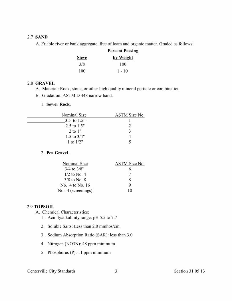
Centerville City Standards 3 Section 31 05 13
2.7 SAND
A. Friable river or bank aggregate, free of loam and organic matter. Graded as follows:
Percent Passing
Sieve by Weight
3/8 100
100 1 - 10
2.8 GRAVEL A. Material: Rock, stone, or other high quality mineral particle or combination.
B. Gradation: ASTM D 448 narrow band.
1. Sewer Rock.
Nominal Size ASTM Size No.3.5 to 1.5” 12.5 to 1.5" 2
2 to 1" 31.5 to 3/4" 41 to 1/2" 5
2. Pea Gravel.
Nominal Size ASTM Size No.3/4 to 3/8” 61/2 to No. 4 73/8 to No. 8 8
No. 4 to No. 16 9No. 4 (screenings) 10
2.9 TOPSOIL A. Chemical Characteristics:
1. Acidity/alkalinity range: pH 5.5 to 7.7
2. Soluble Salts: Less than 2.0 mmhos/cm.
3. Sodium Absorption Ratio (SAR): less than 3.0
4. Nitrogen (NO3N): 48 ppm minimum
5. Phosphorus (P): 11 ppm minimum
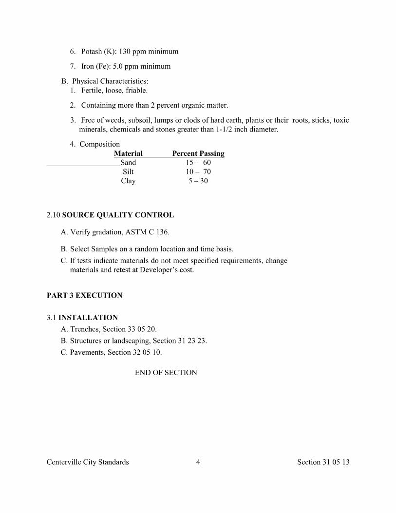
Centerville City Standards 4 Section 31 05 13
6. Potash (K): 130 ppm minimum
7. Iron (Fe): 5.0 ppm minimum
B. Physical Characteristics: 1. Fertile, loose, friable.
2. Containing more than 2 percent organic matter.
3. Free of weeds, subsoil, lumps or clods of hard earth, plants or their roots, sticks, toxicminerals, chemicals and stones greater than 1-1/2 inch diameter.
4. CompositionMaterial Percent Passing
Sand 15 – 60Silt 10 – 70Clay 5 – 30
2.10 SOURCE QUALITY CONTROL
A. Verify gradation, ASTM C 136.
B. Select Samples on a random location and time basis.
C. If tests indicate materials do not meet specified requirements, changematerials and retest at Developer’s cost.
PART 3 EXECUTION
3.1 INSTALLATION
A. Trenches, Section 33 05 20.
B. Structures or landscaping, Section 31 23 23.
C. Pavements, Section 32 05 10.
END OF SECTION
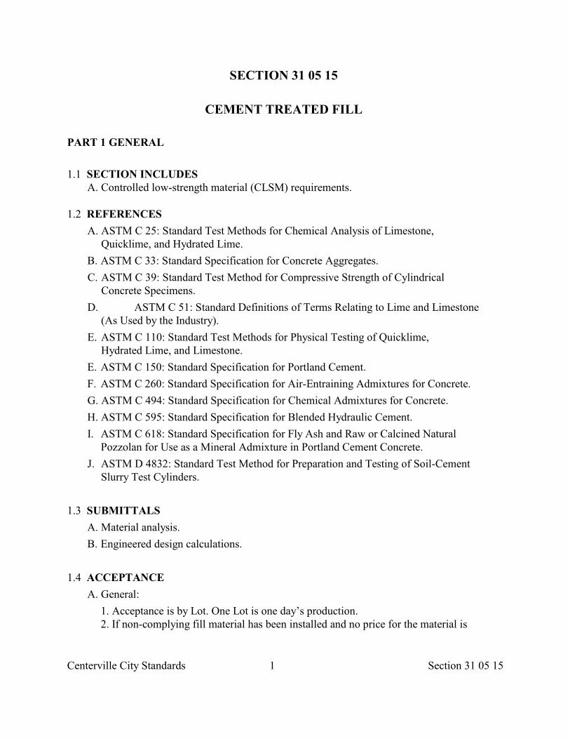
Centerville City Standards 1 Section 31 05 15
SECTION 31 05 15
CEMENT TREATED FILL
PART 1 GENERAL
1.1 SECTION INCLUDES A. Controlled low-strength material (CLSM) requirements.
1.2 REFERENCES
A. ASTM C 25: Standard Test Methods for Chemical Analysis of Limestone,Quicklime, and Hydrated Lime.
B. ASTM C 33: Standard Specification for Concrete Aggregates.
C. ASTM C 39: Standard Test Method for Compressive Strength of CylindricalConcrete Specimens.
D. ASTM C 51: Standard Definitions of Terms Relating to Lime and Limestone(As Used by the Industry).
E. ASTM C 110: Standard Test Methods for Physical Testing of Quicklime,Hydrated Lime, and Limestone.
E. ASTM C 150: Standard Specification for Portland Cement.
F. ASTM C 260: Standard Specification for Air-Entraining Admixtures for Concrete.
G. ASTM C 494: Standard Specification for Chemical Admixtures for Concrete.
H. ASTM C 595: Standard Specification for Blended Hydraulic Cement.
I. ASTM C 618: Standard Specification for Fly Ash and Raw or Calcined NaturalPozzolan for Use as a Mineral Admixture in Portland Cement Concrete.
J. ASTM D 4832: Standard Test Method for Preparation and Testing of Soil-CementSlurry Test Cylinders.
1.3 SUBMITTALS
A. Material analysis.
B. Engineered design calculations.
1.4 ACCEPTANCE
A. General:
1. Acceptance is by Lot. One Lot is one day’s production. 2. If non-complying fill material has been installed and no price for the material is
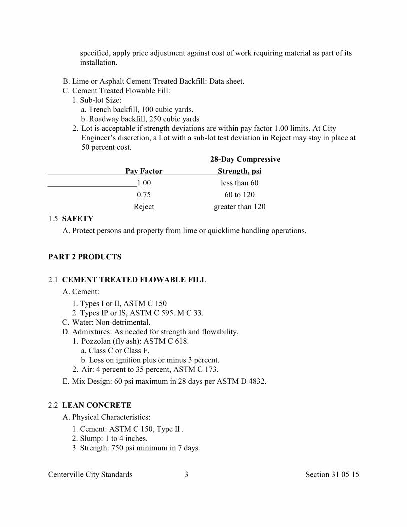
Centerville City Standards 3 Section 31 05 15
specified, apply price adjustment against cost of work requiring material as part of its installation.
B. Lime or Asphalt Cement Treated Backfill: Data sheet. C. Cement Treated Flowable Fill:
1. Sub-lot Size: a. Trench backfill, 100 cubic yards. b. Roadway backfill, 250 cubic yards
2. Lot is acceptable if strength deviations are within pay factor 1.00 limits. At CityEngineer’s discretion, a Lot with a sub-lot test deviation in Reject may stay in place at50 percent cost.
28-Day Compressive
Pay Factor Strength, psi
1.00 less than 60
0.75 60 to 120
Reject greater than 120
1.5 SAFETY
A. Protect persons and property from lime or quicklime handling operations.
PART 2 PRODUCTS
2.1 CEMENT TREATED FLOWABLE FILL
A. Cement:
1. Types I or II, ASTM C 150 2. Types IP or IS, ASTM C 595. M C 33.
C. Water: Non-detrimental. D. Admixtures: As needed for strength and flowability.
1. Pozzolan (fly ash): ASTM C 618. a. Class C or Class F. b. Loss on ignition plus or minus 3 percent.
2. Air: 4 percent to 35 percent, ASTM C 173.
E. Mix Design: 60 psi maximum in 28 days per ASTM D 4832.
2.2 LEAN CONCRETE
A. Physical Characteristics:
1. Cement: ASTM C 150, Type II . 2. Slump: 1 to 4 inches. 3. Strength: 750 psi minimum in 7 days.
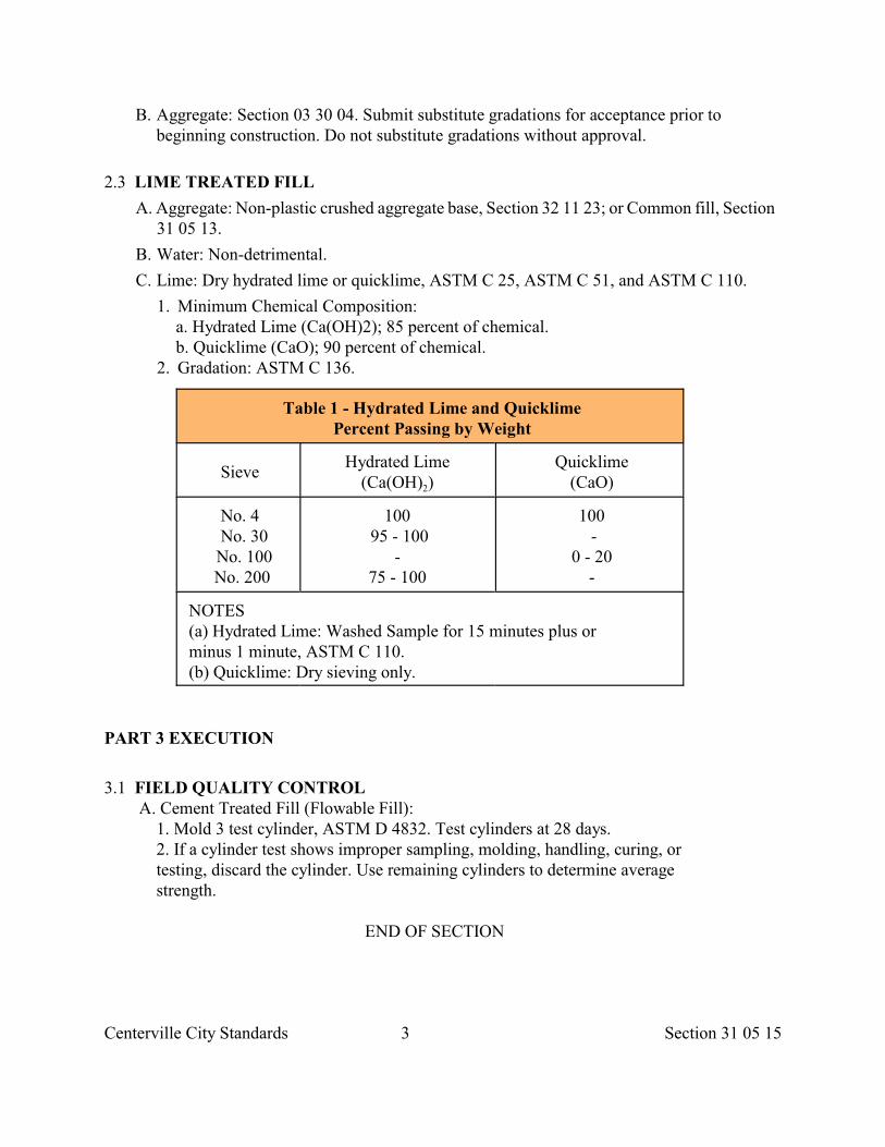
Centerville City Standards 3 Section 31 05 15
B. Aggregate: Section 03 30 04. Submit substitute gradations for acceptance prior tobeginning construction. Do not substitute gradations without approval.
2.3 LIME TREATED FILL
A. Aggregate: Non-plastic crushed aggregate base, Section 32 11 23; or Common fill, Section31 05 13.
B. Water: Non-detrimental.
C. Lime: Dry hydrated lime or quicklime, ASTM C 25, ASTM C 51, and ASTM C 110.
1. Minimum Chemical Composition: a. Hydrated Lime (Ca(OH)2); 85 percent of chemical. b. Quicklime (CaO); 90 percent of chemical.
2. Gradation: ASTM C 136.
Table 1 - Hydrated Lime and QuicklimePercent Passing by Weight
SieveHydrated Lime
2(Ca(OH) )Quicklime
(CaO)
No. 4 No. 30 No. 100 No. 200
100 95 - 100
- 75 - 100
100 -
0 - 20-
NOTES (a) Hydrated Lime: Washed Sample for 15 minutes plus or minus 1 minute, ASTM C 110.(b) Quicklime: Dry sieving only.
PART 3 EXECUTION
3.1 FIELD QUALITY CONTROL A. Cement Treated Fill (Flowable Fill):
1. Mold 3 test cylinder, ASTM D 4832. Test cylinders at 28 days. 2. If a cylinder test shows improper sampling, molding, handling, curing, or testing, discard the cylinder. Use remaining cylinders to determine average strength.
END OF SECTION
Centerville City Standards 1 Section 31 05 19
SECTION 31 05 19
GEOTEXTILES
PART 1 GENERAL
1.1 SECTION INCLUDES A. Geotextile fabrics.
1.2 REFERENCES
A. ASTM D 146: Standard Methods of Sampling and Testing Bitumen-Saturated Felts andWoven Fabrics for Roofing and Waterproofing.
B. ASTM D 276: Standard Test Methods for Identification of Fibers in Textiles.
C. ASTM D 882: Standard Test Methods for Tensile Properties of Thin Plastic Sheeting.
D. ASTM D 3786: Standard Test Method for Hydraulic Bursting Strength of Knitted Goodsand Nonwoven Fabrics -Diaphragm Bursting Strength Tester Method.
E. ASTM D 4354: Standard Practice for Sampling of Geotextiles for Testing.
F. ASTM D 4355: Standard Test Method for Deterioration of Geotextiles from Exposure toUltraviolet Light and Water (Xenon -Arc Type Apparatus).
G. ASTM D 4491: Standard Test Methods for Water Permeability of Geotextiles byPermittivity.
H. ASTM D 4533: Standard Test Method for Trapezoid Tearing Strength of Geotextiles.
I. ASTM D 4632: Standard Test Method for Breaking Load and Elongation ofGeotextiles (Grab Method).
J. ASTM D 4751: Standard Test Method for Determining Apparent Opening Size for aGeotextile.
K. ASTM D 4759: Standard Practice for Determining Specification Conformance ofGeosynthetics.
L. ASTM D 4833: Standard Test Method for Index Puncture Resistance of Geotextiles,Geomembranes, and Related Products.
M. ASTM D 4873: Standard Guide for Identification, Storage, and Handling ofGeotextiles.
N. ASTM E 96: Standard Test Methods for Water Vapor Transmission of Materials. O. ASTM E 154: Standard Methods of Testing Materials for Use as Vapor Barriers Under
Concrete Slabs and as Ground Cover in Crawl Spaces.
1.3 DEFINITIONS
A. MARV (acronym for minimum average roll value): A statistical value of a particular test
Centerville City Standards 2 Section 31 05 19
property embracing 95 percent confidence level of all possible values of that property.For a normally distributed set of data, it is approximately the mean value plus and minustwo standard deviations.
1.4 SUBMITTALS
A. Submit prior to use:
1. Sample of geotextile. 2. Manufacture's certificate that each fabric complies with requirements of this section.
1.5 DELIVERY STORAGE AND HANDLING
A. Label fabric, ASTM D 4873.
B. Deliver geotextile dry, in a wrapping that protects it from the elements during shippingand storage. Keep fabric dry.
C. Protect geotextile from ultraviolet light and temperature greater than 140 deg. F. untilapplication.
1.6 QUALITY ASSURANCE
A. Provide manufacturer’s on-site technical supervision and assistance.
PART 2 PRODUCTS
2.1 GEOTEXTILE -GENERAL
A. Stated values are for non-critical, non-severe applications.
B. Fabric consists of synthetic fibers at least 85 percent by weight of polyolefins,polyesters or polyamides.
C. Resistant to chemical attack, rot and mildew.
D. No tears or defects that adversely alter fabric's physical properties.
E. All numerical values represent minimum average roll values in the weaker principaldirection.
2.2 STABILIZATION-SEPARATION GEOTEXTILES
A. Woven or non-woven fabric. Meet the following properties and survivability ratings.
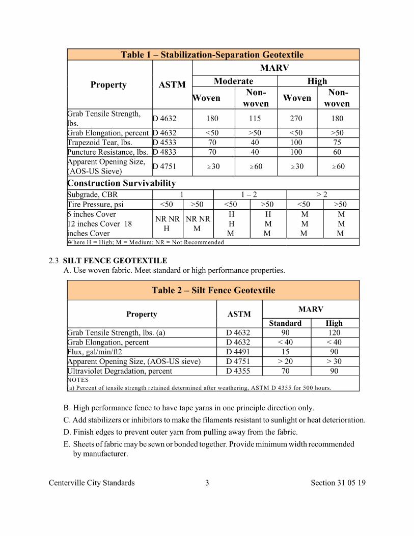
Centerville City Standards 3 Section 31 05 19
Table 1 – Stabilization-Separation Geotextile
Property ASTM
MARV
Moderate High
Woven Non-
wovenWoven
Non-woven
Grab Tensile Strength,lbs.
D 4632 180 115 270 180
Grab Elongation, percent D 4632 <50 >50 <50 >50 Trapezoid Tear, lbs. D 4533 70 40 100 75 Puncture Resistance, lbs. D 4833 70 40 100 60 Apparent Opening Size,(AOS-US Sieve)
D 4751 $30 $60 $30 $60
Construction Survivability Subgrade, CBR 1 1 – 2 > 2 Tire Pressure, psi <50 >50 <50 >50 <50 >50 6 inches Cover12 inches Cover 18inches Cover
NR NRH
NR NRM
HHM
HMM
MMM
MMM
Where H = High; M = Medium; NR = Not Recommended
2.3 SILT FENCE GEOTEXTILE A. Use woven fabric. Meet standard or high performance properties.
Table 2 – Silt Fence Geotextile
Property ASTMMARV
Standard High Grab Tensile Strength, lbs. (a) D 4632 90 120 Grab Elongation, percent D 4632 < 40 < 40 Flux, gal/min/ft2 D 4491 15 90 Apparent Opening Size, (AOS-US sieve) D 4751 > 20 > 30 Ultraviolet Degradation, percent D 4355 70 90 NOTES
(a) Percent of tensile strength retained determined after weathering, ASTM D 4355 for 500 hours.
B. High performance fence to have tape yarns in one principle direction only.
C. Add stabilizers or inhibitors to make the filaments resistant to sunlight or heat deterioration.
D. Finish edges to prevent outer yarn from pulling away from the fabric.
E. Sheets of fabric may be sewn or bonded together. Provide minimum width recommendedby manufacturer.
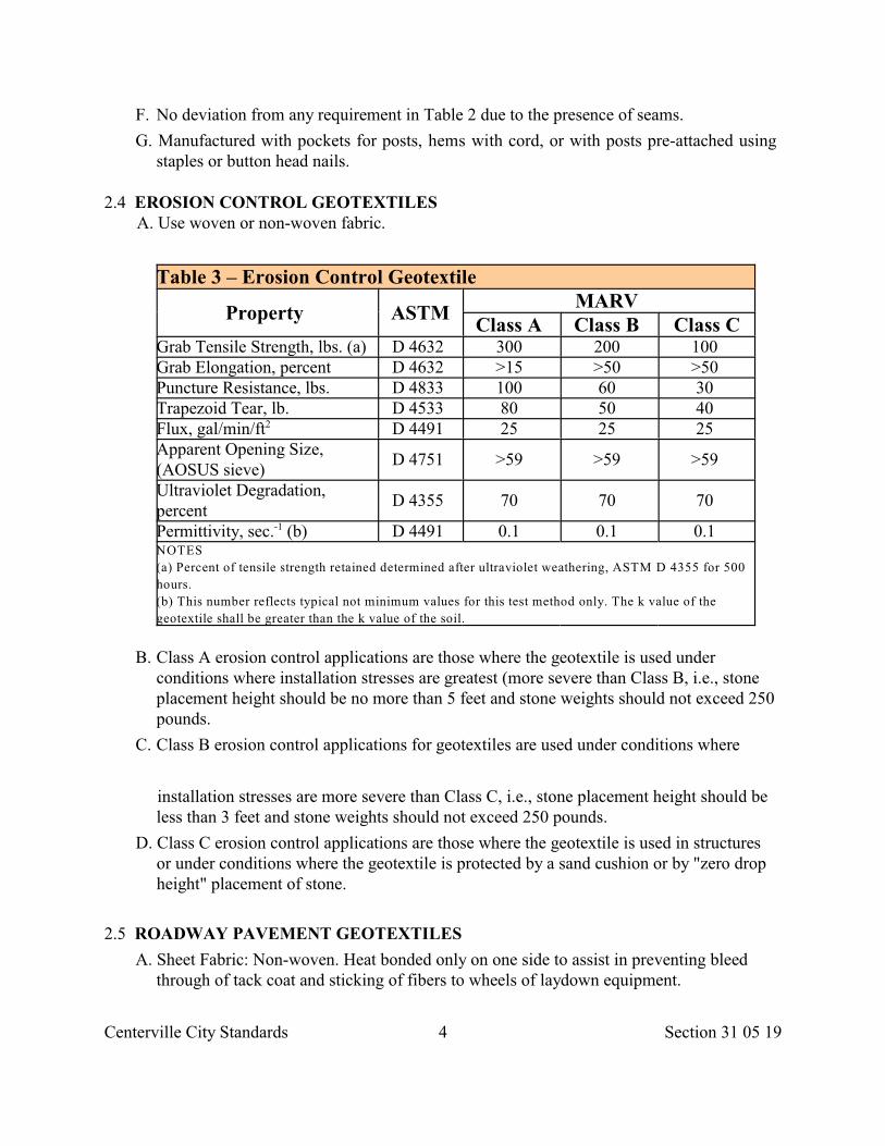
Centerville City Standards 4 Section 31 05 19
F. No deviation from any requirement in Table 2 due to the presence of seams.
G. Manufactured with pockets for posts, hems with cord, or with posts pre-attached usingstaples or button head nails.
2.4 EROSION CONTROL GEOTEXTILES A. Use woven or non-woven fabric.
Table 3 – Erosion Control Geotextile
Property ASTMMARV
Class A Class B Class CGrab Tensile Strength, lbs. (a) D 4632 300 200 100 Grab Elongation, percent D 4632 >15 >50 >50 Puncture Resistance, lbs. D 4833 100 60 30 Trapezoid Tear, lb. D 4533 80 50 40 Flux, gal/min/ft D 4491 25 25 25 2
Apparent Opening Size,(AOSUS sieve)
D 4751 >59 >59 >59
Ultraviolet Degradation,percent
D 4355 70 70 70
Permittivity, sec. (b) D 4491 0.1 0.1 0.1 -1
NOTES
(a) Percent of tensile strength retained determined after ultraviolet weathering, ASTM D 4355 for 500
hours.
(b) This number reflects typical not minimum values for this test method only. The k value of the
geotextile shall be greater than the k value of the soil.
B. Class A erosion control applications are those where the geotextile is used underconditions where installation stresses are greatest (more severe than Class B, i.e., stoneplacement height should be no more than 5 feet and stone weights should not exceed 250pounds.
C. Class B erosion control applications for geotextiles are used under conditions where
installation stresses are more severe than Class C, i.e., stone placement height should beless than 3 feet and stone weights should not exceed 250 pounds.
D. Class C erosion control applications are those where the geotextile is used in structuresor under conditions where the geotextile is protected by a sand cushion or by "zero dropheight" placement of stone.
2.5 ROADWAY PAVEMENT GEOTEXTILES
A. Sheet Fabric: Non-woven. Heat bonded only on one side to assist in preventing bleedthrough of tack coat and sticking of fibers to wheels of laydown equipment.
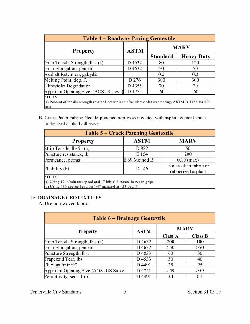
Centerville City Standards 5 Section 31 05 19
Table 4 – Roadway Paving Geotextile
Property ASTMMARV
Standard Heavy DutyGrab Tensile Strength, lbs. (a) D 4632 80 120 Grab Elongation, percent D 4632 50 50 Asphalt Retention, gal/yd2 0.2 0.3 Melting Point, deg. F. D 276 300 300 Ultraviolet Degradation D 4355 70 70 Apparent Opening Size, (AOSUS sieve) D 4751 60 60 NOTES
(a) Percent of tensile strength retained determined after ultraviolet weathering, ASTM D 4355 for 500
hours.
B. Crack Patch Fabric: Needle-punched non-woven coated with asphalt cement and arubberized asphalt adhesive.
Table 5 – Crack Patching Geotextile
Property ASTM MARV Strip Tensile, lbs/in (a) D 882 50 Puncture resistance, lb E 154 200 Permeance, perms E 69 Method B 0.10 (max)
Pliability (b) D 146 No crack in fabric orrubberized asphalt
NOTES
(a) Using 12 in/min test speed and 1” initial distance between grips.
(b) Using 180 degree bend on 1/4" mandrel at –25 deg. F.
2.6 DRAINAGE GEOTEXTILESA. Use non-woven fabric.
Table 6 – Drainage Geotextile
Property ASTM MARV
Class A Class B Grab Tensile Strength, lbs. (a) D 4632 200 100 Grab Elongation, percent D 4632 >50 >50 Puncture Strength, lbs. D 4833 60 30 Trapezoid Tear, lbs. D 4533 50 40 Flux, gal/min/ft2 D 4491 25 25 Apparent Opening Size,(AOS -US Sieve) D 4751 >59 >59 Permittivity, sec. -1 (b) D 4491 0.1 0.1
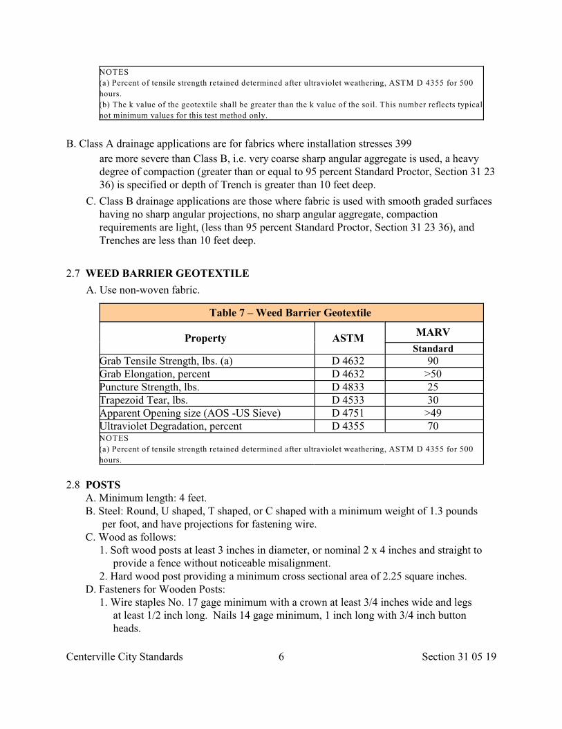
Centerville City Standards 6 Section 31 05 19
NOTES
(a) Percent of tensile strength retained determined after ultraviolet weathering, ASTM D 4355 for 500
hours.
(b) The k value of the geotextile shall be greater than the k value of the soil. This number reflects typical
not minimum values for this test method only.
B. Class A drainage applications are for fabrics where installation stresses 399
are more severe than Class B, i.e. very coarse sharp angular aggregate is used, a heavydegree of compaction (greater than or equal to 95 percent Standard Proctor, Section 31 2336) is specified or depth of Trench is greater than 10 feet deep.
C. Class B drainage applications are those where fabric is used with smooth graded surfaceshaving no sharp angular projections, no sharp angular aggregate, compactionrequirements are light, (less than 95 percent Standard Proctor, Section 31 23 36), andTrenches are less than 10 feet deep.
2.7 WEED BARRIER GEOTEXTILE
A. Use non-woven fabric.
Table 7 – Weed Barrier Geotextile
Property ASTM MARV
Standard Grab Tensile Strength, lbs. (a) D 4632 90 Grab Elongation, percent D 4632 >50 Puncture Strength, lbs. D 4833 25 Trapezoid Tear, lbs. D 4533 30 Apparent Opening size (AOS -US Sieve) D 4751 >49 Ultraviolet Degradation, percent D 4355 70 NOTES
(a) Percent of tensile strength retained determined after ultraviolet weathering, ASTM D 4355 for 500
hours.
2.8 POSTS A. Minimum length: 4 feet. B. Steel: Round, U shaped, T shaped, or C shaped with a minimum weight of 1.3 pounds per foot, and have projections for fastening wire. C. Wood as follows:
1. Soft wood posts at least 3 inches in diameter, or nominal 2 x 4 inches and straight to provide a fence without noticeable misalignment. 2. Hard wood post providing a minimum cross sectional area of 2.25 square inches. D. Fasteners for Wooden Posts:
1. Wire staples No. 17 gage minimum with a crown at least 3/4 inches wide and legs at least 1/2 inch long. Nails 14 gage minimum, 1 inch long with 3/4 inch button heads.
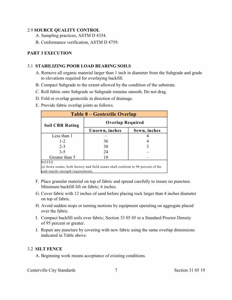
Centerville City Standards 7 Section 31 05 19
2.9 SOURCE QUALITY CONTROL A. Sampling practices, ASTM D 4354.
B. Conformance verification, ASTM D 4759.
PART 3 EXECUTION
3.1 STABILIZING POOR LOAD BEARING SOILS
A. Remove all organic material larger than 1 inch in diameter from the Subgrade and gradeto elevations required for overlaying backfill.
B. Compact Subgrade to the extent allowed by the condition of the substrate.
C. Roll fabric onto Subgrade so Subgrade remains smooth. Do not drag.
D. Fold or overlap geotextile in direction of drainage.
E. Provide fabric overlap joints as follows.
Table 8 – Geotextile Overlap
Soil CBR Rating Overlap Required
Unsewn, inches Sewn, inches Less than 1
1-22-33-5
Greater than 5
–36302418
443––
NOTES
(a) Sewn seams, both factory and field seams shall conform to 90 percent of the
grab tensile strength requirements.
F. Place granular material on top of fabric and spread carefully to insure no puncture.Minimum backfill lift on fabric; 6 inches.
G. Cover fabric with 12 inches of sand before placing rock larger than 4 inches diameteron top of fabric.
H. Avoid sudden stops or turning motions by equipment operating on aggregate placedover the fabric.
I. Compact backfill soils over fabric; Section 33 05 05 to a Standard Proctor Densityof 95 percent or greater.
J. Repair any puncture by covering with new fabric using the same overlap dimensionsindicated in Table above.
3.2 SILT FENCE
A. Beginning work means acceptance of existing conditions.
Centerville City Standards 8 Section 31 05 19
B. The quantity of temporary silt fences may be increased, decreased, or eliminated entirelyat Developer's discretion. Maintain the silt fence until the Work is accepted or until thefence and silt accumulations are removed.
C. Clear area of any debris and obstructions that may damage geotextile.
D. Place post in all low points.
E. Install posts a maximum of 8 feet apart with at least 18 inches in the ground. If notpossible to achieve depth, secure posts to prevent overturning.
F. Attach filter fabric by wire, cord, pockets, staples, nails, or other effective means.
1. When using a wire support fence, provide at least 6 horizontal wires with a minimumof 12 gage wire. Space vertical wires 6 inches maximum. Secure geotextile to the upslope side of the post. Extend wire into the Trench a minimum of 2 inches and extenda maximum or 36 inches above the ground surface.
G. Install fabric so 6 to 8 inches of fabric is left at the bottom to be buried. Splice togetheronly at support posts with any a minimum overlap of 18 inches. Extend buried portion 6inches deep and the rest upstream of the fabric fence.
H. Sediment Removal: Remove sediment before deposit reaches 1/2 of the height of the siltfence, or extend height of silt fence. After removal of sediment, dress landscape.
I. Schedule of Locations: Typical locations include the toe of fill slopes, the downhill sideof fill slopes, the downhill side of large cut areas, and at natural drainage areas. Limitgeotextile materials to handle an area equivalent to 1,000 square feet per 10 feet offence. Use caution should site slope be steeper than 1:1, and water flow rates exceed 1cubic foot per second per 10 feet of fence face.
3.3 EROSION CONTROL
A. Install fabric in locations shown on the Drawings.
B. Unless otherwise specified, the geotextile shall be overlapped a minimum of 2 feetat all longitudinal and transverse joints, or the geotextile shall be sewn.
C. If overlapped, the geotextile shall be placed so that the upstream sheet overlaps thedownstream sheet.
D. For placement on slopes, each strip shall overlap the next downhill strip.
E. The geotextile shall be anchored using key Trenches or aprons at the crest and toe ofthe slope.
F. Pins, usually 18 inches in length, may be helpful in securing the geotextile duringinstallation.
G. Repair: Place patch over damaged area and extend 3 feet beyond the perimeter of thetear or damage.
3.4 ROADWAY PAVING FABRICS
Centerville City Standards 9 Section 31 05 19
A. Preparing Asphalt Concrete Surface:
1. Brush road surface clean of debris, dust and gravel. Remove all water from surface and allow to dry.
2. Patch holes and level any uneven areas with asphalt concrete. 3. Fill cracks between 1/8 inch to 1/2 inch with asphalt cement. Allow cement to cure
prior to geotextile placement. 4. Clean cracks larger than 1/2 inch to a depth of 3 inches and fill with asphalt concrete.
Where Pavement is severely cracked, rutted, deformed or distressed, secure approval for providing an asphalt concrete leveling course prior to geotextile placement.
B. Tacking Asphalt Surface for Pavement Fabric: Use tack asphalt recommended byfabric manufacturer. Apply tack as follows:
1. Dry Pavement surface; 0.20 to 0.30 gallons per square yard. Within streetintersections, on steep grades and in zones where vehicle speed changes arecommonplace, reduce the application rate to no less than 0.20 gallons per sq.yard.
2. Heavy duty fabrics; 0.30 to 0.40 gallons per square yard. 3. Provide a tack width equal to geotextile width plus 6 inches. 4. Apply tack only as far in advance of geotextile installation as is appropriate to insure a
tacky surface at the time of geotextile placement. 5. Allow tack time to cure with no moisture remaining prior to placing the geotextile and
overlay. 6. Clean excess tack material from the road surface.
C. Placement of Fabric:
1. Place paving fabric into the asphalt with a minimum amount of wrinkling or folding. Wrinkles or folds in excess of 1 inch shall be slit and laid flat.
2. Shingle-lap all transverse joints and slit folds or wrinkles in the direction of the paving operation.
3. Maximize geotextile contact with the Pavement surface by brooming or pneumatic rolling.
4. Additional hand-placed asphalt may be required at laps and repairs. D. Protection and Repair:
1. Do not allow traffic except necessary construction equipment and emergency vehicles to drive on the fabric.
2. Turn paver and other vehicles gradually and keep turning to a minimum to avoid movement and damage to the geotextile. Do not permit abrupt starts and stops.
3. Remove and replace damaged geotextile with the same type of geotextile, and shingle- lap the overlaps in the direction of paving. Restrict overlaps to a maximum of 6 inches.
3.5 SUBSURFACE DRAINAGE
A. Excavate Trench to size and depth indicated.
B. Cut fabric to width required and place in Trench. Prevent damage to geotextile.
C. Overlap geotextile 12 inches or the full width of the Trench, whichever is less at the topof the Trench.
Centerville City Standards 10 Section 31 05 19
D. Overlap successive pieces of geotextile a minimum of 12 inches in the direction offlow.
E. Place fill to hold fabric in place.
F. Repair any damage to geotextile by placing patches extending 3 feet in all directionsbeyond the damaged area.
3.6 WEED BARRIER A. Preparation:
1. Remove sharp objects, large stones and undesirable vegetation. 2. If placing geotextile over existing bed, cut an "X" over each plant and push geotextile
under plant base. If placing over new bed, roll geotextile over soil and cut an "X" for each plant hole. Fold excess geotextile under and cover with specified landscaping materials.
B. Surface Cover: Provide a minimum of 4 inches of cover on all areas on the geotextileunless otherwise specified by ENGINEER. If using large landscape rock, increasethickness of cover material over geotextile to 3 times the diameter of the largest rockmaterial. Do not leave any portion of geotextile exposed to direct sunlight.
C. Repair: Repair immediately. Clear the damaged area plus an additional 3 feet and applygeotextile patch.
D. Maintenance: Maintain surfaces and supply additional landscape materials wherenecessary, including areas affected by erosion.
3.7 FIELD QUALITY CONTROL
A. Reject fabric at the time of installation, if it has defects, rips, holes, flaws,deterioration, or damage incurred during manufacture, transportation, handling orstorage.
END OF SECTION
Centerville City Standards 11 Section 31 05 21
SECTION 31 05 21
GEOGRIDS/GEOCOMPOSITES
PART 1 GENERAL
1.1 SECTION INCLUDES A. Geogrid and geocomposite material requirements.
1.2 REFERENCES
A. ASTM D 4354: Standard Practice for Sampling of Geotextiles for Testing.
B. ASTM D 4759: Standard Practice for Determining Specification Conformance ofGeosynthetics.
C. ASTM D 4873: Standard Guide for Identification, Storage, and Handling ofGeotextiles.
D. ASTM D 5321: Standard Practice for Determining the Coefficient of Soil and Geosyntheticby Direct Shear.
E. ASTM D 6213: Standard Tests to Evaluate the Chemical Resistance of Geogrids to Liquids.
F. ASTM D 6637: Standard Test Method for Determining Tensile Properties of Geogrid.
G. FHWA-SA-96-071: Mechanically Stabilized Earth Walls and Reinforced Soil SlopesDesign and Construction Guidelines.
1.3 DEFINITIONS
A. Geocomposite: Fabric composed of a geogrid and geotextile.
B. MARV: Defined in Section 31 05 19.
1.4 SUBMITTALS
A. Geogrid sample.
B. Geocomposite sample
C. Manufacturer’s warranty.
D. Installer’s warranty.
1.5 DELIVERY STORAGE AND HANDLING
A. Label, handle and store product, ASTM D 4873.
B. Deliver product dry, in a plastic wrapping that protects the entire roll.
C. Protect product from ultraviolet light and temperature greater than 160 deg. F. untilapplication. Cover product within 14 days of deployment.
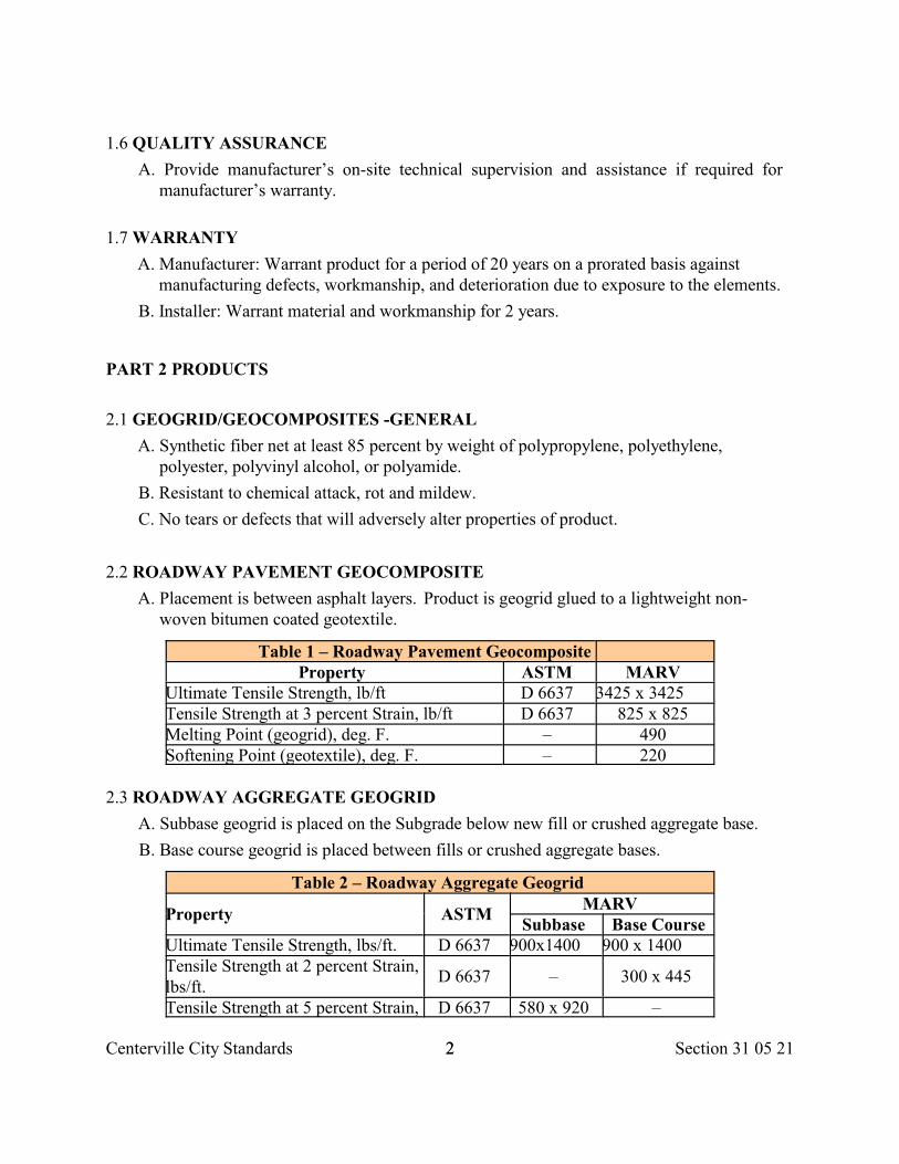
Centerville City Standards 22 Section 31 05 21
1.6 QUALITY ASSURANCE
A. Provide manufacturer’s on-site technical supervision and assistance if required formanufacturer’s warranty.
1.7 WARRANTY
A. Manufacturer: Warrant product for a period of 20 years on a prorated basis againstmanufacturing defects, workmanship, and deterioration due to exposure to the elements.
B. Installer: Warrant material and workmanship for 2 years.
PART 2 PRODUCTS
2.1 GEOGRID/GEOCOMPOSITES -GENERAL
A. Synthetic fiber net at least 85 percent by weight of polypropylene, polyethylene,polyester, polyvinyl alcohol, or polyamide.
B. Resistant to chemical attack, rot and mildew.
C. No tears or defects that will adversely alter properties of product.
2.2 ROADWAY PAVEMENT GEOCOMPOSITE
A. Placement is between asphalt layers. Product is geogrid glued to a lightweight non-woven bitumen coated geotextile.
Table 1 – Roadway Pavement Geocomposite Property ASTM MARV
Ultimate Tensile Strength, lb/ft D 6637 3425 x 3425 Tensile Strength at 3 percent Strain, lb/ft D 6637 825 x 825 Melting Point (geogrid), deg. F. – 490 Softening Point (geotextile), deg. F. – 220
2.3 ROADWAY AGGREGATE GEOGRID
A. Subbase geogrid is placed on the Subgrade below new fill or crushed aggregate base.
B. Base course geogrid is placed between fills or crushed aggregate bases.
Table 2 – Roadway Aggregate Geogrid
Property ASTMMARV
Subbase Base CourseUltimate Tensile Strength, lbs/ft. D 6637 900x1400 900 x 1400 Tensile Strength at 2 percent Strain,lbs/ft.
D 6637 – 300 x 445
Tensile Strength at 5 percent Strain, D 6637 580 x 920 –
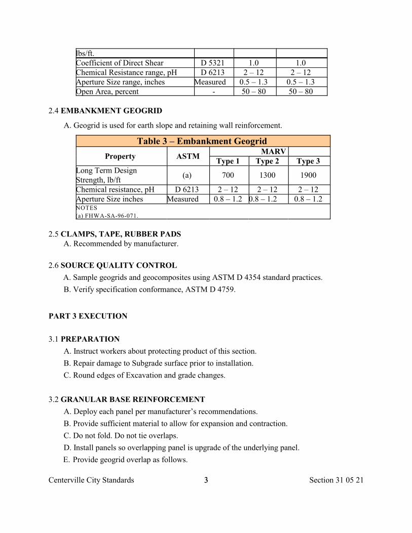
Centerville City Standards 33 Section 31 05 21
lbs/ft. Coefficient of Direct Shear D 5321 1.0 1.0 Chemical Resistance range, pH D 6213 2 – 12 2 – 12 Aperture Size range, inches Measured 0.5 – 1.3 0.5 – 1.3 Open Area, percent - 50 – 80 50 – 80
2.4 EMBANKMENT GEOGRID
A. Geogrid is used for earth slope and retaining wall reinforcement.
Table 3 – Embankment Geogrid
Property ASTMMARV
Type 1 Type 2 Type 3 Long Term DesignStrength, lb/ft
(a) 700 1300 1900
Chemical resistance, pH D 6213 2 – 12 2 – 12 2 – 12 Aperture Size inches Measured 0.8 – 1.2 0.8 – 1.2 0.8 – 1.2 NOTES
(a) FHWA-SA-96-071.
2.5 CLAMPS, TAPE, RUBBER PADS A. Recommended by manufacturer.
2.6 SOURCE QUALITY CONTROL
A. Sample geogrids and geocomposites using ASTM D 4354 standard practices.
B. Verify specification conformance, ASTM D 4759.
PART 3 EXECUTION
3.1 PREPARATION
A. Instruct workers about protecting product of this section.
B. Repair damage to Subgrade surface prior to installation.
C. Round edges of Excavation and grade changes.
3.2 GRANULAR BASE REINFORCEMENT
A. Deploy each panel per manufacturer’s recommendations.
B. Provide sufficient material to allow for expansion and contraction.
C. Do not fold. Do not tie overlaps.
D. Install panels so overlapping panel is upgrade of the underlying panel.
E. Provide geogrid overlap as follows.
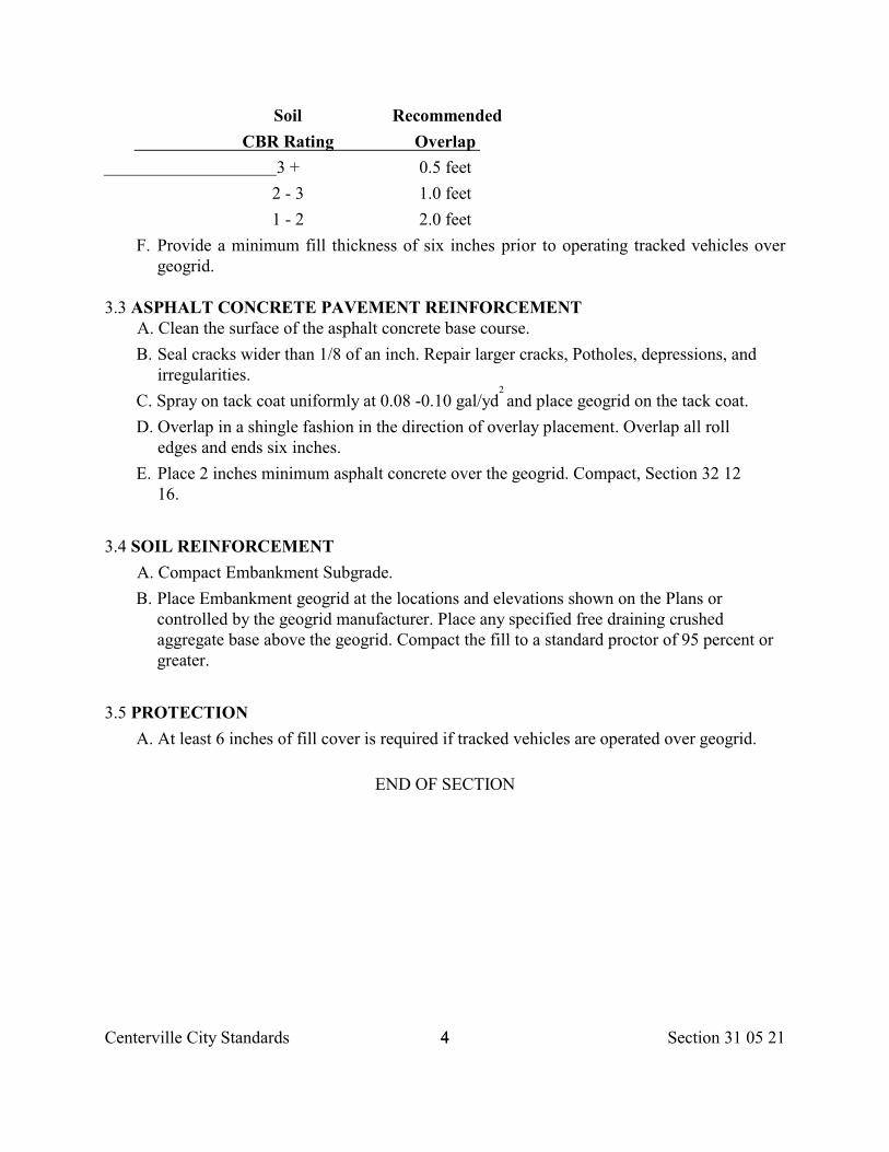
Centerville City Standards 44 Section 31 05 21
Soil Recommended
CBR Rating Overlap
3 + 0.5 feet
2 - 3 1.0 feet
1 - 2 2.0 feet
F. Provide a minimum fill thickness of six inches prior to operating tracked vehicles overgeogrid.
3.3 ASPHALT CONCRETE PAVEMENT REINFORCEMENT A. Clean the surface of the asphalt concrete base course.
B. Seal cracks wider than 1/8 of an inch. Repair larger cracks, Potholes, depressions, andirregularities.
C. Spray on tack coat uniformly at 0.08 -0.10 gal/yd and place geogrid on the tack coat. 2
D. Overlap in a shingle fashion in the direction of overlay placement. Overlap all rolledges and ends six inches.
E. Place 2 inches minimum asphalt concrete over the geogrid. Compact, Section 32 1216.
3.4 SOIL REINFORCEMENT
A. Compact Embankment Subgrade.
B. Place Embankment geogrid at the locations and elevations shown on the Plans orcontrolled by the geogrid manufacturer. Place any specified free draining crushedaggregate base above the geogrid. Compact the fill to a standard proctor of 95 percent orgreater.
3.5 PROTECTION
A. At least 6 inches of fill cover is required if tracked vehicles are operated over geogrid.
END OF SECTION
Centerville City Standards Section 31 05 23.131
SECTION 31 05 23.13
FLOWABLE FILL FOR TRENCH EXCAVATION
PART 1 - GENERAL
1.1 SECTION INCLUDES
A. Measurement and payment, materials and placement of a flowable fill in all trenchexcavation done at utility street construction, or at other locations as shown on theplans or as directed by the Engineer.
PART 2 - PRODUCT
2.1 MATERIAL AND COMPOSITION
Flowable fill shall conform to the following requirements:
A. Portland Cement shall be Type I or II conforming tot he requirement of UDOTsubsection 718.01.
B. Fly ash shall meet requirements of ASTM C-618, Class F, except loss on ignitionshall not exceed 3% maximum, and shall come from a source approved by theEngineer.
C. The course and fine aggregate for flowable fill shall be natural sand consisting ofmineral aggregate particles. The gradation of this material shall be as follows:
Sieve Size % Passing 3/4 100 200 0-10
D. Composition: The cubic yard of mix shall be designed to meet the followingrequirements:
Minimum compressive strength (28 day) 50 PSIMaximum compressive strength (28 day) 150 PSIMinimum fly ash per cubic yard 300 lbsMinimum cement per cubic yard 50 lbsMaximum slump 10 inches
Centerville City Standards Section 31 05 23.132
PART 3 - EXECUTION
3.1 PLACEMENT OF MORTAR
A. The flowable fill shall be discharged from the ready mix truck by any reasonablemeans into the area to be filled. The flowable fill will have a minimum thicknessof 2'-0" and will be brought up to the bottom of the Bituminous Surface Course,unless otherwise stated on the plans.
3.2 UNIT PRICE - MEASUREMENT AND PAYMENT
A. Flowable fill will be measured by the cubic yard. The width and depth used in thecomputations shall be the measured width and depth not to exceed the plan widthand depth and the length will be the measured length.
END OF SECTION
Centerville City Standards 1 Section 31 11 00
SECTION 31 11 00
SITE CLEARING
PART 1 GENERAL
1.1 SECTION INCLUDES A. Removal of trees, stumps, roots, and tree debris. B. Clearing site of plant life, root systems and shrubs. C. Removal of fences, fence posts, mail box posts, and miscellany.
1.2 REFERENCES A. NAA: Pruning Standards for Shade Trees. B. Utah Shade Tree Pruning Standards.
1.3 QUALITY ASSURANCE
A. Provide at least one person, who is familiar with NAA pruning standards for the type oftree involved, to be present during tree pruning operations.
1.4 SITE CONDITIONS
A. Repair or replace damaged trees and shrubs.
1.5 PROTECTION
A. Protect roots and branches of trees to remain.
B. Construct temporary barricading at tree's approximated drip line. Place continuousbarricades at least 3 feet high.
C. When setting posts, avoid damaging tree roots.
D. Do not permit heavy equipment or stockpiling of materials or debris within thebarricaded area, or permit earth surface to be changed.
E. Provide water and fertilizer to maintain existing trees.
PART 2 PRODUCTS
2.1 STUMP TREATMENT SOLUTION
A. Formulated to kill existing vegetation.
PART 3 EXECUTION
Centerville City Standards 2 Section 31 11 00
3.1 EXAMINATION A. The Drawings do not purport to show all trees and shrubs existing on site. B. Verify with City Engineer which plantings are to be removed or to remain. C. Tree root inspection: 1. Assist City Engineer by removing and replacing existing surface improvements. 2. Cost of removals and replacements will be paid for using existing payment prices,
or if none, then by using Modification prices. 3.2 PREPARATION
A. Locate utilities. Preserve utilities that are to remain in service.
B. Review work procedures with City Engineer.
C. Schedule work carefully with consideration for property owners and general public.
D. Before starting, arrange for the disconnection of all utility services that are to be removedor which interfere with work.
3.3 SITE CLEARING
A. Remove all vegetation to outside Excavation, fill slope lines, and limits of slope rounding.
B. Remove fences, posts, appurtenances, and miscellaneous objects.
3.4 TREE REMOVAL
A. Remove branches, limbs, and debris.
B. Remove stumps and roots to 18 inches below proposed grade.
C. For stumps larger than 6 inches caliper remove and treat as follows:
1. Remove chips and debris from around remaining stump. 2. Apply stump treatment solution in accordance with manufacturer's recommendations. 3. Do not allow chemical solution to mist, drip, drift, or splash onto adjacent ground
surfaces or desirable vegetation. 4. Replace any existing vegetation damaged or killed through improper use of
chemical.
END OF SECTION
Centerville City Standards 1 Section 31 23 16
SECTION 31 23 16
EXCAVATION
PART 1 GENERAL
1.1 SECTION INCLUDES A. Excavation and disposal of excavated materials.
B. Protection of existing facilities, utilities, and structures affected by excavation.
1.2 DEFINITIONS
A. Extra Excavation: Upper limit of Excavation is proposed excavation limit. Lower and lateral limits are as authorized by City Engineer.
B. Classified Excavation: The excavation of specified materials.
C. Incidental Excavation: Excavation done for Developer's benefit, excavation error,dewatering of Excavation, slough, or over-break.
D. Unclassified Excavation: The excavation of all materials encountered regardless of thenature, size, or manner in which they are removed. Presence of isolated boulders orRock fragments will not be sufficient cause to change classification of surroundingmaterials.
1.3 STORAGE AND HANDLING
A. Stockpile excavated material to cause a minimum of inconvenience to public andprovide for emergency services as necessary.
B. Provide free access to all existing fire hydrants, water and gas valves, and meters.
C. Provide free flow of storm water in all gutters, conduits, and natural water courses.
D. Utilize traffic control signs, markers, and procedures in product storage and handlingactivities.
E. Promptly remove other material from site.
1.4 SITE CONDITIONS
A. Prior to excavation, photograph existing surfaces along which work may take place inorder to determine, after construction is completed, whether any damage to existingimprovements occurred prior to construction operations.
B. Perform Incidental Excavation.
Centerville City Standards 2 Section 31 23 16
PART 2 PRODUCTS
2.1 MATERIALS FOR OVER EXCAVATED AREAS A. Common fill, Section 31 05 13. B. Crushed aggregate base, Section 32 11 23.
C. Stabilization fill, crushed aggregate base or common fill with maximum rectilinearparticle size of 2 inches.
D. Stabilization fabric, Section 31 05 19.
PART 3 EXECUTION
3.1 PREPARATION
A. Use white paint and mark the proposed Excavation.
B. Call the one-call center and wait the required amount of time. Color of one call centermarks indicate the following.
1. White: Proposed Excavation 2. Pink: Temporary survey markings 3. Red: Electric power lines, cables, conduit and lighting cables 4. Yellow: Gas, oil, steam, Petroleum or gaseous materials 5. Orange: Communications, alarm, signal, cables or conduits. 6. Blue: Potable water. 7. Purple: Reclaimed Water, irrigation and slurry lines 8. Green: Sewer and storm drain lines
3.2 PROTECTION
A. Identify required lines, grades, contours, and benchmarks.B. Pothole, expose or otherwise locate utilities as necessary to give utility company at least
4 days notice to protect, preserve, or relocate a utility that interferes with or may bedamaged by excavation work.
C. Where utilities or structures conflict with design grades, report conflict to the appropriateutility company and City Engineer 14 days prior to the initiation of work within theconflict area.
D. For temporary controls, refer to Section 01 57 00. E. Support and protect from damage any existing facility and structure that exists in, passes
through, or passes under the site. F. No Contract Time extension shall be granted and no additional compensation shall be
made if CONTRACTOR fails to pothole and identify buried utilities or structureswhich conflict with the Work.
3.3 TOPSOIL
Centerville City Standards 3 Section 31 23 16
A. Excavate topsoil only to depth that will preserve topsoil quality. B. Do not mix topsoil with subsoil during stockpiling or spreading.
3.4 LANDSCAPE SPRINKLER SYSTEMS
A. Protect existing landscape sprinkler systems.
B. When disturbance of existing sprinkler system is required, interrupt and repair system sooperation of system is maintained.
3.5 SHORING
A. .Slope, shore, sheet, brace or otherwise support Excavations over 4 feet deep, Section 3141 00.
B. When soil conditions are unstable, Excavations shallower than 4 feet deep must alsobe sloped, supported or shored.
3.6 DEWATERING
A. Keep Excavation free from surface and ground water.
B. If ground water table is in the intended construction operations, dewater Excavations.
C. If there are no olfactory or visual indications of contamination in the water, dischargeaccording to requirements of Federal, State or local agency having jurisdiction.
D. If any evidence of contamination in the water, based on olfactory or visual indications,cease excavation work until potential risks are evaluated. During evaluation, handlewater as a contaminated material.
E. Pay for damages and costs resulting from dewatering operations.
3.7 GENERAL EXCAVATION REQUIREMENTS
A. Excavate topsoil from areas to be relandscaped or regraded and other marked areas.
B. Excavate site to line and grade indicated.
C. Carefully excavate soils in vicinity of buried utility marks placed by the one-call center.
D. Where soil has been softened or eroded by flooding or hardened by drying duringunfavorable weather, rework all damaged areas or replace with approved material.
E. Notify City Engineer of unexpected subsurface conditions.
F. Underpin adjacent structure, service utilities and pipe chases that may be damaged byExcavation work.
G. Protect Excavation walls as required. If conditions permit, slope Excavation Sides tomaintain a safe and clean working area. Remove loose materials.
H. Where City Engineer deems Subgrade material to be susceptible to frost heave orotherwise unsatisfactory, excavate additional depth.
Centerville City Standards 4 Section 31 23 16
3.8 ROADWAY EXCAVATION
A. In advance of setting line and grade stakes, clean Subgrade area of brush, weeds,vegetation, grass, and debris. Drain all depressions or ruts that contain water.
B. Backfill and compact over excavation.
3.9 STRUCTURAL AND LANDSCAPE EXCAVATION
A. Provide Shoring, cribs, cofferdams, caissons, pumping, bailing, draining, sheathing,bracing, and related items.
B. For piling work, coordinate special requirements for piling. Protect Excavationwalls.
C. If conditions permit, slope Excavation Sides as excavation progress. Maintain a safeand clean working area.
D. Support Excavations. Do not interfere with the bearing of adjacent foundations,pipelines, etc.
3.10 TRENCH EXCAVATION
A. Grade bottom of Trenches to provide uniform bearing surface.
B. If necessary, make bellholes and depressions required to complete joining of pipeor box.
C. Limit width of Trench excavations to the dimensions suitable for worker access per pipemanufacturer's recommendation. Provide enough space for compaction equipment.Notify ENGINEER if excavation operations exceed any indicated line and grade limits.
D. In public thoroughfares and regardless of Trench depth, limit length of open Trenchesto 200 lineal feet day or night. Provide barricading, Section 01 55 26. Protect Trenchesover night.
3.11 EXTRA EXCAVATION
A. If unstable material is encountered at the bottom or face of any Excavation, do notperform extra excavation without written consent.
B. Correct excavations beyond the specified lines and grades by filling and compacting theresulting voids with acceptable fill.
C. Volume of Excavation within any specified pay limit will be determined by the methodof average-end-areas in the original position.
3.12 TOLERANCE
A. Grading: Top surface of Subgrade = plus or minus 1 inch.
END OF SECTION
Centerville City Standards 1 Section 31 23 17
SECTION 31 23 17
ROCK REMOVAL
PART 1 GENERAL
1.1 SECTION INCLUDES
A. Requirements for Rock removal and the use of explosives to assist in Rock removal.
1.2 REFERENCES
A. NFPA 495: Code for the Manufacture, Transportation, Storage, and Use of ExplosiveMaterials.
1.3 DEFINITIONS
A. Rock: Solid mineral material that cannot be removed with equipment reasonablyexpected to be used in the Work without cutting, drilling or blasting.
1.4 SUBMITTALS
A. Submit proposed method of blasting, delay pattern, explosive types, type of blasting matcover, and intended Rock recovery method.
B. Submit photographs of existing site conditions and facilities in vicinity of Work prior toblasting.
1.5 QUALITY ASSURANCE
A. Seismic Survey Firm: Company specializing in seismic surveys with 2 yearsdocumented experience.
B. Explosive Firm: Company specializing in explosives for disintegration of Rock with 2years documented experience.
PART 2 PRODUCTS
2.1 EXPLOSIVES
A. Type recommended by explosives firm following seismic survey and required byauthorities having jurisdiction.
Centerville City Standards 2 Section 31 23 17
2.2 DELAY DEVICES
A. Type recommended by explosives firm.
2.3 BLASTING MAT MATERIALS
A. Type recommended by explosives firm.
PART 3 EXECUTION
3.1 PREPARATION
A. Verify site conditions and note irregularities affecting work of this section.
B. Obtain permits from authorities having jurisdiction before explosives are brought to siteor drilling is started.
C. Verify utility locations.
D. Beginning work of this section constitutes acceptance of existing conditions.
E. Comply with NFPA 495.
3.2 STORAGE OF BLASTING MATERIALS
A. Securely store all explosives in compliance with Laws and Regulations.
B. Mark all storage places clearly.
C. Where no local Laws or Regulations apply, provide storage not closer than 1,000 feetfrom any road, building, camping area or place of human occupancy.
3.3 ROCK REMOVAL -NONEXPLOSIVE METHOD
A. Cut away Rock at Excavation bottom to form level bearing.
B. Remove shaled layers to provide sound and unshattered base for foundations.
C. Remove and legally dispose of excess excavated material and debris off-site unlessindicated otherwise.
D. Correct unauthorized Rock removal.
3.4 ROCK REMOVAL -EXPLOSIVE METHOD
A. Provide a qualified explosives expert to act as an advisor and consultant during drillingand blasting operations.
B. Advise owners of adjacent buildings or structures and utility companies in writing priorto setting up seismographs. Describe blasting and seismic operations.
C. Obtain and pay for a seismic survey prior to Rock excavation to determine maximumcharges that can be used at different locations in area of Excavation without damaging
Centerville City Standards 3 Section 31 23 17
adjacent properties and utilities.
D. Provide seismograph monitoring during progress of blasting operations.
E. Disintegrate and remove Rock from excavation operations.
END OF SECTION
Centerville City Standards 1 Section 31 23 23
SECTION 31 23 23
BACKFILLING FOR STRUCTURES
PART 1 GENERAL
1.1 SECTION INCLUDES A. Structural backfill materials. B. Structural backfilling requirements.
1.2 SUBMITTALS
A. Submit maximum laboratory dry density and optimum laboratory moisture contentfor: 1. Subgrade material, and 2. Each type of fill to be used.
B. Upon ENGINEER's request, submit a written quality control Inspections and testingreport describing source and field quality control activities performed byCONTRACTOR and its Supplier.
1.3 QUALITY ASSURANCE
A. Do not change material sources, or aggregate without City Engineer's knowledge.
B. Reject backfill material that does not comply with requirements specified in this section.
1.4 STORAGE
A. Safely stockpile backfill materials.
B. Separate differing materials, prevent mixing, and maintain optimum moisture contentof backfill materials.
C. Avoid displacement of and injury to Work while compacting or operatingequipment.
D. Movement of construction machinery over Work at any stage of construction issolely at Developer's risk.
1.5 SITE CONDITIONS
A. Do not place, spread, or roll any backfill material over material that is damaged bywater. Remove and replace damaged material.
B. Control traffic and erosion. Keep area free of trash and debris. Repair settled, eroded,and rutted areas.
C. Reshape and compact damaged structural section to required density.
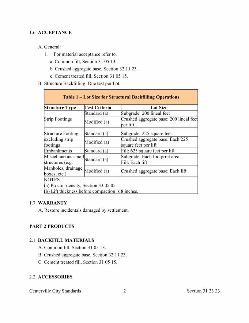
Centerville City Standards 2 Section 31 23 23
1.6 ACCEPTANCE
A. General:
1. For material acceptance refer to.
a. Common fill, Section 31 05 13.
b. Crushed aggregate base, Section 32 11 23.
c. Cement treated fill, Section 31 05 15.
B. Structure Backfilling: One test per Lot.
Table 1 – Lot Size for Structural Backfilling Operations
Structure Type Test Criteria Lot Size
Strip Footings Standard (a) Subgrade: 200 lineal feet
Modified (a) Crushed aggregate base: 200 lineal feetper lift.
Structure Footingexcluding stripfootings
Standard (a) Subgrade: 225 square feet.
Modified (a) Crushed aggregate base: Each 225square feet per lift
Embankments Standard (a) Fill: 625 square feet per lift Miscellaneous smallstructures (e.g.Manholes, drainageboxes, etc.)
Standard (a) Subgrade: Each footprint area Fill: Each lift
Modified (a) Crushed aggregate base: Each lift
NOTES (a) Proctor density, Section 33 05 05 (b) Lift thickness before compaction is 8 inches.
1.7 WARRANTY
A. Restore incidentals damaged by settlement.
PART 2 PRODUCTS
2.1 BACKFILL MATERIALS
A. Common fill, Section 31 05 13.
B. Crushed aggregate base, Section 32 11 23.
C. Cement treated fill, Section 31 05 15.
2.2 ACCESSORIES
Centerville City Standards 3 Section 31 23 23
A. Water:
1. Make arrangements for sources of water during construction and make arrangements for delivery of water to site.
2. Comply with local Laws and Regulations at no additional cost to OWNER when securing water from water utility company.
PART 3 EXECUTION
3.1 PREPARATION A. Verify:
1. Stockpiled fill meets gradation requirements. 2. Foundation walls are braced to support surcharge forces imposed by backfilling
operations, areas to be backfilled are free of debris, snow, ice or water. . 3. Ground surface is not frozen.
B. If subgrade is not readily compactable secure written authorization for extra excavationand backfill, Section 31 23 16.
C. Identify required line, levels, contours, and datum.
D. Stake and flag locations of underground utilities.
E. Upon discovery of unknown utility or concealed conditions, notify City Engineer.
3.2 PROTECTION
A. Protect existing trees, shrubs, lawns, existing structures, fences, roads, sidewalks,paving, curb and gutter and other features.
B. Protect above or below grade utilities. Contact utility companies to repair damage toutilities. Pay all cost of repairs.
C. Protect Subgrade from desiccation, flooding and freezing.
D. Do not fill adjacent to structures until Excavation is checked by City Engineer.
E. Do not use compaction equipment adjacent to walls or retaining walls that may causewall to become over-stressed or moved from alignment.
F. Do not disturb or damage foundation perimeter drainage, foundation, damp-proofing,foundation waterproofing and protective cover, or utilities in Trenches.
G. Restore any damaged structure to its original strength and condition.
3.3 LAYOUT
A. Maintain all benchmarks, control monuments and stakes, whether newly established bysurveyor or previously existing. Protect from damage and dislocation.
3.4 FOUNDATIONS AND SLABS ON GRADE
Centerville City Standards 4 Section 31 23 23
A. Place backfill materials in lifts not exceeding 8 inches after compaction.
B. Do not backfill against walls until concrete has obtained 14 day strength. Backfill against foundation walls simultaneously on each side.
C. Fill unauthorized excavations with material acceptable to City Engineer.
D. Do not damage adjacent structures or service lines.
E. Where flowable fill is used, use fill that flows easily and vibration for compaction is notrequired.
3.5 MODIFIED BACKFILL LAYER METHOD
A. Refer to Section 33 05 20.
3.6 COMPACTION
A. Compact backfill; Section 33 05 05 to the following maximum dry densities.
1. Under Footings: 98 percent. 2. Interior Crawl Spaces: 90 percent. 3. Interior Slab-On-Grade: 98 percent. 4. Side of Foundation Walls and Retaining Walls: a. Exterior: 95 percent. b. Interior: 98 percent. 5. Miscellaneous Structures: 95 percent.
3.7 CLEANING
A. Remove stockpiles from the site. Grade site surface to prevent free standing surfacewater.
B. Leave borrow areas clean and neat.
END OF SECTION
Centerville City Standards 1 Section 31 23 26
SECTION 31 23 26
COMPACTION
PART 1 GENERAL
1.1 SECTION INCLUDES A. Compaction of granular fill materials.
1.2 REFERENCES
A. ASTM D 698: Standard Test Method for Laboratory Compaction Characteristics of SoilUsing Standard Effort (12,400 ft-lbf/ft (600 kN-m/m )).
3 3
B. ASTM D 1557: Standard Test Methods for Laboratory Compaction Characteristics ofSoil Using Modified Effort (56,000 ft-lbf/ft (2,700 kN-m/m ))
3 3
C. ASTM D 2216: Standard Test Method for Laboratory Determination of Water (Moisture)Content of Soil and Rock.
D. ASTM D 2922: Standard Test Methods for Density of Soil and Soil-Aggregate inPlace by Nuclear Methods (Shallow Depth).
E. ASTM D 3017: Standard Test Method for Water Content of Soil and Rock in Place byNuclear Methods (Shallow Depth).
F. ASTM D 3282: Standard Practice for Classification of Soils and Soil-AggregateMixtures for Highway Construction Purposes.
G. ASTM D 3740: Standard Practice for Minimum Requirements for Agencies Engaged inthe Testing and/or Inspection of Soil and Rock as Used in Engineering Design andConstruction.
1.3 DEFINITIONS
A. A-1 Soil: Defined in ASTM D 3282.
B. Modified Proctor Density: The maximum laboratory density, as defined in anddetermined by ASTM D 1557 using procedure A, B or C as applicable.
C. Relative Density (or Relative Compaction): The ratio of field dry density to themaximum laboratory density expressed as a percentage.
D. Standard Proctor Density: The maximum laboratory density, as defined in and determinedby ASTM D 698 using procedure A, B or C as applicable.
1.4 QUALITY ASSURANCE
A. Use a laboratory that follows and complies with ASTM D 3740.
Centerville City Standards 2 Section 31 23 26
PART 2 PRODUCTS Not Used
PART 3 EXECUTION
3.1 COMPACTION
A. Moisten or dewater backfill material to obtain optimum moisture for compaction.
B. Correct deficient compaction conditions. Replace or repair materials and damagedfacilities.
C. When no density compactive effort is specified, compact the entire area to eliminateunstable zones.
3.2 FIELD QUALITY CONTROL
A. Testing: Perform control testing of materials. Perform additional testing at Developer’scost.
1. Because of changes in source of materials or proportions requested by Developer.
2. Because of Failure of materials to meet specification requirements. 3. For other testing services needed or required by Developer.
B. Report: For each material tested, record the following.
1. Vertical and horizontal location of the test. 2. Optimum laboratory moisture content. 3. Field moisture content. 4. Maximum laboratory dry density. 5. Field density. 6. Percent compaction results. 7. Certification of test results by testing agency.
C. Optimum Soil Density: Use ASTM D 2216 and the following industry standards.
1. For A-1 Soils: Use test method C of ASTM D 1557 (Modified Proctor) 2. For All Other Soils: Use test method C of ASTM D 698 (Standard Proctor).
D. Field Density:
1. Use ASTM D 3017 and test method C of ASTM D 2922 for shallow depth nuclear testing.
2. No density determinations are required on any material containing more than 65 percent material retained on the number 10 sieve or more than 60 percent material retained on the number 4 sieve. In lieu of reporting densities in such cases, report the sieve analysis to document the material type.
END OF SECTION
Centerville City Standards 1 Section 31 25 00
SECTION 31 25 00
EROSION AND SEDIMENTATION CONTROL
PART 1 GENERAL
1.1 SECTION INCLUDES
A. Erosion control and slope protection facilities including blankets or mulches.
B. Construction of drainage facilities to protect work area.
1.2 SUBMITTALS
A.Submit prior to using:
1. Sample of blanket or geotextile materials. 2. Mulch formula. 3. Grass mixture listing. 4. Plant list. 5. Geotextile manufacturer's certification.
B. Application rate of fiber mulches recommended by tackifiermanufacturer.
1.3 DELIVERY, STORAGE AND HANDLING
A. Deliver seed in original containers with certified germination test results showinganalysis of seed mixture, percentage of pure seed, year of production, and date ofpackaging. Damaged packages are not acceptable. Store seed free of moisture.
B. Deliver fertilizer in waterproof bags showing weight, chemical composition andname of manufacturer.
C. Deliver blanket in original wrapping showing name of manufacturer and product weight.
D. Deliver plant materials immediately prior to placement.
E. Replace plant when original root protection system (burlap bag wrap of earth ball, plasticcontainer with special plant bedder, etc.) has been broken or displaced prior to planting.
PART 2 PRODUCTS
2.1 MATERIALS
A. Riprap: Rock, Section 31 37 00.
B. Blankets: Uniform open weave jute, wood fiber, biodegradable or photodegradablesynthetic fiber matting.
C. Geotextiles: Refer to fabric in Section 31 05 19.
D. Erosion Control Vegetation Mats: Permanent three dimensional mats which allow for
Centerville City Standards 2 Section 31 25 00
revegetation where high water flows are expected.
E. Fiber Mulches: Straw, hay, wood or paper free from weeds or foreign matterdetrimental to plant life.
F. Mulch Binder: Vegetable based gel tackifier with growth stimulant.
G. Topsoil and Fertilizer: Refer to Section 31 05 13 and Section 32 92 00.
PART 3 EXECUTION
3.1 PREPARATION A. Remove foreign materials, roots, rocks, and debris. B. Grade to eliminate rough spots, and ponding areas. C. Grade soil to drain perimeter water away from protected areas. D. As applicable.
1. Temporary controls, Section 01 57 00. 2. Grass, Section 32 92 00.
3.2 SLOPE PROTECTION BLANKET A. Cover seeded slopes where grade is greater than 3 horizontal to 1 vertical with blanket.
Roll down over slopes carefully and loosely without stretching or pulling.
B. Lay blanket smoothly on prepared soil surface. Bury top end of each section in a narrowTrench. Leave 24 inches overlap from top roll over bottom roll. Leave 12 inches overlapover adjacent section.
C. Toe-in top end of each section in narrow Trench at least 12 inches deep. Toe-wrap fabricat bottom of slope.
D. Staple loosely the outside edges and overlaps.
E. In ditches, lay matting in upstream direction. Overlap and staple ends 6 inches withupstream section on top.
F. If natural drainage water traverses protected or controlled area; construct a channel orriprap according to Drawings and Section 31 37 00.
G. Lightly dress slopes with topsoil to ensure close contact between cover and soil.
H. Present alternative methods of protection for approval prior to starting any work.
3.3 GEOTEXTILE
A. Placement, Section 31 05 19.
3.4 MULCHES
A. Apply mulches at the rate indicated.
B. When installed with a tackifier, apply at the rate recommended by the tackifier Supplier.
Centerville City Standards 3 Section 31 25 00
3.5 SURFACE COVER A. Grass, Section 32 92 00. B. Ground cover, Section 32 93 13.
3.6 MAINTENANCE
A. Maintain surfaces and supply additional topsoil where necessary, including areasaffected by erosion.
B. Protect and repair geotextiles, Section 31 05 19.
C. Keep surface of soil damp only as necessary for seed germination.
D. Apply water slowly so surface of soil will not puddle and crust.
E. Replant damaged grass areas showing root growth Failure, deterioration, bare or thin spots,and eroded areas.
F. Re-fertilize 60 days after planting.
G. Remove weeds that are over 3 inches high.
END OF SECTION
Centerville City Standards 1 Section 31 31 19
SECTION 31 31 19
VEGETATION CONTROL
PART 1 GENERAL
1.1 SECTION INCLUDES A. Application of soil treatment to remove weed and vegetation.
1.2 SUBMITTALS
A. Submit certificate identifying composition of non-selective control herbicide.
PART 2 PRODUCTS
2.1 HERBICIDE
A. Water soluble herbicide for non-selective control of annual and perennial weeds.
PART 3 EXECUTION
3.1 MIXING
A. Mix herbicide solution in strict accordance with manufacturers instructions andapplicable Laws and Regulations.
3.2 APPLICATION
A. Execute all work in an orderly and careful manner with dueconsideration for surrounding plantings which are to remain.
B. Apply herbicide solution with a shield applicator. Do not allow solution to mist, drip,drift, or splash onto desirable vegetation.
C. Apply solution according to manufacturer's recommendations 7 days beforepreparation of surface to receive additional cover material. Do not add cover materialuntil City Engineer reviews spraying results.
D. Do not spray under windy or adverse weather conditions.
E. Replace portions of surrounding vegetation damaged or killed through this operation.
END OF SECTION
Centerville City Standards 1 Section 31 36 00
SECTION 31 36 00
GABIONS
PART 1 GENERAL
1.1 SECTION INCLUDES
A. Gabion for slope or bank protection and erosion control in open channels.
1.2 REFERENCES
A. ASTM A 313: Standard Specification for Chromium-Nickel Stainless and Heat-Resisting Steel Spring Wire.
B. ASTM A 641: Standard Specification for Zinc-Coated (Galvanized) Carbon SteelWire.
C. ASTM A 764: Standard Specification for Steel Wire, Carbon, Drawn Galvanized andGalvanized at Size for Mechanical Springs.
1.3 SUBMITTALS
A. Manufacturer's product data showing gabion wire twist or welded pattern, components tobe used, erection and component tolerances, overall layout, typical construction details,and construction procedures.
B. Design criteria recommended by manufacturer.
1.4 QUALITY ASSURANCE
A. Manufacturer of gabion structure to train and instruct construction personnelregarding installation of gabion.
B. Do not allow any gabion structure to deform during the backfill operation.
PART 2 PRODUCTS
2.1 MATERIALS
A. Gabions: Uniform hexagonal wire mesh woven in 2 or 3-1/2 twist pattern with openingsfabricated in such a manner as to be non--raveling and designed to provide the requiredflexibility and strength. The wire mesh shall have deformability sufficient to permit aminimum mesh elongation equivalent to 10 percent of the unstretched length of the meshtest section without reducing the gage or tensile strength of the individual wire strands tovalues less than those for similar wire, one gage smaller in diameter.
Centerville City Standards 2 Section 31 36 00
B. Wire: Class 3, ASTM A 641. 1. Wire Mesh Fabric: US gage 11 after galvanization. 2. Selvedges: US gage 9. 3. Binding and Connecting: US gage 13-1/2. 4. Tensile Strength: 60,000 -75,000 (psi). 5. Elongation: 12 percent maximum.
C. Polyvinyl Chloride Coated Galvanized Wire:
1. Wire Mesh Fabric: Same diameter as galvanized with an approximate overall diameter of 0.12785 inch (galvanized wire core plus PVC coating).
2. Selvedges: Same diameter as galvanized except, galvanized wire code to be US gage 10 (0.1338 inch with an approximate overall diameter of 0.15545 inch (galvanized wire core plus PVC coating).
3. Binding and Connecting: Same diameter as galvanized with an approximate overall diameter of 0.10825 inch (galvanized wire core plus PVC coating).
D. Fasteners: Resistant to a force of at least 900 pounds while still remaining in a locked and closed position.
1. Stainless steel, ASTM A 313 for PVC coated gabions. 2. Galvanized, ASTM A 764, Finish I, Class I, Type 3 with the same weight of coating as
specified in ASTM A 641. E. Stone: Hard, durable, graded from 4 inches to 8 inches diameter.
PART 3 EXECUTION
3.1 GABION ASSEMBLY
A. Assemble the base, lid, ends and sides into a single woven unit. If not woven thenconnect these members so that strength and flexibility at the connecting point is at leastequal to that of the mesh.
B. Where the length of the gabion exceeds 1-1/2 times its horizontal width, divide thegabion with diaphragms, of the same mesh and gage as the body of the gabion, into equalcells whose length does not exceed the horizontal width. Secure diaphragms in positionon the base section such that no field tying is required.
C. Tie all untied edges with binding wire. Loop wire tightly around every other meshopening along the seams such that every other mesh opening along the seams are singleand double loop alternating.
3.2 PLACEMENT
A. Place empty gabions into positions indicated. Tie each unit to the adjoining unit along thevertical reinforced edges and the top selvedges.
B. Tightly wire front and back of base of empty gabions to top of previously filled
Centerville City Standards 3 Section 31 36 00
gabions.
C. Stretch gabions to achieve better alignment and finish.
D. Position fasteners at 2 per foot of selvedge.
3.3 GABION FILLING A. Backfilling Gabion Structures 24 inches High or Greater:
1. Backfill each unit in 12 inches thick lifts. 2. At the completion of the first backfill lift, tie one connecting wire in each direction to
opposite face of each gabion cell. Loop and twist lock all connecting wires around 2 mesh openings.
3. At the completion of the second backfill lift, tie 2 connecting wires as above. 4. Continue above backfilling procedure until gabion structures are filled. 5. Tie gabion structure lid to the rest of the basket.
B. Backfilling Gabion Structures 18 inches High or Less:
1. Backfill each unit in lifts 1/2 the thickness of the gabion structure. 2. At the completion of the first backfill lift, tie 2 connecting wires in each direction.
Complete the wire tying and backfill operation as above.
END OF SECTION
Centerville Cit Standards 1 Section 31 37 00
SECTION 31 37 00
RIPRAP OR ROCK LINING
PART 1 GENERAL
1.1 SECTION INCLUDES A. Placement of loose riprap, hand-placed riprap, or grouted riprap.
1.2 REFERENCES
A. ASTM C 535: Standard Test Method for Resistance to Degradation of Large-SizeCoarse Aggregate by Abrasion and Impact in the Los Angeles Machine.
1.3 SUBMITTALS
A. Submit prior to use in the Work product data showing riprap source, gradation,aggregate wear and placement technique.
PART 2 PRODUCTS
2.1 AGGREGATE
A. Durable, angular, hard stone free from seams and cracks.
B. Graded in size to produce a reasonably dense mass.
C. The greatest dimension of 25 percent of the stones shall be at least, equal to but not morethan 1-1/2 times the thickness of riprap indicated.
D. The greatest dimension of 50 percent of the stone shall be at least 3/4, but not morethan 1-1/2 times the thickness of riprap indicated.
E. Not more than 10 percent of the aggregate shall have a dimension less than 0.1 timesthe thickness of riprap.
F. At least 95 percent of the stones shall have a minimum of 2 fractured or clean angularfaces.
2.2 ACCESSORIES
A. Portland cement grout, Section 03 61 00.
B. Geotextile fabric, Section 31 05 19.
Centerville Cit Standards 2 Section 31 37 00
2.3 SOURCE QUALITY CONTROL
A. Aggregate: Wear not greater than 40 percent when tested, ASTM C 535.
PART 3 EXECUTION
3.1 PREPARATION
A. Remove all brush, trees, stumps, and other objectionable materials and dress area to asmooth surface. Make Excavation to provide a firm foundation and protect againstundercutting. Secure approval prior to backfilling.
B. Install required geotextile in accordance with Section 31 05 19.
3.2 LOOSE-PLACED RIPRAP
A. Place stones to secure a Rock mass with the minimum thickness and height indicated.Manipulate Rock to secure a regular surface of graded size and mass stability.
3.3 HAND-PLACED RIPRAP
A. Place and bed the Rocks, one against the other, and key together. Fill irregularitiesbetween stones with suitable size spalls.
B. Place so that finished surface of riprap is even, tight, and true to line and grade. Extendriprap sufficiently below ground surface to secure a firm foundation.
3.4 GROUTED RIPRAP
A. Place riprap as indicated.
B. After wetting the stones, sweep sand or fine gravel into the interstices to fill to within 4inches of the outer surface of the riprap.
C. Fill the remaining volume of the interstices flush with a well-mixed grout.
D. Keep grout wet by sprinkling or covering with wet material for at least 3 days. Protectgrout from stream water or any other disturbance during this cure period.
E. Do not place grout in freezing weather.
END OF SECTION
Centerville City Standards 1 Section 31 41 00
SECTION 31 41 00
SHORING
PART 1 GENERAL
1.1 SECTION INCLUDES A. Shoring for open Excavations requiring a Protective System. B. Underpinning to stabilize adjacent structure.
1.2 DEFINITIONS
A. Accepted Engineering Practices: Those requirements or practices that are compatiblewith standards required by a duly licensed or recognized authority.
B. Benching: A method of protecting persons and property against cave-ins by excavatingthe Sides of an Excavation to form one or a series of horizontal levels or steps, usuallywith vertical or near-vertical surfaces between levels.
C. Excavation: Any man-made cut, cavity, or depression in an earth surface, includingTrenches, formed by earth removal and producing unsupported earth conditions(Sides). If installed forms or similar structures reduce the depth-to-width relationship,an excavation may become a Trench.
D. Failure: The permanent deformation or breakage of a structural member or connection; orthe collapse of all or part of an Excavation.
E. Protective System: Any recognized method of protecting persons and property againstcave-ins, the collapse of adjacent structures, or material that may fall or roll from an
Excavation Side or into an Excavation. Protective systems include Support Systems,Sloping and Benching systems and Shield systems.
F. Shield: A structure that is able to withstand the forces imposed on it by a cave-in andthereby protect persons and property within the structure without preventing a cave-in.Shields may be permanent structures or may be designed to be portable and moved alongas work progresses. Portable Shields used in Trenches are usually referred to as "trenchboxes" or "trench shields".
G. Shoring: A structure that supports the Sides of an Excavation and thereby protectspersons and property by preventing cave-ins.
H. Side: Vertical or inclined earth surface formed at the outer edges of an Excavation.
I. Sloping: A method of protecting persons and property against cave-ins by excavating toform Sides that are inclined away from the Excavation, the angle of incline being of sucha degree for the conditions of exposure that a cave-in will not occur.
J. Support System: A structure that protects persons and property by providing support toan adjacent structure, underground installation, or the Sides of an Excavation.
Centerville City Standards 2 Section 31 41 00
K. Trench: A narrow Excavation made below the surface of the ground. In general, thedepth is greater than the width, but the width of a trench is not greater than 15 feet.
L. Trench Box: See Shield.
M. Unfractured Rock: Rock that can be excavated with vertical Sides and remain intactwhile exposed. Fractured Rock is considered equivalent to unfractured Rock when thematerial on the Side or Sides of the Excavation is secured against cave-in or movementby Rock bolts, netting, or other means approved by a professional engineer.
1.3 DESIGN OF PROTECTIVE SYSTEMS
A. Design Support Systems, Shield systems, and the structural components of thesesystems, and Sloping and Benching systems to resist all loads that are intended to beimposed or transmitted to them.
B. Design system for any hydrostatic pressure in the Sides of an Excavation.
1.4 SUBMITTALS
A. Submit a Protective System plan when requested.
PART 2 PRODUCTS
2.1 MATERIALS
A. Developer's choice.
PART 3 EXECUTION
3.1 PREPARATION
A. Make safe or remove trees, surface encumbrances which are hazardous to Shoringoperations.
B. Provide adequate ventilation of Excavations.
C. Control dust and groundwater.
3.2 STABILITY OF ADJACENT STRUCTURES
A. Support adjoining buildings, walls, sidewalks, Pavements, or other structuresendangered by excavation operations.
B. Excavation below level of base of footing of any structural foundation or wall shall not bepermitted except as follows:
1. Underpinning or other Support Systems is provided to ensure stability of structure, or 2. Excavation is in Unfractured Rock, or
Centerville City Standards 3 Section 31 41 00
3. A professional engineer determines in writing that such work will in no way pose a hazard to persons and property or the integrity of the structure.
3.3 PROTECTION OF PERSONS AND PROPERTY
A. Protect from cave-ins. Install a Support System, by Sloping, by Benching, by use of aShield system, or by use of a combination of these methods.
B. Scale to remove loose material. Use Rock bolting, wire mesh, installation of protectivebarricades, or provide equivalent protection.
C. Stairway, Ladder, Ramp: Comply with OSHA.
D. Protect against cave-ins from vibratory loads adjacent to excavation operations.
3.4 INSPECTIONS
A. Inspect Excavations daily for evidence of possible cave-ins, indications of Failure ofProtective Systems, or other hazardous conditions.
B. Upon discovery of hazardous conditions, cease all work in the Excavations untiladditional precautions have been taken to ensure persons and property safety.
3.5 SHIELD SYSTEMS
A. Minimize the time the Sides of the Excavation remain unsupported.
B. Do not subject Shield systems to loads other than those considered for in their design.
C. Remove persons and property from Excavation when portable Shields are beingrelocated.
3.6 INSTALLATION AND REMOVAL OF SUPPORT SYSTEMS A. Do not overload Support Systems.
B. Install additional members to carry the loads imposed upon the Support System whentemporary removal of individual members is necessary.
C. When removing the Support System, release member by member slowly to avoid Failure ofthe remaining members or cave-ins.
D. Coordinate backfilling to minimize time an unsupported Excavation remains open.
END OF SECTION
Centerville City Standards 1 Section 32 01 05
SECTION 32 01 05
INFORMATION, REGULATORY, AND WARNING SIGNS
PART 1 GENERAL
1.1 SECTION INCLUDES
A. Information, regulatory, and warning signs but not street name signs or constructionsigns.
1.2 REFERENCES
A. MUTCD: Manual on Uniform Traffic Control Devices for Streets and Highways.
B. APA: American Plywood Association.
C. ASTM B 209: Standard Specification for Aluminum and Alumin-um-Alloy Sheetand Plate.
D. FS L-P 380: Plastic Molding Material Methacrylate.
E. FS L-S-300: Sheeting and Tape, Reflective: Nonexposed Lens.
F. PS 1: Construction and Industrial Plywood.
1.3 DEFINITIONS
A. For definition purposes, the various types of signs are identified by a combination ofletter and number. The letter represents the type of sign panel construction and thenumber represents the type of lettering and symbols to be used as follows:
1. Panel Type: a. Panel Type A: Reflectorized sheeting on sheet aluminum. b. Panel Type B: Reflectorized sheeting on plywood. 2. Letter Type: a. Letter Type 1: Reflectorized demountable cutout letters, symbols, and borders with
prismatic reflectors. b. Letter Type 2: Opaque legend and borders. c. Letter Type 3: Reflectorized permanently attached cutout letters, symbols, and
borders or reflectorized screen processed letters, symbols, and borders.
1.4 SUBMITTALS
A. Submit shop drawings of support structures prior to fabrication.
B. Submit sample of each color of reflective sheeting includingmanufacturer's name and product number.
Centerville City Standards 2 Section 32 01 05
PART 2 PRODUCTS
2.1 MATERIALS
A. Sheet Aluminum Sign Blank: 0.1 inch thick ASTM B 209 alloy 6061-T6.
B. Aluminum Extrusion Sign Blank: 0.1 inch thick ASTM B 209 alloy 6063-T5 and6063-T6.
C. Softwood Plywood Sign Blank: PS 1 Group 1 with each panel bearing initials DFPAGrade -Trademark of the American Plywood Association; painted to City Engineer'schoice of color unless indicated.
D. Posts: Galvanized structural steel, U-shaped, T-shaped, C-shaped, box-shaped, orround tube, Section 05 12 00, with 3/8 inch diameter mounting holes.
E. Fabricated Supports: Galvanized steel, Sections 05 12 00 and 05 05 10.
F. Reflective Sheeting: Reflective per FS L-S-300 requirements with 2,200 hours minimumdurability.
G. Nonreflective Sheeting: Nonchalking, weather resistant transparent plastic having aprotected adhesive backing and a smooth flat outer surface with glass spheresembedded within.
H. Prismatic Reflectors: Methyl methacrylate lens meeting FS L-P-380 requirementswith aluminum frame.
I. Bolts, Nuts, Accessories: Galvanized steel, Section 05 05 23.
J. Cast-in-place Concrete: Class 3000, Section 03 30 04.
2.2 COLORS AND FORMAT
A. Sign Colors and Format: Conform to MUTCD.
B. Provided colors of same reflectorized hue in daylight and night under artificial whiteillumination.
PART 3 EXECUTION
3.1 PREPARATION
A. Indentify utility location.
B. Excavation, Section 31 23 16.
3.2 INSTALLATION
A. Do not remove a sign that is being replaced until the new sign is placed and uncovered.
B. Unless indicated otherwise use clearance and locations shown in MUTCD. Install
Centerville City Standards 3 Section 32 01 05
posts plumb and in proper alignment.
C. Establish proper elevation and orientation of all signs, structures, and determine proper sign post lengths as dictated by construction slopes.
D. Cover signs that require temporary covering with a porous cloth or fiber material foldedover the sign edges and secured at the rear of the sign in such a manner that the sign isnot damaged. Maintain covering until oremoval.
E. Construct sign post foundations with concrete conforming to indicated dimensions.Finish foundations flush with or below natural ground.
F. Construct overhead support structures where indicated. Support sign by mounting postson anchor bolts placed in reinforced concrete foundations. Construct signs horizontaland perpendicular to roadway. The minimum allowable vertical clearance from the highpoint of Pavement is 16.5 feet.
3.3 WORKMANSHIP
A. Carefully fabricate and erect signs. Damage signs will be rejected.
B. Make all vertical joints and cuts flat and true.
C. Elevator bolts may be used or bolt holes relocated where conflict exists with signborder, legend, or copy.
D. Lay out and properly balance on the sign face all Type 1 legend and copy beforefastening. Plug holes left by shifting of copy or legend with the same type screw used tofasten the legend.
E. Wash all sign faces prior to Final Inspection.
END OF SECTION
Centerville City Standards 1 Section 32 01 06
SECTION 32 01 06
POST MOUNTED SIGNS
PART 1 GENERAL
1.1 SECTION INCLUDES A. Requirements for street name sign and components.
1.2 REFERENCES
A. ASTM B 209: Standard Specification for Aluminum andAluminum-Alloy Sheet and Plate.
B. FS L-S-300: Sheeting and Tape, Reflective: Nonexposed Lens.
PART 2 PRODUCTS
2.1 MATERIALS
A. Sheet Aluminum Sign Blanks: 0.1 inch thick ASTM B 209 alloy 6061-T6, of the heightindicated with length required to spell the street name (18, 24, 30, 36, 42, 48 inches).
B. Nonmetallic Sign Blanks: Fiberglass reinforced composite bonded with a thermosettingpolymer and the following properties.
1. Tensile strength (transverse), 5,000 psi minimum. 2. Tensile strength (longitudinal), 25,000 psi minimum. 3. Lengths as required to spell the street name (18, 24, 30, 36, 42, 48 inches). 4. Height as indicated.
C. Posts: Galvanized structural steel, U-shaped, T-shaped, C-shaped, box-shaped, orround tube with 3/8 inch diameter mounting holes.
D. Reflective Sheeting: Reflective per FS L-S-300 requirements with 2,200 hour minimumdurability.
E. Sign Lettering: White upper case and lower case letters, reverse silk screened onwhite with specified background color transparent ink.
F. Letter Composition: Spell out street name and give numerical coordinate on theright hand side; include neighborhood logo, if applicable, on the left hand side.Font as indicated.
G. Rail for Sign Blank: Tensile strength 40,000 psi minimum.
H. Bolts, Nuts, Accessories: Galvanized steel.
I. Cast-in-place Concrete: Class 3000, Section 03 30 04.
Centerville City Standards 2 Section 32 01 06
PART 3 EXECUTION
3.1 PREPARATION A. Identify utility location. B. Excavation, Section 31 23 16.
3.2 INSTALLATION A. Set posts 2 feet deep and anchored in concrete.
B. Provide 10 feet high clearance from the ground level to the bottom of sign.
C. Install posts plumb so closest edge of sign is 2 feet from vertical projection of the curbface at the point of curve (PC) of the intersection approach curb.
D. Restore all surfaces damaged during installation.
END OF SECTION
Centerville City Standards 1 Section 32 01 07
SECTION 32 01 07
RELOCATE POST MOUNTED SIGNS AND MAIL BOXES
PART 1 GENERAL
1.1 SECTION INCLUDES A. Relocate post mounted signs. B. Relocate mail boxes to supports which are approved by USPS.
1.2 REFERENCES A. USPS: United States Postal Service, mailbox requirements.
1.3 DEFINITIONS
A. Post Mounted Signs: Street name signs and traffic control signs such as regulatory signs,warning signs, guide signs, detour and closure signs.
PART 2 PRODUCTS
2.1 CONCRETE
A. Cast-in-place Concrete: Class 3000 minimum, Section 03 30 04.
2.2 MAIL BOX SUPPORTS
A. Wood: Salt treated fir, hemlock or pine for post, shelf and brace. Grade: No. 2 or better.
B. Metal: Galvanized or dark epoxy painted steel post, shelf and brace with no defects.
PART 3 EXECUTION
3.1 PREPARATION
A. Coordinate utility location.
B. Excavate, Section 31 23 16.
C. Reuse existing mail boxes, street signs and posts unless indicted otherwise.
3.2 EXISTING TRAFFIC CONTROL SIGNAGE
A. Maintain all existing street signs in full view of the intended traffic.
B. Coordinate relocations such that view of post mounted sign is maximize.
Centerville City Standards 2 Section 32 01 07
3.3 SIGN RELOCATION A. Maintain existing signs until construction requires removal. Coordinate with City
Engineer 24 hours in advance of removal of any sign.
B. Relocate existing street signs as indicated or ordered by the City Engineer.
C. Remove concrete from existing posts where posts are to be reused.
D. Protect new signs and posts until Project is accepted.
E. Reset post in concrete, 8 inches in diameter to the depth indicated or ordered by City
Engineer.
F. Completely fill and compact hole left by removing sign post. Match adjacent surface.
3.4 MAIL BOX RELOCATION A. Completely remove all designated mail box posts and footings.
B. Furnish and install new posts, shelf, and brace.
C. Relocate existing mail boxes indicated or ordered by the City Engineer.
D. Attach box firmly to shelf and post.
E. Repair any damage done to the mail box during moving or replace if irreparable to
City Engineer’s and mail box owner's satisfaction.
F. Compact soil around post and provide firm support.
G. Provide support for temporary mail box as required during construction, with temporary
mail box located in accordance with United States Postal Service requirements.
H. Restore original location of box to condition equivalent to adjacent area.
3.5 PAVEMENT MARKINGS A. Section 32 17 23.
END OF SECTION
Centerville City Standards Section 32 01 10
SECTION 32 01 10
RELOCATE FENCES AND GATES
PART 1 GENERAL
1.1 SECTION INCLUDES
A. Moving and resetting existing fences and gates to locations indicated or directed by CityEngineer.
PART 2 PRODUCTS
2.1 MATERIALS
A. Nails, Spikes and Staples: Galvanized steel for exterior, high humidity locations, andtreated wood, Size and type to suit applications.
B. Chain Link Fences and Gates: Section 32 31 13.
C. Wire Fences and Gates: Section 32 31 16.
D. Cast-in-place Concrete: Class 3000 minimum, Section 03 30 04.
PART 3 EXECUTION
3.1 PREPARATION
A. Coordinate locating utilities.
B. Excavation, Section 31 23 16.
3.2 INSTALLATION
A. Completely remove all existing posts, footings, wires, gates, and other items used infencing.
B. Remove concrete on posts. Reuse posts, wire, and gates from existing fence unlessdirected otherwise by City Engineer.
C. Replace any fencing materials and gates that are damaged, lost, or broken during fenceand gate relocations. Provide new materials as required which meets Specifications,for fence and gates of the same type.
D. Set relocated fences and gates straight and true.
E. Fill in old post holes unless they become part of new construction.
F. Reset posts in concrete, 8 inches in diameter to depth indicated or 2 feet minimum.
END OF SECTION
Centerville City Standards 1 Section 32 01 13
SECTION 32 01 13
SLURRY SEAL
PART 1 GENERAL
1.1 SECTION INCLUDES
A. Stone and paving asphalt slurry evenly spread as a roadway surface treatment.
1.2 REFERENCES
A. ASTM C 88: Standard Test Method for Soundness of Aggregates by use of Sodium Sulfateor Magnesium Sulfate.
B. ASTM C 117: Standard Method of Test for Amount of Material Finer Than 0.075 mmSieve in Aggregate.
C. ASTM C 131: Standard Test Method for Resistance to Degradation of Small-Size coarseAggregate by Abrasion and Impact in the Los Angeles Machine.
D. ASTM C 136: Standard Method for Sieve Analysis of Fine and Coarse Aggregates.
E. ASTM D 242: Standard Specification for Mineral Filler for Bituminous Paving Mixtures.
F. ASTM D 1664: Standard Test Method for Coating and Stripping of Bitumen-AggregateMixtures.
G. ASTM D 2419: Standard Test Method for Sand Equivalent Value of Soils and FineAggregate.
H. ASTM D 3319: Standard Test Method for Accelerated Polishing of Aggregates Usingthe British Wheel.
I. ASTM D 3628: Standard Practice for Selection and Use of Emulsified Asphalts.
J. ASTM D 3910: Standard Practices for Design, Testing, and Construction of SlurrySeal.
K. ASTM D 5821: Standard Test Method for Determining the percentage of FracturedParticles in Coarse Aggregate.
1.3 SUBMITTALS
A. Traffic control plan, Section 01 55 26.
B. Mix Design: 10 days prior to use, submit proportions of aggregate, filler, water andemulsions in the mix.
C. Equipment: Submit list of construction equipment to be used.
D. Asphalt Bill of Lading: Identify. 1. Weight of asphalt.
Centerville City Standards 2 Section 32 01 13
2. Weight of emulsified asphalt (after water has been added). 3. Paving asphalt complies with Section 32 12 03 requirements.
E. Quality Control Report: Upon City Engineer's request, submit a written quality controlinspections and testing report describing source and field quality control activitiesperformed by Developer's Supplier and Developer.
1.4 QUALITY ASSURANCE
A. Determine emulsion weights by mix design.
B. Do not change source of emulsified asphalt or aggregate without supportingchanges in mix design data.
C. Reject coating products that do not meet requirements of this Section.
1.5 WEATHER
A. Temperature:
1. Apply seal coat when air and roadbed temperatures in the shade are 45 deg. F. andrising.
2. Do not apply seal coat if pavement or air temperature is below 55 deg. F. and falling orif the finished product will freeze before 24 hours.
B. Moisture: Do not apply seal coat during rain, unsuitable weather, or if humidityprolongs curing.
1.6 NOTICE
A. Send written notice to residents and businesses within affected area at least 3 daysbefore applying slurry seal.
B. Indicate application time and when new surface can be used.
C. Warn of potential vehicle tow away and other construction issues affectingneighborhood..
D. Should work not occur on specified day, send a new notice.
1.7 ACCEPTANCE
A. General:
1. Acceptance is by Lot. Lot is specified below. 2. Opening slurry seal surface to traffic does not constitute acceptance.
B. Slurry Seal Materials:
1. Paving Asphalt: Acceptance is not specified in this Section. Refer to Section 32 12 03for acceptance.
2. Aggregate: Lot size is one day’s production with 300 tons sub-lots. Collect Samples
Centerville City Standards 3 Section 32 01 13
randomly from hauling equipment and test gradation, ASTM C 136. Lot will beacceptable if, a. Average gradation of each sieve for the Lot is within Target Grading Band for that
sieve, and b. Number of Samples in Lot with any sieve measurement outside of Target Grading
Band does not exceed 2, and c. No Sample varies from Target Grading Band by more than target tolerance on any
one sieve. C. Placement: Accepted on a block-by-block basis.
1. Mat Appearance: Installation must survive the following visual examinations.
a. No free liquid drains out of mat edges. b. No drag marks or streaking. c. No debonding due to road contaminants. d. Straight longitudinal edges with proper joints.
PART 2 PRODUCTS
2.1 PAVING ASPHALT
A. Tack Coat: Section 32 12 14.
B. Emulsified Asphalt: ASTM D 3628 or as indicated.
1. The residual asphalt shall constitute at least 60 percent of the emulsion by weight. 2. The Saybolt Furol viscosity of the emulsion at 77 deg. F., ASTM D 2170 shall not
exceed 50 seconds.
2.2 WATER
A. Clean, non-detrimental, free from harmful chemicals.
2.3 AGGREGATE
A. Material: Stone, slag, or other high quality particle or combination with the followingphysical properties. For heavy-duty surface applications use 100 percent crushed material. 1. Angularity (fractured faces): Greater than 80 percent of particles by weight with at
least 1 mechanically fractured faces or clean angular faces, ASTM D 5821. 2. Hardness (toughness): less than 35 percent wear of aggregate retained on the No. 8
sieve, ASTM C 131. 3. Weight Loss (soundness): less than 10 percent for combined coarse and fine aggregate
when subjected to 5 cycles of sodium sulfate, ASTM C 88. 4. Polishing: Greater than 38, ASTM D 3319. 5. Water Absorption: Less than 1.25 percent.
B. Gradation: ASTM C 136. Graded by dry weight on a percent passing basis. Gradation
Centerville City Standards 4 Section 32 01 13
must not vary from a high limit on one screen to a low limit on the next.
1. Targe Gradation Curve must lie within one of the following Master Grading Bands.Field samples shall not vary from the Target Gradation Curve by more than the TargetTolerance.
Table 1 - Master Grading Band and Target Tolerance Limit
US Sieve SizeMaster Grading Band Limits Target
TolerancePercentSS - I SS - II SS - III
3/8 in.No. 4No. 8No. 16No. 30No. 50No. 100No. 200
–100
90 – 10065 – 9040 – 6525 – 4215 – 3010 – 20
10090 – 10065 – 9045 – 7030 – 5018 – 3010 – 216 – 15
10070 – 9045 – 7028 – 5019 – 3412 – 287 – 185 – 15
–+/-5+/-5+/-5+/-5+/-4+/-3+/-2
NOTES
(a) Portion retained on the No. 4 sieve clean and free of clay coatings.
(b) Portion passing No. 200 sieve determined by ASTM C 117 includes mineral fillers.
2.4 MINERAL FILLER A. ASTM D 242.
B. Portland cement, hydrated lime, limestone dust, flyash, or aluminum sulfate to regulatesetting time and improve workability.
C. Limestone dust, fly ash, and rock dust to alter aggregate gradation.
2.5 MIX DESIGN
A. Proportioning: Use the consistency test of ASTM D 3910 to determine optimum ratio ofaggregate, filler, water, and emulsion.
B. Cure Time: Select to meet opening to traffic requirements.
C. Stripping: More than 90 percent of bituminous-coated particles retain asphalt coating,ASTM D 1664.
PART 3 EXECUTION
3.1 CONSTRUCTION EQUIPMENT
A. Use equipment capable of applying at least 15,000 square yards of material per day.
B. Use a continuous-flow mixing unit capable of accurately delivering a predeterminedportion of aggregate, water, and asphalt emulsion to the mixing chamber.
Centerville City Standards 5 Section 32 01 13
C. Prevent loss of slurry from the distributor by using a mechanical type squeegeedistributor equipped with flexible material in contact with the surface.
D. Provide a lateral control device and a flexible strike-off capable of being adjusted to lay theslurry at the mix design application rate.
3.2 PREPARATION
A. General:
1. Fat or bleeding Pavements may require scratch course application. 2. Cracked or porous pavements may require thin SSI slurry surface treatment. 3. Asphalt concrete inlay may be required in rut deformations.
B. Protection:
1. Protect trees, plants and other ground cover from damage. 2. Prune trees; Section 32 01 93. Allow equipment passage underneath. Repair tree
damage. 3. Install invert covers. 4. Mask Street Fixtures. 5. Protect curb, gutter, and sidewalk from spatter, mar or overcoat.
C. Traffic Control:
1. Control pedestrian and vehicular traffic, Section 01 55 26. Do not proceed withoutflaggers.
2. Protect slurry seal from traffic until cured. Cure time depends on type of asphalt,mixture characteristics and weather.
3. Do not apply lane marking tape or paint until layout and placement has been verifiedwith City Engineer.
D. Surface Repair: Patch holes, raveled areas, and low areas with asphalt concrete.
E. Crack Repair: Section 32 01 17.
1. Remove plant materials from cracks, edges and joints. 2. Blow cracks clean. 3. Seal cracks with crack pouring asphalt. Remove excess asphalt. 4. Allow crack seal to dry before applying slurry seal.
F. Cleaning:
1. Remove mud spots, sand, dust, oil, vegetation and other objectionable material. 2. Remove loose material that may cause drag marks. 3. Do not flush water over cracked Pavement.
G. Existing Roadway Striping: Use reflective tabs to mark roadway striping beforeapplying slurry seal.
H. Tack Coat: 1. Apply tack coat to high-absorbent, polished, oxidized, or raveled asphalt surfaces or to
concrete or brick surfaces. 2. Apply tack coat and pave over concrete Cover Collars.
Centerville City Standards 6 Section 32 01 13
3. Use the same asphalt emulsion as used in slurry seal application.
3.3 APPLICATION
A. General:
1. Application rates:
a. SS-I: 8 to 12 pounds per square yard. b. SS-II: 12 to 16 pounds per square yard. c. SS-III: 15 to 18 pounds per square yard. 2. Machine meter settings must match mix design. Water and mineral filler may be
changed per mix design; otherwise, a new mix design is required.
B. In the Spreader Box:
1. Do not exceed 4-minutes total mixing time. 2. No additional water. 3. No lumping, balling or unmixed aggregate. 4. No segregation of the emulsion and aggregate fines from the coarse aggregate. 5. No breaking of emulsion. 6. No overloading. Carry a sufficient amount of slurry in all parts of the spreader for
complete coverage. C. Spreading:
1. Dampen surface immediately prior to application of slurry seal. All surfaces are to beuniformly damp with no free water standing on the surface or in cracks when seal coatis applied.
2. If coarse aggregate settles to bottom of mix, remove slurry from pavement. 3. Except for lanes in which 2 or more boxes are used in tandem in placing slurry, do not
seal adjacent lanes until at least 2 hours have elapsed between placing one lane andthat of adjacent lane. Lap adjacent lanes at edges to provide complete sealing atoverlap.
4. When sealing short lanes, the waiting period may be omitted if the adjacent lane can besealed before emulsion in the previously sealed lane has broken and started to cure.
5. In areas where spreader box cannot be used, apply slurry by hand. D. Joints:
1. Correct any joints or cracks not filled by slurry seal. 2. Do not permit build-up on longitudinal or transverse joints. 3. Smooth thick spots before emulsion breaks so a uniform surface with no breaks or
discontinuities is obtained. E. Lines
1. Mask off end of streets and intersections to provide straight lines. 2. Make straight lines along lip of gutter and shoulders. No runoff on these areas
permitted. 3. Vary edge lines no more than 2 inches per 100 feet.
3.4 AFTER APPLICATION
Centerville City Standards 7 Section 32 01 13
A. Do not permit traffic on slurry seal until cured.
B. Leave no streaks caused by oversized aggregate, or buildup on squeegees.
C. Leave no holes, bare spots, or cracks.
D. The slurry, when cured shall present a uniform, skid-resistant appearance with all cracksfilled.
E. Do not apply traffic and lane marking tape or paint until layout and placement hasbeen verified by City Engineer.
3.5 FIELD QUALITY CONTROL
A. ASTM C 136. If tests show aggregate gradation non-compliance, either remove thematerial or blend in other aggregates to bring it into compliance. This may require a newmix design. Screening may be required at the stockpile to remove any defective material.
3.6 REPAIR
A. Remove spatter or mar from curb and gutter, sidewalk, guard rails and guide posts.
B. Remove slurry seal from Street Fixtures.
C. Make correction lines straight. Provide good appearance.
D. Fill any joints or cracks that are not covered by slurry seal. Leave no streaks, holes,bare spots, or cracks through which liquids or foreign matter could penetrate theunderlying Pavement.
E. Repair collateral damage caused by construction.
END OF SECTION
Centerville City Standards 1 Section 32 01 14
SECTION 32 01 14
CHIP SEAL
PART 1 GENERAL
1.1 SECTION INCLUDES
A. Paving asphalt and cover aggregate evenly spread as a uniform, skid-resistant roadwaysurface treatment.
1.2 REFERENCES
A. ASTM C 88: Standard Test Method for Soundness of Aggregates by use of Sodium Sulfateor Magnesium Sulfate.
B. ASTM C 117: Standard Method of Test for Amount of Material Finer Than 0.075 mmSieve in Aggregate.
C. ASTM C 131: Standard Test Method for Resistance to Degradation of Small-SizeCoarse Aggregate by Abrasion and Impact in the Los Angeles Machine.
D. ASTM C 136: Standard Method for Sieve Analysis of Fine and Coarse Aggregates.
E. ASTM C 142: Standard Test Method for Clay Lumps and Friable Particles inAggregates.
F. ASTM D 2170: Standard Test Method for Kinematic Viscosity of Asphalts (Bitumens).
G. ASTM D 3319: Standard Test Method for Accelerated Polishing of Aggregates Usingthe British Wheel.
H. ASTM D 3628: Standard Practice for Selection and Use of Emulsified Asphalts.
I. ASTM D 4791: Standard Test Method for Flat or Elongated Particles in Coarse Aggregate.
J. ASTM D 5821: Standard Test Method for Determining the percentage of FracturedParticles in Coarse Aggregate.
1.3 SUBMITTALS
A. Traffic control plan, Section 01 55 26.
B. Mix Design: Identify.
1. Type and grade of paving asphalt to be used (if not specified). 2. Aggregate gradation. 3. Asphalt/aggregate compatibility. 4. List of asphalt additives.
C. Equipment: Submit list of construction equipment to be used. D. Asphalt Bill of Lading: Identify.
1. Weight of asphalt.
Centerville City Standards 2 Section 32 01 14
2. Weight of emulsified asphalt (after water has been added).
E. Quality Control Report: Upon City Engineer's request, submit a written quality control
inspections and testing report describing source and field quality control activities
performed by Developer's Suppliers and Developer.
1.4 QUALITY ASSURANCE
A. Do not change source of supply of paving asphalt or aggregate without supporting changesin mix design.
B. Reject product that does not meet requirements of this Section.
C. Remove any product found defective after installation and install acceptable product.
1.5 WEATHER
A. Temperature:
1. Apply chip seal when air and roadbed temperatures in the shade are 70 deg. F. and rising.
2. Allow 4 weeks of warm weather cure time. This generally limits performance of work from May 15 to August 31.
3. Do not apply chip seal if Pavement surface is above 120 deg. F.B. Moisture: Do not apply chip seal during rain, unsuitable weather, or if humidity prolongs
curing.
1.6 NOTICE
A. Send written notice to residents and businesses within affected area 3 days before applyingchip seal.
B. Indicate application time and when new surface can be used.
C. Warn them of potential vehicle tow away and other construction issues affectingneighborhood.
D. Should work not occur on the specified day, send a new notice.
1.7 ACCEPTANCE
A. General:
1. Acceptance is by Lot. Lot size is specified below. 2. Opening chip seal surface to traffic does not constitute acceptance.
B. Material:
1. Paving Asphalt: Acceptance is not specified in this Section. Refer to Section 32 12 03 for acceptance.
2. Aggregate: Lot size is one day’s production with 500 tons sub-lots. Collect Samples randomly from the hauling equipment and test gradation, ASTM C 136. Lot will be acceptable if,
Centerville City Standards 3 Section 32 01 14
a. Average gradation of each sieve for Lot is within Target Grading Band for that sieve, and
b. Number of Samples in Lot with any sieve measurement outside of Target Grading Band does not exceed 2, and
c. 200 sieve gradation is not exceeded. 3. Price Adjustment: Aggregate gradation defect may be accepted if 5 percent price reduction is applied against Lot for each condition not met. Maximum price reduction for Lot is 10 percent.
C. Placement: Accepted on a block by block basis.
1. Paving Asphalt: Uniform with no ridging and no bare spots. 2. Aggregate: a. Embedment: After rolling and evaporation, random sampling reveals large particles
are embedded in the paving asphalt on their flat side to a depth of 50 percent to 70 percent.
b. Asphalt See-Through: Not more than 15 percent black (asphalt) can be seen through the newly laid and compacted rock chip after sweeping.
PART 2 PRODUCTS
2.1 PAVING ASPHALT
A. Cationic or anionic emulsion, Section 32 12 03.
B. Use any of the following additives to match aggregate particle charge, weatherconditions and mix design.
1. Anti-strip: To change or neutralize particle charges. 2. Enhancer: To promote greater film thickness on the aggregate. 3. High Float Agent: To improve temperature susceptibility of the asphalt and impart a
gel structure to the asphalt. 4. Polymer: To reduce stripping, improve coating, decrease temperature
susceptibility and increase stability of mix. 5. Rejuvenator: To adjust the penetration of the base asphalt or soften reclaimed asphalt.
2.2 COVER AGGREGATE
A. Material: 100 percent crushed stone, slag or other high quality particle or combination with the following physical properties.
1. Angularity (fractured faces): Greater than 60 percent of particles by weight with at least 2 mechanically fractured faces or clean angular faces, ASTM D 5821.
2. Hardness (toughness): Less than 30 percent wear of aggregate, ASTM C 131 unless specific aggregates having higher values are known to be satisfactory.
3. Weight Loss (soundness): For combined coarse and fine aggregate, ASTM C 88, a. Less than 12 percent using Na2SO4 b. Less than 18 percent using MgSO4
Centerville City Standards 4 Section 32 01 14
4. Polishing: Greater than 38, ASTM D 3319. 5. Flat or Elongated Particles: 10 percent maximum of a 3:1 ratio for material retained
above the 3/8 inch sieve, ASTM D 4791 6. Friable Particles: Less than 3 percent by weight of aggregate passing the No. 4 sieve,
ASTM C 142. B. Gradation: ASTM C 136. Graded by dry weight on a percent passing basis. Gradation must not vary from a high limit on one screen to a low on the next.
Table 1 – Master Grading Band and Target Tolerance Limits
Sieve Grade A Grade B Grade C 1/2 in 3/8 in. No. 4 No. 8 No. 16 No. 50 No. 200
100 85 – 100 0 – 20 0 – 5
– –
0 – 1
– – –
85 – 100 10 – 25 0 – 5 0 – 2
100 70 – 90 0 – 5 0 – 3
––
0 – 2 NOTES
(a) Portion retained on the No. 4 sieve clean and free of clay coatings.
(b) Portion passing No. 200 includes mineral filler, ASTM C 117.
2.3 MIX DESIGN A. Select type and grade of emulsified asphalt, ASTM D 3628.
B. Determine asphalt application rate based upon achieving an aggregate embedment of 50 to70 percent.
Note: It is difficult to get adequate embedment of 3/8 inch aggregate with a 0.30 gallonsper square yard asphalt application rate.
PART 3 EXECUTION
3.1 CONSTRUCTION EQUIPMENT
A. Distributor truck: Use triple overpass distributor bar setting. Apply binder uniformly (nodrilling).
3.2 PREPARATION
A. General:
1. Wait at least 7 days before placing chip seal on newly patched surfaces. 2. Asphalt concrete inlay may be required if rut deformation exists in the roadway.
B. Protection: 1. Protect trees, plants and other ground cover from damage.
Centerville City Standards 5 Section 32 01 14
2. Prune trees per Section 32 01 93to allow equipment passage underneath. Repair tree damage.
3. Install invert covers. 4. Mask Street Fixtures. 5. Protect curb, gutter, and sidewalk from spatter, mar or overcoat.
C. Traffic Control:
1. Control pedestrian and vehicular traffic, Section 01 55 26. Do not proceed without flaggers.
2. Protect chip seal from traffic until cured. Cure time depends on type of asphalt emulsion and weather.
3. Do not proceed if flaggers are required. 4. Do not apply traffic and lane marking tape or paint until layout and placement has
been verified with City Engineer.D. Surface Repair: Patch holes, raveled areas, and low areas with asphalt concrete.
E. Crack Repair: Section 32 01 17.
1. Remove plant material from cracks, edges and joints. 2. Blow cracks clean. 3. Seal cracks with crack pouring asphalt. Remove excess asphalt. 4. Allow crack seal to dry before applying chip seal.
F. Cleaning:
1. Remove loose material, mud spots, sand, dust, oil, vegetation, and other objectionable material.
2. Do not flush water over cracked Pavements. G. Existing Roadway Striping: Use reflective tabs to mark roadway striping before apply
chip seal.
H. Tack Coat:
1. Apply tack coat to high-absorbent, polished, oxidized, or raveled asphalt surfaces or to concrete or brick surfaces.
2. Apply tack coat and pave over concrete Cover Collars.
3.3 APPLICATION
A. Lines:
1. Mask off end of streets and intersections to provide straight lines. 2. Make straight lines along lip of gutter and shoulders. 3. Keep lap lines out of wheel path.
B. Asphalt: Keep viscosity between 50 and 100 centistokes, ASTM D 2170 during application.C. Chips: Apply aggregate within +1 to !2 pounds per square yard of mix design.
1. Use a damp chip but not saturated. (Note. If you see water running out of the haul truck, the chips are too wet).
2. For polymer and latex modified emulsions, apply chips immediately.
Centerville City Standards 6 Section 32 01 14
3. For other emulsions, maintain a distance of not more than 100 feet between the distributor and the chip spreader.
4. Spread larger particles first. 5. Hand broom the cover material, if necessary to distribute the aggregate uniformly over
the surface. D. Blotting: If bleeding occurs, apply a blend of 25 to 50 percent hydrated lime with sand
(blotting material). Use sand to cool chips.
E. Expose all Street Fixtures after seal coat operations.
3.4 ROLLING
A. Use a rubber tire roller to seat aggregate. Apply at least 2 complete rolling coverages.
B. Complete rolling before the bituminous material cools or hardens.
C. Keep traffic off at least 4 hours or until moisture leaves the remaining chips. Sweep thesurface before allowing uncontrolled traffic on the chips.
3.5 FOG SEAL
A. Apply to chips within 24 hours of placing chips.
B. Keep viscosity between 50 and 100 centistokes, ASTM D 2170 during application.
3.6 REPAIR
A. Remove spatter or mar from curb, gutter and sidewalk.
B. Remove any product found defective after installation and install acceptableproduct.
C. Fill any joints or cracks that are not covered by chip seal coat. Leave no streaks, holes,bare spots, or cracks through which liquids or foreign matter could penetrate theunderlying Pavement.
D. Repair collateral damage caused by construction.
END OF SECTION
Centerville City Standards 1 Section 32 01 15
SECTION 32 01 15
MICRO-SURFACE SEAL
PART 1 GENERAL
1.1 SECTION INCLUDES
A. Stone and paving asphalt slurry spread in variably thick cross-section as a roadway surfacetreatment.
1.2 REFERENCES
A. ASTM C 88: Standard Test Method for Soundness of Aggregates by Use of SodiumSulfate or Magnesium Sulfate.
B. ASTM C 117: Standard Method of Test for Amount of Material Finer Than 0.075 mmSieve in Aggregate.
C. ASTM C 131: Standard Test Method for Resistance to Degradation of Small-SizeCoarse Aggregate by Abrasion and Impact in the Los Angeles Machine.
D. ASTM C 136: Standard Method for Sieve Analysis of Fine and Coarse Aggregates.
E. ASTM D 36: Standard Test Method for Softening Point of Bitumen (Ring-And-BallApparatus).
F. ASTM D 242: Standard Specification for Mineral Filler for Bituminous Paving Mixtures.
G. ASTM D 244: Standard Test Methods for Emulsified Asphalts.
H. ASTM D 1664: Standard Test Method for Coating and Stripping of Bitumen-AggregateMixtures.
I. ASTM D 2170: Standard Test Method for Kinematic Viscosity of Asphalts (Bitumens).
J. ASTM D 2419: Standard Test Method for Sand Equivalent Value of Soils and FineAggregate.
K. ASTM D 3319: Standard Test Method for Accelerated Polishing of Aggregates Usingthe British Wheel.
L. ASTM D 3910: Standard Practices for Design, Testing, andConstruction of Slurry Seal.
1.3 SUBMITTALS
A. Traffic control plan, Section 01 55 26.
B. After mix has been designed, submit
1. Date when mix design was completed (to be no more than 60 days old on day of submittal).
2. Proportions of aggregate, filler, water, additives, and emulsion in the mix.
Centerville City Standards 2 Section 32 01 15
3. Results of asphalt stripping test and wet track abrasion test (refer this Section article 2.5).
4. Type and minimum amount of polymer solids to be incorporated in the asphalt emulsion by the Supplier. (In general, 3 percent based on asphalt weight is considered minimum.)
5. Identity of additives added to the emulsion mix or to any of the component materials for control of the quick traffic properties.
C. Prior to installing micro-surfacing product, submit:
1. Aggregate gradation Target (refer to this Section article 2.3). 2. Aggregate hardness, soundness and polishing test results (refer to this Section article
2.3). Aggregate analysis to be no more than 180 days old. 3. Meter settings for micro-surfacing machine. Refer to test strip requirements this
Section article 1.4. Previously determined settings for the meters may be submitted providing such determinations are no more than 180 days old and the materials used in such determinations match those specified herein.
4. Certificate by emulsion Supplier identifying a. the mix design for which the emulsion is formulated. b. the emulsion meets requirements of this Section article 2.1 c. the type of polymer modifier added to the emulsion. d. the amount of polymer modifier added to the emulsion. 5. Test results of 5 day settlement test, ASTM D 244 on emulsions stockpiled longer than
36 hours by Developer. This submittal may be waived, providing the Developer'sstorage unit has continuous mixing capability, or the emulsion has had additionalemulsion blended into it prior to use.
D. After installing product of this section, and if requested by City Engineer, submit awritten quality control inspections and testing report describing source and field qualitycontrol activities and test results performed by Developer and Developer's Suppliers.
1.4 QUALITY ASSURANCE
A. General:
1. Do not change source of emulsified asphalt or aggregate without supporting changes in mix design data.
2. Reject asphalt emulsion that does not meet requirements of this Section. 3. Remove any product found defective after installation and install acceptable product.
B. Test Strip: On a test strip at least 500 feet long, determine the correct meter settings onthe mixing equipment. The settings are to produce a product which complies with thefollowing.
1. 30 minutes maximum initial set time. Initial set occurs when blotting of the micro-surface yields only water (no emulsion).
2. No distress when exposed to traffic 2 hours after placement.
1.5 WEATHER
Centerville City Standards 3 Section 32 01 15
A. Temperature:
1. Commence paving if air and roadbed temperatures in the shade are 45 deg. F. and rising.
2. Terminate paving if air and roadbed temperature is 55 deg. F. and falling or if the finished product will freeze before 24 hours.
B. Moisture: Do not apply micro-surface during rain, unsuitable weather, or if humidityprolongs curing.
1.6 NOTICE
A. Send written notice to residents and businesses within affected area at least 3 daysprior to applying new micro-surface seal.
B. Indicate application time and when new surface can be used.
C. Warn of potential vehicle tow away and other construction issues affectingneighborhood.
D. Should work not occur on the specified day, send a new notifice.
1.7 ACCEPTANCE
A. General:
1. Acceptance is by Lot. Lot is specified below. 2. Opening micro-surface seal to traffic does not constitute acceptance.
B. Micro-surfacing Materials:
1. Paving Asphalt: Acceptance is not specified in this Section. Refer to Section 32 12 03 for acceptance.
2. Aggregate: Lot size is one day’s production with 500 tons sub-lots. Collect Sample randomly from mixing equipment and test gradation, ASTM C 136. Lot will be acceptable if,
a. The average gradation of each sieve for the Lot is within the Target Grading Band for that sieve.
b. The number of individual aggregate Samples in each sub-lot outside the Target Grading Band does not exceed 2.
c. No aggregate Sample varies from the Target Grading Band by more than the Target Grading Band limit on any one sieve.
3. Price Adjustment: Aggregate gradation defects may be accepted if a 5 percent pricereduction is applied against the Lot for each condition not met. Maximum pricereduction for the Lot is 10 percent.
C. Placement: 1. Accepted on a block-by-block basis. 2. Installation must survive the following visual examinations. a. no free liquid drains out of mat edges, and b. no drag marks or streaking, and
Centerville City Standards 4 Section 32 01 15
c. no debonding due to road contaminants, and d. straight longitudinal edges with proper joints. 3. Price Adjustment: The above defects may be accepted if a 5 percent price reduction is
applied against the Lot for each condition not met. Maximum price reduction for theLot is 10 percent.
PART 2 PRODUCTS
2.1 PAVING ASPHALT
A. Tack Coat: Use the same emulsion as used in micro-surface seal.
B. Crack Pouring Asphalt: Rubberized asphalt or asphalt rubber hot pour; Section 32 0117.
C. Emulsified asphalt; Section 32 12 03: CSS-1h quick-traffic type plus the following.
1. Cement Mixing Test: Waived. 2. Residue after distillation, ASTM D 244: 62 percent minimum. 3. Softening point of residue, ASTM D 36: 135 deg. F. minimum. 4. Kinematic viscosity of residue, ASTM D 2170: 650 cSt/sec. minimum. 5. Polymer modifier: Type and amount per mix design. Polymer solids are to be milled or
blended into the asphalt or emulsifier solution prior to the emulsification process.
2.2 WATER
A. Clean, non-detrimental, free from harmful chemicals.
2.3 AGGREGATE
A. Material: Stone such as gravel, slag or other high quality particle or combination. 100percent crushed with the following physical properties.
1. Hardness (toughness): Less than 30 percent wear of aggregate retained on the No. 8 sieve, ASTM C 131.
2. Weight Loss (soundness): For combined coarse and fine aggregate, ASTM C 88. a. less than 15 percent using Na2SO4 b. less than 25 percent using MgSO4 3. Polishing: More than 38, ASTM D 3319.
B. Grading: Dry weight on a percent passing basis, ASTM C 136.
1. Gradation must not vary from a high limit on one screen to a low limit on the next.2. For heavy-duty surface applications use 100 percent crushed material. 3. Targe Gradation Curve must lie within one of the following Master Grading Bands.
Field samples shall not vary from the Target Gradation Curve by more than the TargetTolerance.
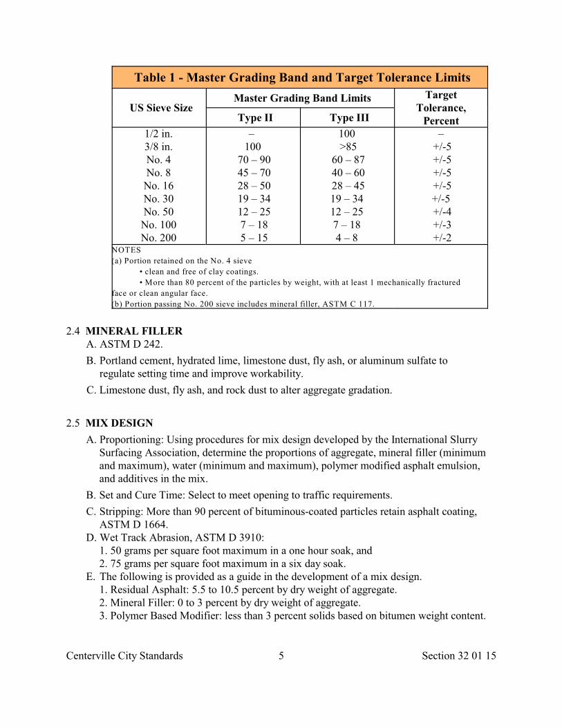
Centerville City Standards 5 Section 32 01 15
Table 1 - Master Grading Band and Target Tolerance Limits
US Sieve SizeMaster Grading Band Limits Target
Tolerance,PercentType II Type III
1/2 in.3/8 in.No. 4No. 8No. 16No. 30No. 50No. 100No. 200
– 100
70 – 90 45 – 70 28 – 50 19 – 34 12 – 25 7 – 18 5 – 15
100 >85
60 – 87 40 – 60 28 – 4519 – 34 12 – 25 7 – 18 4 – 8
– +/-5 +/-5 +/-5 +/-5+/-5 +/-4 +/-3 +/-2
NOTES
(a) Portion retained on the No. 4 sieve
• clean and free of clay coatings.
• More than 80 percent of the particles by weight, with at least 1 mechanically fractured
face or clean angular face.
(b) Portion passing No. 200 sieve includes mineral filler, ASTM C 117.
2.4 MINERAL FILLER A. ASTM D 242.
B. Portland cement, hydrated lime, limestone dust, fly ash, or aluminum sulfate toregulate setting time and improve workability.
C. Limestone dust, fly ash, and rock dust to alter aggregate gradation.
2.5 MIX DESIGN
A. Proportioning: Using procedures for mix design developed by the International SlurrySurfacing Association, determine the proportions of aggregate, mineral filler (minimumand maximum), water (minimum and maximum), polymer modified asphalt emulsion,and additives in the mix.
B. Set and Cure Time: Select to meet opening to traffic requirements.
C. Stripping: More than 90 percent of bituminous-coated particles retain asphalt coating,ASTM D 1664.
D. Wet Track Abrasion, ASTM D 3910: 1. 50 grams per square foot maximum in a one hour soak, and 2. 75 grams per square foot maximum in a six day soak.
E. The following is provided as a guide in the development of a mix design. 1. Residual Asphalt: 5.5 to 10.5 percent by dry weight of aggregate. 2. Mineral Filler: 0 to 3 percent by dry weight of aggregate. 3. Polymer Based Modifier: less than 3 percent solids based on bitumen weight content.
Centerville City Standards 6 Section 32 01 15
4. Clay Content: Sand equivalent, ASTM D 2419: 65 minimum prior to adding additives. Note: Sand equivalency controls set time.
PART 3 EXECUTION
3.1 CONSTRUCTION EQUIPMENT
A. Mixing Equipment: The unit is to be a storage and mixing device capable of accuratelyproportioning and delivering aggregate, emulsified asphalt, mineral filler, additive, andwater on a continuous flow basis to a spreader box at a placement rate of at least 15,000square yards per day. Its proportioning devices are to be based upon either volume orweight control. Its mixer is to be a multi-blade, multi-shaft unit.
1. For lay downs longer than 600 feet, autonomous mixing equipment is required. 2. For lay downs less than 600 feet, truck mounted mixing equipment is permitted.
B. Spreader: The spreader is to have a front seal so no loss of the mixture occurs at roadcontact and an adjustable rear seal to act as a final strike-off device. The spreader is tohave a secondary strike off device to improve surface texture.
C. Rut Filling Box: Wide enough to bridge ruts.
3.2 PREPARATION A. General:
1. Fat or bleeding Pavements may require two scratch course applications. 2. Cracked or porous Pavements may require thin, SSI slurry surface treatment per
Section 32 01 13. 3. Asphalt concrete inlay may be required in rut deformations.
B. Protection: 1. Protect trees, plants and other ground cover from damage. 2. Prune trees per Section 32 01 93 to allow equipment passage underneath. Repair tree
damage. 3. Install invert covers. 4. Mask Street Fixtures. 5. Protect curb, gutter, and sidewalk from spatter, mar, or overcoat.
C. Traffic Control: 1. Control pedestrian and vehicular traffic, Section 01 55 26. 2. Protect micro surface seal from traffic until seal has cured. Length of time depends on
type of asphalt, mixture characteristics and weather. 3. Do not proceed without flaggers. 4. Do not apply lane marking tape or paint until layout has been verified with
City Engineer. D. Surface Repair: Patch any holes, raveled areas, and low areas with asphalt concrete. E. Cleaning:
1. Remove mud spots, sand, dust, oil, vegetation and other objectionable material. 2. Remove loose material that may cause drag marks.
Centerville City Standards 7 Section 32 01 15
3. Do not water flush cracked Pavements. F. Crack Repair: Section 32 01 17.
1. Remove plant materials from cracks, edges and joints. 2. Blow cracks clean. 3. Seal cracks with crack pouring asphalt. Remove excess asphalt. 4. Allow crack seal to dry before surfacing.
G. Tack Coat: 1. Apply tack coat to high-absorbent, polished, oxidized, or raveled asphalt surfaces or to
concrete or brick surfaces. Use the same asphalt emulsion as used in the micro- surfacing seal.
2. Apply tack coat and pave over concrete Cover Collars. H. Existing Roadway Striping: Use reflective tabs to mark roadway striping before applying micro-surface seal.
3.3 SPOT LEVELING A. Where rut deformation is less than 1/2 inch apply only amount of micro-surfacing needed to level the surface (scratch course). B. Where rut deformation exceeds 1/2 inch:
1. Mill high spots. 2. Use a rut-filling box. 3. Use multiple placements when ruts exceed 1-1/2 inches. For every inch of micro
surfacing add 1/8th to 1/4 of an inch of material as a crown (allows for compaction under traffic).
4. Allow 3 days cure time under traffic. C. Where asphalt concrete pushing or shoving has occurred, provide asphalt concrete inlay as follows.
1. Mill damaged area at least 3 inches below elevation required for leveling. 2. Install and compact 3 inches of AC-20-DM-3/4 asphalt concrete, Section 32 12 17.
3.4 APPLICATION
A. General:
1. After spot leveling, the average application rates are to fall within the followingranges.
a. Type II Aggregate: 16 to 18 pounds per square yard. b. Type III Aggregate: 20 to 25 pounds per square yard.
2. Machine meter settings must match mix design. Water and mineral filler may be changed per mix design; otherwise, a new mix design is required.
3. Pre-wet existing pavements surface to prevent premature breaking or to improve bonding.
4. Wait at least 2 hours if an adjacent pass has broken and started to cure. B. Mineral Filler: During application, mineral filler (per mix design) may be increased or
decreased for better consistency or set time.
C. In the spreader box.
Centerville City Standards 8 Section 32 01 15
1. No spreading of material remaining in box when mixer is shut off. 2. No additional water added to the box. 3. No lumping, balling or unmixed aggregate. 4. No segregation of the emulsion and aggregate fines from the coarse aggregate. 5. No breaking of emulsion. 6. No overloading. Carry a sufficient amount of slurry in all parts of the spreader for
complete coverage. D. Joints:
1. Make transverse joints straight-cut butt type, not over-lap type. 2. Place longitudinal joints on lane lines. Limit overlap to 3 inches maximum. 3. Tolerance for joint match is 1/4 inch difference in elevation when measured with a 10
feet long straight edge over the joint. 4. Stop and correct paving operation if longitudinal or transverse joints have uncovered
areas or unsightly appearance. E. Lines:
1. Make straight lines along lip of gutter and shoulders. No runoff on these areas will be permitted.
2. Mask off the end of streets and intersections to provide straight lines. 3. Vary edge lines no more than 2 inches per 100 feet.
3.5 AFTER APPLICATION
A. Leave no streaks caused by oversized aggregate particles or buildup of slurry mix onsqueegees.
B. Leave no holes, bare spots, or cracks through which liquids or foreign matter couldpenetrate to the underlying Pavement.
C. If coarse aggregate settles to the bottom of the mix, remove and replace the application.
D. Expose Manholes, valve boxes, inlets and other service entrances clean after application.
E. Do not permit traffic on micro-surface until surface has cured.
F. Do not apply lane marking tape or paint until layout and placement has been verified withCity Engineer.
3.6 FIELD QUALITY CONTROL
A. If ASTM C 136 shows aggregate gradation non-compliance, either remove thematerial or blend in other aggregates to bring it into compliance. This may require anew mix design. Screening may be required at the stockpile to remove any oversizematerials.
3.7 REPAIR
A. Fill any joints or cracks that are not filled by product.
Centerville City Standards 9 Section 32 01 15
B. Remove overcoat.
C. Remove micro-surfacing seal from Street Fixtures.
D. Make correction lines straight.
E. Repair collateral damage caused by construction.
END OF SECTION
Centerville City Standards 1 Section 32 01 17
SECTION 32 01 17
PAVEMENT CRACK SEAL
PART 1 GENERAL
1.1 SECTION INCLUDES A. Filling and sealing cracks in asphalt concrete Pavements.
1.2 REFERENCES
A. ASTM D 36: Standard Test Method for Softening Point of Bitumen (Ring-and BallApparatus)
B. ASTM D 977: Standard Specification for Emulsified Asphalt.
C. ASTM D 1190: Standard Specification for Concrete Joint Sealer, Hot-Poured ElasticType.
D. ASTM D 2397: Standard Specification for Cationic Emulsifed Asphalt.
E. ASTM D 3381: Standard Specification for Viscosity-Graded Asphalt Cement for Usein Pavement Construction.
F. ASTM D 3405: Standard Specification for Joint Sealants, Hot-Poured, For Concrete andAsphalt Pavements.
G. ASTM D 5078: Standard Specification for Crack Filler for Asphalt Concrete andPortland Cement Concrete Pavements.
H. ASTM D 5329: Standard Test Methods for Sealants and Fillers, Hot-Applied for Jointsand Cracks in Asphaltic and Portland Cement Concrete Pavements.
1.3 DEFINITIONS
A. Crack Filling: The placement of materials into cracks to substantially reduce infiltrationof water and to reinforce the adjacent Pavement. The crack receives no specialpreparation other than cleaning.
B. Crack Sealing: The placement of specialized materials in cracks or above to preventthe intrusion of incompressibles and water into the crack. The crack receives uniquecrack configuration prepartion.
C. Pothole: Loss of surface material in a Pavement to the extent that a patch is necessaryto restore Pavement ride quality.
1.4 SUBMITTALS
A. Product Data sheets.
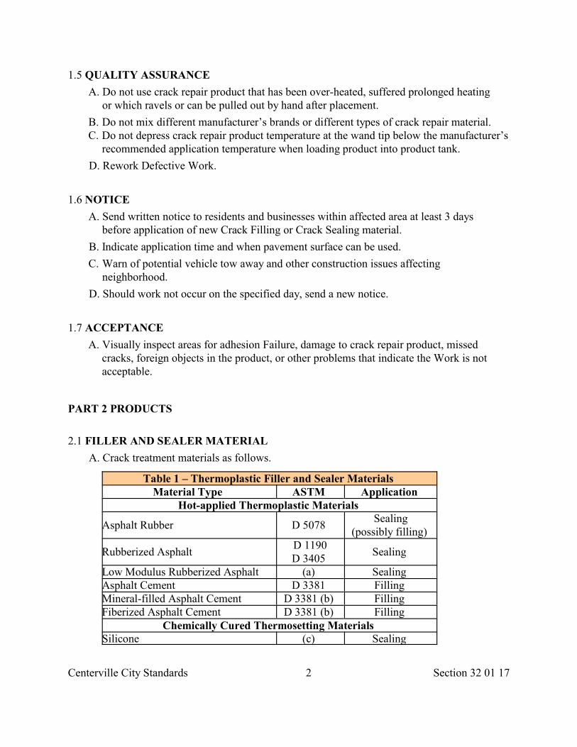
Centerville City Standards 2 Section 32 01 17
1.5 QUALITY ASSURANCE
A. Do not use crack repair product that has been over-heated, suffered prolonged heatingor which ravels or can be pulled out by hand after placement.
B. Do not mix different manufacturer’s brands or different types of crack repair material. C. Do not depress crack repair product temperature at the wand tip below the manufacturer’s
recommended application temperature when loading product into product tank.
D. Rework Defective Work.
1.6 NOTICE
A. Send written notice to residents and businesses within affected area at least 3 daysbefore application of new Crack Filling or Crack Sealing material.
B. Indicate application time and when pavement surface can be used.
C. Warn of potential vehicle tow away and other construction issues affectingneighborhood.
D. Should work not occur on the specified day, send a new notice.
1.7 ACCEPTANCE
A. Visually inspect areas for adhesion Failure, damage to crack repair product, missedcracks, foreign objects in the product, or other problems that indicate the Work is notacceptable.
PART 2 PRODUCTS
2.1 FILLER AND SEALER MATERIAL
A. Crack treatment materials as follows.
Table 1 – Thermoplastic Filler and Sealer Materials Material Type ASTM Application
Hot-applied Thermoplastic Materials
Asphalt Rubber D 5078 Sealing
(possibly filling)
Rubberized Asphalt D 1190D 3405
Sealing
Low Modulus Rubberized Asphalt (a) Sealing Asphalt Cement D 3381 Filling Mineral-filled Asphalt Cement D 3381 (b) Filling Fiberized Asphalt Cement D 3381 (b) Filling
Chemically Cured Thermosetting Materials Silicone (c) Sealing
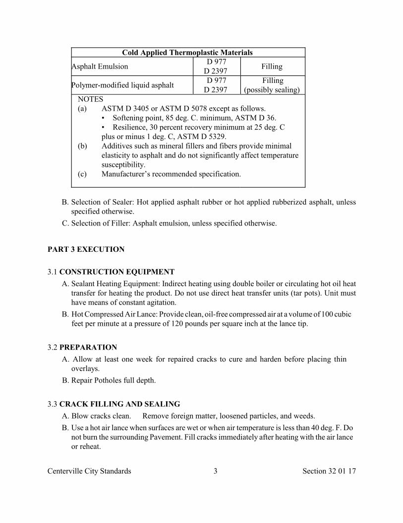
Centerville City Standards 3 Section 32 01 17
Cold Applied Thermoplastic Materials
Asphalt Emulsion D 977
D 2397 Filling
Polymer-modified liquid asphalt D 977
D 2397 Filling
(possibly sealing) NOTES (a) ASTM D 3405 or ASTM D 5078 except as follows.
• Softening point, 85 deg. C. minimum, ASTM D 36. • Resilience, 30 percent recovery minimum at 25 deg. C plus or minus 1 deg. C, ASTM D 5329.
(b) Additives such as mineral fillers and fibers provide minimal elasticity to asphalt and do not significantly affect temperature susceptibility.
(c) Manufacturer’s recommended specification.
B. Selection of Sealer: Hot applied asphalt rubber or hot applied rubberized asphalt, unlessspecified otherwise.
C. Selection of Filler: Asphalt emulsion, unless specified otherwise.
PART 3 EXECUTION
3.1 CONSTRUCTION EQUIPMENT
A. Sealant Heating Equipment: Indirect heating using double boiler or circulating hot oil heattransfer for heating the product. Do not use direct heat transfer units (tar pots). Unit musthave means of constant agitation.
B. Hot Compressed Air Lance: Provide clean, oil-free compressed air at a volume of 100 cubicfeet per minute at a pressure of 120 pounds per square inch at the lance tip.
3.2 PREPARATION
A. Allow at least one week for repaired cracks to cure and harden before placing thinoverlays.
B. Repair Potholes full depth.
3.3 CRACK FILLING AND SEALING
A. Blow cracks clean. Remove foreign matter, loosened particles, and weeds.
B. Use a hot air lance when surfaces are wet or when air temperature is less than 40 deg. F. Donot burn the surrounding Pavement. Fill cracks immediately after heating with the air lanceor reheat.
Centerville City Standards 4 Section 32 01 17
C. Fill each crack to within 1/4 inch of the existing surface.
D. If a thin Pavement (chip seal, slurry seal, micro-surface) is to be applied, remove crackoverfill by squeegee.
3.4 PROTECTION
A. Place sand on surface of crack repair product if traffic or construction activities are likelyto cause pull out. Replace pulled out product.
B. Repair vehicles or other property damaged by crack repair operation.
END OF SECTION
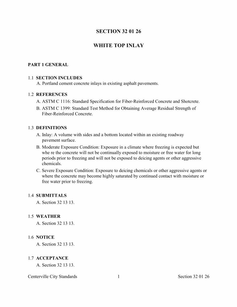
Centerville City Standards 1 Section 32 01 26
SECTION 32 01 26
WHITE TOP INLAY
PART 1 GENERAL
1.1 SECTION INCLUDES A. Portland cement concrete inlays in existing asphalt pavements.
1.2 REFERENCES
A. ASTM C 1116: Standard Specification for Fiber-Reinforced Concrete and Shotcrete.
B. ASTM C 1399: Standard Test Method for Obtaining Average Residual Strength ofFiber-Reinforced Concrete.
1.3 DEFINITIONS
A. Inlay: A volume with sides and a bottom located within an existing roadwaypavement surface.
B. Moderate Exposure Condition: Exposure in a climate where freezing is expected butwhe re the concrete will not be continually exposed to moisture or free water for longperiods prior to freezing and will not be exposed to deicing agents or other aggressivechemicals.
C. Severe Exposure Condition: Exposure to deicing chemicals or other aggressive agents orwhere the concrete may become highly saturated by continued contact with moisture orfree water prior to freezing.
1.4 SUBMITTALS
A. Section 32 13 13.
1.5 WEATHER
A. Section 32 13 13.
1.6 NOTICE
A. Section 32 13 13.
1.7 ACCEPTANCE
A. Section 32 13 13.
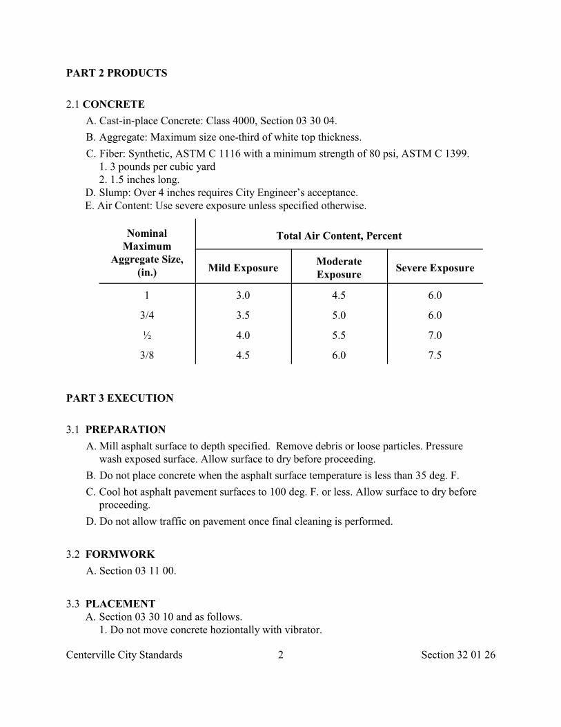
Centerville City Standards 2 Section 32 01 26
PART 2 PRODUCTS
2.1 CONCRETE
A. Cast-in-place Concrete: Class 4000, Section 03 30 04.
B. Aggregate: Maximum size one-third of white top thickness.
C. Fiber: Synthetic, ASTM C 1116 with a minimum strength of 80 psi, ASTM C 1399. 1. 3 pounds per cubic yard 2. 1.5 inches long.
D. Slump: Over 4 inches requires City Engineer’s acceptance. E. Air Content: Use severe exposure unless specified otherwise.
NominalMaximum
Aggregate Size,(in.)
Total Air Content, Percent
Mild ExposureModerateExposure
Severe Exposure
1
3/4
½
3/8
3.0
3.5
4.0
4.5
4.5
5.0
5.5
6.0
6.0
6.0
7.0
7.5
PART 3 EXECUTION
3.1 PREPARATION
A. Mill asphalt surface to depth specified. Remove debris or loose particles. Pressurewash exposed surface. Allow surface to dry before proceeding.
B. Do not place concrete when the asphalt surface temperature is less than 35 deg. F.
C. Cool hot asphalt pavement surfaces to 100 deg. F. or less. Allow surface to dry beforeproceeding.
D. Do not allow traffic on pavement once final cleaning is performed.
3.2 FORMWORK
A. Section 03 11 00.
3.3 PLACEMENT A. Section 03 30 10 and as follows.
1. Do not move concrete hoziontally with vibrator.
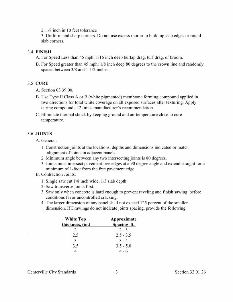
Centerville City Standards 3 Section 32 01 26
2. 1/8 inch in 10 feet tolerance 3. Uniform and sharp corners. Do not use excess mortar to build up slab edges or round
slab corners.
3.4 FINISH A. For Speed Less than 45 mph: 1/16 inch deep burlap drag, turf drag, or broom.
B. For Speed greater than 45 mph: 1/8 inch deep 80 degrees to the crown line and randomlyspaced between 3/8 and 1-1/2 inches.
3.5 CURE
A. Section 03 39 00.
B. Use Type II Class A or B (white pigmented) membrane forming compound applied intwo directions for total white coverage on all exposed surfaces after texturing. Applycuring compound at 2 times manufacturer’s recommendation.
C. Eliminate thermal shock by keeping ground and air temperature close to curetemperature.
3.6 JOINTS
A. General:
1. Construction joints at the locations, depths and dimensions indicated or match alignment of joints in adjacent panels.
2. Minimum angle between any two intersecting joints is 80 degrees. 3. Joints must intersect pavement free edges at a 90 degree angle and extend straight for a
minimum of 1-foot from the free pavement edge. B. Contraction Joints:
1. Single saw cut 1/8 inch wide, 1/3 slab depth. 2. Saw transverse joints first. 3. Saw only when concrete is hard enough to prevent raveling and finish sawing before
conditions favor uncontrolled cracking. 4. The larger dimension of any panel shall not exceed 125 percent of the smaller
dimension. If Drawings do not indicate joints spacing, provide the following.
White Top Approximate thickness, (in.) Spacing ft.
2 2 - 32.5 2.5 - 3.53 3 - 4
3.5 3.5 - 5.04 4 - 6
Centerville City Standards 4 Section 32 01 26
C. Isolation Joints: 1/2 inch thick sheet filler type F1, Section 32 13 73. Use this joint wherepavement abuts building, manholes and other fixed objects.
D. Joint Sealing: Not required.
3.7 PROTECTION AND REPAIRS
A. Protection: Immediately after placement, protect concrete from graffiti or other types ofmechanical injury.
B. Repair:
1. Remove and replace cracked panels. 2. Patch spall with Section 03 61 00 shrinkage resistant grout. 3. Remove graffiti.
3.8 OPENING TO TRAFFIC
A. Not sooner than 3,000 psi.
END OF SECTION
Centerville City Standards 1 Section 32 01 29
SECTION 32 01 29
CONCRETE PAVING RAISING
PART 1 GENERAL
1.1 SECTION INCLUDES A. Raising settled concrete flat work to grade.
1.2 REFERENCES A. ASTM C 150: Standard Specification for Portland cement.
1.3 SUBMITTALS A. Plan for containing mud in the jacking process. B. Data sheet for shrinkage resistant grout.
PART 2 PRODUCTS
2.1 MATERIALS A. Grout Mix: Shrinkage resistant, Section 03 61 00. B. Concrete Patch:
1. Portland cement, Type I or II ASTM C 150. 2. Silica sand. 3. Shrinkage compensating agent with plasticizing and water reducing agents.
PART 3 EXECUTION
3.1 JACKING
A. Raise slabs to be level with existing surfaces.
B. Contain mud during the jacking process. If containment is lost, implementremediation procedures immediately. Do not permit displacement of adjacentsurfaces.
C. Raising adjacent slabs or structures not scheduled for raising is considereddamage.
D. Repair or restore damaged item.
3.2 CLEANING
A. Do not permit rain or sprinkler system water to wash away dust.
END OF SECTION
Centerville City Standards 1 Section 32 01 90
SECTION 32 01 90
PLANT MAINTENANCE
PART 1 GENERAL
1.1 SECTION INCLUDES A. Landscape maintenance and replacement. B. Guarantees.
1.2 GRASS MAINTENANCE
A. General: Maintain surfaces until Work is accepted, but in any event for a period of notless than 60 days after planting. Supply additional topsoil where necessary, includingareas affected by erosion or settlement.
B. Watering: Water to ensure uniform seed germination and to keep surface of soil damp.Apply water slowly so soil will not puddle and crust.
C. Fertilizing: Fertilize during seeding and 2 weeks after seeding and sodding.
D. Mowing: Cut grass first time when it reaches a height of 2-1/2 inches and maintain tominimum height of 2 inches. Do not cut more than 1/3 of blade at any one mowing.Remove clippings. After first mowing, water to moisten soil from 3 inches to 5 inchesdeep. Allow a minimum of 5 days between mowings.
E. Grading: Roll when required to remove minor depressions orirregularities.
F. Control Growth of Weed: When using herbicides, apply in accordance withmanufacturer's recommendations. Remedy damage from improper use.
G. Protection: Protect planted areas with warning signs during maintenance period. Erectwhen necessary, temporary fences, or barriers, to control pedestrians.
1.3 TREES, PLANTS, AND GROUND COVER MAINTENANCE
A. General: Care for planted areas. Maintain, water, weed, repair, and protect until Work isaccepted, but in any event for a period of not less than 60 days after planting. Supplyadditional topsoil where necessary, including areas affected by erosion or settlement.
B. Watering: After planting, keep ground continuously moist until healthy growth isestablished. Thereafter, thoroughly water once a day until Work is accepted. Preventerosion.
C. Weeding: Uproot and remove weeds completely. Do not allow growth and germinationof weed seeds. Fill in large holes caused by weeding with topsoil and rake smooth.
D. Protection: Protect planted areas against traffic by erecting barricades and warningsigns. Replant damaged planted areas.
Centerville City Standards 2 Section 32 01 90
E. Maintain wrappings, guys, turnbuckles, and stakes. Adjust turnbuckles to keep wirestight. Repair or replace accessories when required.
1.4 REPLACEMENTS
A. When any portion of surface becomes gullied or otherwise damaged and planting hasfailed to grow, repair and replant.
B. At conclusion of maintenance period, replant areas showing root growth Failure, bare orthin spots, and eroded or settled areas with materials of like kind and size as specifiedfor original planting.
C. Throughout the maintenance period, replace any unsatisfactory or dead plants within 10days of written notice.
1.5 ACCEPTANCE
A. Seeded areas will be accepted at end of maintenance period when seeded areas areestablished and have been mowed at least 3 times.
B. All other areas will be accepted not less than 60 days after planting and successfulgrowth.
1.6 GUARANTEE
A. Guarantee covers plant material establishment 1 year from date of acceptance.
B. Replace plant materials found dead or not in a healthy growing conditions with plantmaterials of same size and species with a new guarantee commencing on date ofreplacement.
C. At end of guarantee period if landscaped surfaces have settled causing poor drainageconditions, correct grade deficiencies. Make corrections after receiving approval ofcorrective methods and schedules.
D. Perform corrective work.
PART 2 PRODUCTS Not Used
PART 3 EXECUTION Not Used
END OF SECTION
Centerville City Standards 1 Section 32 01 91
SECTION 32 01 91
TREE ROOT CUTTING
PART 1 GENERAL
1.1 SECTION INCLUDES A. Cutting and removing tree roots. B. Protecting surface improvements from future tree root growth.
1.2 REFERENCES A. International Society of Arboriculture. (ISA).
1.3 PROJECT CONDITIONS
A. Provide written watering instructions to neighbors in property abutting the tree root cuts toadvise them of the tree's watering requirements.
1.4 QUALITY ASSURANCE
A. Provide an ISA certified arborist to observe tree root cutting. Upon City Engineer’srequest, provide a copy of the arborist's ISA certificate and registration number on filewith the State Division of Commercial Code.
PART 2 PRODUCTS Not Used
PART 3 EXECUTION
3.1 AVOIDING ROOT CUTS
A. When placing or replacing concrete sidewalk;
1. Adjust alignment to curve around, over or away from tree trunks. Do not proceed in this work until alignment has been reviewed by City Engineer.
2. Adjust thickness and concrete contraction score marks. B. When replacing concrete curb and gutter.
1. Adjust thickness and concrete contraction score marks over tree roots. 2. Do not vary gutter invert from straight grade.
3.2 CUTTING TREE ROOTS
A. Never cut buttress roots [i.e. roots at the broadened base of the tree trunk] withoutwritten authorization of arborist. Avoid injury to trunk.
Centerville City Standards 2 Section 32 01 91
B. Keep root cutting at least 4 feet away from tree trunk. Limit cutting to one side of tree unless authorized otherwise in writing by arborist.
C. Cut roots clean and straight (no ragged or torn edges). Use an axe, saw, or appropriateequipment that properly cuts roots. Do not make partial root cuts.
D. Do not injure roots to remain.
E. Cut roots back to root laterals.
3.3 BACKFILLING
A. Backfill all cut and exposed roots the same day of root cutting, or cover with woodchips, mulch and water until backfilling is accomplished.
B. Place soil below root cut.
C. To prevent vertical root growth, place an impermeable membrane over root cuts. Bendmembrane edges to plane below cut root. Place backfill materials adjacent to and aboveimpermeable membrane.
3.4 PROTECTION
A. After cutting roots of tree.
1. Immediately water tree after backfilling. 2. Apply a minimum of 1 inch of water over the entire area under the tree canopy
and well beyond over a period of 4 hours. 3. Restrict water runoff.
END OF SECTION
Centerville City Standards 1 Section 32 01 93
SECTION 32 01 93
PRUNING TREES
PART 1 GENERAL
1.1 SECTION INCLUDES A. Pruning branches of existing trees.
1.2 REFERENCES
A. ANSI A 300: Tree Care Operation-Tree, Shrub, and Other Woody Plants.
B. ANSI Z 133.1: Pruning, Trimming, Repairing, Maintaining, and Removing Trees,and Cutting Brush-Safety Requirements.
C. International Society of Arboriculture. (ISA) -Current Standards for Pruning.
D. Utah Community Forest Council: Utah Shade Tree Pruning Standards
1.3 SUBMITTALS
A. Tree protection plan that identifies trees to be pruned and reasons for pruning.
B. Upon City Engineer’s request, submit a copy of the arborist’s certificate from ISA andregistration number on file with the State Division of Commercial Code.
1.4 QUALITY ASSURANCE
A. Provide an ISA certified arborist to observe tree pruning. Upon City Engineer’s request,provide a copy of the arborist's ISA certificate and registration number on file with theState Division of Commercial Code.
PART 2 PRODUCTS
2.1 PRUNING PAINT
A. Formulated for horticultural application to cut or damaged plant tissue.
2.2 DISINFECTANT
A. Chlorine based.
PART 3 EXECUTION
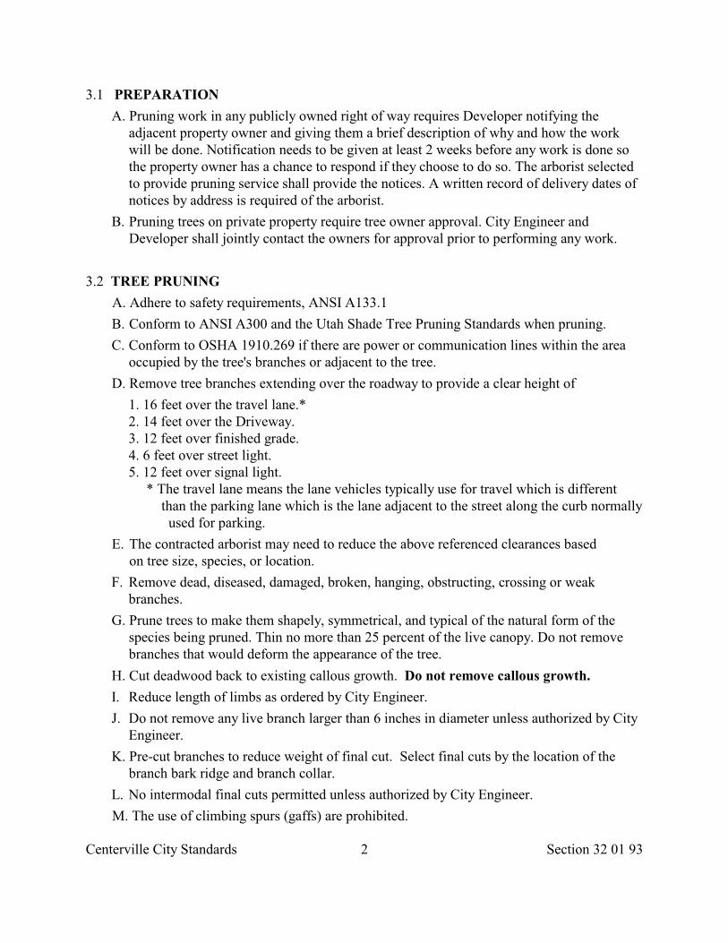
Centerville City Standards 2 Section 32 01 93
3.1 PREPARATION
A. Pruning work in any publicly owned right of way requires Developer notifying theadjacent property owner and giving them a brief description of why and how the workwill be done. Notification needs to be given at least 2 weeks before any work is done sothe property owner has a chance to respond if they choose to do so. The arborist selectedto provide pruning service shall provide the notices. A written record of delivery dates ofnotices by address is required of the arborist.
B. Pruning trees on private property require tree owner approval. City Engineer andDeveloper shall jointly contact the owners for approval prior to performing any work.
3.2 TREE PRUNING
A. Adhere to safety requirements, ANSI A133.1
B. Conform to ANSI A300 and the Utah Shade Tree Pruning Standards when pruning.
C. Conform to OSHA 1910.269 if there are power or communication lines within the areaoccupied by the tree's branches or adjacent to the tree.
D. Remove tree branches extending over the roadway to provide a clear height of
1. 16 feet over the travel lane.* 2. 14 feet over the Driveway. 3. 12 feet over finished grade. 4. 6 feet over street light. 5. 12 feet over signal light.
* The travel lane means the lane vehicles typically use for travel which is differentthan the parking lane which is the lane adjacent to the street along the curb normally used for parking.
E. The contracted arborist may need to reduce the above referenced clearances basedon tree size, species, or location.
F. Remove dead, diseased, damaged, broken, hanging, obstructing, crossing or weakbranches.
G. Prune trees to make them shapely, symmetrical, and typical of the natural form of thespecies being pruned. Thin no more than 25 percent of the live canopy. Do not removebranches that would deform the appearance of the tree.
H. Cut deadwood back to existing callous growth. Do not remove callous growth.
I. Reduce length of limbs as ordered by City Engineer.
J. Do not remove any live branch larger than 6 inches in diameter unless authorized by CityEngineer.
K. Pre-cut branches to reduce weight of final cut. Select final cuts by the location of thebranch bark ridge and branch collar.
L. No intermodal final cuts permitted unless authorized by City Engineer.
M. The use of climbing spurs (gaffs) are prohibited.
Centerville City Standards 3 Section 32 01 93
N. Disinfect pruning equipment that comes in contact with diseased plant material. Removedisinfectant from equipment prior to proceeding with work.
O. Use the "Natural Target" or "Drop Crotch" pruning method when removing limbs.
P. Do not top, pollard, stub or dehorn any tree.
Q. Make all pruning cuts sufficiently close to the trunk or parent limbs without cutting intoor removing the "branch collar" or the "branch bark ridge".
3.3 BRANCH DISPOSAL
A. Remove branches from site.
B. Remove all wood chips.
END OF SECTION
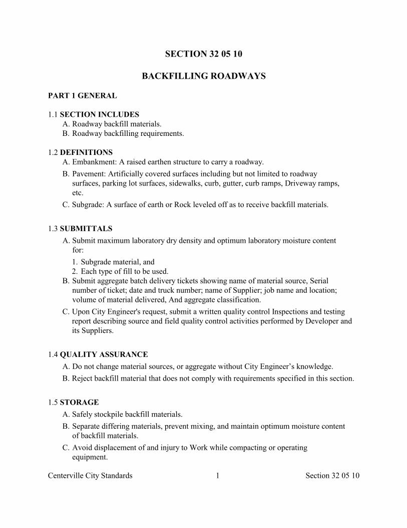
Centerville City Standards 1 Section 32 05 10
SECTION 32 05 10
BACKFILLING ROADWAYS
PART 1 GENERAL
1.1 SECTION INCLUDES A. Roadway backfill materials. B. Roadway backfilling requirements.
1.2 DEFINITIONS A. Embankment: A raised earthen structure to carry a roadway.
B. Pavement: Artificially covered surfaces including but not limited to roadwaysurfaces, parking lot surfaces, sidewalks, curb, gutter, curb ramps, Driveway ramps,etc.
C. Subgrade: A surface of earth or Rock leveled off as to receive backfill materials.
1.3 SUBMITTALS
A. Submit maximum laboratory dry density and optimum laboratory moisture contentfor:
1. Subgrade material, and 2. Each type of fill to be used.
B. Submit aggregate batch delivery tickets showing name of material source, Serialnumber of ticket; date and truck number; name of Supplier; job name and location;volume of material delivered, And aggregate classification.
C. Upon City Engineer's request, submit a written quality control Inspections and testingreport describing source and field quality control activities performed by Developer andits Suppliers.
1.4 QUALITY ASSURANCE
A. Do not change material sources, or aggregate without City Engineer’s knowledge.
B. Reject backfill material that does not comply with requirements specified in this section.
1.5 STORAGE
A. Safely stockpile backfill materials.
B. Separate differing materials, prevent mixing, and maintain optimum moisture contentof backfill materials.
C. Avoid displacement of and injury to Work while compacting or operatingequipment.
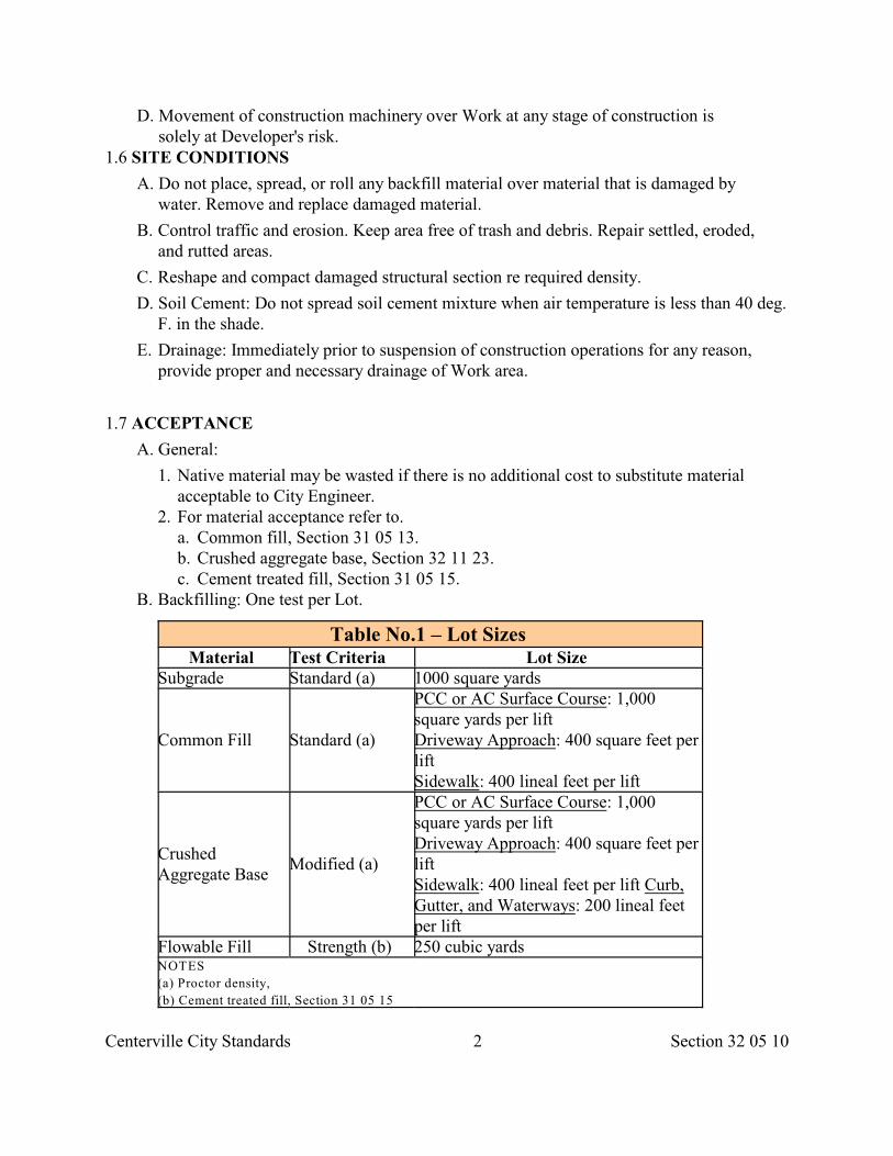
Centerville City Standards 2 Section 32 05 10
D. Movement of construction machinery over Work at any stage of construction issolely at Developer's risk.
1.6 SITE CONDITIONS
A. Do not place, spread, or roll any backfill material over material that is damaged bywater. Remove and replace damaged material.
B. Control traffic and erosion. Keep area free of trash and debris. Repair settled, eroded,and rutted areas.
C. Reshape and compact damaged structural section re required density.
D. Soil Cement: Do not spread soil cement mixture when air temperature is less than 40 deg.F. in the shade.
E. Drainage: Immediately prior to suspension of construction operations for any reason,provide proper and necessary drainage of Work area.
1.7 ACCEPTANCE
A. General:
1. Native material may be wasted if there is no additional cost to substitute materialacceptable to City Engineer.
2. For material acceptance refer to. a. Common fill, Section 31 05 13. b. Crushed aggregate base, Section 32 11 23. c. Cement treated fill, Section 31 05 15.
B. Backfilling: One test per Lot.
Table No.1 – Lot Sizes Material Test Criteria Lot Size
Subgrade Standard (a) 1000 square yards
Common Fill Standard (a)
PCC or AC Surface Course: 1,000square yards per lift Driveway Approach: 400 square feet perliftSidewalk: 400 lineal feet per lift
CrushedAggregate Base
Modified (a)
PCC or AC Surface Course: 1,000square yards per liftDriveway Approach: 400 square feet perliftSidewalk: 400 lineal feet per lift Curb,Gutter, and Waterways: 200 lineal feetper lift
Flowable Fill Strength (b) 250 cubic yards NOTES
(a) Proctor density,
(b) Cement treated fill, Section 31 05 15
Centerville City Standards 3 Section 32 05 10
(c) Lift thickness before compaction, 8 inches.
1.8 WARRANTY
A. Any settlement noted in Embankment or Pavement construction will be considered to becaused by improper compaction methods and shall be.
B. Restore incidentals damaged by settlement.
PART 2 PRODUCTS
2.1 BACKFILL MATERIALS
A. Common Fill, Section 31 05 13.
B. Crushed aggregate base, Section 32 11 23.
C. Cement treated fill, Section 31 05 15.
2.2 ACCESSORIES
A. Water:
1. Make arrangements for sources of water during construction and make arrangementsfor delivery of water to site.
2. Comply with local Laws and Regulations when securing water from water utilitycompany.
B. Geotextile Fabric, Section 31 05 19.
PART 3 EXECUTION
3.1 PREPARATION
A. Verify.
1. Backfill material meets gradation requirements. 2. Areas to be backfilled are free of debris, snow, ice or water, and 3. Bearing surfaces are not frozen.
B. If extra excavation is required, secure City Engineer’s written permission and followSection 31 23 16 requirements.
C. Place geotextile fabrics, Section 31 05 19.
3.2 SUBGRADE PREPARATION
A. Protect Subgrade from desiccation, flooding, and freezing.
B. If ground water table is in the intended construction operations, dewater.
Centerville City Standards 4 Section 32 05 10
C. Before beginning backfilling operations over Subgrade, secure City Engineer’sreview of Subgrade surface preparations.
3.3 EMBANKMENTS A. Place backfill material in lifts not exceeding 8 inches after compaction.
B. Build shoulders to a grade higher than that of adjacent fills. Provide surface runoff atall times.
C. Commence compaction along edge of area to be compacted and graduallyadvance toward center.
D. Operate compaction equipment along lines parallel or concentric with the center-lineof the Embankment being constructed.
E. Do not damage subsurface structures or utilities.
3.4 BASE COURSES
A. Place backfill material in lifts not exceeding 8 inches before compaction.
B. Maintain moisture content in compaction operations.
C. Avoid segregation when spreading backfill. Keep surfaces free from pockets of coarseand fine aggregate.
D. Rework fills which do not conform to compaction requirements until requirements aremet.
E. Protect cement treated fill against freezing and traffic for 7 days.
3.5 MODIFIED BACKFILL LAYER METHOD
A. Section 33 05 20.
3.6 COMPACTION A. Compact backfill, Section 33 05 05 as follows.
1. A-1 soils: greater than or equal to 95 percent of a Modified Proctor Density. 2. Other soils: greater than or equal to 95 percent of a Standard Proctor Density.
3.7 COMPRESSIVE STRENGTH
A. Where a flowable fill is used, provide compressive strength indicated in Section 31 0515.
3.8 PROOF ROLLING TEST
A. Prior to placing fill material for roadbed backfills, proof roll Subgrade using gross weightof 18,000 pounds/tandem axle, with a tire pressure at least 90 psi.
Centerville City Standards 5 Section 32 05 10
B. All proof roll passes will traverse the Subgrade parallel to the roadbed centerline. Allsubsequent passes will be offset 1/2 the vehicle width until the entire Subgrade istested.
C. City Engineer will analyze, determine, designate and measure the areas, if any, requiringadditional compaction or reconstruction.
D. Once Subgrade passes the proof rolling test, protect the surface from constructionoperations and traffic damage. Repair all cuts, ruts, and breaks. Keep surface in asatisfactory condition until geotextile fabric or base course has been placed.
3.9 CLEANING
A. Remove stockpiles from the site upon Work Completion. Grade site to prevent freestanding surface water.
B. Leave borrow areas clean and neat.
END OF SECTION
Centerville City Standards 1 Section 32 11 23
SECTION 32 11 23
CRUSHED AGGREGATE BASE
PART 1 GENERAL
1.1 SECTION INCLUDES A. Treated or untreated base course requirements.
1.2 REFERENCES A. ASTM C 29: Standard Test Method for Unit Weight and Voids in Aggregate.
B. ASTM C 131: Standard Test Method for Resistance to Degradation of Small-SizeCoarse Aggregate by Abrasion and Impact in the Los Angeles Machine.
C. ASTM C 136: Standard Method for Sieve Analysis of Fine and Coarse Aggregates.
D. ASTM D 75: Standard Practice for Sampling Aggregates.
E. ASTM D 448: Standard Classification for Sizes of Aggregate for Road and BridgeConstruction.
F. ASTM D 1883: Standard Test Method for CBR (California Bearing Ratio) ofLaboratory-Compacted Soils.
G. ASTM D 2419: Standard Test Method for Sand Equivalent Value of Soils and FineAggregate.
H. ASTM D 3665: Standard Practice for Random Sampling ofConstruction Materials.
I. ASTM D 3740: Standard Recommended Practice for Evaluation of Agencies Engagedin Testing and/or Inspection of Soil and Rock as Used in Engineering Design andConstruction.
J. ASTM D 4318: Standard Test Method for Liquid Limit, Plastic Limit, and PlasticityIndex of Soils.
K. ASTM D 5821: Standard Test Method for Determining the percentage of FracturedParticles in Coarse Aggregate.
1.3 DEFINITIONS
A. Aggregate Grading Band: Allowable deviation from Target Gradation Curve based uponthe number of gradation tests in a Lot. It is possible that gradation for any sieve may lieoutside of its respective Master Grading Band limits.
B. Master Grading Band: Gradation limits allowed for various sieve sizes ranging from themaximum size sieve to the No. 200 sieve.
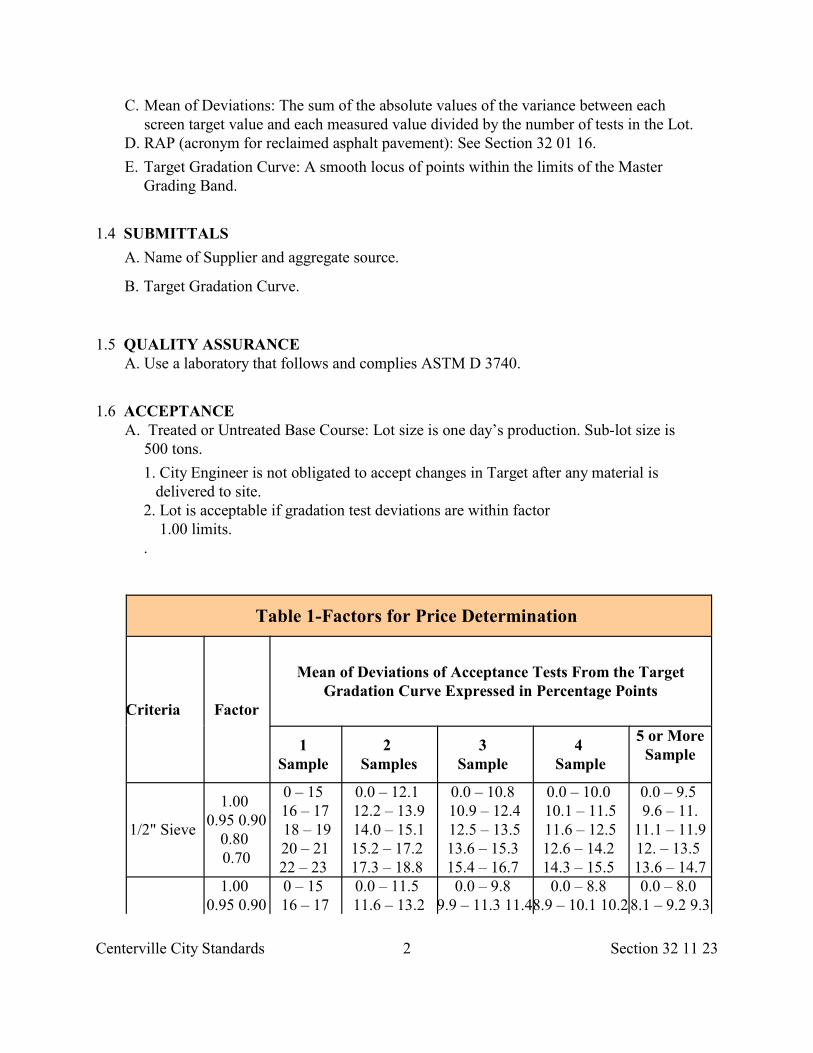
Centerville City Standards 2 Section 32 11 23
C. Mean of Deviations: The sum of the absolute values of the variance between eachscreen target value and each measured value divided by the number of tests in the Lot.
D. RAP (acronym for reclaimed asphalt pavement): See Section 32 01 16.
E. Target Gradation Curve: A smooth locus of points within the limits of the MasterGrading Band.
1.4 SUBMITTALS
A. Name of Supplier and aggregate source.
B. Target Gradation Curve.
1.5 QUALITY ASSURANCE A. Use a laboratory that follows and complies ASTM D 3740.
1.6 ACCEPTANCE A. Treated or Untreated Base Course: Lot size is one day’s production. Sub-lot size is
500 tons.
1. City Engineer is not obligated to accept changes in Target after any material is delivered to site.
2. Lot is acceptable if gradation test deviations are within factor 1.00 limits. .
Table 1-Factors for Price Determination
Criteria Factor
Mean of Deviations of Acceptance Tests From the TargetGradation Curve Expressed in Percentage Points
1 Sample
2 Samples
3 Sample
4 Sample
5 or MoreSample
1/2" Sieve
1.00 0.95 0.90
0.80 0.70
0 – 15 16 – 17 18 – 19 20 – 21 22 – 23
0.0 – 12.1 12.2 – 13.914.0 – 15.115.2 – 17.2 17.3 – 18.8
0.0 – 10.8 10.9 – 12.412.5 – 13.513.6 – 15.3 15.4 – 16.7
0.0 – 10.0 10.1 – 11.511.6 – 12.512.6 – 14.2 14.3 – 15.5
0.0 – 9.5 9.6 – 11.
11.1 – 11.912. – 13.5 13.6 – 14.7
1.00 0.95 0.90
0 – 15 16 – 17
0.0 – 11.5 11.6 – 13.2
0.0 – 9.8 9.9 – 11.3 11.4
0.0 – 8.8 8.9 – 10.1 10.2
0.0 – 8.0 8.1 – 9.2 9.3
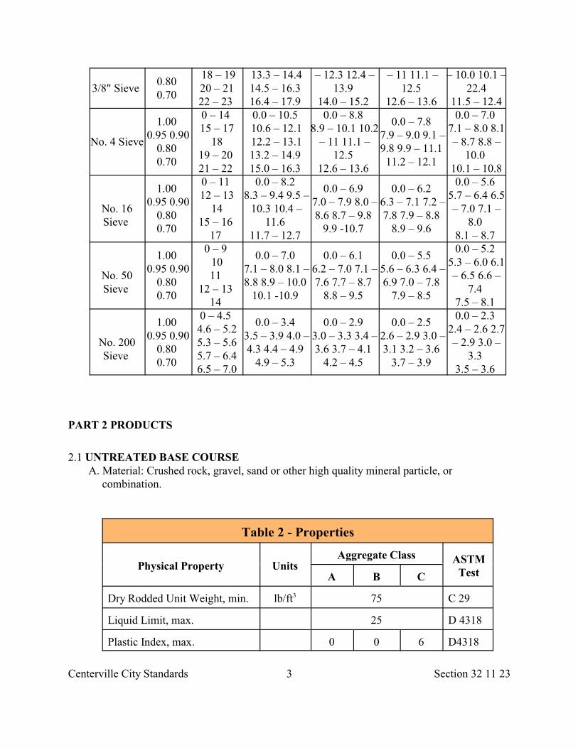
Centerville City Standards 3 Section 32 11 23
3/8" Sieve 0.80 0.70
18 – 19 20 – 21 22 – 23
13.3 – 14.414.5 – 16.3 16.4 – 17.9
– 12.3 12.4 –13.9
14.0 – 15.2
– 11 11.1 –12.5
12.6 – 13.6
– 10.0 10.1 –22.4
11.5 – 12.4
No. 4 Sieve
1.00 0.95 0.90
0.80 0.70
0 – 14 15 – 17
18 19 – 20 21 – 22
0.0 – 10.5 10.6 – 12.112.2 – 13.113.2 – 14.9 15.0 – 16.3
0.0 – 8.8 8.9 – 10.1 10.2
– 11 11.1 –12.5
12.6 – 13.6
0.0 – 7.8 7.9 – 9.0 9.1 –9.8 9.9 – 11.1 11.2 – 12.1
0.0 – 7.0 7.1 – 8.0 8.1– 8.7 8.8 –
10.0 10.1 – 10.8
No. 16Sieve
1.00 0.95 0.90
0.80 0.70
0 – 11 12 – 13
14 15 – 16
17
0.0 – 8.2 8.3 – 9.4 9.5 –
10.3 10.4 –11.6
11.7 – 12.7
0.0 – 6.9 7.0 – 7.9 8.0 –8.6 8.7 – 9.8
9.9 -10.7
0.0 – 6.2 6.3 – 7.1 7.2 –7.8 7.9 – 8.8
8.9 – 9.6
0.0 – 5.6 5.7 – 6.4 6.5– 7.0 7.1 –
8.0 8.1 – 8.7
No. 50Sieve
1.00 0.95 0.90
0.80 0.70
0 – 9 1011
12 – 13 14
0.0 – 7.0 7.1 – 8.0 8.1 –8.8 8.9 – 10.0
10.1 -10.9
0.0 – 6.1 6.2 – 7.0 7.1 –7.6 7.7 – 8.7
8.8 – 9.5
0.0 – 5.5 5.6 – 6.3 6.4 –6.9 7.0 – 7.8
7.9 – 8.5
0.0 – 5.2 5.3 – 6.0 6.1– 6.5 6.6 –
7.4 7.5 – 8.1
No. 200Sieve
1.00 0.95 0.90
0.80 0.70
0 – 4.5 4.6 – 5.25.3 – 5.65.7 – 6.46.5 – 7.0
0.0 – 3.4 3.5 – 3.9 4.0 –4.3 4.4 – 4.9
4.9 – 5.3
0.0 – 2.9 3.0 – 3.3 3.4 –3.6 3.7 – 4.1
4.2 – 4.5
0.0 – 2.5 2.6 – 2.9 3.0 –3.1 3.2 – 3.6
3.7 – 3.9
0.0 – 2.3 2.4 – 2.6 2.7– 2.9 3.0 –
3.3 3.5 – 3.6
PART 2 PRODUCTS
2.1 UNTREATED BASE COURSE A. Material: Crushed rock, gravel, sand or other high quality mineral particle, or
combination.
Table 2 - Properties
Physical Property UnitsAggregate Class ASTM
TestA B C
Dry Rodded Unit Weight, min. lb/ft 75 C 293
Liquid Limit, max. 25 D 4318
Plastic Index, max. 0 0 6 D4318
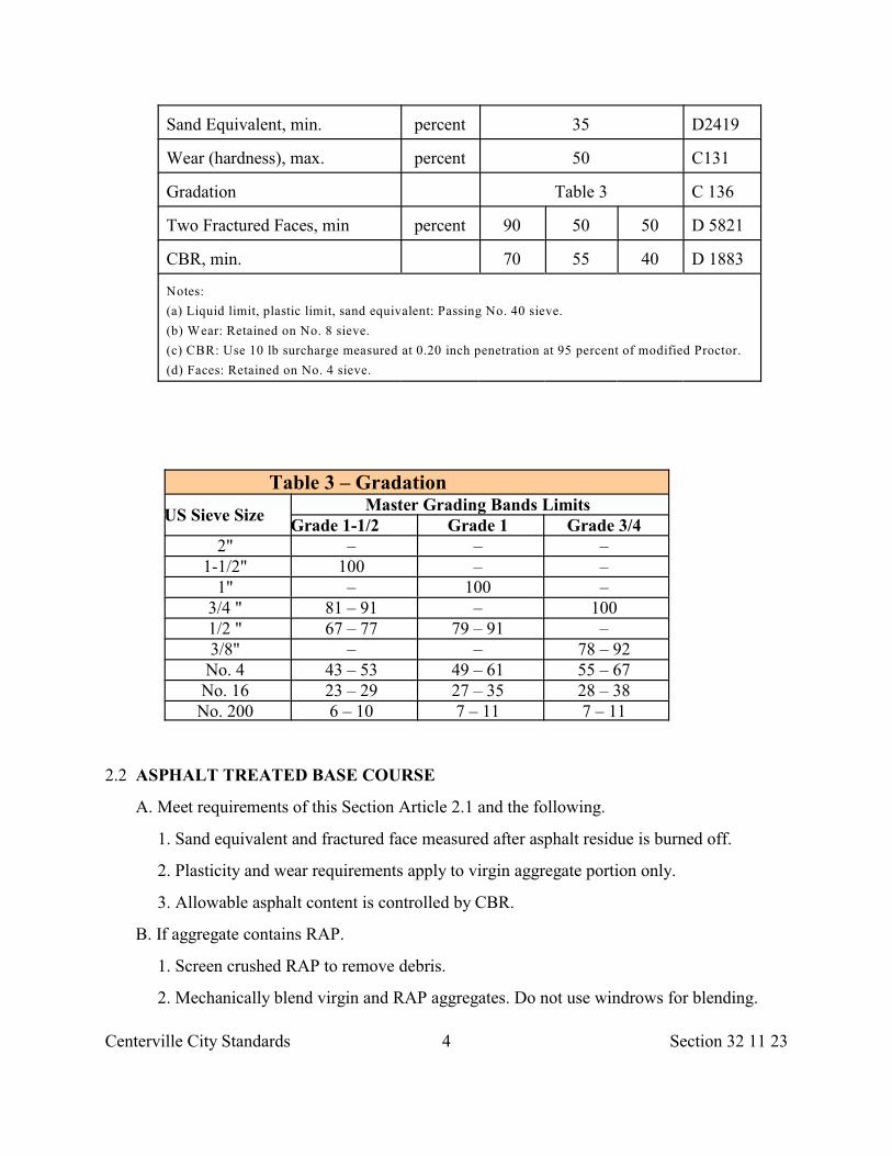
Centerville City Standards 4 Section 32 11 23
Sand Equivalent, min. percent 35 D2419
Wear (hardness), max. percent 50 C131
Gradation Table 3 C 136
Two Fractured Faces, min percent 90 50 50 D 5821
CBR, min. 70 55 40 D 1883
Notes:
(a) Liquid limit, plastic limit, sand equivalent: Passing No. 40 sieve.
(b) Wear: Retained on No. 8 sieve.
(c) CBR: Use 10 lb surcharge measured at 0.20 inch penetration at 95 percent of modified Proctor.
(d) Faces: Retained on No. 4 sieve.
Table 3 – Gradation
US Sieve Size Master Grading Bands Limits
Grade 1-1/2 Grade 1 Grade 3/4 2" – – –
1-1/2" 100 – – 1" – 100 –
3/4 " 81 – 91 – 100 1/2 " 67 – 77 79 – 91 – 3/8" – – 78 – 92
No. 4 43 – 53 49 – 61 55 – 67 No. 16 23 – 29 27 – 35 28 – 38 No. 200 6 – 10 7 – 11 7 – 11
2.2 ASPHALT TREATED BASE COURSE
A. Meet requirements of this Section Article 2.1 and the following.
1. Sand equivalent and fractured face measured after asphalt residue is burned off.
2. Plasticity and wear requirements apply to virgin aggregate portion only.
3. Allowable asphalt content is controlled by CBR.
B. If aggregate contains RAP.
1. Screen crushed RAP to remove debris.
2. Mechanically blend virgin and RAP aggregates. Do not use windrows for blending.
Centerville City Standards 5 Section 32 11 23
2.4 SOURCE QUALITY CONTROL
A. Sample, ASTM D 75 on a random basis, ASTM D 3665.
B. Reject crushed aggregate base products that do not meet requirements of this Section.
PART 3 EXECUTION
3.1 INSTALLATION
A. Trenches, Section 33 05 20.
B. Structures, Section 31 23 23.
C. Landscaping, Section 32 92 19.
D. Pavements, Section 32 05 10.
3.2 FIELD QUALITY CONTROL
A. Remove any product found defective after installation and install acceptable product.
END OF SECTION
Centerville City Standards 1 Section 32 12 03
SECTION 32 12 03
PAVING ASPHALTS
PART 1 GENERAL
1.1 SECTION INCLUDES
A. Performance graded asphalt, asphalt cement, cutback asphalt, emulsified asphalt, recycleasphalt, and crack patch asphalt.
B. Requirements for accepting non-complying paving asphalts.
1.2 REFERENCES
A. ASTM D 113: Standard Test Method for Ductility of Bituminous Materials.
B. ASTM D 977: Standard Specification for Emulsified Asphalt.
C. ASTM D 2026: Standard Specification for Cutback Asphalt (Slow-Curing Type).
D. ASTM D 2027: Standard Specification for Cutback Asphalt (Medium-Curing Type).
E. ASTM D 2028: Standard Specification for Cutback Asphalt (Rapid-Curing type).
F. ASTM D 2397: Standard Specification for Cationic Emulsified Asphalt.
G. ASTM D 3381: Standard Specification for Viscosity-Graded Asphalt Cement for Use inPavement Construction.
H. ASTM D 4552: Standard Practice for Classifying Hot-Mix Recycling Agents.
I. ASTM D 5710: Standard Specification for Trinidad Lake Modified Asphalt.
J. ASTM D 6373: Standard Specification for Performance Graded Asphalt Binder.
1.3 SUBMITTALS
A. Submit bill of lading for each shipment of paving asphalt from vendor. Identify thefollowing.
1. Source of product (manufacturer); 2. Type and grade of asphalt, And 3. Type and amount of additives in the product.
1.4 QUALITY ASSURANCE
A. Reject paving asphalts which are not uniform in appearance and consistency or whichfoam when heated to mixing temperature.
B. Do not use storage containers contaminated with other types or grades of Petroleum products.C. Do not use Petroleum product that does not comply with contract requirements.
Centerville City Standards 2 Section 32 12 03
1.5 ACCEPTANCE
A. General:
1. Acceptance is by Lot. One Lot is one day’s production. 2. If non-complying material has been installed and no price for the material is specified,
apply price adjustment against cost of work requiring material as part of itsinstallation. Section 01 29 00
3. Dispute resolution, Section 01 35 10. B. Performance Graded Asphalt Binder (PGAB): Sub-lot size is 20,000 gallons. Collect sub-
lot Sample randomly from oil storage unit.
1. Refer to limits identified in Section 209 of UDOT’s “Manual of Instruction Part 8Materials”. Pay factors are as follows.
a. If none of the critical properties are outside rejection limit a composite priceadjustment of 25 percent or less is allowed.
b. If one or more of the critical properties falls outside the rejection limit or if acomposite price adjustment is more than 25 percent, paving asphalt will be rejected.
C. Asphalt Cement (AC) Binder: Sub-lot size is 20,000 gallons. Collect sub-lot Samplerandomly from oil storage unit.
1. Ductility: Meet this Section’s requirements, or 2. Viscosity or Penetration: Meet graphics published in Section 955 of UDOT’s “Manual
of Instructions, Part 8 Materials”. a. Lot may be accepted using the published graphics. If price adjustment exceeds 30
percent, reject paving asphalt, or b. If allowed to remain after placement, price adjustment will be 50 percent.
D. Cut-back Binder: Meet this Section’s requirements for ductility.
E. Trinidad Lake Modified Asphalt: Supplier’s certificate for ASTM compliance.
F. Emulsifie Asphalt: Supplier’s certificate for ASTM compliance.
G. Recycle Asphalt: Identity of source (asphalt cement or tar products).
H. Crack Patch: Meet material requirements in Section 32 01 17.
PART 2 PRODUCTS
2.1 PERFORMANCE GRADE ASPHALT BINDER (PGAB)
A. Petroleum asphalt that complies with ASTM D 6373.
2.2 ASPHALT CEMENT (AC)
A. Petroleum asphalt that complies with Table 2 of ASTM D 3381 except as follows:
1. Replace ductility at 77 deg. F. (25 deg. C.) with ductility at 39.2 deg. F. (4 deg. C.). Use the following values.
Centerville City Standards 3 Section 32 12 03
• AC-5: greater than 25. • AC-10: greater than 15. • AC-20: greater than 5.
2. Delete the loss on heating requirement on residue from "Thin-Film Oven Test".
B. AC-5 Latex Additive: Anionic emulsion of butadiene-styrene low-temperaturecopolymer consisting of 2 percent by weight (solids basis), stabilized with fatty-acidsoap for storage stability.
2.3 TRINIDAD LAKE MODIFIED ASPHALT (TLA)
A. Petroleum asphalt that complies with ASTM D 5710 (a blend of natural asphalts).
2.4 SLOW CURE CUT-BACK ASPHALT (SC)
A. Petroleum asphalt that complies with ASTM D 2026 (fluxed with a light oil) except ifpenetration of residue is more than 200 and its ductility at 77 deg. F (25 deg. C) is lessthan 100 cm., the material will be acceptable if the ductility at 59 deg. F. (15 deg. C) isgreater than 100.
2.5 MEDIUM CURE CUT-BACK ASPHALT (MC)
A. Petroleum asphalt that complies with ASTM D 2027 (fluxed or blended with a kerosene-type solvent, non-foaming when heated to application temperature) except if penetrationof residue is more than 200 and its ductility at 77 deg. F. (25 deg. C) is less than 100 cm.,the material will be acceptable if the ductility at 59 deg. F. (15 deg. C) is greater than 100.
2.6 RAPID CURE CUT-BACK ASPHALT (RC)
A. Petroleum that complies with ASTM D 2028 asphalt (fluxed or blended with a naphtha-solvent, non-foaming when heated to application temperature).
2.7 EMULSIFIED ASPHALT
A. Petroleum asphalt uniformly emulsified with water, homogeneous throughout, andwhen stored, shows no separation within 30 days after delivery. Frozen emulsions notaccepted.
1. Anionic, ASTM D 977 (breaks by evaporation). 2. Cationic, ASTM D 2397 (breaks chemically).
2.8 RECYCLE ASPHALT (RA)
A. Petroleum asphalt that complies with ASTM D 4552 (homogeneous, free-flowing atpumping temperature made from maltene fractions of asphalt cement for surfacerevitalization or from tar products to make Pavements resistant to fuel spillage.
1. RA-1, RA-5, RA-25 or RA-75 for recycling RAP when less than 30 percent virgin
Centerville City Standards 4 Section 32 12 03
aggregate is added. 2. RA-250 or RA-500 when more than 30 percent virgin aggregate is added to the RAP.
PART 3 EXECUTION 3.1 INSTALLATION
A. Prime coat, Section 32 12 13.B. Tack coat, Section 32 12 14.C. Plant mix paving, Section 32 12 17.D. Road mix paving, Section 32 12 17.E. Seal coating, Section 32 01 13. F. Crack patch, Section 32 01 17.
END OF SECTION
Centerville City Standards 1 Section 32 12 05
SECTION 32 12 05
ASPHALT CONCRETE
PART 1 GENERAL
1.1 SECTION INCLUDES A. Composition of asphalt -aggregate mix.
B. This specification does not apply to polymer modified asphalt concrete. Refer to Section 3212 06.
1.2 REFERENCES
A. AI Manual Series No. 2: Mix Design Methods for Asphalt Concrete and Other Hot-MixTypes.
B. AASHTO T 324: Hamburg Wheel-track Testing of Compacted Hot-Mix Asphalt (HMA).
C. ASTM C 29: Standard Test Method for Unit Weight and Voids in Aggregate.
D. ASTM C 88: Standard Test Method for Soundness of Aggregates by Use of SodiumSulfate or Magnesium Sulfate.
E. ASTM C 117: Standard Test Method for Materials Finer Than 0.075mm (No. 200) Sieve inMineral Aggregates by Washing.
F. ASTM C 131: Standard Test Method for Resistance to Degradation of Small-SizeCoarse Aggregate by Abrasion and Impact in the Los Angeles Machine.
G. ASTM C 136: Standard Method for Sieve Analysis of Fine and Coarse Aggregate.
H. ASTM C 142: Standard Test Method for Clay Lumps and Friable Particles inAggregates.
I. ASTM D 75: Standard Practice for Sampling Aggregates.
J. ASTM D 140: Standard Practice for Sampling Bituminous Materials.
K. ASTM D 242: Standard Specification for Mineral Filler for Bituminous Paving Mixtures.
L. ASTM D 979: Standard Methods for Sampling Bituminous Paving Mixtures.
M. ASTM D 2419: Standard Test Method for Sand Equivalent Value of Soils and FineAggregate.
N. ASTM D 3203: Standard Test Method for Percent Air Voids in Compacted Denseand Open Bituminous Paving Mixtures.
O. ASTM D 3381: Standard Specification for Viscosity-Graded Asphalt Cement for Use inPavement Construction.
P. ASTM D 3515: Standard Specification for Hot-Mixed, Hot-Laid Bituminous PavingMixtures.
Centerville City Standards 2 Section 32 12 05
Q. ASTM D 3665: Standard Practice for Random Sampling ofConstruction Materials.
R. ASTM D 3666: Standard Specification for Minimum Requirements for AgenciesTesting and Inspecting Bituminous Paving Materials.
S. ASTM D 4318: Standard Test Method for Liquid Limit, Plastic Limit, and PlasticityIndex of Soils.
T ASTM D 4552: Standard Practice for Classifying Hot-Mix Recycling Agents.
U. ASTM D 4791: Standard Test Method for Flat or Elongated Particles in CoarseAggregate.
V. ASTM D 4867: Standard Test Method for Effect of Moisture on Asphalt Concrete PavingMixtures.
W. ASTM D 5444: Standard Test Method for Mechanical Size Analysis of ExtractedAggregate.
X. ASTM D 5581: Standard Test Method for Resistance to Plastic Flow of BituminousMixtures Using Marshall Apparatus (6-jnch_Diameter Specimen)
Y. ASTM D 5821: Standard Test Method for Determining the Percentage of FracturedParticles in Coarse Aggregate.
Z. ASTM D 6307: Standard Test Method for Determining Asphalt Content of Hot-MixAsphalt by Ignition Method.
AA. ASTM D 6373: Standard Specification for Performance Graded Asphalt Binder.
1.3 DEFINITIONS
A. Asphalt-Aggregate Designator: Alpha-numeric code that indicates type and grade ofasphalt, and type and grade of aggregate in an asphalt-aggregate mix. For example;
1. "AC-20-DM-3/4" means asphalt-aggregate mix shall be composed of AC-20 type andgrade asphalt cement and DM-3/4 type and grade aggregate.
2. "RA-1-DM-1" means asphalt-aggregate mix shall be composed of RA-1 type and gradeasphalt recycling agent and DM-1 type and grade aggregate.
3. "RS-1-SS-II" means asphalt-aggregate mix shall be composed of RS-1 type and gradeasphalt emulsion and SS-II type and grade aggregate.
B. Mean of Deviations: Defined in Section 32 11 23.
1.4 SUBMITTALS
A. Quality Assurance: Submit names, certification levels, and years of experience oftesting agency’s field technicians that are assigned to the Work. Verify laboratorycomplies with ASTM standards.
B. Mix Design: Submit. 1. Date of mix design. If older than 365 days, recertify mix design.
Centerville City Standards 3 Section 32 12 05
2. Asphalt cement source, type and chemical composition. 3. Aggregate gradation target. 4. Asphalt cement target, dust to asphalt ratio, moisture sensitivity (tensile strength)
stability, flow and voids in the bituminous mix. 5. Paving asphalt grade if RAP is used in the mix. 6. RAP, mineral filler, antistrip, and recycle agent percentages.
C. Pre-approved mix design, submit name and address of Supplier.
D. Before changing mix design, submit a new design and giveCity Engineer 10 days to evaluate the changes.
E. Source Quality Control Inspections and Testing Report: If requested, submit reportdescribing DeveloperR’s and Supplier’s quality control activities and test results.
1.5 QUALITY ASSURANCE
A. Use a laboratory that follows and complies with ASTM D 3666.
B. Do not change aggregate source or paving asphalt source without City Engineer’swritten approval.
C. Do not use non-complying sources.
1.6 ACCEPTANCE
A. General:
1. Acceptance is by Lot. One Lot is one day’s production. 2. If non-complying material has been installed and no price for the material is specified,
apply price adjustment against cost of work requiring material as part of itsinstallation, Section 01 29 00.
3. Dispute resolution, Section 01 35 10. B. Installation: Accepted as specified in Section 32 12 16.
C. Materials:
1. At the Source:
a. Aggregate: Verify gradation. Collect sample from conveyor belt or stockpile if beltis not accessible.
b. Paving Asphalt: See Section 32 12 03 provisions. c. Mix: 325 deg. F. maximum in transport vehicle.
2. At the Site:
a. One sub-lot is 500 tons. b. Sampling: Two random samples per sub-lot. Location as follows.
1) Behind paver before compaction, or 2) Where sub-lot exhibits non-uniform appearance.
3. At the Laboratory: a. Air Voids:
Centerville City Standards 4 Section 32 12 05
1) Basis of evaluation is laboratory compacted samples (not field compactedsamples).
2) If test results are not within this Section’s limits, options include correction ofproduction procedures or alternate mix design acceptable to City Engineer.
b. Dust to asphalt ratio. c. Asphalt Content, Aggregate Gradation: Lot is acceptable if test deviations are
within factor 1.00 limits.
Table 1 –Factors for Non-complying Materials
Criteria Factor
Range of Mean of Deviations of Tests Results from theDesign Mix Target in Percentage Points
500Tons
1,000 Tons 1,500 Tons 2,000 Tons$ 2,500Tons
AsphaltContent
1.000.9750.95 0.900.85
0.00–0.700.71–0.800.81–0.900.91–1.001.01–1.10
0.00–0.540.55–0.610.62–0.680.69–0.750.76–0.82
0.00–0.460.47–0.520.53–0.580.59–0.640.65–0.69
0.00–0.410.42–0.460.47–0.520.53–0.560.57–0.61
0.00–0.380.39–0.430.44–0.470.48–0.520.53–0.56
1/2" andlarger Sieve
1.00 0.9750.95 0.90
0.85
0.0–10.9 11.0–12.913.0–13.914.0–14.915.0–16.0
0.0–7.3 7.4–8.38.4–9.3
9.4– 10.3 10.4–11.3
0.0–6.5 6.4–7.17.2–7.98.0–8.7 8.8–9.5
0.0–5.6 5.7–6.36.4–7.07.1–7.7 7.8–8.4
0.0–5.2 5.3–5.85.9–6.46.5–7.1 7.2–7.7
3/8" Sieve 1.00 0.9750.95 0.90
0.85
0.0–9.9 10.0–10.911.0–11.912.0–13.914.0–15.0
0.0–6.9 7.0–7.87.9–8.78.8–9.6 9.7–10.5
0.0–5.9 6.0–6.66.7–7.37.4–8.0 8.1–8.9
0.0–5.3 5.4–6.96.0–6.66.7–7.2 7.3–7.9
0.0–4.9 5.0–5.55.6–6.16.2–6.6 6.7–7.2
No. 4 Sieve1.00 0.9750.95 0.90
0.85
0.0–9.9 10.0–11.011.1–11.912.0–12.913.0-14.0
0.0–6.7 6.8–7.67.7–8.58.6–9.4 9.5–10.2
0.0–5.7 5.8–6.36.4–6.97.0–7.5 7.6–8.0
0.0–5.2 5.3–5.85.9–6.46.5–7.0 7.1–7.6
0.0–4.8 4.9–5.45.5–5.96.0–6.5 6.6–7.0
No. 8 Sieve1.00 0.9750.95 0.90
0.85
0.0–7.9 8.0–8.99.0–9.9
10.0–10.911.0–12.0
0.0–5.6 5.7–6.36.4–7.07.1–7.7 7.8–8.5
0.0–4.8 4.9–5.45.5–6.06.1–6.6 6.7–7.2
0.0–4.3 4.4–4.84.9–5.35.4–5.8 5.9–6.4
0.0–4.0 4.1–4.54.6–4.95.0–5.4 5.5–5.8
No. 16Sieve
1.00 0.9750.95 0.90
0.85
0.0–7.9 8.0–8.99.0–9.9
10.0–10.911.0–12.0
0.0–5.2 5.3–5.85.9–6.46.5–7.0 7.1–7.6
0.0–4.6 4.7–5.15.2–5.65.7–6.1 6.2–6.6
0.0–4.2 4.3–4.64.7–5.15.2–5.5 5.6–5.9
0.0–3.9 4.0–4.34.4–4.74.8–5.1 5.2–5.4
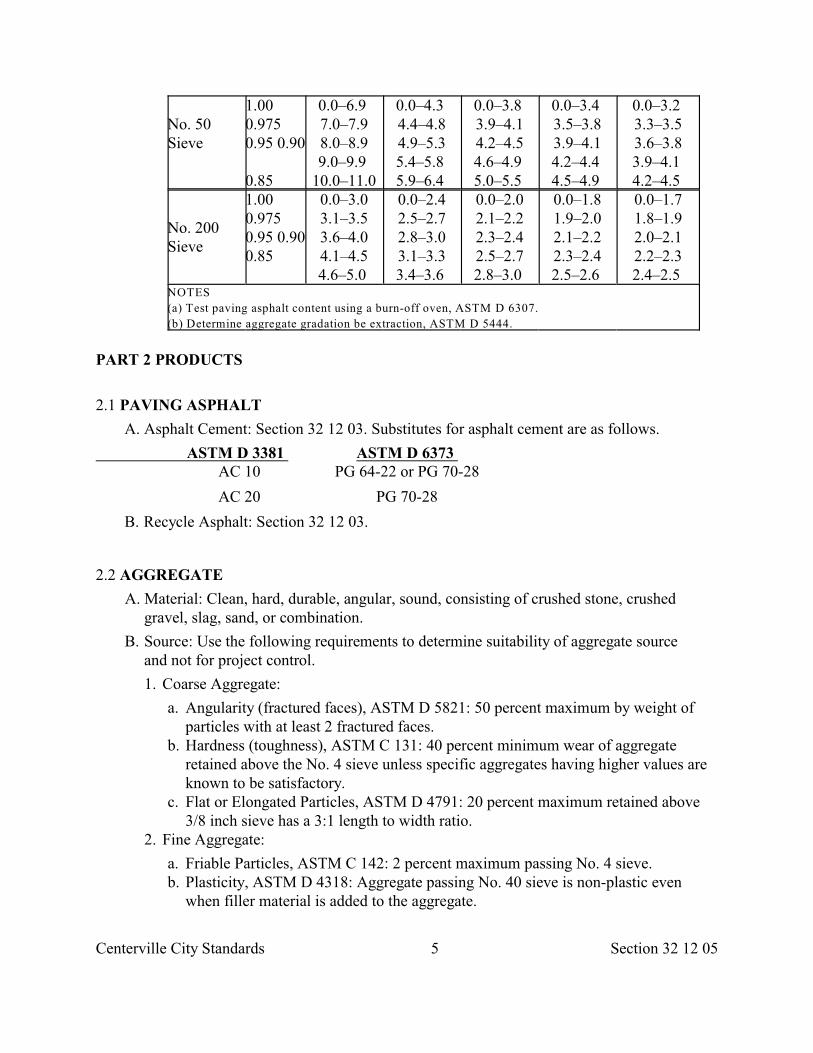
Centerville City Standards 5 Section 32 12 05
No. 50Sieve
1.00 0.9750.95 0.90
0.85
0.0–6.9 7.0–7.98.0–8.99.0–9.9
10.0–11.0
0.0–4.3 4.4–4.84.9–5.35.4–5.8 5.9–6.4
0.0–3.8 3.9–4.14.2–4.54.6–4.9 5.0–5.5
0.0–3.4 3.5–3.83.9–4.14.2–4.4 4.5–4.9
0.0–3.2 3.3–3.53.6–3.83.9–4.1 4.2–4.5
No. 200Sieve
1.000.9750.95 0.900.85
0.0–3.03.1–3.53.6–4.04.1–4.54.6–5.0
0.0–2.42.5–2.72.8–3.03.1–3.33.4–3.6
0.0–2.02.1–2.22.3–2.42.5–2.72.8–3.0
0.0–1.81.9–2.02.1–2.22.3–2.42.5–2.6
0.0–1.71.8–1.92.0–2.12.2–2.32.4–2.5
NOTES
(a) Test paving asphalt content using a burn-off oven, ASTM D 6307.
(b) Determine aggregate gradation be extraction, ASTM D 5444.
PART 2 PRODUCTS
2.1 PAVING ASPHALT
A. Asphalt Cement: Section 32 12 03. Substitutes for asphalt cement are as follows.
ASTM D 3381 ASTM D 6373 AC 10 PG 64-22 or PG 70-28
AC 20 PG 70-28
B. Recycle Asphalt: Section 32 12 03.
2.2 AGGREGATE
A. Material: Clean, hard, durable, angular, sound, consisting of crushed stone, crushedgravel, slag, sand, or combination.
B. Source: Use the following requirements to determine suitability of aggregate sourceand not for project control.
1. Coarse Aggregate:
a. Angularity (fractured faces), ASTM D 5821: 50 percent maximum by weight ofparticles with at least 2 fractured faces.
b. Hardness (toughness), ASTM C 131: 40 percent minimum wear of aggregateretained above the No. 4 sieve unless specific aggregates having higher values areknown to be satisfactory.
c. Flat or Elongated Particles, ASTM D 4791: 20 percent maximum retained above3/8 inch sieve has a 3:1 length to width ratio.
2. Fine Aggregate:
a. Friable Particles, ASTM C 142: 2 percent maximum passing No. 4 sieve. b. Plasticity, ASTM D 4318: Aggregate passing No. 40 sieve is non-plastic even
when filler material is added to the aggregate.
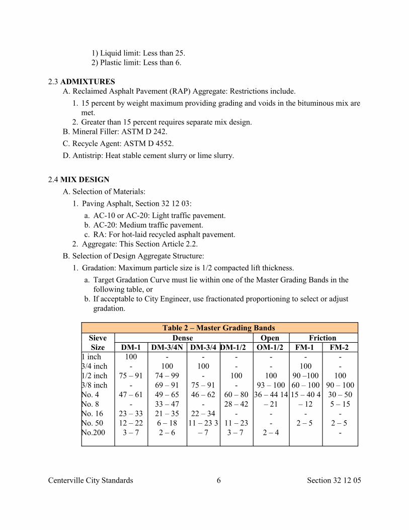
Centerville City Standards 6 Section 32 12 05
1) Liquid limit: Less than 25.2) Plastic limit: Less than 6.
2.3 ADMIXTURES A. Reclaimed Asphalt Pavement (RAP) Aggregate: Restrictions include.
1. 15 percent by weight maximum providing grading and voids in the bituminous mix aremet.
2. Greater than 15 percent requires separate mix design. B. Mineral Filler: ASTM D 242.
C. Recycle Agent: ASTM D 4552.
D. Antistrip: Heat stable cement slurry or lime slurry.
2.4 MIX DESIGN
A. Selection of Materials:
1. Paving Asphalt, Section 32 12 03:
a. AC-10 or AC-20: Light traffic pavement. b. AC-20: Medium traffic pavement. c. RA: For hot-laid recycled asphalt pavement.
2. Aggregate: This Section Article 2.2.
B. Selection of Design Aggregate Structure:
1. Gradation: Maximum particle size is 1/2 compacted lift thickness.
a. Target Gradation Curve must lie within one of the Master Grading Bands in thefollowing table, or
b. If acceptable to City Engineer, use fractionated proportioning to select or adjustgradation.
Table 2 – Master Grading Bands SieveSize
Dense Open Friction DM-1 DM-3/4N DM-3/4 DM-1/2 OM-1/2 FM-1 FM-2
1 inch3/4 inch1/2 inch3/8 inchNo. 4No. 8No. 16No. 50No.200
100-
75 – 91-
47 – 61-
23 – 3312 – 223 – 7
-100
74 – 9969 – 9149 – 6533 – 4721 – 356 – 182 – 6
-100
-75 – 9146 – 62
-22 – 34
11 – 23 3– 7
--
100-
60 – 8028 – 42
-11 – 233 – 7
--
10093 – 100
36 – 44 14– 21
--
2 – 4
-100
90 –10060 – 10015 – 40 4
– 12-
2 – 5
--
10090 – 10030 – 505 – 15
-2 – 5
-
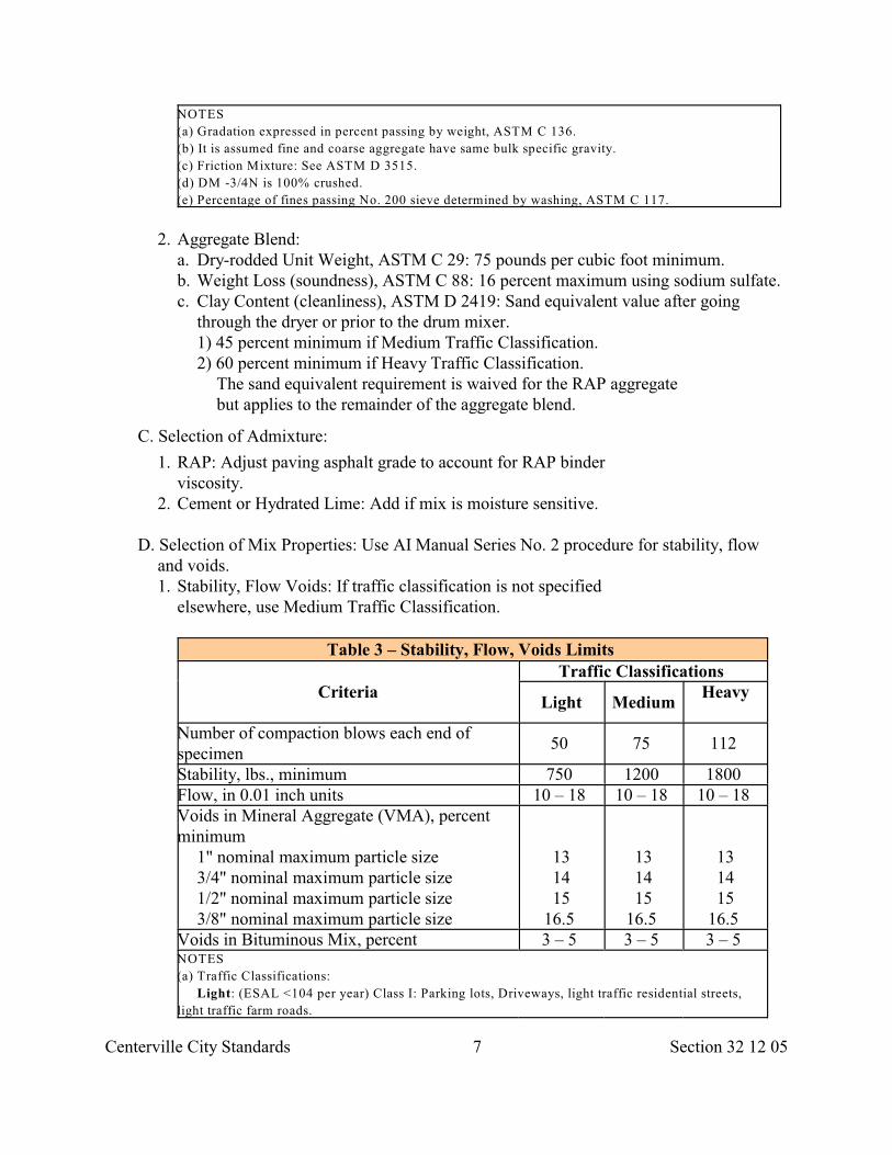
Centerville City Standards 7 Section 32 12 05
NOTES
(a) Gradation expressed in percent passing by weight, ASTM C 136.
(b) It is assumed fine and coarse aggregate have same bulk specific gravity.
(c) Friction Mixture: See ASTM D 3515.
(d) DM -3/4N is 100% crushed.
(e) Percentage of fines passing No. 200 sieve determined by washing, ASTM C 117.
2. Aggregate Blend: a. Dry-rodded Unit Weight, ASTM C 29: 75 pounds per cubic foot minimum. b. Weight Loss (soundness), ASTM C 88: 16 percent maximum using sodium sulfate. c. Clay Content (cleanliness), ASTM D 2419: Sand equivalent value after going
through the dryer or prior to the drum mixer. 1) 45 percent minimum if Medium Traffic Classification. 2) 60 percent minimum if Heavy Traffic Classification.
The sand equivalent requirement is waived for the RAP aggregatebut applies to the remainder of the aggregate blend.
C. Selection of Admixture:
1. RAP: Adjust paving asphalt grade to account for RAP binderviscosity.
2. Cement or Hydrated Lime: Add if mix is moisture sensitive.
D. Selection of Mix Properties: Use AI Manual Series No. 2 procedure for stability, flowand voids. 1. Stability, Flow Voids: If traffic classification is not specified
elsewhere, use Medium Traffic Classification.
Table 3 – Stability, Flow, Voids Limits
CriteriaTraffic Classifications
Light MediumHeavy
Number of compaction blows each end ofspecimen
50 75 112
Stability, lbs., minimum 750 1200 1800 Flow, in 0.01 inch units 10 – 18 10 – 18 10 – 18 Voids in Mineral Aggregate (VMA), percentminimum
1" nominal maximum particle size3/4" nominal maximum particle size1/2" nominal maximum particle size3/8" nominal maximum particle size
131415
16.5
131415
16.5
131415
16.5 Voids in Bituminous Mix, percent 3 – 5 3 – 5 3 – 5 NOTES
(a) Traffic Classifications:
Light: (ESAL <104 per year) Class I: Parking lots, Driveways, light traffic residential streets,
light traffic farm roads.
Centerville City Standards 8 Section 32 12 05
Medium: (ESAL between 104 and 106 per year) Class II: Residential streets, rural farm and
residential roads. Class III: Urban minor collector streets, rural minor collector roads.
Heavy: (ESAL >106 per year) Class IV: Urban minor arterial and light industrial and light
industrial streets, rural major collector and minor arterial highways. Class V: Urban major
arterial and heavy industrial streets, freeways, expressways, arterial highways, rural interstate
and other principal arterial highways.
(b) Stability, Flow, Voids: ASTM D 5581.
(c) VMA: ASTM D 3203
(d) Nominal maximum particle size is the largest sieve size listed in this Section upon which any
material is retained.
2. Dust to Asphalt Ratio: 0.8 to 1.6. 3. Moisture Sensitivity, ASTM D 4867: Tensile strength ratio less than 0.80 using freeze-
thaw conditioning. Test specimen shall be 150 mm in diameter and 95 mm in heightand compacted at 7 percent plus or minus 1 percent air voids)
4. Rut Susceptibility, AASHTO T 324: Maximum rut depth is 10 mm at 20,000 passes.
2.5 SOURCE QUALITY CONTROL
A. General: Collect samples, ASTM D 3665. Do not change sampling points.
1. Aggregate sampling, ASTM D 75. 2. Paving asphalt sampling, ASTM D 140. Test for viscosity and penetration.
B. Asphalt-Aggregate Mix: Sample, ASTM D 979. Test for the following.
1. Air voids, ASTM D 3203 or ASTM D 5581. 2. Paving asphalt content, ASTM D 6307. 3. Aggregate gradation, ASTM D 5444. 4. Tensile strength of bitumen-aggregate mixtures, ASTM D 4867.
C. Mixing Plant: ASTM D 3515.
PART 3 EXECUTION
3.1 INSTALLATION
A. Roadway paving, Section 32 12 17.
B. Patching, Section 33 05 25.
END OF SECTION
Centerville City Standards 1 Section 32 12 06
SECTION 32 12 06
SUPERPAVE
PART 1 GENERAL
1.1 SECTION INCLUDES A. Composition of performance grade asphalt -aggregate mix.
1.2 REFERENCES A. AASHTO T304: Uncompacted Void Content of Fine Aggregate
B. AASHTO T312: Standard Method of Test for Preparing and Determining theDensity of Hot-Mix Asphalt (HMA) Specimens by Means of the Superpave GyratoryCompactor.
C. AASHTO T 324: Hamburg Wheel-track Testing of Compacted Hot-Mix Asphalt (HMA).
D. AI SP-2: Superpave Series No. 2.
E. ASTM C 29: Standard Test Method for Unit Weight and Voids in Aggregate.
F. ASTM C 88: Standard Test Method for Soundness of Aggregates by Use of SodiumSulfate or Magnesium Sulfate.
G. ASTM C 131: Standard Test Method for Resistance to Degradation of Small-SizeCoarse Aggregate by Abrasion and Impact in the Los Angeles Machine.
H. ASTM C 142: Standard Test Method for Clay Lumps and Friable Particles inAggregates.
I. ASTM C 242: Standard Specification for Mineral Filler for Bituminous PavingMixtures.
J. ASTM D 75: Standard Practice for Sampling Aggregates.
K. ASTM D 140: Standard Practice for Sampling Bituminous Materials.
L. ASTM D 979: Standard Methods for Sampling Bituminous Paving Mixtures.
M. ASTM D 2041: Standard Test Method for Theoretical Maximum Specific Gravityof Bituminous Paving Mixtures.
N. ASTM D 2419: Standard Test Method for Sand Equivalent Value of Soils and FineAggregate.
O. ASTM D 3203: Standard Test Method for Percent Air Voids in Compacted Denseand Open Bituminous Paving Mixtures.
P. ASTM D 3515: Standard Specification for Hot-Mixed, Hot-Laid BituminousPaving Mixtures.
Q. ASTM D 3665: Standard Practice for Random Sampling of
Centerville City Standards 2 Section 32 12 06
Construction Materials.R. ASTM D 3666: Standard Specification for Minimum Requirements for Agencies
Testing and Inspecting Bituminous Paving Materials.
S. ASTM D 4318: Standard Test Method for Liquid Limit, Plastic Limit, and PlasticityIndex of Soils.
T. ASTM D 4552: Standard Practice for Classifying Hot-Mix Recycling Agents.
U. ASTM D 4791: Standard Test Method for Flat or Elongated Particles in CoarseAggregate.
V. ASTM D 4867: Standard Test Method for Effect of Moisture on Asphalt Concrete PavingMixtures.
W. ASTM D 5444: Standard Method for Mechanical Size Analysis of ExtractedAggregate.
X. ASTM D 5821: Standard Test Method for Determining the Percentage of FracturedParticles in Coarse Aggregate.
Y. ASTM D 6307: Standard Test Method for Asphalt Content of Hot-Mix Asphalt byIgnition Method.
1.3 DEFINITIONS
A. Asphalt-Aggregate Designator: Alpha-numeric code that indicates nominal maximumsize of aggregate, and type and grade of asphalt in aggregate-asphalt mix. For example;"12.5 PG70-28" means aggregate-asphalt mix shall be composed of an aggregategradation with a 12.5 mm nominal maximum size and a performance grade asphalt binderdesigned to perform between temperatures of 70 deg C. and –28 deg C.
B. ESAL (acronym for equivalent single axle load): Number used in designingPavement thickness. It relates axle load of any mass and number to an equivalentnumber (18,000 lb).
C. Mean of Deviations: Defined in Section 32 11 23.
D. Nominal Maximum Size: One sieve size larger than first sieve size retaining more than10 percent of the Sample. The nominal maximum size sieve will retain a minimum of 0and a maximum of 10 percent of the sample. Maximum size is one sieve size largerthan the nominal maximum size.
1.4 SUBMITTALS A. Quality Assurance: Submit names, certification levels, and years of experience of
testing agency’s field technicians that are assigned to the Work. Verify laboratorycomplies with ASTM standards.
B. Mix Design: Submit.
1. Date of mix design. If older than 365 days, recertify mix design. 2. Paving asphalt source, type, and chemical composition.
Centerville City Standards 3 Section 32 12 06
3. Nominal maximum size of aggregate. 4. Temperature of mix at plant and in the field for for optimum field compaction. 5. Paving asphalt target, dust to asphalt ratio, rut susceptibility, moisture sensitivity
(tensile strength), voids in the mineral aggregate (VMA) and voids filled with asphalt (VFA).
6. RAP, mineral filler, antistrip, and recycle agent percentages. 7. Compaction at Nmax.
C. Pre-approved mix design, submit name and address of Supplier.
D. Before changing mix design, submit a new design and give City Engineer 10 days toevaluate the changes.
E. Source Quality Control Inspections and Testing Report: If requested, submit reportdescribing Developer’s and Supplier’s quality control activities and test results.
1.5 QUALITY ASSURANCE
A. Use a laboratory that follows and complies with ASTM D 3666.
B. Do not change aggregate source or paving asphalt source without City Engineer’swritten approval.
C. Do not use non-complying sources.
1.6 ACCEPTANCE
A. General:
1. Acceptance is by Lot. One Lot is one day’s production.
B. Installation: Accepted as specified in Section 32 12 16.
C. Materials:
1. At the Source:
a. Aggregate: Verify gradation prior to the drum mixer or after going through the drier. b. Paving Asphalt: See Section 32 12 03 provisions. c. Mix: 325 deg. F. maximum in transport vehicle. 2. At the Site:
a. One sub-lot is 500 tons. b. Sampling: Two random samples per sub-lot. Location as follows.
1) Behind paver before compaction, or 2) Where sub-lot exhibits non-uniform appearance.
3. At the Laboratory: a. Air Voids:
1) Basis of evaluation is laboratory compacted samples (not field compactedsamples).
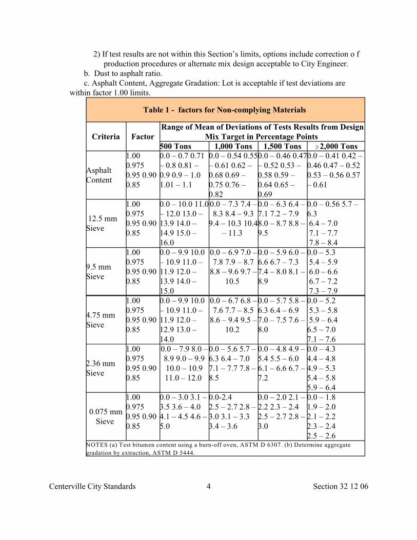
Centerville City Standards 4 Section 32 12 06
2) If test results are not within this Section’s limits, options include correction o fproduction procedures or alternate mix design acceptable to City Engineer.
b. Dust to asphalt ratio. c. Asphalt Content, Aggregate Gradation: Lot is acceptable if test deviations are
within factor 1.00 limits.
Table 1 - factors for Non-complying Materials
Criteria FactorRange of Mean of Deviations of Tests Results from Design
Mix Target in Percentage Points 500 Tons 1,000 Tons 1,500 Tons $2,000 Tons
AsphaltContent
1.000.9750.95 0.900.85
0.0 – 0.7 0.71– 0.8 0.81 –0.9 0.9 – 1.01.01 – 1.1
0.0 – 0.54 0.55– 0.61 0.62 –0.68 0.69 –0.75 0.76 –0.82
0.0 – 0.46 0.47– 0.52 0.53 –0.58 0.59 –0.64 0.65 –0.69
0.0 – 0.41 0.42 –0.46 0.47 – 0.520.53 – 0.56 0.57– 0.61
12.5 mmSieve
1.000.9750.95 0.900.85
0.0 – 10.0 11.0– 12.0 13.0 –13.9 14.0 –14.9 15.0 –16.0
0.0 – 7.3 7.4 –8.3 8.4 – 9.3
9.4 – 10.3 10.4– 11.3
0.0 – 6.3 6.4 –7.1 7.2 – 7.98.0 – 8.7 8.8 –9.5
0.0 – 0.56 5.7 –6.3 6.4 – 7.0 7.1 – 7.7 7.8 – 8.4
9.5 mmSieve
1.000.9750.95 0.900.85
0.0 – 9.9 10.0– 10.9 11.0 –11.9 12.0 –13.9 14.0 –15.0
0.0 – 6.9 7.0 –7.8 7.9 – 8.7
8.8 – 9.6 9.7 –10.5
0.0 – 5.9 6.0 –6.6 6.7 – 7.37.4 – 8.0 8.1 –8.9
0.0 – 5.3 5.4 – 5.9 6.0 – 6.6 6.7 – 7.2 7.3 – 7.9
4.75 mmSieve
1.000.9750.95 0.900.85
0.0 – 9.9 10.0– 10.9 11.0 –11.9 12.0 –12.9 13.0 –14.0
0.0 – 6.7 6.8 –7.6 7.7 – 8.5
8.6 – 9.4 9.5 –10.2
0.0 – 5.7 5.8 –6.3 6.4 – 6.97.0 – 7.5 7.6 –8.0
0.0 – 5.2 5.3 – 5.8 5.9 – 6.4 6.5 – 7.07.1 – 7.6
2.36 mmSieve
1.000.9750.95 0.900.85
0.0 – 7.9 8.0 –8.9 9.0 – 9.910.0 – 10.911.0 – 12.0
0.0 – 5.6 5.7 –6.3 6.4 – 7.07.1 – 7.7 7.8 –8.5
0.0 – 4.8 4.9 –5.4 5.5 – 6.06.1 – 6.6 6.7 –7.2
0.0 – 4.34.4 – 4.84.9 – 5.35.4 – 5.85.9 – 6.4
0.075 mmSieve
1.000.9750.95 0.900.85
0.0 – 3.0 3.1 –3.5 3.6 – 4.04.1 – 4.5 4.6 –5.0
0.0-2.42.5 – 2.7 2.8 –3.0 3.1 – 3.33.4 – 3.6
0.0 – 2.0 2.1 –2.2 2.3 – 2.42.5 – 2.7 2.8 –3.0
0.0 – 1.81.9 – 2.02.1 – 2.22.3 – 2.42.5 – 2.6
NOTES (a) Test bitumen content using a burn-off oven, ASTM D 6307. (b) Determine aggregate
gradation by extraction, ASTM D 5444.
Centerville City Standards 5 Section 32 12 06
PART 2 PRODUCTS
2.1 PAVING ASPHALT A. Performance Grade Asphalt Binder (PGAB): Section 32 12 03.
1. Blending with polymers or natural asphalts is City Engineer’s choice. 2. Do not use acid blends without documentation supporting need. 3. As a rule of thumb, if the two numbers in an asphalt binder designation are added
1) 40 percent maximum if ESALs are less than 0.3 million. 2) 35 percent maximum if ESALs are more than 0.3 million.
c. Flat and Elongated Particles, ASTM D 4791: 20 percent maximum retained above the 9.5 mm sieve has a 3:1 length to width ratio.
2. Fine Aggregate:
a. Angularity, AASHTO T304: 45 percent minimum uncompacted void content. b. Friable Particles, ASTM C 142: 2 percent maximum by weight passing 4.75 mm
sieve. c. Plasticity, ASTM D 4318: Aggregate passing 4.75 mm sieve is non-plastic even
when filler material is added to the aggregate. 1) Liquid limit: Less than 25. 2) Plastic limit: Less than 6.
2.3 ADMIXTURES
A. Reclaimed Asphalt Pavement (RAP) Aggregate: Restrictions include. 1. 15 percent by weight maximum providing grading, VMA and VFA are met. 2. Greater than 15 percent requires separate mix design.
B. Mineral Filler: ASTM D 242.
C. Recycle Agent: ASTM D 4552. D. Antistrip: Heat stable, cement slurry, or lime slurry.
2.4 MIX DESIGN A. Selection of Materials:
1. Paving Asphalt. Section 32 12 03. a. PG70-28: Less than 3 million EASLs. b. PG70-28: 3 million to 30 million EASLs. 2. Aggregate: This Section Article 2.2.
B. Selection of Design Aggregate Structure. 1. Gradation: Maximum particle size is 1/4 compacted lift thickness.
a. Target Gradation Curve must lie within one of the following Master Grading Bands. It must lie below the restricted zone in traffic class IV and traffic class V (Table 3 Section 32 12 05). In all other classes it may lie above, below, or pass through the zone.
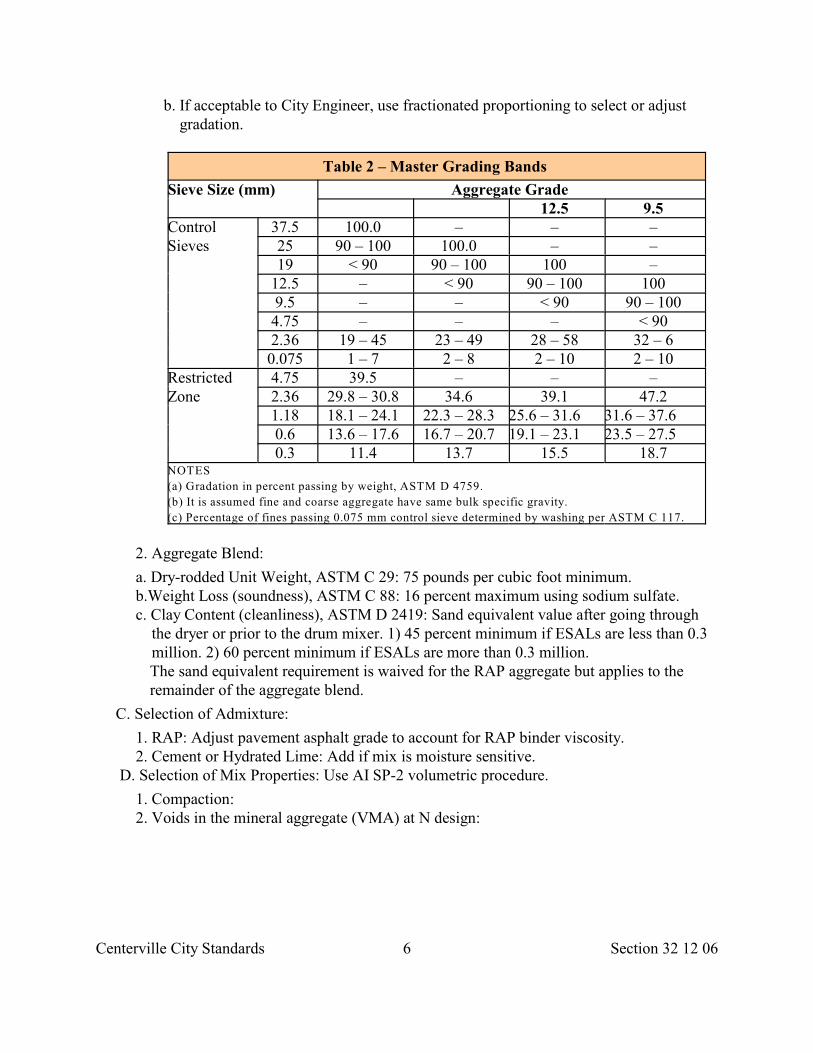
Centerville City Standards 6 Section 32 12 06
b. If acceptable to City Engineer, use fractionated proportioning to select or adjust gradation.
Table 2 – Master Grading Bands
Sieve Size (mm) Aggregate Grade 12.5 9.5
ControlSieves
37.5 100.0 – – – 25 90 – 100 100.0 – – 19 < 90 90 – 100 100 –
12.5 – < 90 90 – 100 100 9.5 – – < 90 90 – 100 4.75 – – – < 90 2.36 19 – 45 23 – 49 28 – 58 32 – 6 0.075 1 – 7 2 – 8 2 – 10 2 – 10
RestrictedZone
4.75 39.5 – – – 2.36 29.8 – 30.8 34.6 39.1 47.2 1.18 18.1 – 24.1 22.3 – 28.3 25.6 – 31.6 31.6 – 37.6 0.6 13.6 – 17.6 16.7 – 20.7 19.1 – 23.1 23.5 – 27.5 0.3 11.4 13.7 15.5 18.7
NOTES
(a) Gradation in percent passing by weight, ASTM D 4759.
(b) It is assumed fine and coarse aggregate have same bulk specific gravity.
(c) Percentage of fines passing 0.075 mm control sieve determined by washing per ASTM C 117.
2. Aggregate Blend:
a. Dry-rodded Unit Weight, ASTM C 29: 75 pounds per cubic foot minimum. b.Weight Loss (soundness), ASTM C 88: 16 percent maximum using sodium sulfate. c. Clay Content (cleanliness), ASTM D 2419: Sand equivalent value after going through the dryer or prior to the drum mixer. 1) 45 percent minimum if ESALs are less than 0.3 million. 2) 60 percent minimum if ESALs are more than 0.3 million.
The sand equivalent requirement is waived for the RAP aggregate but applies to theremainder of the aggregate blend.
C. Selection of Admixture:
1. RAP: Adjust pavement asphalt grade to account for RAP binder viscosity. 2. Cement or Hydrated Lime: Add if mix is moisture sensitive. D. Selection of Mix Properties: Use AI SP-2 volumetric procedure.
1. Compaction: 2. Voids in the mineral aggregate (VMA) at N design:
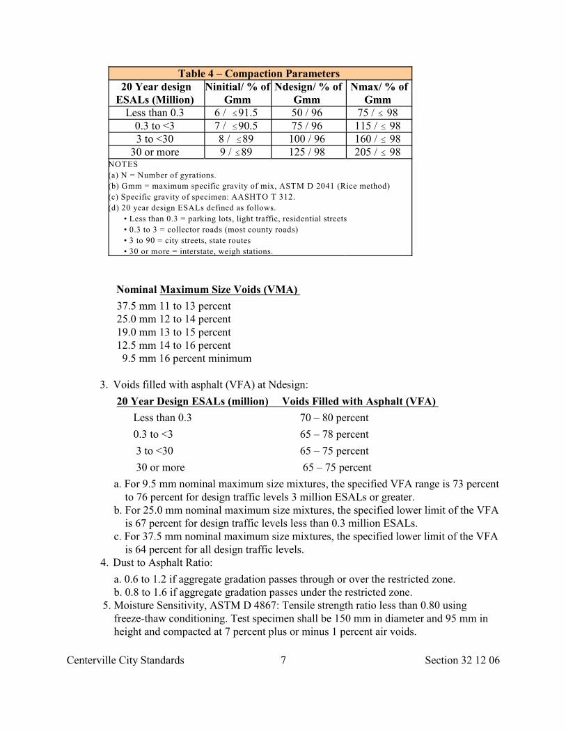
Centerville City Standards 7 Section 32 12 06
Table 4 – Compaction Parameters 20 Year design
ESALs (Million) Ninitial/ % of
GmmNdesign/ % of
Gmm Nmax/ % of
Gmm Less than 0.3 6 / #91.5 50 / 96 75 / # 98
0.3 to <3 7 / #90.5 75 / 96 115 / # 98 3 to <30 8 / #89 100 / 96 160 / # 98
30 or more 9 / #89 125 / 98 205 / # 98 NOTES
(a) N = Number of gyrations.
(b) Gmm = maximum specific gravity of mix, ASTM D 2041 (Rice method)
(c) Specific gravity of specimen: AASHTO T 312.
(d) 20 year design ESALs defined as follows.
• Less than 0.3 = parking lots, light traffic, residential streets
• 0.3 to 3 = collector roads (most county roads)
• 3 to 90 = city streets, state routes
• 30 or more = interstate, weigh stations.
Nominal Maximum Size Voids (VMA)
37.5 mm 11 to 13 percent 25.0 mm 12 to 14 percent 19.0 mm 13 to 15 percent
12.5 mm 14 to 16 percent 9.5 mm 16 percent minimum
3. Voids filled with asphalt (VFA) at Ndesign:
20 Year Design ESALs (million) Voids Filled with Asphalt (VFA)
Less than 0.3 70 – 80 percent
0.3 to <3 65 – 78 percent
3 to <30 65 – 75 percent
30 or more 65 – 75 percent
a. For 9.5 mm nominal maximum size mixtures, the specified VFA range is 73 percent to 76 percent for design traffic levels 3 million ESALs or greater.
b. For 25.0 mm nominal maximum size mixtures, the specified lower limit of the VFA is 67 percent for design traffic levels less than 0.3 million ESALs.
c. For 37.5 mm nominal maximum size mixtures, the specified lower limit of the VFA is 64 percent for all design traffic levels.
4. Dust to Asphalt Ratio:
a. 0.6 to 1.2 if aggregate gradation passes through or over the restricted zone. b. 0.8 to 1.6 if aggregate gradation passes under the restricted zone.
5. Moisture Sensitivity, ASTM D 4867: Tensile strength ratio less than 0.80 using freeze-thaw conditioning. Test specimen shall be 150 mm in diameter and 95 mm in height and compacted at 7 percent plus or minus 1 percent air voids.
Centerville City Standards 8 Section 32 12 06
6. Rut Susceptibility, AASHTO T 324: Maximum rut depth is 10 mm at 20,000 passes.
2.5 SOURCE QUALITY CONTROL
A. General: Collect Samples randomly, ASTM D 3665. Do not change sampling points.
1. Aggregate sampling, ASTM D 75. 2. Paving asphalt sampling, ASTM D 140.
B. Asphalt-aggregate mix sampling, ASTM D 979. Test for
1. Air voids, ASTM D 3203. 2. Paving asphalt content, ASTM D 6307. 3. Aggregate gradation, ASTM D 5444. 4. Tensile strength of bitumen-aggregate mixtures, ASTM D 4867.
C. Mixing Plant: ASTM D 3515.
PART 3 EXECUTION
3.1 INSTALLATION A. Pavement placement, Section 32 12 17.
B. Pavement restoration, Section 33 05 25.
END OF SECTION
Centerville City Standards 1 Section 32 12 13
SECTION 32 12 13
PRIME COAT
PART 1 GENERAL
1.1 SECTION INCLUDES
A. Application of liquid asphalt to aggregate base prior to placing asphalt concrete or portlandcement concrete Pavement.
B. Placing sand on areas that are over-primed.
1.2 SUBMITTALS
A. Certificate showing asphaltic material complies with Section 32 12 03.
1.3 WEATHER
A. Apply prime coat only when air and roadbed temperatures in the shade are greater than 40deg. F. The temperature restrictions may be waived only upon written authorization fromCity Engineer.
B. Do not apply prime coat during rain, fog, dust, or other unsuitable weather.
PART 2 PRODUCTS
2.1 ASPHALT MATERIAL
A. Select from the following:
1. Slow Cure Cutback Asphalt: Grade SC-70, or SC-250, Section 32 12 03. 2. Medium Cure Cutback Asphalt: Grade MC-30, MC-70, or MC-250, Section 32 12 03. 3. Rapid Cure Cutback Asphalt: Grade RC-1, RC-2, or RC-250, Section 32 12 03.
2.2 SAND
A. Clean natural aggregate passing the No. 4 sieve and retained on the No. 200 Sieve.
PART 3 EXECUTION
3.1 PREPARATION
A. If aggregate base course to be primed contains an appreciable amount of loose material oris excessively dusty; moisten, blade, roll, and recompact to make the surface dense.
Centerville City Standards 2 Section 32 12 13
B. Do not start priming until all free surface moisture has disappeared.
C. Notify residents and business owners 24 hours prior to applying prime coat.
D. Provide pedestrian access across prime coat if required.
3.2 APPLICATION
A. When Pavement surface under Pavement overlay is loosely bonded, apply prime coat at0.10 to 0.50 gallons per square yard to penetrate and seal. Do not flood surface.
B. Cure and dry as long as necessary to attain penetration and evaporation of volatile.
C. Blot over-primed surface by spreading a light, uniform layer of sand.
D. Prime under-primed areas with additional asphalt.
3.3 PROTECTION
A. Protect all structures, including curb and gutter, sidewalks, guardrails and guide postsfrom being spattered or marred. Remove any spattering, over-coating, or marring.
B. Do not discharge bituminous material into borrow pits or gutters.
C. Prevent tracking of prime coat onto adjacent surfaces.
3.4 OPENING TO TRAFFIC AND MAINTENANCE
A. Do not permit traffic to travel over freshly primed surface until prime coat has cured. Ifdetours cannot be provided, restrict operations to a width suitable at least for one-waytraffic over the remaining portion of the road. If one-way traffic is provided, controltraffic by flagging or pilot car operation.
B. After prime coat application, leave work area undisturbed. If prime coat is tacky or tendsto pick up under traffic after 4 hours, blot excess prime coat with blotter sand. Primecoats can be opened to traffic after blotting.
C. Clean and maintain primed surfaces until surface Pavement course is placed.Maintenance includes spreading any necessary additional blotter material, replacing allportions of prime coat that have been destroyed, and patching any break in primedsurfaces.
END OF SECTION

Centerville City Standards 1 Section 32 12 14
SECTION 32 12 14
TACK COAT
PART 1 GENERAL
1.1 SECTION INCLUDES
A. Application of asphaltic material to existing asphalt concrete or portland cementconcrete surfaces preparatory to placing an asphalt concrete Pavement.
1.2 SUBMITTALS
A. Certificate showing asphaltic material complies with Section 32 12 03.
1. Identify water/asphalt dilution ratio. 2. Identify tack coat application rate.
B. Identify asphalt material recommended by fabric manufacturer.
1.3 WEATHER
A. Apply tack coat only when air and roadbed temperatures in the shade are greater than 40deg. F. The temperature restrictions may be waived only upon written authorization fromCity Engineer.
B. Do not apply tack coat during rain, fog, dust, or other unsuitable weather. Do notapply coat to wet surfaces.
1.4 NOTICE
A. Send written notice to residents or business owners 24 hours prior to applying coat.
PART 2 PRODUCTS
2.1 ASPHALT MATERIAL
A. Select from the following.
1. Emulsified Asphalt: Grade MS-1, SS-1 or SS-1h, Section 32 12 03. 2. Cationic Emulsified Asphalt: Grade CSS-1 or CSS-1h, Section 32 12 03. 3. Rapid Cure Cutback Asphalt: Grade RC-70, Section 32 12 03.
PART 3 EXECUTION
3.1 PREPARATION
Centerville City Standards 2 Section 32 12 14
A. Select and advise City Engineer of the type of tack material to be used. B. Clean the surface to be treated free of dust and other foreign material. If flushed, allow
surface to dry. If leaves from trees, blow clean.
C. Provide surface for pedestrian access across tack coat. D. Prevent pedestrians, vehicles, pets, etc., access to tack surfaces.
3.2 APPLICATION A. General:
1. Triple coverage by spray bar required. Stop application if any nozzle is not workingproperly.
2. Apply tack only to area covered with asphalt concrete in the same day. B. Application rate: Typically as follows.
1. Emulsions, 0.05 to 0.15 gallons per square yard. 2. Cutback, City Engineer’s choice.
C. Tack Substrate for Fabric Application: Comply with manufacturer’s recommendation. Ifnone, then as follows. 1. Dry Pavement surface, 0.20 to 0.30 gallons per square yard. Within street intersections,
on steep grades and in zones where vehicle speed changes are commonplace reduce theapplication rate to no less than 0.20 gallons per square yard.
2. Heavy duty fabrics, 0.30 to 0.40 gallons per square yard.
3.3 PROTECTION A. Protect all surfaces exposed to public view from being spattered or marred. Remove
any spattering, over-coating, or marring.
B. Do not discharge bituminous material into borrow pits or gutters.
3.4 OPENING TO TRAFFIC AND MAINTENANCE
A. Do not permit traffic to travel over the tacked surface until bituminous tack coat has curedor is not picked up by traffic.
B. If detours cannot be provided, restrict operations to a width suitable at least for one-waytraffic over the remaining portion of the road.
C. If one-way traffic is provided, control traffic appropriately.
END OF SECTION
Centerville City Standards 1 Section 32 12 16
SECTION 32 12 16
PLANT-MIX -ASPHALT PAVING
PART 1 GENERAL
1.1 SECTION INCLUDES
A. Place Superpave or plant-mix asphalt concrete in base, leveling and surface courses, oroverlay.
1.2 REFERENCES
A. AASHTO T 324: Hamburg Wheel-track Testing of Compacted Hot-Mix Asphalt(HMA).
B. ASTM D 979: Standard Practice for Sampling Bituminous Paving Mixtures.
C. ASTM D 2041: Standard Test Method for Theoretical Maximum Specific Gravity ofBituminous Paving Mixtures.
D. ASTM D 3549: Standard Test Method for Thickness or Height of CompactedBituminous Paving Mixture Specimens.
E. ASTM D 3665: Standard Practice for Random Sampling ofConstruction Materials.
F. ASTM E 950: Standard Test Method for Measuring the Longitudinal Profile of TraveledSurfaces with an Accelerometer Established Inertial Profiling Reference.
G. ASTM E 1274: Standard Test Method for Measuring Pavement Roughness Using aProfilograph.
1.3 SUBMITTALS
A. Before Delivery: 1. Traffic control plan, Section 01 55 26. 2. Type and number of rollers. 3. Manufacturer's certificate of compliance for paving geotextiles, Refer to Section 31 05
19. 4. Location and name of asphalt concrete production facility. 5. Proof of profilograph and profilograph operator certification.
B. At Delivery: Supply batch ticket identifying. 1. Serial number of ticket. 2. Date and truck number. 3. Job name, location, and mix identification. 4. Type, grade, and weight of asphalt.5 Type, grade, and weight of aggregate.
Centerville City Standards 2 Section 32 12 16
6. Mix design method. C. After Delivery:
1. Profile deviation report. 2. Profile roughness index report. 3. Quality Control Inspections and Testing Report: Upon City Engineer’s request, submit
report describing source and field quality control activities and test results performedby Developer and Developer’s Suppliers.
1.4 QUALITY ASSURANCE
A. Do not change asphalt or aggregate sources until City Engineer accepts new sourceand new mix design.
B. Reject product and work that does not meet requirements of this Section.
C. Remove product found defective after installation and install acceptable product.
D. Foreman of paving crew has completed at least three (3) projects of similar size andnature.
1.5 WEATHER
A. Do not pave until air temperature is 45 deg F. and rising.
B. Cease paving if air temperature falls below 50 deg F.
C. Do not pave if surface is wet or weather is unsuitable.
D. Do not pave if wind or ground cools mix material before compaction.
1.6 NOTICE
A. Send written notice to residents and businesses within affected area at least 3 daysbefore start of paving.
B. Indicate paving time and when new surface can be used.
C. Warn of potential vehicle tow away and other construction issues affectingneighborhood.
D. Should work not occur on specified day, send a new notice.
1.7 ACCEPTANCE
A. General:
1. Acceptance is by Lot. Lot size is specified below. 2. Opening a paved surface to traffic does not constitute acceptance.
B. Mix: Accepted as specified in Section 32 12 05, or Section 32 12 06.
C. Installation:
1. Mix Temperature:
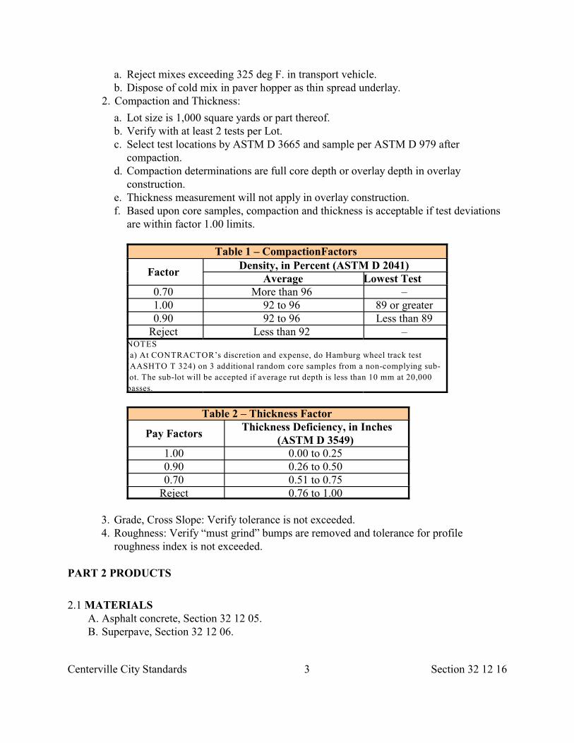
Centerville City Standards 3 Section 32 12 16
a. Reject mixes exceeding 325 deg F. in transport vehicle. b. Dispose of cold mix in paver hopper as thin spread underlay.
2. Compaction and Thickness:
a. Lot size is 1,000 square yards or part thereof. b. Verify with at least 2 tests per Lot. c. Select test locations by ASTM D 3665 and sample per ASTM D 979 after
compaction. d. Compaction determinations are full core depth or overlay depth in overlay
construction. e. Thickness measurement will not apply in overlay construction. f. Based upon core samples, compaction and thickness is acceptable if test deviations
are within factor 1.00 limits.
Table 1 – CompactionFactors
Factor Density, in Percent (ASTM D 2041)
Average Lowest Test 0.70 More than 96 – 1.00 92 to 96 89 or greater 0.90 92 to 96 Less than 89
Reject Less than 92 – NOTES
(a) At CONTRACTOR’s discretion and expense, do Hamburg wheel track test
(AASHTO T 324) on 3 additional random core samples from a non-complying sub-
lot. The sub-lot will be accepted if average rut depth is less than 10 mm at 20,000
passes.
Table 2 – Thickness Factor
Pay Factors Thickness Deficiency, in Inches
(ASTM D 3549) 1.00 0.00 to 0.25 0.90 0.26 to 0.50 0.70 0.51 to 0.75
Reject 0.76 to 1.00
3. Grade, Cross Slope: Verify tolerance is not exceeded. 4. Roughness: Verify “must grind” bumps are removed and tolerance for profile
roughness index is not exceeded.
PART 2 PRODUCTS
2.1 MATERIALS A. Asphalt concrete, Section 32 12 05. B. Superpave, Section 32 12 06.
Centerville City Standards 4 Section 32 12 16
C. Prime coat, Section 32 12 13. D. Tack coat, Section 32 12 14. E. Paving geotextile, Section 31 05 19. F. Paving geogrid, Section 31 05 21.
PART 3 EXECUTION
3.1 CONSTRUCTION EQUIPMENT
A. Lay Down Machine: Use track equipment when operating on fabrics, geogrids orPavement mats hotter than 180 deg. F.
B. Compactors: Steel wheel static or vibratory. Use pneumatic tire roller for intermediaterolling only.
3.2 PREPARATION
A. General:
1. Coordinate utility location. Contact utility companies and other agencies, fordangerous concentration of combustible, flammable, or explosive matter.
2. Lower Street Fixtures if paving machine is not capable of passing over the fixtures. 3. Remove vegetation from cracks, edges and joints. Sweep surface clean. Blow cracks
clean. Remove leaves. 4. Fill cracks and fix Potholes, Section 32 01 17. 5. Stabilize concrete Subgrade slabs.
B. Trees, Plants, Ground Cover:
1. Protect trees, plants and other ground cover from damage. 2. Prune trees, Section 32 01 93 to allow equipment passage underneath. Repair tree
damage. C. Traffic Control:
1. Provide worker and public safety, Section 01 55 26. 2. Apply temporary traffic and lane marking tape or paint after layout has been verified
with City Engineer.D. Aggregate Base Course:
1. Verify base course is placed to grade and compacted. 2. If indicated, follow Section 31 25 00 for herbicide treatment or Section 32 12 13 for
prime coat.
E. Tack Coat: Apply tack coat, Section 32 12 14 if inlay or subbase Pavement surfaceis dirty or older than 24 hours.
3.3 TEMPORARY SURFACING
A. Place, roll, maintain, remove and dispose of temporary surfaces.
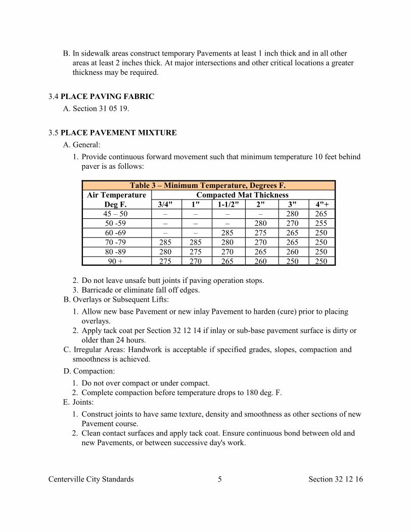
Centerville City Standards 5 Section 32 12 16
B. In sidewalk areas construct temporary Pavements at least 1 inch thick and in all otherareas at least 2 inches thick. At major intersections and other critical locations a greaterthickness may be required.
3.4 PLACE PAVING FABRIC
A. Section 31 05 19.
3.5 PLACE PAVEMENT MIXTURE
A. General:
1. Provide continuous forward movement such that minimum temperature 10 feet behindpaver is as follows:
Table 3 – Minimum Temperature, Degrees F. Air Temperature
Deg F. Compacted Mat Thickness
3/4" 1" 1-1/2" 2" 3" 4"+45 – 50 – – – – 280 265 50 -59 – – – 280 270 255 60 -69 – – 285 275 265 250 70 -79 285 285 280 270 265 250 80 -89 280 275 270 265 260 250 90 + 275 270 265 260 250 250
2. Do not leave unsafe butt joints if paving operation stops. 3. Barricade or eliminate fall off edges.
B. Overlays or Subsequent Lifts:
1. Allow new base Pavement or new inlay Pavement to harden (cure) prior to placingoverlays.
2. Apply tack coat per Section 32 12 14 if inlay or sub-base pavement surface is dirty orolder than 24 hours.
C. Irregular Areas: Handwork is acceptable if specified grades, slopes, compaction andsmoothness is achieved.
D. Compaction:
1. Do not over compact or under compact. 2. Complete compaction before temperature drops to 180 deg. F.
E. Joints:
1. Construct joints to have same texture, density and smoothness as other sections of newPavement course.
2. Clean contact surfaces and apply tack coat. Ensure continuous bond between old andnew Pavements, or between successive day's work.
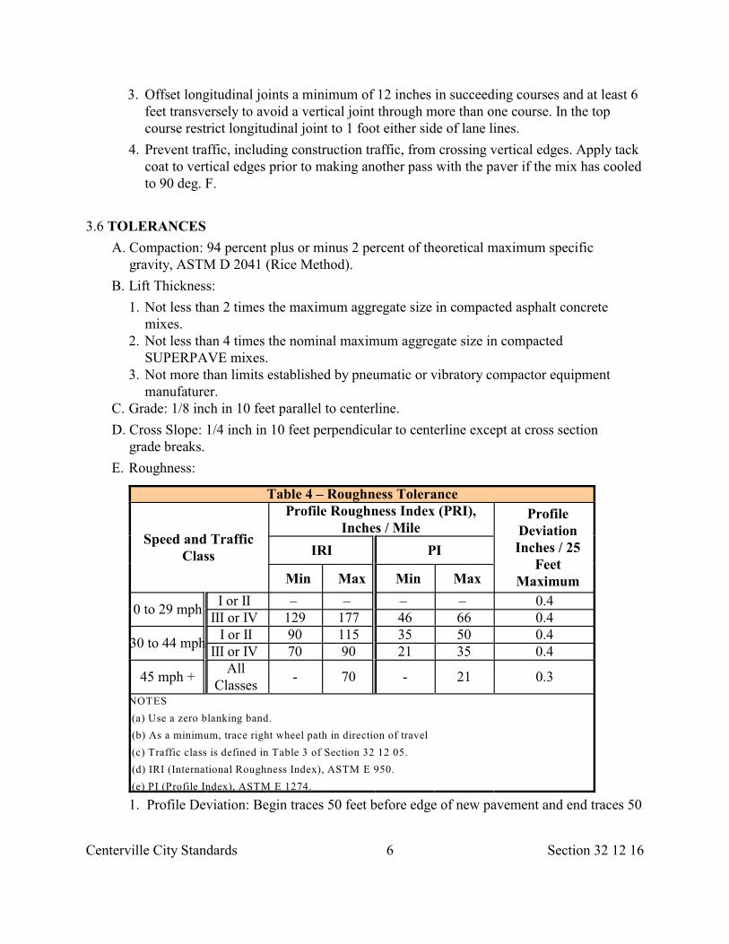
Centerville City Standards 6 Section 32 12 16
3. Offset longitudinal joints a minimum of 12 inches in succeeding courses and at least 6feet transversely to avoid a vertical joint through more than one course. In the topcourse restrict longitudinal joint to 1 foot either side of lane lines.
4. Prevent traffic, including construction traffic, from crossing vertical edges. Apply tackcoat to vertical edges prior to making another pass with the paver if the mix has cooledto 90 deg. F.
3.6 TOLERANCES
A. Compaction: 94 percent plus or minus 2 percent of theoretical maximum specificgravity, ASTM D 2041 (Rice Method).
B. Lift Thickness:
1. Not less than 2 times the maximum aggregate size in compacted asphalt concretemixes.
2. Not less than 4 times the nominal maximum aggregate size in compactedSUPERPAVE mixes.
3. Not more than limits established by pneumatic or vibratory compactor equipmentmanufaturer.
C. Grade: 1/8 inch in 10 feet parallel to centerline.
D. Cross Slope: 1/4 inch in 10 feet perpendicular to centerline except at cross sectiongrade breaks.
E. Roughness:
Table 4 – Roughness Tolerance
Speed and TrafficClass
Profile Roughness Index (PRI),Inches / Mile
ProfileDeviationInches / 25
FeetMaximum
IRI PI
Min Max Min Max
0 to 29 mphI or II – – – – 0.4
III or IV 129 177 46 66 0.4
30 to 44 mphI or II 90 115 35 50 0.4
III or IV 70 90 21 35 0.4
45 mph +All
Classes- 70 - 21 0.3
NOTES
(a) Use a zero blanking band.
(b) As a minimum, trace right wheel path in direction of travel
(c) Traffic class is defined in Table 3 of Section 32 12 05.
(d) IRI (International Roughness Index), ASTM E 950.
(e) PI (Profile Index), ASTM E 1274.
1. Profile Deviation: Begin traces 50 feet before edge of new pavement and end traces 50
Centerville City Standards 7 Section 32 12 16
feet after edge of new pavement. Areas exceeding profile deviation tolerance are “mustgrind” areas.
2. Profile Roughness Index: (PRI)
a. Lot is 0.1 lane mile (528 feet long one lane wide). Add segments shorter than 250feet to preceding Lot. Treat partial segments longer than 250 feet as a Lot.
b. Exclude from the Lot are turn lanes, parking lanes, medians, street fixtures, crownsof intersecting streets, bridge decks, grades greater than 8 percent, and verticalcurves less than 1,000 feet radius (including super-elevation transitions).
3.7 PROTECTION AND REPAIR
A. Protection.
1. Protect all structures, including curb, gutter, sidewalks, guard rails and guide posts. 2. Remove spatter, over-coat, or mar. 3. Do not discharge bituminous materials into borrow pits or gutters. 4. Protect hot pavement from traffic until mixture has cooled enough not to become
marked. 5. Protect neighborhood, storm drains and down-stream fish habitat.
B. Repair.
1. Corrective Action for Profile Deviations (“Must Grinds”): Grinding is acceptable,Section 02 41 14. Apply Section 32 12 03 cationic or anionic emulsion and sandfriction blotter over grind areas.
2. Corrective Action for Profile Roughness Index: Grinding is acceptable. Skin patchfor depressions is not acceptable. Raise depressions by milling and inlay. Re-profile corrected segments to verify index meets tolerance. Apply a Section 32 1203 cationic or anionic emulsion and sand friction blotter over grind areas.
3. When thickness is deficient, place additional material over deficient areas. DONOT skin patch. Mill for inlay if necessary.
4. Defective Joints, Seams, Edges: Repair. 5. Unacceptable Paving: Remove and replace.
END OF SECTION
Centerville City Standards 1 Section 32 12 17
SECTION 32 12 17
COLD-MIX -ASPHALT PAVING
PART 1 GENERAL
1.1 SECTION INCLUDES A. Placing cold mix asphalt concrete in base, leveling, and surface courses.
B. Asphalt concrete material is not specified in this Section. Refer to Section 32 12 05or 32 12 06.
1.2 REFERENCES
A. ASTM D 1461: Standard Test Method for Moisture or Volatile Distillates inBituminous Paving Mixtures.
B. ASTM D 2041: Standard Test Method for Theoretical Maximum Specific Gravityof Bituminous Paving Mixtures.
C. ASTM D 2170: Standard Test Method for Kinematic Viscosity of Asphalts(Bitumens).
D. ASTM D 2399: Standard Practice for Selection of Cutback Asphalts.
E. ASTM D 3628: Standard Practice for Selection and Use of Emulsified Asphalts.
F. ASTM D 5581: Standard Test Method for Resistance to Plastic flow of BituminousMixtures Using Marshall Apparatus (6 inch-Diameter Specimen).
1.3 SUBMITTALS
A. Traffic control plan, Section 01 55 26.
B. Laboratory mix design, Section 32 12 05.
C. Batch Delivery Tickets: Submit ticket for each batch delivered to the Work site. Includeinformation specified in Section 32 12 17.
1.4 WEATHER
A. Section 32 12 17.
1.5 NOTICE
A. Section 32 12 17
1.6 ACCEPTANCE
A. Section 32 12 17.
Centerville City Standards 2 Section 32 12 17
PART 2 PRODUCTS
2.1 MATERIALS
A. Paving asphalt, Section 32 12 03: Emulsified asphalt or medium curing cutback asphalt.If type is not indicated City Engineer is to select as follows:
1. Emulsified Asphalt, ASTM D 3628. 2. Cutback Asphalt, ASTM D 2399.
B. Aggregate, Section 32 12 05: Use an aggregate containing not more than the 2 percentmoisture. If more, dry before asphalt is applied. An exception may be made for unusuallyporous material, when laboratory tests indicate excess moisture will not produce anunstable mix.
PART 3 EXECUTION
3.1 CONSTRUCTION EQUIPMENT
A. Laydown Machine: Use track equipment when operating on fabrics or geogrid.
B. Compactors: Steel wheeled static or vibratory. Any use of a pneumatic tire roller is forintermediate compaction only.
3.2 PREPARATION A. Trees, Plants, Ground Cover: 1. Protect trees, plants and other ground cover from damage.
2. Prune trees, Section 32 01 93 to allow equipment passage underneath. Repair tree damage. B. Traffic Control:
1. Control pedestrian and vehicular traffic, Section 01 55 26. 2. Apply temporary traffic and lane marking tape or paint after layout and placement has
been verified with City Engineer.
3.3 PREPARATION OF AGGREGATE A. On unpaved surfaces, prime coat whole roadway surface receiving cold-mix application,
Section 32 12 13.
B. Place aggregate to be mixed with bitumen on the prepared base in a uniformwindrow or windrows.
C. Notify City Engineer 48 hours in advance of applying the bituminous material to permitcheck of the aggregate with respect to volume, moisture content, and unit weight, andthe proper amount of bituminous material to be used.
3.4 PROPORTIONING AND MIXING
A. Unless specified otherwise, method of mixing may be selected from a traveling mixer
Centerville City Standards 3 Section 32 12 17
method, stationary mixer method, or blade mixing method.
B. Traveling Mixer Method:
1. Accomplish mixing by means of mixer that will thoroughly blend the aggregate and bitumen. Use metering devices that will accurately introduce required quantity of bitumen during the mixing process. Produce a satisfactory mixture that is uniform in appearance, texture and bitumen content, and free from pockets of segregated aggregates.
2. When necessary, supplement travel plant mixing with blade mixing to obtain the desired degree of aeration of the mix. Continue mixing until not more than 50 percent of the original volatiles present in the bituminous material remain in the mix, ASTM D 1461.
C. Blade Method:
1. Spread the windrowed aggregate on the prepared base, after which, uniformly apply the bituminous material over the aggregate.
2. Apply the bituminous material in 2 or more applications over a section of definite limits. Limit the amount of bitumen spread in any 1 application to 0.50 gallon per square yard. Exercise care to avoid overlapping of spreads onto adjoining sections. Immediately after each application, partially mix the bituminous material with the aggregate.
3. After the last application of bituminous material and partial mixing, windrow the entire mass of bitumen and aggregate and mix by blading the material from side to side of the roadway. Blade to produce a satisfactory mixture that is uniform in appearance, texture, and bitumen content, and free from pockets of segregated aggregates and continue until not more than 50 percent of the original volatiles present in the bitumen remain in the mix, ASTM D 1461. While mixing, take care to avoid cutting into the underlying base course or contaminating the bituminous mixture with earth or other foreign matter.
D. Stationary Mixer Method:
1. Dry the aggregate to the optimum moisture content prior to mixing. Use the same application of bituminous material and mixing as required for traveling mixer.
2. After mixing, haul and place the material on the roadway surface in windrows. All requirements as to uniformity, percent of volatiles, and textures are as required for traveling mixer which may require supplemental blade mixing.
3.5 TEMPERATURE CONTROL
A. Maintain the temperature range of the asphalt road mix material at the time ofapplication so that the viscosity will be between 50 and 200 centistokes, ASTM D2170.
3.6 PLACING PAVEMENT MIXTURE A. At the end of each day's work or when the work is interrupted by adverse weather
conditions, blade all loose material into a windrow, whether mixing is completed or not.
Centerville City Standards 4 Section 32 12 17
Do not leave material spread on the roadbed overnight.
B. When mixing has been completed, form the mixture in a windrow or windrows andspread in such a manner that the finished surface conforms to the elevations, grades,and cross-sections indicated.
3.7 TOLERANCES
A. Section 32 12 17.
3.8 PROTECTION AND REPAIR
A. Section 32 12 17.
END OF SECTION
Centerville City Standards 1 Section 32 13 13
SECTION 32 13 13
CONCRETE PAVING
PART 1 GENERAL
1.1 SECTION INCLUDES A. Concrete base course and concrete surface course. B. Concrete product is not specified in this Section. Refer to Section 03 30 04.
1.2 REFERENCES
A. ACI 305: Hot Weather Concreting. B. ACI 306: Cold Weather Concreting.
C. APWA Plan No. 261: Manual of Standard Plans for Concrete Pavement Joints.
D. ASTM A 307: Standard Specification for Carbon Steel Bolts and Studs, 60,000 psiTensile Strength.
E. ASTM C 39: Standard Test Method for Compressive Strength of CylindricalConcrete Specimens.
F. ASTM C 78: Standard Test Method for Flexural Strength of Concrete (Using SimpleBeam with Third-Point Loading).
G. ASTM C 150: Standard Specification for Portland Cement.
H. ASTM C 172: Standard Method of Sampling Freshly Mixed Concrete.
I. ASTM D 3549: Standard Tet Method for Thickness or Height of CompactedBituminous Paving Mixture Specimens.
J. ASTM D 5249: Standard Specification for Backer Material for Use with Cold-and Hot-Applied Joint Sealants in Portland-Cement and Asphalt Joints.
L. ASTM E 950: Standard Test Method for Measuring the Longitudinal Profile of TraveledSurfaces with an Accelerometer Established Inertial Profiling Reference.
M. ASTM E 1274: Standard Test Method for Measuring Pavement Roughness Usinga Profilograph.
1.3 SUBMITTALS
A. Before delivery. 1. Traffic control plan, Section 01 55 26. 2. Joint layout plan. 3. Curing plan. Describe method to prevent excessive concrete temperatures and water
evaporation that could impair strength or serviceability of the concrete. Refer to ACI 305.
Centerville City Standards 2 Section 32 13 13
4. Proof of finisher’s ACI certification. 5. Make and model name of paving machine. 6. Concrete mix design and number, Section 03 30 04. 7. Proof of profilograph calibration and profilograph operator certification. 8. Manufacturer's recommended installation procedures for joint sealing material which,
when accepted by City Engineer, will become the basis for accepting or rejecting actual installation procedures used in the Work.
B. At Delivery: Batch ticket, Section 03 30 10.
C. After delivery.
1. Profile deviation report. 2. Ride index report. 3. Upon City Engineer’s request, submit a written quality control inspections and testing
report describing source and field quality control activities and test results performed by Developer and Developer’s Supplier.
1.4 QUALITY ASSURANCE
A. Do not change concrete Supplier until City Engineer accepts new source and new mixdesign.
B. Reject product that does not meet requirements of Section 03 30 04.
C. Remove product found defective after installation and install acceptable product.
D. Foreman of paving crew has completed at least three (3) projects of similar size andnature.
1.5 WEATHER
A. Hot weather, ACI 305.
B. Cold weather, ACI 306.
1.6 NOTICE
A. Send written notice to residents and businesses within affected area at least 3 daysbefore start of paving.
B. Indicate paving time and when new surface can be used.
C. Warn of potential vehicle tow away and other construction issues affectingneighborhood.
D. Should work not occur on specified day, send a new notice.
1.7 ACCEPTANCE
A. General:
1. Acceptance is by Lot. Lot size is specified below.
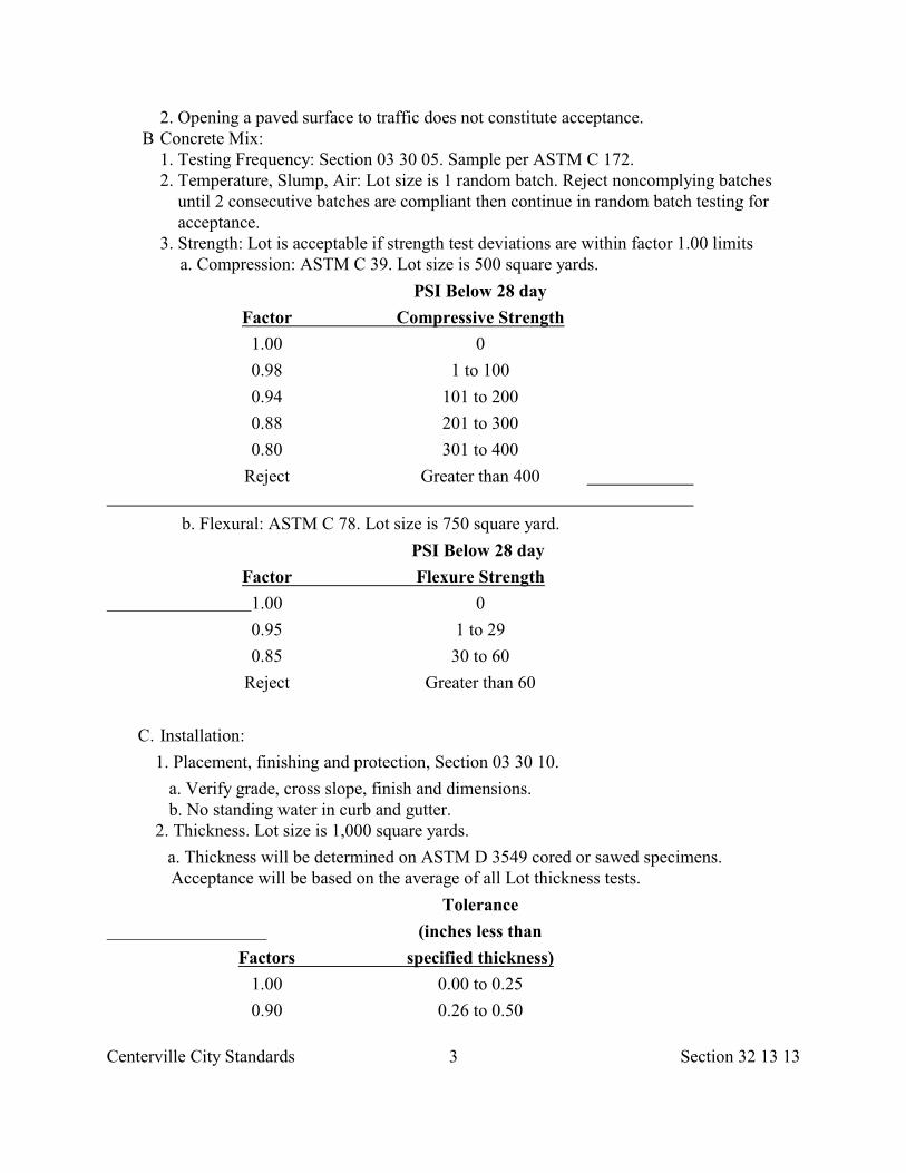
Centerville City Standards 3 Section 32 13 13
2. Opening a paved surface to traffic does not constitute acceptance. B Concrete Mix:
1. Testing Frequency: Section 03 30 05. Sample per ASTM C 172. 2. Temperature, Slump, Air: Lot size is 1 random batch. Reject noncomplying batches
until 2 consecutive batches are compliant then continue in random batch testing for acceptance.
3. Strength: Lot is acceptable if strength test deviations are within factor 1.00 limitsa. Compression: ASTM C 39. Lot size is 500 square yards.
PSI Below 28 day
Factor Compressive Strength
1.00 0
0.98 1 to 100
0.94 101 to 200
0.88 201 to 300
0.80 301 to 400
Reject Greater than 400
b. Flexural: ASTM C 78. Lot size is 750 square yard.
PSI Below 28 day
Factor Flexure Strength
1.00 0
0.95 1 to 29
0.85 30 to 60
Reject Greater than 60
C. Installation:
1. Placement, finishing and protection, Section 03 30 10.
a. Verify grade, cross slope, finish and dimensions. b. No standing water in curb and gutter.
2. Thickness. Lot size is 1,000 square yards.
a. Thickness will be determined on ASTM D 3549 cored or sawed specimens. Acceptance will be based on the average of all Lot thickness tests.
Tolerance
(inches less than
Factors specified thickness)
1.00 0.00 to 0.25
0.90 0.26 to 0.50
Centerville City Standards 4 Section 32 13 13
0.70 0.51 to 0.75
0.50 0.76 to 1.00
b. When any thickness measurement is less than specified by more than 1 inch, the actual thickness of the Pavement will be determined by taking additional cores at intervals less than 10 feet parallel to the centerline in each direction from theaffected location, until in each direction a core is found which is not deficient bymore than 1 inch. Exploratory cores for deficient thickness will not be used inaverages for price
3. Roughness: “Must grind” bumps are removed and tolerance for profile roughnessindex is not exceeded.
PART 2 PRODUCTS
2.1 CONCRETE
A. Compression Design:
1. Cast-in-place: Class 4000, Section 03 30 04. 2. Slump per accepted mix design.
B. Flexure Design.
1. Tensile Strength: 650 psi per ASTM C 78. 2. Cement Content: 6.5 bags. 3. Water Cement Ratio: 0.44 maximum by weight (prior to pozzolan exchange),
ACI 318. 4. Entrained Air: 5 to 7 percent, ASTM C 231 (pressure). 5. Slump per accepted mix design
2.2 MISCELLANEOUS MATERIALS
A. Reinforcement: Grade 60 ksi galvanized or epoxy coated steel, Section 03 20 00.
B. Hook Bolts: Steel, ASTM A 307 Grade A nuts and bolts, internally and externallythreaded.
C. Expansion Joint Filler: F1 sheet, Section 32 13 73.
D. Contraction Joint Filler (Backer Rod): Type 1 round, closed cell, ASTM D 5249.
E. Contraction Joint Sealant: HAS1, HAS4, or CAS6, Section 32 13 73.
F. Curing Compound: Liquid membrane, Section 03 39 00.
G. Bond Breaker: Wax based compound.
H. Grout: Epoxy adhesive, Section 03 61 00.
I. Evaporative Reducer: Water-based mono-molecular polymer liquid at application ratesrecommended by the manufacturer. Not to be used as a finishing aid.
Centerville City Standards 5 Section 32 13 13
PART 3 EXECUTION
3.1 PREPARATION A. General:
1. Coordinate utility location, Section 01 31 13. Contact utility companies and other agencies, for dangerous concentration of combustible, flammable, or explosive matter.
2. Lower Street Fixtures if paving machine is not capable of passing over fixtures. 3. Coat surface of Street Fixtures with oil to prevent bond with concrete Pavement. 4. Remove sand, leaves and other objectionable materials prior to placing the paving
course. 5. Notify City Engineer minimum 24 hours prior to commencement of concreting
operations. B. Trees, Plants, Ground Cover:
1. Protect trees, plants and other ground cover from damage. 2. Prune trees, Section 32 01 93 to allow equipment passage underneath. Repair tree
damage. C. Traffic Control:
1. Provide worker and public safety, Section 01 55 26. 2. Apply temporary traffic and lane marking tape or paint after placement layout has been
verified with City Engineer. D. Base Course:
1. Follow Section 31 25 00 for herbicide treatment. 2. Verify base course is placed to grade, compacted and dampened. 3. If indicated, apply prime coat, Section 32 12 13.
E. Cement Treated or Lean Concrete Base: Remove loose material from surface of cementtreated or lean concrete base course immediately before placing concrete surface course.Moisten the surface but do not place concrete over puddled water. Apply a double coat ofbond breaker prior to placing surface concrete.
3.2 FORM CONSTRUCTION
A. Section 03 11 00.
B. Check formwork for grade and alignment variance from the following tolerances:
1. Top of forms not more than 1/4 inch from true grade. 2. Vertical face on longitudinal axis not more than 1/4 inch from true line.
C. Place joint filler vertical in position, in straight lines. Secure to formwork during concreteplacement.
3.3 REINFORCEMENT PLACEMENT A. Section 03 20 00. B. Interrupt reinforcement at expansion joints.
Centerville City Standards 6 Section 32 13 13
C. Use load transfer bars on longitudinal construction and transverse constructionjoints.
D. Use smooth dowel in expansion joints.
E. Keep load transfer bars and dowels in vertical center of concrete and perpendicular tothe joint during concrete placement.
F. Position mats on bar chair supports and properly tie before any concrete is poured. Keepmats clean, free from rust, flat, and free of distortions. Straighten bends, kinks, and otherirregularities or replace units before concrete placement. Provide a minimum of 2 inchoverlap to adjacent mats.
3.4 JOINTS
A. General:
1. Review joint layout with City Engineer.2. Follow Section 32 13 73 requirements. 3. Follow joint requirements in APWA Plan No. 261.
B. Construction Joint: Construction joints (contact joints) (cold joints) are those made byplacing concrete against cured concrete.
1. The contact joint between separately laid lanes cannot deviate from a true line by more than 1/4 inch in any direction at any point.
2. Tie both sides of longitudinal and transverse construction joints together with tie bars or key-way. Before placing concrete in adjoining slab, straighten tie bars to 0.1 feet of straight position.
3. Do not cause edge slump when placing tie-bars or by over-working edge of slab. C. Contraction Joints: Contraction joints (crack control joints) are scorelines made to force
crack joint locations in concrete. Keep a minimum of 3 working power saws on theProject when concrete operations are underway. Saw all joints before uncontrolledshrinkage cracking takes place. Do not tear or ravel concrete during sawing.
1. Joint spacing measured in feet = twice the slab thickness measured in inches or a maximum of 15 feet.
2. Joint Depth = T/3. 3. Use of a mechanical control joint-void former in lieu of saw cutting or tooling is
acceptable. 4. Longitudinal Joints: Make longitudinal joints the same dimension as transverse joints. 5. Make transverse joints across width of the Pavement full length and meet curb and
gutter joints. 6. Leave forms in place until paving operations are resumed on the other side of the joint.
D. Volunteer Crack Joint:
1. If a volunteer crack joints falls within 5 feet of the location of proposed contraction joint, omit the contraction joint.
Centerville City Standards 7 Section 32 13 13
2. Rout volunteer crack joints to a 1-1/4 inch depth by 3/8 inch width. Clean and fill crack joint with backer rod and joint sealant.
3. When crack joints occur within 2 feet of expansion or construction joints, replace panel. Use saw cuts and tie-bars or dowels in cut planes.
E. Expansion Joints:
1. If a deformed rebar is used in an expansion joint, provide sleeve for movement. 2. Secure fillers to prevent movement. When butted together, do not leave voids or gaps
between filler units. 3. Set joint fillers full depth if no joint sealant is specified. 4. Recess joint fillers if backer rods and joint sealant are specified or provide a plastic
cap. F Joint Sealing: Section 32 13 73.
G If Developer chooses to open the roadway to construction or public traffic prior to finalsawing and sealing, install backer rod in the initial (green) cut to prevent entrance ofincompressibles.
3.5 CONCRETE PLACEMENT
A. Section 03 30 10.
B. At the beginning of concrete placement, test slump and air. If corrections are necessary,placement may proceed after 2 subsequent and consecutive batches pass testing.
C. Any delay in excess of 15 minutes from placing to start of finishing operations iscause for stopping placement work.
D. Do not place concrete until concrete sub base and surface course forms have beenchecked for line and grade. Moisten sub base if required to provide a uniform dampenedcondition at time of concrete placement. Do not place concrete around Manholes or otherstructures until they are at required finish elevation and cross-slope.
E. Prevent segregation of mix. Consolidate concrete along face of forms and adjacent totransverse joints with internal vibrator. Keep vibrator away from joint assemblies,reinforcement, or side forms. Use only square-faced shovels for hand-spreading andconsolidation. Consolidate with care to prevent dislocation of reinforcing, dowels, andjoint devices.
F. Do not place concrete in a longitudinal section until test specimens from the adjacentlane have attained an ASTM C 78 flexural strength (modulus of rupture) of 450 psi.
G. Deposit and spread concrete in a continuous operation between transverse joints.If interrupted for more than 1/2 hour, place a construction joint.
H. Place the concrete to the full width of the Pavement in a single constructionoperation unless indicated otherwise.
3.6 FINISHING
A. Section 03 35 00.
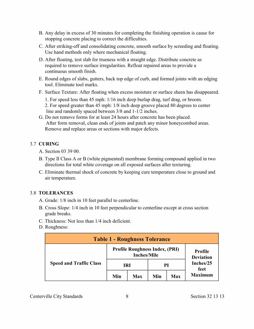
Centerville City Standards 8 Section 32 13 13
B. Any delay in excess of 30 minutes for completing the finishing operation is cause forstopping concrete placing to correct the difficulties.
C. After striking-off and consolidating concrete, smooth surface by screeding and floating.Use hand methods only where mechanical floating.
D. After floating, test slab for trueness with a straight edge. Distribute concrete asrequired to remove surface irregularities. Refloat repaired areas to provide acontinuous smooth finish.
E. Round edges of slabs, gutters, back top edge of curb, and formed joints with an edgingtool. Eliminate tool marks.
F. Surface Texture: After floating when excess moisture or surface sheen has disappeared.
1. For speed less than 45 mph: 1/16 inch deep burlap drag, turf drag, or broom. 2. For speed greater than 45 mph: 1/8 inch deep groove placed 80 degrees to center
line and randomly spaced between 3/8 and 1-1/2 inches. G. Do not remove forms for at least 24 hours after concrete has been placed.
After form removal, clean ends of joints and patch any minor honeycombed areas.Remove and replace areas or sections with major defects.
3.7 CURING
A. Section 03 39 00.
B. Type II Class A or B (white pigmented) membrane forming compound applied in twodirections for total white coverage on all exposed surfaces after texturing.
C. Eliminate thermal shock of concrete by keeping cure temperature close to ground andair temperature.
3.8 TOLERANCES
A. Grade: 1/8 inch in 10 feet parallel to centerline.
B. Cross Slope: 1/4 inch in 10 feet perpendicular to centerline except at cross sectiongrade breaks.
C. Thickness: Not less than 1/4 inch deficient. D. Roughness:
Table 1 - Roughness Tolerance
Speed and Traffic Class
Profile Roughness Index, (PRI)Inches/Mile
ProfileDeviationInches/25
feetMaximum
IRI PI
Min Max Min Max
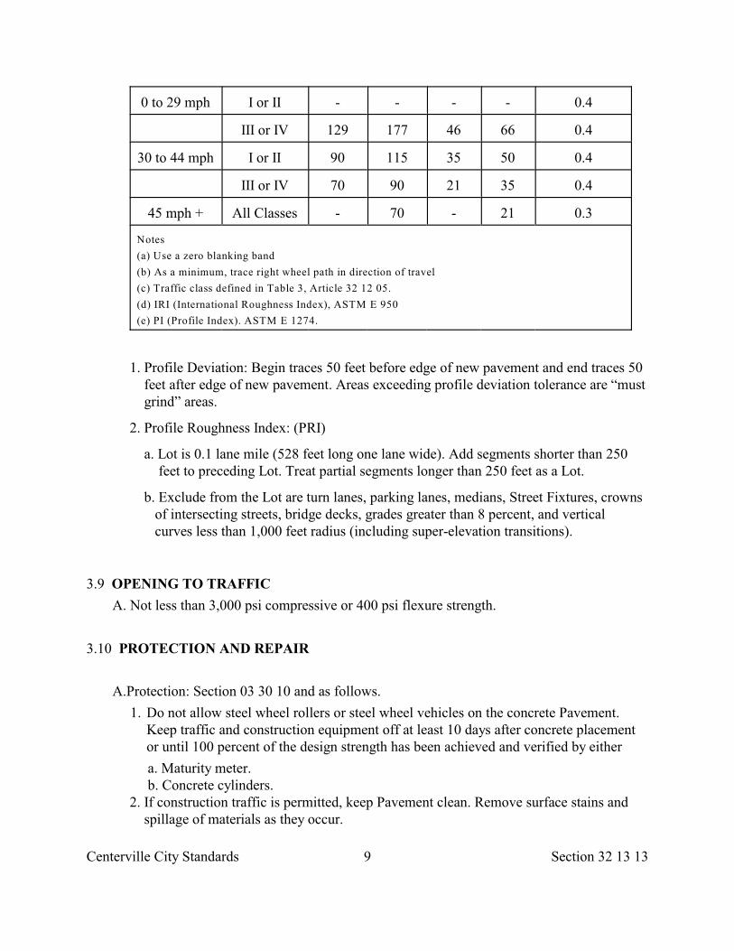
Centerville City Standards 9 Section 32 13 13
0 to 29 mph I or II - - - - 0.4
III or IV 129 177 46 66 0.4
30 to 44 mph I or II 90 115 35 50 0.4
III or IV 70 90 21 35 0.4
45 mph + All Classes - 70 - 21 0.3
Notes
(a) Use a zero blanking band
(b) As a minimum, trace right wheel path in direction of travel
(c) Traffic class defined in Table 3, Article 32 12 05.
(d) IRI (International Roughness Index), ASTM E 950
(e) PI (Profile Index). ASTM E 1274.
1. Profile Deviation: Begin traces 50 feet before edge of new pavement and end traces 50 feet after edge of new pavement. Areas exceeding profile deviation tolerance are “must grind” areas.
2. Profile Roughness Index: (PRI)
a. Lot is 0.1 lane mile (528 feet long one lane wide). Add segments shorter than 250 feet to preceding Lot. Treat partial segments longer than 250 feet as a Lot.
b. Exclude from the Lot are turn lanes, parking lanes, medians, Street Fixtures, crowns of intersecting streets, bridge decks, grades greater than 8 percent, and vertical curves less than 1,000 feet radius (including super-elevation transitions).
3.9 OPENING TO TRAFFIC
A. Not less than 3,000 psi compressive or 400 psi flexure strength.
3.10 PROTECTION AND REPAIR
A.Protection: Section 03 30 10 and as follows.
1. Do not allow steel wheel rollers or steel wheel vehicles on the concrete Pavement.Keep traffic and construction equipment off at least 10 days after concrete placementor until 100 percent of the design strength has been achieved and verified by either
a. Maturity meter. b. Concrete cylinders. 2. If construction traffic is permitted, keep Pavement clean. Remove surface stains and
spillage of materials as they occur.
Centerville City Standards 10 Section 32 13 13
3. Remove saw-cut dust immediately. Protect neighborhood, storm drains and down- stream fish habitat. B. Repair: Section 03 30 10.
1. Corrective Action for “Must Grinds”: Grinding per Section 02 41 14 is acceptable after concrete cure.
2. Corrective Action for Profile Roughness Index: Grinding is acceptable. Re-profile corrected segments to verify ride index meets tolerance.
3. Corrective Action for Cracks: Consider repair options published in Guidelines by the American Concrete Pavement Association (ACPA). Do not begin corrective work until City Engineer agrees with repair option. Drill test cores when necessary to determine magnitude. Fill holes with Portland cement concrete bonded to Pavement with epoxy adhesive.
END OF SECTION
Centerville City Standards 1 Section 32 13 73
SECTION 32 13 73
CONCRETE PAVING JOINT SEALANTS
PART 1 GENERAL
1.1 SECTION INCLUDES
A. Joints and joint sealants in horizontal traffic surfaces for concrete sidewalks, curb,gutter and Pavement slabs.
1.2 REFERENCES
A. ASTM C 920: Standard Specification for Elastomeric Joint Sealants.
B. ASTM D 545: Standard Methods of Testing Preformed Expansion Joint Fillers forConcrete Construction (Nonextruding and Resilient Types).
C. ASTM D 994: Standard Specification for Preformed Expansion Joint Filler forConcrete (Bituminous Type).
D. ASTM D 1190: Standard Specification for Concrete Joint Sealer, Hot-PouredElastic Type.
E. ASTM D 1191: Standard Method for Testing Concrete Joint Sealers.
F. ASTM D 1751: Standard Specification for Preformed Expansion Joint Filler forConcrete Paving and Structural Construction (Nonextruding and Resilient BituminousTypes).
G. ASTM D 1752: Standard Specification for Preformed Sponge Rubber and CorkExpansion Joint Fillers for Concrete Paving and Structural Construction.
H. ASTM D 1850: Standard Specification for Concrete Joint Sealer, Cold-ApplicationType.
I. ASTM D 1851: Standard Methods of Testing Concrete Joint Sealers, Cold-Application Type.
J. ASTM D 2240: Standard Test Method for Rubber Property -Durometer Hardness.
K. ASTM D 2628: Standard Specification for Preformed Polychloroprene Elastomeric JointSeals for Concrete Pavements.
L. ASTM D 3405: Standard Specification for Joint Sealants, Hot-Poured, For Concrete andAsphalt Pavements.
M. ASTM D 3406: Standard Specification for Joint Sealant, Hot-Applied, Elastomeric-Type, for Portland Cement Concrete Pavements.
N. ASTM D 3407: Standard Methods of Testing Joint Sealants,Hot-Poured, For Concrete and Asphalt Pavements.
O. ASTM D 3408: Standard Methods of Testing Joint Sealants, Hot-Poured,Elastomeric-Type, for Portland Cement Concrete Pavements.
Centerville City Standards 2 Section 32 13 73
P. ASTM D 3542: Standard Specification for Preformed Polychloroprene Elastomeric JointSeals for Bridges.
Q. ASTM D 3569: Standard Specification for Joint Sealant, Hot-Applied, Elastomeric,Jet-Fuel-Resistant-Type for Portland Cement Concrete Pavements.
R. ASTM D 3575: Standard Test Method for Flexible Cellular Materials Made fromOlefin Polymers.
S. ASTM D 3581: Standard Specification for Joint Sealant, Hot-Poured, Jet-Fuel-ResistantType, for Portland Cement Concrete and Tar-Concrete Pavements.
T. ASTM D 3582: Standard Methods for Testing Joint Sealant, Hot-Poured, Jet-Fuel-Resistant Type, for Portland Cement Concrete and Tar-Concrete Pavements.
U. ASTM D 3583: Standard Methods of Testing Joint Sealant, Hot-Applied,Elastomeric-Type, for Portland Cement Concrete Pavements, or Joint Sealant, Hot-Applied, Elastomeric, Jet-Fuel-Resistant-Type, for Portland Cement ConcretePavements.
V. ASTM D 5249: Standard Specification for Backer Material for Use with Cold-and Hot-Applied Joint Sealants in Portland-Cement and Asphalt Joints.
W. ASTM D 5893: Standard Specification for Cold Applied, Single Component,Chemically Curing Silicone Joint Sealant for Portland Cement Concrete Pavements.
X. FS SS-S-200: Sealants, Joint, Two Component, Jet-Fuel Resistant, Cold-Applied,for Portland Cement Concrete Pavement.
1.3 SYSTEM PERFORMANCES
A. Pavement joints include longitudinal and transverse expansion joints, contractionjoints, construction joints, and crack control joints.
B. Provide joint sealants that maintain watertight and airtight continuous seals.
1.4 SUBMITTALS
A. Manufacturer's certification that product was manufactured, tested and supplied persource quality control requirements specified herein, together with a report of the testresults and the date each test was completed.
B. Manufacturer's instruction for joint preparation, type of cleaning and installation.
C. Manufacturer's Product Data and Samples for each joint sealant product required.
D. Safety data sheets.
1.5 QUALITY ASSURANCE
A. Installation of joint systems are to follow manufacturer’s published directions.
B. For cold applied joint sealant installation, use installers approved by the joint sealantSupplier.
Centerville City Standards 3 Section 32 13 73
C. Obtain joint sealing materials from a single manufacturer for each different productrequired.
1.6 DELIVERY, STORAGE, AND HANDLING
A. Deliver materials to site in original unopened containers or bundles with labelsidentifying manufacturer, product name and designation, color, expiration period for use,pot life, cure time, and mixing instructions for multi-component materials.
B. Store and handle materials in compliance with manufacturer's recommendations toprevent deterioration; or damage due to moisture, high or low temperatures,contaminants, or other causes.
PART 2 PRODUCTS
2.1 GENERAL
A. Compatibility: Provide joint fillers, sealant backings, sealants, and other related materialsthat are compatible with one another and with joint substrates under conditions of serviceand application, as demonstrated by sealant manufacturer based on testing and fieldexperience.
2.2 JOINT VOID -FORMER
A. Plastic with a water stop.
B. 1/4 depth of concrete structural section
2.3 JOINT FILLER -SHEET TYPE
A. F-1: Bituminous (asphalt or tar) mastic, ASTM D 994. Formed and encased between2 layers of bituminous saturated felt or 2 layers of glass-fiber felt.
B. F-2: Cane or other cellulosic fiber, ASTM D 1751. Saturated with asphalt.
C. F-3: Granulated cork, ASTM D 1751. In an asphalt binder; encased between 2 layers ofasphalt saturated felt or 2 layers of glass-fiber felt.
D. F-4: Sponge rubber fully compressible, ASTM C 1752. With resiliency recovery rate of90 percent minimum.
E. F-5: Cork, ASTM C 1752. Impregnated and bound with asphalt, compressible withresiliency recovery rate of 90 percent if not compressed more than 50 percent oforiginal thickness.
F. F-6: Plastic foam (for cold-applied sealants only). Preformed, compressible, resilient,non-waxing, non-extruding strips of flexible, non-gassing plastic foam; non-absorbentto water and gas; 30 lb/ft density maximum, And of size and shape to control sealant
3
depth and performance.
Centerville City Standards 4 Section 32 13 73
2.4 JOINT FILLER -BACKER ROD, TAPE, POURED FILL TYPE
A. Backer material, ASTM D 5249 for cold-and hot-applied joint sealant in portland cementconcrete or asphalt Pavements joints.
1. Type 1: Round rods. 2. Type 2: Sheets or strips, laminated or skived. 3. Type 3: Poured fills which completely fill Pavement joint.
2.5 JOINT SEALANT -GENERAL
A. Color of exposed joint sealant indicated, or if not, as selected from manufacturer'sstandard colors.
2.6 JOINT SEALANT -HOT-APPLIED
A. HAS-1: Asphalt base type, ASTM D 3405.
B. HAS-2: Thermoplastic type, ASTM D 3581. Jet-fuel resistant without rubber unlessindicated otherwise.
C. HAS-3: Elastic type, ASTM D 1190.
D. HAS-4: Elastomeric type, ASTM D 3406. One component, for Portland cement concretePavements.
E. HAS-5: Elastomeric type, ASTM D 3569. One component, jet-fuel resistant, forPortland cement concrete Pavements.
2.7 JOINT SEALANT -COLD-APPLIED
A. CAS-1: Elastomeric type, ASTM C 920. Chemically curing, for vehicular or pedestrianuse, and types of construction other than highway and airfield Pavements and bridges andjoint substrates indicated; Type S or M; Grade P or NS; Class 25; Use T, NT, M and O.
1. Self leveling. 2. Shore A Hardness: 40 5 ASTM D 2240. 3. Final cure: 4 days maximum. 4. Service range: -10 to 150 deg. F.
B. CAS-2: Mastic type, ASTM D 1850. Single or multiple component; for joints having aminimum width of 1/2 inch.
C. CAS-3: Coal-tar modified urethane, FS SS-S-200. One part, jet fuel resistant; Type H.
D. CAS-4: Elastomeric preformed polychloroprene type with lubricant adhesive andindicated movement ratio.
1. For concrete Pavement seal, ASTM D 2628. 2. For concrete bridge seals, ASTM D 3542.
E CAS-5: Silicone type, ASTM D 5893. Single component, non-sag or self leveling,chemically curing sealant based on polymers of polysiloxane structure intended for usein portland cement concrete Pavements.
Centerville City Standards 5 Section 32 13 73
F. CAS-6: Asphalt base meeting ASTM D 3405.
G. CAS-7: Olefin polymer, ASTM D 3575 as follows.
1. Tensile elongation 255 percent plus or minus 20 percent, Suffix T. 560
2. Tensile strength 115 psi minimum, Suffix T 3. Density 2.9 plus or minus 3 lbs/cf, Suffix W, Method A 4. Water Absorption 0.025 lbs/sf maximum, Suffix L.
2.8 SOURCE QUALITY CONTROL
A. Preformed Expansion Joint Fillers: Nonextruding and resilient types, ASTM D 545.
B. Hot-Applied Joint Sealants:
1. Elastic type used in concrete Pavements, bridges, other structures, ASTM D 1191. 2. Bituminous type for hydraulic and asphaltic concrete Pavements, ASTM D 3407. 3. Elastomeric type for hydraulic concrete Pavement, ASTM D 3408.
C. Jet-Fuel-Resistant Joint Sealant: Hot-applied, ASTM D 3582 and ASTM D 3583.
D. Cold-Applied Mastic Joint Sealant: Cold-applied, ASTM D 1851.
PART 3 EXECUTION
3.1 PREPARATION
A. Remove oil, grease, wax, form-release-agents, curing compounds, bitumens, laitance andold chalking material by sandblast, or water blast as recommended by manufacturer ofsealant. Maximum sand blast angle, 25 degrees plus or minus 5 degrees.
B. Clean and dry with air blast. Do not contaminate air blast with oils or lubricants.
C. Remove frost and moisture in concrete joint substrates before commencingsealing.
D. Install bond breaker tape where needed or required by manufacturer'srecommendations to ensure that elastomeric sealants will perform properly.
3.2 JOINT SEALING
A. General:
1. Install sealants in uniform, continuous ribbons without gaps or air pockets, with complete bonding of joint surfaces on opposite sides.
2. Except as otherwise indicated, fill sealant rabbet flush with surface. 3. Where horizontal joints are between a horizontal surface and vertical surface, fill joint
to form a slight cove so that joint will not trap moisture and dirt. B. Depths: Saw cut joints if necessary to provide the required sealant thickness and depth.
Install sealant to depths indicated or, if not indicated, as recommended by sealantmanufacturer, but within the following general limitations measured at center (thin)
Centerville City Standards 6 Section 32 13 73
section of bead: 1. For sidewalks, Pavements, and similar joints sealed with elastomeric sealants and
subject to traffic and other abrasion and indentation exposures, fill joints to a depth equal to 75 percent of joint width, but not more than 5/8 inch deep nor less than 3/8 inch deep.
2. For normal moving joints sealed with elastomeric sealants but not subject to traffic, fill joints to a depth equal to 50 percent of joint width, but not more than 1/2 inch deep nor less than 1/4 inch deep.
3. For joints sealed with non-elastomeric sealants and caulking compounds, fill joints full depth.
C. Spillage: Do not allow poured sealant compound to overflow or spill onto adjoiningsurfaces or to migrate into voids of adjoining surfaces. Clean adjoining surfaces toeliminate evidence of spillage.
D. Heating: Do not use overheated hot-applied sealants.
E. Edges: Unless indicated otherwise, recess exposed edges of gasket and exposed jointfillers slightly behind adjoining surfaces so compressed units will not protrude fromjoints.
3.3 CURING AND CLEANING
A. Cure sealants and caulking compounds per manufacturer's instructions andrecommendations to obtain high early bond strength, internal cohesive strength andsurface durability.
B. Clean off excess sealants or sealant smears adjacent to joints as work progresses. Usemethods and cleaning materials approved by manufacturers of joint sealant and ofproducts in which joints occur.
C. Remove protective coating and oil from metals with solventrecommended by the sealant manufacturer.
3.4 PROTECTION
A. Protect joint sealant during and after curing period from contact with contaminatingsubstances or from damage resulting from deterioration or damage at time of SubstantialCompletion.
B. If damage or deterioration occurs, cut out and remove damaged or deteriorated jointsealant immediately and reseal joints with new materials to produce joint sealerinstallations with repaired areas indistinguishable from original work.
END OF SECTION
Centerville City Standards 1 Section 32 14 13
SECTION 32 14 13
PRECAST CONCRETE UNIT PAVING
PART 1 GENERAL
1.1 SECTION INCLUDES
A. Mortarless interlocking concrete pavers for sidewalks, roadways and similar pavings.
1.2 REFERENCES
A. ASTM C 33: Standard Specification for Concrete Aggregates.
B. ASTM C 67: Standard Method of Sampling and Testing Brick and Structural Clay Tile.
C. ASTM C 136: Standard Method for Sieve Analysis for Fine and Coarse Aggregates.
D. ASTM C 140: Standard Method of Sampling and Testing Concrete Masonry Units.
E. ASTM C 144: Standard Specification for Aggregate for Masonry Mortar.
F. ASTM C 150: Standard Specification for Portland Cement.
G. ASTM C 936: Standard Specification for Solid Interlocking Concrete Paving Units.
H. ASTM C 979: Coloring Agents for Concrete.
I. ASTM D 1557: Standard Test Methods for Moisture-Density Relations of Soils and Soil-Aggregate Mixtures, Using a 10 lb (4.54-kg) Rammer and an 19-In. (457-mm) Drop.
J. ASTM D 3786: Standard Test Method for Hydraulic Bursting Strength of Knitted Goodsand Nonwoven Fabrics Diaphragm Bursting Strength Tester Method.
K. ASTM D 4751: Standard Test Method for Determining Apparent Opening Size for aGeotextile.
L. ICPI: Interlocking Concrete Paver Institute.
1.3 SUBMITTALS
A. Data sheets for
1. Bedding sand gradation. 2. Joint sand gradation. 3. Joint sand stabilizer. 4. Paver strength and absorption. Test results not older than 365 days.
B. Certification that paver unit complies with ASTM C 936.
1.4 QUALITY ASSURANCE
A. Installer must have successfully completed at least 3 unit paver applications of similarsize and scope and will assign mechanics from these earlier applications to the Project,of which one will serve as lead mechanic.
Centerville City Standards 2 Section 32 14 13
B. Installer will have on site during the course of paving personnel who is knowledgeableof ICPI technical bulletins.
1.5 PRODUCT HANDLING
A. Protect unit pavers against soilage. Protect sand against intermixture with earth orother types of materials.
B. Do not build on frozen Subgrade or setting beds.
C. Remove damaged pavers.
PART 2 PRODUCTS
2.1 CONCRETE PAVERS
A. Solid interlocking units per ASTM C 936 with spacer bars.
1. Cement: ASTM C 150 hydraulic cement. 2. Aggregates: ASTM C 33 sand and natural aggregates (washed and graded with no
expanded shale or light weight aggregates). 3. Average Compressive Strength: Greater than 8,000 psi with no individual unit test less
than 7,200 psi. 4. Average Absorption: Less than 5 percent with no individual unit greater than 7 percent,
ASTM C 140. 5. Freeze-Thaw: Resistance to 50 cycles, ASTM C 67. 6. Efflorescence Prevention: Admixture per recommendation of manufacturer.
B. Shape: 200 mm x 100 mm unless specified elsewhere.
C. Thickness:
1. Sidewalks: 60 mm. 2. Roadways: 80 mm. 3. Crosswalks: 80 mm. 4. Driveway Approaches: 80 mm.
D. Color: Reddish brown using an inorganic mineral oxide.
2.2 BEDDING AND JOINT SAND
A. Clean, non-plastic, naturally occurring silica sand conforming to ASTM C 33 or ASTM C144, with no more than 5 percent acid soluble material.
B. Gradation must not vary from the high limit on one sieve to the low limit on the next. Graded by dry weight to pass sieves per ASTM C 136 as follows.
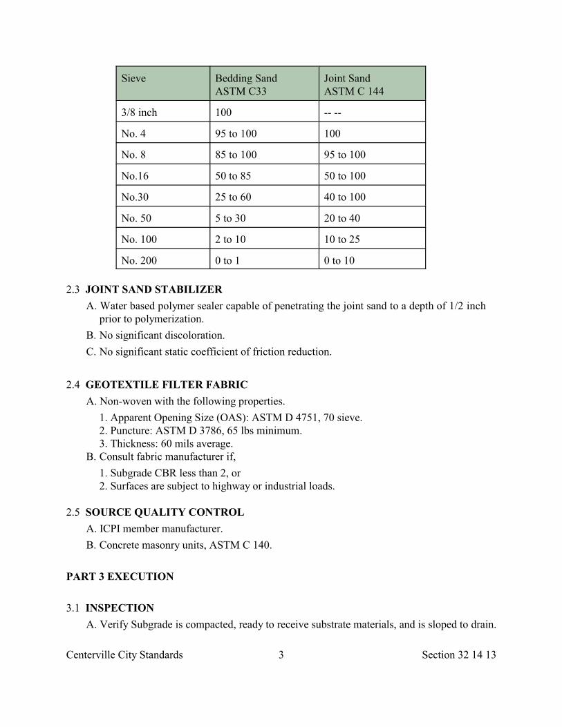
Centerville City Standards 3 Section 32 14 13
Sieve Bedding Sand ASTM C33
Joint Sand ASTM C 144
3/8 inch 100 -- --
No. 4 95 to 100 100
No. 8 85 to 100 95 to 100
No.16 50 to 85 50 to 100
No.30 25 to 60 40 to 100
No. 50 5 to 30 20 to 40
No. 100 2 to 10 10 to 25
No. 200 0 to 1 0 to 10
2.3 JOINT SAND STABILIZER
A. Water based polymer sealer capable of penetrating the joint sand to a depth of 1/2 inchprior to polymerization.
B. No significant discoloration.
C. No significant static coefficient of friction reduction.
2.4 GEOTEXTILE FILTER FABRIC
A. Non-woven with the following properties.
1. Apparent Opening Size (OAS): ASTM D 4751, 70 sieve. 2. Puncture: ASTM D 3786, 65 lbs minimum. 3. Thickness: 60 mils average.
B. Consult fabric manufacturer if,
1. Subgrade CBR less than 2, or 2. Surfaces are subject to highway or industrial loads.
2.5 SOURCE QUALITY CONTROL
A. ICPI member manufacturer.
B. Concrete masonry units, ASTM C 140.
PART 3 EXECUTION
3.1 INSPECTION
A. Verify Subgrade is compacted, ready to receive substrate materials, and is sloped to drain.
Centerville City Standards 4 Section 32 14 13
3.2 PREPARATION
A. Layout: Check final elevations and patterns for conformance to Drawings.
B. Installation over soil base. 1. Place specified base course over compacted Subgrade at specified thickness. 2. Compact to greater than 95 percent ASTM D 1557.
3. Soil base surface tolerance is 3/8 inch in 10 feet. C. Installation over concrete base.
1. Fill drainage holes in concrete base with bedding sand. 2. Cover filled drainage holes with geotextile.
3.3 INSTALLATION A. Bedding Sand:
1. Place and screed allowing for paver height and compaction. 2. After screeding, do not disturb or compact. Fill screed rails voids with loose sand. 3. Remove all compressions in the bedding sand. 4. Remove from bedding sand any concrete dust or waste from the paver cutting
operation B. Cutting Pavers:
1. Point up joints to provide a neat, uniform appearance. 2. Minimum cut length is 3/4 paver, or 1/2 paver providing adjacent paver is also reduced
no more than 1/2 its original length. 3. Cut vertical faces with masonry saw. 4. No chipping or breaking for shaping. 5. No modification of top or bottom face of paver.
C. Pavers:
1. Do not install paver over saturated or dry sand. Sand should be damp. 2. Paver surface to be 1/8 to 3/16 inch above grade or edge restraints after compaction. 3. Keep paver lines straight, true, and square. 4. Use a low amplitude, high frequency plate vibrator capable of at least 5,000 lbf at a
frequency of 75 hz to 10 hz. 5. Do not vibrate within 6 feet of an unrestrained edge of pavers.
D. Joint Width:
1. 1.5mm–4mm. 2. Maximum 50 percent between 2mm–3mm and 10 percent between 3mm–4mm in any
3 feet square area. E. Joint Sand and Stabilizer:
1. After setting pavers, sweep joint sand into joints and vibrate again until joints are full. 2. Bedding sand may be used for joint sand, however, extra effort in sweeping and
compacting the pavers may be required in order to completely fill the joints. 3. After final vibration remove excess sand and debris.
4. Apply joint sand stabilizer within 1 week of installing joint sand.
Centerville City Standards 5 Section 32 14 13
3.4 TOLERANCES A. Lippage: 1/16 inch maximum elevation difference unit to unit. B. Cross Slope: 1/8 inch in 10 feet. C. Longitudinal:.
1. Sidewalks: 1/8 inch in 10 feet. 2. Roadway: a. 1/8 inch in 10 feet parallel to centerline. b. 1/4 inch in 10 feet perpendicular to centerline except at cross section grade breaks.
3.5 PROTECTION AND REPAIR
A. Provide final protection and maintain conditions in a manner acceptable to installer.
B. Repair:
1. Remove and replace non-matching pavers or pavers which are chipped, broken, stained or otherwise damaged. Fill joints with joint sand and compact with plate compactor.
2. Remove excess sand.
END OF SECTION
Centerville City Standards 1 Section 32 14 16
SECTION 32 14 16
BRICK UNIT PAVING
PART 1 GENERAL
1.1 SECTION INCLUDES A. Handling and installation procedures for paving brick. B. Material requirements and tolerances.
1.2 REFERENCES A. ANSI: American National Standards Institute. B. ASTM C 33: Standard Specification for Concrete Aggregates.
C. ASTM C 144: Standard Specification for Aggregate for Masonry Mortar.
D. ASTM C 150: Standard Specification for Portland Cement.
E. ASTM C 207: Standard Specification for Hydrated Lime for Masonry Purposes.
F. ASTM C 902: Standard Specification for Pedestrian and Light Traffic Paving Brick.
G. BIA: Brick Institute of America.
1.3 SUBMITTALS
A. Test Reports: Submit control testing reports as requested verifying compliance withspecified standards.
B. Brick Samples: Prior to commencing work, obtain approval of representativeSamples of the brick specified.
1.4 PRODUCT HANDLING
A. Handle and store paving brick in a manner to avoid chipping, breakage, intrusion offoreign matter, and staining.
B. Handle, store, mix and apply proprietary setting and grouting materials in strictcompliance with the manufacturer's instructions.
C. Take precautions to protect the mortar and grout admixtures from freezing or fromexcessive heat.
PART 2 PRODUCTS
2.1 PAVING BRICK
A. ASTM C 902 classification Type SX (freeze resistant), Traffic Type 1 (extensiveabrasion), application PX (without mortar joints) unless indicated otherwise.
Centerville City Standards 2 Section 32 14 16
1. Nominal Size: 3-5/8 inches x 7-5/8 inches x 2 inches for roadway or Driveway areas, 3-5/8 inches x 7-5/8 inches x 1 inch for sidewalk areas.
2. Color: Reddish brown if not elsewhere specified. 3. Friction Test: 0.5 minimum for wet leather and wet brick.
2.2 MORTAR AND GROUT
A. Mixture of water, ASTM C 150 type I Portland cement, ASTM C 207 type S lime, ASTMC 144 mason's sand, ASTM C 33 concrete sand to provide the following.
1. Compressive Strength: Thick bed mortar, 3,000 psi minimum. 2. Compressive Strength: Thin bed, bonding, grouting mortars, 5,000 psi minimum. 3. Tensile Strength: Thin bed, bonding, grouting mortars, 500 psi minimum. 4. Bond Strength: Thin bed, bonding, grouting mortars, 500 psi minimum. 5. Water Absorption: 4.0 percent maximum. 6. Ozone Resistance: 200 hours at 200 ppm. No loss of strength. 7. Smoke Contribution Factor: 0 8. Flame Contribution Factor: 0
B. Resistant to urine, dilute acid, dilute alkali, sugar, brine, and food waste products.
C. Additives compatible from one manufacturer, non-toxic, non-flammable, and non-hazardousduring storage, mixing, application, and when cured. The addition of water or other materials to dilute the mortar additive on the job site will not be permitted.
2.3 REINFORCING MESH
A. 6 x 6 x 10 gage galvanized welded wire mesh, Section 03 20 00.
2.4 WATER REPELLANT
A. Penetrating compound, Section 07 19 00.
2.5 JOINT SEALING COMPOUND
A. CAS1 polyurethane, Section 32 13 73 unless indicated otherwise.
PART 3 EXECUTION
3.1 INSPECTION
A. Inspect surfaces scheduled to receive brick paving for:
1. Defects that will affect the execution and quality of the Work. 2. Deviations beyond allowable tolerances over the substrate.
B. Correct unsatisfactory conditions.
Centerville City Standards 3 Section 32 14 16
3.2 PREPARATION
A. Clean surfaces as required to remove materials which will affect installation.
B. Place concrete base to nominal finish grade, minus paving brick thickness andsetting bed mortar.
C. Wet cure concrete base. Remove curing compounds by sandblast prior to placingsetting bed mortar.
3.3 INSTALLATION
A. Install per ANSI and BIA recommendations.
B. Cut units with powered masonry saw.
C. Lay units out so that fields or patterns center in areas.
D. Lay units out to minimize pieces smaller than 1/2 brick.
E. Set units into setting bed while mortar is still plastic or set in thin set mortar overprepared setting bed.
F. Tap each unit firmly into place to assure full adhesion.
G. Set units with nominal 3/8 inch joints between units.
H. Force grout between units to fill joints completely.
I. Remove surplus grout and leave faces clean.
J. Flood brick paving to determine any areas of standing water. Remove and replace anyarea where ponding is found to stand more than 3/8 inch deep.
K. Provide sealant joints where brick abuts vertical surfaces, around penetrations, andover expansion or control joints where indicated.
L. Apply surface sealer per manufacturer's recommendation.
3.4 TOLERANCES
A. For finish surface of paving, do not exceed 1/16 inch unit to unit offset to flush, and atolerance of 1/8 inch in 2 feet and 1/4 inch in 10 feet from level or slope indicated.
3.5 PROTECTION
A. Protect installed pavers from damage.
B. Do not allow vehicular traffic on brick paving for 14 days or until the mortar andunderlying concrete has reached a strength of 3,000 psi.
C. Provide alternate access to adjacent properties.
3.6 CLEANING
A. Remove protective coverings.
Centerville City Standards 4 Section 32 14 16
B. Clean entire surface with cleaning compound.
C. Protect adjacent surfaces from damage due to cleaning operations.
END OF SECTION
Centerville City Standards 1 Section 32 16 13
SECTION 32 16 13
DRIVEWAY, SIDEWALK, CURB, GUTTER
PART 1 GENERAL
1.1 SECTION INCLUDES
A. Concrete flatwork such as but not limited to waterways, waterway transition structures,sidewalks, curbs, gutters, driveway approaches.
1.2 REFERENCES
A. American Public Works Association (Utah Chapter).
1. Plan 205: Curb and Gutter. 2. Plan 209: Curbs. 3. Plan 211: Waterway. 4. Plan 213: Waterway Transition Structure. 5. Plan 215: Dip Driveway Approach. 6. Plan 216: Mountable curb driveway approach. 7. Plan 221: Flare Driveway Approach. 8. Plan 225: Open Driveway Approach. 9. Plan 229: Pipe Driveway Approach. 10. Plan 231: Concrete Sidewalk.
B. ASTM A 36: Standard Specifications for Structural Steel.
C. ASTM C 39. Standard Test Method for Compressive Strength of CylindricalConcrete Specimens.
D. ASTM C 172: Standard Method of Sampling Freshly Mixed Concrete.
1.3 DEFINITIONS
A. Driveway: A paved or unpaved vehicular thoroughfare outside of, but connected to apublic road right-of-way or highway right-of-way.
B. Driveway Approach: (1) A vehicular thoroughfare connecting a public road or highway toa driveway. (2) A concrete structure composed of sidewalk, apron and any curb and gutterabutting the apron. When an apron is built as a bridge over curb and gutter, the bridge isincluded in this definition.
1.4 SUBMITTALS
A. Traffic control plan, Section 01 55 26.
B. Concrete mix design, Section 03 30 04.
C. Batch ticket, Section 03 30 10.
Centerville City Standards 2 Section 32 16 13
D. Quality Control Inspections and Testing Report: Upon City Engineer’s request, submit areport describing source and field quality control activities and test results performed byDeveloper and Developer’s Suppliers.
1.5 NOTICE
A. Send written notice to residents and businesses within affected area at least 3 daysbefore work starts.
B. Indicate when concrete work will take place and when driveway approach can beused.
C. Warn of potential vehicle tow away and other construction issues affectingneighborhood.
D. Should work not occur on specified day, send a new notice.
1.6 ACCEPTANCE
A. General:
1. Acceptance is by Lot. One Lot is one day’s production.
B. Concrete Mix:
1. Testing Frequency: Section 03 30 05. Sample per ASTM C 172. 2. Temperature, Slump, Air: Lot size is 1 random batch. Reject noncomplying batches
until 2 consecutive batches are compliant then proceed in random batch testing foracceptance.
3. Strength: ASTM C 39. Lot size is 50 cubic yards.
PSI Below 28 dayFactor Compressive Strength
0.98 1 to 1000.94 101 to 2000.88 201 to 3000.80 301 to 400
Reject Greater than 400
C. Placement, finishing and protection, Section 03 30 10 1. Verify line, grade, cross slope and finish. 2. No standing water in curb and gutter.
PART 2 PRODUCTS
2.1 MATERIALS
A. Concrete Mix.:
Centerville City Standards 3 Section 32 16 13
1 Cast-in-place: Class 4000, Section 03 30 04. 2. Maximum slump per mix design.
B. Reinforcement: Grade 60 ksi galvanized or epoxy coated steel per Section 03 20 00.
C. Expansion Joint Filler: F1 sheet 1/2 inch thick per Section 32 13 73.
D. Contraction Joint Filler (Backer Rod): Closed cell, Type 1 round Section 32 13 73.
E. Contraction Joint Sealer: HAS1 or HAS4 hot applied per Section 32 13 73.
F. Curing Compound: Membrane forming compound per Section 03 39 00.
G. Plate Steel: ASTM A 36 galvanized.
PART 3 EXECUTION
3.1 CONSTRUCTION EQUIPMENT
A. Slip Form Machines.
1. Placement must produce required cross-section, lines, grades, finish, and jointing asspecified for formed concrete.
2. If results are not acceptable, remove and replace work with formed concrete.
3.2 PREPARATION
A. Control pedestrian and vehicular traffic, Section 01 55 26.
B. Examine surfaces scheduled to receive concrete formwork for defects.
C. Do not start work until defects are corrected.
D. Check slopes on each side of the work to ensure drainage. Failure to check and verifywill result in Developer repairing any drainage deficiencies.
3.3 LAYOUT
A. Curb, Gutter, Curb and Gutter (See Centerville City Standard Details).
1. Line: Less than 1/2 inch variance in 10 feet and not more than 1 inch from true line atany location.
2. Grade: Not more than 1/4 inch variance in 10 feet. Flood curb and gutter with waterafter final cure has been reached. Remove and replace any area where ponding isfound.
B. Sidewalk: (See Centerville City Standard Details).
1. Cross slope 2 percent. 2. Landing slope 2 percent maximum in any direction. 3. Ramp slope, Section 32 16 14.
C. Driveway Approaches: (See Centerville City Standard Details).
Centerville City Standards 4 Section 32 16 13
3.4 CONCRETE PLACEMENT
A. Section 03 30 10. B. Make sure base course is uniformly damp at time of concrete placement.
C. Obtain City Engineer's review of base course and forms before placing concrete.
D. Do not use methods that segregate the mix.
E. Place concrete so time between end of placement and beginning of finishing is lessthan 15 minutes.
F. Consolidate concrete with vibrator or other acceptable method. Do not use mechanicalvibrators. Prevent dislocation of inserts.
3.5 CONTRACTION JOINTS
A. Geometrics:
1. Tooled Joints (Score Lines): • Depth = T/4. T is the depth of the concrete slab in inches. • Top radius = 1/2 inch.
2. Saw Cut Joints: Saw joints before uncontrolled shrinkage cracking occurs. Do not tearor ravel concrete during sawing.
3. Template Joints: 1/8 to 3/16 inch wide 1/4-depth of slab. B. Sidewalks.
1. At intervals equal to the width of the sidewalk and transverse to the line of walk. 2. Radial at curbs and walk returns. 3. Place longitudinal joints in walks when width of walk in feet is greater than 2 times the
walk thickness in inches. (e.g. maximum width of a 4 inch thick walk beforeplacement of a longitudinal contraction joint is 8 feet). Make longitudinal jointsparallel to, or concentric with, the lines of the walk.
4. In walk returns make 1 joint radially midway between the beginning of curb returns(BCR) and end of curb returns (ECR). Match longitudinal and traverse joints with theadjacent walks.
C. Curb, Gutter, Waterway.
1. Place joints at intervals not exceeding 12 feet. 2. At curb radius and walk returns make the joints radial. 3. Where integral curb and gutter is adjacent to concrete Pavement, align the joints with
the Pavement joints where practical. D. Additional Contraction Joint Requirements: Section 32 13 73.
3.6 EXPANSION JOINTS
A. Geometrics: 1/2 inch wide full depth filler that is flush with concrete surface. Do notplace seal over top of filler
Centerville City Standards 5 Section 32 16 13
B. Sidewalks, Sidewalk Ramps.
1. Place expansion joints to separate sidewalk from utility poles, hydrants, Manholeframes, buildings and abutting sidewalks.
2. Place expansion joints between the sidewalk and the back of curb returns and betweenthe sidewalk and sidewalk ramps.
3. Do not place expansion joints in sidewalk ramp surfaces. 4. Expansion joints are not required when using slip form method to place concrete
except where sidewalk changes direction or where it joins foundation walls orstructures.
C. Curb, Gutter, Waterway.
1. Do not place longitudinal joints in drain gutter flow-lines. 2. Where drain gutter transitions extend beyond the curb return, place expansion joints at
the ends of the drain gutter transition. 3. Place expansion joints at beginning of curb radius (BCR) and end of curb radius
(ECR). D. Slip Form Work: Expansion joints are not required except at BCR or ECR.
E. Driveway Approach: Do not place expansion joints in curb returns.
F. Street Intersection Corner: Place expansion joints at BCR and ECR.
G. Additional Expansion Joint Requirements: Section 32 13 73.
3.7 FINISH
A. Section 03 35 00.
B. Round edges exposed to public view to a 1/2 inch radius.
C. Apply broom finish longitudinal to curb and gutter flowline.
D. Apply broom finish transverse to sidewalk centerline as follows.
1. Fine hair finish where grades are less than 6 percent. 2. Rough hair finish where grades exceed 6 percent.
E. Remove form marks or irregularities from finish surfaces.
3.8 CURING
A. Section 03 39 00.
B. Type ID Class A (clear with fugitive dye) membrane forming compound. Applytotal coverage in 2 directions after texturing.
C. Eliminate thermal shock of concrete by keeping cure temperature even throughoutextent and depth of concrete slab.
3.9 PROTECTION AND REPAIRS
Centerville City Standards 6 Section 32 16 13
A. Protection: Section 03 30 10.
1. Protect concrete work from deicing chemicals during the 28 day cure period. 2. Immediately after placement, protect concrete from graffiti or other types of
mechanical injury.
B. Repair: Section 03 30 10. 1. Correct all humps or depressions. 2. Secure City Engineer’s acceptance of method of correction.
END OF SECTION
Centerville City Standards 1 Section 32 16 14
SECTION 32 16 14
CURB RAMP
PART 1 GENERAL
1.1 SECTION INCLUDES A. Concrete flatwork for curb cut assemblies.
1.2 REFERENCES A. American Public Works Association (Utah Chapter).
1. Plan 235: Corner Curb Cut Assembly. 2. Plan 236: Tangent Curb Cut Assembly. 3. Plan 237: Islands and Median. 4. Plan 238: Detectable Warning Surface.
B. Work Zone Traffic Control Guide: Publication of the Utah LTAP Center.
1.3 DEFINITIONS
A. Clear Space: A 4 feet minimum by 4 feet minimum surface located within the width ofthe crosswalk and adjacent to a curb cut.
B. Cross Slope: Grade perpendicular to the direction of pedestrian travel usually expressedin percent.
C. Running Slope: Grade parallel to the direction of pedestrian travel usually expressedin percent.
D. Ramp: A flat surface with a maximum Running Slope of 1:12 (8.33 percent) and amaximum Cross Slope of 1:48 (2 percent) with sides perpendicular to its ends andends parallel to each other.
E. Curb Ramp: A Ramp that cuts through a curb.
F. Detectable Warning Surface: A surface of truncated domes aligned in a square or radial gridpattern.
G. Cross Width: Distance perpendicular to the direction of pedestrian travel usually expressedin lineal measure.
H. Running Width: Distance parallel to the direction of pedestrian travel usually expressedin lineal measure.
1.4 SUBMITTALS
A. Traffic control plan, Section 01 55 26.
B. Concrete mix design, Section 03 30 04.
Centerville City Standards 2 Section 32 16 14
C. Batch ticket, Section 03 30 10.
D. Detectable Warning Surface product data sheet.
1.5 ACCEPTANCE A. Clear Space: Running Slope. B. Flow-line: No standing water, no trip hazard. C. Detectable Warning Surface:
1. Color contrast, dome geometry, joints between units. 2. Cross Width, Running Width.
D. Curb Cut: Cross Width (appropriate to number of crosswalks served). E. Landing: Running Slope, Cross Slope, dimensions. F. Ramp: Running Slope, Cross Slope, Cross Width, transition ends.
PART 2 PRODUCTS
2.1 MATERIALS A. Cast-in-place Concrete: Class 4000, Section 03 30 04. B. Pavers:
1. Concrete, Section 32 14 13. 2. Brick, Section 32 14 16.
C. Other Materials: City Engineer’s choice.
PART 3 EXECUTION
3.1 PREPARATION A. Refer to Work Zone Traffic Control Guide.
3.2 TRAFFIC CONTROL A. Provide safe passage for pedestrians and vehicles. B. Assist visually impaired and wheel chair users. C. Provide continuous access to fire hydrants. D. Keep passage ways free of construction materials, trash and debris. E. Remove graffiti immediately.
3.3 LAYOUT A. Curb Cut excluding flare or curb radius measurement):
1. Cross Width at Curb Ramp. a. 4 feet minimum serving one crosswalk. b. 8 feet minimum serving two or more crosswalks.
Centerville City Standards 3 Section 32 16 14
2. Cross Slope at Curb Ramp: 2 percent maximum. B. Detectable Warning Surface:
1. Running Length: 2 feet minimum. 2. Cross Width: a. 4 feet minimum serving one crosswalk. b. 8 feet minimum serving two or more crosswalk. 3. Joint Between Units: 3/16 inch maximum or manufacturer’s recommendation
C. Landing: Determine landing position and elevation so ramps that slope to and from thelanding meet ramp slope requirements.
D. Ramp:
1. Do not exceed maximum slope or 15 feet length. 2. It may be necessary to include a transition zone between a curb cut and ramp.
E. Curb Wall: Set top of curb wall equal to elevation of extended lateral lines of sidewalk.
3.4 INSTALLATION
A. Pour concrete, Section 03 30 10.
B. Install Detectable Warning Surface full length and full width across the pedestrian accessroute.
END OF SECTION
Centerville City Standards 1 Section 32 17 23
SECTION 32 17 23
PAVEMENT MARKINGS
PART 1 GENERAL
1.1 SECTION INCLUDES A. Paints for Pavement striping. B. Words and other markings in paint or plastic film. C. One or two-way prismatic reflectors for Pavement marking.
1.2 REFERENCES
A. AASHTO M 237: Standard Specification and Recommended Practice for Epoxy ResinAdhesive for Bonding Traffic Markers to Hardened Concrete.
B. AASHTO M 247: Standard Specification for Glass Beads Used in Traffic Paint.
C. AASHTO M 248: Standard Specification for Ready-Mixed White and Yellow TrafficPaints.
D. AASHTO M 249: Standard Specification for White and Yellow ReflectiveThermoplastic Striping Material (Solid Form).
E. ASTM D 638: Standard Test Method for Tensile Properties of Plastics.
F. ASTM E 303: Standard Method for Measuring Surface Frictional Properties Usingthe British Pendulum Tester.
G. FS L-S-300: Sheeting and Tape, Reflective: Nonexposed Lens.
H. Federal Standard 141: Paint, Varnish, Lacquer and Related Materials, Methods ofInspection, Sampling, and Testing.
I. Federal Standard 370: Instrumental Photometric Measurements of RetroflectiveMaterials and Retroreflective Devices.
J. MUTCD: Manual on Uniform Traffic Control Devices for Streets and Highways.
1.3 SUBMITTALS
A. Specifications of primer to be used for tape applications.
B. Manufacturer's affidavit certifying paint products meet or exceed materialrequirements of this section.
C. Sample of prismatic reflector to be used along with manufacturer's statement of thereflector's minimum reflective area and specific intensity at the 0.2 degreeobservation angle.
D. Manufacturer's recommendation for type of epoxy to be used when installingprismatic reflectors and markers.
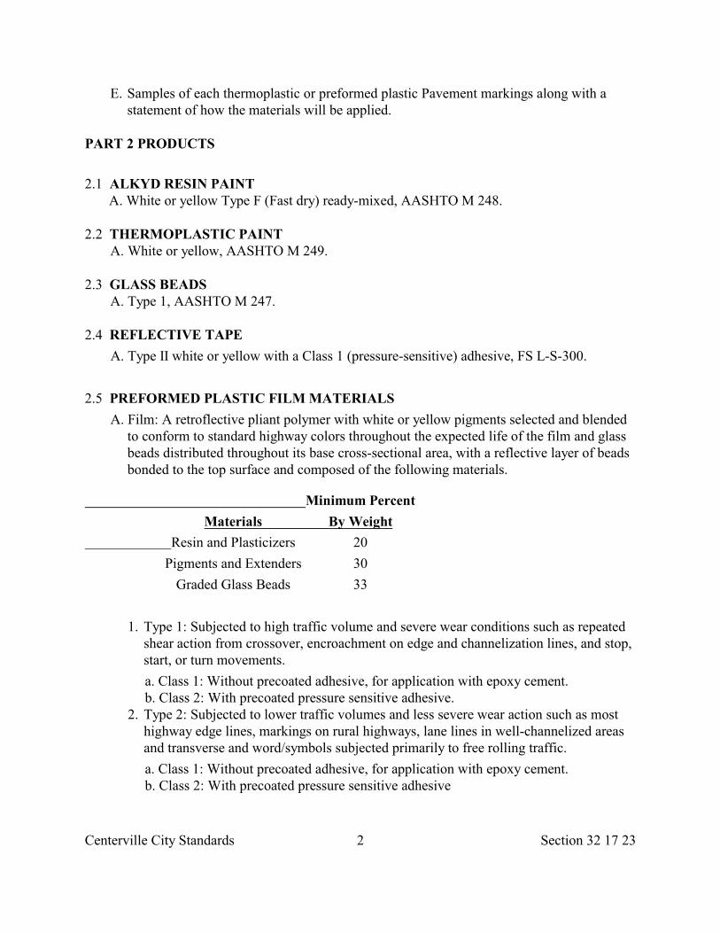
Centerville City Standards 2 Section 32 17 23
E. Samples of each thermoplastic or preformed plastic Pavement markings along with astatement of how the materials will be applied.
PART 2 PRODUCTS
2.1 ALKYD RESIN PAINT A. White or yellow Type F (Fast dry) ready-mixed, AASHTO M 248.
2.2 THERMOPLASTIC PAINT A. White or yellow, AASHTO M 249.
2.3 GLASS BEADS A. Type 1, AASHTO M 247.
2.4 REFLECTIVE TAPE
A. Type II white or yellow with a Class 1 (pressure-sensitive) adhesive, FS L-S-300.
2.5 PREFORMED PLASTIC FILM MATERIALS
A. Film: A retroflective pliant polymer with white or yellow pigments selected and blendedto conform to standard highway colors throughout the expected life of the film and glassbeads distributed throughout its base cross-sectional area, with a reflective layer of beadsbonded to the top surface and composed of the following materials.
Minimum Percent
Materials By Weight
Resin and Plasticizers 20
Pigments and Extenders 30
Graded Glass Beads 33
1. Type 1: Subjected to high traffic volume and severe wear conditions such as repeatedshear action from crossover, encroachment on edge and channelization lines, and stop,start, or turn movements.
a. Class 1: Without precoated adhesive, for application with epoxy cement. b. Class 2: With precoated pressure sensitive adhesive. 2. Type 2: Subjected to lower traffic volumes and less severe wear action such as most
highway edge lines, markings on rural highways, lane lines in well-channelized areasand transverse and word/symbols subjected primarily to free rolling traffic.
a. Class 1: Without precoated adhesive, for application with epoxy cement. b. Class 2: With precoated pressure sensitive adhesive
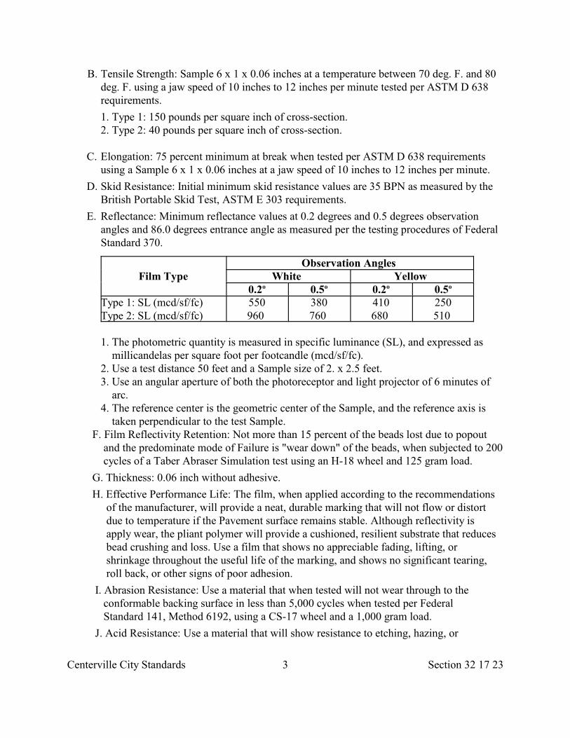
Centerville City Standards 3 Section 32 17 23
B. Tensile Strength: Sample 6 x 1 x 0.06 inches at a temperature between 70 deg. F. and 80deg. F. using a jaw speed of 10 inches to 12 inches per minute tested per ASTM D 638requirements.
1. Type 1: 150 pounds per square inch of cross-section. 2. Type 2: 40 pounds per square inch of cross-section.
C. Elongation: 75 percent minimum at break when tested per ASTM D 638 requirements using a Sample 6 x 1 x 0.06 inches at a jaw speed of 10 inches to 12 inches per minute.
D. Skid Resistance: Initial minimum skid resistance values are 35 BPN as measured by the British Portable Skid Test, ASTM E 303 requirements.
E. Reflectance: Minimum reflectance values at 0.2 degrees and 0.5 degrees observation angles and 86.0 degrees entrance angle as measured per the testing procedures of Federal Standard 370.
Film TypeObservation Angles
White Yellow 0.2 0.5 0.2 0.5o o o o
Type 1: SL (mcd/sf/fc)Type 2: SL (mcd/sf/fc)
550960
380760
410680
250510
1. The photometric quantity is measured in specific luminance (SL), and expressed as millicandelas per square foot per footcandle (mcd/sf/fc).
2. Use a test distance 50 feet and a Sample size of 2. x 2.5 feet. 3. Use an angular aperture of both the photoreceptor and light projector of 6 minutes of
arc. 4. The reference center is the geometric center of the Sample, and the reference axis is
taken perpendicular to the test Sample. F. Film Reflectivity Retention: Not more than 15 percent of the beads lost due to popout and the predominate mode of Failure is "wear down" of the beads, when subjected to 200 cycles of a Taber Abraser Simulation test using an H-18 wheel and 125 gram load.
G. Thickness: 0.06 inch without adhesive.
H. Effective Performance Life: The film, when applied according to the recommendations of the manufacturer, will provide a neat, durable marking that will not flow or distort due to temperature if the Pavement surface remains stable. Although reflectivity is apply wear, the pliant polymer will provide a cushioned, resilient substrate that reduces bead crushing and loss. Use a film that shows no appreciable fading, lifting, or shrinkage throughout the useful life of the marking, and shows no significant tearing, roll back, or other signs of poor adhesion.
I. Abrasion Resistance: Use a material that when tested will not wear through to the conformable backing surface in less than 5,000 cycles when tested per Federal Standard 141, Method 6192, using a CS-17 wheel and a 1,000 gram load.
J. Acid Resistance: Use a material that will show resistance to etching, hazing, or
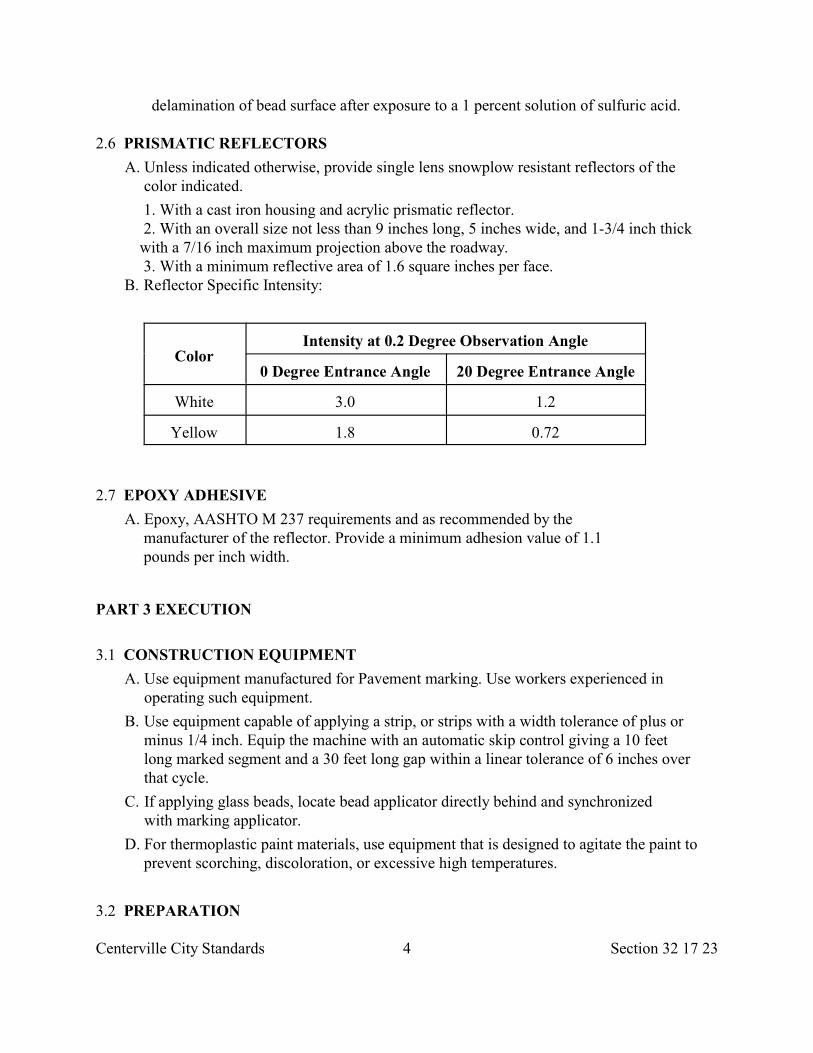
Centerville City Standards 4 Section 32 17 23
delamination of bead surface after exposure to a 1 percent solution of sulfuric acid.
2.6 PRISMATIC REFLECTORS
A. Unless indicated otherwise, provide single lens snowplow resistant reflectors of thecolor indicated.
1. With a cast iron housing and acrylic prismatic reflector. 2. With an overall size not less than 9 inches long, 5 inches wide, and 1-3/4 inch thick
with a 7/16 inch maximum projection above the roadway. 3. With a minimum reflective area of 1.6 square inches per face.
B. Reflector Specific Intensity:
ColorIntensity at 0.2 Degree Observation Angle
0 Degree Entrance Angle 20 Degree Entrance Angle
White 3.0 1.2
Yellow 1.8 0.72
2.7 EPOXY ADHESIVE
A. Epoxy, AASHTO M 237 requirements and as recommended by themanufacturer of the reflector. Provide a minimum adhesion value of 1.1pounds per inch width.
PART 3 EXECUTION
3.1 CONSTRUCTION EQUIPMENT
A. Use equipment manufactured for Pavement marking. Use workers experienced inoperating such equipment.
B. Use equipment capable of applying a strip, or strips with a width tolerance of plus orminus 1/4 inch. Equip the machine with an automatic skip control giving a 10 feetlong marked segment and a 30 feet long gap within a linear tolerance of 6 inches overthat cycle.
C. If applying glass beads, locate bead applicator directly behind and synchronizedwith marking applicator.
D. For thermoplastic paint materials, use equipment that is designed to agitate the paint toprevent scorching, discoloration, or excessive high temperatures.
3.2 PREPARATION
Centerville City Standards 5 Section 32 17 23
A. Broom or flush the surface to remove dirt, loose stones, or other foreign materialimmediately prior to applying.
B. Prior to applying, mark roadway between control points established by City Engineer.City Engineer will establish points on tangent at least every 100 feet and at 25 feet longintervals on curves. Maintain the line within 1 inch of the established control points. CityEngineer may also designate other Pavement striping locations such as stop bars,crosswalks, zebra striping, etc.
C. Markings that adhere to asphalt concrete or Portland cement concrete by either a pressuresensitive precoated adhesive or an epoxy cement shall mold to the Pavement contours bytraffic action at normal Pavement temperatures and shall be ready for traffic immediatelyafter application.
D. Begin Pavement painting and marking operations not later than 24 hours after receipt ofwritten order by City Engineer.
E. Apply striping and markings per MUTCD requirements.
F. Apply all materials in accordance with manufacturer's and City Engineer's directions.
3.3 APPLICATION
A. Apply Pavement paintings and markings only when Pavement surface is dry and airtemperature is above 40 deg. F. during daylight hours.
B. Do not apply paints and markings when rain is anticipated within 12 hours.
3.4 ALKYD RESIN PAINT STRIPING
A. Adjust Pavement striping machine to apply paint at rate recommended by paintmanufacturer.
B. Glass Bead Application Rate: 5.9 to 6.1 pounds per gallon of paint.
C. Protect the markings until dry by placing approved guarding or warning device wherevernecessary. Remove any markings not authorized or smeared or otherwise damaged, orcorrect as approved by City Engineer.
3.5 THERMOPLASTIC PAINT STRIPING
A. Clean off dirt, glaze, and grease before prestriping.
B. Prestripe the application area with a binder material that will form, when sprayed, acontinuous film over the Pavement surface, and will dry rapidly and mechanically adhereto the Pavement surface. Install the material in varying widths if indicated.
C. Extrude the thermoplastic material at a temperature of 412 plus or minus 12 deg. F. fromapproved equipment to produce a line 1/8 inch to 3/16 inch thick, continuous and uniformin shape, and have clean and sharp dimensions.
D. Do not use material which produce fumes that are toxic, obnoxious, or injurious to
Centerville City Standards 6 Section 32 17 23
persons or property.
E. Apply so that finished lines have well-defined edges free of waviness.
F. Glass Beads Application Rate: 6 pounds of glass beads to every 100 square feet ofmarking.
3.6 TAPE STRIPING
A. Apply Pavement marking tape as indicated or directed. City Engineer will establishcontrol points.
B. Apply the tape only on surfaces that are dry and free of oils, grease, dust and dirt, andprimed at the rate of approximately 1 quart per 60 feet with an approved primer material.
C. Maintain the line on established control points. Apply intermittent Pavement markingtape 24 inches long, spaced approximately 100 feet on tangents, and approximately 25feet on curves unless otherwise directed. The City Engineer will designate otherPavement striping locations such as stop bars, crosswalks, zebra striping, etc.
D. Press down the tape immediately after application until it adheres and conforms to thesurface of the Pavement.
E. Completely remove all tape on sections where tape conflicts with revised traffic lanesprior to opening new lanes to traffic.
3.7 PAVEMENT MARKING FILMS
A. Use Pavement marking films that are capable of being applied to new, dense, and open-graded asphalt concrete wearing courses during the paving operation in accordancemanufacturer's instructions, and that are capable of conforming to Pavement contoursthrough the action of traffic at normal Pavement temperatures.
B. Use a Pavement marking film that is capable of use for patching worn areas of thesame type film.
C. Apply before traffic is allowed on the freshly paved surface.
D. Unless indicated otherwise, provide Type C, Class II, polymer film markings inspecified widths and shapes. Provide and layout words and marking symbolconfigurations per MUTCD requirements and as indicated.
E. When indicated, inlay the markings in fresh asphalt surface by a compactionroller during the paving operation.
F. Apply all markings in accordance with manufacturer's recommendations.
3.8 PRISMATIC REFLECTOR INSTALLATION
A. Install reflectors by cutting Pavement and partially filling cut area with epoxy adhesive.Place reflector housing in the adhesive and apply pressure to properly seat. Allowepoxy to completely set before allowing traffic on markers.
Centerville City Standards 7 Section 32 17 23
B. Install marker so that housing edges are flush with Pavement and so that the angleformed by the longitudinal axis of the marker and the adjacent Pavement stripe does notexceed 5 degrees.
3.9 WORDS AND OTHER MARKINGS
A. Wet sandblast existing or temporary Pavement markings that may be confusing.Removal of markings by high-pressure water may be used if approved by City Engineer.
B. Apply word markings, letters, numerals and symbols with indicated stencils andtemplates.
3.10 TEMPORARY PAVEMENT MARKINGS
A. Renew when stripes and markings have lost 50 percent of their original visual effectiveness.
END OF SECTION
Centerville City Standards 1 Section 32 31 13
SECTION 32 31 13
CHAIN LINK FENCES AND GATES
PART 1 GENERAL
1.1 SECTION INCLUDES
A. Chain link fabric, posts, braces, anchorage, gates, miscellaneous hardware andappurtenances.
1.2 REFERENCES
A. ASTM A 53: Standard Specification for Pipe, Steel, Black and Hot-Dipped, Zinc-Coated, Welded and Seamless.
B. ASTM A 121: Standard Specification for Zinc-Coated (Galvanized) Steel Barbed Wire.
C. ASTM A 392: Standard Specification for Zinc-Coated Steel Chain-Link Fence Fabric.
D. ASTM A 491: Standard Specification for Aluminum-Coated Steel Chain-Link FenceFabric.
E. ASTM A 585: Standard Specification for Aluminum-Coated Steel Barbed Wire.
F. ASTM A 641: Standard Specification for Zinc-Coated (Galvanized) Carbon Steel Wire.
G. ASTM F 567: Standard Practice for Installation of Chain-Link Fence.
H. ASTM F 573: Standard Specification for Residential Zinc-Coated Steel Chain-Link FenceFabric.
I. ASTM F 626: Standard Specification for Fence Fittings.
J. ASTM F 654: Standard Specification for Residential Chain-Link Fence Gates.
K. ASTM F 668: Standard Specification for Poly(Vinyl Chloride) (PVC)-Coated SteelChain-Link Fence Fabric.
L. CLFMI: Chain Link Fence Manufactures Institute Product Manual for Chain Link FenceInstallation.
1.3 SUBMITTALS
A. Drawings: Indicate plan layout, grid, size and spacing of components, accessories, fittings,anchorage, and post section.
B. Data: Submit manufacturer's installation instructions and procedures, including details offence and gate installation.
C. Submit sample of fence fabric and typical accessories.
Centerville City Standards 2 Section 32 31 13
PART 2 PRODUCTS
2.1 GENERAL A. Galvanizing: Class 3, ASTM A 121. B. Aluminizing: Class 2, ASTM A 585.
C. Polyvinyl Chloride (PVC): With PVC coated materials, paint all posts, fittings, hardwareand accessories as indicated to match PVC color. The fabric shall be hot dippedgalvanized steel wire complying with ASTM A 392 and coated with a continuous PVCbonding process (minimum 15 mil thickness) in accordance with ASTM F 668. Color ofPVC coating as indicated and applied free of voids, cracks, tears and to have a smoothand lustrous surface.
D. Steel: Schedule 40, ASTM A 53.
E. Cast-in-place Concrete: Class 3000 minimum, Section 03 30 04.
2.2 CHAIN LINK FABRIC
A. 11 gage steel wire fabric for all fences less than 60 inches in height and 9 gage for fencesover 60 inches coated as follows.
1. Zinc coating, ASTM A 392. 2. Aluminum coating, ASTM A 491. 3. Polyvinyl chloride coating, ASTM F 668.
B. For residential fabric, provide zinc coated fabric, ASTM F 573 requirements.
C. Unless indicated otherwise use chain link fabric that has approximately 2 inches squaremesh and coated after fabrication.
D. Knuckle finish top edge and twist and barb bottom edge on fabric less than 60 incheswide. For fabric 60 inches or greater in width, twist and barb finish on both edges.Provide fabric that barbing has been done by cutting the wire on the bias.
E. If indicated, insert slats in fabric.
2.3 BARBED WIRE
A. Two strand, 12-1/2 gage wire with 14 gage, 4 point round barbs spaced approximately5 inches on center.
2.4 TENSION WIRES AND FABRIC TIES
A. Tension Wires: 7 gage galvanized coil spring steel wire, ASTM A 641.
B. Fabric Fasteners: 9 gage galvanized or 6 gage aluminum wire, or approved non-corrosive metal bands, for ties to fasten fabric to posts, rails, and gate frames. Fastenfabric to bottom tension wire spaced 24 inches on center.
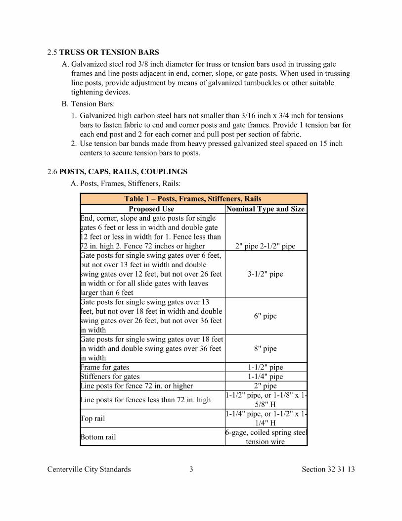
Centerville City Standards 3 Section 32 31 13
2.5 TRUSS OR TENSION BARS
A. Galvanized steel rod 3/8 inch diameter for truss or tension bars used in trussing gateframes and line posts adjacent in end, corner, slope, or gate posts. When used in trussingline posts, provide adjustment by means of galvanized turnbuckles or other suitabletightening devices.
B. Tension Bars:
1. Galvanized high carbon steel bars not smaller than 3/16 inch x 3/4 inch for tensionsbars to fasten fabric to end and corner posts and gate frames. Provide 1 tension bar foreach end post and 2 for each corner and pull post per section of fabric.
2. Use tension bar bands made from heavy pressed galvanized steel spaced on 15 inchcenters to secure tension bars to posts.
2.6 POSTS, CAPS, RAILS, COUPLINGS
A. Posts, Frames, Stiffeners, Rails:
Table 1 – Posts, Frames, Stiffeners, Rails
Proposed Use Nominal Type and Size End, corner, slope and gate posts for singlegates 6 feet or less in width and double gate12 feet or less in width for 1. Fence less than72 in. high 2. Fence 72 inches or higher 2" pipe 2-1/2" pipe Gate posts for single swing gates over 6 feet,but not over 13 feet in width and doubleswing gates over 12 feet, but not over 26 feetin width or for all slide gates with leaveslarger than 6 feet
3-1/2" pipe
Gate posts for single swing gates over 13feet, but not over 18 feet in width and doubleswing gates over 26 feet, but not over 36 feetin width
6" pipe
Gate posts for single swing gates over 18 feetin width and double swing gates over 36 feetin width
8" pipe
Frame for gates 1-1/2" pipe Stiffeners for gates 1-1/4" pipe Line posts for fence 72 in. or higher 2" pipe
Line posts for fences less than 72 in. high 1-1/2" pipe, or 1-1/8" x 1-
5/8" H
Top rail 1-1/4" pipe, or 1-1/2" x 1-
1/4" H
Bottom rail 6-gage, coiled spring steel
tension wire
Centerville City Standards 4 Section 32 31 13
B. Posts: Galvanized steel, at the indicated length.
C. Caps: Pressed galvanized steel or malleable iron designed to fit securely over post endsforming a weather tight closure. Where top rail is used, provide cap to permit passage oftop rail. "H" section posts do not require caps.
D. Top, Intermediate and Bottom Rails: Galvanized steel, in lengths as required. Providejoint couplings to connect rails securely. Provide means for attaching top rail securely toeach end, corner, line, slope and gate posts.
E. Joint Coupling: Galvanized steel, 6 inches long minimum for each joint. 1 coupling in 5shall have expansion spring. Couplings shall be outside sleeve type with bore of sleevetrue to maintain adjacent lengths of rail in alignment.
2.7 FITTINGS AND HARDWARE
A. Unless indicated otherwise, galvanize fittings and hardware.
B. Rivets: Make all hardware attachments with galvanized steel rivets.
2.8 SUPPORT OR EXTENSION ARM
A. Use support or extension arms for barbed wire that are of a type that can be attached tothe tops of the posts and carry the number of wires indicated.
B. Use only support arms on the fence for barbed wire that are capable of supporting a 250pound vertical load at the end of the arm without causing permanent deflection.
C. Single support arms are to be integral with a top post weather cap and have a hole forpassage of the top rail when required.
2.9 GATES
A. Residential gates: Refer to ASTM F 654 requirements.
B. Provide additional horizontal and vertical members to ensure proper gate operation andfor attachment of fabric, hardware and accessories.
C. Assemble gate frames and attach hardware by welding or by using fittings and rivets tomake rigid connections. Use same fabric as for fence. Install fabric with stretcher bars togate frame at not more than 15 inch on center.
D. Provide diagonal cross-bracing consisting of 3/8 inch diameter adjustable length trussrods on gates where necessary to prevent frame from sagging or twisting.
2.10 GATE HARDWARE
A. Hinges: Pressed steel or malleable iron to suit gate size, non-lift-off type, offset to permit180 degree gate opening. Provide minimum of one pair of hinges for each leaf.
B. Latch: Forked steel type or plunger-bar steel type to permit operation from either sideof gate. Provide locking device and padlock eye as integral part of latch.
Centerville City Standards 5 Section 32 31 13
C. Keeper: Provide keeper for all vehicle gates which automatically engages the gate leafand holds it in the open position until manually released.
D. Gate Stops: Mushroom type or flush plate with anchors set in concrete to engage thecenter drop rod or plunger bar.
E. Sliding Gates: Manufacturer's standard heavy-duty track, ball-bearing hanger sheaves,overhead framing and supports, guides, stays, bracing, steel wheel or rubber wheel, andaccessories as required.
PART 3 EXECUTION
3.1 PREPARATION A. Identify utility location. B. Excavation, Section 31 23 16.
C. Refer to ASTM F 567 and CLFMI products manual for chain link fence installation.
D. Protect roots and branches of trees and plants to remain.
E. Limit the amount of clearing and grading along the fence line to permit properinstallation.
3.2 LAYOUT OF WORK
A. Accurately locate and stake locations and points necessary forinstallation of fence and gates.
B. General arrangements and location of fence and gates are indicated. Install except forminor changes required by unforeseen conflicts with work of other trades.
3.3 INSTALLATION OF POSTS
A. Space line posts as follows:
1. Tangent sections to 500 feet radius: 10 feet maximum. 2. 200 feet radius to under 500 feet radius: 8 feet maximum. 3. 100 feet radius to under 200 feet radius: 6 feet maximum. 4. Under 100 feet radius: 5 feet maximum.
B. Provide pull posts at 500 feet maximum intervals. Changes in line of 30 degrees or moreare considered corners.
C. Set all posts to true line and grade in concrete bases or in approved pipe sleeves orsockets. Check for vertical and horizontal alignment.
D. Construct concrete bases for posts at least 10 inches in diameter. Place a minimum of 6inches concrete below each post. Depth of post in concrete as follows.
1. Line Posts: 18 inches.
Centerville City Standards 6 Section 32 31 13
2. End, Pull, Corner and Gate Posts Less Than 6 inches Diameter: 24 inches 3. Gate Posts: 30 inches.
E. Where posts are required to be set in concrete walls or masonry, set sockets for theposts to a depth of at least 18 inches. Use sockets that consist of lengths of 0.048 inchgalvanized metal pipe sleeves, with an inside diameter sufficient to allow the posts tofit loosely therein. Coat the inside of the socket and outside of the posts with anapproved bituminous paint. Caulk the posts securely in place with lead wool.
3.4 INSTALLATION OF BRACE ASSEMBLIES
A. Attached brace rail from end, pull, corner or gate posts to first ensuing line post. Installbraces so posts are plumb when diagonal truss rod is under proper tension.
3.5 INSTALLATION OF RAILS
A. Install rails level and plumb with grade between posts and attached to posts beforestretching fabric. Top rails shall form continuous brace from end-to-end of each run offence.
3.6 INSTALLATION OF FENCE FABRIC
A. Place fence fabric on security side of posts unless otherwise specified. Place fabricapproximately 1 inch above the ground. Maintain a straight grade between posts byexcavating high points of the ground. Filling depressions with soil will be permitted onlyupon approval of City Engineer.
B. Stretch the fabric taut and securely fasten to posts. Fasten to end, gate, corner, and pullposts. Secure stretcher bars with metal bands spaced at 15 inch intervals. Cut the fabricand fasten each span independently at all pull and corner posts. Fasten to line posts withtie wire, metal bands, or other approved methods at 15 inches intervals. Attach the topedge of fabric to the top rail or tension cable at approximately 24 inches intervals. Attachbottom tension wire to fabric with tie wires at 24 inches intervals and secure to the end ofpull posts with brace bands.
C. Draw barbed wire to assure minimum sag at high temperature and no breakage at lowtemperature. Connect the wires and arms by means of 0.142 gauge galvanized wirestays.
3.7 INSTALLATION OF GATES
A. Install gates plumb, level, and secure for full opening without interference. Installground-set items in concrete for anchorage as recommended by the fence manufacturer.Adjust hardware for smooth operation.
3.8 REPAIR DAMAGED COATING
Centerville City Standards 7 Section 32 31 13
A. Grind smooth and wire brush all welds made after galvanizing to remove loose or burnedzinc coating, after which neatly coat the areas with 50-50 solder or as otherwise directedby City Engineer. Make repairs to abraded or otherwise damaged zinc coating in a similarmanner. Replace PVC coating.
END OF SECTION
Centerville City Standards 1 Section 32 31 16
SECTION 32 31 16
WELDED WIRE FENCES AND GATES
PART 1 GENERAL
1.1 SECTION INCLUDES A. Wire fences and gates for roadway right-of-way lines.
1.2 REFERENCES
A. AASHTO M 133: Standard Specification for Preservatives and Pressure TreatmentProcess for Timber.
B. ASTM A 53: Standard Specification for Pipe, Steel, Black and Hot-Dipped, Zinc-Coated, Welded and Seamless.
C. ASTM A 116: Standard Specification for Zinc-Coated (Galvanized) Steel WovenWire Fence Fabric.
D. ASTM A 121: Standard Specification for Zinc-Coated (Galvanized) Steel BarbedWire.
E. ASTM A 585: Standard Specification for Aluminum-Coated Steel Barbed Wire.
F. ASTM A 641: Standard Specification for Zinc-Coated (Galvanized) Carbon SteelWire.
G. ASTM A 702: Standard Specification for Steel Fence Posts and Assemblies, Hot-Wrought.
H. NFPA 70: National Electric Code.
1.3 SUBMITTALS
A. Drawings: Indicate plan layout, grid, spacing of components,accessories, fittings, and anchorage.
B. Data: Submit manufacturer's installation instructions and procedures, including detailsof fence and gate installation.
PART 2 PRODUCTS
2.1 GENERAL
A. Galvanizing: Class 3, ASTM A 121.
B. Aluminizing: Class 2, ASTM A 585.
Centerville City Standards 2 Section 32 31 16
C. Polyvinyl Chloride (PVC): With PVC coated materials, paint all posts, fittings, hardwareand accessories as indicated to match PVC color. The fabric shall be hot dippedgalvanized steel wire complying with ASTM A 392 and coated with a continuous PVCbonding process (minimum 15 mil thickness) in accordance with ASTM F 668. Color ofPVC coating as indicated and applied free of voids, cracks, tears and to have a smoothand lustrous surface.
D. Steel Pipe: Schedule 40, ASTM A 53.
E. Cast-in-place Concrete: Class 3000 minimum, Section 03 30 04.
2.2 WIRE MESH FENCING
A. Class II, ASTM A 116, nominal 0.099 inch Farm Grade with a 6 inch vertical wire spacingwith wire mesh and spiral stays having a Class 1 zinc coating.
2.3 BARBED WIRE
A. Two strand, 12-1/2 gage wire with 14 gage, 4 point round barbs spaced approximately 5inches on center.
2.4 UNTREATED WOOD POSTS FOR LINES, GATES, ENDS AND CORNERS
A. Line posts: 10 inches minimum circumference Juniper or acceptable alternate approvedby ENGINEER.
B. Gate, Brace, and Corner Posts: 12 inches minimum circumference minimum Juniperor acceptable alternate approved by City Engineer.
C. Use only sound straight posts that are free from decay or defects.
2.5 TREATED WOOD POSTS AND WOOD BRACE RAILS
A. Douglas Fir, Hemlock, or Pine as follows.
1. Line Posts: 10 inches minimum circumference. 2. Gate, Brace, and Corner Posts: 12 inches minimum circumference. 3. Rectangular Posts: 12 square inches minimum normal cross-section area. Square
members may be rough sawn or finished. B. Treat timber according to AASHTO M 133. Pressure treat wood members prior to
fabrication.
C. Prior to painting, treat lumber per AASHTO M 133 requirements using pentachloro-phenolsolution.
D. Sawing or field drilling of holes is allowable if all exposed untreated surfaces ofmembers are field treated with 2 coats of the same material originally treated.
2.6 METAL POSTS AND BRACES
Centerville City Standards 3 Section 32 31 16
A. Steel posts, ASTM A 702.
B. The anchor plate may be omitted provided posts are set in a concrete footing with aminimum cross-sectional dimension of 6 inches and a depth equal to full penetration ofthe post plus 6 inches.
C. Galvanized posts may be used in the place of the painted posts. Use posts galvanized bythe hot-dipped process.
2.7 TUBULAR STEEL FRAME GATE WITH WIRE FABRIC
A. Gate frames manufactured with steel pipe 1 inch nominal diameter steel pipe minimum.
B. Place steel pipe braces vertically in each drive gate to provide uniform size panels.Provide one vertical support for 10 and 12 feet wide gates and 2 vertical supports for 14to 16 feet wide gates.
C. Gate dimensions are the minimum clear openings between gate posts. Provide a gatewith fittings to fill the opening.
D. Provide galvanized woven wire fabric of the same type and quality as indicated for thefence and space the horizontal wires corresponding to that of the fence. Provide anadjustable steel truss rod of 3/8 inch minimum diameter to prevent sagging on gates 10feet or more in length.
E. Galvanize steel fitting and hardware, Section 05 05 10.
F. For 10 feet wide and wider gates use pintles not less than 5/8 inch diameter.
G. For fasteners for single gates furnish an 18 inches length of galvanized chain secured tothe gate at one end and fitted with a snap fastener on the loose end. For all double drivegates use a center latch in lieu of a chain fastener with a pin that fits in a socket embeddedin concrete.
H. For sliding gates use a frame made from 1-1/4 inch steel tubing with fence fabric equalto the adjoining fence. Support the opening end on a set of 6 inches minimum diameterwheels. Provide a 1-1/2 inch minimum schedule 40 pipe to support the other end with asteel wheel that rides on the support pipe. On gates wider than 12 feet use 2 supportpipes. If a pre-manufactured gate is to be used, submit details for review.
2.8 STAPLES
A. Galvanized steel No. 9 wire 1-1/2 inches long minimum with an ASTM A 641, Class Icoating.
PART 3 EXECUTION
3.1 PREPARATION
A. Identify utility location.
Centerville City Standards 4 Section 32 31 16
B. Excavation, Section 31 23 16.
C. Limit the amount of the clearing and grading along the fence line to permit properinstallation.
3.2 INSTALLATION
A. Install permanent end braced posts for existing cross fences which are intersected bythe new fence alignment. Place all end braced posts in position in existing cross fenceto serve as line posts for connection to the new fence. Space fence posts at intervalsand depth indicated. Install all posts in a vertical position.
B. After wood post has been set, cut off top to height indicated at an angle ofapproximately 30 degrees from horizontal.
C. Brace corner and end post in two directions.
D. Set metal corner, end, gate, and brace posts in concrete footings that are 12 inches largerin diameter than the post and at least 24 inches deep. Crown top to shed water. Install nomaterials on posts or place strain on guys until 7 days after placing concrete.
E. Draw wire mesh fabric tight to remove all sag.
F. Excavate high points along the ground surface that interferes with placing of wiremesh. Provide a minimum clearance of 1 inch and 4 inches maximum.
G. Draw barbed wire to assure minimum sag at high temperatures and no breakage at lowtemperatures. Connect the lateral wires between the posts by means of 0.142 inchdiameter galvanized wire stays of the length indicated.
H. Fasten the top and bottom wires and every alternate lateral wire in the mesh fabric andeach strand of barbed wire to each post by means of the staple or clamp.
I. Connect wood braces to adjacent posts with 3/8 inch x 4 inch galvanized steel dowels andtension the brace wires until the installation is rigid.
J. Fasten metal braces to the metal post by the use of a securely bolted assembly or buttwelding.
K. Provide double diagonal wire bracing at each timber bracing consisting of two 0.192inch diameter galvanized wires securely fastened to wood posts.
L. Construct gates to operate freely without sag. Provide fittings and locks.
M. At each location where an electric transmission distribution or secondary line crosses anyfence with wood posts, install an electric ground conforming to NFPA 70 requirements.
END OF SECTION
Centerville City Standards 1 Section 32 32 26
SECTION 32 32 26
CRIB WALLS
PART 1 GENERAL
1.1 SECTION INCLUDES
A. Fabrication and installation requirements for modular concrete crib or steel cribretaining walls.
1.2 REFERENCES
A. AASHTO M 36: Standard Specification for Metallic (Zinc or Aluminum) CoatedCorrugated Steel Culverts and Underdrains.
B. AASHTO M 243: Standard Specification for Field Applied Coating of CorrugatedMetal Structural Plate for Pipe, Pipe-Arches, and Arches.
1.3 SUBMITTALS
A. Shop Drawings or manufacturer's specifications showing the components to be used,erection and component tolerances, overall layout, typical construction details, andconstruction procedures.
B. Specific engineered design calculations for the particular wall.
PART 2 PRODUCTS
2.1 GENERAL
A. Concrete crib retaining walls consist of cribs composed of headers, stretchers, closers,and false headers. These components are held together principally by friction and arefilled with crushed Rock or soil. The cribs can be interlocked to increase base width andwall mass.
B. Metal bin retaining walls consist of a plurality of pairs of columns, one column of eachpair is in the plane of the front wall and the other column is in the plane of the rear of thewall. The pairs of columns are spaced longitudinally with overlapping S-shaped facingand rear members (stringer). They are shaped transversely with overlapping U-shaped tiemembers (spacers).
C. Hot dip galvanize all metal materials, including bolts, appurtenances, and connections.
Centerville City Standards 2 Section 32 32 26
2.2 MANUFACTURE OF CONCRETE CRIBWALL COMPONENTS
A. Concrete and Steel for Manufacture of Components:
1. Cast-in-place Concrete: Class 4000, Section 03 30 04. 2. Reinforcement: Steel, Section 03 20 00.
B. Lengths and widths of component surfaces in contact with the molds during manufacture shall not depart from nominal approved design values by morethan plus or minus 1/8 inch.
C. Distances between bearing surfaces shall not depart from the nominal design value bymore than plus or minus 1/16 inch.
D. Bearing surfaces shall be parallel to within plus or minus 1/32 inch in the width of theunits.
E. All components except false headers shall contain reinforcing steel that extends to within1-1/2 inches of the end of the unit. In no case shall the diameter of the reinforcing steel beless than 3/8 inch.
F. All reinforcing steel shall be covered by a minimum of 1/2 inch of concrete at thetime of manufacture.
2.3 FABRICATION OF METAL BINS
A. Steel bin materials of the shapes and dimensions indicated.
B. Gage or thickness of wall construction members: Not less than 0.06 inch nominal.
C. When forming units, maintain a minimum-forming radius of 1 inch, or if units are formedwith less than 1 inch radius, hot-dip galvanize after forming.
D. Assemble units into a continuous closed faced wall of connected bins.
E. Fabricate all units of the same nominal size so they are fully interchangeable. Nodrilling, punching, or drifting to correct defects in manufacturing will be permitted.Any units having holes improperly punched or galvanized shall be rejected.
F. Field coat all buried portions and the back side of metal bin retaining wall units withasphalt mastic in accordance with AASHTO M 243.
2.4 ACCESSORIES
A. Fill: Use only crushed Rock with a maximum diameter of 3 inches or an approved soil fillwhich is free from organic matter and conforms to the gradation limits of 100 percentpassing a 3 inches sieve and not more than 15 percent passing a number 200 sieve.
B. Geotextile: Woven or nonwoven fabric, Section 31 05 19.
PART 3 EXECUTION
Centerville City Standards 3 Section 32 32 26
3.1 PREPARATION
A. Excavation, Section 31 23 16.
B. Excavate for wall construction to 18 inches below finish ground line at the toe of thewall and slope the Excavation to the heel of the wall at the appropriate counter-batter asindicated in Developer's submitted design calculations.
C. The material under the base of the wall shall be either undisturbed native soil free fromorganic matter or an approved crushed aggregate base that is compacted equal to orgreater than 90 percent of maximum dry density.
D. Install required geotextile, Section 31 05 19.
3.2 BACKFILLING AND COMPACTION
A. Place fill carefully in lifts not exceeding 12 inches uncompacted depth and workbetween parallel crib wall components.
B. If soil is used for wall fill, compact the fill equal to or greater than 90 percent ofmaximum dry density within the rear 2/3 of the face crib and in all multiple cribs.
C. Place and compact the backfill behind the cribs concurrently with the filling of thecribs.
3.3 ERECTION -GENERAL
A. Obtain site review by City Engineer after wall and base cuts are completed and prior tostart of wall construction.
B. Up to 2 inches of sand or fine gravel may be used on top of the prepared base to adjustthe exact elevation of the base course of closers.
C. Handle component units carefully. Repair or replace damaged units.
D. Maintain all field tolerances to within plus or minus 1/2 inch in 10 feet of the nominaldesign tolerances.
E. Do not exceed the maximum height shown in the engineered wall calculations foreach crib width shown.
F. In the construction of a wall on a curve, obtain the proper curvature for the face by theuse of shorter stringers in the front or rear panels of retaining walls.
3.4 ERECTION -CONCRETE CRIB WALL
A. If cutting of the units requires the exposure of the ends of the reinforcing steel, coat theexposed steel with an epoxy or an asphaltic cement.
B. If shims are required to maintain tolerances in wall, only shims made from asphalticfelt or fiberglass roofing material shall be permitted.
3.5 ERECTION -STEEL CRIB WALL
Centerville City Standards 4 Section 32 32 26
A. Bolt the ends of steel stringers to corner columns by means ofconnecting channels.
B. Coat field cut of steel ends in accordance with AASHTO M 36.
C. The wall height and depth may be varied. Do not exceed the maximum dimensionsshown for the design selected. Two or more retaining walls may be incorporated in thesame wall by the use of standard split columns to make the connection on the step-back.
END OF SECTION
Centerville City Standards 1 Section 32 84 23
SECTION 32 84 23
UNDERGROUND IRRIGATION SYSTEMS
PART 1 GENERAL
1.1 SECTION INCLUDES
A. Underground Irrigation System complete with heads, valves, controls, and accessories.
1.2 REFERENCES
A. NFPA 70: National Electric Code.
1.3 DEFINITIONS
A. Lateral Pipe: That system of pipes downstream of a pressure valve. Lateral pipe feedswater to sprinklers and emitters.
B. Irrigation System: The arrangement of valves, controls, heads and accessoriesincluding lateral and mainline pipe systems.
C. Mainline Pipe: That system of pipes upstream of a pressure pipe valve.
1.4 PERFORMANCE REQUIREMENTS
A. Design Pressure: As indicated from connection to supply system to last head in circuit.
B. Location of Heads: Design location is approximate. Make adjustments as necessary toavoid plantings and other obstructions.
C. Water Coverage: Turf and other planting areas, 100 percent. Modify layout to obtaincoverage and rate of application and to suit manufacturer's standard heads. Do notdecrease number of heads indicated unless acceptable to City Engineer.
D. Pipe Testing Schedule: Section 33 08 00.
E. Leave system dry if Work is Substantially Completed after October 15 unless directedotherwise by City Engineer.
1.5 SUBMITTALS
A. Product Data: Manufacturer's technical data and installation instructions.
B. Layout Drawings: Plan layout and details illustrating piping layout to water supplylocation and type and coverage of heads, valves, piping circuits, controls, landscapingfeatures, list of fittings and accessories.
C. Pipeline Test Report: Section 33 08 00.
D. Operation and Maintenance Data: Section 01 78 23.
Centerville City Standards 2 Section 32 84 23
1. Submit instructions covering full operation, care, and maintenance of system (and controls) and manufacturers parts catalog.
2. Include year-to-year schedule showing length of time each valve is to be open to provide determined amount of water, drain procedures, cleanout features, etc.
3. Instruct Developer’s maintenance personnel how to operate controller and adjust sprinkler heads.
E. Manual Valve Key Operator: Furnish 3 valve keys, 3 feet long with tee handle and keyend to fit each type of valve assembly.
PART 2 PRODUCTS
2.1 PIPE, FITTINGS, OTHER
A. Material: PVC, Section 33 05 07.
B. Pressure Pipe: Schedule 40.
1. Solvent weld smaller than 3 inches. 2. Mechanical joint 3 inches and larger
C. Lateral Pipe: Schedule 40 through 1-1/4” then Class 200, solvent welded.
D. Fittings: Schedule 40, solvent welded or threaded.
E. Risers: Schedule 80, threaded.
F. Water Valve Assemblies: Schedule 80, threaded.
2.2 VALVES
A. Manual Valve: Gate type with cast bonze body, resilient integral taper seat, non-risingstem, and fitted for key operation.
B. Automatic Valve: Globe type operated by low-power replaceable solenoid,normally closed, and fitted for manual flow adjustment
C. Automatic Drain Valve: Designed to open for drainage when line pressure dropsbelow 3 psi. (NOT for use on mainline pipe.)
2.3 DRAIN SUMP
A. Sewer rock or pea gravel, Section 31 05 13.
2.4 BACKFLOW PREVENTER A. Manufacturer's standard, to suit sprinkler system and the following.
1. Double check valve. 2. When underground Irrigation System is designed for liquid fertilizer, provide a reduced
pressure backflow prevention device. The drain to daylight must be a minimum of 12 inches below the bottom of the release valve for devices 4 inches in diameter and
Centerville City Standards 3 Section 32 84 23
smaller, or 12 inches plus the nominal diameter of the devices over 4 inches in diameter.
2.5 SPRINKLER HEADS A. Manufacturer's standard unit designed to provide uniform coverage over entire area of
spray indicated at available water pressure, as follows:
1. Flush Surface: Fixed pattern, with screw-type flow adjustment. 2. Bubbler: Fixed pattern, with screw-type flow adjustment. 3. Shrubbery: Fixed pattern, with screw-type flow adjustment. 4. Pop-Up Spray: Fixed pattern, with screw-type flow adjustment and stainless steel
retraction spring. 5. Pop-Up Rotary Spray: Gear driven, full circle and adjustable part circle type. 6. Pop-Up Rotary Impact: Impact driven, full circle and part circle as indicated. 7. Above-Ground Rotary Impact: Impact driven, full circle and part circle as indicated.
2.6 VALVE BOX
A. Precast concrete or plastic with adequate hand room to operate small tools andprovisions for locking cover to frame.
B. For drain pockets, No. 2 gravel (2-1/2 inch) Section 31 05 13.
2.7 AUTOMATIC CONTROL SYSTEM
A.General: Furnish low voltage system manufactured expressly for control of automaticcircuit valves of underground Irrigation Systems. Provide unit of capacity to suit numberof circuits.
B. Control Enclosure -External Applications: Manufacturer's standard weatherproofenclosure with locking cover, complying with NFPA 70.
C. Control Enclosure -Internal Applications: Manufacturer's standard with locking cover,complying with NFPA 70.
D. Transformer: To convert service voltage to control voltage and in accordance withmanufacturer's recommendations.
E. Circuit Control: Each circuit variable from approximately 5 to 60 minutes. Includeswitch for manual or automatic operation of each circuit.
F. Timing Device: Adjustable, 24 hour and 14 day clocks to operate any time of day andskip any day in a 14 day period. Allow for manual or semiautomatic operation withoutdisturbing preset mechanical operation.
G. Wire:
1. Provide wire for connecting remote control valves to the automatic controllers that is Type "UF", 600 volt, stranded or solid copper, single conductor wire with PVC insulation and bearing UL approval for direct underground burial feeder cable. Make all connections with UL approved type seal to make a waterproof connection. Bury
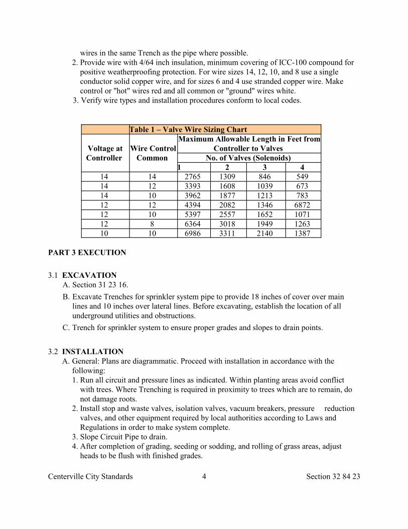
Centerville City Standards 4 Section 32 84 23
wires in the same Trench as the pipe where possible. 2. Provide wire with 4/64 inch insulation, minimum covering of ICC-100 compound for
positive weatherproofing protection. For wire sizes 14, 12, 10, and 8 use a single conductor solid copper wire, and for sizes 6 and 4 use stranded copper wire. Make control or "hot" wires red and all common or "ground" wires white.
3. Verify wire types and installation procedures conform to local codes.
Table 1 – Valve Wire Sizing Chart
Voltage atController
Wire ControlCommon
Maximum Allowable Length in Feet fromController to Valves
No. of Valves (Solenoids) 1 2 3 4
14 14 2765 1309 846 549 14 12 3393 1608 1039 673 14 10 3962 1877 1213 783 12 12 4394 2082 1346 6872 12 10 5397 2557 1652 1071 12 8 6364 3018 1949 1263 10 10 6986 3311 2140 1387
PART 3 EXECUTION
3.1 EXCAVATION A. Section 31 23 16.
B. Excavate Trenches for sprinkler system pipe to provide 18 inches of cover over mainlines and 10 inches over lateral lines. Before excavating, establish the location of allunderground utilities and obstructions.
C. Trench for sprinkler system to ensure proper grades and slopes to drain points.
3.2 INSTALLATION A. General: Plans are diagrammatic. Proceed with installation in accordance with the following:
1. Run all circuit and pressure lines as indicated. Within planting areas avoid conflict with trees. Where Trenching is required in proximity to trees which are to remain, do not damage roots.
2. Install stop and waste valves, isolation valves, vacuum breakers, pressure reduction valves, and other equipment required by local authorities according to Laws and Regulations in order to make system complete.
3. Slope Circuit Pipe to drain. 4. After completion of grading, seeding or sodding, and rolling of grass areas, adjust
heads to be flush with finished grades.
Centerville City Standards 5 Section 32 84 23
B. Piping: 1. Assemble all circuit and pressure pipe in accordance with manu-facturer's
recommendations and assure positive drainage. 2. At wall penetrations, pack the opening around the pipe with Section 03 61 00 non-
shrink grout. At exterior face, fill perimeter slot with backer rod and sealant. Repair below grade waterproofing and make penetration watertight.
3. Install PVC pipe in dry weather above 40 deg. F. Allow joint to cure a minimum of 8 hours before testing. C. Sleeves:
1. Install sleeves before concrete work. 2. Under roadway, install PVC sleeve if cover over sleeve exceeds 2 feet, otherwise use
cast iron or ductile iron sleeve. D. Control Valves:
1. Install remote control valves to manufacturer's recommendation. 2. Use Schedule 80 PVC pipe for nipples on valve header, length as necessary. Install
valves one per each plastic valve box and provide 12 inches of expansion loop slack wire at all connections inside valve box. E. Automatic Drains: Install in accordance with manufacturer's recommendations at the low point of circuit lines. Do not use this valve on pressure pipe systems. F. Manual Drains:
1. Install per manufacturer's recommendations on upstream and downstream side of backflow preventers and at lowest point along main pressure pipe.
2. Install by teeing down to 3/4 inch drain valve. Provide a drainage sump sized to receive volume of drain water.
3. Make manual drain valves accessible by installing an adjustable pipe sleeve to meet finished grade with locking valve marker lid flush with finish grade. G. Quick-Coupling Valves:
1. Install using 3/4 inch flexible lateral with galvanized elbow and riser. Locations as indicated. H. Backflow Preventers:
1. Install assembly complete for sprinkler systems with 2 drain valves and 2 shut off valves per local Laws and Regulations, and manufacturer's specifications.
2. In below grade installations install assemblies with drain valves. Provide open box floor with gravel drain sump. I. Valve Access Boxes:
1. Install over all remote control valves, manual control valves, zone shutoff valves, gate valves or globe valves. Valves to be installed using valve markers will not require access boxes.
2. Install boxes on level Subgrade to proper grade and proper drainage. 3. Provide boxes with proper length and size extensions.
J. Automatic Controller: 1. Mount the panel enclosure so adjustments can be conveniently made by the operator. 2. Ground controller per local Laws and Regulations.
Centerville City Standards 6 Section 32 84 23
3. Make all control wire connections to automatic controllers. 4. Coordinate controller installation with electrical work.
K. Wire and Electrical Work: 1. Use electrical control and ground wire suitable for sprinkler control cable of size
indicated. L. Sprinkler Heads, Emitters, Bubblers, Small Rotators (less than 10 gallons per minute). .
1. Install with flexible lateral and spiral barged PVC elbows and riser (length as required).
2. Install shrub spray heads a minimum of 12 inches above finished grade of plantings. 3. Install tree bubblers 1/2 inch below crown of tree roots. 4. Flush circuit lines thoroughly. Remove all foreign materials prior sprinkler head
installation. M. Large Rotator Heads (10 gallons per minute or more): Install pressurized swings joints with O-ring seals. N. Swivel Hose Elbows:
1. Install brass swivel hose elbows, accurately machined pipe with hose threads and "O" ring seals.
3.3 BACKFILLING OPERATION A. Section 33 05 20.
B. Backfill to 6 inches above pipe with soil free of rocks over 1 inch diameter, debris, ororganic matter. Backfill final 4 inches with soil of like quality to adjacent areas.
C. Compact backfilled Trenches thoroughly to prevent settling damage to grades or plantmaterials.
D. Piping may be tested in sections to expedite backfilling.
3.4 SURFACE RESTORATIONS
A. Protect existing landscaping.
B. Refer to Sections 32 92 00 and 32 93 13. Replace damaged plants and lawn areas with newto match existing.
END OF SECTION
Centerville City Standards 1 Section 32 91 19
SECTION 32 91 19
LANDSCAPE GRADING
PART 1 GENERAL
1.1 SECTION INCLUDES A. Landscaping grading requirements. B. Backfill materials.
1.2 SUBMITTALS
A. Submit maximum laboratory dry density and optimum laboratory moisture contentfor:
1. Subgrade material, and 2. Each type of fill to be used.
B. Upon City Engineer's request, submit a written quality control Inspections and testingreport describing source and field quality control activities performed by Developer andits Suppliers.
1.3 QUALITY ASSURANCE
A. Do not change material sources, or aggregate without City Engineer's knowledge.
B. Reject backfill material that does not comply with requirements specified in this section.
C. Landscape grading is aesthetic by nature and subject to continual monitoring andmodification during the backfilling process. Work closely with City Engineerparticularly when grading and construction berms, channels, or other aestheticconsiderations.
1.4 STORAGE
A. Safely stockpile backfill materials.
B. Separate differing materials, prevent mixing, and maintain optimum moisture contentof backfill materials.
C. Avoid displacement of and injury to Work while compacting or operatingequipment.
D. Movement of construction machinery over Work at any stage of construction issolely at Developer's risk.
1.5 SITE CONDITIONS
A. Do not place, spread, or roll any backfill material over material that is damaged by
Centerville City Standards 2 Section 32 91 19
water. Remove and replace damaged material at no additional cost to OWNER.
B. Control traffic and erosion. Keep area free of trash and debris. Repair settled, eroded,and rutted areas.
C. Reshape and compact damaged structural section to required density.
1.6 ACCEPTANCE
A. Native material may be wasted if there is no additional cost to substitute materialacceptable to City Engineer.
B. For material acceptance refer to.
1. Common fill, Section 31 05 13. 2. Crushed aggregate base, Section 32 11 23. 3. Cement treated fill, Section 31 05 15.
1.7 WARRANTY
A. Any settlement noted in landscaped surfaces will be considered to be caused byimproper compaction methods and shall be corrected.
B. Restore incidentals damaged by settlement.
PART 2 PRODUCTS
2.1 BACKFILL MATERIALS
A. Common fill, Section 31 05 13.
B. Crushed aggregate base, Section 32 11 23.
C. Cement treated fill, Section 31 05 15.
2.2 ACCESSORIES
A. Water: Make arrangements for sources of water during construction and makearrangements for delivery of water to site. Comply with local Laws and Regulations whensecuring water from water utility company.
PART 3 EXECUTION
3.1 PREPARATION
A. Identify required line, levels, contours, and datum.
B. Stake and flag locations of underground utilities.
C. Upon discovery of unknown utility or concealed conditions, notify City Engineer.
Centerville City Standards 3 Section 32 91 19
D. Verify stockpiled fill meets gradation requirements, areas to be backfilled are free ofdebris, snow, ice or water, and ground surface is not frozen.
E. If subgrade is not readily compactable secure written authorization for extra excavationand backfill. Refer to Section 31 23 16.
3.2 PROTECTION
A. Protect existing trees, shrubs, lawns, existing structures, fences, roads, sidewalks,paving, curb and gutter and other features.
B. Protect above or below grade utilities. Contact utility companies to repair damage toutilities. Pay all cost of repairs.
C. Protect Subgrade from desiccation, flooding and freezing.
D. Do not fill adjacent to structures until Excavation is checked by City Engineer.
E. Do not use compaction equipment adjacent to walls or retaining walls that may causewall to become over-stressed or moved from alignment.
F. Do not disturb or damage foundation perimeter drainage, foundation, damp-proofing,foundation waterproofing and protective cover, or utilities in Trenches.
G. Restore any damaged structure to its original strength and condition.
3.3 LAYOUT
A. Maintain all benchmarks, control monuments and stakes, whether newly established bysurveyor or previously existing. Protect from damage and dislocation.
3.4 GRADING
A. Grading Intent: Spot elevations and contours indicated are based on the best availabledata. The intent is to maintain constant slopes between spot elevations. If a spotelevation is determined to be in error, or the difference in elevation between pointschange, then the minimum percentage of slope as a result of field adjustment of specificspot elevations is as follows:
1. Pavement Areas: 1 percent. 2. Concrete or Brick Areas: 0.30 percent. 3. Lawn or Planted Area: 0.75 percent.
B. Conduct Work in an orderly manner. Do not create a nuisance. Do not permit soilaccumulation on streets or sidewalks. Do not allow soil to be washed into sewers andstorm drains.
C. Grade slopes to provide adequate drainage after compaction. Do not create waterpockets or ridges. Use all means necessary to prevent erosion of freshly graded areasduring construction until surfaces have been constructed and landscaping areas havetaken hold.
Centerville City Standards 4 Section 32 91 19
D. Remove surface stones greater than 1 inch from finished grading.
E. In planting areas, provide a finished grade that conforms to Section 32 92 00 andSection 32 93 13.
3.6 MODIFIED BACKFILL LAYER METHOD
A. Refer to Section 33 05 20.
3.7 COMPACTION A. Compact backfill, Section 33 05 05
3.8 SURFACE RESTORATION A. Restore paved surfaces, Section 33 05 25.
B. Finish landscaped surfaces with grass, Section 32 92 00 or with other ground cover,Section 32 93 13.
1. Backfill areas to contours and elevations indicated. Do not use frozen materials. 2. Make smooth changes in grade. Blend slopes into level areas. 3. Remove surplus backfill materials from site. 4. Leave stockpile areas completely free of excess fill materials. 5. Slope grade away from building at a minimum of 3 inches in 10 feet unless specified
otherwise.
3.9 CLEANING
A. Remove stockpiles from the site. Grade site surface to prevent free standing surfacewater.
B. Leave borrow areas clean and neat.
END OF SECTION
Centerville City Standards 1 Section 32 92 00
SECTION 32 92 00
TURF AND GRASSES
PART 1 GENERAL
1.1 SECTION INCLUDES A. Seed and sod requirements. B. Soil preparation and fertilizers.
1.2 REFERENCES A. FS O-F-241: Fertilizers, Mixed, Commercial. B. ASPA: Guideline Specifications for Sodding.
1.3 SUBMITTALS A. Submit name of sod Supplier or location. B. Submit laboratory analysis of top soil, if requested by City Engineer.
1.4 DELIVERY, STORAGE, AND HANDLING
A. Deliver grass seed in original containers showing analysis of seed mixture, percentageof pure seed, year of production, net weight, date and location of packaging. Damagedpackages are not acceptable.
B. Strip sod no more than 24 hours prior to laying.
C. Deliver fertilizer in containers showing weight, chemical analysis, and name ofmanufacturer. Store fertilizer in a weatherproof location.
PART 2 PRODUCTS
2.1 SEED
A. Furnish grass seed that is fresh, clean, and new crop composed of varieties indicated andtested to have minimum of 90 percent purity and minimum of 80 percent germination.
B. Use seed that conforms to applicable Laws and Regulations.
C. Do not use wet, moldy or otherwise damaged seed.
2.2 SOD
A. Obtain all shipments of sod from approved sources.
B. Mowed regularly and carefully maintained from planting to harvest to assure reasonablequality and uniformity.
Centerville City Standards 2 Section 32 92 00
C. Free of grassy and broadleaf weeds, and bare or burned spots.
D. Clean, strongly rooted sod of variety indicated.
E. Cut sod in pieces not exceeding 1 square yard. Limit depth of cut to 1/2 inch minimumand 1 inch maximum.
2.3 TOP SOIL A. Section 31 05 13.
2.4 ACCESSORIES
A. Fertilizer: Uniform in composition, dry and free flowing. Comply with FS O-F-241.Provide nutrients required by soil analysis.
B. Mulching Material: Wood or wood cellulose fiber free of growth or germinationinhibiting ingredients.
PART 3 EXECUTION
3.1 PREPARATION
A. Protect existing underground improvements from damage.
B. Do not place turf and grasses until existing weeds have been removed and soil hasbeen prepared.
C. Do not sow immediately following rain, when ground is too dry, too hard, or duringwindy periods without first loosening the surface.
3.2 GRADING A. Establish finished grades after settling to provide adequate drainage so no water pockets
or ridges will be created. B. Till soil to a depth of 4 inches and remove rocks and debris over 2 inches diameter and
any vegetation and weeds. Fine grade entire site to a smooth, loose, and uniform surface.Use native or approved imported topsoil and plant after proper preparation.
C. When Subgrade has been established, roll areas to remove ridges and depressions sosurface is parallel with finished grade. Limit weight of rolling equipment to 110 poundsminimum or 250 pounds maximum per square foot.
D. Site tolerances. 1. Total topsoil depth for lawns or grasses: 5 inches. 2. Elevation of topsoil relative to walks, hard surfaces or edges.
a. Seed Areas: 1/2 inch below. b. Sod Areas: 1-1/2 inch below.
3. Slope away from building 5 percent for 10 feet minimum. Fill low spots and pockets.High point of finish grade shall be at least 6 inches below finish floor level.
Centerville City Standards 3 Section 32 92 00
3.3 FERTILIZING
A. Apply fertilizer in formulation and quantity required by soil analysis.
B. Apply after fine grading and mix thoroughly into upper 2 inches of topsoil.
C. Do not apply grass seed and fertilizer at same time in same machine unless one step hydroseeding is used.
D. Lightly water to aid breakdown of fertilizer and to provide moist soil for seed.
3.4 SEEDING
A. Unless indicated otherwise, apply seed at a rate of 5 pounds per 1,000 square feetevenly in 2 intersecting directions. Rake in lightly.
B. Apply fine spray water immediately after each area has been sown.
3.5 ONE STEP HYDRO SEEDING
A. Unless indicated otherwise, on lawn areas apply seed at the rate of 5 pounds per 1,000square feet and fertilizer at the rate of 15 pounds per 1,000 square feet of area.
B. Mix the seed and fertilizer with a specially prepared dyed wood cellulose fiber and waterto form a slurry.
C. Mix the slurry in tanks having continuous agitation so that a homogenous mixture isdischarged hydraulically on the area to be seeded.
D. Apply the wood fiber mulch in suspension at a rate of 2,000 pounds per acre or asindicated otherwise.
3.6 TWO STEP HYDRO SEEDING
A. Make soil surface smooth, loose and of uniformly fine texture prior to seeding. Do notprepare more ground than can be seeded in a work day period.
B. Mix fertilizer at a rate of 15 pounds per 1,000 square feet, with wood fiber mulch andwater to form a slurry.
C. Maintain a well mixed fertilizer slurry in the mix tank.
D. Spray the fertilizer mixture at the rate of 2,000 pounds per acre.
E. Sow seed on fertilized areas at the rate of 5 pounds per 1,000 square feet of area, in 2directions with a cyclone seeder or other approved mechanical seeder.
3.7 SEED PROTECTION ON SLOPES
A. Blankets: Section 31 25 00.
3.8 LAYING SOD
Centerville City Standards 4 Section 32 92 00
A. Maintain the sod moist, live, and in good condition to encourage immediategrowth.
B. Comply with ASPA guidelines for sodding.
C. Lay the sod on smooth, moist topsoil, working off planks if required. Rake topsoil toloosen and level prior to placing each course of sod. Ensure that sod is not stretched oroverlapped and that all joints are butted tight. Place sod to break joints on ends. Keeplength seams in a straight line.
D. Roll sod immediately after placing. Thoroughly water with a fine spray to a depthsufficient that the underside of the new sod and soil immediately below the sod arethoroughly wet.
E. On slopes 2 horizontal to 1 vertical and steeper, lay sod perpendicular to slope and secureevery row with wooden pegs at 2 feet maximum on center. Drive pegs flush with soilportion of sod.
3.9 RESTORATION
A. Restore Pavement, concrete, grassed areas, planted areas, and other improvementsdamaged during execution of work of this section to a condition equal to originalconditions.
3.10 MAINTENANCE
A. Section 32 01 90.
B. Remove from site foreign materials collected during cultivation.
C. Dispose of cleanings.
END OF SECTION
Centerville City Standards 1 Section 32 93 13
SECTION 32 93 13
GROUND COVER
PART 1 GENERAL
1.1 SECTION INCLUDES A. Plants, and ground cover requirements. B. Bedding, topsoil, and temporary support.
1.2 REFERENCES A. AAN: American Associations of Nurserymen, Inc. B. ANSI Z60.1: American Standard for Nursery Stock. C. FS O-F-241: Fertilizers, Mixed Commercial.
1.3 QUALITY ASSURANCE A. Perform work in conformity with applicable requirements of AAN.
B. Obtain nursery stock and other plant materials from acceptable sources prior to order anddelivery.
C. Provide plants free of disease and insects.
1.4 SUBMITTALS
A. Prior to planting submit samples of fertilizers and a complete listing of all plantings, originsand sizes.
B. All necessary inspection certificates for each shipment of plants as required by Lawsand Regulations.
C. Schedule of planting times.
1.5 PRODUCT DELIVERY, STORAGE, AND HANDLING
A. Exercise care in digging, transporting, handling, and packing of all plants.
B. Handle plants so roots are protected at all times. If delivery is in open vehicles, cover entireload without causing over heating.
C. Deliver plant materials immediately prior to placement. Keep plant materials moist.
D. Protect balls from sun and wind by covering with soil or other suitable material if notplanted immediately on delivery.
E. Store fertilizer in a weatherproof location such that its effectiveness will not be impaired.
Centerville City Standards 2 Section 32 93 13
1.6 ACCEPTANCE
A. Ball of earth surrounding roots has not been cracked or broken.
B. Burlap, staves, and ropes required in connection with transplanting are installed.
C. Heeled in stock from cold storage not accepted.
1.7 WARRANTY A. Warrant plantings through one year plus one continuous growing season.
Replace any unsatisfactory or dead plantings within 10 days of written notice. Makecorrections.
PART 2 PRODUCTS
2.1 GENERAL
A. Provide plants of normal growth and uniform height, according to species, with straightcanes and well developed leaders, roots, and tops.
B. Provide plants of sizes indicated, Size stated in each case being interpreted to meandimensions of plant as to stands in its natural position in nursery without straighteningof any branches or leaders.
C. Provide legible labels attached to all plants, specimens, bundles, boxes, bales, or othercontainers indicating botanical genus, species, and size of each.
D. Plants cut back from larger sizes to meet Specifications shall be rejected.
E. Container growth deciduous shrubs will be acceptable in lieu of bailed and burlappeddeciduous shrubs subject to limitations for container grown stock.
2.2 NATIVE GRASSES AND WILDFLOWERS
A. Mixture: 77 percent Festuca ovina duriuscula (Hard Fescue) and 23% Wildflower seedsof equal proportioned quantities of the following, Aster alpinus (Alpine Aster),Campanual carpatica 'Jacqueline' (Bluebells), Coreopsis grandiflora 'Sunray' (DwarfCoreopsis), Eschschlzia californica (California Poppy), linum Lewisii (Blue Flax),Primula (While Primrose), Tagetes (Marigold), Viguiera Multiflora (Showy goldeneye).
B. Purity of all seed types: 90 percent.
C. Germination of all seed types: 90 percent.
2.3 ORGANIC MULCH
A. Horticultural grade Class A decomposed plant material, elastic and homogeneous, freeof decomposed colloidal residue, wood sulphur, and iron.
Centerville City Standards 3 Section 32 93 13
B. pH value of 5.5 to 7.5.
C. 60 percent organic matter by weight, moisture content not exceeding 15 percent, andwater absorption capacity of not less than 300 percent by weight on oven dry basis.
2.4 ACCESSORIES
A. Fertilizer: Comply with FS O-F-241. Provide nutrients required by soil analysis. Thefertilizer will be uniform in composition, dry and free flowing.
B. Wrapping Materials: Quality burlap tightly tied around plant root system.
PART 3 EXECUTION
3.1 PREPARATION
A. Plan to install materials during normal planting seasons for each type of landscape workrequired. Correlate planting time with specified maintenance periods and guarantee.
B. Verify area to receive plants is to grade, all work is completed in the area, and thattopsoil has been placed. Follow Section 31 23 23 grading requirements.
C. Do not proceed with work until unsatisfactory conditions have been corrected.
D. Examine grade, verify elevations, observe conditions under which work is to beperformed, and notify City Engineer of unsatisfactory conditions.
3.2 GRADING
A. Site tolerances.
1. 12 inches minimum total topsoil depth. 2. 2 inches below walks, hard surfaces or edges.
B. Do not expose or damage existing shrub or tree roots.
C. Slope landscape away from building for 12 feet minimum at 1/2 inch per foot minimum.Fill low spots and pockets. High point of finish grade shall be at least 6 inches belowfinish floor level.
3.3 INSTALLATION
A. Place plant materials for orientation approval by City Engineer prior to installation.
B. Set all shrubs slightly lower than finished grade. Use plant mix consisting of 3 partstopsoil and 1 part organic mulch. Do not fill around stems. Carefully place and tampplant mix soil to fill all voids.
C. Spread excess soil from excavated plant pits in surrounding planting beds.
D. Sow seed at the rate of 78 pounds per acre. Rake seed into soil and top-dress all
Centerville City Standards 4 Section 32 93 13
seeded areas with 1/4 inch topsoil. Do not let seed installation be subject to damageby climatic conditions.
E. Restore Pavements, grassed areas, planted areas, and other improvements damagedto a condition equal to original conditions.
3.4 FERTILIZING SEEDED AREAS
A. Apply fertilizer in formulation and quantity required by soil analysis.
B. Apply after fine grading and mix thoroughly into upper 2 inches of topsoil.
C. Do not apply seed and fertilizer at same time in same machine unless one step hydroseeding is used.
D. Lightly water to aid breakdown of fertilizer and to provide moist soil for seed.
3.5 CLEANING AND MAINTENANCE A. Section 32 01 90. B. Remove from site foreign materials collected during cultivation. C. Dispose of cleanings.
END OF SECTION
Centerville City Standards 1 Section 32 93 43
SECTION 32 93 43
TREE
PART 1 GENERAL
1.1 SECTION INCLUDES A. Supply and install tree. B. Site preparation and backfill requirements.
1.2 REFERENCES A. American Public Works Associations (Utah Chapter).
1. Plan 681: Tree B. American National Standards Institute.
1. A300: Tree, Shrub and Other Woody Plant Maintenance Practices. 2. Z60.1: American Standard for Nursery Stock.
C. International Society of Arboriculture. (ISA).
1.3 SUBMITTALS
A. Copy of CONTRACTOR's notice to property owner. Format to be substantially asfollows:
NOTICE TO PROPERTY OWNER Your new tree is a: (Name of tree) How to take care of your new tree.
• Water thoroughly once ever seven to ten days during the spring, summer and fall for at least 2 years. Put your hose by the base of the tree and run water gently for about 20 minutes. Then as tree matures, water at the drip line (straight down under the tips of the branches) every 3 to 4 weeks.
• Do not fertilize until second year and only then if needed. • Do not use weed killer near new trees. • Protect new tree from damage by cars, lawn mowers, grass trimmers, bikes,
vandals, etc. • Maintain a mulch cover at the base of the new tree.
1.4 QUALITY ASSURANCE
A. Provide an ISA certified arborist to observe tree planting. Upon City Engineer’s request,provide a copy of the arborist's ISA certificate and registration number on file with theState Division of Commercial Code.
B. Nursery: Use a company specializing in growing and cultivating trees with minimum 3years experience.
C. Installer: Use a company specializing in installing and planting tree.
Centerville City Standards 2 Section 32 93 43
D. Planting Plan: Correlate planting time with specified maintenance periods andguarantee.
E. Rejection: Reject any tree upon the following basis.
1. Tree has cracked or broken ball of earth surrounding roots preparatory to or during process of planting.
2. Tree was cut back from a larger plant to meet Specifications. 3. Tree is not the specified size. 4. Tree has been pruned improperly. 5. Tree has disease or insect infestations. 6. Tree was damaged during transplant.
1.5 ACCEPTANCE
A. Tree will be accepted not less than 60 days after planting, watering and successfulgrowth.
1.6 WARRANTY
A. Warrant tree planting through one year plus one continuous growing season. Includecoverage of trees from death, unhealthy conditions, or if tree dies from poor plantingpractice. Replace any unsatisfactory or dead tree within 10 days of written notice.
B. Replacements: Provide tree of same size and species, planted in the next growing season,with a new warranty commencing on date of planting.
C. Additional Cost: All corrective work will be.
1.7 MAINTENANCE
A. Period is until acceptance.
B. Maintain tree health immediately after placement.
C. Notify property owner of tree watering practice.
D. Trim off dead or broken branches. Remove clippings and dead branches from the site.
E. Control disease.
PART 2 PRODUCTS
2.1 TREE MATERIALS
A. Species and size specified, grown in climatic conditions similar to those in locality of theWork with branching configuration and cane requirements indicated in ANSI Z60.1.
B. Provide tree of normal growth and uniform height, according to species, with straighttrunk and well developed leaders, laterals and roots. Heeled in stock from cold storagenot accepted.
Centerville City Standards 3 Section 32 93 43
C. Provide tree size indicated, Size being interpreted to mean dimension of tree as its standin its natural position in nursery without straightening of any branches or leaders.
D. Provide legible labels attached to tree indicating botanical genus, species, and size.
2.2 SOILS
A. Backfill of Root Ball Pit: Native soil if not excessively rocky, compactable or clayey;otherwise amend at a rate of 2 parts native soil to 1 part topsoil. Mix together thoroughly.
B. Topsoil: Section 31 05 13.
2.3 ORGANIC MULCH
A. Horticultural grade class A decomposed plant material, elastic and monogenous, free ofdecomposed colloidal residue, wood sulphur, and iron.
B. pH value of 5.5 to 7.5.
C. 60 percent organic matter by weight, moisture content not exceeding 15 percent, andwater absorption capacity of not less than 300 percent by weight on oven dry basis.
PART 3 EXECUTION
3.1 PREPARATION
A. Plan to install materials during normal planting season.
B. Notify City Engineer of unsatisfactory conditions.
3.2 EXCAVATION
A. Excavate only for depth of root ball.
B. In park strips adjacent to paved thoroughfares, the traditional round hole barely bigenough to accommodate the root ball is not permitted. Excavate the site in the shape of arectangle. Make excavated area width at least twice the diameter of the tree root ball andthe length at least 3 times the diameter.
1. Compact both sides of the planting site that are parallel to the street. 2. Loosen the sides of the planting site that are perpendicular to the street.
C. In other landscaped areas, excavated area for tree planting at least 3 times thediameter of the root ball.
D. Place plant materials for final orientation review by City Engineer prior to backfilling theroot ball.
Centerville City Standards 4 Section 32 93 43
3.3 INSTALLATION
A. Remove wire baskets and twine from around root ball. If possible, remove all burlapmaterial, or remove top 1/3 from root ball.
B. Maintain plant in vertical position. Eliminate voids and air pockets.
C. Remove all cardboard and twine from tree trunks.
D. Follow arborist’s instructions.
3.4 PRUNING
A. Comply with ANSI A300 and directions of arborist.
3.5 PROTECTION
A. Do not touch directly or indirectly any overhead wire, cable, or power line.
B. Shelter the root ball. Do not let the root ball dry out.
C. Do not damage any irrigation line or emitter system.
D. Do not lift or maneuver the tree by the trunk.
E. Do no add gravel to the bottom of the hole.
F. Do not stake the tree unless carefully monitored by City Engineer.
G. Do not compact the backfill.
H. Do not use grass clippings as mulch.
I. Do not over water, under water, over prune, paint or wrap the trunk, or fertilize duringplanting.
J. Do not forget to watch for people using the street or sidewalk while planting.
K. Do not over prune.
L. Do not allow grass, flowers, or vines to grow next to the trunk.
M. Protect roots and branches of existing trees.
N. Do not permit heavy equipment or stockpiling of materials or debris within the drip line.Do not permit earth surface within the drip line to be changed in any way except asspecified.
O. Replace existing trees damaged by construction operations.
END OF SECTION
Centerville City Standards 1 Section 33 05 01
SECTION 33 05 01
ACRYLONITRILE-BUTADIENE-STYRENE (ABS) PIPE
PART 1 GENERAL
1.1 SECTION INCLUDES A. ABS Pipe, fittings and joint materials. B. Related work includes but is not limited to,
1. Excavation, Section 31 23 16. 2. Trench backfill, Section 33 05 20 . 3. Landscape restoration, Section 32 92 00 or Section 32 93 13. 4. Pavement restoration, Section 33 05 25.
1.2 REFERENCES
A. ASTM C 443: Standard Specification for Joints for Circular Concrete Sewer and CulvertPipe, Using Rubber Gaskets.
B. ASTM D 1527: Standard Specification for Acrylonitrile-Buta-diene-Styrene(ABS) Plastic Pipe, Schedules 40 and 80.
C. ASTM D 1788: Standard Specification for RigidAcrylonitrile-Butadiene-Styrene (ABS) Plastics.
D. ASTM D 2235: Standard Specification for Solvent Cement for Acrylonitrile-Butadiene-Stryene (ABS) Plastic Pipe and Fittings.
E. ASTM D 2321: Standard Practice for Underground Installation of FlexibleThermoplastic Sewer Pipe.
F. ASTM D 2412: Standard Test Method for Determination of External LoadingCharacteristics of Plastic Pipe by Parallel-Plate Loading.
G. ASTM D 2468: Standard Specification for Acrylonitrile-Butadiene-Stryene (ABS)Plastic Pipe Fittings, Schedule 40.
H. ASTM D 2469: Standard Specifications for Acrylonitrile-Butadiene-Stryene (ABS)Plastic Pipe Fittings, Schedule 80.
I. ASTM D 2680: Standard Specification for Acrylonitrile-Butadi-ene-Stryene (ABS) andPoly(Vinyl Chloride) (PVC) Composite Sewer Piping.
J. ASTM D 2751: Standard Specification for Acrylonitrile-Butadi-ene-Styrene (ABS)Sewer Pipe and Fittings.
K. ASTM D 2774: Standard Recommended Practice for Underground Installation ofThermoplastic Pressure Piping.
PART 2 PRODUCTS
Centerville City Standards 2 Section 33 05 01
2.1 GRAVITY PIPE SYSTEMS
A. Material: Rigid ABS plastic conforming to ASTM D 1788 and based on short term tests.
1. Type I, Grade 1, cell (322). 2. Type IV, Grade 1, cell (133).
B. Pipe: ASTM D 2751 for 2 inches to 12 inches ABS pipe and ASTM D 2680 for 8 inchesto 15 inches ABS composite sewer pipe.
C. Fittings, ASTM D 2751.
D. Joints: Bell and spigot with solvent cement which complies with ASTM D 2235 ormechanical-seal joint with gasket complying to ASTM C 443.
E. Flattening: No evidence of splitting, cracking, or breaking, ASTM D 2412.
2.2 PRESSURE PIPE SYSTEMS
A. Material: Rigid ABS, ASTM D 1788 and based on short-term tests.
1. Type I, Grade 2, cell (522). 2. Type I, Grade 3, cell (355). 3. Type II, Grade 1, cell (445).
B. Pipe: ASTM D 1527 for 1/8 inch to 12 inch pipe for schedule 40 or 80 sizes and pressurerating as indicated.
C. Joints:
1. Socket type with Iron Pipe Size (IPS) outside diameter, ASTM D 2468 for Schedule40 pipe and ASTM D 2469 for Schedule 80 pipe.
2. Bell and spigot with solvent cement, ASTM D 2235 or mechanical-seal joint withgasket, ASTM C 443.
PART 3 EXECUTION
3.1 INSTALLATION
A. Install pipe per manufacturer's instructions, ASTM D 2321 for gravity pipe systems,ASTM D 2774 for pressure pipe systems.
B. Water distribution and transmission, Section 33 12 19.
C. Gravity water systems, Section 33 31 00 or Section 33 41 00.
D. Irrigation System, Section 32 84 23.
END OF SECTION
Centerville City Standards 1 Section 33 05 02
SECTION 33 05 02
CONCRETE PIPE AND CULVERT
PART 1 GENERAL
1.1 SECTION INCLUDES
A. Reinforced and non-reinforced concrete pipe and culvert, fittings and joint materials.
B. Related work includes but is not limited to,
1. Excavation, Section 31 23 16. 2. Trench backfill, Section 33 05 20 . 3. Landscape restoration, Section 32 92 00 or Section 32 93 13. 4. Pavement restoration, Section 33 05 25.
1.2 REFERENCES
A. ASTM C 14: Standard Specification for Concrete Sewer, Storm Drain, Culvert Pipe.
B. ASTM C 76: Standard Specification for Reinforced Concrete Culvert, Storm Drain, andSewer Pipe.
C. ASTM C 118: Standard Specification for Concrete Pipe for Irrigation or Drainage.
D. ASTM C 150: Standard Specification for Portland Cement.
E. ASTM C 361: Standard Specification for Reinforced Concrete Low-Head PressurePipe.
F. ASTM C 412: Standard Specification for Concrete Drain Tile.
G. ASTM C 443: Standard Specification for Joints for Circular Concrete Sewer and CulvertPipe, Using Rubber Gaskets.
H. ASTM C 444: Standard Specification for Perforated Concrete Pipe.
I. ASTM C 497: Standard Methods of Testing Concrete Pipe, Sections, or Tile.
J. ASTM C 505: Standard Specification for Non-Reinforced Concrete Irrigation Pipe withRubber Gasket Joints.
K. ASTM C 507: Standard Specification for Reinforced Concrete Elliptical Culvert, StormDrain, and Sewer Pipe.
L. ASTM C 654: Standard Specification for Porous Concrete Pipe.
M. ASTM C 655: Standard Specification for Reinforced Concrete D-Load Culvert, StormDrain and Sewer Pipe.
N. ASTM C 985: Standard Specification for Non-reinforced Concrete Specified StrengthCulvert, Storm Drain, and Sewer Pipe.
O. ASTM C 1433: Standard Specification for Precast Reinforced Concrete Box Sections forCulverts, Storm Drains, and Sewers.
Centerville City Standards 2 Section 33 05 02
P. ASTM C 1479: Standard Practice for Installation of Precast Concrete Sewer, Storm Drain,and Culvert Pipe Using Standard Installations.
Q. ASTM C 1504: Standard Specification for Manufacture of Precast Reinforced Concrete 3Sided Structures for Culverts and Storm Drains.
R. AWWA C302: AWWA Standard for Reinforced Concrete Pressure Pipe, Non-cylinderType, for Water and Other Liquids.
1.3 SUBMITTALS A. Precast box culvert design summary.
B. Manufacturer’s proof of certification.
1.4 QUALITY ASSURANCE A. Manufacture: Certified.
B. Transporter: Acceptable to manufacturer.
PART 2 PRODUCTS
2.1 PIPE AND FITTINGS A. Provide type, class, strength and size of pipe and fittings indicated.
B. Concrete:
1. Use ASTM C 150 or C 1157 cement unless specified otherwise. 2. Admixtures and pozzolans may be used only with approval.
C. Gravity Pipe System:
1. Reinforced Concrete Pipe: ASTM C 76 or ASTM C 655. 2. Non-reinforced Pipe: ASTM C 14 in sizes up to 36" diameter and ASTM C 985 for
pipe up to 60" diameter. 3. Irrigation or Drainage Pipe: ASTM C 118 or ASTM C 505. 4. Drainage Tile: ASTM C 412. 5. Perforated Pipe: ASTM C 14 Type 1 Class 2 or ASTM C 444. 6. Elliptical Pipe: ASTM C 507. 7. Porous Concrete Pipe: ASTM C 654. 8. Perforated Concrete Pipe: ASTM C 444. 9. Precast Box Section: ASTM C 1433. 10. Three Sided Culvert: ASTM C 1504.
D. Low Head Pressure Pipe Systems: ASTM C 361 or AWWA C302.
2.2 JOINTS
A. Use ASTM C 443 rubber gasket bell and spigot type joints.
B. For box sections use tongue and groove joints with bituminous mastic joint sealant.
Centerville City Standards 3 Section 33 05 02
C. For elliptical sections use tongue and groove joints with bituminous mastic jointsealant.
D. Mortar: Portland cement, Section 04 05 16.
2.3 SOURCE QUALITY CONTROL
A. Pipe and tile, ASTM C 497.
B. Box sections, ASTM C 1433.
C. Three sided culverts, ASTM C 1504.
PART 3 EXECUTION
3.1 FACTORY FITTINGS
A. Fit all service tees and other miscellaneous fittings with an expanding plug.
B. Grout all fittings to provide a smooth interior and exterior surface.
C. When providing pipe or box sections specifically manufactured with branch connections,carefully shape and fit adjoining pieces to facilitate grouting. Grout all fittings to providea smooth interior and exterior surface. Lateral pipe or sections shall not project beyondthe inner surface of pipe.
D. Use Section 03 61 00 epoxy bonding compound as interface between new and existingconcrete and piping materials.
3.2 INSTALLATION -PIPE AND FITTINGS
A. Install per ASTM C 1479 and manufacturer's instructions.
B. Place circular concrete pipe that contains elliptical reinforcing so that the reference linesdesignating the top of the pipes will not be more than 5 degrees from the vertical planethrough the longitudinal axis of the pipe.
C. Water distribution and transmission, Section 33 12 19.
D. Gravity water systems, Section 33 31 00 or Section 33 41 00.
E. Irrigation System, Section 32 84 23.
3.3 INSTALLATION -BOX SECTIONS
A. Install per manufacturer’s instructions.
B. Provide a leveling course under box section. Use Sewer Rock unless specifiedotherwise.
C. Pull sections together using internal winches or tugger. Do not push box section together.Pushing causes joint misalignment.
Centerville City Standards 4 Section 33 05 02
D. Limit joint gap to maximum specified by manufacturer. Remove excess bituminousmastic joint sealant from box wall, floor, and ceiling.
END OF SECTION
Centerville City Standards 1 Section 33 05 03
SECTION 33 05 03
COPPER PIPE
PART 1 GENERAL
1.1 SECTION INCLUDES A. Copper pipe, couplings, fittings, and joint materials for buried water utility
applications.
B. Related work includes but is not limited to,
1. Excavation, Section 31 23 16. 2. Trench backfill, Section 33 05 20 . 3. Landscape restoration, Section 32 92 00 or Section 32 93 13. 4. Pavement restoration, Section 33 05 25.
1.2 REFERENCES
A. ASTM B 88: Standard Specification for Seamless Copper Water Tube.
B. AWWA C800: AWWA Standard for Underground Service Line Valves and Fittings.
1.3 QUALITY ASSURANCE
A. Reject any pipe that does not conform to Contract Documents or is cracked, chipped,crushed, dented, kinked, or otherwise unacceptable.
PART 2 PRODUCTS
2.1 PIPE
A. Type K copper, ASTM B 88 Table 3, "Dimension, Weight and Tolerances," andcapable of connecting to AWWA standard water service taps and fittings.
B. Outside diameter greater than 2 inches requires City Engineer acceptance.
C. Smooth surface free from bumps, flexible enough to be coiled.
2.2 CONNECTIONS
A. Flared or compression.
B. Dielectric insulating unions for dissimilar connections.
C. Fittings, AWWA C800.
Centerville City Standards 2 Section 33 05 03
PART 3 EXECUTION
3.1 INSTALLATION A. Install pipe per manufacturer's instructions. B. Water distribution and transmission, Section 33 12 19.C. Irrigation System, Section 32 84 23.
END OF SECTION
Centerville City Standards 1 Section 33 05 04
SECTION 33 05 04
CORRUGATED METAL PIPE
PART 1 GENERAL
1.1 SECTION INCLUDES A. Corrugated metal pipe, fittings, and joining materials. B. Related work includes but is not limited to,
1. Excavation, Section 31 23 16. 2. Trench backfill, Section 33 05 20 . 3. Landscape restoration, Section 32 92 00 or Section 32 93 13. 4. Pavement restoration, Section 33 05 25.
1.2 REFERENCES
A. AASHTO M 36: Standard Specification for Metallic (Zinc or Aluminum) CoatedCorrugated Steel Culverts and Underdrains.
B. AASHTO M 167: Standard Specification for Structural Plate for Pipe, Pipe-Arches,and Arches.
C. AASHTO M 190: Standard Specification for Bituminous Coated Corrugated MetalCulvert Pipe and Pipe Arches.
D. AASHTO M 196: Standard Specification for Corrugated Aluminum Alloy Culvertsand Underdrains.
E. AASHTO M 197: Standard Specification for Clad Aluminum Alloy Sheets forCulverts and Underdrains.
F. AASHTO M 218: Standard Specification for Zinc Coated (Galvanized) Steel Sheets ForCulverts and Underdrains.
G. AASHTO M 219: Standard Specification for Aluminum Alloy Structural Platefor Field Bolted Conduits.
H. AASHTO M 245: Standard Specification for Precoated, Galvanized Steel Culvertsand Underdrains.
I. AASHTO M 246: Standard Specification for Precoated Galvanized Steel Sheet ForCulverts And Underdrains.
J. AASHTO M 274: Standard Specification for Steel Sheet, Aluminum-Coated (Type2) by the Hot-Dip Process For Sewer And Drainage Pipe.
K. AASHTO M 289: Specification for Aluminum-Zinc Alloy Coated Sheet Steel forCorrugated Steel Pipe.
L. ASTM D 1187: Standard Specification for Asphalt-Base Emulsions for Use asProtective Coatings for Metal.
M. FS TT-P-636: Paint, Coating, Alkyd, Wood and Ferrous Metal.
Centerville City Standards 2 Section 33 05 04
1.3 DEFINITIONS
A. Nominal Diameter: Nominal diameter of metal pipe shall be from inside crest to insidecrest of corrugations.
1.4 QUALITY ASSURANCE
A. Reject pipe and fittings that do not meet any of the requirements of this section includingelliptical shaping; variation from a straight centerline; ragged edges; unevenly lined orspaced bolt holes; illegible brands, Abraided or scaled or broken spelter coatings; dents;bends in the metal; or uneven laps.
PART 2 PRODUCTS
2.1 CORRUGATED PIPE A. Corrugated Steel Pipe: AASHTO M 36 steel with AASHTO M 218 annular or helical
corrugations using lap joints with riveted or spot welded seams, or with helicalcorrugations using continuous helical lock seams or ultra high-frequency resistance butt-welded seams. 1. Type I: Circular Section. 2. Type II: Noncircular Section. 3. Type III: Underdrain With or Without Perforations.
B. Corrugated Aluminum Pipe: AASHTO M 196 or AASHTO M 197 pipe as applicable.Select type of pipe corrugations, unless indicated.
C. Gage: 1. Circular Section Pipe: 16 minimum. 2. Arch Pipe: 14 minimum.
2.2 STRUCTURAL PLATE PIPE A. Galvanized Steel: Thickness, AASHTO M 167.
B. Aluminum Alloy: Gage and tolerances, values in AASHTO M 219.
C. Pitch and Depth of Corrugations: AASHTO M 167 or AASHTO M 219. Select pitch anddepth unless indicated.
2.3 COUPLING BANDS
A. Same base metal and coating as the pipe, AASHTO M 36.
B. Provide circumferential and longitudinal strength to preserve the pipe alignment, toprevent separation of pipe, to prevent infiltration of site fill material and to provide watertight joints.
2.4 COATINGS AND LININGS
A. Zinc Coating: AASHTO M 218.
Centerville City Standards 3 Section 33 05 04
B. Galvanized Coating: AASHTO M 245.
C. Bituminous Coating and Lining: 1. AASHTO M 190. Coating thickness to be 0.05 inch measured on the crest of the
corrugations. Linings, a minimum coating of 1/8 inch thickness above the crest of eachcorrugation.
a. Coating A. Fully bituminous coating. b. Coating B. Half bituminous coating with paved-invert lining. c. Coating C. Fully bituminous coating and paved-invert lining. d. Coating D. Fully bituminous coating and 100 percent lining.
2. When fiber bonded bituminous coating is specified, embed fiber in the moltengalvanizing before bituminous coating.
D. Polymer Coating: 10 mils thick minimum, AASHTO M 245 or AASHTO M 246.
1. Coating A. One side polymeric coating. 2. Coating B. Two side polymeric coating.
E. Aluminum Coating: AASHTO M 274.
F. Aluminum-Zinc Coating: AASHTO M 289.
2.5 FITTINGS AND ACCESSORIES
A. All fittings and bolts shall meet applicable specifications of the pipe being joined.Use accessories and gaskets recommended by manufacturer.
B. When providing pipe specifically manufactured with branch connections, extendfittings to but not beyond inner surface of pipe.
PART 3 EXECUTION
3.1 INSTALLATION
A. Install pipe as per manufacturer's instructions.
B. Tighten joint bands evenly.
C. Install elliptical pipe so the major or minor axis coincides with the proposed pipealignment.
D. Do not cut coated pipe with a welding torch.
E. Coat aluminum pipe to prevent direct contact with concrete with an ASTM D 1187bituminous coating or an FS TT-P-636 zinc chromate primer.
3.2 REPAIR
A. Repair damaged coatings, Section 05 05 10.
END OF SECTION
Centerville City Standards 1 Section 33 05 05
SECTION 33 05 05
DUCTILE IRON PIPE
PART 1 GENERAL
1.1 SECTION INCLUDES A. Ductile iron pipe, couplings, fittings, and joint materials. B. Related work includes but is not limited to,
1. Excavation, Section 31 23 16. 2. Trench backfill, Section 33 05 20 . 3. Landscape restoration, Section 32 92 00 or Section 32 93 13. 4. Pavement restoration, Section 33 05 25.
1.2 REFERENCES
A. AWWA C104: American National Standard for Cement-Mortar Lining for Ductile-IronPipe and Fittings for Water.
B. AWWA C110: American National Standard for Ductile-Iron and Gray Iron Fittings, 3In. Through 48 In., for Water and Other Liquids.
C. AWWA C111: American National Standard For Rubber-Gasket Joints for Ductile-Ironand Gray-Iron Pressure Pipe and Fittings.
D. AWWA C115: American National Standard for Flanged Ductile-Iron and Gray IronPipe with Threaded Flanges.
E. AWWA C151: American National Standard for Ductile-Iron Pipe, Centrifugally Cast inMetal Molds or Sand-Lined Molds, for Water or Other Liquids.
F. AWWA C600: AWWA Standard for Installation of Ductile-Iron Water Mains and TheirAppurtenances.
PART 2 PRODUCTS
2.1 PIPE AND FITTINGS
A. Buried Applications: 1. Class 52 or pressure class 350 psi ductile iron pipe, AWWA C151 with push-on joints,
AWWA C111. 2. Cement lining for all pipe and fittings, AWWA C104. 3. Class 250 fittings, AWWA C110. 4. Coupler with mechanical joint fittings, AWWA C104, C110, and C111. 5. Rubber gasket slip-on pipe joints, AWWA C111 with gasket lubricant.6. Bronze wedges with current capacity of 400 amps each for each joint as follows:
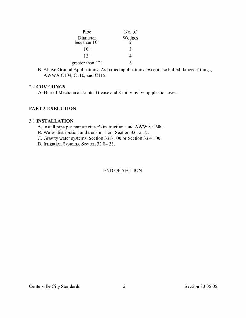
Centerville City Standards 2 Section 33 05 05
Pipe No. ofDiameter Wedges
less than 10" 2
10" 3
12" 4
greater than 12" 6
B. Above Ground Applications: As buried applications, except use bolted flanged fittings,AWWA C104, C110, and C115.
2.2 COVERINGS A. Buried Mechanical Joints: Grease and 8 mil vinyl wrap plastic cover.
PART 3 EXECUTION
3.1 INSTALLATION A. Install pipe per manufacturer's instructions and AWWA C600.
B. Water distribution and transmission, Section 33 12 19. C. Gravity water systems, Section 33 31 00 or Section 33 41 00. D. Irrigation Systems, Section 32 84 23.
END OF SECTION
Centerville City Standards 1 Section 33 05 06
SECTION 33 05 06
POLYETHYLENE PIPE
PART 1 GENERAL
1.1 SECTION INCLUDES A. Polyethylene pipe, couplings, fittings and joint materials. B. Related work includes but is not limited to,
1. Excavation, Section 31 23 16. 2. Trench backfill, Section 33 05 20 . 3. Landscape restoration, Section 32 92 00 or Section 32 93 13. 4. Pavement restoration, Section 33 05 25.
1.2 REFERENCES
A. AASHTO M 252: Standard Specification for Corrugated Polyethylene Drainage Pipe.
B. AASHTO M-294: Standard Specification for Corrugated Polyethylene Drainage Pipe300-1200 mm Diameter.
C. AASHTO MP7-97: Standard specification for Corrugated Polyethylene Pipe – 1350 and1500 mm Diameter.
D. ASME B1.1: Unified Inch Screw Threads (UN and UNR Thread Form), Supplement.
E. ASTM A 307: Standard Specification for Carbon Steel Bolts and Studs, 60,000 psiTensile Strength.
F. ASTM D 2239: Standard Specification for Polyethylene (PE) Plastic Pipe (SDR-PR)Based on Controlled Inside Diameter.
G. ASTM D 2321: Standard Practice for Underground Installation of FlexibleThermoplastic Sewer Pipe.
H. ASTM D 2657: Standard Recommended Practice for Heat Joining of ThermoplasticPipe and Fittings.
I. ASTM D 2774: Standard Recommended Practice for Underground Installation ofThermoplastic Pressure Piping.
J. ASTM D 3261: Standard Specification for Butt Heat Fusion Polyethylene (PE) PlasticFittings for Polyethylene (PE) Plastic Pipe and Tubing.
K. ASTM D 3350: Standard Specification for Polyethylene Plastics Pipe and FittingsMaterials.
L. ASTM F 477: Standard Specification for Elastomeric Seals (Gaskets) for JoiningPlastic Pipe.
M. ASTM F 1055: Standard Specification for Electofusion Type Polyethylene Fittings forOutside Diameter Controlled Polyethylene Pipe and Tubing.
Centerville City Standards 2 Section 33 05 06
1.3 DEFINITIONS
A. Standard Dimension Ratio (SDR): Average diameter of pipe divided by the minimumwall thickness. The diameter may be either inside or outside measurement dependingupon which standard is referenced.
B. Code Designation: A rating system by the Plastic Pipe Institute for smooth wallpolyethylene pipe materials. The designation PE 3408 designates the type of plastic pipe(PE), the grade (34), and the hydrostatic design stress measured in units of 100 psi (08)at 23 deg C.
PART 2 PRODUCTS
2.1 SMOOTH WALL PIPE SYSTEMS
A. Material: PE 3408 per ASTM D 2239 with a minimum cellclassification of 345434C per ASTM D 3350.
B. Pipe: Smooth wall inside and out with an SDR or working pressure rating indicated oraccepted by City Engineer. Exterior markings as follows.
1. ASTM Standard Number. 2. Pipe Size. 3. Class and profile number. 4. Production code. 5. Standard dimension ratio.
C. Fittings:
1. Resin same as pipe. 2. Working pressure same or greater than pipe.
D. Joints:
1. Thermally welded butt fusion, ASTM D 3261. 2. Flanged, ASTM D 2657. 3. Ultra high molecular weight electo-fusion tape with a polyethylene coupler meeting
ASTM F 1055 requirements.
2.2 CORRUGATED WALL PIPE SYSTEMS
A. Material: Polyethylene, ASTM D 3350 with a cell class as required in AASHTO M252, AASHTO M 294 or AASHTO MP7-97
B. Pipe: Type S or D unless specified otherwise. Corrugations may be either annular orhelical.
Type Description
C Circular pipe with a corrugated surface inside and out.
Centerville City Standards 3 Section 33 05 06
CP Type C pipe with perforations
S Circular pipe with an outer corrugated wall and a smooth interwall
SP Type S pipe with perforations
D Circular pipe with a corrugated wall sandwiched between asmooth outer wall and a smooth inner wall.
C. Fittings:
1. Blow molded with cell class 335420C, ASTM D 3350. 2. Rotational molded with cell class 213320C, ASTM D 3350. 3. Shop or field remanufactured of the same material as the pipe
D. Joints:
1. Bell and spigot with gaskets, ASTM F 477. Foam type weather stripping not allowed. 2. Split corrugated couplings with plastic or stainless steel ties and leak resistant
neoprene gasket.
2.3 NUTS AND BOLTS
A. Carbon steel machined heavy hex heads, Class 2 fit, ASTM A 307; Grade B, threads,ASME B1.1.
PART 3 EXECUTION
3.1 INSTALLATION
A. Install pipe as per manufacturer's instructions, ASTM D 2321 or ASTM D 2774.
B. Water distribution and transmission, Section 33 12 19.
C. Gravity water systems, Section 33 31 00 or Section 33 41 00.
D. Irrigation Systems, Section 32 84 23.
E. Tape wrap steel materials for protection against corrosion after piping installation.
END OF SECTION
Centerville City Standards 1 Section 33 05 07
SECTION 33 05 07
POLYVINYL CHLORIDE PIPE
PART 1 GENERAL
1.1 SECTION INCLUDES A. Polyvinyl chloride pipe, couplings, fittings and joint materials. B. Related work includes but is not limited to,
1. Excavation, Section 31 23 16. 2. Trench backfill, Section 33 05 20 . 3. Landscape restoration, Section 32 92 00 or Section 32 93 13. 4. Pavement restoration, Section 33 05 25.
1.2 REFERENCES
A. ASTM D 1784: Standard Specification for Rigid Poly (Vinyl Chloride) (PVC)Compounds and Chlorinated Poly (Vinyl Chloride) (CPVC) Compounds.
B. ASTM D 2241: Standard Specification for Poly (Vinyl Chloride) (PVC) Pressure RatedPipe (SDR -Series).
C. ASTM D 2321: Standard Practice for Underground Installation of FlexibleThermoplastic Sewer Pipe.
D. ASTM D 2412: Standard Test Method for Determination of External LoadingCharacteristics of Plastic Pipe by Parallel-Plate Loading.
E. ASTM D 2564: Standard Specification for Solvent Cement for Poly(VinylChloride) (PVC) Plastic Pipe and Fittings.
F. ASTM D 2729: Standard Specification for Poly(Vinyl Chloride) (PVC) Sewer Pipe andFittings.
G. ASTM D 2774: Standard Recommended Practice for Underground Installation ofThermoplastic Pressure Piping.
H. ASTM D 2855: Standard Practice for Making Solvent Cemented Joints with Poly(VinylChloride) (PVC) Pipe and Fittings.
I. ASTM D 3034: Standard Specification for Type PSM Poly(Vinyl Chloride) (PVC)Sewer Pipe and Fittings.
J. ASTM D 3139: Standard Specification for Joints for Plastic Pressure Pipes UsingFlexible Elastomeric Seals.
K. ASTM D 3212: Standard Specification for Joints for Drain and Sewer Plastic PipesUsing Flexible Elastomeric Seals.
L. ASTM F 656: Standard Specification for Primers for Use in Solvent Cement Joints ofPoly(Vinyl Chloride) (PVC) Plastic Pipe and Fittings.
Centerville City Standards 2 Section 33 05 07
M. ASTM F 679: Standard Specification for Poly(Vinyl Chloride) (PVC) Large-DiameterPlastic Gravity Sewer Pipe and Fittings.
N. ASTM F 949: Standard Specification for Poly(vinyl Chloride) (PVC) Corrugated sewerPipe with a Smooth Interior and Fittings.
O. AWWA C900: AWWA Standard for Polyvinyl Chloride (PVC) Pressure Pipe, 4 In.Through 12 In., for Water Distribution.
1.3 DEFINITIONS
A. Standard Dimension Ratio (SDR): Outside diameter of pipe divided by wall thickness.
PART 2 PRODUCTS
2.1 GRAVITY PIPE SYSTEMS
A. Pipe:
1. Solid smooth wall, 4 to 15 inch diameter, ASTM D 3034. 2. 18 to 27 inch diameter, ASTM F 679. 3. 4 to 10 inches diameter corrugated wall with a smooth interior, ASTM F 949.
B. Fittings: ASTM D 1784.
C. Stiffness: 50 psi minimum when measured at 5 percent deflection, ASTM D 2412.
D. Additives and Fillers: Not to exceed 10 parts by weight; 100 parts of resin in thecompound.
E. Joints: Bell and spigot with flexible elastomeric seals, ASTM D 3212.
F. Flattening: No visual evidence of splitting, cracking, or breaking when flattened to 60percent deflection, ASTM D 2412.
2.2 PRESSURE PIPE SYSTEMS A. Pipe: Conform to AWWA C900 except use outside diameters defined by ductile iron
pipe sizes. Dimensions, class, SDR, and tolerances per ASTM D 2241. B. Compounds: Type 1, Grade 1, Class 12454A, ASTM D 1784. C. Joints:
1. Bell and spigot with flexible elastomeric seals, ASTM D 3139. Use non-toxiclubricant.
2. Solvent weld, ASTM D 2564.
2.3 PERFORATED PIPE SYSTEMS A. Pipe: Refer to gravity pipe products above.
B. Perforations: ASTM D 2729.
C. Joints: Push-on, solvent weld or other.
Centerville City Standards 3 Section 33 05 07
2.4 SOLVENT WELDS
A. Primer, ASTM F 656.
B. Glue, ASTM D 2564.
PART 3 EXECUTION
3.1 INSTALLATION
A. Install pipe per manufacturer's instructions, ASTM D 2321 for gravity systems, AWWAC900 or ASTM D 2774 for pressure systems, And ASTM D 2855 for undergroundIrrigation Systems.
B. Water distribution and transmission, Section 33 12 19.
C. Gravity water systems, Section 33 31 00 or Section 33 41 00.
D. Irrigation System, Section 32 84 23.
END OF SECTION
Centerville City Standards 1 Section 33 05 08
SECTION 33 05 08
PRE-STRESSED CONCRETE PIPE
PART 1 GENERAL
1.1 SECTION INCLUDES
A. Concrete cylinder pipe in sizes 12 inches through 72 inches composed of the following.
1. A welded steel cylinder.
2. Steel joint rings welded to the cylinder. 3. A centrifugally spun cement-mortar lining. 4. A pretensioned rod wrapping helically wound around the steel cylinder under
measured tension. 5. An exterior cement-mortar coating.
B. Couplings, fittings, and joint materials.
C. Related work includes but is not limited to,
1. Excavation, Section 31 23 16. 2. Trench backfill, Section 33 05 20 . 3. Landscape restoration, Section 32 92 00 or Section 32 93 13. 4. Pavement restoration, Section 33 05 25.
1.2 REFERENCES
A. AISI Steel Designation No. 1012: Standard Nonsilverized Carbon Steel.
B. ASTM A 283: Standard Specification for Low and Intermediate Tensile Strength CarbonSteel Plates.
C. ASTM A 370: Standard Test Methods and Definitions for Mechanical Testing of SteelProducts.
D. ASTM A 569: Standard Specification for Steel, Carbon (0.15 Maximum, Percent), Hot-Rolled Sheet and Strip, Commercial Quality.
E. ASTM A 570: Standard Specification for Steel, Sheet and Strip, Carbon, Hot-Rolled,Structural Quality.
F. ASTM A 611: Standard Specification for Steel, Sheet, Carbon, Cold-Rolled,Structural Quality.
G. ASTM A 615: Standard Specification for Deformed and Plain Billet-Steel Bars forConcrete Reinforcement.
H. ASTM C 33: Standard Specifications for Concrete Aggregates.
I. ASTM C 150: Standard Specification for Portland Cement.
J. AWWA C200: AWWA Standard for Steel Water Pipe 6 In. and Larger.
Centerville City Standards 2 Section 33 05 08
K. AWWA C208: AWWA Standard for Dimensions for Fabricated Steel Water Pipe Fittings.L. AWWA C303: AWWA Standard for Reinforced Concrete Pressure Pipe, Steel
Cylinder Type, Pretensioned, for Water and Other Liquids.
1.3 SUBMITTALS
A. Design Summary: Prior to any fabrication, submit a design summary for each size andclass of pipe together with line layout drawings or line schedules that show the location ofeach section of pipe and each special fitting to be furnished.
1.4 DELIVERY, STORAGE AND HANDLING
A. Attach end covers to pipe stored either in the yard or in the field. Reject injurious dryingout of concrete.
B. Stalls: Remain in place during storage.
C. Gaskets: Store in cool, well ventilated place and protect from direct sunlight.
PART 2 PRODUCTS
2.1 STEEL CYLINDER
A. Fabricated from either.
1. Hot-rolled carbon steel sheets: ASTM A 570, Grade C, or ASTM A 611, or ASTM A569 except that the maximum carbon content may be 0.25 percent and a minimumyield strength of 33,000 psi.
2. Plates: ASTM A 283, Grade D. 3. Gauge of cylinder steel.
Pipe Size Gauge
12” to 16” 1618” to 21” 1524” to 33” 1436” to 51” 1254” to 57” 1160” to 63” 1066” to 69” 9
72” 8
B. Seams: Fabricate sheets or plates into cylinders with longitudinal or helical seams. Wherelongitudinal seams are used, fabricate in courses, which may consist of two or moresheets or plates. Produce welds with a tensile strength at least equal to the specifiedminimum tensile strength of the sheet or plate. Cut test specimens from the cylinder andtest per ASTM A 370 when indicated.
C. Specified Diameter: The inside diameter of the concrete section.
Centerville City Standards 3 Section 33 05 08
D. Circumference of Steel Cylinders: Not to deviate from the design value by more than+3/16 inch for pipe sizes 16 inches and smaller or more than +1/4 inch for larger sizes.
2.2 STEEL CYLINDER AND ROD AREA A. Total Cross-Section Area (cylinder plus rod reinforcement): Computed on the basis of a
maximum stress of 16,500 psi, in the steel at the design pressure with no allowance fortensile strength of the concrete.
B. Rod Wrap: Not less than 7/32 inch diameter.
C. Maximum Center to Center Spacing Between Rods: No greater than 1-1/2 inches withcylinder thickness less than 14 gage nor greater than 2 inches with cylinder thickness 14gage and heavier.
D. Minimum Cross-Section Area of Rod Reinforcement per Lineal Foot of Pipe:Numerically equal to at least 1 percent of the nominal inside diameter of the pipe ininches.
E. Minimum Center to Center Spacing Between Rods: No closer than 2 rod diameters.
F. Cross-Sectional Area of the Rod Reinforcement: Not to exceed 60 percent of thetotal required area of steel.
2.3 ROD WRAPPINGS
A. Rod Reinforcement: ASTM A 615, Grade 40, except:
1. Bars: Plain round bars except the requirements of Sec. 6, 7 and 14.3 shall not apply. 2. Intermediate Diameter Bars: Meet the requirements for the next smaller bar number
designation. 3. Bars of Diameter Less Than No. 3: Meet the requirements for No. 3 bar.
B. Helically wind rods and space equally along the length of the cylinder and continueover the cylindrical portion of the bell ring.
C. Use a suitable device for stressing, measuring, and visibly indicating the tension in therod during the winding operation. Hold the tension within 110 to 125 percent of thedifference between the specified minimum yield strengths of the cylinder and rod.Continue the rod wrapping from end to end of the cylinder and weld to the joint rings.Lap weld the welded splices in the rod for a distance of 4 rod diameters or butt weld insuch a manner that the joint develops a tensile strength at least equal to the specifiedminimum strength of the rod. Test each butt welding to the stress of 25,000 psi tension.
2.4 JOINTS
A. Steel Joint Rings: Bell and spigot rubber gasket type, self-centering without the gasketsupporting the weight of the pipe and the steel conforming to the requirements ofAISI Steel Designation No. 1012.
B. Spigot Rings: Fabricated from a specially rolled section which includes a gasket groove.
Centerville City Standards 4 Section 33 05 08
Proportion the groove that, upon proper closure of the joint, the gasket will be suitablecompressed and will effect a watertight seal which provides for expansion, contractionand deflection.
C. Bell Ring Thickness Plus Rod Reinforcement Over the Bell: Provide a total cross-sectional area not less than 1/3 greater than that furnished for an equivalent length alongthe barrel of the pipe.
D. Sizing: Size both the bell and spigot rings to the same design diameter by expanding therings beyond the elastic limit of the steel.
E. Tolerances:
1. Minimum bell ring thickness: U.S. standard 10 gage for pipe sizes 12 inches through16 inches and 3/16 inch for larger sizes.
2. Circumference of the inside bell ring contact surface: Not to exceed the circumferenceof the outside spigot ring contact surface by more than 3/16 inch.
2.5 TESTING STEEL CYLINDERS
A. After each cylinder is completed, but prior to lining or coating, test hydrostatically to aminimum hydrostatic pressure which develops a circumferential tensile stress of notless than 20,000 psi and not more than 25,000 psi. Reweld cylinders that show anyLeakage under test at the points of Leakage and subject them to another hydrostatic test.Continue procedure until completely watertight under the required test pressure.
2.6 RUBBER GASKETS
A. Shape: Circular cross-section.
B. Gasket Compounds: Conform to the requirements of AWWA C200 consisting of firstgrade natural rubber, synthetic rubber, or a suitable combination thereof. Form and curein such a manner as to be dense and homogenous with a smooth surface free fromblisters, pits, and other imperfections.
2.7 CEMENT
A. Cement: Type II, ASTM C 150 unless indicated otherwise.
2.8 AGGREGATES
A. Sand for Cement-Mortar: "Fine Aggregate", ASTM C 33, except that the gradation maybe modified to provide a lining of optimum density.
2.9 CEMENT-MORTAR LINING
A. Cement-Mortar: One part cement to not more than 3 parts fine aggregate by weight.Control water content to obtain dense, workable, durable mortar.
Centerville City Standards 5 Section 33 05 08
B. Spin the lining in the cylinder to obtain a nominal thickness of 1/2 inch for pipe sizes 12inches through 16 inches and to a nominal thickness of 3/4 inch for pipe sizes 18 inchesand larger. Use gage rings at the ends of the pipe to control the thickness. Take adequatemeasures to limit the deviation from the mean diameter of the cylinder, at any section, toa maximum of 1/2 percent of the mean diameter. Where required, place external rounduprings around the cylinder prior to the spinning to ensure roundness of the cylinder anduniformity of lining thickness. After the mortar has been placed in the cylinder, revolve ata speed that will cause the cement-mortar to level out to a uniform thickness throughoutthe cylinder. Continue the spinning until the lining is thoroughly compacted and surpluswater removed, and the finished lining is smooth and uniform throughout.
C. Moist cure the lining for a minimum period of 24 hours after spinning before wrappingthe cylinder with rod. This may be accomplished by tightly sealing the ends of thecylinder with a waterproof membrane to retain the moisture in the mortar. Vaporcuring may be used in lieu of or in combination with moist curing on a time ratio basisof one hour vapor curing to 4 hours moist curing. Transport, support, and cure in amanner to prevent damage to the lining.
D. Lining Thickness Tolerance: Not more than plus or minus 25 percent from thespecified nominal thickness.
2.10 EXTERIOR COATING
A. Cement-Mortar for Coating: Ratio of 1 part of cement to not more than 3 parts of fineaggregate, by weight. Control the water content to obtain a dense, workable, durablemortar. Rebound may be reclaimed and used as aggregate.
B. Apply by mechanical means producing a dense, uniform finished coating adheringtightly to the pipe. Provide a minimum nominal coating applied over the cylinder of 3/4inch over the rod wrap.
C. Cement Slurry Coating: One bag of cement to not more than 10 gallons of waterapplied concurrent with the coating application to coat the steel assembly surface underthe rod and the mortar-coating leading edge.
D. Suitably support the pipe during handling and curing to prevent damage to the liningand coating.
2.11 CURING COMPLETED PIPE
A. Moist cure the lining for a minimum period of 6 days. Vapor curing may be used in lieuof or in combination with moist curing on a time ratio basis of one hour vapor curing to4 hours moist curing.
B. Protect the mortar lining from temperatures below 40 deg. F. during the application.
2.12 JOINT LENGTHS
Centerville City Standards 6 Section 33 05 08
A. 40 feet except where shorter lengths are required for fittings, curves, or closures.
2.13 BENDS AND SPECIFIC FITTINGS
A. Fabricated short radius bends or special fittings such as wyes, tees and crosses frompreviously tested steel cylinders, AWWA C208. Fabricate bends or special fittings atleast equal in strength to the abutting pipe sections and mortar line and coat afterfabrication. Obtain approval of the design prior to fabrication.
B. Test all seams of bends or special fittings, except those seams previously tested ascylinders. Test seams by the air soap method or by the dye-check method. Repair anyleaks by welding and retest the seam and recoat if required.
2.14 OUTLETS
A. Fabricate outlets into the wall of the pipe, prior to testing, for blow-offs, branches, airvalves, and access manholes. Provide cast or fabricated steel fittings of suitable designand securely weld to the cylinder before being coated. Reinforce the pipe cylinder, asnecessary, for the required opening. Obtain approval of the design of such outlets priorto fabrication.
2.15 WELDED JOINTS
A. Where welded joints are shown on the Drawings, the rubber gasketed joint may bewelded by inserting a filler rod under the flare of the bell and welding in place to thebell ring and to the spigot ring, or special joints for field welding may be furnished.
2.16 BEVELED ENDS
A. Where curves are required which have a shorter radius than can be obtained byunsymmetrical closure of the joint, sections of pipe may be furnished with beveled ends.An end of beveled pipe may have a maximum bevel of 5 degrees measured from a planeperpendicular to the axis of the pipe. The long point of the bevel shall be so marked onthe pipe.
2.17 SOURCE QUALITY CONTROL
A. Refer to AWWA C303.
PART 3 EXECUTION
3.1 INSTALLATION
A. Install pipe and fittings per manufacturer's recommendations and Section 33 12 19. Useslings or pipe manufacturer approved lifting devices.
Centerville City Standards 7 Section 33 05 08
B. Lay the pipe to curved alignment by means of unsymmetrical closure of the joints.
1. Use a joint deflection of up to 3/4 inch for pipe sizes 12 inches through 24 inches. 2. Use a joint deflection of up to 1 inch for pipe sizes 27 inches and larger.
C. Where curves are required which have shorter radius than can be obtained byunsymmetrical closure of the joint, furnish sections of pipe with beveled ends. The endof a beveled pipe may have a maximum bevel of 5 degrees measured from a planeperpendicular to the axis of the pipe. Mark the long point of the bevel on the pipe.
D. Joints to be grouted inside and outside as per manufacturer'srecommendations.
END OF SECTION
Centerville City Standards 1 Section 33 05 10
SECTION 33 05 10
VITRIFIED CLAY PIPE
PART 1 GENERAL
1.1 SECTION INCLUDES A. Vitrified clay pipe, fittings, and joint materials. B. Related work includes but is not limited to,
1. Excavation, Section 31 23 16. 2. Trench backfill, Section 33 05 20 . 3. Landscape restoration, Section 32 92 00 or Section 32 93 13. 4. Pavement restoration, Section 33 05 25.
1.2 REFERENCES
A. ASTM C 12: Standard Recommended Practice for Installing Vitrified Clay Pipe Lines.
B. ASTM C 301: Standard Methods of Testing Vitrified Clay Pipe.
C. ASTM C 425: Standard Specification for Compression Joints for Vitrified Clay Pipeand Fittings.
D. ASTM C 700: Standard Specification for Vitrified Clay Pipe, Extra Strength, StandardStrength, and Perforated.
PART 2 PRODUCTS
2.1 PIPE
A. Vitrified clay, extra strength, ASTM C 700.
B. Furnish branches with connections completed and fastened to the barrel of the pipe in theprocess of manufacture.
2.2 JOINTS
A. Bell and spigot type joints, ASTM C 425.
B. Compression couplings for plain end pipe
2.3 SOURCE QUALITY CONTROL
A. Loading tests and quantities tested, ASTM C 301. Pipe shall withstand the followingminimum loads for a 3 edge bearing test.
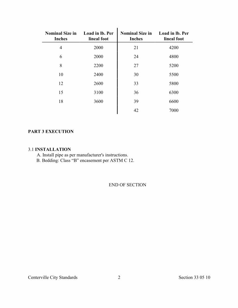
Centerville City Standards 2 Section 33 05 10
Nominal Size inInches
Load in lb. Perlineal foot
Nominal Size inInches
Load in lb. Perlineal foot
4 2000 21 4200
6 2000 24 4800
8 2200 27 5200
10 2400 30 5500
12 2600 33 5800
15 3100 36 6300
18 3600 39 6600
42 7000
PART 3 EXECUTION
3.1 INSTALLATION A. Install pipe as per manufacturer's instructions. B. Bedding: Class “B” encasement per ASTM C 12.
END OF SECTION
Centerville City Standards 1 Section 33 05 14
SECTION 33 05 14
UTILITY GRADE ADJUSTMENT
PART 1 GENERAL
1.1 SECTION INCLUDES A. Raise, lower, or change slope of Street Fixtures. B. Install Cover Collars.
C. This section is NOT APPLICABLE to raising and lowering Street Fixtures thatwithstand internal pressure.
1.2 DEFINITIONS
A. Box: A structure such as a valve box, meter box, monument box, fire hydrant box,electrical pull box, cleanout box or other like structure not intended for human entry.
B. Cover Collar: A concrete filled annular space between metal frames and the adjacentPavement structural section.
C. Extension Ring: A concrete or metal ring used to adjust surface elevations and surfacecross slopes of Street Fixture covers. Metal rings are used between metal frames andmetal covers or grates. Concrete rings are used below metal frames or in the concretestructure below.
D. Manhole: A structure designed to permit human entry and working space inside and toconfine and control the flow of pipe-conveyed fluids. These structures are collectively referred to as manholes regardless of composition,design, type or depth.
E. Street Fixture: The top of existing structures such as but not limited to Manholes, catchbasin, sumps, inlets, valve boxes, meter boxes, monument boxes, and similar structurein a thoroughfare surface.
F. Vault: A structure intended for human entry containingelectrical/telephone facilities or other like utilities.
PART 2 PRODUCTS
2.1 PAVEMENT
A. Asphalt Concrete: AC-20-DM-1/2, Section 32 12 05.
B. Cast-in-place Concrete: Class 4000, Section 03 30 04.
2.2 GROUT
Centerville City Standards 2 Section 33 05 14
A. Hydraulic cement, Section 03 61 00.
2.3 EXTENSION RINGS A. Metal: Cast iron or steel, Section 05 56 00. B. Cast-in-place Concrete: Class 4000, Section 03 30 04.
PART 3 EXECUTION
3.1 PREPARATION
A. Determine condition of existing incidental structure. Any item not reported damagedprior to construction shall be considered unbroken and must be replaced.
B. Provide invert cover over pipe in cleanout box to prevent gravel, concrete, ordebris from entering pipeline.
C. Unless indicated otherwise, arrange for utility companies to adjust their own structures.
D. Coordinate all adjustments with requirements of affected utility company.
3.2 ADJUST STRUCTURE TO GRADE
A. Restrict excavation around the structure to a minimum area.
B. At the completion of the structure adjustment, backfill the void around the structure andcompact before paving or landscaping.
C. Apply mortar to inside and outside of concrete grade rings used to make adjustments.
D. If the cone is cracked during construction, restack the Manhole with shorter Manholesections and install a new cone.
3.3 ADJUST COVER IN PAVEMENT SURFACE
A. Method A -Metal Extension Rings:
1. Use rings that lock together. 2. Set frame at desired elevation and cross-slope. 3. Seal joints between Pavement and ring, Section 32 01 17.
B. Method B – Concrete Extension Rings:
1. Place concrete grade rings under frame or in structure riser shaft. 2. Set frame at desired elevation and cross-slope. 3. Provide 100 percent concrete support under frame. Do not use wood, bricks, concrete
fragments, blocks or particles as support. 4. Grout seams between concrete rings and between frame and concrete rings.
C. Method C – Place Concrete: 1. Set frame at desired elevation and cross-slope. 2. Place concrete and provide 100 percent concrete support under frame.
Centerville City Standards 3 Section 33 05 14
D. Method D – Concrete Deck:
1. Remove existing concrete deck. 2. Reset steel rebar. 3. Set frame to grade, set forms. 4. Pour concrete. Provide complete concrete support under Street Fixture.
3.4 INSTALLING COVER COLLAR
A. Open an annular space between pavement and Street Fixture cover. Unless indicatedotherwise, provide 12 inches of annular space.
B. Set concrete collar to 1/4 inch minimum to 1/2 inch maximum below asphalt concretepavement surface and 1/4 inch below portland cement concrete pavement surface.
C. Trowel finish, Section 03 35 00.
3.5 PAVEMENT SURFACE RESTORATION
A. In new streets or overlays, adjust Street Fixture cover after bituminous paving iscomplete.
B. Pavement restoration, Section 33 05 25.
END OF SECTION
Centerville City Standards 1 Section 33 05 20
SECTION 33 05 20
BACKFILLING TRENCHES
PART 1 GENERAL
1.1 SECTION INCLUDES A. Trench backfill materials. B. Trench backfilling requirements. C. Surface restoration requirements.
1.2 DEFINITIONS
A. Bedding: That surface of the Excavation or portion of the Pipe Zone below the pipe.
B. Pipe Zone: That zone in a backfilling operation which supports, and surrounds the pipebarrel, and extends to 1 foot above the top of the pipe barrel.
1.3 SUBMITTALS
A. Submit maximum laboratory dry density and optimum laboratory moisture contentfor:
1. Subgrade material, and 2. Each type of fill to be used.
B. Upon City Engineer's request, submit a written quality control Inspections and testingreport describing source and field quality control activities performed by Devleoper andits Suppliers.
1.4 QUALITY ASSURANCE
A. Do not change material sources, or aggregate without City Engineer's knowledge.
B. Reject backfill material that does not comply with requirements specified in this section.
1.5 STORAGE AND PROTECTION
A. Storage:
1. Safely stockpile backfill materials. 2. Separate differing materials, prevent mixing, and maintain optimum moisture content
of backfill materials. B. Protection:
1. During installation or repair, plug end of pipe or fitting except when installing nextsection of pipe or fitting.
2. Avoid displacement of and injury to Work while compacting or operating equipment. 3. Movement of construction machinery over Work at any stage of
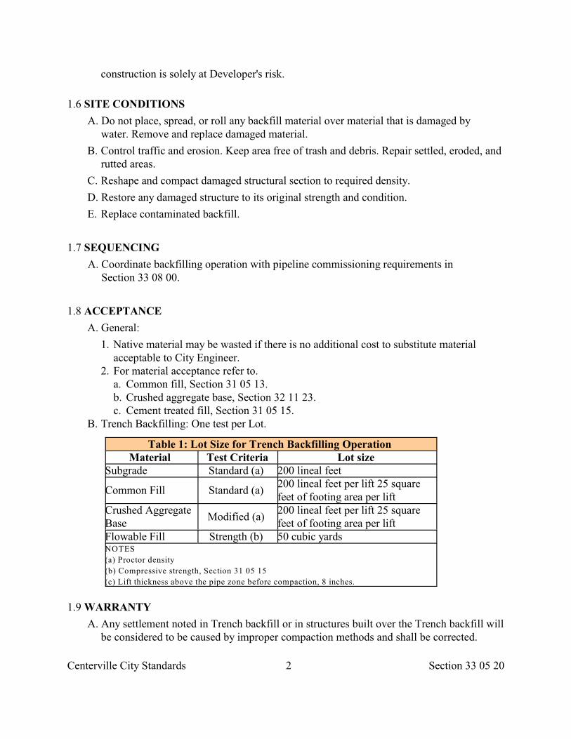
Centerville City Standards 2 Section 33 05 20
construction is solely at Developer's risk.
1.6 SITE CONDITIONS
A. Do not place, spread, or roll any backfill material over material that is damaged bywater. Remove and replace damaged material.
B. Control traffic and erosion. Keep area free of trash and debris. Repair settled, eroded, andrutted areas.
C. Reshape and compact damaged structural section to required density.
D. Restore any damaged structure to its original strength and condition.
E. Replace contaminated backfill.
1.7 SEQUENCING
A. Coordinate backfilling operation with pipeline commissioning requirements inSection 33 08 00.
1.8 ACCEPTANCE
A. General:
1. Native material may be wasted if there is no additional cost to substitute materialacceptable to City Engineer.
2. For material acceptance refer to. a. Common fill, Section 31 05 13. b. Crushed aggregate base, Section 32 11 23. c. Cement treated fill, Section 31 05 15.
B. Trench Backfilling: One test per Lot.
Table 1: Lot Size for Trench Backfilling Operation Material Test Criteria Lot size
Subgrade Standard (a) 200 lineal feet
Common Fill Standard (a) 200 lineal feet per lift 25 squarefeet of footing area per lift
Crushed AggregateBase
Modified (a) 200 lineal feet per lift 25 squarefeet of footing area per lift
Flowable Fill Strength (b) 50 cubic yards NOTES
(a) Proctor density
(b) Compressive strength, Section 31 05 15
(c) Lift thickness above the pipe zone before compaction, 8 inches.
1.9 WARRANTY
A. Any settlement noted in Trench backfill or in structures built over the Trench backfill willbe considered to be caused by improper compaction methods and shall be corrected.
Centerville City Standards 3 Section 33 05 20
B. Restore structures damaged by settlement.
PART 2 PRODUCTS
2.1 BACKFILL MATERIALS A. Common fill, Section 31 05 13. B. Crushed aggregate base, Section 32 11 23. C. Cement treated fill, Section 31 05 15. D. Slag or asphalt bearing material not allowed.
2.2 ACCESSORIES
A. Water: Make arrangements for sources of water during construction and makearrangements for delivery of water to site. Comply with local Laws and Regulations whensecuring water from water utility company.
B. Geotextile Fabric: Section 31 05 19.
C. Identification Tape: Permanent, bright-colored, continuous-printed magnetic plastic tape,intended for direct-burial service; not less than 6 inches wide by 4 mils thick. The tapeshall read "CAUTION: BURIED INSTALLATION BELOW". Color of tape asfollows.
1. Red: Electric power lines, cables, conduit and lighting cables 2. Yellow: Gas, oil, steam, Petroleum or gaseous materials 3. Orange: Communications, alarm, signal, cables or conduits 4. Blue: Potable water 5. Purple: Reclaimed Water, irrigation and slurry lines 6. Green: Sewer and storm drain lines
PART 3 EXECUTION
3.1 PREPARATION
A. Verify backfill material meets gradation requirements, foundation walls are braced tosupport surcharge forces imposed by backfilling operations, areas to be backfilled arefree of debris, snow, ice or water, and Trench bottom is not frozen.
B. If Subgrade is not readily compactable secure written authorization for extra excavationand backfill; Section 31 23 16.
C. Avoid injuring and displacement of pipe and structures whilecompacting soil or operating equipment next to pipeline.
D. Place geotextile fabrics; Section 31 05 19.
3.2 GENERAL BACKFILLING REQUIREMENTS A. Protect Subgrade from desiccation, flooding and freezing.
Centerville City Standards 4 Section 33 05 20
B. Do not damage corrosion protection on pipe. C. Repair or replace damaged pipe.
D. Withdraw sheathing, Shoring, piles, and similar supports as backfilling progresses. Backfilland compact all holes left by removals.
E. Provide sufficient water quality facilities to protect downstream fish and wildlife, and tomeet State water quality requirements.
F. Water settling of Trench backfill is not permitted. "Jetting" of Trench backfill isprohibited.
3.3 PIPE ZONE
A. Maintain uniform foundation along barrel of pipe with sufficient relief for jointconnections.
B. Use backfill materials meeting pipe manufacturer's recommendations. Maximum backfillparticle size is 3/4 inch for plastic pipe.
C. Do not permit free fall of backfill material which may damage pipe, pipe finish, or pipealignment.
D. Except where piping must remain exposed for tests, fill Pipe Zone as soon as possible.
3.4 TRENCH ABOVE PIPE ZONE.
A. Maximum lift thickness before compaction is 8 inches.
B. Fill unauthorized Excavations with material acceptable to City Engineer.
C. Do not damage adjacent structures or service lines.
D. Install continuous plastic line marker directly over buried lines 18 inches below finishedgrade.
3.5 MODIFIED BACKFILL LAYER METHOD
A. At discretion of Developer, backfill may be placed in thicker layers than indicated abovesubject to the following provisions.
1. Developer proves the ability of proposed method to achieve specified averagecompaction density.
2. City Engineer, on the basis of test results, approves the system in writing. B. Should Developer find it necessary to change the method or any part of it, including the
source of material, or the rate of placing the material, obtain approval of City Eningeer,who may require a further trial area.
C. If testing shows a previously approved system is no longer producing the required degree ofcompaction, make changes to comply.
D. Where vibration effects are creating environmental problems, make changes toeliminate problems.
Centerville City Standards 5 Section 33 05 20
3.6 COMPACTION A. Compact backfill.
1. A-1 soils: 95 percent or greater of a Modified Proctor Density. 2. Other soils: 95 percent or greater of a Standard Proctor Density.
3.7 COMPRESSIVE STRENGTH
A. Where a flowable fill is used, provide compressive strength indicated in Section 31 05 15.Use fill which flows easily and vibration is not required.
3.8 SURFACE RESTORATION
A. Provide temporary paved surfaces where Trenches pass through roadways,Driveways or sidewalks.
B. Restore paved surfaces; Section 33 05 25.
C. Finish landscaped surfaces with grass, Section 32 92 00 or with other ground cover,Section 32 93 13.
3.9 CLEANING
A. Remove stockpiles from the site. Grade site surface to prevent free standing surfacewater.
B. Leave borrow areas clean and neat.
END OF SECTION
Centerville City Standards 1 Section 33 05 23
SECTION 33 05 23
TRENCHLESS UTILITY INSTALLATION
PART 1 GENERAL
1.1 SECTION INCLUDES A. Boring or jacking pipe or box culvert.
1.2 REFERENCES
A. ASTM A 53: Standard Specification for Pipe, Steel, Black and Hot-Dipped,Zinc-Coated, Welded and Seamless.
1.3 SUBMITTALS
A. Details of jacking pit bracing, casing or conduit, and jacking head to be used.
B. Dimensions and support of pilot tunnel (if used).
C. Details of steel rails in pilot tunnel (if used), including true line and grade.
D. Copy of applicable permits from agency having jurisdiction.
1.4 PERFORMANCE REQUIREMENTS
A. Jack conduit to line and grade indicated. Modify the jacking operation to correct anydeviation. Correct any misalignment in line or grade.
B. The methods and equipment used in jacking casing or conduit are Developer'schoice.
C. Use workers experienced in jacking operations.
PART 2 PRODUCTS
2.1 STEEL CASING
A. ASTM A 53, Grade B steel pipe for jacking operations, minimum wall thickness of0.375 inch, minimum yield stress of 42,000 psi. Use a casing with a diameter equal tothe outside bell diameter of the pipe plus a minimum 4 inches.
B. Fillet weld joints continuous around casing and reinforce joints to withstandjacking operations.
2.2 CONCRETE PIPE
A. Section 33 05 02. When concrete pipe is to be jacked, use a pipe section designed to
Centerville City Standards 2 Section 33 05 23
support the superimposed loads and the loads that may be placed upon the pipe duringjacking operations. Use pipe sections that have a watertight joint.
2.3 SOIL CEMENT A. Portland cement treated fill, Section 31 05 15. B. Grout: Cement, Section 03 61 00.
PART 3 EXECUTION
3.1 PREPARATION A. Coordinate utility locations, Section 01 31 13.
3.2 JACKING PROCEDURE
A. When casing is to be jacked through a plastic clay, continue uninterrupted operationsuntil the casing has been jacked between specified limits.
B. Equip leading section of casing with a jacking head securely attached to prevent anywobble or variation in alignment during the jacking operation.
C. Protect the driving end against spalling or other damage, and install sufficientbearing shims to intermediate joints to properly distribute jacking stresses. Removeand replace any section showing signs of Failure.
D. No Excavation in excess of the outer dimensions of the conduit being jacked will beallowed unless approved. Avoid any loss of earth outside the jacking head.
E. Upon completion of jacking operations, pressure grout voids around outside face ofthe conduit. Grouting around jacked conduit must be started immediately after jackingoperations have finished.
F. During the jacking operation, backpack with soil cement any annular space occurringoutside of conduit that could affect any surface structure or facility.
3.3 PILOT TUNNEL
A. Construct tunnel where casing 60 inches or greater inside diameter is to be jacked for adistance greater than 32 feet.
B. Remove supports for tunnels as jacking progresses.
3.4 PIPE SUPPORT IN CASING TUNNEL
A. Unless indicated otherwise, use redwood skids throughout the length of the pipe tied atevery pipe diameter length to brace pipe installed in casing to prevent shifting orflotation during backfilling of annular ring between the casing and carrier pipe.
B. Backfill annular ring with Section 03 61 00 hydraulic cement grout except when
Centerville City Standards 3 Section 33 05 23
indicated otherwise.
C. Install pipe barrels to rest upon support blocks with the pipe bells clearing thecasing invert by at least 1/2 inch.
D. Whenever clay pipe is installed in a casing, use mechanical compression joints.
END OF SECTION
Centerville City Standards 1 Section 33 05 25
SECTION 33 05 25
PAVEMENT RESTORATION
PART 1 GENERAL
1.1 SECTION INCLUDES A. Aggregate base restoration. B. Concrete base restoration. C. Surface restoration.
1.2 REFERENCES A. ACI 305: Hot Weather Concreting.
B. ACI 306: Cold Weather Concreting.
C. ASTM C 615: Standard Specification for Deformed and Plain Billet-Steel Bars forConcrete Reinforcement.
D. ASTM C 78: Standard Test Method for Flexural Strength of Concrete (Using SimpleBeam With Third-Point Loading).
E. ASTM C 928: Standard Specification for Packaged, Dry, Rapid-HardeningCementitious Materials for Concrete Repairs.
F. ASTM D 1664: Standard Test Method for Coating and Stripping of Bitumen-Aggregate Mixtures.
1.3 SUBMITTALS
A. Mix design for,
1. Temporary patching material. 2. Permanent cold weather patching material.
B. Manufacturer's chemical additive data sheets.
1.4 WEATHER
A. Asphalt Concrete Pavement Patch:
1. Provide temporary or permanent cold weather asphalt patching material when air androadbed temperature in the shade are less than 40 deg. F.
2. Remove any temporary patching and provide permanent patching material whentemperatures exceed 40 deg. F. Developer may perform work after cold weather seasonif authorized in writing by City Engineer.
B. Portland Cement Concrete Pavement Patch: Comply with hot and cold weatherrequirements, ACI 305 or ACI 306.
Centerville City Standards 2 Section 33 05 25
1.5 ACCEPTANCE A. Aggregate base compaction. B. Asphalt concrete compaction. C. Grade and cross slope of pavement surface.
PART 2 PRODUCTS
2.1 MATERIALS A. Untreated Base Course: Section 32 11 23. B. Flowable Fill Base: Section 31 05 15. C. Portland Cement Concrete Base: Class 4000, Section 03 30 04. D. Tack Coat: Section 32 12 14, Grade SS-1.
E. Permanent Warm Weather Asphalt Concrete Patching Material: Section 32 12 05, AC-20-DM-1/2 unless indicated otherwise.
F. Permanent Cold Weather Asphalt Concrete Patching Material: MC-250-FM-1,Section 32 12 05 modified as follows.
1. Asphalt Cement:
a. Kinematic viscosity at 140 deg F: 250 to 800 cSt. b. Flash Point: 175 deg F. c. Water: 0.2 percent maximum. d. Distillate Test:
To 437 deg F: None.To 500 deg F: 0 -15 percent.To 600 deg F: 15 -75 percent.To 680 deg F: 75 percent minimum.
e. Residue Tests: Penetration at 77 deg F: None. Ductility at 77 deg F: 100 cmminimum. Solubility in Trichloroethylene: 99 percent minimum.
2. Composition of Mixture:
a. Minimum Mix: 115 pounds asphalt cement per finished ton (5.75 percent). b. Maximum Mix: 135 pounds asphalt cement per finished ton (6.75 percent). c. Stripping: Not more than 5 percent, ASTM D 1664, after mixing. d. Workability: Material stockpiled for 1 year shall be capable of being shoveled,
raked, spread and compacted. 3. Chemical Additives: Capable of coating wet aggregates without stripping and
maintains adhesive qualities in damp or wet applications. G. Temporary Cold Weather Asphalt Concrete Patching Material: Type MC-250-DM-1/2,
Section 32 12 05 with hydrated lime or anti-stripping agent as indicated in the mixdesign.
H. Pavement Sealing:
1. Slurry seal Type RS-1-SS-II, Section 32 01 13.
Centerville City Standards 3 Section 33 05 25
2. Chip seal Type MC-250-CS-A, Section 32 01 14. I. Portland Cement Concrete Patching Material: Class 4000, Section 03 30
05.
J. High Early Strength Portland Cement Concrete Patching Material:
1. Concrete compressive strength of 3,000 psi minimum in 4 hours. 2. Cementatious Material: Rapid hardening or very rapid hardening, ASTM C 928. 3. Cement content of mix, per cement manufacturer's recommendations or approved mix
design. 4. Non-reactive aggregates in applications subjected to wetting, extended exposure to
humid atmosphere, or contact with moist ground. K. Pavement Marking: Tape or paint, Section 32 17 23.
PART 3 EXECUTION
3.1 PREPARATION
A. At site, post name, address and telephone number of Developer to contact in emergencies.
B. Notify City Engineer within 24 hours of commencing work of this section but not lessthan 4 hours.
C. Provide worker and public safety; Section 01 55 26.
D. Cutting Pavements: Cut full depth and straight, Section 02 41 14. Remove allbonding inhibitors.
3.2 AGGREGATE BASE OR FLOWABLE FILL BASE
A. Match depth of existing aggregate base or 8 inches thick minimum.
B. Place crushed aggregate base in lifts not exceeding 8 inches before compaction.Compact per Section 33 23 26 to a Modified Proctor Density of 95 percent orgreater.
C. When providing controlled low strength material (CLSM as specified in 31 05 15) matchdepth of existing aggregate base. Use fill that flows easily and vibration is not required.Cure the fill before placing surface patch.
3.3 CONCRETE SUBSTRATE
A. Apply concrete bonding compound, Section 03 30 10, to edge of existing concrete. Placeconcrete, Section 03 30 10.
3.4 ASPHALT CONCRETE PATCH A. Match existing Pavement thickness plus 1 inch, but not less than 4 inches.
Centerville City Standards 4 Section 33 05 25
B. Clean all vertical surfaces that butt against new patchwork. Provide full coverage spraytack coat. Do not spray tack coat on surfaces exposed to public view. Do not apply tackcoat by brush.
C. Place asphalt concrete in lifts not exceeding 3 inches after compaction D. Compaction: 94 percent of ASTM D 2041 (Rice) plus or minus 2 percent. E. Match adjacent surface slopes.
1. Plane off surface distortions that exceed 1/4-inch vertical deviation in 10 feet. 2. Coat planed surfaces with a cationic or anionic tack emulsion that complies with
Section 32 12 03. Cover tack with sand.
3.5 PORTLAND CEMENT CONCRETE PATCH A. Full Depth restorations:
1. Clean vertical surfaces in patchwork. Install dowels in vertical load bearing joints.Apply concrete bonding compound, Section 03 30 10.
2. Match adjacent surface slopes. Apply membrane forming compound, Section 03 39 00immediately to protect work from hot or cold weather.
3. After concrete cure, plane off surface distortions that exceed 1/4 inch deviation in 10feet. Use a water repelling product, Section 07 19 00 to water proof planed surfaces.
4. Do not allow traffic on the repaired area until concrete strength is achieved. B. Partial Depth Patching:
1. Chip, hydro-blast or saw cut concrete to a minimum depth of 1 inch. 2. Make surfaces free of frost, ice, mud, water, grease, dirt and other materials that
hamper bonding. 3. Install bonding agent per manufacturer’s recommendations. 4. Apply membrane forming compound, Section 03 39 00 immediately to protect work
from hot or cold weather. 5. After concrete cure, plane off surface distortions that exceed 1/4 inch deviation in 10
feet. Use a water repelling product, Section 07 19 00 to water proof planed surfaces. 6. Do not allow traffic on the repaired area until concrete strength is achieved.
3.6 CONCRETE PAVERS
A. Screed Bedding with a notched and cambered screed board to achieve a crown betweenexisting pavers. Use graded aggregate, geotextile, and bedding sand, Section 32 14 13.
B. In asphalt concrete or portland cement concrete surfaces place pavers against Pavementcuts to form a border course, i.e. the short side of the paver against the cut except atcorners.
C. After placement, use a plate-type vibrating compactor to compact pavers. Size compactor to provide at least 5,000 lbf. force. Sweep sand into the joints andvibrate until joints are full. Remove excess sand.
D. Match adjacent surface grades with no more than 1/4 inch vertical deviation in 10feet.
Centerville City Standards 5 Section 33 05 25
3.7 PAVEMENT MARKINGS
A. Unless indicated otherwise, repair all damaged Pavement markings with matching typeof materials and installation.
END OF SECTION
Centerville City Standards 1 Section 33 08 00
SECTION 33 08 00
COMMISSIONING OF WATER UTILITIES
PART 1 GENERAL
1.1 SECTION INCLUDES A. Testing requirements for potable and non-potable water piping systems.
B. Warning: DO NOT use hydrostatic pressures described in this section for air-pressuretesting.
1.2 DEFINITIONS
A. Leakage: The quantity of water required to maintain the specified hydrostatic testpressure after the pipeline has been filled with water and the air expelled.
B. Non-rigid Pipe: Any pipe that requires Bedding and backfill material for structuralsupport.
1.3 SUBMITTALS
A. Pipeline Test Report: Submit.
1. Type of test. 2. Identification of pipe system. 3. Size, type, location and length of pipe in test section. 4. Test pressure and time. 5. Video cassette and log of visual examination. 6. Amount of Leakage versus allowable. 7. Date of test approval. 8. Signature of test supervisor. 9. Signature of Resident Project Representative witnessing and accepting the test.
1.4 PROJECT CONDITIONS
A. Repair pipeline system until it passes specified commissioning tests.
1.5 WARRANTY
A. At the end of the One Year Correction Period repeat any test requested by CityEngineer to verify warranty of pipeline performance.
PART 2 PRODUCTS
Centerville City Standards 2 Section 33 08 00
2.1 TESTING MATERIALS A. Medium: Water, air. B. Recording Equipment (pressure systems):
1. Supply all equipment and power to perform pressure testing. 2. Secure approval of pressure gages. 3. Locate all gages and recording equipment away from affect of sunshine or unsuitable
weather conditions. 4. Place, vents, pressure taps and drains for the test. Repair pipeline at completion of test.
PART 3 EXECUTION
3.1 PREPARATION
A. Notify City Engineer 48 hours in advance of test.
B. Carry out tests as pipeline construction progresses to ensure construction methods areproducing satisfactory results.
C. Remove debris, sediment and other material from installed pipe prior to testing. Do notdischarge or flush sand, gravel, concrete, debris or other foreign material into any existingpipeline system. Flushing with clean water only will be allowed but with minimal flowsto eliminate exceeding capacities of the existing gravity systems. Flushing into existingpressurized water systems will not be allowed.
3.2 ALIGNMENT AND GRADE TEST
A. Do not allow line and grade of pipe to vary more than 1/2 inch in 10 feet and not morethan 1 inch variance from true line at any location.
B. Do not allow grade of pipe to vary more than 1/4 inch in 10 feet for all design grades lessthan or equal to 1 percent and not more than 1/2 inch total variance from true grade at anylocation. Also, do not allow grade of pipe to vary more than 1/2 inch in 10 feet for alldesign grades greater than 1 percent and not more than 1 inch total variance from truegrade at any location. Theses tolerances shall be acceptable provided that such variationdoes not result in a level or reverse sloping invert.
C. The variation in the invert elevation between adjoining ends of pipe due to eccentricityof joining surface and pipe interior surfaces shall not exceed 1/64 inch per inch of pipediameter, or 1/4 inch maximum.
3.3 PRESSURE TEST
A. Air Test: Per pipe manufacturer's recommendation.
B. Hydrostatic test: 1. Provide 225 psi test pressure for 2 hours unless specified otherwise. 2. Provide air release taps at pipeline’s highest elevations and expel all air before the test.
Insert permanent plugs after test has been completed.
Centerville City Standards 3 Section 33 08 00
3. No piping installation will be acceptable until the leakage is less than the amountallowed by industry standards for the type of pipe material being tested or if nostandard prevails than the number of gallons per hour as determined by the formula:
(LD x square root of P) / Q =
(133,200)
Where
Q = allowable leakage, in gallons per hour.
L = length of pipe under test in feet.
D = nominal diameter of pipe in inches.
P = average test pressure, in pounds per square inch (gage).
C. Locate and repair defective joints and retest until the leakage rate is less than allowable.
D. Repair any noticeable leakage even if total leakage is less than allowable.
3.4 OBSTRUCTION AND DEFLECTION TEST
A. Obstructions: Maximum protuberance is 1 inch.
B. Deflections:
1. Do not use mechanical pulling equipment when pulling mandrels through pipe. 2. Maximum reduction of internal diameter in any plane measured full length of
installation and not less than 30 days after installation as follows: a. Polyvinyl chloride pipe, 7.5 percent. b. High density polyethylene pipe, 5 percent. c. Ductile iron pipe, 3 percent. d. Corrugated metal pipe, 7.5 percent.
3. Recommend an alternate method of measurement if mandrel testing would causedamage to internal pipe coating.
3.5 INFILTRATION TEST
A. Maximum is 50 gallons per inch diameter per mile per 24 hours.
3.6 PIPE TESTING SCHEDULE
A. Irrigation -Gravity System:
1. Grade test: All circuits drain.
B. Irrigation – Pressure System: 1. Grade test: All circuits drain. 2. Pressure test.
Centerville City Standards 4 Section 33 08 00
3. Operational Testing: a. Perform operational testing after hydrostatic test is complete; backfill is in place and
sprinkler heads adjusted to final coverage. b. Demonstrate system meets coverage requirements and automatic controls function
properly. c. Coverage requirements are based on operation of 1 circuit at a time.
C. Sanitary Sewers:
1. Alignment and grade test. 2. Obstructions and deflection test. 3. Infiltration test for gravity pipeline systems. 4. Pressure test for pressure pipeline systems. 5. Video inspection.
D. Subdrains:
1. Grade test: All pipelines drain. 2. Obstructions and deflection test.
E. Storm Drains:
1. Alignment and grade test. 2. Obstructions and deflection test. 3. Infiltration test for gravity pipeline systems. 4. Pressure test for pressure pipeline systems. 5. Video inspection.
F. Potable Water System:
1. Obstruction and deflection test. 2. Pressure test. 3. Disinfection (Section 33 13 00).
END OF SECTION
Centerville City Standards 1 Section 33 11 00
SECTION 33 11 00
WATER DISTRIBUTION AND TRANSMISSION
PART 1 GENERAL
1.1 SECTION INCLUDES
A. Water distribution and transmission system identification, valves, boxes, serviceconnections and accessories.
B. This section is applicable to potable and non-potable water pressure systems.
1.2 REFERENCES
A. ACPA: American Concrete Pipe Association.
B. Applicable water company requirements.
C. AWWA C600: AWWA Standard for Installation of Ductile-Iron Water Mains and TheirAppurtenances.
D. AWWA C605: AWWA Standard for Underground Installation of PolyvinylChloride (PVC) Pressure Pipe and Fittings for Water.
E. AWWA C800: AWWA Standard for Underground Service Line Valves and Fittings.
F. AWWA M11: AWWA Manual for Steel Pipe -Design and Installation.
G. CDA: Copper Development Association.
1.3 PERFORMANCE REQUIREMENTS
A. Depth of Cover:
1. 48 inches minimum to top of pipe, service line, or as indicated in local building code.72 inches maximum unless City Engineer authorizes otherwise.
2. If less cover, provide additional protection to withstand frost and external loads.
B. Remove any section of pipe already placed that is found to be defective or damaged.Relay or replace.
1.4 SUBMITTALS
A. Product Data: Submit manufacturer's technical product data and installationinstructions.
B. Commissioning: Submit testing data indicated in Section 33 08 00.
C. Record Documents: Submit documents. Include details of underground structures,connections, thrust blocks and anchors. Show interface and spatial relationship
Centerville City Standards 2 Section 33 11 00
between piping and adjacent structures.
D. Operating and Maintenance: Submit data. Include maintenance data, parts lists,product data, and shop drawings.
1.5 SITE CONDITIONS A. Minimize neighborhood traffic interruptions. Barricade stockpiles. B. Secure acceptance of pipeline lateral tie-in work. C. Repair public and private facilities damaged by Developer.
D. Do not turn on or turn off any valve outside of the Work prior to securing CityEngineer's or water company's permission.
PART 2 PRODUCTS
2.1 PIPES AND FITTINGS
A. Provide piping materials and factory fabricated piping products of sizes, types, pressureratings, and capacities indicated. Use only NSF approved products in drinking watersystems. All such products shall be appropriately stamped with the NSF logo.
B. Where not indicated, provide proper selection as determined by installer and acceptableto City Engineer to comply with installation requirements.
C. Provide sizes and types of equipment connections for fittings of material that matchespipe material used in the piping system. Where more than one type of material or productOption is indicated, selection is installer's choice.
D. Provide pipe fittings and accessories of same material and weight or class as pipe,with joining method indicated or recommended by manufacturer.
2.2 VALVES
A. Section 33 12 16.
2.3 VALVE BOX
A. Buried Valves In Traffic Areas: 2 piece, cast iron, screw adjustable sleeve, 5 -1/4inch shaft, with a drop lid.
B. Buried Valves in Non-traffic Areas: Slip type of height required for the installation.
C. Markings: On cover of valve box, cast the appropriate utility lettering.
2.4 VALVE CHAMBER
A. General: Refer to applicable design criteria requirements explained in Laws andRegulations.
Centerville City Standards 3 Section 33 11 00
B. Basin: Class 4000 concrete floor and walls.
C. Steps: Plastic, cast into sidewalls greater than 4 feet deep.
D. Top: Flat slab class 4000 concrete.
E. Frame and Cover: Scoriated asphalt coated, heavy duty ductile iron conforming toSection 05 56 00 with flat top design and appropriate utility lettering. Shape and sizeas indicated.
2.5 MORTAR, GROUT, AND CONCRETE A. Mortar: Cement, Section 04 05 16. B. Grout: Cement, Section 03 61 00. C. Concrete:
1. Cast-in-place: Class 4000, Section 03 30 04. 2. Precast: Class 5000, Section 03 40 00.
2.6 TAPPING SADDLES
A. Provide bronze alloy, ductile iron, or stainless steel saddles with stainless steel doublestraps.
B. Provide tapping saddles that have a minimum rated working pressure of 300 psi,neoprene Buna N gaskets, and bronze tapered threads.
2.7 SERVICE CONNECTION
A. Type K copper pipe; Section 33 05 03 with flare type 200 psi compression fittings inaccordance with AWWA C800. If materials used in main line are non-copper, provide aplastic nipple to separate the metals.
2.8 ACCESSORIES
A. Bolts, Nuts, Washers.
B. Anchorages: Provide anchorages for tees, wyes, crosses, plugs, caps, bends, valves, andhydrants. After installation, apply full coat of asphalt or other acceptable corrosion-retarding material to surfaces of ferrous anchorages.
C. Corporation Stops: All bronze with tapered threads.
D. Hydrant and Valve: Dry barrel, Section 33 12 19.
E. Water Meter and Valve: Section 33 12 19.
F. Grease: Non-oxide.
G. Polyethylene Sheet: 8 mil thick.
PART 3 EXECUTION
3.1 EXAMINATION
Centerville City Standards 4 Section 33 11 00
A. Verify Trench Excavation is ready to receive work, and dimensions, and elevations areas indicated.
B. Commencing installation means acceptance of existing conditions.
3.2 PREPARATION
A. Excavation, Section 31 23 16. Hand trim to required elevations. Correct over excavations.
B. Remove stones or other hard matter that could damage pipe embedment or impedebackfilling or compaction.
C. Examine areas and conditions under which materials and products are to be installed. Donot proceed with system installation until unsatisfactory conditions have been corrected inmanner acceptable to system installer.
D. Clearly identify and promptly set aside defective or damaged pipe. E. Use pipe cutting tool acceptable to pipe manufacturer.
3.3 LOCATING POTABLE WATER PIPE
A. Comply with Utah Drinking Water Act. As a minimum locate potable water pipe at least18 inches vertical and 10 feet horizontal edge to edge between water and sewer lines.Place water lines above sewer line.
B. Where potable water pipe crosses under gravity-flow sewer lines, fully encase the sewerpipe in concrete for a distance at least 10 feet each side of the crossing.
1. Do not locate any joint in the water line within 36 inches of the crossing. 2. Encase water line if it is within 24 inches of a sewer force main or inverted syphon. 3. Encase sewer main joints in concrete if joints are horizontally closer than 36 inches to
the water line. C. Do not put potable water lines in the same Trench with sewer lines, storm drains or
electric wires.
3.4 INSTALLATION -PIPE AND FITTING
B. Steel Pipe: AWWA M11.
C. Ductile Iron Pipe: AWWA C600.
D. Copper Tube: CDA "Copper Tube Handbook".
E. Polyethylene Pipe: For 3 inches and smaller pipe follow AWWA C901. Install all othersizes per manufacturer's installation instructions.
F. Polyvinyl Chloride Pipe: AWWA C605.
G. Concrete Pipe: ACPA "Concrete Pipe Handbook".
H. Wedges: Install metal wedges on all metal pipe systems.
3.5 INSTALLATION – CONCRETE THRUST BLOCKS
Centerville City Standards 5 Section 33 11 00
A. Do not make hydrostatic tests of Section 33 08 00 until thrust block concrete hascured for at least 5 days.
B. Provide thrust blocks on all plugs, caps, tees, hydrants and vertical or horizontal bends.
C. Provide stainless steel or epoxy coated steel tie rods and clamps or shackles torestrain thrust.
D. Unless otherwise indicated or directed by City Engineer, place the base and bearingsides of thrust blocking directly against undisturbed earth.
E. Sides of thrust blocking not subject to thrust may be placed against forms. Place thrustblocking so the fitting joints will be accessible for repair.
3.6 INSTALLATION -VALVES AND VALVE BOXES
A. Valves:
1. Ensure all parts are in working order. 2. Set location of valves outside of sidewalk limits, Driveway Approaches and other
pedestrian or vehicular interference. 3. Install plumb with stems pointing up. 4. Grease all exposed bolts and nuts then apply polyethylene sheet and tape wrap.
B. Valve Boxes:
1. Set over valve nut so operator's key is plumb with clearance in valve box when openingand closing the valve.
2. Adjust box to finish grade. 3. Clean all dirt or foreign material out of box.
3.7 INSTALLATION – TAPS
A. Apply for and pay for applicable permits from water company for the indicated sizeand location of tap to water main. Comply with all connection requirements of watercompany.
B. Make all service taps with a tapping machine acceptable to the water company. Useteflon tape on all taps unless indicated otherwise.
C. The minimum distance between taps is 24 inches, with a 5 degree stagger. Do not makeservice taps within 24 inches of the end of pipe. Install taps at 60 degress from vertical,or authorized by City Engineer.
D. Service saddles are required on all taps except, 3/4 inch or 1" taps to new ductile ironpipe
E. Grease all exposed bolts and nuts then apply polyethylene sheet and tape wrap.
3.8 INSTALLATION – SERVICE LINES
A. Replacing Existing Water Service Line:
1. Follow AWWA C800, Utah public drinking water regulations and Utah plumbing
Centerville City Standards 6 Section 33 11 00
code requirements. 2. When replacing water service lines, replace non-copper pipe with type K copper pipe,
Section 33 05 03.
B. Looping Existing Water Service:
1. Minimum pipe diameter 3/4 inch. 2. Pinching tools used to close and open service lines may be used only if allowed by
City Engineer. When service line pinches cannot be returned to previous shape or flow,remove and replace damaged portion of pipe.
3. Soldered joints or connections not allowed. 4. For copper to iron connections use a brass pack joint compression coupling with joint
locking device. 5. For copper-to-copper connections use a brass flare coupling. 6. Follow details shown in the Drawings.
C. Meter Box: Install meter boxes back of the curb, outside of sidewalks and DrivewayApproaches and outside of other pedestrian and vehicular interference.
3.9 INSTALLATION – WATER MAIN LOOP (SYPHON)
A. Existing water mains may not match standard size. Excavate to obtain actual pipediameter and match size.
B. Do not shutdown pipeline until couplings and fittings are on site. Coordinateshutdown with water company.
C. Connections to steel or transite pipe requires transition couplings or sleeves withtransition gaskets.
D. Grease all exposed bolts and nuts then apply polyethylene sheet and tape wrap
E. Provide thrust blocks except where joints are welded. Follow details shown on theDrawings.
3.10 DISINFECTION
A. Secion 33 13 00.
B. After disinfection, legally dispose of disinfection water.
3.10 BACKFILLING
A. Prior to Backfilling:
1. Secure City Engineer’s acceptance of brass wedge installations and concrete thrustblock installations.
2. For pressure pipe testing follow Section 33 08 00 requirements and for disinfectionfollow Section 33 13 00 requirements.
B. Trenches: Section 33 05 20.
Centerville City Standards 7 Section 33 11 00
C. Landscapes: Section 31 23 23.
3.11 SURFACING RESTORATION
A. Roadway Trenches and Patches: Section 33 05 25. B. Landscapes: Section 32 92 00 or Section 32 93 13 as applicable.
END OF SECTION
Centerville City Standards 1 Section 33 11 11
SECTION 33 11 11
RELOCATE WATER METERS AND FIRE HYDRANTS
PART 1 GENERAL
1.1 SECTION INCLUDES
A. Relocate existing water meters or fire hydrants which may be necessary because of changesin grade or installation of new improvements which conflict with existing meter and hydrantlocations.
1.2 REFERENCES
A. AWWA C203: AWWA Standard for Coal-Tar Protective Coatings and Linings for SteelWater Pipelines -Enamel and Tape -Hot-Applied.
B. AWWA C502: AWWA Standard for Dry-Barrel Fire Hydrants.
1.3 JOB CONDITIONS
A. Secure utility company permit to do relocation work and pay applicable fees.
B. Secure utility company approval of joints, connections, and pipe installations prior tocommencing backfill operations.
PART 2 PRODUCTS
2.1 HYDRANTS
A. Use existing hydrant unless otherwise specified by City Engineer.
B. Use the same type of pipe material as used for existing hydrant piping unless indicatedotherwise.
C. Use mechanical and flange joint fittings unless indicated otherwise. Use only new tees,fittings, and bends.
D. Coat all weld connections and damaged areas of metal piping with coal tar enamel. FollowAWWA C203 requirements. Tape wrap coatings.
2.2 WATER SERVICE METERS
A. Use existing water meter and yoke unless otherwise specified by City Engineer.
B. When relocating meters, use Type K copper pipe (Section 33 05 03) or polyethylene pipe(Section 33 05 06) from main to meter yoke.
2.3 CONCRETE
Centerville City Standards 2 Section 33 11 11
A. Cast-in-place: Class 3000 or 4000, Section 03 30 04.
PART 3 EXECUTION
3.1 PREPARATION
A. Before commencing work, coordinate location and shutdown of utility lines with utilitycompany and residents; Section 01 31 13.
B. Protect existing hydrants and meters from damage.
C. Control ground water, surface water, and storm water.
D. Control pedesrian and vehicular traffic, Section 01 55 26.
E. Provide all excavation backfill, compaction, connections, testing, and surface restorationsto made the installation complete.
3.2 MOVING EXISTING HYDRANTS
A. Relocate to locations indicated.
B. Do not disturb location of hydrant lateral tee at water main.
C. The method of harnessing the hydrant (reshackling or reblocking) shall match existingconditions or approval of City Engineer.
D. Install hydrant so base flange is even with or less than 4 inches above grade of surroundingsurface.
3.3 RECONNECTING EXISTING HYDRANTS
A. Hydrant reconnections shall meet new work requirements indicated in Section 33 12 19.
B. When existing tee on water main is to be moved to new location, seal and shackle old tee.
3.4 HYDRANT BARREL EXTENSIONS
A. Follow AWWA C502 to extend barrels, operating stems and flanged adapters in designmaterial and workmanship so hydrant base flange is even with or less than 4 inches abovegrade of surrounding surface.
3.5 RESETTING WATER METERS
A. Follow Section 33 12 33 to relocate water meters and service connections tolocations indicated.
B. Follow Section 33 05 14 to adjust meter boxes to grade in paved surfaces.
Centerville City Standards 3 Section 33 11 11
3.6 FIELD QUALITY CONTROL
A. Hydrostatic tests, Section 33 08 00.
B. Disinfection, Section 33 13 00.
END OF SECTION
Centerville City Standards 1 Section 33 12 16
SECTION 33 12 16
WATER VALVES
PART 1 GENERAL
1.1 SECTION INCLUDES
A. Gate, butterfly, plug, check, pressure reducing, pressure relief, control valves and theirinstallation.
B. Related work includes but is not limited to,
1. Excavation, Section 31 23 16. 2. Trench backfill, Section 33 05 20 . 3. Landscape restoration, Section 32 92 00 or Section 32 93 13. 4. Pavement restoration, Section 33 05 25.
1.2 REFERENCES
A. AWWA C111: American National Standard for Rubber-Gasket Joints for Ductile-Iron andGray-Iron Pressure Pipe and Fittings.
B. AWWA C504: AWWA Standard for Rubber-Seated Butterfly Valves.
C. AWWA C508: AWWA Standard for Swing-Check Valves for Waterworks Service,2 In. Through 24 In. NPS.
D. AWWA C509: AWWA Standard for Resilient-Seated Gate Valves for Water and SewerageSystems.
E. AWWA C550: AWWA Standard for Protective Interior Coatings for Valves andHydrants.
F. AWWA C600: AWWA Standard for Installation of Ductile-Iron Water Mains and TheirAppurtenances.
1.3 SUBMITTALS
A. Provide technical information as required for evaluating the quality of the valve. As aminimum include dimensions, weights, materials lists and operation charts.
PART 2 PRODUCTS
2.1 VALVES -GENERAL
A. Underground:
1. Less than 3 inches: Screwed ends.
Centerville City Standards 2 Section 33 12 16
2. 3 inches and larger: Flanged or mechanical joint ends as specified. Non-rising stem.Two inches square operating nut. Low alloy steel bolts, AWWA C111.
B. Submerged or Above Sewage or Water: 1. Valve body bolts per manufacturer’s recommendations. 2. For joining valve to piping system use stainless steel nuts and bolts, Section 05 05 23.
C. Below an Operating Deck: Provide shaft extension from the valve to deck level.
D. Above Ground: Non-rising stems equipped with a hand wheel.
E. Manually Operated Valves Over 6 feet Above Operating Level: Provide chain operatedhandles.
F. Clearance: Install so that handles clear all obstruction when moved from open to closed.
G. Rated Working Pressure: 150 psi unless indicated.
H. Coating: Interior, AWWA C550. Exterior per manufacturer’s recommendation.
2.2 GATE VALVES
A. Material: Cast iron body, bronze mounted. Furnish valves 3 inches through 48 inchesthat conform to the requirements of AWWA C509, non-rising stem design with "O"ring seals.
B. Operating Direction: Open counterclockwise.
C. Buried Valves: Flanged, mechanical joint, or as indicated.
2.3 BUTTERFLY VALVES
A. Material: Cast iron body, bronze mounted. Furnish valves 3 inches through 48 inchesthat conform to the requirements of AWWA C504.
B. Body Type: Short body or long body at CONTRACTOR's option or short body valvesonly where the disc will not interfere with adjacent fittings.
C. Wafer Valves: Subject to approval.
2.4 ECCENTRIC PLUG VALVES
A. Material: Cast iron body, bronze mounted, non-lubricated, eccentric, quarter-turn typewith resilient face plugs, ductile iron discs with upper and lower shafts integral.
B. Markings: Indicate open and close position.
C. Port Areas: At least 82 percent of full pipe area.
D. Resilient Seat Seals: Buna N, field replaceable.
2.5 CHECK VALVES
A. Material: AWWA C508.
Centerville City Standards 3 Section 33 12 16
B. Valves 2-1/2 inches in Size and Smaller: 200 psi working pressure Y-pattern, bronze,regrinding, swing check valve with screwed ends.
C. Valves 3 inches in Size and Larger: Iron body, bronze mounted, flanged end, swingvalves with stainless steel hinge pins.
D. Outside Weight and Lever: Required.
2.6 PRESSURE REDUCING VALVES -SERVICE LINE
A. Operation: Capable of reducing a varying higher upstream pressure to an adjustableconstant lower downstream pressure.
B. Spring and nylon reinforced diaphragm type construction.
C. Equip with Y-strainer upstream of valve.
2.7 PRESSURE REDUCING VALVES -MAIN LINE
A. Operation: Capable of maintaining an adjustable constant downstream pressure regardlessof upstream pressure.
B. Type: Hydraulically operated using a direct-acting, spring-loaded, normally open, pilotvalve controlled diaphragm.
C. Provide a single removable seat and a resilient disc. No "O" ring type discs permitted.No external packing glands permitted. No pistons operating the main valve or pilotcontrols permitted.
D. Equip with Y-strainers on the pilot controls, variable closing and opening speedcontrols and a valve position indicator.
E. Rating: 250 psi working pressure with flanged connections.
F. Include an upstream and downstream pressure gage capable of accurately measuringsystem pressures.
2.8 PRESSURE RELIEF VALVES
A. Operation: Maintain a constant upstream pressure by passing or relieving excesspressure.
B. Closed Valves: Drip-tight.
C. Type: Hydraulically operated, pilot control using a diaphragm with a single removable seatand resilient disc.
D. Pilot Controls: Direct acting, adjustable between 20 and 200 psi, spring-loaded diaphragmvalve.
E. Rating: 250 psi working pressure with flanged connections.
2.9 CONTROL VALVE
Centerville City Standards 4 Section 33 12 16
A. Types: Diaphragm actuated, single seated, composition disc,hydraulically operated globe valve.
B. Pilot Controls: Externally mounted, four-way, solenoid pilot valve with self cleaningstrainers and diaphragm type check valves.
C. Equip with a limit switch for pump control.
D. Equip with a built-in lift check valve to prevent flow reversal.
E. Rating: 250 psi working pressure with flanged connections.
F. Solenoids and the Limit Switch: Supplied with operating voltage as indicated.
PART 3 EXECUTION
3.1 INSTALLATION A. Flush all lines before valve installation. B. In ductile iron water mains install valves, AWWA C600.
C. Install butterfly valve shafts vertical in Vault boxes and horizontal otherwise.
END OF SECTION
Centerville City Standards 1 Section 33 12 19
SECTION 33 12 19
HYDRANTS
PART 1 GENERAL
1.1 SECTION INCLUDES A. Dry-barrel fire hydrants, valves, piping and accessories.
1.2 REFERENCES
A. AWWA C110: American National Standard for Ductile-Iron and Gray-Iron Fittings, 3In. Through 48 In., for Water and Other Liquids.
B. AWWA C111: American National Standard for Rubber-Gasket Joints for Ductile-Ironand Gray-Iron Pressure Pipe and Fittings.
C. AWWA C209: AWWA Standard for Cold-Applied Tape Coatings for the Exterior ofSpecial Section, Connections, and Fittings for Steel Water Pipelines.
D. AWWA C210: AWWA Standard for Liquid Epoxy Coating Systems for the Interior andExterior of Steel Water Pipelines.
E. AWWA C213: AWWA Standard for Fusion-Bonded Epoxy Coating for the Interior andExterior of Steel water Pipelines.
F. AWWA C214: AWWA Standard for Tape Coating Systems for the Exterior of SteelWater Pipelines.
G. AWWA C502: AWWA Standard for Dry-Barrel Fire Hydrants.
H. AWWA M17: AWWA Manual for Installation, Operation, and Maintenance ofFire Hydrants.
1.3 PRODUCT HANDLING
A. Package fire hydrants, gate valves, and valve boxes for protection against dirt anddamage during shipment and storage.
B. Do not plug drain hole.
1.4 SUBMITTALS
A. Product Data: Manufacturer's technical product data and installation instructions.
B. Shop Drawings: Show interface and spatial relationship between piping and adjacentstructures.
C. Field Quality Control Reports: For system commissioning.
Centerville City Standards 2 Section 33 12 19
1.5 JOB CONDITIONS
A. Notify appropriate fire department as soon as hydrant is removed or placed inservice.
PART 2 PRODUCTS
2.1 DRY-BARREL FIRE HYDRANT
A. Cast iron compression type, AWWA C502, opening against pressure and closing withpressure, base valve design, 150 psi working pressure, with 1/4 inch diameter minimumtapping and bronze plug in standpipe. 1. Size: 5-1/4 inch valve opening. 2. Direction to Open Hydrant: Counterclockwise. 3. Size and Shape of Operating and Cap Nuts: Pentagon. 1-1/2 inch point to flat. 4. Hose Nozzles: Two 2-1/2 inch National Standard Thread, cap, gasket and chain. 5. Pumper Nozzle: One 4-1/2 inch National Standard Thread, cap, gasket and chain. 6. Depth of Burial: 48 inches or consistent with main depth. 7. Connection to Main: 6 inches flanges or mechanical joint. 8. Pressure: 150 psi working pressure and 300 psi hydrostatic pressure. 9. Inlet Bottom Connection: 6 inches mechanical joint or flanged in accordance with
AWWA C110 and AWWA C111, designed to allow separation at the sidewalk levelwhen hydrant is sheared off.
10. Automatic Drain: Opens as the hydrant is closed.
2.2 PIPE AND FITTINGS
A. Ductile iron, Section 33 05 05. Standard drilling, AWWA C110.
B. PVC, Section 33 05 07.
C. Steel, Section 33 05 09. Standard drilling, 150 lb.
D. Spool, Schedule 40 steel, epoxy lined, exterior wrapped with minimum 60 mil thicktape wrap, AWWA C210 or C213 and C209 or C214 with two welded in place 150 lb.steel ANSI B 16.5 slip on flanges.
2.3 VALVES
A. Gate valve. Section 33 12 16.
B. If indicated, furnish an auxiliary 6 inch diameter valve with end connections asrequired.
2.4 ACCESSORIES
Centerville City Standards 3 Section 33 12 19
A. Bolts, Nuts, Washers: Stainless steel, Section 05 05 23.
B. Anchorages: Provide anchorages for tees, wyes, crosses, plugs, caps, bends, valves, andhydrants. After installation, apply full coat of asphalt or other acceptable corrosion-retarding material to surfaces of ferrous anchorages.
C. Thrust Blocks: Cast-in-plac concrete, Class 2000 minimum, Section 03 30 04. D. Valve Box, Valve Chamber: Section 33 12 19.
PART 3 EXECUTION
3.1 PREPARATION A. Excavation, Section 31 23 16.
3.2 INSTALLATION
A. Install hydrants, valves, and valve boxes as indicated and located in accordance withAWWA M17. Hydrants shall not be connected to or lacted within 10 feet of a sanitarysewer or storm drain.
B. Install so bottom of hydrant base flange is even with or less than 4 inches above grade.
C. Point 4-1/2" pumper nozzle to face the street.
D. Drain holes at base of hydrant to remain clear with a minimum of 1 cubic yard of cleanSewer Rock (Section 32 11 23) placed around hydrant base and drain. Place sheet plasticover gravel to prevent silting.
E. Coal tar and tape wrap steel pipe.
F. Grease all buried nuts and bolts and wrap with 8 mil polyethylene sheet and tape.
G. Install thrust blocks, Section 33 12 19.
3.3 BACKFILLING
A. Secure water company permission to commence backfilling operation.
B. Trenches, Section 33 05 20.
C. Structures and landscaping, Section 31 23 23.
D. Pavements, Section 32 05 10.
3.4 PAINT
A. Paint buried portion of hydrant with two coats of coal tar enamel or asphalt.
B. Paint hydrant barrel and caps with one coat primer and final coat per water companypaint standards.
3.5 FIELD QUALITY CONTROL
Centerville City Standards 4 Section 33 12 19
A. Commissioning, Section 33 08 00.
B. Disinfection, Section 33 13 00.
END OF SECTION
Centerville City Standards 1 Section 33 12 33
SECTION 33 12 33
WATER METER
PART 1 GENERAL
1.1 SECTION INCLUDES A. Water meters, service connections, materials. B. Related work includes but is not limited to,
1. Excavation, Section 31 23 16. 2. Trench backfill, Section 33 05 20 . 3. Landscape restoration, Section 32 92 00 or Section 32 93 13. 4. Pavement restoration, Section 33 05 25.
1.2 REFERENCES
A. AWWA C704: AWWA Standard for Cold-Water Meters -Propeller Type for Main LineApplications.
B. AWWA C800: AWWA Standard for Underground Service Line Valves and Fittings.
1.3 SUBMITTALS
A. Manufacturer's test records on the range and accuracy of the meter being furnished.
B. Equipment material diagram and parts schematic.
PART 2 PRODUCTS
2.1 METERS FOR SYSTEM PIPING
A. Materials and Construction: AWWA C704
1. Cast iron bodies with 175 psi working pressure flanged connections. 2. Built-in straightening vanes. 3. Working pressure 150 psi. 4. Polyethylene plastic propeller. 5. Stainless steel shaft with stainless steel ball bearings, lubricated by means of a single
pressure fitting. B. Accuracy: Plus or minus 2 percent of scale for velocities over 1 foot per second.
C. Totalizer: Six digits reading in units indicated.
2.2 METERS FOR SERVICE PIPING A. Provided by Devleoper unless indicated otherwise.
Centerville City Standards 2 Section 33 12 33
2.3 SERVICE LINE, VALVES, AND FITTINGS
A. Service Pipe: Provide copper pipe, Section 33 05 03 or polyethylene pipe, (Section 33 0506). The service pipe between the main and the meter and to a point not less than 1 footfrom the public way side of the property line cannot exceed the meter size.
B. Service Valves and Fittings: AWWA C800.
C. Meter Setters: Brass, with angle fittings, saddle nuts and gaskets.
D. Corporation Stops and Angle Valves: Invert key design.
E. Bypasses: Not allowed on any service installation without approval of City Engineer.
2.4 METER BOXES
A. Meters to 1" Service: Plastic or asphalt-dipped corrugated metal. Fiber meter boxes arenot acceptable. Provide a meter box with frame and cover of sufficient strength towithstand loadings in vehicular traffic areas without breaking.
B. Meters 1-1/2" and Larger: Reinforced concrete with a minimum clearance of 12"from each side of meter plumbing.
PART 3 EXECUTION
3.1 INSTALLATION
A. Install meter box, meter setters, valves, etc. at indicated locations. If not indicated, installin street right-of-way parking strip or at a location approved by City Engineer.
B. Install meter setters level and horizontal. Provide suitable pipe lengths to prevent stress.
C. Do not operate any of the utility agency's main line valves. Contact agency if valves areto be operated. If required by water utility agency notify affected water users.
END OF SECTION
Centerville City Standards 1 Section 33 13 00
SECTION 33 13 00
DISINFECTION
PART 1 GENERAL
1.1 SECTION INCLUDES A. Disinfection of potable water system. B. Test and report results.
1.2 REFERENCES A. AWWA A100: AWWA Standard for Water Wells. B. AWWA B300: AWWA Standard for Hypochlorites. C. AWWA B301: AWWA Standard for Liquid Chlorine. D. AWWA C651: AWWA Standard for Disinfecting Water Mains.
E. AWWA C652: AWWA Standard for Disinfection of Water-Storage Facilities.
F. State of Utah: Public Drinking Water Regulations, Part 2, Section 12.
1.3 DEFINITIONS
A. Disinfectant Residual: The quantity of disinfectant in treated water.
B. ppm: Parts per million.
1.4 SUBMITTALS
A. Developer's evidence of experience in disinfection.
B. Bacteriological laboratory's evidence of certification if laboratory.
C. Disinfection Report: 3 copies containing:
1. Date issued. 2. Project name and location. 3. Treatment contractor's name, address and phone number. 4. Type and form of disinfectant used. 5. Time and date of disinfectant injection started. 6. Time and date of disinfectant injection completed. 7. Test locations. 8. Initial and follow-up disinfectant residuals in ppm for each outlet tested. 9. Time and date of flushing start. 10. Time and date of flushing completion. 11. Disinfectant residual after flushing in ppm for each outlet tested. 12. Flush water disposal location and acceptance by local agency.
Centerville City Standards 2 Section 33 13 00
D. Bacteriological Report: 3 copies including: 1. Date issued. 2. Project name and location. 3. Laboratory's name, certification number, address, and phone number. 4. Time and date of water Sample collection. 5. Name of person collecting Samples. 6. Test locations. 7. Time and date of laboratory test start. 8. Coliform bacteria test results for each outlet tested. 9. Certification that water conforms or fails to conform to bacterial standards of State of
Utah public drinking water regulations. 10. Bacteriologist's signature.
1.5 QUALITY ASSURANCE
A. Bacteriological Laboratory: Certified by State of Utah.
1.6 PRODUCT HANDLING
A. Store and protect disinfectant in accordance with manufacturer's recommendations toprotect against damage or contamination. Do not use unsuitable disinfectant.
B. Follow all instruction labeling for safe handling and storage of disinfectantmaterials.
1.7 REGULATORY REQUIREMENTS
A. Conform to State of Utah public drinking water regulations.
PART 2 PRODUCTS
2.1 DISINFECTANT
A. Liquid Chlorine: AWWA B301 with chlorine 99.5 percent pure by volume.
B. Sodium Hypochlorite: AWWA B300 with not less than 100 grams per liter availablechlorine.
C. Calcium Hypochlorite: AWWA B300 with 65 to 70 percent available chlorine by weightin granular form.
D. Powder, tablet, or gas according to manufacturer's specification.
2.2 ALKALI
A. Caustic Soda or Soda Ash.
Centerville City Standards 3 Section 33 13 00
2.3 ACID
A. Hydrochloric (Muriatic) type.
PART 3 EXECUTION
3.1 PREPARATION
A. Provide necessary signs, barricades, and notices to prevent accidental exposure todisinfecting materials, consuming disinfecting water, or disturbing the system beingdisinfected.
B. Make sure the potable water system is complete, clean, and that the system to bedisinfected is not connected to the existing system.
3.2 DISINFECTION OF WATER LINES
A. Use one method defined under AWWA C651 that is acceptable to City Engineer.
B. After pressure testing per Section 33 08 00, flush system through hydrants or if ahydrant does not exist, install a tap of sufficient size to provide 2.5 feet per secondflushing velocity in the line.
C. Starting at outlet closest to water source, bleed water from each outlet until chlorineresidual reaches outlet. Repeat process at each outlet throughout system.
D. Collect a bacteriological water sample at end of line to be tested. If sample failsbacteriological test, flush system and retest. Continue flushing and retesting until agood sample is obtained.
E. If flushing does not produce a passing bacteriological test disperse disinfectantthroughout system to obtain 10 to 25 ppm of free chlorine residual.
F. Flush the chlorinated water from the main until chlorine measurements show theconcentration in the water leaving the main is no higher than that generally prevailing inthe system or is acceptable for domestic use.
G. After a negative bacteriological sample is obtained, let the system relax for 24 hours.Flush and collect a subsequent bacteriological sample for testing. If the subsequent testis negative then water line is acceptable.
3.3 DISINFECTION OF CULINARY WELLS
A. Use one method defined under AWWA A100 that is acceptable to City Engineer.
B. Do not start disinfection until well is thoroughly cleaned.
C. Use a disinfecting solution containing a minimum of 50 ppm residual chlorine.
D. Flush system after disinfection.
Centerville City Standards 4 Section 33 13 00
3.4 DISINFECTION OF WATER STORAGE RESERVOIRS
A. Use one method defined under AWWA C652 that is acceptable to the City Engineer.
B. Do not start disinfection until water storage tank is thoroughly cleaned.
C. Provide and use necessary safety equipment for workers in contact with disinfectant orgasses.
D. Flush system after disinfection.
3.5 FIELD QUALITY CONTROL A. Bacteriological Test:
1. Collect Samples for testing no sooner than 16 hours after system flushing. 2. Analyze water samples per State of Utah requirements. 3. If bacteriological test proves water quality to be unacceptable, repeat system treatment. 4. Do not place water systems into service until a negative bacteriological test is made.
Provide a copy of the negative bacteriological test to City Engineer. B. Disposal of Disinfectant:
1. Legally dispose of disinfecting water and ensure no chlorine buildup or damage to theenvironment.
END OF SECTION
Centerville City Standards 1 Section 33 31 00
SECTION 33 31 00
SANITARY SEWERAGE SYSTEMS
PART 1 GENERAL
1.1 SECTION INCLUDES A. Gravity sanitary sewerage systems. B. Pressure systems are indicated in Section 33 11 00.
1.2 REFERENCES
A. ASTM C 478: Standard Specification for Precast Reinforced Concrete ManholeSection.
B. ASTM C 891: Standard Practice for Installation of Underground Precast Concrete UtilityStructures.
C. ASTM C 923: Standard Specification for Resilient Connectors Between ReinforcedConcrete Manhole Structures, Pipes and Laterals.
1.3 PERFORMANCE REQUIREMENTS
A. Vertical Cover: Unless indicated otherwise, 2 feet minimum for laterals and 4 feet whensubjected to light construction equipment loads.
B. Remove any section of pipe already placed that is found to be out of alignment toleranceindicated, defective, or damaged. Relay or replace.
1.4 PROJECT CONDITIONS
A. Minimize neighborhood traffic interruptions. Barricade stockpiles.
B. Provide access to adjacent properties for local traffic and pedestrians.
C. Repair public and private facilities damaged by Developer.
D. Prior to Backfilling: Commission pipeline per Section 33 08 00. Provide sizes andtypes of equipment connections and fittings which match pipe materials whenpressure testing system.
1.5 ACCEPTANCE
A. Each sanitary sewer system component must pass applicablerequirements in Section 33 08 00.
PART 2 PRODUCTS
Centerville City Standards 2 Section 33 31 00
2.1 PIPING AND FITTINGS
A. Provide piping materials and factory fabricated piping products of sizes, types, andclasses indicated.
B. Where not indicated, provide proper selection acceptable to City Engineer to complywith installation requirements.
C. Provide pipe fittings and accessories of same material and weight or class as pipe,with joining method indicated or recommended by manufacturer.
2.2 MORTAR, GROUT AND CONCRETE A. Mortar: Cement, Section 04 05 16. B. Grout: Cement, Section 03 61 00. C. Concrete:
1. Cast-in-place: Class 4000, Section 03 30 04. 2. Precast: Class 5000, Section 03 40 00.
2.3 MANHOLES A. Basin: Precast concrete, ASTM C 478.
B. Steps: None.
C. Top: Concentric cone. Concentric flat slab concrete deck allowed only with CityEngineer's permission.
D. Frame and Cover: Scoriated, asphalt coated, heavy duty, ductile iron; Section 05 56 00with flat top design meetin load rating H-20 and appropriate utility lettering. Shape, sizeand lifting device as indicated.
E. Pipe Connectors: Resilient, ASTM C 923. Sand mortar grout pipe connectios.
F. Joints in Sections: Bituminous mastic gasket-type sealant unless indicatedotherwise.
PART 3 EXECUTION
3.1 PREPARATION
A. Verify Trench Excavation is ready to receive work, and dimensions, and elevations areas indicated.
B. Hand trim Excavations to required elevations. Backfill over excavations and compact,Section 33 23 26.
C. Examine areas and conditions under which materials and products are to be installed. Donot proceed with system installation until unsatisfactory conditions have been corrected inmanner acceptable to system installer.
D. Clearly identify and promptly set aside defective or damaged pipe.
Centerville City Standards 3 Section 33 31 00
E. Use pipe cutting tool acceptable to pipe manufacturer.
3.2 INSTALLATION -PIPE AND FITTINGS
A. Place bell or groove end facing upstream.
B. Install gaskets per manufacturer's recommendations.
C. Plug leakproof such pipeline branches, stubs or other open ends which are not to beimmediately connected.
D. Clean interior of pipe of dirt and debris as work progresses. E. Meet line and grade tolerance specified in Section 33 08 00.
3.3 INSTALLATION -MANHOLES A. Form bottom of Excavation clean and smooth to correct elevation. B. Place structures in location indicated. C. Install precast units, ASTM C 891. D. Provide elevations and pipe inverts for inlets and outlets indicated.
E. When structures occur in Pavements, mount frame and cover 1/2 inch below finishedsurface, elsewhere set 3 inches above finished grade. Provide a concrete Cover Collarbetween the frame and asphalt Pavement.
3.4 ABANDONED UTILITIES
A. Plug and cap with concrete all open ends of abandoned underground utilities whichare to remain in place.
B. Provide closure to withstand hydrostatic or earth pressure which may result after endsof abandoned utilities have been closed.
3.5 TAP CONNECTIONS -6 INCHES AND SMALLER
A. Field cutting into new or existing piping will not be permitted unless writtenpermission is obtained from City Engineer.
B. Make connections to existing pipe and underground structures, so connections willconform as nearly as practicable to requirements specified for new work.
C. Use commercially manufactured wyes for branch connections. Spring wyes intoexisting line and encase entire wye, plus 6 inches overlap, with not less than 6 inches ofconcrete.
D. For taps into existing 24 inches or larger piping, or to underground structures, cut openinginto unit sufficiently large to allow 3 inches of concrete to be packed around enteringconnection. Cut ends of connection passing through pipe or structure wall to conform toshape of and parallel with inside wall, unless otherwise indicated. Grout connection toprovide smooth transition inlet into pipe.
Centerville City Standards 4 Section 33 31 00
3.6 TAP CONNECTIONS -LARGER THAN 6 INCHES
A. Not allowed. Provide a Manhole structure.
3.7 JOINTS
A. Join pipe per manufacturer's recommendation or as indicated.
B. Joining Pipe of Different Sizes: At Manholes only.
C. Use neoprene couplings with stainless steel bands to make connections betweendissimilar pipe, or where standard pipeline joints are impractical.
3.8 BACKFILLING
A. Prior to Backfilling: Commission pipeline, Section 33 08 00. Provide sizes and types ofequipment connections and fittings which match pipe materials when pressure testingsystem.
B. Trenches: Section 33 05 20. C. Structures or Landscapes: Section 31 23 23.
3.9 CLEANING
A. Remove debris, concrete, or other extraneous material which accumulates in existingpipes or structures.
B. Clean all pipelines after testing. Do not flush sand, gravel, concrete, debris or other materialsinto existing piping system.
3.10 SURFACE RESTORATIONS
A. Provide temporary paved surfaces where Trenches pass through roadways, Driveways,or sidewalks.
B. Restore paved surfaces, Section 33 05 25.
C. Finish landscaped surfaces:
1. With grass, Section 32 92 00 or 2. Other ground cover, Section 32 93 13.
END OF SECTION
Centerville City Standards 1 Section 33 41 00
SECTION 33 41 00
STORM DRAINAGE SYSTEMS
PART 1 GENERAL
1.1 SECTION INCLUDES A. Gravity systems such as irrigation, sub-drains, and storm drains. B. Pressure systems are indicated in Section 33 12 19.
1.2 REFERENCES
A. ASTM C 478: Standard Specification for Precast Reinforced Concrete ManholeSection.
B. ASTM C 891: Standard Practice for Installation of Underground Precast Concrete UtilityStructures.
C. ASTM C 923: Standard Specification for Resilient Connectors Between ReinforcedConcrete Manhole Structures, Pipes and Laterals.
1.3 PERFORMANCE REQUIREMENTS
A. Vertical Cover: 2 feet minimum or as indicated.
B. Remove any section of pipe already placed that is found to be out of alignment toleranceindicated, defective, or damaged. Relay or replace.
1.4 PROJECT CONDITIONS
A. Minimize neighborhood traffic interruptions. Barricade stockpiles.
B. Provide access to adjacent properties for local traffic and pedestrians, Section 01 3113.
C. Repair public and private facilities damaged by Developer.
D. Prior to Backfilling: Commission pipeline per Section 33 08 00. Provide sizes andtypes of equipment connections and fittings which match pipe materials whenpressure testing system.
1.5 ACCEPTANCE
A. Each storm drain system component must pass applicable requirements in Section 33 0800.
PART 2 PRODUCTS

Centerville City Standards 2 Section 33 41 00
2.1 PIPING AND FITTINGS
A. Provide piping materials and factory fabricated piping products of sizes, types, andclasses indicated.
B. Where not indicated, provide proper selection acceptable to City Engineer to comply withinstallation requirements.
C. Provide pipe fittings and accessories of same material and weight or class as pipe,with joining method indicated or recommended by manufacturer.
2.2 IN-PLANE WALL DRAINAGE
A. Drainage Core: Manufacturer's standard three-dimensional non-bio-degradable, plasticdesigned to effectively conduct water to foundation drainage system.
B. Filter Fabric: Manufacturer's standard non-woven geotextile fabric of polypropylene orpolyester fibers, or combination.
2.3 SUB DRAIN FILL MATERIALS
A. Sewer Rock, Section 32 11 23 and geotextile, Section 31 05 19.
2.4 MORTAR, GROUT AND CONCRETE A. Mortar: Cement, Section 04 05 16. B. Grout: Cement, Section 03 61 00.C. Concrete:
1. Cast-in-place: Class 4000, Section 03 30 04. 2. Precast: Class 5000, Section 03 40 00.
2.5 CLEANOUTS AND MANHOLES
A. Basin: Concrete floor with cast in place concrete walls or ASTM C 478 precastrequirements.
B. Steps: None.
C. Top: Concentric cone. Concentric flat slab concrete deck allowed only with CityEngineer's permission.
D. Frame and Cover: Asphalt coated, heavy duty, ductile iron; Section 05 56 00 with flattop design meeting load rating H-20 and appropriate utility lettering. Shape, size andlifting device as indicated.
E. Pipe Connectors:
1. Precast Bases: Resilient, ASTM C 923. Sand mortar grout pipe connections. 2. Cast in Place or Connections to Existing Manhole with Plastic Pipe: Use rubber
Manhole adapter gasket for precast sections. Grout; Section 03 61 00 for cast in placesections.
Centerville City Standards 3 Section 33 41 00
F. Joints in Sections: Bituminous mastic coating unless indicated otherwise.
2.6 INLETS AND CATCH BASINS
A. Basin: Concrete floor and walls.
B. Frame and Grate:
1. Asphalt coated, heavy duty, cast iron: Section 05 56 00. Shape and size as indicated. 2. Galvanized, heavy duty, steel: Sections 05 12 00 and 05 05 10. Shape and size as
indicated. C. Pipe Connectors: Resilient, ASTM C 923. Sand mortar grout.
2.7 OUTFALLS
A. Cast-in-place or precast concrete with reinforced headwall, apron, and tapered sides.Provide riprap, Section 31 37 00, if indicated.
2.8 DRAIN PIPE JOINT SCREENS
A. Heavy mesh burlap, coal-tar saturated felt, 18 to 14 mesh copper screening orsynthetic drainage fabric.
B. Plastic or corrosion resistant metal bands.
PART 3 EXECUTION
3.1 PREPARATION
A. Verify Trench Excavation is ready to receive work, and dimensions, and elevations areas indicated.
B. Hand-trim Excavations to required elevations. Backfill over excavations and compact,Section 33 05 05.
C. Remove stones larger than 2 inches or other hard matter that could damage pipe orimpede backfilling or compaction.
D. Examine areas and conditions under which materials and products are to be installed. Donot proceed with system installation until unsatisfactory conditions have been corrected inmanner acceptable to system installer.
E. Clearly identify and promptly set aside defective or damaged pipe.
F. Use pipe cutting tool acceptable to pipe manufacturer.
3.2 INSTALLATION -PIPE AND FITTINGS
A. Place bell or groove end facing upstream.
Centerville City Standards 4 Section 33 41 00
B. Install gaskets per manufacturer's recommendations.
C. Plug pipeline branches, stubs or other open ends which are not to be immediatelyconnected.
D. Clean interior of pipe of dirt and debris as work progresses.
E. Insulate dissimilar metals from direct contact with each other using neoprenegaskets or asphalt coatings.
F. Meet line and grade tolerance specified in Section 33 08 00.
3.3 INSTALLATION -CLEANOUTS AND MANHOLES
A. Form bottom of Excavation clean and smooth to correct elevation.
B. Place structures in location indicated.
C. Install precast units, ASTM C 891.
D. Provide elevations and pipe inverts for inlets and outlets indicated.
E. Where structures occur in Pavements, mount frame and cover 1/2 inch below finishedsurface, elsewhere set 3 inches above finished grade. Provide a concrete Cover Collarbetween the frame and asphalt Pavement.
3.4 INSTALLATION -INLETS OR CATCH BASINS A. Form bottom of Excavation clean and smooth to correct elevation.
B. Construct with all connecting piping and appurtenances in their final position.
C. Cut all piping parallel to interior surface wall. Grout connection to provide smoothtransition inlet into pipe.
3.5 INSTALLATION -SUB DRAIN SYSTEMS
A. Install pipe and fittings per manufacturer's instruction.
B. Open Joint Systems: Loosely butt pipe ends. Place 12 inches wide filter fabric around pipecircumference, centered over joint.
C. Mechanical Joint Perforated Pipe System: Place pipe with perforations facing down.
D. Place drainage pipe on bed of Sewer Rock, Section 31 05 13.
3.6 ABANDONED UTILITIES
A. Use concrete to plug and cap open ends of abandoned underground utilities that are toremain in place.
B. Provide closures to withstand hydrostatic or earth pressure that may result after ends ofabandoned utilities have been closed.
3.7 TAP CONNECTIONS
Centerville City Standards 5 Section 33 41 00
A. Not allowed. Provide a cleanout or Manhole structure.
3.8 BACKFILLING
A. Prior to Backfilling: Commission pipeline, Section 33 08 00. Provide sizes and types ofequipment connections and fittings which match pipe materials when pressure testingsystem.
B. Trenches: Section 33 05 20.
C. Structures or Landscapes: Section 31 23 23.
3.9 CLEANING
A. Remove debris, concrete, or other extraneous material that accumulates in existing pipingor structures.
B. Clean all pipelines after testing. Do not flush sand, gravel, concrete, debris or othermaterials into existing piping system.
3.10 SURFACE RESTORATION
A. Provide temporary paved surfaces where Trenches pass through roadways,Driveways, or sidewalks.
B. Restore paved surfaces, Section 33 05 25.
C. Finish landscaped surfaces as applicable.
1. With grass; Section 32 92 00 or 2. Other ground cover; Section 32 93 13.
END OF SECTION
Centerville City Standards 1 Section 33 47 00
SECTION 33 47 00
PONDS
PART 1 GENERAL
1.1 SECTION INCLUDES A. Clearing pond site and disposal of debris and unsuitable material. B. Materials for dikes.
1.2 REFERENCES
A. ASTM D 3282: Standard Practice for Classification of Soils and Soil-AggregateMixtures for Highway Construction Purposes.
1.3 SUBMITTALS
A. Laboratory analysis and control testing reports of fill to be used in dikes.
B. Sample of geosynthetics to be installed.
C. Quality assurance test results within 24 hour of completed test results.
1.4 PERFORMANCE
A. Protection: Do not contaminate Embankment materials with debris or unsuitablematerial. Protect existing improvements, trees, structures or other items from damageduring construction.
B. Dust Control: Refer to Section 01 57 00. Prevent dust being a nuisance to theneighborhood, and concurrent performance of separate work.
1.5 QUALITY ASSURANCE
A. Perform density tests to assure compacted backfills comply.
B. Do not interrupt surface drainage systems at site without City Engineer's approval.
C. Control erosion during construction and correct any damage caused by runoff.
PART 2 PRODUCTS
2.1 BACKFILL SOILS
A. Section 31 23 16, over-excavation fill.
B. Section 31 05 13, common fill.
Centerville City Standards 2 Section 33 47 00
C. Section 32 11 23, crushed aggregate base.
D. Section 31 05 15, cement treated fill.
E. Impermeable Embankment: A-4, or A-6 material, ASTM D 3282, with a plasticity indexof at least 10, and a coefficient of permeability less than 7 x 10 cm/sec.
-6
F. Obtain approval of the material to be supplied prior to beginning construction.
2.2 GEOSYNTHETIC MATERIALS
A. Impermeable, nonbiodegradable sheet material that is inert to soil chemicals, resistant tomolds, mildew, acids and alkalis, and within a pH range of 3 to 12.
PART 3 EXECUTION
3.1 CONSTRUCTION
A. Remove and stockpile all topsoil material for later placement on the outer dikesurfaces.
B. Excavation: Section 31 23 16. Level areas where dikes are to be constructed.
C. Subgrade: Scarify the top 12 inches and compact Subgrade soils to a Standard ProctorDensity of 92 percent or greater, Section 33 05 05.
D. Embankments: Place Embankment materials in lifts consistent with the compactionequipment used. Compact backfill soils to a Standard Proctor of 95 percent or greater.Do not construct Embankment with frozen or unapproved material.
E. Shape dikes to the slopes indicated.
3.2 TOLERANCES
A. Dike Surface: 1 inch plus or minus from true grade.
B. Dike Width: 3 inches plus or minus from design dimension.
C. Dike Alignment: 6 inches plus or minus from true line.
3.3 FINISHING
A. After dikes have been constructed to the lines and grades indicated, spread topsoil ondikes and grade to uniform slope.
B. Dispose of excess or unsuitable materials and smooth grade all affected areas.
C. Leave site free of debris.
END OF SECTION
Centerville City Standards 1 Section 33 71 73
SECTION 33 71 73
ELECTRICAL UTILITY SERVICES
PART 1 GENERAL 1.1 SECTION INCLUDES
A. Under ground and above ground electrical service systems.
1.2 REFERENCES A. NFPA 70: National Electrical Code. B. UL: Underwriters' Laboratories Inc.
1.3 RELATED WORK
A. Inspect, splice, and test continuity for all special telemetry cables prior to backfillingTrenches.
B. Related work includes but is not limited to,
1. Excavation, Section 31 23 16. 2. Trench backfill, Section 33 05 20 . 3. Landscape restoration, Section 32 92 00 or Section 32 93 13. 4. Pavement restoration, Section 33 05 25.
1.4 PERFORMANCE REQUIREMENTS
A. Conform to.
1. NFPA 70. 2. Electrical authority having jurisdiction.
PART 2 PRODUCTS
2.1 COMPONENTS
A. Conduit.
B. Concrete: Class 3000 minimum, Section 03 30 05 with No. 67 aggregate or larger and dyeadditive to give permanent red color.
C. Conductors.
D. Cable Lugs: Suitable for application.
E. Duct Spacers: Fabricated plastic, UL approved.
F. Meter Sockets: Provide meter sockets which comply with requirements of power utilitycompany.
Centerville City Standards 2 Section 33 71 73
G. Metering: Size metering to capacity of main switch or buss asapplicable.
2.2 BACKFILL A. Sand fill, Section 31 05 13. B. Crushed aggregate base, Section 32 11 23.
PART 3 EXECUTION
3.1 PREPARATION A. Cooridnate utility locations.B. Excavate, Section 31 23 16.
3.2 INSTALLATION A. Provide adaptation from conduit to PVC duct. B. Slope service to drainage point.
C. Terminate service conduit in main panel and transformer with grounding bushings. Makesuitable ground connection from bushing to distribution center ground bus.
D. Install on undisturbed soil where possible. Backfill and compact, Section 33 05 20.
3.3 DUCTBANK
A. Place concrete so that voids around ducts are filled.
B. Provide minimum concrete thickness between ducts of 2 inches.
C. Adjust final slopes on site to coordinate with existing utilities.
D. Install drain assembly with saddle cutouts for each conduit. Tape drain assembly to eachconduit to prevent entrance of concrete. Band drain assembly with 1/2 inch stainlesssteel straps to conduit assembly to prevent mechanical displacement. Connect to pipingdrain.
E. After installation, clean and swab ducts.
F. Install galvanized steel pull wires in spare ducts. Cap spare ducts.
3.4 DIRECT BURIAL
A. Level Trench with 3 inches minimum layer of sand. Cover conductors with 6 incheslayer of sand. Provide physical protection acceptable to electrical authority havingjurisdiction.
Centerville City Standards 3 Section 33 71 73
3.5 SERVICE INSTALLATION
A. Provide ductbank from property line or supply authority's pole to transformer orbuilding as required.
B. Coordinate with utility company to install conductor from source to meter.Coordinate Trenching, supplying and placing of sand and backfilling with powerutility company.
END OF SECTION
Centerville City Standards 1 Section 34 71 13
SECTION 34 71 13
VEHICLE BARRIERS
PART 1 GENERAL
1.1 SECTION INCLUDES A. Galvanized steel beam guardrail and Jersey barrier systems.
1.2 REFERENCES
A. AASHTO M 180: Standard Specification for Corrugated Sheet Steel Beams forHighway Guardrail.
B. ASTM A 36: Standard Specification for Structural Steel.
C. WWPA: Western Wood Products Association.
PART 2 PRODUCTS
2.1 BEAM GUARDRAIL
A. Beam guardrail, AASHTO M 180, Class A (0.0105 inch thickness) Type 1 with steelcompression blocks.
B. Steel, ASTM A 36.
2.2 GUARD RAIL POSTS AND OFFSET BLOCKS
A. Steel, ASTM A 36 and AASHTO M 180.
B. Wood per douglas fir-larch, hemlock-fir, lodge-pole pine, or ponderosa pine that areGrade No. 1 or better in accordance with WWPA Standard Grading Rules. Provide onlyone species in Work . Wood posts and blocks may be surfaced or rough sawn.
C. Treat wood guardrail posts, Section 06 10 00. Use preservatives which are compatiblewith the timber and make rodent repellent for timber in contact with the ground.
2.3 ACCESSORIES
A. Bolts, Nuts, Washers, Steel.
2.4 CONCRETE
A. Cast-in-place Concrete: Class 4000, Section 03 30 04.
B. Precast Concrete: Class 5000, Section 03 40 00.
Centerville City Standards 2 Section 34 71 13
PART 3 EXECUTION
3.1 PREPARATION A. Identify utility location.
3.2 POSTS A. Space and place posts as indicated.
B. Drive posts if satisfactory results are obtained without damage to the post. When posts aredriven through asphalt, seal area around posts with concrete.
C. Excavate post holes when not driven. Correct over excavated depth of post holes.Compact backfill material around post to a Relative Density of 95 percent and dispose ofexcess material.
3.3 RAIL ELEMENTS
A. Erect rail elements to produce a smooth, continuous rail paralleling line and grade ofroad surface.
B. Lap rail elements in direction of traffic and offset rail from post by a block.
C. Curve rail elements, before erection.
D. Field drill or punch holes for special details.
E. Provide trailing end elements at ends of all sections including bridge rail connections.
F. On 2 lane roads construct approach elements at both ends.
G. At bridge approaches and other designated areas, construct a double thickness of railwith additional posts installed midway between the regular posts as indicated.
H. Provide impact attenuators, mushroom terminal sections, and roll down ends whereindicated.
3.4 JERSEY BARRIERS
A. Install in location indicated to produce a smooth wall surface paralleling line and gradeof road surface.
B. Anchor and join each barrier section per manufacturer'srecommendations.
C. Provide trailing end elements and impact attenuators.
END OF SECTION
Centerville City Standards 1 Section 34 71 19
SECTION 34 71 19
VEHICLE DELINEATORS
PART 1 GENERAL
1.1 SECTION INCLUDES A. Delineator posts and reflectors for roadways.
1.2 REFERENCES
A. MUTCD: Manual on Uniform Traffic Control Devices for Streets and Highways.
B. FS L-P-380: Plastic Molding Material Methacrylate.
C. FS L-S-300: Sheeting and Tape, Reflective: Nonexposed Lens.
1.3 SUBMITTALS
A. Submit manufacturer's data on candle power.
PART 2 PRODUCTS
2.1 REFLECTORS
A. Reflective Sheeting: FS L-S-300 with 2,200 hours minimum durability and not less than6.5 square inches of reflective area.
B. Lens: Methyl methacrylate per FS L-P-380 requirements, with an overall size not lessthan 6.5 square inches of reflective area, free from projections or indentations, other thana central mounting hole and identification. Specific intensity of the lens to equal orexceed the following minimum values:
Table 1 - Specific Intensity Candle PowerType ofLens
Observation Angle(Degrees)
Entrance Angle(Degrees)
Candle Power (perFoot-Candle)
White 0.1 00 119 White 0.1 20 47 Amber 0.1 00 84 Amber 0.1 20 39
1. The brightness under rainfall conditions for amber lenses shall not be less than 80 percent of the brightness values of the totally clean and dry lens.
2. Back of Lens: Opaque fused to the lens to seal against dust, water and water vapor. 3. Housing: 0.020 inch 5052-H32 aluminum formed to retain the acrylic reflector and
marked with the name and part number of manufacturer.
Centerville City Standards 2 Section 34 71 19
2.2 POSTS
A. Structural Steel: Galvanized, U-shaped, T-shaped, C-shaped, box-shaped, or roundtube, Section 05 12 00, with 3/8 inch diameter mounting holes.
B. Flexible Plastic: Resistant to ultraviolet light, ozone, hydrocarbons and impact from -30deg. F. to 130 deg. F., with a minimum width of 2 inches facing traffic. White, yellow ororange unless indicated.
C. Length: as determined in the field with a minimum burial of 18 inches or surfaceattachment bolts.
2.3 ACCESSORIES
A. Bolts, Nuts, Washers: Galvanized steel.
PART 3 EXECUTION
3.1 INSTALLATION
A. Mounting: 4 feet above the near roadway Pavement edge unless indicatedotherwise
B. Delineator Posts: In line with guard rail or Jersey barrier if present, or not less than 2feet nor more than 6 feet outside the edge of roadway.
3.2 DELINEATOR AIMING
A. As indicated in MUTCD.
END OF SECTION
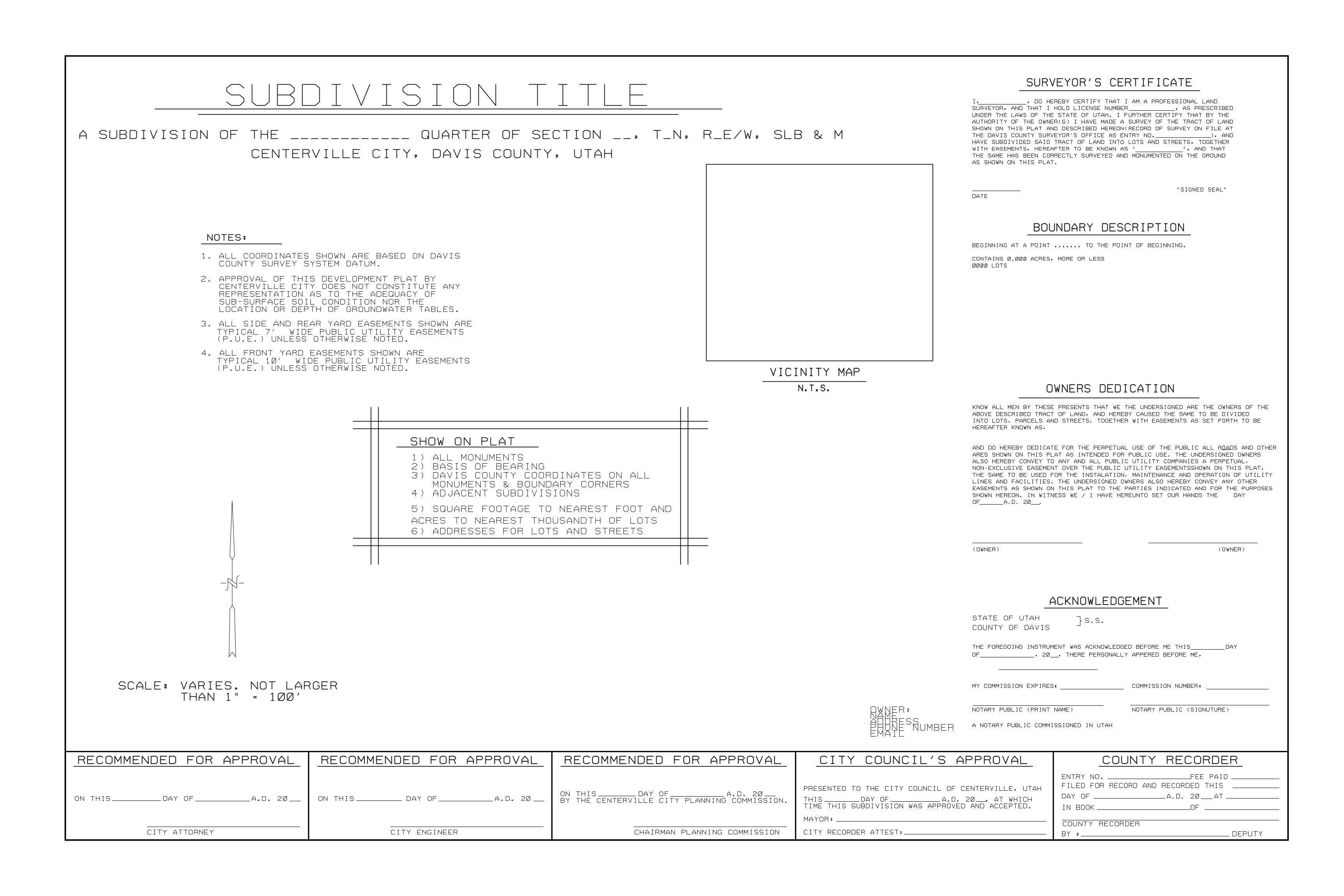
COUNTY RECORDER
CITY ATTORNEY
FILED FOR RECORD AND RECORDED THIS
IN BOOK OF
COUNTY RECORDER
BY : DEPUTYCITY ENGINEER
RECOMMENDED FOR APPROVAL
CHAIRMAN PLANNING COMMISSION
CITY COUNCIL'S APPROVAL
CITY RECORDER ATTEST:
MAYOR:
RECOMMENDED FOR APPROVALRECOMMENDED FOR APPROVAL
PRESENTED TO THE CITY COUNCIL OF CENTERVILLE, UTAH
ENTRY NO. FEE PAID
TIME THIS SUBDIVISION WAS APPROVED AND ACCEPTED.BY THE CENTERVILLE CITY PLANNING COMMISSION.ON THIS DAY OF A.D. 20 ON THIS DAY OF A.D. 20ON THIS DAY OF A.D. 20
THIS DAY OF A.D. 20 , AT WHICHDAY OF A.D. 20 AT
BOUNDARY DESCRIPTION
SURVEYOR'S CERTIFICATE
STATE OF UTAH
COUNTY OF DAVIS
ACKNOWLEDGEMENT
]S.S.
OWNERS DEDICATION
NOTES:
SUBDIVISION TITLE
CENTERVILLE CITY, DAVIS COUNTY, UTAH
SHOW ON PLAT
TYPICAL 7' WIDE PUBLIC UTILITY EASEMENTS
CENTERVILLE CITY DOES NOT CONSTITUTE ANY
REPRESENTATION AS TO THE ADEQUACY OF
SUB-SURFACE SOIL CONDITION NOR THE
LOCATION OR DEPTH OF GROUNDWATER TABLES.
1) ALL MONUMENTS
2) BASIS OF BEARING
3) DAVIS COUNTY COORDINATES ON ALL
MONUMENTS & BOUNDARY CORNERS
4) ADJACENT SUBDIVISIONS
(P.U.E.) UNLESS OTHERWISE NOTED.
3. ALL SIDE AND REAR YARD EASEMENTS SHOWN ARE
(P.U.E.) UNLESS OTHERWISE NOTED.
4. ALL FRONT YARD EASEMENTS SHOWN ARE
TYPICAL 10' WIDE PUBLIC UTILITY EASEMENTS
COUNTY SURVEY SYSTEM DATUM.
1. ALL COORDINATES SHOWN ARE BASED ON DAVIS
2. APPROVAL OF THIS DEVELOPMENT PLAT BY
A SUBDIVISION OF THE ____________ QUARTER OF SECTION __, T_N, R_E/W, SLB & M
SCALE: VARIES. NOT LARGER
THAN 1" = 100'
0000 LOTS
CONTAINS 0.000 ACRES, MORE OR LESS
BEGINNING AT A POINT ....... TO THE POINT OF BEGINNING.
(OWNER) (OWNER)
OF A.D. 20 .
SHOWN HEREON. IN WITNESS WE / I HAVE HEREUNTO SET OUR HANDS THE DAY
EASEMENTS AS SHOWN ON THIS PLAT TO THE PARTIES INDICATED AND FOR THE PURPOSES
LINES AND FACILITIES. THE UNDERSIGNED OWNERS ALSO HEREBY CONVEY ANY OTHER
THE SAME TO BE USED FOR THE INSTALATION, MAINTENANCE AND OPERATION OF UTILITY
NON-EXCLUSIVE EASEMENT OVER THE PUBLIC UTILITY EASEMENTSSHOWN ON THIS PLAT,
ALSO HEREBY CONVEY TO ANY AND ALL PUBLIC UTILITY COMPANIES A PERPETUAL,
ARES SHOWN ON THIS PLAT AS INTENDED FOR PUBLIC USE. THE UNDERSIGNED OWNERS
AND DO HEREBY DEDICATE FOR THE PERPETUAL USE OF THE PUBLIC ALL ROADS AND OTHER
HEREAFTER KNOWN AS,
INTO LOTS, PARCELS AND STREETS, TOGETHER WITH EASEMENTS AS SET FORTH TO BE
ABOVE DESCRIBED TRACT OF LAND, AND HEREBY CAUSED THE SAME TO BE DIVIDED
KNOW ALL MEN BY THESE PRESENTS THAT WE THE UNDERSIGNED ARE THE OWNERS OF THE
A NOTARY PUBLIC COMMISSIONED IN UTAH
NOTARY PUBLIC (PRINT NAME) NOTARY PUBLIC (SIGNUTURE)
MY COMMISSION EXPIRES: COMMISSION NUMBER:
OF , 20 , THERE PERSONALLY APPERED BEFORE ME,
THE FOREGOING INSTRUMENT WAS ACKNOWLEDGED BEFORE ME THIS DAY
DATE
"SIGNED SEAL"
AS SHOWN ON THIS PLAT.
THE SAME HAS BEEN CORRECTLY SURVEYED AND MONUMENTED ON THE GROUND
WITH EASEMENTS, HEREAFTER TO BE KNOWN AS " ", AND THAT
HAVE SUBDIVIDED SAID TRACT OF LAND INTO LOTS AND STREETS, TOGETHER
THE DAVIS COUNTY SURVEYOR'S OFFICE AS ENTRY NO. ), AND
SHOWN ON THIS PLAT AND DESCRIBED HEREON(RECORD OF SURVEY ON FILE AT
AUTHORITY OF THE OWNER(S) I HAVE MADE A SURVEY OF THE TRACT OF LAND
UNDER THE LAWS OF THE STATE OF UTAH. I FURTHER CERTIFY THAT BY THE
SURVEYOR, AND THAT I HOLD LICENSE NUMBER , AS PRESCRIBED
I, , DO HEREBY CERTIFY THAT I AM A PROFESSIONAL LAND
EMAILPHONE NUMBERADDRESSNAMEOWNER:
VICINITY MAP
N.T.S.
ACRES TO NEAREST THOUSANDTH OF LOTS
5) SQUARE FOOTAGE TO NEAREST FOOT AND
6) ADDRESSES FOR LOTS AND STREETS