Embed Size (px)
Citation preview
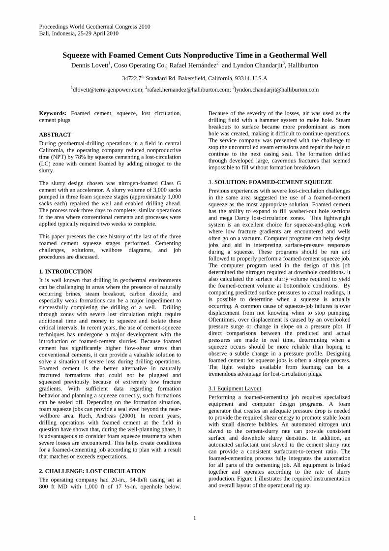
Proceedings World Geothermal Congress 2010 Bali, Indonesia, 25-29 April 2010
1
Squeeze with Foamed Cement Cuts Nonproductive Time in a Geothermal Well Dennis Lovett1, Coso Operating Co.; Rafael Hernández2 and Lyndon Chandarjit3, Halliburton
34722 7th Standard Rd. Bakersfield, California, 93314. U.S.A
[email protected]; [email protected]; [email protected]
Keywords: Foamed cement, squeeze, lost circulation, cement plugs
ABSTRACT
During geothermal-drilling operations in a field in central California, the operating company reduced nonproductive time (NPT) by 78% by squeeze cementing a lost-circulation (LC) zone with cement foamed by adding nitrogen to the slurry.
The slurry design chosen was nitrogen-foamed Class G cement with an accelerator. A slurry volume of 3,000 sacks pumped in three foam squeeze stages (approximately 1,000 sacks each) repaired the well and enabled drilling ahead. The process took three days to complete; similar operations in the area where conventional cements and processes were applied typically required two weeks to complete.
This paper presents the case history of the last of the three foamed cement squeeze stages performed. Cementing challenges, solutions, wellbore diagrams, and job procedures are discussed.
1. INTRODUCTION
It is well known that drilling in geothermal environments can be challenging in areas where the presence of naturally occurring brines, steam breakout, carbon dioxide, and especially weak formations can be a major impediment to successfully completing the drilling of a well. Drilling through zones with severe lost circulation might require additional time and money to squeeze and isolate these critical intervals. In recent years, the use of cement-squeeze techniques has undergone a major development with the introduction of foamed-cement slurries. Because foamed cement has significantly higher flow-shear stress than conventional cements, it can provide a valuable solution to solve a situation of severe loss during drilling operations. Foamed cement is the better alternative in naturally fractured formations that could not be plugged and squeezed previously because of extremely low fracture gradients. With sufficient data regarding formation behavior and planning a squeeze correctly, such formations can be sealed off. Depending on the formation situation, foam squeeze jobs can provide a seal even beyond the near-wellbore area. Ruch, Andreas (2000). In recent years, drilling operations with foamed cement at the field in question have shown that, during the well-planning phase, it is advantageous to consider foam squeeze treatments when severe losses are encountered. This helps create conditions for a foamed-cementing job according to plan with a result that matches or exceeds expectations.
2. CHALLENGE: LOST CIRCULATION
The operating company had 20-in., 94-lb/ft casing set at 800 ft MD with 1,000 ft of 17 ½-in. openhole below.
Because of the severity of the losses, air was used as the drilling fluid with a hammer system to make hole. Steam breakouts to surface became more predominant as more hole was created, making it difficult to continue operations. The service company was presented with the challenge to stop the uncontrolled steam emissions and repair the hole to continue to the next casing seat. The formation drilled through developed large, cavernous fractures that seemed impossible to fill without formation breakdown.
3. SOLUTION: FOAMED-CEMENT SQUEEZE
Previous experiences with severe lost-circulation challenges in the same area suggested the use of a foamed-cement squeeze as the most appropriate solution. Foamed cement has the ability to expand to fill washed-out hole sections and mega Darcy lost-circulation zones. This lightweight system is an excellent choice for squeeze-and-plug work where low fracture gradients are encountered and wells often go on a vacuum. Computer programs can help design jobs and aid in interpreting surface-pressure responses during a squeeze. These programs should be run and followed to properly perform a foamed-cement squeeze job. The computer program used in the design of this job determined the nitrogen required at downhole conditions. It also calculated the surface slurry volume required to yield the foamed-cement volume at bottomhole conditions. By comparing predicted surface pressures to actual readings, it is possible to determine when a squeeze is actually occurring. A common cause of squeeze-job failures is over displacement from not knowing when to stop pumping. Oftentimes, over displacement is caused by an overlooked pressure surge or change in slope on a pressure plot. If direct comparisons between the predicted and actual pressures are made in real time, determining when a squeeze occurs should be more reliable than hoping to observe a subtle change in a pressure profile. Designing foamed cement for squeeze jobs is often a simple process. The light weights available from foaming can be a tremendous advantage for lost-circulation plugs.
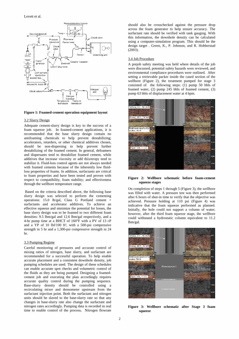
3.1 Equipment Layout
Performing a foamed-cementing job requires specialized equipment and computer design programs. A foam generator that creates an adequate pressure drop is needed to provide the required shear energy to promote stable foam with small discrete bubbles. An automated nitrogen unit slaved to the cement-slurry rate can provide consistent surface and downhole slurry densities. In addition, an automated surfactant unit slaved to the cement slurry rate can provide a consistent surfactant-to-cement ratio. The foamed-cementing process fully integrates the automation for all parts of the cementing job. All equipment is linked together and operates according to the rate of slurry production. Figure 1 illustrates the required instrumentation and overall layout of the operational rig up.
Lovett et al.
2
Figure 1: Foamed-cement operation equipment layout
3.2 Slurry Design
Adequate cement-slurry design is key to the success of a foam squeeze job. In foamed-cement applications, it is recommended that the base slurry design contain no antifoaming chemicals to help prevent destabilizing; accelerators, retarders, or other chemical additives chosen, should be non-dispersing to help prevent further destabilizing of the foamed cement. In general, defoamers and dispersants tend to destabilize foamed cement, while additives that increase viscosity or add thixotropy tend to stabilize it. Fluid-loss control agents are not always needed with foamed cements because of the inherently low fluid-loss properties of foams. In addition, surfactants are critical to foam properties and have been tested and proven with respect to compatibility, foam stability; and effectiveness through the wellbore temperature range.
Based on the criteria described above, the following base slurry design was selected to perform the cementing operations: 15.0 lb/gal, Class G Portland cement + surfactants and accelerator additives. To achieve an effective squeeze and minimize the potential for losses, the base slurry design was to be foamed to two different foam densities: 9.5 lbm/gal and 12.6 lbm/gal respectively, and a 4-hr pump time at a BHCT of 160°F with a PV of 13 cP and a YP of 10 lbf/100 ft², with a 500-psi compressive strength in 5 hr and a 1,300-psi compressive strength in 24 hr.
3.3 Pumping Regime
Careful monitoring of pressures and accurate control of mixing ratios of nitrogen, base slurry, and surfactant are recommended for a successful operation. To help enable accurate placement and a consistent downhole density, job pumping schedules are used. The design of these schedules can enable accurate spot checks and volumetric control of the fluids as they are being pumped. Designing a foamed-cement job and executing the plan accordingly requires accurate quality control during the pumping sequence. Base-slurry density should be controlled using a recirculating mixer and densometer upstream from the surfactant injection point. Both the surfactant and nitrogen units should be slaved to the base-slurry rate so that any changes in base-slurry rate also change the surfactant and nitrogen rates accordingly. Pumping data is recorded in real time to enable control of the process. Nitrogen flowrate
should also be crosschecked against the pressure drop across the foam generator to help ensure accuracy. The surfactant rate should be verified with tank gauging. With this information, the downhole density can be calculated using a computer-simulation program. This should be the design target . Green, K., P. Johnson, and R. Hobberstad (2003).
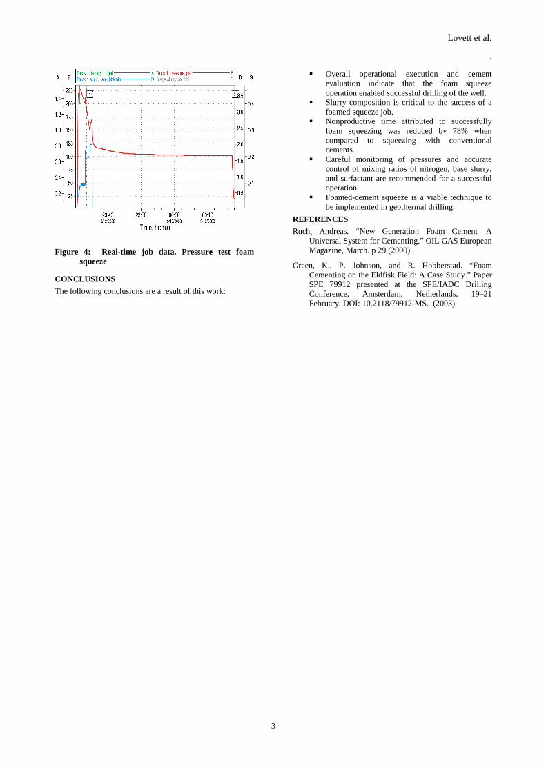
3.4 Job Procedure
A prejob safety meeting was held where details of the job were discussed, potential safety hazards were reviewed, and environmental compliance procedures were outlined. After setting a retrievable packer inside the cased section of the wellbore (Figure 2), the treatment pumped for stage 3 consisted of the following steps: (1) pump 50 bbls of foamed water, (2) pump 245 bbls of foamed cement, (3) pump 63 bbls of displacement water at 4 bpm.
Figure 2: Wellbore schematic before foam-cement squeeze stages
On completion of steps 1 through 5 (Figure 3), the wellbore was filled with water. A pressure test was then performed after 6 hours of shut-in time to verify that the objective was achieved. Pressure holding at 110 psi (Figure 4) was indicative that the foam squeeze performed as planned. Initially, the hole could not support a column of water; however, after the third foam squeeze stage, the wellbore could withstand a hydrostatic column equivalent to 11.2 lbm/gal.
Figure 3: Wellbore schematic after Stage 3 foam squeeze
Lovett et al.
.
3
Figure 4: Real-time job data. Pressure test foam squeeze
CONCLUSIONS
The following conclusions are a result of this work:
Overall operational execution and cement evaluation indicate that the foam squeeze operation enabled successful drilling of the well.
Slurry composition is critical to the success of a foamed squeeze job.
Nonproductive time attributed to successfully foam squeezing was reduced by 78% when compared to squeezing with conventional cements.
Careful monitoring of pressures and accurate control of mixing ratios of nitrogen, base slurry, and surfactant are recommended for a successful operation.
Foamed-cement squeeze is a viable technique to be implemented in geothermal drilling.
REFERENCES
Ruch, Andreas. “New Generation Foam Cement—A Universal System for Cementing.” OIL GAS European Magazine, March. p 29 (2000)
Green, K., P. Johnson, and R. Hobberstad. “Foam Cementing on the Eldfisk Field: A Case Study.” Paper SPE 79912 presented at the SPE/IADC Drilling Conference, Amsterdam, Netherlands, 19–21 February. DOI: 10.2118/79912-MS. (2003)