Embed Size (px)
Citation preview
49th International Conference on Environmental Systems ICES-2019-184 7-11 July 2019, Boston, Massachusetts
Copyright © 2019 SPEXone consortium (Airbus Defence and Space Netherlands BV and SRON Netherlands Institute
for Space Research)
SPEXone polarimeter instrument thermal design
Rob van Brakel1, Marc Oort2 and Jan Doornink3
Airbus Defence and Space Netherlands, Leiden, Netherlands
Jeroen Rietjens4 and Aaldert van Amerongen5
SRON Netherlands Institute for Space Research, Utrecht, Netherlands
SPEXone is a 6u narrow angle, compact spectropolarimeter used to measure the characteristics
of aerosols in the earth’s atmosphere. SPEXone is developed in a partnership between SRON
Netherlands Institute for Space Research and Airbus Defence and Space Netherlands with support
from the Netherlands Organization for Applied Scientific Research (TNO) as a Dutch contribution
to the NASA PACE observatory launching in 2022. SPEXone is a design to cost instrument which
implies there is a fixed budget which shall not be exceeded. The SPEXone polarimeter consists of
an aluminium housing with a radiant cooler and contains one detector module, a reflective
telescope, a transmissive PMO and a reflective grating spectrometer. This paper presents the
thermal design approach. The primary goal of the thermal design is to provide a stable thermal
environment needed for mechanical and optical stability and performance. There were several
design challenges. First, to create a stable thermal environment, temperature fluctuations and
gradients need to be reduced. The temperature level of the detector will be controlled at 293K with
an allowed narrow accuracy range of 0.15K (RMS). In addition, the instrument thermo mechanical
design should be insensitive for thermo elastic loads in order to ensure a stable optical alignment.
Special attention has been put into the control of thermomechanical effects by means of a
Structural, Thermal and Optical Performance (STOP) analysis. Important part of the verification
is to assess the spot size and spot position accuracy (allowed variation 11µm +/-5%). Second, the
implementation of the design-to-cost principle led to the use of a COTS detector module. Some of
the common design practices for narrow range active temperature controlled components could
not be established. Special attention has been put in the design and verification of the detector
temperature control. Analysis has shown that the design is fully compliant to all requirements. The
instrument is approaching the final integration and test phase including a dedicated thermal
balance test planned for the first half of 2020.
Nomenclature
1 Technical Specialist, Engineering Department, [email protected] 2 SPEXone Systems Engineer, Instruments and Services Department, [email protected] 3 Systems Engineer, Technology Department, [email protected] 4 Instrument Scientist, [email protected] 5 SPEXone project manager, [email protected]
ADSN = AIRBUS Defence & Space Netherland BV
ACT = Across Track
ALT = Along Track
ATC = Active Temperature Control
COTS = Commercial Off The Shelf
DEM = Detector Module
DTC = Design To Cost
FOV = Field of View
HARP = Hyper Angular Rainbow Polarimeter
ICU = Internal Computer Unit
I-gain = integration gain factor for heater control
MLI = Multi-Layer Isolation
OCI = Ocean Color Instrument
PACE = Plankton, Aerosol, Cloud and ocean Ecosystem
PFM = Proto Flight Model
P-gain = proportional gain factor for heater control
PMO = Polarization Module
PWM = Pulse Width Modulation
RC = Radiant Cooler
RMS = Root Mean Square
SC = Spacecraft
SPEX = Spectro-Polarimeter for Planetary Exploration
SPM = Spectrometer
TB = Thermal Balance
TBTV = Thermal Balance and Thermal Vacuum
TCS = Thermal Control System
2
International Conference on Environmental Systems
I. Introduction
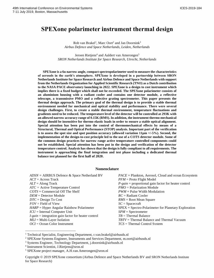
PEXone is a 6u6 five-angle spectropolarimeter instrument developed as a contributed payload for the NASA
Plankton, Aerosol, Cloud and ocean Ecosystem (PACE) observatory, to be launched in 2022. Making use of the
spectral modulation method to provide measurements of radiance and state of polarization in a continuous wavelength
spectrum and to achieve very high polarimetric accuracy, SPEXone will enable detailed characterization of aerosols
(e.g. absorption, composition, size, height). Figure 1 shows the scanning concept of SPEXone on board of the PACE
spacecraft [3].
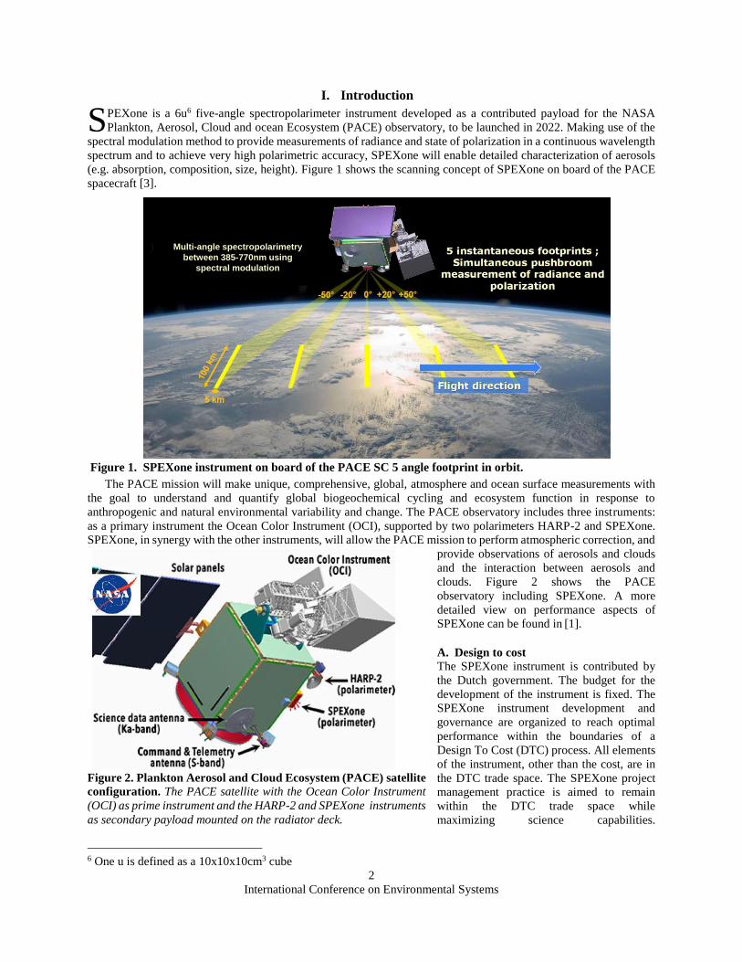
The PACE mission will make unique, comprehensive, global, atmosphere and ocean surface measurements with
the goal to understand and quantify global biogeochemical cycling and ecosystem function in response to
anthropogenic and natural environmental variability and change. The PACE observatory includes three instruments:
as a primary instrument the Ocean Color Instrument (OCI), supported by two polarimeters HARP-2 and SPEXone.
SPEXone, in synergy with the other instruments, will allow the PACE mission to perform atmospheric correction, and
provide observations of aerosols and clouds
and the interaction between aerosols and
clouds. Figure 2 shows the PACE
observatory including SPEXone. A more
detailed view on performance aspects of
SPEXone can be found in [1].
A. Design to cost
The SPEXone instrument is contributed by
the Dutch government. The budget for the
development of the instrument is fixed. The
SPEXone instrument development and
governance are organized to reach optimal
performance within the boundaries of a
Design To Cost (DTC) process. All elements
of the instrument, other than the cost, are in
the DTC trade space. The SPEXone project
management practice is aimed to remain
within the DTC trade space while
maximizing science capabilities.
6 One u is defined as a 10x10x10cm3 cube
S
Figure 1. SPEXone instrument on board of the PACE SC 5 angle footprint in orbit.
Dec 17 2018
SPEXOne Pre-CDR Engineering Peer Review
4
Multi-angle spectropolarimetry
between 385-770nm using
spectral modulation
Figure 2. Plankton Aerosol and Cloud Ecosystem (PACE) satellite
configuration. The PACE satellite with the Ocean Color Instrument
(OCI) as prime instrument and the HARP-2 and SPEXone instruments
as secondary payload mounted on the radiator deck.
3
International Conference on Environmental Systems
Implementation of the design to cost principle to achieve a high performance to cost ratio is visible in both the design
and AIT process. The detector module and the thermal flexible link are both commercial-of-the-shelf (COTS) items.
Also, to reduce cost of the calibration campaign, the majority of the calibration activities is performed under ambient
conditions.
B. Instrument configuration
The SPEXone instrument consists of a
single optical assembly and contains one
detector. It contains a telescope which looks
into 5 different along-track (ALT) directions
simultaneously. The telescope combines the
images from 5 ALT viewing directions onto
an input slit of the spectro-polarimeter. The
spectro-polarimeter consists of a polarization
modulation optics, which introduces a known
wavelength dependent polarization
modulation on the incoming light using a
chromatic modulator. A polarization beam
splitter in combination with linear wire grid
polarizers acts as an analyser and splits the
light into s & p-polarization states. A
spectrometer creates a spectrum of the
incoming light of two orthogonal
polarizations and images it on the detector.
The SPEXone instrument is built on
heritage with both technology and science.
The newly invented telescope (SRON patent)
specifications are based on mirror manufacturing technology of single point diamond turning on aluminium, as
available in the Netherlands. The polarization modulation optics module is based on an airborne proven unit as
developed in the SPEX airborne program. The spectrometer is a fully reflective design employing free-form
aluminium mirrors as proven in airborne test environment, in the Dutch Tropolite breadboard project (TNO/ADSN).
Manufacturability of the telescope was assessed in a breadboard. Pre-qualification of the polarization modulation unit
was done in a dedicated PMO breadboard work package.
Pre-development of some critical optical coatings in the design has been done in a dedicated coating breadboard
work package.
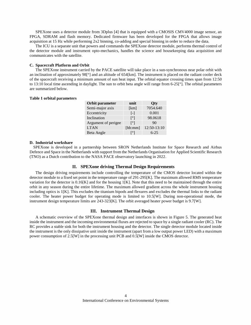
SPEXone uses spectral polarization
modulation to accurately measure the
state of linear polarization of the incident
light, as well as the absolute radiance
level in the spectral range from 385 to
770 nm. SPEXone has a swath of about
100 km and a spatial sampling distance
of 2.7 km along the swath in each of its
five viewing angles. SPEXone acquires
push-broom spectral images at a rate of 3
Hz, which corresponds to an along track
sampling distance of 2.3 km on-ground.
The optical quality at the slit and in the
spectrometer, in combination with
motion smear during the exposure time
of a single image, is tailored to achieve
Nyquist sampling of an image with a
spatial resolution of 4.6 x 5.4 km (ALT x
ACT).
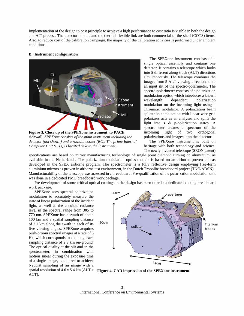
Figure 3. Close up of the SPEXone instrument to PACE
sidewall. SPEXone consists of the main instrument including the
detector (not shown) and a radiant cooler (RC). The prime Internal
Computer Unit (ICU) is located next to the instrument.
radiator MLI
SPEXone instrument
ICU
MLI
Figure 4. CAD impression of the SPEXone instrument.
radiator
apertures
Titanium bipods
20cm
13cm
4
International Conference on Environmental Systems
SPEXone uses a detector module from 3Dplus [4] that is equipped with a CMOSIS CMV4000 image sensor, an
FPGA, SDRAM and flash memory. Dedicated firmware has been developed for the FPGA that allows image
acquisition at 15 Hz while performing 2x2 binning, co-adding and special binning in order to reduce the data.
The ICU is a separate unit that powers and commands the SPEXone detector module, performs thermal control of
the detector module and instrument opto-mechanics, handles the science and housekeeping data acquisition and
communicates with the satellite.
C. Spacecraft Platform and Orbit
The SPEXone instrument carried by the PACE satellite will take place in a sun-synchronous near polar orbit with
an inclination of approximately 98[°] and an altitude of 654[km]. The instrument is placed on the radiant cooler deck
of the spacecraft receiving a minimum amount of sun heat input. The orbital equator crossing times span from 12:50
to 13:10 local time ascending in daylight. The sun to orbit beta angle will range from 6-25[°]. The orbital parameters
are summarized below.
Table 1 orbital parameters
Orbit parameter unit Qty
Semi-major axis [km] 7054.640
Eccentricity [-] 0.001
Inclination [°] 98.0618
Argument of perigee [°] 90
LTAN [hh:mm] 12:50-13:10
Beta Angle [°] 6-25
D. Industrial workshare
SPEXone is developed in a partnership between SRON Netherlands Institute for Space Research and Airbus
Defence and Space in the Netherlands with support from the Netherlands Organisation for Applied Scientific Research
(TNO) as a Dutch contribution to the NASA PACE observatory launching in 2022.
II. SPEXone driving Thermal Design Requirements
The design driving requirements include controlling the temperature of the CMOS detector located within the
detector module to a fixed set point in the temperature range of 291-295[K]. The maximum allowed RMS temperature
variation for the detector is 0.16[K] and for the housing 1[K]. Note that this need to be maintained through the entire
orbit in any season during the entire lifetime. The maximum allowed gradient across the whole instrument housing
including optics is 1[K]. This excludes the titanium bipods and flexures and excludes the thermal links to the radiant
cooler. The heater power budget for operating mode is limited to 10.5[W]. During non-operational mode, the
instrument design temperature limits are 243-323[K]. The orbit averaged heater power budget is 9.7[W].
III. Instrument Thermal Design
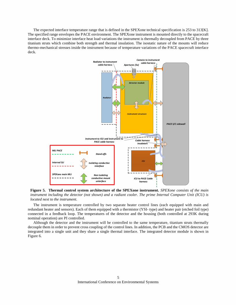
A schematic overview of the SPEXone thermal design and interfaces is shown in Figure 5. The generated heat
inside the instrument and the incoming environmental fluxes are rejected to space by a single radiant cooler (RC). The
RC provides a stable sink for both the instrument housing and the detector. The single detector module located inside
the instrument is the only dissipative unit inside the instrument (apart from a low output power LED) with a maximum
power consumption of 2.5[W] in the processing unit PCB and 0.5[W] inside the CMOS detector.
5
International Conference on Environmental Systems
The expected interface temperature range that is defined in the SPEXone technical specification is 253 to 313[K].
The specified range envelopes the PACE environment. The SPEXone instrument is mounted directly to the spacecraft
interface deck. To minimize interface heat load variations the instrument is thermally decoupled from PACE by three
titanium struts which combine both strength and thermal insulation. The isostatic nature of the mounts will reduce
thermo-mechanical stresses inside the instrument because of temperature variations of the PACE spacecraft interface
deck.
The instrument is temperature controlled by two separate heater control lines (each equipped with main and
redundant heater and sensors). Each of them equipped with a thermistor (YSI- type) and heater pair (etched foil type)
connected in a feedback loop. The temperatures of the detector and the housing (both controlled at 293K during
nominal operation) are PI controlled.
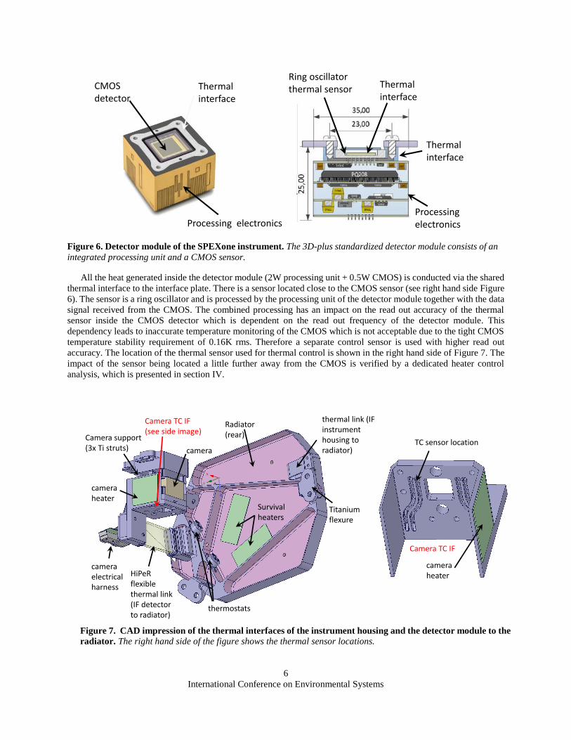
Although the detector and the instrument will be controlled to the same temperature, titanium struts thermally
decouple them in order to prevent cross coupling of the control lines. In addition, the PCB and the CMOS detector are
integrated into a single unit and they share a single thermal interface. The integrated detector module is shown in
Figure 6.
Figure 5. Thermal control system architecture of the SPEXone instrument. SPEXone consists of the main
instrument including the detector (not shown) and a radiant cooler. The prime Internal Computer Unit (ICU) is
located next to the instrument.
Instrument structure
Radiator
Detector module
ICU
Apertures (5x)
PACE S/C sidewall
ICU to PACE Cable harness
Radiator to instrument cable harness
Cable harness insulators
Instrument to ICU and instrument to PACE cable harness
Non isolating conductive mount
unterface
Isolating conductive interface
MLI PACE
Internal SLI
SPEXone main MLI
Camera to instrument cable harness
Stand offs
6
International Conference on Environmental Systems
All the heat generated inside the detector module (2W processing unit + 0.5W CMOS) is conducted via the shared
thermal interface to the interface plate. There is a sensor located close to the CMOS sensor (see right hand side Figure
6). The sensor is a ring oscillator and is processed by the processing unit of the detector module together with the data
signal received from the CMOS. The combined processing has an impact on the read out accuracy of the thermal
sensor inside the CMOS detector which is dependent on the read out frequency of the detector module. This
dependency leads to inaccurate temperature monitoring of the CMOS which is not acceptable due to the tight CMOS
temperature stability requirement of 0.16K rms. Therefore a separate control sensor is used with higher read out
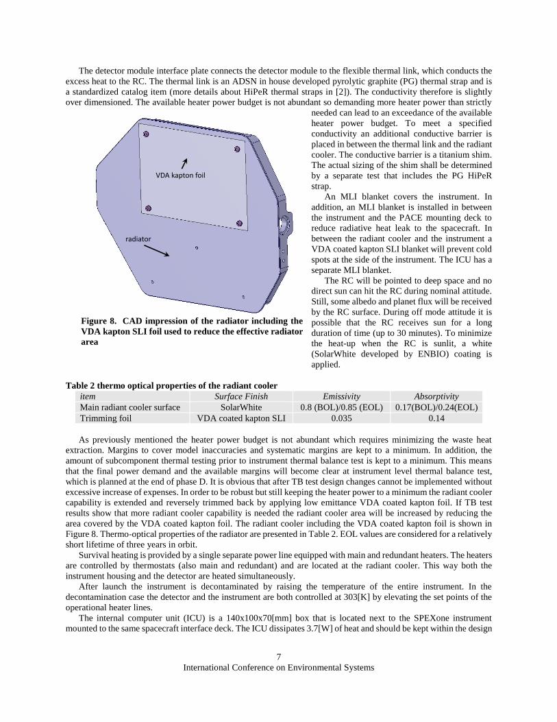
accuracy. The location of the thermal sensor used for thermal control is shown in the right hand side of Figure 7. The
impact of the sensor being located a little further away from the CMOS is verified by a dedicated heater control
analysis, which is presented in section IV.
Figure 6. Detector module of the SPEXone instrument. The 3D-plus standardized detector module consists of an
integrated processing unit and a CMOS sensor.
Thermal interface
CMOS detector
Processing electronics
Thermal interface
Thermal interface
Processing electronics
Ring oscillator thermal sensor
Figure 7. CAD impression of the thermal interfaces of the instrument housing and the detector module to the
radiator. The right hand side of the figure shows the thermal sensor locations.
camera
Titanium flexure
thermal link (IF instrument housing to radiator)
HiPeRflexible thermal link (IF detector to radiator)
Survival heaters
camera heater
thermostats
camera electrical harness
Radiator (rear)
Camera TC IF(see side image)
Camera TC IF
camera heater
TC sensor locationCamera support(3x Ti struts)
7
International Conference on Environmental Systems
The detector module interface plate connects the detector module to the flexible thermal link, which conducts the
excess heat to the RC. The thermal link is an ADSN in house developed pyrolytic graphite (PG) thermal strap and is
a standardized catalog item (more details about HiPeR thermal straps in [2]). The conductivity therefore is slightly
over dimensioned. The available heater power budget is not abundant so demanding more heater power than strictly
needed can lead to an exceedance of the available
heater power budget. To meet a specified
conductivity an additional conductive barrier is
placed in between the thermal link and the radiant
cooler. The conductive barrier is a titanium shim.
The actual sizing of the shim shall be determined
by a separate test that includes the PG HiPeR
strap.
An MLI blanket covers the instrument. In
addition, an MLI blanket is installed in between
the instrument and the PACE mounting deck to
reduce radiative heat leak to the spacecraft. In
between the radiant cooler and the instrument a
VDA coated kapton SLI blanket will prevent cold
spots at the side of the instrument. The ICU has a
separate MLI blanket.
The RC will be pointed to deep space and no
direct sun can hit the RC during nominal attitude.
Still, some albedo and planet flux will be received
by the RC surface. During off mode attitude it is
possible that the RC receives sun for a long
duration of time (up to 30 minutes). To minimize
the heat-up when the RC is sunlit, a white
(SolarWhite developed by ENBIO) coating is
applied.
Table 2 thermo optical properties of the radiant cooler
item Surface Finish Emissivity Absorptivity
Main radiant cooler surface SolarWhite 0.8 (BOL)/0.85 (EOL) 0.17(BOL)/0.24(EOL)
Trimming foil VDA coated kapton SLI 0.035 0.14
As previously mentioned the heater power budget is not abundant which requires minimizing the waste heat
extraction. Margins to cover model inaccuracies and systematic margins are kept to a minimum. In addition, the
amount of subcomponent thermal testing prior to instrument thermal balance test is kept to a minimum. This means
that the final power demand and the available margins will become clear at instrument level thermal balance test,
which is planned at the end of phase D. It is obvious that after TB test design changes cannot be implemented without
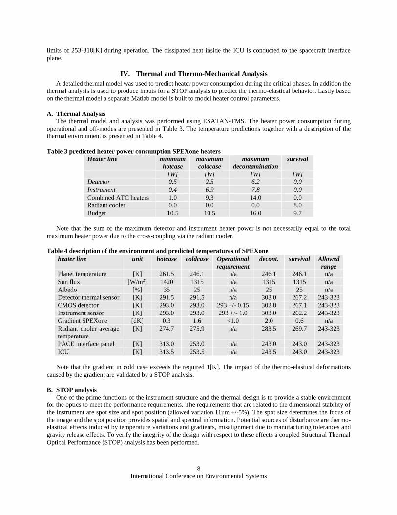
excessive increase of expenses. In order to be robust but still keeping the heater power to a minimum the radiant cooler
capability is extended and reversely trimmed back by applying low emittance VDA coated kapton foil. If TB test
results show that more radiant cooler capability is needed the radiant cooler area will be increased by reducing the
area covered by the VDA coated kapton foil. The radiant cooler including the VDA coated kapton foil is shown in
Figure 8. Thermo-optical properties of the radiator are presented in Table 2. EOL values are considered for a relatively
short lifetime of three years in orbit.
Survival heating is provided by a single separate power line equipped with main and redundant heaters. The heaters
are controlled by thermostats (also main and redundant) and are located at the radiant cooler. This way both the
instrument housing and the detector are heated simultaneously.
After launch the instrument is decontaminated by raising the temperature of the entire instrument. In the
decontamination case the detector and the instrument are both controlled at 303[K] by elevating the set points of the
operational heater lines.
The internal computer unit (ICU) is a 140x100x70[mm] box that is located next to the SPEXone instrument
mounted to the same spacecraft interface deck. The ICU dissipates 3.7[W] of heat and should be kept within the design
Figure 8. CAD impression of the radiator including the
VDA kapton SLI foil used to reduce the effective radiator
area
radiator
VDA kapton foil
8
International Conference on Environmental Systems
limits of 253-318[K] during operation. The dissipated heat inside the ICU is conducted to the spacecraft interface
plane.
IV. Thermal and Thermo-Mechanical Analysis
A detailed thermal model was used to predict heater power consumption during the critical phases. In addition the
thermal analysis is used to produce inputs for a STOP analysis to predict the thermo-elastical behavior. Lastly based
on the thermal model a separate Matlab model is built to model heater control parameters.
A. Thermal Analysis
The thermal model and analysis was performed using ESATAN-TMS. The heater power consumption during
operational and off-modes are presented in Table 3. The temperature predictions together with a description of the
thermal environment is presented in Table 4.
Table 3 predicted heater power consumption SPEXone heaters
Heater line minimum
hotcase
maximum
coldcase
maximum
decontamination
survival
[W] [W] [W] [W]
Detector 0.5 2.5 6.2 0.0
Instrument 0.4 6.9 7.8 0.0
Combined ATC heaters 1.0 9.3 14.0 0.0
Radiant cooler 0.0 0.0 0.0 8.0
Budget 10.5 10.5 16.0 9.7
Note that the sum of the maximum detector and instrument heater power is not necessarily equal to the total
maximum heater power due to the cross-coupling via the radiant cooler.
Table 4 description of the environment and predicted temperatures of SPEXone
heater line unit hotcase coldcase Operational
requirement
decont. survival Allowed
range
Planet temperature [K] 261.5 246.1 n/a 246.1 246.1 n/a
Sun flux [W/m2] 1420 1315 n/a 1315 1315 n/a
Albedo [%] 35 25 n/a 25 25 n/a
Detector thermal sensor [K] 291.5 291.5 n/a 303.0 267.2 243-323
CMOS detector [K] 293.0 293.0 293 +/- 0.15 302.8 267.1 243-323
Instrument sensor [K] 293.0 293.0 293 +/- 1.0 303.0 262.2 243-323
Gradient SPEXone [dK] 0.3 1.6 <1.0 2.0 0.6 n/a
Radiant cooler average
temperature
[K] 274.7 275.9 n/a 283.5 269.7 243-323
PACE interface panel [K] 313.0 253.0 n/a 243.0 243.0 243-323
ICU [K] 313.5 253.5 n/a 243.5 243.0 243-323
Note that the gradient in cold case exceeds the required 1[K]. The impact of the thermo-elastical deformations
caused by the gradient are validated by a STOP analysis.
B. STOP analysis
One of the prime functions of the instrument structure and the thermal design is to provide a stable environment
for the optics to meet the performance requirements. The requirements that are related to the dimensional stability of
the instrument are spot size and spot position (allowed variation 11µm +/-5%). The spot size determines the focus of
the image and the spot position provides spatial and spectral information. Potential sources of disturbance are thermo-
elastical effects induced by temperature variations and gradients, misalignment due to manufacturing tolerances and
gravity release effects. To verify the integrity of the design with respect to these effects a coupled Structural Thermal
Optical Performance (STOP) analysis has been performed.
9
International Conference on Environmental Systems
A FEM model has been built to analyze
the deformations caused by the effects
mentioned above. The goal of the analysis
is to find the displacements of all individual
optical elements. The deformations within
the mirrors itself are not considered. The
impact of not taking into account internal
deformation is expected to be relatively
small. All mirrors are monolithic
aluminium parts which are relatively small
compared to the housing. The dominant
effect is expected from deformations within
the aluminium housing. These rigid body
movements are calculated by the method
used by TNO on their STOP analysis used for the Sentinel 5 precursor instrument TROPOMI UVN spectrometer [5]
and the Sentinel 5 instrument UV1 spectrometer optics (UV1 SO) and the telescope beam splitter optical assembly
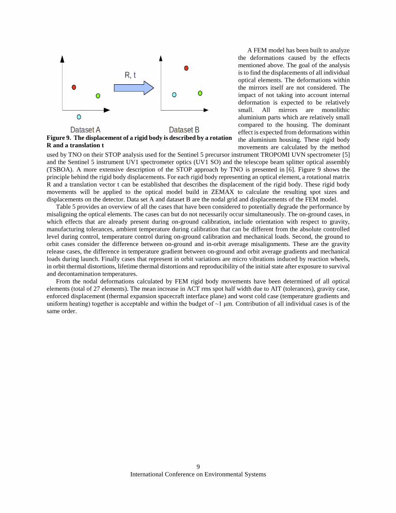
(TSBOA). A more extensive description of the STOP approach by TNO is presented in [6]. Figure 9 shows the
principle behind the rigid body displacements. For each rigid body representing an optical element, a rotational matrix
R and a translation vector t can be established that describes the displacement of the rigid body. These rigid body
movements will be applied to the optical model build in ZEMAX to calculate the resulting spot sizes and
displacements on the detector. Data set A and dataset B are the nodal grid and displacements of the FEM model.
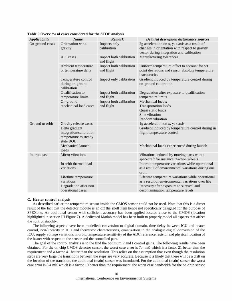
Table 5 provides an overview of all the cases that have been considered to potentially degrade the performance by
misaligning the optical elements. The cases can but do not necessarily occur simultaneously. The on-ground cases, in
which effects that are already present during on-ground calibration, include orientation with respect to gravity,
manufacturing tolerances, ambient temperature during calibration that can be different from the absolute controlled
level during control, temperature control during on-ground calibration and mechanical loads. Second, the ground to
orbit cases consider the difference between on-ground and in-orbit average misalignments. These are the gravity
release cases, the difference in temperature gradient between on-ground and orbit average gradients and mechanical
loads during launch. Finally cases that represent in orbit variations are micro vibrations induced by reaction wheels,
in orbit thermal distortions, lifetime thermal distortions and reproducibility of the initial state after exposure to survival
and decontamination temperatures.
From the nodal deformations calculated by FEM rigid body movements have been determined of all optical
elements (total of 27 elements). The mean increase in ACT rms spot half width due to AIT (tolerances), gravity case,
enforced displacement (thermal expansion spacecraft interface plane) and worst cold case (temperature gradients and
uniform heating) together is acceptable and within the budget of ~1 μm. Contribution of all individual cases is of the
same order.
Figure 9. The displacement of a rigid body is described by a rotation
R and a translation t
10
International Conference on Environmental Systems
Table 5 Overview of cases considered for the STOP analysis
C. Heater control analysis
As described earlier the temperature sensor inside the CMOS sensor could not be used. Note that this is a direct
result of the fact that the detector module is an off the shelf item hence not specifically designed for the purpose of
SPEXone. An additional sensor with sufficient accuracy has been applied located close to the CMOS (location
highlighted in section III Figure 7). A dedicated Matlab model has been built to properly model all aspects that affect
the control stability.
The following aspects have been modelled: conversion to digital domain, time delay between ICU and heater
control, non-linearity in ICU and thermistor characteristics, quantization in the analogue-digital-conversion of the
ICU, supply voltage variations in orbit, temperature sensitivity of the ADC reference resistor and physical location of
the heater with respect to the sensor and the controlled part.
The goal of the control analysis is to the find the optimum P and I control gains. The following results have been
obtained. For the on chip CMOS detector sensor, the worst case error is 7.4 mK which is a factor 21 better than the
requirement and a factor 41 better than the resolution. This relies on the assumption that even though the resolution
steps are very large the transitions between the steps are very accurate. Because it is likely that there will be a drift on
the location of the transition, the additional (main) sensor was introduced. For the additional (main) sensor the worst
case error is 8.4 mK which is a factor 19 better than the requirement. the worst case bandwidth for the on-chip sensor
Applicability Name Remark Detailed description disturbance sources
On-ground cases Orientation w.r.t.
gravity
Impacts only
calibration
2g acceleration on x, y, z axis as a result of
changes in orientation with respect to gravity
vector during integration and calibration
AIT cases Impact both calibration
and flight
Manufacturing tolerances.
Ambient temperature
or temperature delta
Impact both calibration
and flight
Uniform temperature offset to account for set
point deviations and sensor absolute temperature
inaccuracies
Temperature control
during on-ground
calibration
Impact only calibration Gradient induced by temperature control during
on-ground calibration
Qualification to
temperature limits
Impact both calibration
and flight
Degradation after exposure to qualification
temperature limits
On-ground
mechanical load cases
Impact both calibration
and flight
Mechanical loads:
Transportation loads
Quasi static loads
Sine vibration
Random vibration
Ground to orbit Gravity release cases 1g acceleration on x, y, z axis
Delta gradient
integration/calibration
temperature to steady
state BOL
Gradient induced by temperature control during in
flight temperature control
Mechanical launch
loads
Mechanical loads experienced during launch
In orbit case Micro vibrations Vibrations induced by moving parts within
spacecraft for instance reaction wheels
In orbit thermal load
variations
In orbit temperature variations while operational
as a result of environmental variations during one
orbit
Lifetime temperature
variations
Lifetime temperature variations while operational
as a result of environmental variations over life
Degradation after non-
operational cases
Recovery after exposure to survival and
decontamination temperature levels
11
International Conference on Environmental Systems
is 1.2 mHz and for the additional (main) sensor 3.4 mHz. This is because the additional (main) sensor is closer to the
heaters than the main sensor.
For the housing heater the worst case error is 9.1 mK which is a factor 109 better than the requirement. For the
redundant heater the worst case error is 0.7 mK which is a factor 1490 better than the requirement and a factor 15
better than the resolution. The worst case bandwidth for the main heater is 0.7 mHz and for the redundant heater 3.7
mHz. This is because the redundant heater is closer to the sensor.
V. Conclusion
The thermal design of the SPEXone instrument is presented. The thermal modelling results indicates that the
thermal control system of the SPEXone module will be able to obtain operational temperatures within limits and
provide stability for optimal performance. Additional STOP analysis confirms that the deformations of the optical
elements remain within limits.
VI. Acknowledgements
The authors would like to acknowledge the Netherlands Space Office (NSO) and the Ministry of Education Culture
and Science (OCW), the Dutch organization of Scientific Research (NWO), the Netherlands Institute for Space
Research (SRON) and Airbus Defence and Space Netherlands for funding the SPEXone project. We thank the NASA
PACE team for advice and guidance. In addition, we would like to thank 3Dplus for their cooperation in the SPEXone
project.
References
[1] Hasekamp, O.P. et al, “Aerosol measurements by SPEXone on the NASA PACE mission: expected retrieval capabilities”,
Journal of Quantitative Spectroscopy & Radiative Transfer, 2019, pp. 170-184
[2] Maas, A., “Development of Pyrolytic Graphite Applications in Spacecraft Thermal Control Systems”, proceedings 47th
international Conference on Environmental Systems, 16-20 July 2017, Charleston, SC
[3] van Amerongen A , Rietjens J.H.H. , Campo J , Dogan E , Dingjan J , Nalla R , et al. “Spexone: a compact multi-angle
spectro-polarimeter.” Proceedings International Conference on Space Optics 2018 .
[4] Virmontois et al. "Dose and Single-Event Effects on a Color CMOS Camera for Space Exploration" IEEE
TRANSACTIONS ON NUCLEAR SCIENCE, VOL. 66, NO. 1, JANUARY 2019
[5] te Voert M, Witvoet G and van Brakel R, "Thermo-Mechanical stability of TROPOMI", MIKRONIEK Professional Journal
on Precision Engineering, p 5-10 issue 3 2014
[6] Verlaan, A. et al, ”ITER Upper Port Wide Angle Viewing System Optical Design and Performance Analysis”, Fusion
Engineering and Design, Vol. 136 Part B, November 2018 p936-944


![PACE Ocean Color Instrument & Polarimeters _… · HARP2 OCI SPEXone HARP2 Spectral range [bandwith] 342.5 - 887.5 @ 5 nm steps [5 nm] 385 - 770 nm @ 2-4 nm steps 440, 550, 670 [10](https://img.pdfslide.us/doc/110x75/5f9c5e205a903c6cbc47e316/pace-ocean-color-instrument-polarimeters-harp2-oci-spexone-harp2-spectral.jpg)