Embed Size (px)
Citation preview
Project Documentation Document SPEC-0055
Revision D
Visible Spectro-Polarimeter (ViSP) Instrument Science Requirement
D. Elmore
1, H. Socas-Navarro, R. Casini
3 June 2014
Name Date
Released By: Joseph McMullin
Project Manager 30-January-2015
1 Responsible author
ViSP ISRD
SPEC-0055, Rev D Page ii
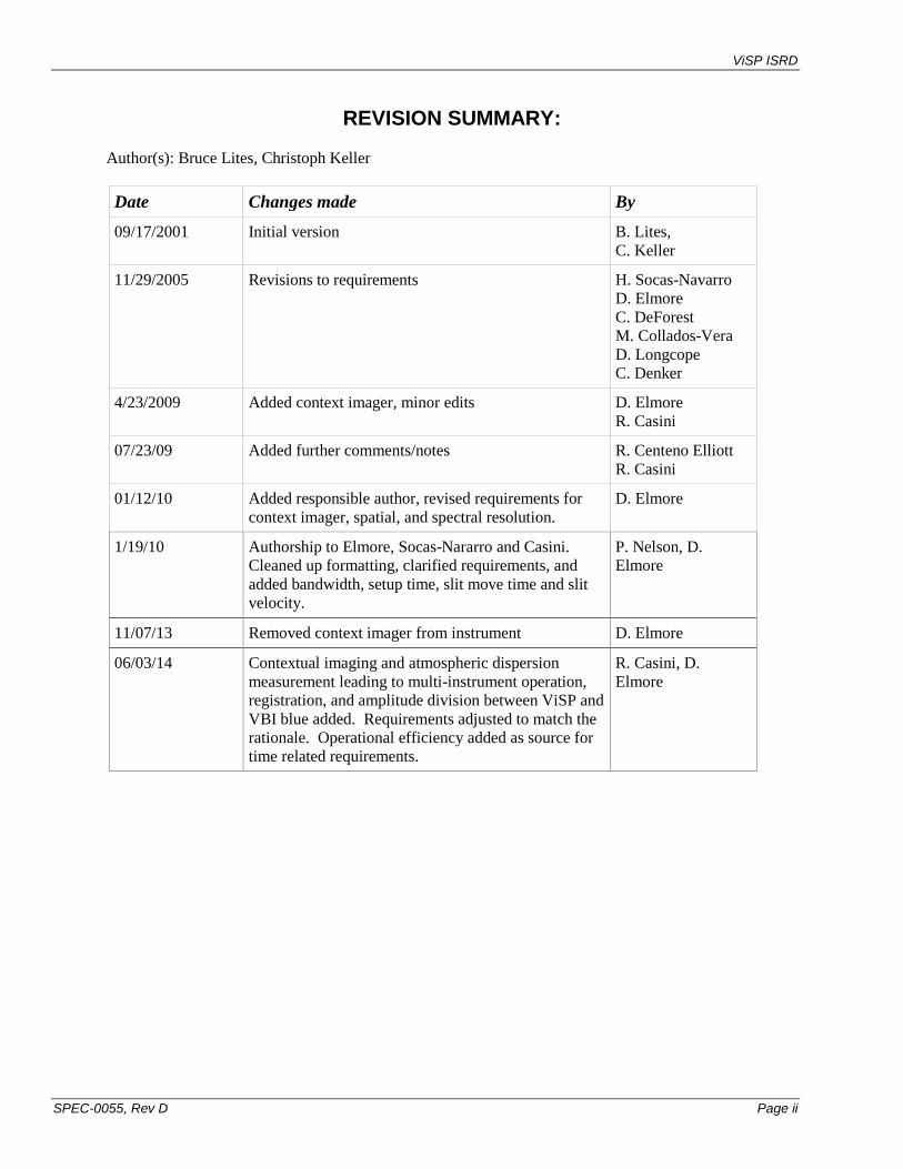
REVISION SUMMARY:
Author(s): Bruce Lites, Christoph Keller
Date Changes made By
09/17/2001 Initial version B. Lites,
C. Keller
11/29/2005 Revisions to requirements H. Socas-Navarro
D. Elmore
C. DeForest
M. Collados-Vera
D. Longcope
C. Denker
4/23/2009 Added context imager, minor edits D. Elmore
R. Casini
07/23/09 Added further comments/notes R. Centeno Elliott
R. Casini
01/12/10 Added responsible author, revised requirements for
context imager, spatial, and spectral resolution.
D. Elmore
1/19/10 Authorship to Elmore, Socas-Nararro and Casini.
Cleaned up formatting, clarified requirements, and
added bandwidth, setup time, slit move time and slit
velocity.
P. Nelson, D.
Elmore
11/07/13 Removed context imager from instrument D. Elmore
06/03/14 Contextual imaging and atmospheric dispersion
measurement leading to multi-instrument operation,
registration, and amplitude division between ViSP and
VBI blue added. Requirements adjusted to match the
rationale. Operational efficiency added as source for
time related requirements.
R. Casini, D.
Elmore
ViSP ISRD
SPEC-0055, Rev D Page iii
Table of Contents
1. INTRODUCTION ................................................................................................... 1
1.1 PURPOSE ............................................................................................................... 1 1.2 SCOPE ................................................................................................................... 1 1.3 TRACKING .............................................................................................................. 1 1.4 APPLICABLE DOCUMENTS ......................................................................................... 1 1.5 ABBREVIATIONS AND ACRONYMS .............................................................................. 1
2. MISSION ............................................................................................................... 2 3. SCIENCE ANALYSIS ............................................................................................ 3 3.1 ZEEMAN DIAGNOSTICS OF SOLAR MAGNETIC FIELDS ................................................. 3 3.2 HANLE EFFECT DIAGNOSTICS .................................................................................. 3 3.3 IMPACT POLARIZATION DIAGNOSTICS ........................................................................ 3
3.4 NEW DIAGNOSTICS ................................................................................................. 4
4. CHARACTERISTICS............................................................................................. 5 4.1 WAVELENGTH RANGE 380 – 900 NM ........................................................................ 5
4.2 RAPID MODULATION/DEMODULATION OF POLARIZATION ............................................. 5 4.3 WAVELENGTH DIVERSITY ......................................................................................... 5 4.4 ADAPTIVE OPTICS ................................................................................................... 5
4.5 MULTI-INSTRUMENT OPERATION .............................................................................. 5 4.6 INSTRUMENT CONCEPT ........................................................................................... 6
5. REQUIREMENTS ................................................................................................. 7 5.1 WAVELENGTH RANGE: 380 NM – 900 NM .................................................................. 7 5.2 SIMULTANEOUS WAVELENGTH COVERAGE: 3 LINES .................................................... 7
5.3 SPATIAL RESOLUTION: 2X TELESCOPE RESOLUTION................................................... 7 5.4 IMAGE QUALITY ....................................................................................................... 7
5.5 SPATIAL FIELD OF VIEW ............................................................................................ 7 5.6 SPECTROGRAPH RESOLVING POWER ........................................................................ 7
5.7 SLIT SCAN REPEATABILITY ....................................................................................... 8 5.8 SLIT SCAN ACCURACY ............................................................................................. 8
5.9 POLARIMETRIC SENSITIVITY ...................................................................................... 8 5.10 POLARIMETRIC ACCURACY ....................................................................................... 8
5.11 TEMPORAL RESOLUTION .......................................................................................... 8 5.12 MULTI-INSTRUMENT OPERATION .............................................................................. 8 5.13 MULTI-INSTRUMENT REGISTRATION .......................................................................... 9 5.14 COMBINED OPERATION WITH VISIBLE BROADBAND IMAGER ......................................... 9 5.15 SPECTRAL BANDWIDTH ............................................................................................ 9
5.16 SETUP TIME ............................................................................................................ 9
5.17 SLIT MOVE TIME ...................................................................................................... 9
5.18 SLIT SLEW VELOCITY ............................................................................................... 9
ViSP ISRD
SPEC-0055, Rev C Page 1 of 9
1. INTRODUCTION
1.1 PURPOSE
This document defines the requirements for the visible spectro-polarimeter (ViSP). It is one of the initial
focal-plane instruments for the DKIST.
1.2 SCOPE
This document covers science requirements of the visible spectro-polarimeter. Designers of the optical,
mechanical, electronic, and software systems to develop the various subsystems should use this
document.
1.3 TRACKING
It is the role of the responsible author to work with the instrument scientist and other co-authors on
development of the ISRD. The responsible author tracks changes and maintains revisions within the
DKIST documentation system.
1.4 APPLICABLE DOCUMENTS
[1] ATST Proposal
[2] DKIST Science Requirements Document, SPEC-0001
1.5 ABBREVIATIONS AND ACRONYMS
ATST Advanced Technology Solar Telescope
ViSP Visible Spectro-Polarimeter
DKIST Daniel K Inouye Solar Telescope
DL-NIRSP Diffraction Limited Near Infra-Red Spectro-Polarimeter
SRD Science Requirements Document
Ic Average quiet Sun continuum intensity
MTF Modulation Transfer Function
VTF Visible Tunable Filter
VBI Visible Broadband Imager
GOS Gregorian Optical System
ViSP ISRD
SPEC-0055, Rev C Page 2 of 9
2. MISSION The ATST visible spectro-polarimeter (ViSP) is an instrument expected to provide precision
measurements of the full state of polarization (i.e., all four Stokes parameters I, Q, U, and V; that is,
intensity plus a full description of both linear and circular polarization) simultaneously at diverse
wavelengths in the visible spectrum, and fully resolving (or nearly so) the spectral profiles of spectrum
lines originating in the solar atmosphere. Such measurements provide quantitative diagnostics of the
magnetic field vector as a function of height in the solar atmosphere, along with the associated variation
of the thermodynamic properties. Furthermore, information about protons and electrons in flares can be
deduced from analyzing the polarization of strong lines during flares.
Polarization measurements always involve the detection of intensity differences, i.e. at least two
measurements are needed to determine a polarization signal. Reliable polarimetry requires that the two
intensities be detected within a period that is short with respect to the fastest changes of seeing. This can
be achieved either by spatial modulation, which guarantees absolutely simultaneous measurements, or
temporal modulation. Spatial modulation has the drawback that the two (or more) beams do not pass the
optics along the same optical path. Differential aberrations may then become crucial. Furthermore,
spatial modulation requires that different detectors or detector areas detect the various beams, which
makes the measurements susceptible to differential gain effects. Temporal modulation should be
performed at frequencies well above the fastest changes due to seeing.
ViSP ISRD
SPEC-0055, Rev C Page 3 of 9
3. SCIENCE ANALYSIS
3.1 ZEEMAN DIAGNOSTICS OF SOLAR MAGNETIC FIELDS
The Zeeman effect produces splitting of atomic states in the presence of a magnetic field, and the
separated states respond differently to the absorption of polarization (or, alternatively, emit light of
specific states of polarization.) The Zeeman effect forms the basis for most of the polarization
diagnostics of solar magnetic fields. Structure in the magnetic field exists on many size scales, and the
structure at the smallest scales is extremely important to the heating and energy balance of the solar
atmosphere. Quantitative measurements of the magnetic field vector at very small scales thus play a
crucial role in understanding the fundamental nature of the atmosphere of the Sun and other stars. A
primary objective of the ATST ViSP is to carry out the needed polarization measurements in multiple
spectral lines simultaneously. When pairs of lines differing in their sensitivity to the Zeeman effect, but
otherwise having similar formation properties, are measured simultaneously, one has enhanced sensitivity
to measurement of the magnetic field and insight into the magnetic fill factor. Line pairs, such as the FeI
pair at 630 nm or the FeI lines at [524.7, 525.0 nm], are prominent examples. Combining such
measurements for lines forming from the photosphere to the chromosphere, all measured simultaneously,
will form the basis for a comprehensive diagnostic of the vector magnetic field as a function of height in
the solar atmosphere. The choices for combinations of lines should not be restricted from the outset.
Such flexibility is the hallmark and the unique advantage of a ground-based instrument of this type.
Furthermore, the scientific value of ViSP measurements will be greatly magnified if it is able to operate
simultaneously with the near infrared polarimeter (NIRSP). Co-spatial and co-temporal observations in
the visible and near infrared, at high angular resolution, will permit one to examine the distribution of
weak and strong fields that are believed to coexist in the solar photosphere. For this reason, it is required
that the ViSP and NIRSP be closely coupled in their development.
3.2 HANLE EFFECT DIAGNOSTICS
The line formation of some spectrum lines is dominated by scattering in the solar atmosphere and, due to
the anisotropic nature of the solar illumination, these lines will exhibit a linear polarization signal arising
from the scattering process. When a weak magnetic field is also present, generally less than 100 Gauss,
the linear polarization of these scattering lines is modified, through the Hanle effect, with respect to the
field-free case, opening the possibility of a diagnostics of weak fields. In addition, atomic level crossings
induced by these weak fields in complex atoms, produce even more exotic polarization effects, like the
alignment-to-orientation (A-O) mechanism responsible for the appearance of I-like signals in Stokes V,
which greatly enrich the diagnostic potential of scattering lines. In particular, the vector field structure
within prominences as determined from the Hanle effect and the A-O mechanism is a very important
science objective for ATST. Because of the subtleness of these effects, such analysis requires high
sensitivity to both linear and circular polarizations as measured simultaneously in several lines throughout
the visible and near infrared. As in the case of the Zeeman effect, it is highly desirable to retain flexibility
in choice of wavelength regions. Unlike most of the Zeeman effect analyses, Hanle diagnostics are often
carried out in prominences or the chromosphere above the solar limb, so that the instrumentation needs to
be able to operate at a much lower ambient flux level. If possible, the Adaptive Optics System should
include an operation mode for the tracking of structures near the limb (see goal in 4.10).
3.3 IMPACT POLARIZATION DIAGNOSTICS
Electron and proton beams accelerated during flares produce linear polarization in the H line (656 nm).
Measurements of the magnitude and orientation of linear polarization provides information about the
particle beams. The amount of linear polarization is typically no larger than 10%. Since flares evolve
rapidly, the measurements need to be obtained with high temporal resolution (fractions of a second).

ViSP ISRD
SPEC-0055, Rev C Page 4 of 9
3.4 NEW DIAGNOSTICS
ViSP as a wavelength-versatile spectro-polarimeter will allow the pursuit of new diagnostics, which will
certainly be developed as our understanding of the Sun system moves forward.
ViSP ISRD
SPEC-0055, Rev C Page 5 of 9
4. CHARACTERISTICS
4.1 WAVELENGTH RANGE 380 – 900 NM
The visible range should include the molecular bands and the Ca II H, K lines in the range 380-400 nm.
Since lines in the ultraviolet show larger scattering polarization than in the visible and near-infrared, it
would be interesting to observe down to the atmospheric cutoff at 296 nm. However, that should only
remain a goal. This sets the violet limit for the instrument at 380 nm. At longer wavelengths, it is
important to cover the Ca II infrared lines near 850 nm and other lines between 850 and 900 nm that have
been used for polarimetry. While it is feasible to build the ViSP with sensitivity out to the He I 1083 nm
line and beyond, the quantum efficiency of visible-light detectors at 1083 nm is at least an order of
magnitude smaller as compared with near-infrared detectors. For observations including NIR lines, ViSP
could be equipped with a NIR camera or observations could be performed simultaneously with the DL-
NIRSP.
4.2 RAPID MODULATION/DEMODULATION OF POLARIZATION
Seeing and rapid changes of solar origin produce crosstalk among the measured polarization states and
generates false polarization signals if the polarization modulation is carried out at low frequencies. It is
desirable to perform the polarization analysis rapidly, consistent with the expected signal levels. When
the polarization modulation is done at a frequency of 500 Hz or greater, this spurious source of
polarization is eliminated. There are other ways to mitigate this effect (such as done for the Advanced
Stokes Polarimeter) at lower modulation frequencies, but the technology for rapid
modulation/demodulation, at high efficiency, now appears to be at hand. The ATST ViSP should be
designed from the outset to take advantage of this development.
4.3 WAVELENGTH DIVERSITY
The ViSP should be capable of polarization measurements in at least 3 separate wavelength bands
simultaneously. The optical design of the spectrograph should allow for stigmatic imaging of the
spectrum at diverse wavelengths.
4.4 ADAPTIVE OPTICS
The ViSP will necessarily be operated in conjunction with adaptive optical correction of the wave front
from the telescope.
4.5 MULTI-INSTRUMENT OPERATION
It must be possible for the ViSP to operate simultaneously with the 2-D imaging science instruments of
the DKIST (VBI blue, VBI red, and VTF). The primary function is to provide contextual information of
the Sun’s evolution over the observed FOV while it is being scanned by the ViSP slit. When used with
alignment targets at the GOS these contextual images can be used to calibrate the ViSP slit location with
respect to the other DKIST instruments (VBI, VTF, and DL-NIRSP) and to the absolute system of
heliocentric coordinates.
The secondary function is to use this multi-instrument capability to sequentially image continuum
wavelengths combined with the ViSP spectro-heliogram over the span of the observation, so that the
atmospheric dispersion can be determined as a function of wavelength. The dispersion evolves with solar
elevation so this may be a continuous process. With a dispersion model one can predict the location of
the slit at one wavelength while positioning the slit with a different wavelength. For example, a
chromospheric wavelength (e.g., Ca II K and Hα) could be used to locate the slit with respect to a
filament even though the filament is not readily identified at the wavelengths the ViSP is configured to
observe.
To achieve required signal to noise each instrument requires all light within its wavelength range.
Normally light distribution among instruments will therefore by through spectral division. Since the
ViSP ISRD
SPEC-0055, Rev C Page 6 of 9
ViSP operates at twice the diffraction limit of DKIST, full signal to noise in order to create reconstructed
images is not required of the VBI to provide contextual and atmospheric dispersion images for ViSP. It is
therefore possible to divide light between the ViSP and VBI blue by amplitude with ViSP receiving most
of the light.
4.6 INSTRUMENT CONCEPT
To meet these characteristics, a possible concept for the ViSP is sketched in broad terms as follows. The
polarization modulator would be a rotating retarder located in the beam beyond the primary focus/heat
dump. This configuration performs the polarization modulation early in the optical system. The only
instrumental polarization would arise from the off axis primary and secondary mirrors, which are constant
and easily measured to high precision. Since the modulation/demodulation is fast enough to eliminate
seeing crosstalk, the small instrumental polarization becomes even less of a concern. The rest of the
polarimeter resides at some convenient point later in the optical system. A dichroic beam splitter divides
the beam between the NIRSP and the ViSP. The ViSP disperser would be a high-order echelle
spectrograph of an all-reflecting design, perhaps a Littrow-type, in order to maintain image quality over
the desired wavelength range. The detectors would be pixel arrays with high quantum efficiency.
ViSP ISRD
SPEC-0055, Rev C Page 7 of 9
5. REQUIREMENTS
5.1 WAVELENGTH RANGE: 380 NM – 900 NM
Requirement: The ViSP operates from 380 to 900 nm.
Goal: It is desirable to perform polarimetry from 380nm to 1600 nm.
Priority: 1
Source: SRD 2.11-2.13 (Ca K - Ca IRT)
5.2 SIMULTANEOUS WAVELENGTH COVERAGE: 3 LINES
Requirement: The ViSP images up to three spectral ranges simultaneously. It is understood that not all
line combinations may be capable of meeting the temporal, resolution, bandwidth, and/or resolving power
requirements.
Goal: Five lines simultaneously.
Priority: 1
Source: SRD 2.11-2.13 (multiple heights)
5.3 SPATIAL RESOLUTION: 2X TELESCOPE RESOLUTION
The ViSP should make use of the high spatial resolution capabilities offered by the telescope. However,
polarimetry right at the diffraction limit is rarely very productive because of the strongly reduced MTF of
the telescope and the very limited signal-to-noise ratio. Experience from existing telescopes shows that
useful polarimetry is performed down to about twice the diffraction-limited resolution element. Meeting
the spatial resolution requirement at all observed wavelengths is possible by choosing the proper slit
width for the shortest wavelength, but not all other requirements (such as temporal resolution; see 5.11)
may be satisfied.
Requirement: Twice the size of the telescope diffraction limit at all wavelengths. The slit width is less
than or equal to /D with a D of 4 meters. The slit image is relayed to the camera and the pixel pitch is
sufficiently fine to maintain /D resolution along the slit.
Goal: It is desirable to be able to reach the diffraction limit.
Priority: 1
Source: SRD 3.1.2, 3.1.4, 3.1.7, 3.1.8, 3.2.2, 3.2.4
5.4 IMAGE QUALITY
Requirement: AO for disk observations
Goal: AO for disk and near limb observations (spicules, prominences)
Priority: 1
Source: SRD 3.1.3 (also most of 3.1 & 3.2)
5.5 SPATIAL FIELD OF VIEW
Requirement: The field of view should be square and at least 2 arcmin in both the slit and scan directions
to allow maps of moderate-sized active regions.
Goal: It is desirable to have a circular field of view of at least 2.8 arcmin.
Priority: 1
Source: SRD 3.1.5, 3.1.7, 3.1.8, 3.2.4
5.6 SPECTROGRAPH RESOLVING POWER
The spectrograph resolving power is defined as the wavelength of light divided by Δλ, where Δλ is the
smallest difference in wavelength between two monochromatic waves, which can be separated by the
spectrograph. In ViSP, Δλ is twice the FWHM of the image of the slit on the focal plane of the camera in
units of wavelength.
ViSP ISRD
SPEC-0055, Rev C Page 8 of 9
Requirement: 180,000 resolving power (3.5 pm at 630 nm)
Goal: 2.0pm to match the Doppler width in sunspot umbrae
Priority: 1
Source: SRD 3.1.5, 3.1.6, 3.1.7
5.7 SLIT SCAN REPEATABILITY
Requirement: +/- 1/2 a slit width for a slit which meets the spatial resolution requirements.
Goal: 1/10th of a slit width
Priority: 1
Source: Separability of spatial features (see req. 5.3)
5.8 SLIT SCAN ACCURACY
Over the field of view and following removal of periodic errors the position of the slit must be known to
an equivalent of 0.1 arcsec referenced to the Coudé room floor.
Requirement: 0.1 arcsec
Goal: 0.01 arcsec
Priority: 1
Source: Co-alignment with other instruments
5.9 POLARIMETRIC SENSITIVITY
Many science goals require both high polarimetric precision and high angular resolution. ATST will be
able to achieve S/N appropriate to this polarimetric precision with reasonably high angular resolution as a
consequence of its large aperture. It is recognized that spatial binning and long integration times may be
necessary to achieve the sensitivity requirement. Some science (notably 3.1.5, weak and turbulent fields)
requires at least 10-5
sensitivity.
Requirement: 10-4
Ic
Goal: 10-5
Ic
Priority: 1
Source: SRD 3.1.5, 3.3.1, 3.3.2
5.10 POLARIMETRIC ACCURACY
Requirement: After calibration polarimetric measurements can be determined with an accuracy of 5•10-4
Ic This places requirements upon the Camera and Polarimetry Analysis and Calibration Systems.
Goal: 10-4 Ic
Priority: 1
Source: Linearity of magnetic field measurements (SRD 3.1.x)
5.11 TEMPORAL RESOLUTION
Requirement: 10-3
Ic in 10 seconds at required spectral and spatial resolution, 500nm-900nm
Goal: less than 10-3
Ic in 10 seconds and/or over entire spectral range
Priority: 2
Source: SRD 3.1.2, 3.1.3, 3.2.2, 3.2.3
5.12 MULTI-INSTRUMENT OPERATION
Requirement: It shall be possible to configure the facility to spectrally divide the light between the ViSP
and any other instrument that shares Adaptive Optics.
Priority: 2
Source: Section 4.5
ViSP ISRD
SPEC-0055, Rev C Page 9 of 9
5.13 MULTI-INSTRUMENT REGISTRATION
Requirement: The facility shall provide a mechanism by which the ViSP can determine the alignment of
its field of view in translation, rotation, and scale factor with any other instrument that share Adaptive
Optics.
Priority: 2
Source: Section 4.5
5.14 COMBINED OPERATION WITH VISIBLE BROADBAND IMAGER
Requirement: Light can be divided by amplitude between the ViSP and the VBI blue channel with ViSP
receiving least 90% of the light.
Priority: 2
Source: Section 4.5
5.15 SPECTRAL BANDWIDTH
Requirement: Each focal plane image will have a minimum bandwidth of 1.1nm (at 630nm) in
configurations meeting the resolving power requirement. This is required to capture the core of wide
lines (e.g., CaII 8542) as well as neighboring continuum. The focal plane bandwidth scales with the
wavelength for a fixed resolving power. The spectral bandwidth can be increased using lower dispersion
gratings at lower resolving powers.
Goal: As wide as possible
Priority: 2
Source: SRD 2.11-2.13 (multiple heights)
5.16 SETUP TIME Requirement: The ViSP instrument must be capable of rapid reconfiguration to be able to capture short-
lived targets of opportunity (such as flares). This also facilitates the rapid re-scanning of solar regions
with more than one configuration to increase the number of lines surveyed and/or to optimize resolving
power in multiple lines. The spectrograph should be reconfigurable in at least one spectral channel in 10
minutes.
Goal: All image planes reconfigurable and/or a reconfiguration time of 1 minute
Priority: 2
Source: Operational Concepts Definition operational efficiency
5.17 SLIT MOVE TIME
Requirement: The maximum allowed time for a slit to move from one position to another position
immediately abutting it is 200ms (for a slit meeting the spatial resolution requirements).
Goal: 10ms
Priority: 2
Source: Operational Concepts Definition operational efficiency
5.18 SLIT SLEW VELOCITY
Requirement: The slit must slew over a 2 arcmin field of view in 30 seconds or less.
Goal: As fast as possible consistent with other positioning requirements
Priority: 2
Source: Operational Concepts Definition operational efficiency