Embed Size (px)
Citation preview

Specifications
Length. . . . . . . . . . . . . . . . . . . . . . . . 20 .7.in.(526mm)Height . . . . . . . . . . . . . . . . . . . . . . . . 7 .1.in.(180mm)Main.Rotor.Diameter. . . . . . . . . . . . . . 20 .3.in.(515mm)Tail.Rotor.Diameter. . . . . . . . . . . . . . . 5 .8.in.(148mm)Weight.RTF.with.Battery. . . . . . . . . . . . 10 .5.oz.(298.g)Main.Motor. . . . . . . . . . . . . . . . . . . . . 370.(installed)Tail.Motor. . . . . . . . . . . . . . . . . . . . . . N30.(installed)Battery. . . . . . . . . . . . . . . . . . . . . . . . 11 .1V.800mAh.Li-Po.(included)Transmitter. . . . . . . . . . . . . . . . . . . . . FM.6-Channel.w/CCPM.Mixing.(included)On-Board.Electronics. . . . . . . . . . . . . . FM.6-Channel.Receiver.and.3-in-1.Mixer/ESC/Gyro.(installed)Servos. . . . . . . . . . . . . . . . . . . . . . . . S75.High-Speed,.High-Torque.(3.installed)
®

�
Table of Contents
Specifications. . . . . . . . . . . . . . . . . . . . . . . . . . . . . . . . . . . . . . . . . . . . . . . . . . . . . . . . . . . . . . . . . . . . . . . . . . . . . . . . . . . . . . . . . . . . . . . . . . . . . . . . . . . . . . . . . . . . . . . . . . . . . . . . . . . . . . . . . . . . . 1Introduction. . . . . . . . . . . . . . . . . . . . . . . . . . . . . . . . . . . . . . . . . . . . . . . . . . . . . . . . . . . . . . . . . . . . . . . . . . . . . . . . . . . . . . . . . . . . . . . . . . . . . . . . . . . . . . . . . . . . . . . . . . . . . . . . . . . . . . . . . . . . . . . . . 3Warning. . . . . . . . . . . . . . . . . . . . . . . . . . . . . . . . . . . . . . . . . . . . . . . . . . . . . . . . . . . . . . . . . . . . . . . . . . . . . . . . . . . . . . . . . . . . . . . . . . . . . . . . . . . . . . . . . . . . . . . . . . . . . . . . . . . . . . . . . . . . . . . . . . . . . . 3Before.Starting.Assembly. . . . . . . . . . . . . . . . . . . . . . . . . . . . . . . . . . . . . . . . . . . . . . . . . . . . . . . . . . . . . . . . . . . . . . . . . . . . . . . . . . . . . . . . . . . . . . . . . . . . . . . . . . . . . . . . . . . . . . . . . . . . . 3Note.on.Lithium.Polymer.Batteries. . . . . . . . . . . . . . . . . . . . . . . . . . . . . . . . . . . . . . . . . . . . . . . . . . . . . . . . . . . . . . . . . . . . . . . . . . . . . . . . . . . . . . . . . . . . . . . . . . . . . . . . . . . . . . . . 3Using.the.Manual. . . . . . . . . . . . . . . . . . . . . . . . . . . . . . . . . . . . . . . . . . . . . . . . . . . . . . . . . . . . . . . . . . . . . . . . . . . . . . . . . . . . . . . . . . . . . . . . . . . . . . . . . . . . . . . . . . . . . . . . . . . . . . . . . . . . . . . . . 3Limited.Warranty.Period. . . . . . . . . . . . . . . . . . . . . . . . . . . . . . . . . . . . . . . . . . . . . . . . . . . . . . . . . . . . . . . . . . . . . . . . . . . . . . . . . . . . . . . . . . . . . . . . . . . . . . . . . . . . . . . . . . . . . . . . . . . . . . . 3Limited.Warranty.&.Limits.of.Liability. . . . . . . . . . . . . . . . . . . . . . . . . . . . . . . . . . . . . . . . . . . . . . . . . . . . . . . . . . . . . . . . . . . . . . . . . . . . . . . . . . . . . . . . . . . . . . . . . . . . . . . . . . . . 4Safety.Precautions. . . . . . . . . . . . . . . . . . . . . . . . . . . . . . . . . . . . . . . . . . . . . . . . . . . . . . . . . . . . . . . . . . . . . . . . . . . . . . . . . . . . . . . . . . . . . . . . . . . . . . . . . . . . . . . . . . . . . . . . . . . . . . . . . . . . . . 4Questions,.Assistance,.and.Repairs. . . . . . . . . . . . . . . . . . . . . . . . . . . . . . . . . . . . . . . . . . . . . . . . . . . . . . . . . . . . . . . . . . . . . . . . . . . . . . . . . . . . . . . . . . . . . . . . . . . . . . . . . . . . . . 4Questions.or.Assistance. . . . . . . . . . . . . . . . . . . . . . . . . . . . . . . . . . . . . . . . . . . . . . . . . . . . . . . . . . . . . . . . . . . . . . . . . . . . . . . . . . . . . . . . . . . . . . . . . . . . . . . . . . . . . . . . . . . . . . . . . . . . . . 4Inspection.or.Repairs. . . . . . . . . . . . . . . . . . . . . . . . . . . . . . . . . . . . . . . . . . . . . . . . . . . . . . . . . . . . . . . . . . . . . . . . . . . . . . . . . . . . . . . . . . . . . . . . . . . . . . . . . . . . . . . . . . . . . . . . . . . . . . . . . . . 5Warranty.Inspection.and.Repairs. . . . . . . . . . . . . . . . . . . . . . . . . . . . . . . . . . . . . . . . . . . . . . . . . . . . . . . . . . . . . . . . . . . . . . . . . . . . . . . . . . . . . . . . . . . . . . . . . . . . . . . . . . . . . . . . . . . 5Non-Warranty.Repairs. . . . . . . . . . . . . . . . . . . . . . . . . . . . . . . . . . . . . . . . . . . . . . . . . . . . . . . . . . . . . . . . . . . . . . . . . . . . . . . . . . . . . . . . . . . . . . . . . . . . . . . . . . . . . . . . . . . . . . . . . . . . . . . . . . 5Safety,.Precautions,.and.Warnings. . . . . . . . . . . . . . . . . . . . . . . . . . . . . . . . . . . . . . . . . . . . . . . . . . . . . . . . . . . . . . . . . . . . . . . . . . . . . . . . . . . . . . . . . . . . . . . . . . . . . . . . . . . . . . . . 6Additional.Required.Equipment. . . . . . . . . . . . . . . . . . . . . . . . . . . . . . . . . . . . . . . . . . . . . . . . . . . . . . . . . . . . . . . . . . . . . . . . . . . . . . . . . . . . . . . . . . . . . . . . . . . . . . . . . . . . . . . . . . . . . 6Blade.CP.Pro.RTF.Contents. . . . . . . . . . . . . . . . . . . . . . . . . . . . . . . . . . . . . . . . . . . . . . . . . . . . . . . . . . . . . . . . . . . . . . . . . . . . . . . . . . . . . . . . . . . . . . . . . . . . . . . . . . . . . . . . . . . . . . . . . . 6Battery.Warnings,.Guidelines.and.Charging. . . . . . . . . . . . . . . . . . . . . . . . . . . . . . . . . . . . . . . . . . . . . . . . . . . . . . . . . . . . . . . . . . . . . . . . . . . . . . . . . . . . . . . . . . . . . . . . . . . . 7Charge.Errors.and.Indications. . . . . . . . . . . . . . . . . . . . . . . . . . . . . . . . . . . . . . . . . . . . . . . . . . . . . . . . . . . . . . . . . . . . . . . . . . . . . . . . . . . . . . . . . . . . . . . . . . . . . . . . . . . . . . . . . . . . 12Installing.the.Transmitter.Batteries. . . . . . . . . . . . . . . . . . . . . . . . . . . . . . . . . . . . . . . . . . . . . . . . . . . . . . . . . . . . . . . . . . . . . . . . . . . . . . . . . . . . . . . . . . . . . . . . . . . . . . . . . . . . . . 12Installing.the.Flight.Battery. . . . . . . . . . . . . . . . . . . . . . . . . . . . . . . . . . . . . . . . . . . . . . . . . . . . . . . . . . . . . . . . . . . . . . . . . . . . . . . . . . . . . . . . . . . . . . . . . . . . . . . . . . . . . . . . . . . . . . . . . 13Center.of.Gravity. . . . . . . . . . . . . . . . . . . . . . . . . . . . . . . . . . . . . . . . . . . . . . . . . . . . . . . . . . . . . . . . . . . . . . . . . . . . . . . . . . . . . . . . . . . . . . . . . . . . . . . . . . . . . . . . . . . . . . . . . . . . . . . . . . . . . . . 14Control.Test. . . . . . . . . . . . . . . . . . . . . . . . . . . . . . . . . . . . . . . . . . . . . . . . . . . . . . . . . . . . . . . . . . . . . . . . . . . . . . . . . . . . . . . . . . . . . . . . . . . . . . . . . . . . . . . . . . . . . . . . . . . . . . . . . . . . . . . . . . . . . . 143-in-1.Control.Unit.Description,.Arming.and.Adjustment. . . . . . . . . . . . . . . . . . . . . . . . . . . . . . . . . . . . . . . . . . . . . . . . . . . . . . . . . . . . . . . . . . . . . . . . . . . . . . . . 20Tail.Rotor.Proportional.Mix.Trimmer.Pot.Description.and.Adjustment.. . . . . . . . . . . . . . . . . . . . . . . . . . . . . . . . . . . . . . . . . . . . . . . . . . . . . . . . . . . . 23Gyro.Gain.Trimmer.Pot.Description.and.Adjustment.. . . . . . . . . . . . . . . . . . . . . . . . . . . . . . . . . . . . . . . . . . . . . . . . . . . . . . . . . . . . . . . . . . . . . . . . . . . . . . . . . . . . 24Normal.and.Idle.Up.Flight.Modes. . . . . . . . . . . . . . . . . . . . . . . . . . . . . . . . . . . . . . . . . . . . . . . . . . . . . . . . . . . . . . . . . . . . . . . . . . . . . . . . . . . . . . . . . . . . . . . . . . . . . . . . . . . . . . . . 25Idle.Up.Throttle.Curve.Midpoint.Adjustment.Knob.Description.and.Adjustment. . . . . . . . . . . . . . . . . . . . . . . . . . . . . . . . . . . . . . . . . . . . . . . . 27Pitch.Curve.Adjustments. . . . . . . . . . . . . . . . . . . . . . . . . . . . . . . . . . . . . . . . . . . . . . . . . . . . . . . . . . . . . . . . . . . . . . . . . . . . . . . . . . . . . . . . . . . . . . . . . . . . . . . . . . . . . . . . . . . . . . . . . . . . 30Programmed.Throttle.and.Pitch.Curves.for.the.Normal.Flight.Mode. . . . . . . . . . . . . . . . . . . . . . . . . . . . . . . . . . . . . . . . . . . . . . . . . . . . . . . . . . . . . . 31Programmed.Throttle.and.Pitch.Curves.for.the.Idle.Up/Stunt.Flight.Mode. . . . . . . . . . . . . . . . . . . . . . . . . . . . . . . . . . . . . . . . . . . . . . . . . . . . . . 31Main.Rotor.Blade.Tracking.Adjustment. . . . . . . . . . . . . . . . . . . . . . . . . . . . . . . . . . . . . . . . . . . . . . . . . . . . . . . . . . . . . . . . . . . . . . . . . . . . . . . . . . . . . . . . . . . . . . . . . . . . . . . . 33Flybar.Paddle.Tracking.Adjustment. . . . . . . . . . . . . . . . . . . . . . . . . . . . . . . . . . . . . . . . . . . . . . . . . . . . . . . . . . . . . . . . . . . . . . . . . . . . . . . . . . . . . . . . . . . . . . . . . . . . . . . . . . . . . 35Flybar.Weights,.Head.Dampening.Shims.and.Fine-Tuning.Cyclic.Response. . . . . . . . . . . . . . . . . . . . . . . . . . . . . . . . . . . . . . . . . . . . . . . . . . . . . 36Channel.5.Knob.Description.and.Function. . . . . . . . . . . . . . . . . . . . . . . . . . . . . . . . . . . . . . . . . . . . . . . . . . . . . . . . . . . . . . . . . . . . . . . . . . . . . . . . . . . . . . . . . . . . . . . . . . . 38Optional.Heading.Lock.Gyro.Installation.and.Setup. . . . . . . . . . . . . . . . . . . . . . . . . . . . . . . . . . . . . . . . . . . . . . . . . . . . . . . . . . . . . . . . . . . . . . . . . . . . . . . . . . . . . . . 40Optional.Brushless.Main.Motor.Power.System.Installation.and.Setup. . . . . . . . . . . . . . . . . . . . . . . . . . . . . . . . . . . . . . . . . . . . . . . . . . . . . . . . . . . . . 48Optional.Spektrum.Radio.System.Installation.and.Setup. . . . . . . . . . . . . . . . . . . . . . . . . . . . . . . . . . . . . . . . . . . . . . . . . . . . . . . . . . . . . . . . . . . . . . . . . . . . . . . 562006.Official.AMA.National.Model.Aircraft.Safety.Code. . . . . . . . . . . . . . . . . . . . . . . . . . . . . . . . . . . . . . . . . . . . . . . . . . . . . . . . . . . . . . . . . . . . . . . . . . . . . . . . 57Replacement.Parts.List. . . . . . . . . . . . . . . . . . . . . . . . . . . . . . . . . . . . . . . . . . . . . . . . . . . . . . . . . . . . . . . . . . . . . . . . . . . . . . . . . . . . . . . . . . . . . . . . . . . . . . . . . . . . . . . . . . . . . . . . . . . . . . 58Optional.Parts.List. . . . . . . . . . . . . . . . . . . . . . . . . . . . . . . . . . . . . . . . . . . . . . . . . . . . . . . . . . . . . . . . . . . . . . . . . . . . . . . . . . . . . . . . . . . . . . . . . . . . . . . . . . . . . . . . . . . . . . . . . . . . . . . . . . . . . 58Replacement.and.Optional.Parts. . . . . . . . . . . . . . . . . . . . . . . . . . . . . . . . . . . . . . . . . . . . . . . . . . . . . . . . . . . . . . . . . . . . . . . . . . . . . . . . . . . . . . . . . . . . . . . . . . . . . . . . . . . . . . . . . 59Exploded.View.Parts.Listing. . . . . . . . . . . . . . . . . . . . . . . . . . . . . . . . . . . . . . . . . . . . . . . . . . . . . . . . . . . . . . . . . . . . . . . . . . . . . . . . . . . . . . . . . . . . . . . . . . . . . . . . . . . . . . . . . . . . . . . 60Exploded.View. . . . . . . . . . . . . . . . . . . . . . . . . . . . . . . . . . . . . . . . . . . . . . . . . . . . . . . . . . . . . . . . . . . . . . . . . . . . . . . . . . . . . . . . . . . . . . . . . . . . . . . . . . . . . . . . . . . . . . . . . . . . . . . . . . . . . . . . . . . 61Notes. . . . . . . . . . . . . . . . . . . . . . . . . . . . . . . . . . . . . . . . . . . . . . . . . . . . . . . . . . . . . . . . . . . . . . . . . . . . . . . . . . . . . . . . . . . . . . . . . . . . . . . . . . . . . . . . . . . . . . . . . . . . . . . . . . . . . . . . . . . . . . . . . . . . . . . 62

�
Introduction
Based.on.the.tried.and.true.Blade™.CP.platform,.the.Blade.CP.Pro.adds.the.lightweight.power.of.a.3-cell.800mAh.Li-Po.battery.pack,.the.lightning.quick.cyclic.response.of.Bell-Hiller.mixing.and.CCPM.control,.and.the.upright.or.inverted.agility.of.symmetrical.main.rotor.blades ..It.can.also.be.easily.outfitted.with.a.heading.lock.gyro.and.a.brushless.main.motor.power.system,.without.the.need.for.a.new.radio.system.or.difficult.modifications .
With.aerobatic.capability.like.no.other.RTF.micro.helicopter.ever.available.in.this.class,.the.Blade.CP.Pro.is..not.intended.for.first-.or.low-time.helicopter.pilots ..We.suggest.either.the.Blade.CX.(for.first-time.pilots:..EFLH1200).or.the.Blade.CP.(for.low-time.pilots:.EFLH1100).as.the.Blade.CP.Pro.is.intended.for.experienced.helicopter.pilots.only .
And.although.the.Blade.CP.Pro.is.nearly.ready-to-fly.right.from.the.box,.please.take.the.time.to.read.through.this.manual.for.tips.on.battery.safety.and.charging,.control.checks,.adjustments.and.more .
Warning
An.RC.aircraft.is.not.a.toy!.If.misused,.it.can.cause.serious.bodily.harm.and.damage.to.property ..Fly.only.in.open.areas,.preferably.at.AMA.(Academy.of.Model.Aeronautics).approved.flying.sites,.following.all.instructions.included.with.your.radio .
Keep.loose.items.that.can.get.entangled.in.the.rotor.blades.away.for.the.main.and.tail.blades,.including..loose.clothing,.or.other.objects.such.as.pencils.and.screwdrivers ..Especially.keep.your.hands.away.from..the.rotor.blades .
Before Starting Assembly
Before.starting.any.final.assembly.and.preparing.your.Blade.CP.Pro.for.flight,.remove.each.component.from.the.box.for.inspection ..Closely.inspect.all.components.for.damage ..If.you.find.any.damaged.or.missing.parts,.contact.the.place.of.purchase .
Note on Lithium Polymer Batteries
Lithium.Polymer.batteries.are.significantly.more.volatile.than.alkaline.or.Ni-Cd/Ni-MH.batteries.used.in..RC.applications ..All.manufacturer’s.instructions.and.warnings.must.be.followed.closely ..Mishandling.of..Li-Po.batteries.can.result.in.fire ..Always.follow.the.manufacturer’s.instructions.when.disposing.of.Lithium.Polymer.batteries .
Using the Manual
This.manual.is.divided.into.sections.to.help.make.final.assembly.and.preparing.for.flight.easier.to.understand,.and.to.provide.breaks.between.each.major.section .
Remember.to.take.your.time.and.follow.all.directions .
Limited Warranty Period
Horizon.Hobby,.Inc ..guarantees.this.product.to.be.free.from.defects.in.both.material.and.workmanship.at.the..date.of.purchase .

�
Limited Warranty & Limits of Liability
Pursuant.to.this.Limited.Warranty,.Horizon.Hobby,.Inc ..will,.at.its.option,.(i).repair.or.(ii).replace,.any.product.determined.by.Horizon.Hobby,.Inc ..to.be.defective ..In.the.event.of.a.defect,.these.are.your.exclusive.remedies .
This.warranty.does.not.cover.cosmetic.damage.or.damage.due.to.acts.of.God,.accident,.misuse,.abuse,.negligence,.commercial.use,.or.modification.of.or.to.any.part.of.the.product ..This.warranty.does.not.cover.damage.due.to.improper.installation,.operation,.maintenance,.or.attempted.repair.by.anyone.other.than.an.authorized.Horizon.Hobby,.Inc ..service.center ..This.warranty.is.limited.to.the.original.purchaser.and.is.not.transferable ..In.no.case.shall.Horizon.Hobby’s.liability.exceed.the.original.cost.of.the.purchased.product.and.will.not.cover.consequential,.incidental.or.collateral.damage ..Horizon.Hobby,.Inc ..reserves.the.right.to.inspect.any.and.all.equipment.involved.in.a.warranty.claim ..Repair.or.replacement.decisions.are.at.the.sole.discretion.of.Horizon.Hobby,.Inc ..Further,.Horizon.Hobby.reserves.the.right.to.change.or.modify.this.warranty.without.notice .
REPAIR.OR.REPLACEMENT.AS.PROVIDED.UNDER.THIS.WARRANTY.IS.THE.EXCLUSIVE.REMEDY.OF.THE.CONSUMER ..HORIZON.HOBBY,.INC ..SHALL.NOT.BE.LIABLE.FOR.ANY.INCIDENTAL.OR.CONSEQUENTIAL.DAMAGES .
As.Horizon.Hobby,.Inc ..has.no.control.over.use,.setup,.final.assembly,.modification.or.misuse,.no.liability.shall.be.assumed.nor.accepted.for.any.resulting.damage.or.injury ..By.the.act.of.use,.setup.or.assembly,.the.user.accepts.all.resulting.liability .
If.you.as.the.purchaser.or.user.are.not.prepared.to.accept.the.liability.associated.with.the.use.of.this.product,.you.are.advised.to.return.this.product.immediately.in.new.and.unused.condition.to.the.place.of.purchase .
Safety Precautions
This.is.a.sophisticated.hobby.product.and.not.a.toy ..It.must.be.operated.with.caution.and.common.sense.and.requires.some.basic.mechanical.ability ..Failure.to.operate.this.product.in.a.safe.and.responsible.manner.could.result.in.injury.or.damage.to.the.product.or.other.property ..This.product.is.not.intended.for.use.by.children.without.direct.adult.supervision .
The.product.manual.contains.instructions.for.safety,.operation.and.maintenance ..It.is.essential.to.read.and.follow.all.the.instructions.and.warnings.in.the.manual,.prior.to.assembly,.setup.or.use,.in.order.to.operate.correctly.and.avoid.damage.or.injury .
Questions, Assistance, and Repairs
Your.local.hobby.store.and/or.place.of.purchase.cannot.provide.warranty.support.or.repair ..Once.assembly,.setup.or.use.of.the.product.has.been.started,.you.must.contact.Horizon.Hobby,.Inc ..directly ..This.will.enable.Horizon.to.better.answer.your.questions.and.service.you.in.the.event.that.you.may.need.any.assistance .
Questions or Assistance
For.questions.or.assistance,.please.direct.your.email.to.productsupport@horizonhobby .com,.or.call..1-877-504-0233.toll.free.to.speak.to.a.service.technician .
�
Inspection or Repairs
If.your.product.needs.to.be.inspected.or.repaired,.please.call.for.a.Return.Merchandise.Authorization.(RMA) ..Pack.the.product.securely.using.a.shipping.carton ..Please.note.that.original.boxes.may.be.included,.but.are.not.designed.to.withstand.the.rigors.of.shipping.without.additional.protection ..Ship.via.a.carrier.that.provides.tracking.and.insurance.for.lost.or.damaged.parcels,.as.Horizon.Hobby,.Inc ..is.not.responsible.for.merchandise.until.it.arrives.and.is.accepted.at.our.facility ..Include.your.complete.name,.address,.phone.number.where.you.can.be.reached.during.business.days,.RMA.number,.and.a.brief.summary.of.the.problem ..Be.sure.your.name,.address,.and.RMA.number.are.clearly.written.on.the.shipping.carton .
Warranty Inspection and Repairs
To.receive.warranty.service,.you.must.include.your.original.sales.receipt.verifying.the.proof-of-purchase.date ..Providing.warranty.conditions.have.been.met,.your.product.will.be.repaired.or.replaced.free.of.charge ..Repair.or.replacement.decisions.are.at.the.sole.discretion.of.Horizon.Hobby .
Non-Warranty Repairs
Should.your.repair.not.be.covered.by.warranty.and.the.expense.exceeds.50%.of.the.retail.purchase.cost,.you.will.be.provided.with.an.estimate.advising.you.of.your.options ..You.will.be.billed.for.any.return.freight.for.non-warranty.repairs ..Please.advise.us.of.your.preferred.method.of.payment ..Horizon.Hobby.accepts.money.orders.and.cashiers.checks,.as.well.as.Visa,.MasterCard,.American.Express,.and.Discover.cards ..If.you.choose.to.pay.by.credit.card,.please.include.your.credit.card.number.and.expiration.date ..Any.repair.left.unpaid.or.unclaimed.after.90.days.will.be.considered.abandoned.and.will.be.disposed.of.accordingly .
Electronics.and.engines.requiring.inspection.or.repair.should.be.shipped.to.the.following.address.(freight.prepaid):
Horizon.Service.Center.4105.Fieldstone.Road.
Champaign,.Illinois.61822
All.other.products.requiring.inspection.or.repair.should.be.shipped.to.the.following.address.(freight.prepaid):
Horizon.Product.Support.4105.Fieldstone.Road.
Champaign,.Illinois.61822
�
Safety, Precautions, and Warnings
As.the.user.of.this.product.you.are.solely.responsible.for.operating.it.in.manner.that.does.not.endanger.yourself.and.others.or.result.in.damage.to.the.product.or.the.property.of.others .
This.model.is.controlled.by.a.radio.signal.that.is.subject.to.interference.from.many.sources.outside.your.control ..This.interference.can.cause.momentary.loss.of.control.so.it.is.advisable.to.always.keep.a.safe.distance.in.all.directions.around.your.model,.as.this.margin.will.help.to.avoid.collisions.or.injury .
•. Never.operate.your.model.with.low.transmitter.batteries .
•. Always.operate.your.model.in.an.open.area.away.from.cars,.traffic,.or.people .
•. Avoid.operating.your.model.in.the.street.where.injury.or.damage.can.occur .
•. Never.operate.the.model.out.into.the.street.or.populated.areas.for.any.reason .
•. Carefully.follow.the.directions.and.warnings.for.this.and.any.optional.support.equipment.(chargers,.rechargeable.battery.packs,.etc .).that.you.use .
•. Keep.all.chemicals,.small.parts.and.anything.electrical.out.of.the.reach.of.children .
•. Moisture.causes.damage.to.electronics ..Avoid.water.exposure.to.all.equipment.not.specifically.designed.and.protected.for.this.purpose .
•. Never.lick.or.place.any.portion.of.your.Blade™.CP.Pro.in.your.mouth.as.it.could.cause.serious.injury..or.even.death .
Additional Required Equipment
No.additional.equipment.is.required.to.complete.your.Blade.CP.Pro .
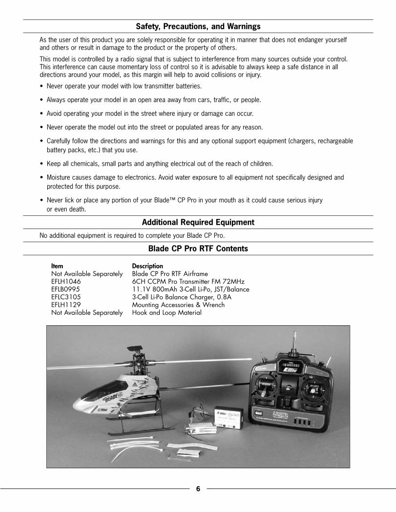
Blade CP Pro RTF Contents
Item DescriptionNot Available Separately Blade CP Pro RTF AirframeEFLH1046 6CH CCPM Pro Transmitter FM 72MHzEFLB0995 11.1V 800mAh 3-Cell Li-Po, JST/BalanceEFLC3105 3-Cell Li-Po Balance Charger, 0.8AEFLH1129 Mounting Accessories & WrenchNot Available Separately Hook and Loop Material
�
Battery Warnings, Guidelines and Charging
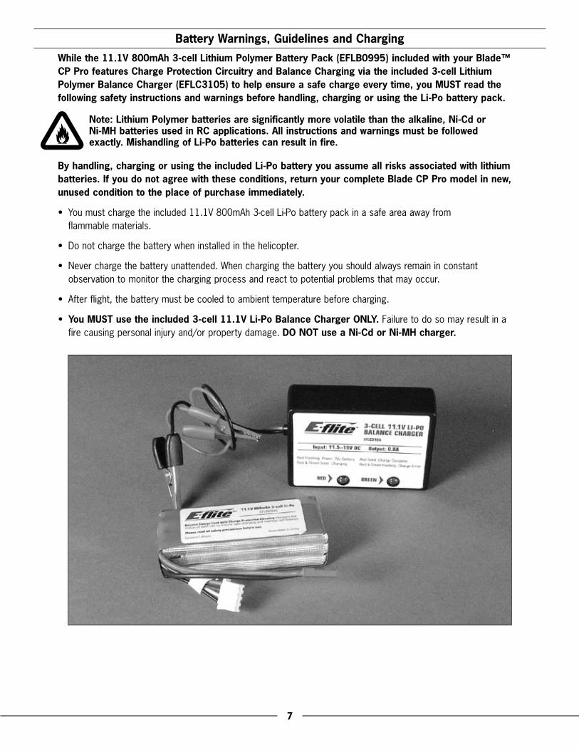
While the 11.1V 800mAh �-cell Lithium Polymer Battery Pack (EFLB099�) included with your Blade™ CP Pro features Charge Protection Circuitry and Balance Charging via the included �-cell Lithium Polymer Balance Charger (EFLC�10�) to help ensure a safe charge every time, you MUST read the following safety instructions and warnings before handling, charging or using the Li-Po battery pack.
Note: Lithium Polymer batteries are significantly more volatile than the alkaline, Ni-Cd or Ni-MH batteries used in RC applications. All instructions and warnings must be followed exactly. Mishandling of Li-Po batteries can result in fire.
By handling, charging or using the included Li-Po battery you assume all risks associated with lithium batteries. If you do not agree with these conditions, return your complete Blade CP Pro model in new, unused condition to the place of purchase immediately.
•. You.must.charge.the.included.11 .1V.800mAh.3-cell.Li-Po.battery.pack.in.a.safe.area.away.from..flammable.materials .
•. Do.not.charge.the.battery.when.installed.in.the.helicopter .
•. Never.charge.the.battery.unattended ..When.charging.the.battery.you.should.always.remain.in.constant.observation.to.monitor.the.charging.process.and.react.to.potential.problems.that.may.occur .
•. After.flight,.the.battery.must.be.cooled.to.ambient.temperature.before.charging .
•. You MUST use the included �-cell 11.1V Li-Po Balance Charger ONLY..Failure.to.do.so.may.result.in.a.fire.causing.personal.injury.and/or.property.damage ..DO NOT use a Ni-Cd or Ni-MH charger.
8
•. If.at.any.time.during.the.charge.or.discharge.process.the.battery.begins.to.balloon.or.swell,.discontinue.charging.or.discharging.immediately ..Quickly.and.safely.disconnect.the.battery,.then.place.it.in.a.safe,.open.area.away.from.flammable.materials.to.observe.it.for.at.least.15.minutes ..Continuing.to.charge.or.discharge.a.battery.that.has.begun.to.balloon.or.swell.can.result.in.a.fire ..A.battery.that.has.ballooned.or.swollen.even.a.small.amount.must.be.removed.from.service.completely .
•. In.the.event.of.a.crash,.you.must.quickly.and.safely.disconnect.and.remove.the.battery.from.the.model,.then.place.it.in.a.safe,.open.area.away.from.flammable.materials.to.observe.it.for.at.least.15.minutes .
•. Store.the.battery.at.room.temperature.for.best.results .
•. When.transporting.or.temporarily.storing.the.battery,.the.temperature.range.should.be.from.40–120.degrees.Fahrenheit ..Do.not.store.the.battery.or.model.in.a.car.or.direct.sunlight.whenever.possible ..If.stored.in.a.hot.car,.the.battery.can.be.damaged.or.even.cause.a.fire .
• Do not over-discharge the battery. Discharging the battery too low can cause damage to the pack resulting in reduced performance and duration.
Li-Po cells should not be discharged to below �V each under load. In the case of the �-Cell Li-Po packs used for the Blade™ CP Pro, you will not want to allow the battery to fall to below 9V during flight.
The Blade CP Pro �-in-1 control unit does not feature a voltage cutoff of any type, so we suggest that you be extremely aware of the power level of the Li-Po battery pack. If at any time the helicopter begins to require more throttle than typical to maintain hover or flight, or has lost significant power, you must land the helicopter and power the motors down IMMEDIATELY to prevent over-discharge of the Li-Po battery pack. If you continue to run the motors after noticing a loss in power, it is possible to discharge the Li-Po battery pack too far, causing permanent damage to the pack. Over-discharge of the Li-Po battery pack can result in shortened flight times, loss of power output or failure of the pack entirely.
If.you.have.any.further.questions.or.concerns.regarding.the.handling,.charging.and/or.use.of.the.included.Li-Po.battery.pack,.please.contact.Horizon.Hobby’s.Product.Support.staff.at.1-877-504-0233 .

9
It is important that you only charge the included 11.1V 800mAh �-cell Li-Po Battery Pack (EFLB099�) with the included �-cell 11.1V Li-Po Balance Charger (EFLC�10�). Your battery pack is equipped with special Charge Protection Circuitry and a Balance Charge Lead with connector that is only compatible with this charger. Attempting to charge the pack using another Li-Po charger or non Li-Po compatible charger could result in serious damage. Please familiarize yourself thoroughly with the warnings and guidelines (pages �–8) before continuing.
The.included.3-cell.11 .1V.Li-Po.Balance.Charger.will.charge.a.near.fully.discharged.(not.over-discharged)..11 .1V.800mAh.3-cell.Li-Po.Battery.Pack.in.approximately.1 .0–1 .5.hours ..In.some.cases.the.charge.time..may.be.shorter.depending.on.the.actual.amount.of.capacity.left.in.the.pack.after.a.flight ..NEVER charge the battery unattended.
Note:.The.Li-Po.battery.pack.included.with.your.Blade™.CP.Pro.will.arrive.partially.charged ..For.this.reason.the.initial.charge.may.only.take.approximately.30–50.minutes .
The.charger.requires.up.to.1 .5.Amps.of.11 .5–15.Volt.DC.input.power.that.can.be.supplied.from.a.small.12V.gel.cell.or.car.battery .

10
Input.power.for.the.charger.can.also.be.supplied.through.the.use.of.an.AC.to.DC.adapter/power.supply.for.convenient.charging.anywhere.an.AC.outlet.is.available ..We.recommend.the.optional.E-flite®.AC.to.12V.DC,..1 .5-Amp.Power.Supply.(EFLC4000) . NEVER attempt to power the charger from an AC outlet without the use of a proper AC to DC adapter/power supply.
Note:.When.using.the.AC.to.DC.adapter/power.supply,.the.charger.is.protected.to.prevent.damage.if.the.alligator.clips.touch ..However,.please.take.care.to.ensure.that.the.alligator.clips.do.not.cause.shorting.of.the.battery,.adapter/power.supply,.etc ..by.keeping.them.clear .
The.charger.is.equipped.with.two.LED.indicators.marked.RED.and.GREEN.on.the.label ..These.LEDs.indicate.the.following.(also.found.on.the.label.of.the.charger):
• Red Flashing LED Only:.Input.power.with.no.battery.connected
•. Red and Green Solid LED:.Battery.connected.and.charging
•. Red Solid LED Only:.Charge.complete
•. Red and Green Flashing LED:.Charge.error
11
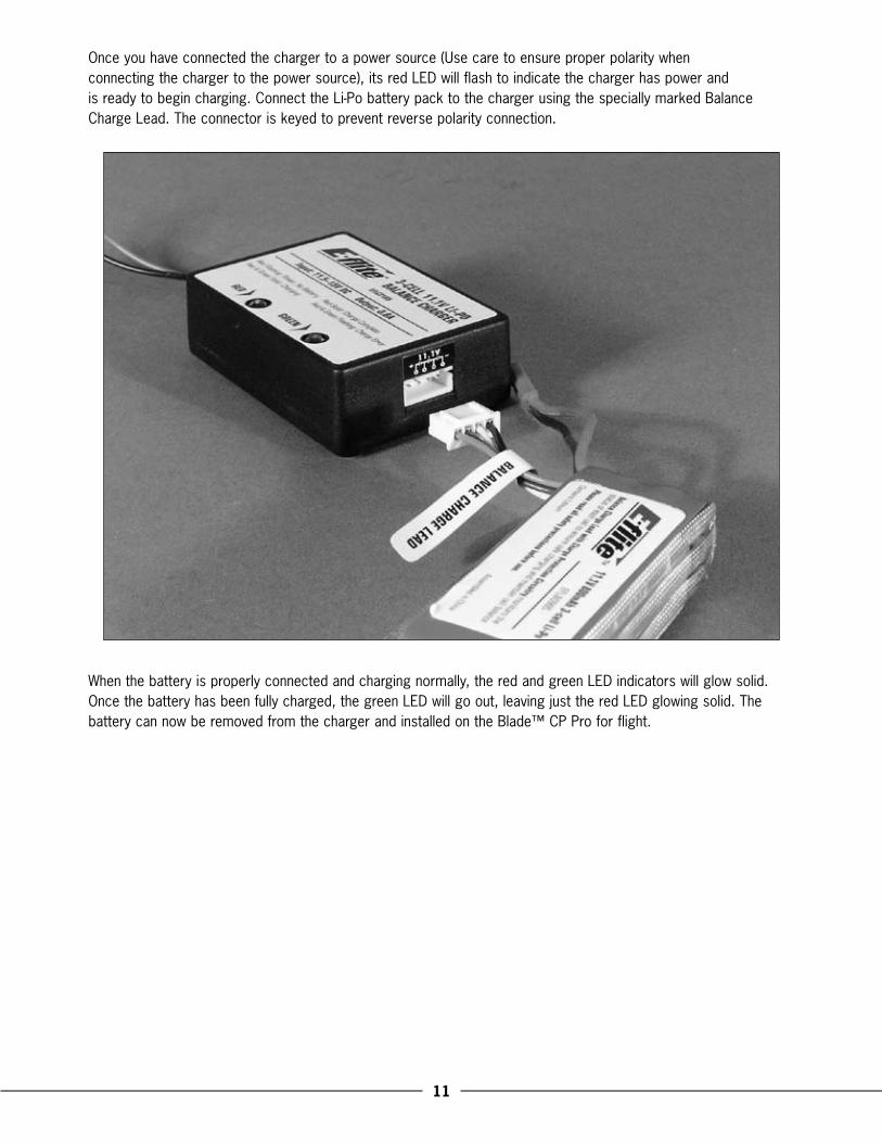
Once.you.have.connected.the.charger.to.a.power.source.(Use.care.to.ensure.proper.polarity.when..connecting.the.charger.to.the.power.source),.its.red.LED.will.flash.to.indicate.the.charger.has.power.and..is.ready.to.begin.charging ..Connect.the.Li-Po.battery.pack.to.the.charger.using.the.specially.marked.Balance.Charge.Lead ..The.connector.is.keyed.to.prevent.reverse.polarity.connection .
When.the.battery.is.properly.connected.and.charging.normally,.the.red.and.green.LED.indicators.will.glow.solid ..Once.the.battery.has.been.fully.charged,.the.green.LED.will.go.out,.leaving.just.the.red.LED.glowing.solid ..The.battery.can.now.be.removed.from.the.charger.and.installed.on.the.Blade™.CP.Pro.for.flight .
1�
Charge Errors and Indications
In the event that both the red and green LEDs flash, a charge error has occurred. Some examples of charge errors and their indications include:
•. Alternating.flashing.of.the.red.and.green.LEDs.will.indicate.that.the.charge.process.has.been.interrupted ..If.input.power.to.the.charger.has.been.interrupted.due.to.disconnection.from.the.power.source.or.a.drop.in.voltage/current.output.from.the.power.source,.unplug.the.battery.from.the.charger ..Next,.check.to.make.sure.that.the.alligator.clips.are.firmly.and.properly.attached.to.the.power.source.or.that.the.input.power.plug.from.the.optional.AC.to.12V.DC.adapter/power.supply.is.connected ..Also.be.sure.that.the.power.source.is.providing.the.proper.amount.of.voltage.and.current.required.to.the.charger .
•. After.confirming.the.connections.and.that.the.power.source.is.delivering.the.necessary.voltage.and.current,.re-start.the.charge.process.by.connecting.the.battery.pack ..Continue.to.monitor.the.charge.process.to.ensure.that.no.further.charge.errors.occur .
•. Simultaneous.flashing.of.the.red.and.green.LEDs.will.indicate.that.the.voltage.of.the.Li-Po.battery.pack.is.too.low.to.allow.the.charge.process.to.begin ..In.this.case.the.battery.may.have.been.over-discharged.due.to.flying.the.model.too.long.(For.more.information.on.preventing.over-discharge.of.the.Li-Po.battery.pack,.see.the.guidelines.section.found.on.page.8),.or.that.a.single.cell.or.even.all.cells.in.the.battery.pack.may.be.damaged .
If after several charging attempts you continue to see this charge error indication, you should remove the battery pack from service and replace it with a new one.
If.you.have.any.further.questions.or.concerns.regarding.charge.error.indications,.please.contact.Horizon.Hobby’s.Product.Support.staff.at.1-877-504-0233 .
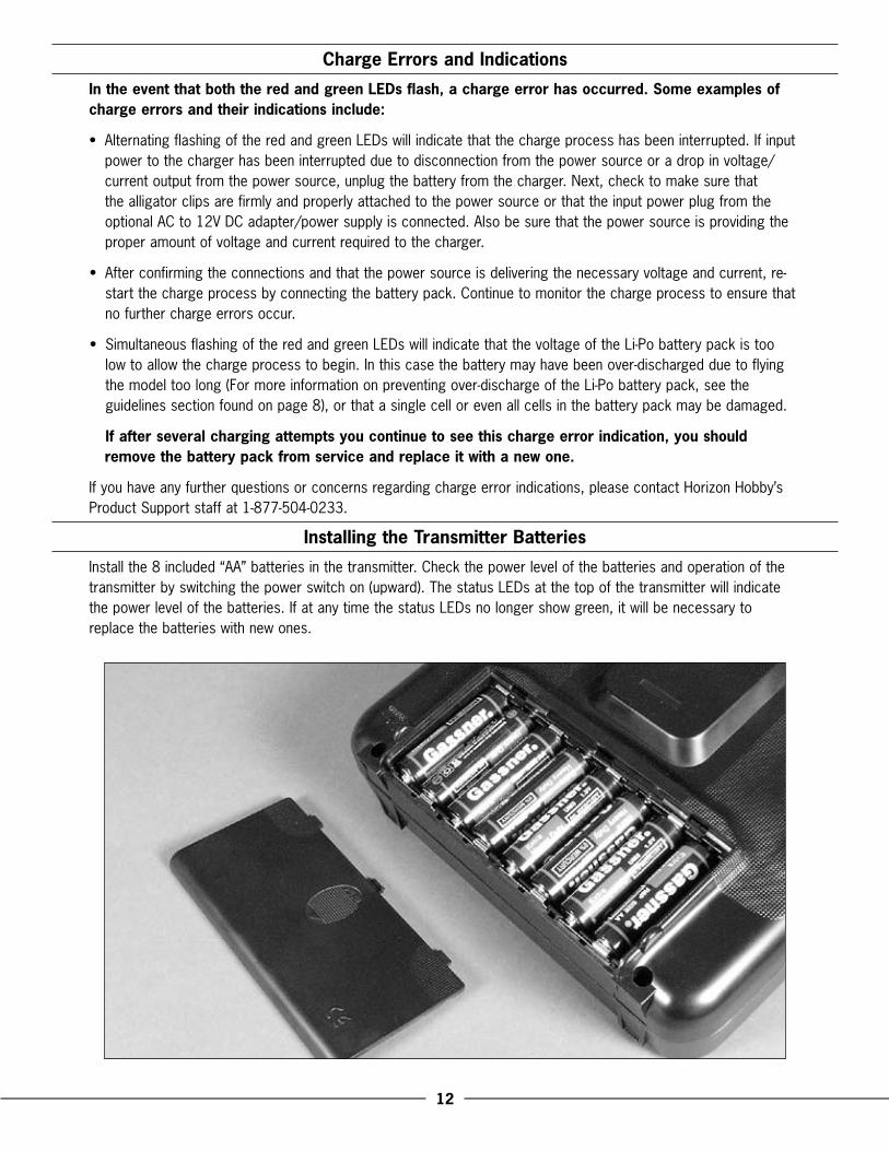
Installing the Transmitter Batteries
Install.the.8.included.“AA”.batteries.in.the.transmitter ..Check.the.power.level.of.the.batteries.and.operation.of.the.transmitter.by.switching.the.power.switch.on.(upward) ..The.status.LEDs.at.the.top.of.the.transmitter.will.indicate.the.power.level.of.the.batteries ..If.at.any.time.the.status.LEDs.no.longer.show.green,.it.will.be.necessary.to.replace.the.batteries.with.new.ones .
1�
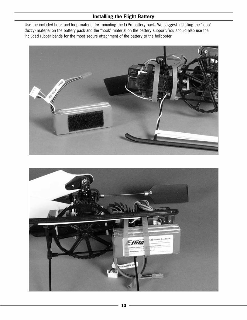
Installing the Flight Battery
Use.the.included.hook.and.loop.material.for.mounting.the.Li-Po.battery.pack ..We.suggest.installing.the.“loop”.(fuzzy).material.on.the.battery.pack.and.the.“hook”.material.on.the.battery.support ..You.should.also.use.the.included.rubber.bands.for.the.most.secure.attachment.of.the.battery.to.the.helicopter .
1�
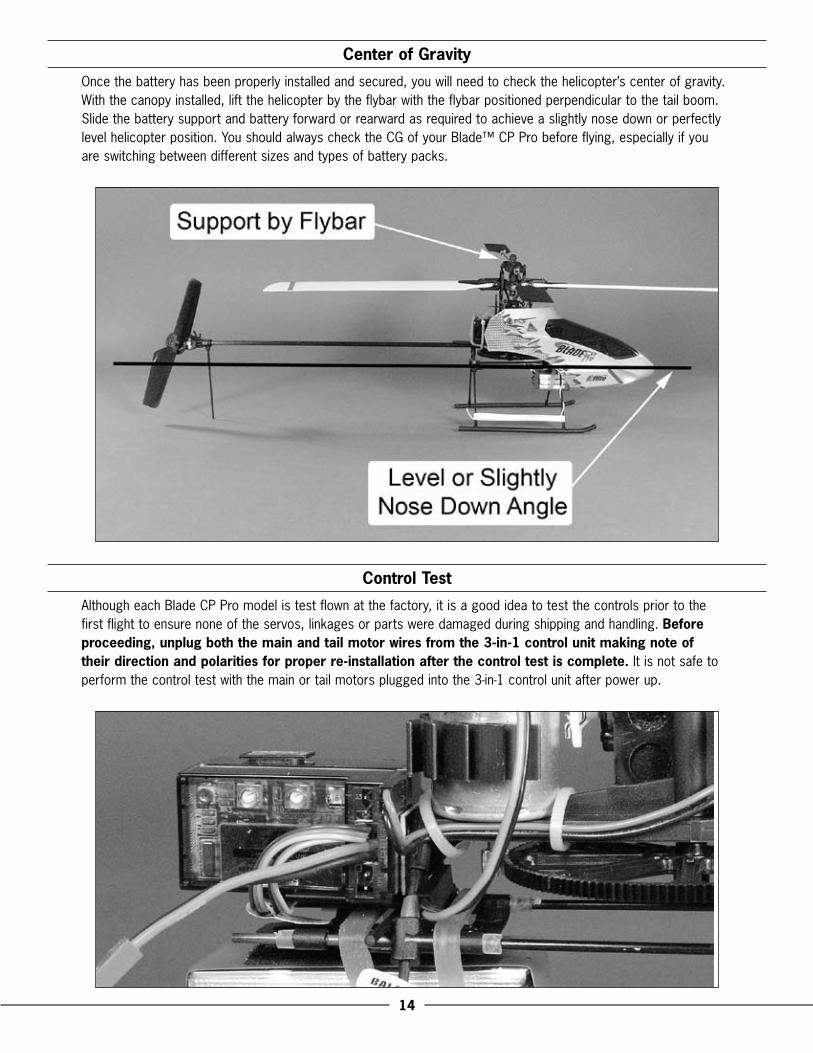
Center of Gravity
Once.the.battery.has.been.properly.installed.and.secured,.you.will.need.to.check.the.helicopter’s.center.of.gravity ..With.the.canopy.installed,.lift.the.helicopter.by.the.flybar.with.the.flybar.positioned.perpendicular.to.the.tail.boom ..Slide.the.battery.support.and.battery.forward.or.rearward.as.required.to.achieve.a.slightly.nose.down.or.perfectly.level.helicopter.position ..You.should.always.check.the.CG.of.your.Blade™.CP.Pro.before.flying,.especially.if.you.are.switching.between.different.sizes.and.types.of.battery.packs .
Control Test
Although.each.Blade.CP.Pro.model.is.test.flown.at.the.factory,.it.is.a.good.idea.to.test.the.controls.prior.to.the.first.flight.to.ensure.none.of.the.servos,.linkages.or.parts.were.damaged.during.shipping.and.handling ..Before proceeding, unplug both the main and tail motor wires from the �-in-1 control unit making note of their direction and polarities for proper re-installation after the control test is complete..It.is.not.safe.to.perform.the.control.test.with.the.main.or.tail.motors.plugged.into.the.3-in-1.control.unit.after.power.up .
1�
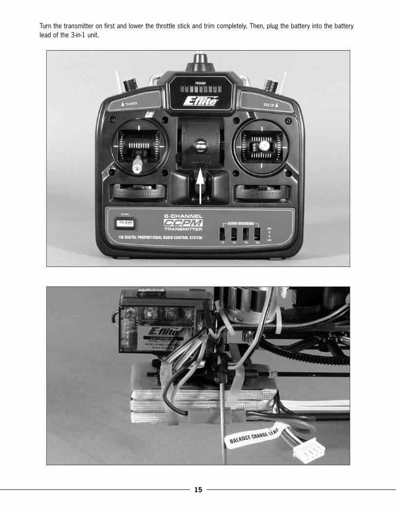
Turn.the.transmitter.on.first.and.lower.the.throttle.stick.and.trim.completely ..Then,.plug.the.battery.into.the.battery.lead.of.the.3-in-1.unit .
1�
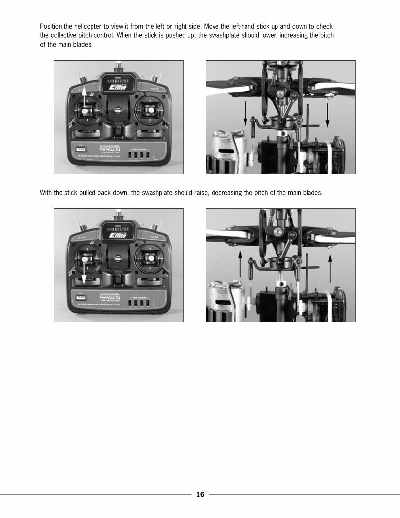
Position.the.helicopter.to.view.it.from.the.left.or.right.side ..Move.the.left-hand.stick.up.and.down.to.check..the.collective.pitch.control ..When.the.stick.is.pushed.up,.the.swashplate.should.lower,.increasing.the.pitch..of.the.main.blades ..
With.the.stick.pulled.back.down,.the.swashplate.should.raise,.decreasing.the.pitch.of.the.main.blades .
1�
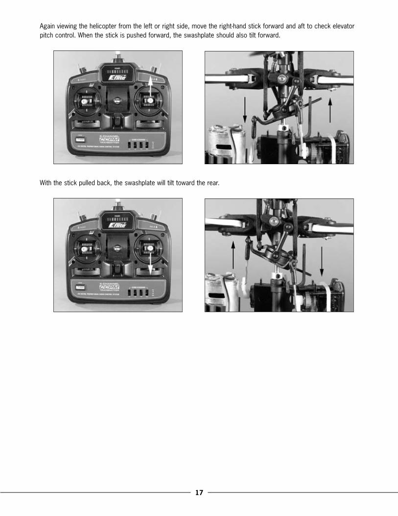
Again.viewing.the.helicopter.from.the.left.or.right.side,.move.the.right-hand.stick.forward.and.aft.to.check.elevator.pitch.control ..When.the.stick.is.pushed.forward,.the.swashplate.should.also.tilt.forward ..
With.the.stick.pulled.back,.the.swashplate.will.tilt.toward.the.rear .
18
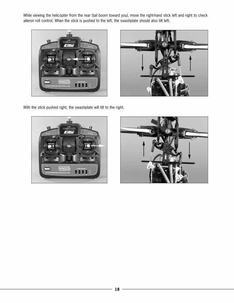
While.viewing.the.helicopter.from.the.rear.(tail.boom.toward.you),.move.the.right-hand.stick.left.and.right.to.check.aileron.roll.control ..When.the.stick.is.pushed.to.the.left,.the.swashplate.should.also.tilt.left .
With.the.stick.pushed.right,.the.swashplate.will.tilt.to.the.right .
19
If.at.any.time.during.the.test.the.controls.do.not.respond.properly,.double-check.the.servo.reversing.switches.on.the.transmitter ..They.should.be.positioned.as.follows:
AIL. –. NORELE. –. REVTHR. –. NORRUD.–. REV
If.the.controls.still.do.not.respond.properly.after.ensuring.the.servo.reversing.switch.positions.are.correct,.you.may.also.check.the.servo.connections.to.the.receiver ..These.should.be.positioned.as.follows.(when.viewing.the.helicopter.from.behind):
Channel 1..–..Right-hand.rear.“aileron”.servoChannel �..–..Forward.“elevator”.servoChannel �..–..Left-hand.rear.“pitch”.servo
Once.you.have.confirmed.proper.reversing.switch.and.servo.connection.locations,.all.controls.should.be.functioning.properly ..If.you.do.encounter.any.problems.with.your.Blade™.CP.Pro.responding.properly.to.the.transmitter,.do.not.fly ..Call.Horizon’s.Product.Support.staff.at.1-877-504-0233 .
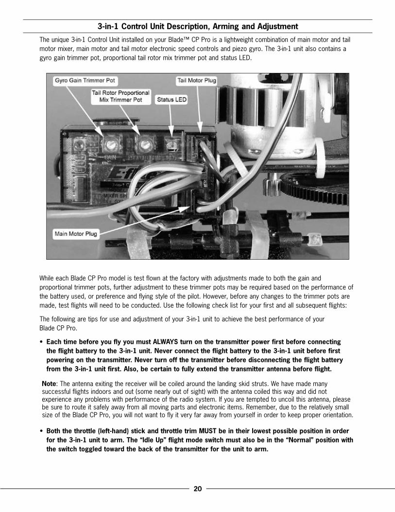
If.you.have.confirmed.proper.control.operation.of.your.Blade.CP.Pro,.reconnect.the.main.and.tail.motor.wires.to.the.3-in-1.unit,.taking.care.to.keep.the.proper.polarity.and.location.of.each.as.they.were.before.the.test ..The.tail.motor.plug.should.be.installed.into.the.upper.output.slot.of.the.3-in-1.control.unit.with.the.positive.lead.to.the.top ..The.main.motor.plug.should.be.installed.into.the.lower.output.slot.with.the.positive.lead.to.the.bottom ..Please.see.the.photo.found.on.page.20.for.reference .
�0
�-in-1 Control Unit Description, Arming and Adjustment
The.unique.3-in-1.Control.Unit.installed.on.your.Blade™.CP.Pro.is.a.lightweight.combination.of.main.motor.and.tail.motor.mixer,.main.motor.and.tail.motor.electronic.speed.controls.and.piezo.gyro ..The.3-in-1.unit.also.contains.a.gyro.gain.trimmer.pot,.proportional.tail.rotor.mix.trimmer.pot.and.status.LED .
While.each.Blade.CP.Pro.model.is.test.flown.at.the.factory.with.adjustments.made.to.both.the.gain.and.proportional.trimmer.pots,.further.adjustment.to.these.trimmer.pots.may.be.required.based.on.the.performance.of.the.battery.used,.or.preference.and.flying.style.of.the.pilot ..However,.before.any.changes.to.the.trimmer.pots.are.made,.test.flights.will.need.to.be.conducted ..Use.the.following.check.list.for.your.first.and.all.subsequent.flights:
The.following.are.tips.for.use.and.adjustment.of.your.3-in-1.unit.to.achieve.the.best.performance.of.your..Blade.CP.Pro .
•. Each time before you fly you must ALWAYS turn on the transmitter power first before connecting the flight battery to the �-in-1 unit. Never connect the flight battery to the �-in-1 unit before first powering on the transmitter. Never turn off the transmitter before disconnecting the flight battery from the �-in-1 unit first. Also, be certain to fully extend the transmitter antenna before flight.
Note:.The.antenna.exiting.the.receiver.will.be.coiled.around.the.landing.skid.struts ..We.have.made.many.successful.flights.indoors.and.out.(some.nearly.out.of.sight).with.the.antenna.coiled.this.way.and.did.not.experience.any.problems.with.performance.of.the.radio.system ..If.you.are.tempted.to.uncoil.this.antenna,.please.be.sure.to.route.it.safely.away.from.all.moving.parts.and.electronic.items ..Remember,.due.to.the.relatively.small.size.of.the.Blade.CP.Pro,.you.will.not.want.to.fly.it.very.far.away.from.yourself.in.order.to.keep.proper.orientation .
•. Both the throttle (left-hand) stick and throttle trim MUST be in their lowest possible position in order for the �-in-1 unit to arm. The “Idle Up” flight mode switch must also be in the “Normal” position with the switch toggled toward the back of the transmitter for the unit to arm.

�1
•. If.this.is.the.first.test.flight,.or.a.test.flight.following.repairs,.you.will.also.want.to.center.the.rudder,.aileron..and.elevator.trims .
•. Once.confirming.the.transmitter.has.been.turned.on.and.has.an.adequate.level.of.battery.power.as.displayed.by.the.LEDs.at.the.top.of.the.transmitter,.it.is.now.safe.to.plug.the.flight.battery.to.the.3-in-1.unit .
•. With battery power applied, the �-in-1 unit status LED will blink red, then blink green. It is extremely important that during this time of calibration the helicopter is not moved or swayed in order for the gyro to properly initialize. If.the.helicopter.was.moved.or.swayed.during.this.time,.unplug.the.flight.battery.and.repeat.the.initialization.process .
•. When.the.status.LED.becomes.solid.green,.the.unit.is.armed.and.ready.for.flight ..Use.caution.as.both.the.main.and.tail.rotors.will.now.run.with.throttle.stick.input ..For.safety,.once.the.unit.is.armed,.the.main.and.tail.motors.will.not.run.with.the.throttle.stick.and.trim.in.their.lowest.positions ..Do.not.advance.the.throttle.stick.until.you.are.clear.of.the.rotor.blades.and.ready.to.fly .
Note: If the status LED does not become solid green, please review the following:
•. If.after.blinking.red.the.status.LED.becomes.solid.red,.you.have.a.positive.Radio.Frequency.(RF).link.between.the.transmitter.and.receiver/3-in-1.unit,.but.the.throttle.stick.and.throttle.trim.may.not.be.in.their.lowest.possible.positions ..Check.to.be.sure.that.both.the.throttle.stick.and.throttle.trim.are.in.their.lowest.possible.position.and.the.status.LED.should.blink.green.then.become.solid.green.indicating.the.unit.is.armed.and.ready.for.flight ..Proceed.to.the.next.step.of.the.checklist.once.the.unit.is.armed .
•. If.after.blinking.red.the.status.LED.continues.to.flash.from.green.to.red,.you.do.not.have.a.positive.RF.link.between.the.transmitter.and.receiver/3-in-1.unit ..First,.check.to.be.sure.that.the.transmitter.has.been.powered.on.and.has.an.adequate.level.of.battery.power ..If.the.transmitter.was.indeed.powered.on,.power.both.the.transmitter.and.3-in-1.unit.down,.then.check.that.the.crystal.in.the.transmitter.and.the.crystal.in.the.receiver..are.properly.seated.and.secured.in.their.mounts ..Once.you.have.confirmed.the.crystals.are.properly.seated..and.secured,.turn.on.the.transmitter.and.then.connect.the.flight.battery.to.the.3-in-1.unit ..The.3-in-1.unit.should.now.arm.normally .
If.your.3-in-1.unit.will.not.arm.after.following.the.guidelines.as.listed.above,.contact.Horizon.Hobby’s.Product.Support.staff.at.1-877-504-0233 .
•. Once.you.have.placed.the.helicopter.in.a.safe.place.to.fly,.free.of.obstructions,.and.are.clear.of.the.rotor.blades,.you.can.safely.power.up.the.model .
Note: If this is your first test flight, the model should not be flown indoors unless it is in a very large area such as a gym. Until you have properly trimmed, adjusted and become familiar with the handling of the Blade™ CP Pro, we suggest your first and any subsequent test flights be made outdoors in calm air only.
•. Advance.the.throttle.stick.slowly,.just.until.both.the.main.and.tail.rotor.blades.begin.to.spin ..Note.the.direction.that.the.main.and.tail.rotor.blades.spin ..The.main.rotor.blades.should.spin.clockwise.when.viewed.from.the.top,.with.the.tail.rotor.blade.spinning.counterclockwise.when.viewed.from.the.right-hand.side.of.the.helicopter ..If.either.set.of.rotor.blades.is.operating.in.the.wrong.direction,.unplug.the.battery,.and.then.simply.reverse.its.motor.wire.plug.polarity.on.the.3-in-1.unit .

��
•. Once.the.tail.rotor.has.begun.to.spin,.and.before.lifting.off,.it.is.best.to.check.that.the.tail.rotor.is.responding.properly.to.transmitter.inputs ..When.inputting.a.slight.amount.of.right.rudder,.the.tail.rotor.rpms.should.increase,.pushing.the.nose.of.the.helicopter.to.the.right ..If.you.are.on.carpet,.grass,.or.an.otherwise.uneven.surface,.be.very.careful.not.to.allow.the.helicopter.to.catch.the.vertical.tail.support.or.tail.rotor.blade.when.testing.the.tail.rotor.control.on.the.ground.or.during.liftoff .
•. If.both.rotor.directions.are.correct,.and.the.tail.rotor.is.responding.properly.to.rudder.inputs,.you.can.now.lift.your.Blade™.CP.into.hover.to.check.gyro.gain.and.tail.rotor.proportional.mix .
Note:.The.throttle.trim.can.be.used.to.adjust.the.throttle.and.collective.pitch.values.for.a.given.throttle.stick.position ..For.example,.raising.the.throttle.trim.will.allow.the.model.to.hover.at.a.lower.throttle.stick.position .
If.you.find.your.model.will.not.lift.off.the.ground.with.the.throttle.stick.in.the.highest.position,.increasing.the.throttle.trim.will.add.collective.pitch ..(You.can.also.increase.the.pitch.of.the.blades.by.adjusting.the.Pitch.Control.Links ..See.the.“Pitch.Curve.Adjustments”.section.on.page.30.of.this.manual.for.more.information .)
Note: While the �-in-1 control unit main motor and tail motor ESCs are readily capable of handling all in-flight power loads, and even brief momentary bursts beyond these typical loads, they can be damaged if excessive amounts of current are pulled through them for an extended period of time. This period of time may vary depending on conditions, so it is best to keep any momentary overloads as short as possible in order to prevent damage to the �-in-1 ESCs.
In the event of a crash, regardless of how minor or major, you MUST throttle back both the main and tail motors as quickly as possible. If a crash occurs when flying in Normal Mode (with the throttle trim increased any amount beyond the lowest setting), you will need to lower the throttle/collective stick AND throttle/collective trim immediately to prevent damage to the ESCs. If a crash occurs when flying in the Idle Up flight mode, you will need to switch back to Normal Mode while also lowering the throttle/collective stick and trim immediately to prevent damage to the ESCs.

��
Tail Rotor Proportional Mix Trimmer Pot Description and Adjustment
After.establishing.a.stable.hover,.you.will.first.want.to.adjust.the.tail.rotor.proportional.mixing ..The.“proportional”.trimmer.pot.adjusts.the.amount.of.tail.motor.to.main.motor.mixing .
•. In.hover,.with.the.rudder.trim.centered.and.no.rudder.input,.note.which.direction.the.nose.of.the.helicopter.is.trying.to.spin ..If.the.nose.of.the.helicopter.is.spinning.to.the.left,.you.will.want.to.increase.the.amount.of.tail.motor.to.main.motor.mixing ..By.turning.the.proportional.trimmer.pot.clockwise.(+),.you.increase.the.tail.motor/rotor.rpm.for.a.given.main.motor/rotor.rpm ..This.increase.in.tail.motor/rotor.rpm.will.help.to.push.the.nose.of.the.helicopter.to.the.right.when.in.hover .
. If.the.nose.of.the.helicopter.is.trying.to.spin.to.the.right.in.hover,.decrease.the.tail.rotor.proportional.mix.by.turning.the.proportional.trimmer.pot.counterclockwise.(-) .
Note: You must always power down the �-in-1 control unit before making adjustments to the proportional mix trimmer pot. Any changes made to the trimmer pot will not take effect until the �-in-1 unit is initialized and re-armed.
•. As.the.battery.output.voltage.decreases.throughout.the.flight,.it.may.be.necessary.to.make.small.trim.adjustments.to.the.rudder.in.order.to.keep.the.nose.of.the.helicopter.straight ..Usually.a.few.clicks.of.right.rudder.may.be.required,.and.no.further.adjustment.of.the.proportional.trimmer.pot.will.be.necessary ..
Note:.More.experienced.pilots.may.choose.to.adjust.the.proportional.mix.to.better.hold.the.tail.during.aggressive.climb.outs.and.aerobatics.rather.than.in.hover.only .
•. The.amount.of.tail.rotor.proportional.mix.required.may.vary.depending.on.the.performance.of.a.given.flight.battery ..For.example,.when.switching.from.lower.capacity.and/or.discharge.rate.capable.packs.to.higher.capacity.and/or.discharge.capable.packs,.some.small.adjustments.to.the.proportional.mix.may.be.required ..To.help.prevent.the.need.for.additional.adjustment.of.the.proportional.mix.when.switching.between.battery.packs,.we.suggest.using.the.same.make,.model.and.performance.packs.only .
��
Gyro Gain Trimmer Pot Description and Adjustment
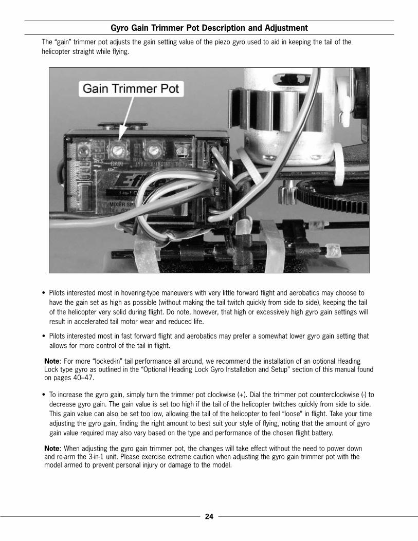
The.“gain”.trimmer.pot.adjusts.the.gain.setting.value.of.the.piezo.gyro.used.to.aid.in.keeping.the.tail.of.the.helicopter.straight.while.flying .
•. Pilots.interested.most.in.hovering-type.maneuvers.with.very.little.forward.flight.and.aerobatics.may.choose.to.have.the.gain.set.as.high.as.possible.(without.making.the.tail.twitch.quickly.from.side.to.side),.keeping.the.tail.of.the.helicopter.very.solid.during.flight ..Do.note,.however,.that.high.or.excessively.high.gyro.gain.settings.will.result.in.accelerated.tail.motor.wear.and.reduced.life .
•. Pilots.interested.most.in.fast.forward.flight.and.aerobatics.may.prefer.a.somewhat.lower.gyro.gain.setting.that.allows.for.more.control.of.the.tail.in.flight .
Note:.For.more.“locked-in”.tail.performance.all.around,.we.recommend.the.installation.of.an.optional.Heading.Lock.type.gyro.as.outlined.in.the.“Optional.Heading.Lock.Gyro.Installation.and.Setup”.section.of.this.manual.found.on.pages.40–47 .
•. To.increase.the.gyro.gain,.simply.turn.the.trimmer.pot.clockwise.(+) ..Dial.the.trimmer.pot.counterclockwise.(-).to.decrease.gyro.gain ..The.gain.value.is.set.too.high.if.the.tail.of.the.helicopter.twitches.quickly.from.side.to.side ..This.gain.value.can.also.be.set.too.low,.allowing.the.tail.of.the.helicopter.to.feel.“loose”.in.flight ..Take.your.time.adjusting.the.gyro.gain,.finding.the.right.amount.to.best.suit.your.style.of.flying,.noting.that.the.amount.of.gyro.gain.value.required.may.also.vary.based.on.the.type.and.performance.of.the.chosen.flight.battery .
Note:.When.adjusting.the.gyro.gain.trimmer.pot,.the.changes.will.take.effect.without.the.need.to.power.down.and.re-arm.the.3-in-1.unit ..Please.exercise.extreme.caution.when.adjusting.the.gyro.gain.trimmer.pot.with.the.model.armed.to.prevent.personal.injury.or.damage.to.the.model .
��
Normal and Idle Up Flight Modes
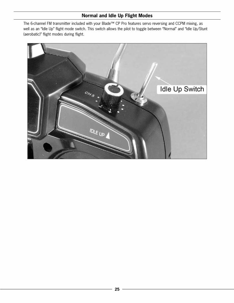
The.6-channel.FM.transmitter.included.with.your.Blade™.CP.Pro.features.servo.reversing.and.CCPM.mixing,.as.well.as.an.“Idle.Up”.flight.mode.switch ..This.switch.allows.the.pilot.to.toggle.between.“Normal”.and.“Idle.Up/Stunt.(aerobatic)”.flight.modes.during.flight .
��
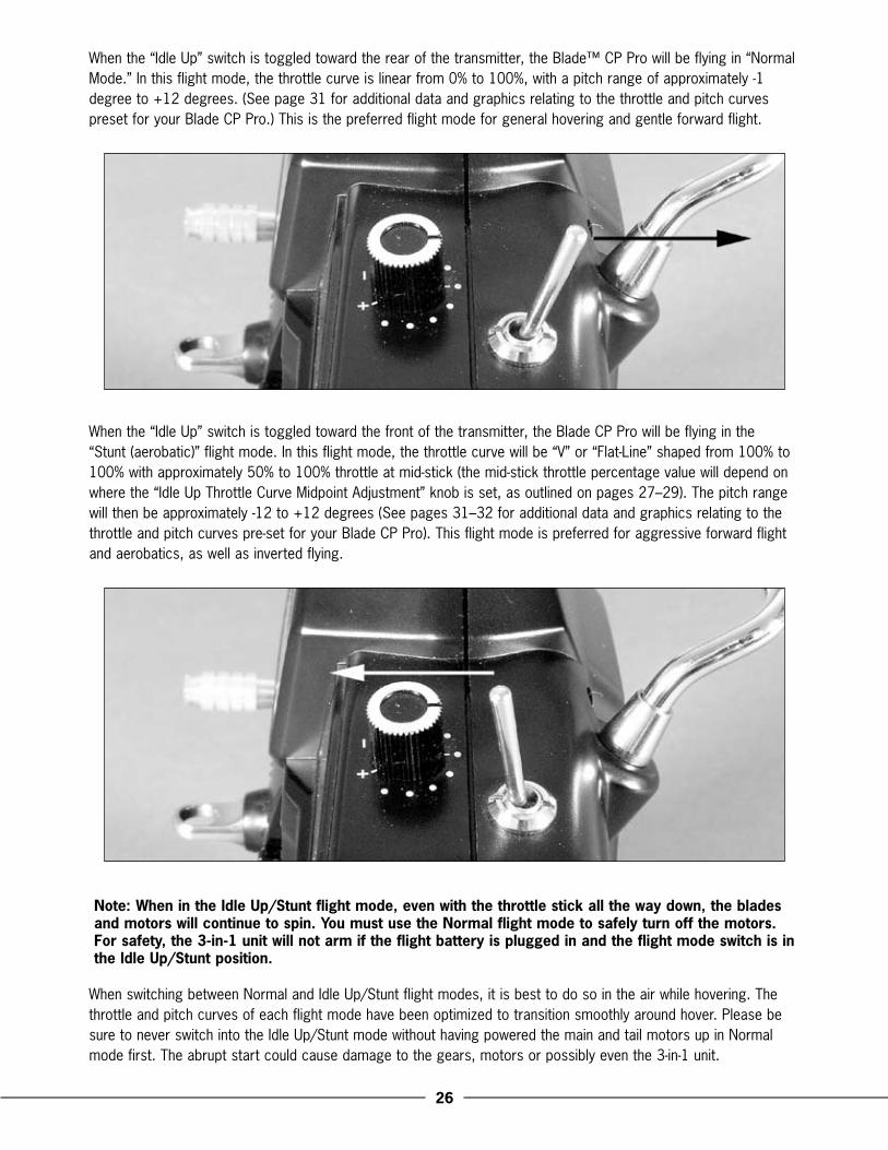
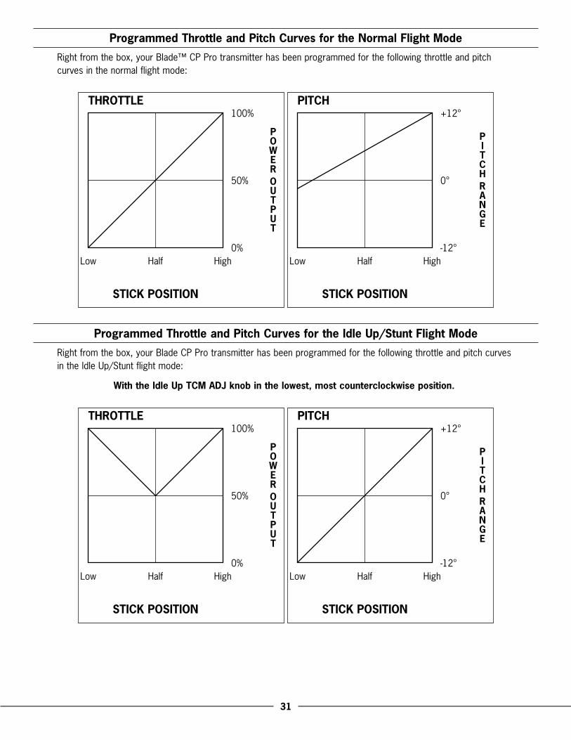
When.the.“Idle.Up”.switch.is.toggled.toward.the.rear.of.the.transmitter,.the.Blade™.CP.Pro.will.be.flying.in.“Normal.Mode .”.In.this.flight.mode,.the.throttle.curve.is.linear.from.0%.to.100%,.with.a.pitch.range.of.approximately.-1.degree.to.+12.degrees ..(See.page.31.for.additional.data.and.graphics.relating.to.the.throttle.and.pitch.curves.preset.for.your.Blade.CP.Pro .).This.is.the.preferred.flight.mode.for.general.hovering.and.gentle.forward.flight .
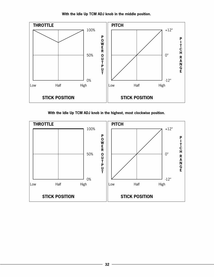
When.the.“Idle.Up”.switch.is.toggled.toward.the.front.of.the.transmitter,.the.Blade.CP.Pro.will.be.flying.in.the.“Stunt.(aerobatic)”.flight.mode ..In.this.flight.mode,.the.throttle.curve.will.be.“V”.or.“Flat-Line”.shaped.from.100%.to.100%.with.approximately.50%.to.100%.throttle.at.mid-stick.(the.mid-stick.throttle.percentage.value.will.depend.on.where.the.“Idle.Up.Throttle.Curve.Midpoint.Adjustment”.knob.is.set,.as.outlined.on.pages.27–29) ..The.pitch.range.will.then.be.approximately.-12.to.+12.degrees.(See.pages.31–32.for.additional.data.and.graphics.relating.to.the.throttle.and.pitch.curves.pre-set.for.your.Blade.CP.Pro) ..This.flight.mode.is.preferred.for.aggressive.forward.flight.and.aerobatics,.as.well.as.inverted.flying .
Note: When in the Idle Up/Stunt flight mode, even with the throttle stick all the way down, the blades and motors will continue to spin. You must use the Normal flight mode to safely turn off the motors. For safety, the �-in-1 unit will not arm if the flight battery is plugged in and the flight mode switch is in the Idle Up/Stunt position.
When.switching.between.Normal.and.Idle.Up/Stunt.flight.modes,.it.is.best.to.do.so.in.the.air.while.hovering ..The.throttle.and.pitch.curves.of.each.flight.mode.have.been.optimized.to.transition.smoothly.around.hover ..Please.be.sure.to.never.switch.into.the.Idle.Up/Stunt.mode.without.having.powered.the.main.and.tail.motors.up.in.Normal.mode.first ..The.abrupt.start.could.cause.damage.to.the.gears,.motors.or.possibly.even.the.3-in-1.unit .
��
Idle Up Throttle Curve Midpoint Adjustment Knob Description and Adjustment
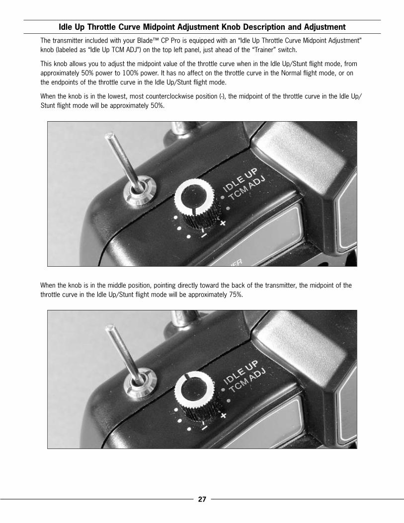
The.transmitter.included.with.your.Blade™.CP.Pro.is.equipped.with.an.“Idle.Up.Throttle.Curve.Midpoint.Adjustment”.knob.(labeled.as.“Idle.Up.TCM.ADJ”).on.the.top.left.panel,.just.ahead.of.the.“Trainer”.switch ..
This.knob.allows.you.to.adjust.the.midpoint.value.of.the.throttle.curve.when.in.the.Idle.Up/Stunt.flight.mode,.from.approximately.50%.power.to.100%.power ..It.has.no.affect.on.the.throttle.curve.in.the.Normal.flight.mode,.or.on.the.endpoints.of.the.throttle.curve.in.the.Idle.Up/Stunt.flight.mode .
When.the.knob.is.in.the.lowest,.most.counterclockwise.position.(-),.the.midpoint.of.the.throttle.curve.in.the.Idle.Up/Stunt.flight.mode.will.be.approximately.50% .
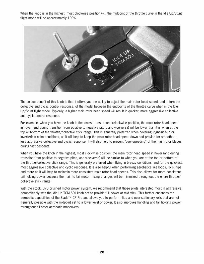
When.the.knob.is.in.the.middle.position,.pointing.directly.toward.the.back.of.the.transmitter,.the.midpoint.of.the.throttle.curve.in.the.Idle.Up/Stunt.flight.mode.will.be.approximately.75% .
�8
When.the.knob.is.in.the.highest,.most.clockwise.position.(+),.the.midpoint.of.the.throttle.curve.in.the.Idle.Up/Stunt.flight.mode.will.be.approximately.100% .
The.unique.benefit.of.this.knob.is.that.it.offers.you.the.ability.to.adjust.the.main.rotor.head.speed,.and.in.turn.the.collective.and.cyclic.control.response,.of.the.model.between.the.endpoints.of.the.throttle.curve.when.in.the.Idle.Up/Stunt.flight.mode ..Typically,.a.higher.main.rotor.head.speed.will.result.in.quicker,.more.aggressive.collective.and.cyclic.control.response .
For.example,.when.you.have.the.knob.in.the.lowest,.most.counterclockwise.position,.the.main.rotor.head.speed.in.hover.(and.during.transition.from.positive.to.negative.pitch,.and.vice-versa).will.be.lower.than.it.is.when.at.the.top.or.bottom.of.the.throttle/collective.stick.range ..This.is.generally.preferred.when.hovering.(right-side-up.or.inverted).in.calm.conditions,.as.it.will.help.to.keep.the.main.rotor.head.speed.down.and.provide.for.smoother,.less.aggressive.collective.and.cyclic.response ..It.will.also.help.to.prevent.“over-speeding”.of.the.main.rotor.blades.during.fast.descents .
When.you.have.the.knob.in.the.highest,.most.clockwise.position,.the.main.rotor.head.speed.in.hover.(and.during.transition.from.positive.to.negative.pitch,.and.vice-versa).will.be.similar.to.when.you.are.at.the.top.or.bottom.of.the.throttle/collective.stick.range ..This.is.generally.preferred.when.flying.in.breezy.conditions,.and.for.the.quickest,.most.aggressive.collective.and.cyclic.response ..It.is.also.helpful.when.performing.aerobatics.like.loops,.rolls,.flips.and.more.as.it.will.help.to.maintain.more.consistent.main.rotor.head.speeds ..This.also.allows.for.more.consistent.tail.holding.power.because.the.main.to.tail.motor.mixing.changes.will.be.minimized.throughout.the.entire.throttle/collective.stick.range .
With.the.stock,.370.brushed.motor.power.system,.we.recommend.that.those.pilots.interested.most.in.aggressive.aerobatics.fly.with.the.Idle.Up.TCM.ADJ.knob.set.to.provide.full.power.at.mid-stick ..This.further.enhances.the.aerobatic.capabilities.of.the.Blade™.CP.Pro.and.allows.you.to.perform.flips.and.near-stationary.rolls.that.are.not.generally.possible.with.the.midpoint.set.to.a.lower.level.of.power ..It.also.improves.handling.and.tail.holding.power.throughout.all.other.aerobatic.maneuvers .

�9
Note: The ESC in the �-in-1 used to control the main motor has been calibrated for a narrower range of throttle operation. For this reason, it will not be necessary to set the Idle Up TCM ADJ knob much beyond approximately 1/� travel in order to achieve 100% throttle at mid stick. This is not a problem and there is no adverse affect for having the knob adjusted to beyond approximately 1/� travel, though it is not necessary. The status LED indicator on the �-in-1 will turn solid red when full power has been achieved.
When.using.the.optional,.370.brushless.power.system.(as.seen.in.the.“Optional.Brushless.Main.Motor.Power.System.Installation.and.Setup”.section.found.on.pages.48–56),.we.recommend.adjusting.the.Idle.Up.TCM.ADJ.knob.to.provide.the.best.overall.combination.of.main.rotor.head.speed.and.collective/cyclic.response.depending.on.your.preferred.style.of.flying,.similar.to.as.noted.for.the.stock.bushed.370.power.system ..However,.please.note.that.while.it.is.possible.to.fly.with.the.midpoint.set.to.approximately.100%.throttle.when.using.the.optional.brushless.power.system,.care.must.be.taken.during.flight.to.prevent.over.speeding.of.the.main.rotor.blades,.especially.during.fast.descents .
Note: Some brushless ESCs may also be calibrated with a narrower range of throttle operation and could achieve 100% throttle before the Idle Up TCM ADJ knob reaches full travel. This is not a problem and should have no adverse affect on flight performance.
Please.see.the.“Programmed.Throttle.and.Pitch.Curves.for.the.Idle.Up/Stunt.Flight.Mode”.section.found.on.pages.31–32.for.more.information.regarding.adjustment.of.the.Idle.Up.TCM.ADJ.knob .
�0
Pitch Curve Adjustments
The.pitch.curves.have.already.been.factory.set.in.the.transmitter.for.both.Normal.and.Idle.Up/Stunt.flight.modes ..These.curves.have.been.tested.and.optimized.for.the.best.overall.performance.in.either.flight.mode ..
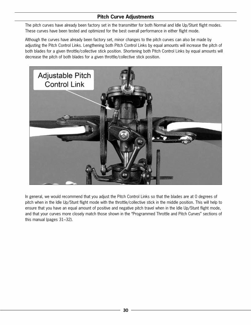
Although.the.curves.have.already.been.factory.set,.minor.changes.to.the.pitch.curves.can.also.be.made.by.adjusting.the.Pitch.Control.Links ..Lengthening.both.Pitch.Control.Links.by.equal.amounts.will.increase.the.pitch.of.both.blades.for.a.given.throttle/collective.stick.position ..Shortening.both.Pitch.Control.Links.by.equal.amounts.will.decrease.the.pitch.of.both.blades.for.a.given.throttle/collective.stick.position .
In.general,.we.would.recommend.that.you.adjust.the.Pitch.Control.Links.so.that.the.blades.are.at.0.degrees.of.pitch.when.in.the.Idle.Up/Stunt.flight.mode.with.the.throttle/collective.stick.in.the.middle.position ..This.will.help.to.ensure.that.you.have.an.equal.amount.of.positive.and.negative.pitch.travel.when.in.the.Idle.Up/Stunt.flight.mode,.and.that.your.curves.more.closely.match.those.shown.in.the.“Programmed.Throttle.and.Pitch.Curves”.sections.of.this.manual.(pages.31–32) .
�1
Programmed Throttle and Pitch Curves for the Normal Flight Mode
Right.from.the.box,.your.Blade™.CP.Pro.transmitter.has.been.programmed.for.the.following.throttle.and.pitch.curves.in.the.normal.flight.mode:
PITCH
STICK POSITION
Low Half High
+12°
0°
-12°
Programmed Throttle and Pitch Curves for the Idle Up/Stunt Flight Mode
Right.from.the.box,.your.Blade.CP.Pro.transmitter.has.been.programmed.for.the.following.throttle.and.pitch.curves.in.the.Idle.Up/Stunt.flight.mode:
With the Idle Up TCM ADJ knob in the lowest, most counterclockwise position.
PITCH
STICK POSITION
Low Half High
+12°
0°
-12°
��
With the Idle Up TCM ADJ knob in the middle position.
THROTTLE
STICK POSITION
Low Half High
100%
50%
0%
PITCH
STICK POSITION
Low Half High
+12°
0°
-12°
With the Idle Up TCM ADJ knob in the highest, most clockwise position.
THROTTLE
STICK POSITION
Low Half High
100%
50%
0%
PITCH
STICK POSITION
Low Half High
+12°
0°
-12°
��
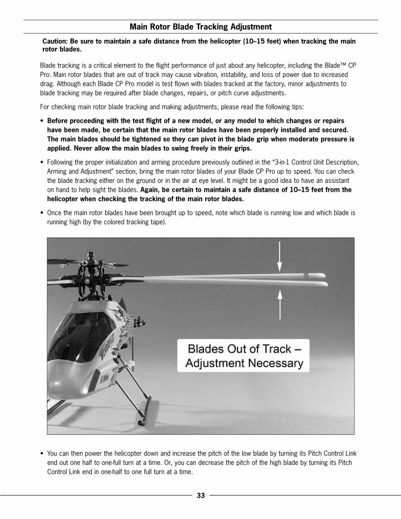
Main Rotor Blade Tracking Adjustment
Caution: Be sure to maintain a safe distance from the helicopter (10–1� feet) when tracking the main rotor blades.
Blade.tracking.is.a.critical.element.to.the.flight.performance.of.just.about.any.helicopter,.including.the.Blade™.CP.Pro ..Main.rotor.blades.that.are.out.of.track.may.cause.vibration,.instability,.and.loss.of.power.due.to.increased.drag ..Although.each.Blade.CP.Pro.model.is.test.flown.with.blades.tracked.at.the.factory,.minor.adjustments.to.blade.tracking.may.be.required.after.blade.changes,.repairs,.or.pitch.curve.adjustments .
For.checking.main.rotor.blade.tracking.and.making.adjustments,.please.read.the.following.tips:
• Before proceeding with the test flight of a new model, or any model to which changes or repairs have been made, be certain that the main rotor blades have been properly installed and secured. The main blades should be tightened so they can pivot in the blade grip when moderate pressure is applied. Never allow the main blades to swing freely in their grips.
•. Following.the.proper.initialization.and.arming.procedure.previously.outlined.in.the.“3-in-1.Control.Unit.Description,.Arming.and.Adjustment”.section,.bring.the.main.rotor.blades.of.your.Blade.CP.Pro.up.to.speed ..You.can.check.the.blade.tracking.either.on.the.ground.or.in.the.air.at.eye.level ..It.might.be.a.good.idea.to.have.an.assistant.on.hand.to.help.sight.the.blades ..Again, be certain to maintain a safe distance of 10–1� feet from the helicopter when checking the tracking of the main rotor blades.
•. Once.the.main.rotor.blades.have.been.brought.up.to.speed,.note.which.blade.is.running.low.and.which.blade.is.running.high.(by.the.colored.tracking.tape) .
•. You.can.then.power.the.helicopter.down.and.increase.the.pitch.of.the.low.blade.by.turning.its.Pitch.Control.Link.end.out.one.half.to.one-full.turn.at.a.time ..Or,.you.can.decrease.the.pitch.of.the.high.blade.by.turning.its.Pitch.Control.Link.end.in.one-half.to.one.full.turn.at.a.time .
��
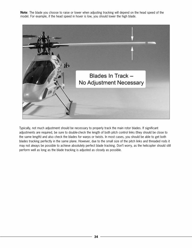
Note:.The.blade.you.choose.to.raise.or.lower.when.adjusting.tracking.will.depend.on.the.head.speed.of.the.model ..For.example,.if.the.head.speed.in.hover.is.low,.you.should.lower.the.high.blade .
Typically,.not.much.adjustment.should.be.necessary.to.properly.track.the.main.rotor.blades ..If.significant.adjustments.are.required,.be.sure.to.double-check.the.length.of.both.pitch.control.links.(they.should.be.close.to.the.same.length).and.also.check.the.blades.for.warps.or.twists ..In.most.cases,.you.should.be.able.to.get.both.blades.tracking.perfectly.in.the.same.plane ..However,.due.to.the.small.size.of.the.pitch.links.and.threaded.rods.it.may.not.always.be.possible.to.achieve.absolutely.perfect.blade.tracking ..Don’t.worry,.as.the.helicopter.should.still.perform.well.as.long.as.the.blade.tracking.is.adjusted.as.closely.as.possible .
��
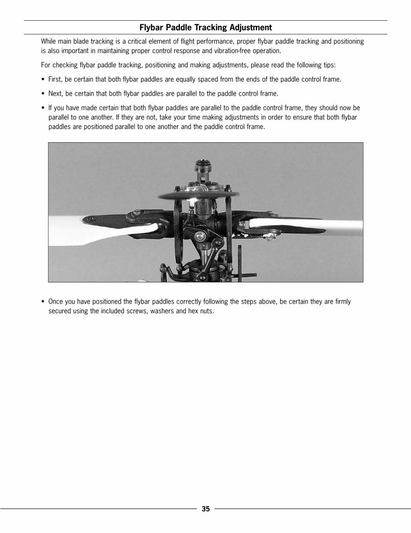
Flybar Paddle Tracking Adjustment
While.main.blade.tracking.is.a.critical.element.of.flight.performance,.proper.flybar.paddle.tracking.and.positioning.is.also.important.in.maintaining.proper.control.response.and.vibration-free.operation .
For.checking.flybar.paddle.tracking,.positioning.and.making.adjustments,.please.read.the.following.tips:
•. First,.be.certain.that.both.flybar.paddles.are.equally.spaced.from.the.ends.of.the.paddle.control.frame .
•. Next,.be.certain.that.both.flybar.paddles.are.parallel.to.the.paddle.control.frame .
•. If.you.have.made.certain.that.both.flybar.paddles.are.parallel.to.the.paddle.control.frame,.they.should.now.be.parallel.to.one.another ..If.they.are.not,.take.your.time.making.adjustments.in.order.to.ensure.that.both.flybar.paddles.are.positioned.parallel.to.one.another.and.the.paddle.control.frame .
•. Once.you.have.positioned.the.flybar.paddles.correctly.following.the.steps.above,.be.certain.they.are.firmly.secured.using.the.included.screws,.washers.and.hex.nuts .
��
Flybar Weights, Head Dampening Shims and Fine-Tuning Cyclic Response
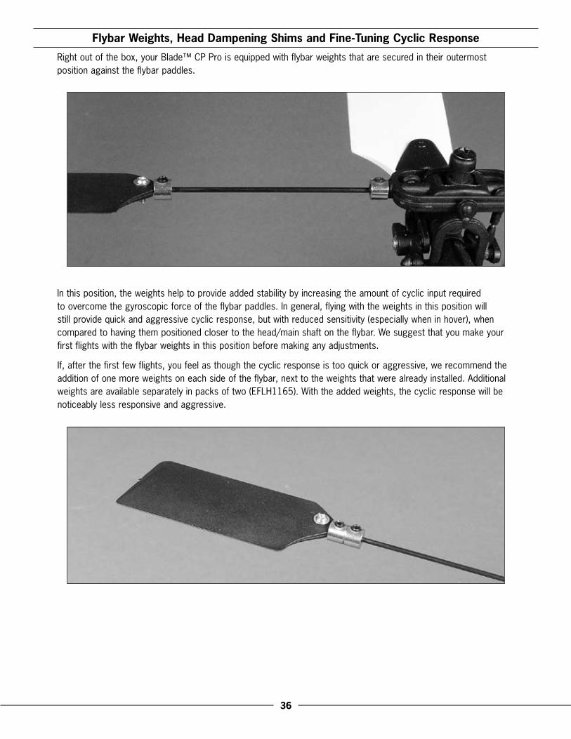
Right.out.of.the.box,.your.Blade™.CP.Pro.is.equipped.with.flybar.weights.that.are.secured.in.their.outermost.position.against.the.flybar.paddles .
In.this.position,.the.weights.help.to.provide.added.stability.by.increasing.the.amount.of.cyclic.input.required.to.overcome.the.gyroscopic.force.of.the.flybar.paddles ..In.general,.flying.with.the.weights.in.this.position.will.still.provide.quick.and.aggressive.cyclic.response,.but.with.reduced.sensitivity.(especially.when.in.hover),.when.compared.to.having.them.positioned.closer.to.the.head/main.shaft.on.the.flybar ..We.suggest.that.you.make.your.first.flights.with.the.flybar.weights.in.this.position.before.making.any.adjustments .
If,.after.the.first.few.flights,.you.feel.as.though.the.cyclic.response.is.too.quick.or.aggressive,.we.recommend.the.addition.of.one.more.weights.on.each.side.of.the.flybar,.next.to.the.weights.that.were.already.installed ..Additional.weights.are.available.separately.in.packs.of.two.(EFLH1165) ..With.the.added.weights,.the.cyclic.response.will.be.noticeably.less.responsive.and.aggressive .
��
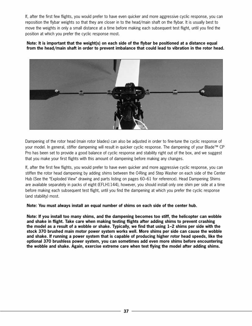
If,.after.the.first.few.flights,.you.would.prefer.to.have.even.quicker.and.more.aggressive.cyclic.response,.you.can.reposition.the.flybar.weights.so.that.they.are.closer.in.to.the.head/main.shaft.on.the.flybar ..It.is.usually.best.to.move.the.weights.in.only.a.small.distance.at.a.time.before.making.each.subsequent.test.flight,.until.you.find.the.position.at.which.you.prefer.the.cyclic.response.most .
Note: It is important that the weight(s) on each side of the flybar be positioned at a distance equal from the head/main shaft in order to prevent imbalance that could lead to vibration in the rotor head.
Dampening.of.the.rotor.head.(main.rotor.blades).can.also.be.adjusted.in.order.to.fine-tune.the.cyclic.response.of.your.model ..In.general,.stiffer.dampening.will.result.in.quicker.cyclic.response ..The.dampening.of.your.Blade™.CP.Pro.has.been.set.to.provide.a.good.balance.of.cyclic.response.and.stability.right.out.of.the.box,.and.we.suggest.that.you.make.your.first.flights.with.this.amount.of.dampening.before.making.any.changes .
If,.after.the.first.few.flights,.you.would.prefer.to.have.even.quicker.and.more.aggressive.cyclic.response,.you.can.stiffen.the.rotor.head.dampening.by.adding.shims.between.the.O-Ring.and.Step.Washer.on.each.side.of.the.Center.Hub.(See.the.“Exploded.View”.drawing.and.parts.listing.on.pages.60–61.for.reference) ..Head.Dampening.Shims.are.available.separately.in.packs.of.eight.(EFLH1144),.however,.you.should.install.only.one.shim.per.side.at.a.time.before.making.each.subsequent.test.flight,.until.you.find.the.dampening.at.which.you.prefer.the.cyclic.response.(and.stability).most .
Note: You must always install an equal number of shims on each side of the center hub.
Note: If you install too many shims, and the dampening becomes too stiff, the helicopter can wobble and shake in flight. Take care when making testing flights after adding shims to prevent crashing the model as a result of a wobble or shake. Typically, we find that using 1–� shims per side with the stock ��0 brushed main motor power system works well. More shims per side can cause the wobble and shake. If running a power system that is capable of producing higher rotor head speeds, like the optional ��0 brushless power system, you can sometimes add even more shims before encountering the wobble and shake. Again, exercise extreme care when test flying the model after adding shims.
�8
Channel � Knob Description and Function
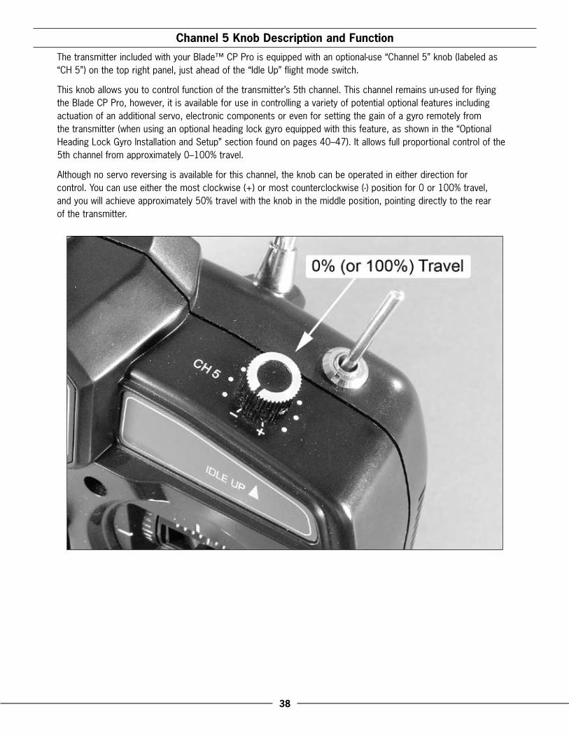
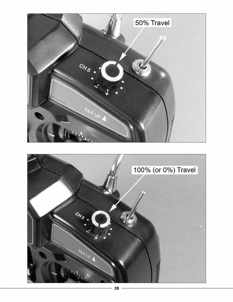
The.transmitter.included.with.your.Blade™.CP.Pro.is.equipped.with.an.optional-use.“Channel.5”.knob.(labeled.as.“CH.5”).on.the.top.right.panel,.just.ahead.of.the.“Idle.Up”.flight.mode.switch .
This.knob.allows.you.to.control.function.of.the.transmitter’s.5th.channel ..This.channel.remains.un-used.for.flying.the.Blade.CP.Pro,.however,.it.is.available.for.use.in.controlling.a.variety.of.potential.optional.features.including.actuation.of.an.additional.servo,.electronic.components.or.even.for.setting.the.gain.of.a.gyro.remotely.from.the.transmitter.(when.using.an.optional.heading.lock.gyro.equipped.with.this.feature,.as.shown.in.the.“Optional.Heading.Lock.Gyro.Installation.and.Setup”.section.found.on.pages.40–47) ..It.allows.full.proportional.control.of.the.5th.channel.from.approximately.0–100%.travel .
Although.no.servo.reversing.is.available.for.this.channel,.the.knob.can.be.operated.in.either.direction.for..control ..You.can.use.either.the.most.clockwise.(+).or.most.counterclockwise.(-).position.for.0.or.100%.travel,..and.you.will.achieve.approximately.50%.travel.with.the.knob.in.the.middle.position,.pointing.directly.to.the.rear..of.the.transmitter .
�9
�0
Optional Heading Lock Gyro Installation and Setup
A.unique.feature.of.the.Blade™.CP.Pro.is.that.it.allows.you.to.install.an.optional.“Heading.Lock”.type.gyro.to.further.enhance.the.holding.performance.and.response.of.the.tail,.without.the.need.for.difficult.modifications.or.an.alternative.radio.system ..While.the.stock.“Standard.Rate”.type.gyro.contained.in.the.3-in-1.control.unit.performs.well.for.many.types.of.flying,.a.heading.lock.gyro.offers.superior.tail.holding.power.that.helps.to.maintain.heading.throughout.even.the.most.aggressive.aerobatic.maneuvers .
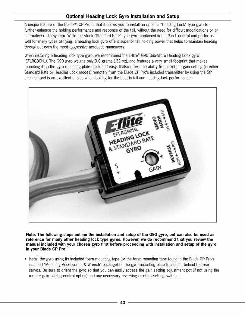
When.installing.a.heading.lock.type.gyro,.we.recommend.the.E-flite®.G90.Sub-Micro.Heading.Lock.gyro.(EFLRG90HL) ..The.G90.gyro.weighs.only.9 .0.grams.( .32.oz),.and.features.a.very.small.footprint.that.makes.mounting.it.on.the.gyro.mounting.plate.quick.and.easy ..It.also.offers.the.ability.to.control.the.gain.setting.(in.either.Standard.Rate.or.Heading.Lock.modes).remotely.from.the.Blade.CP.Pro’s.included.transmitter.by.using.the.5th.channel,.and.is.an.excellent.choice.when.looking.for.the.best.in.tail.and.heading.lock.performance .
Note: The following steps outline the installation and setup of the G90 gyro, but can also be used as reference for many other heading lock type gyros. However, we do recommend that you review the manual included with your chosen gyro first before proceeding with installation and setup of the gyro in your Blade CP Pro.
•. Install.the.gyro.using.its.included.foam.mounting.tape.(or.the.foam.mounting.tape.found.in.the.Blade.CP.Pro’s.included.“Mounting.Accessories.&.Wrench”.package).on.the.gyro.mounting.plate.found.just.behind.the.rear.servos ..Be.sure.to.orient.the.gyro.so.that.you.can.easily.access.the.gain.setting.adjustment.pot.(if.not.using.the.remote.gain.setting.control.option).and.any.necessary.reversing.or.other.setting.switches .
�1
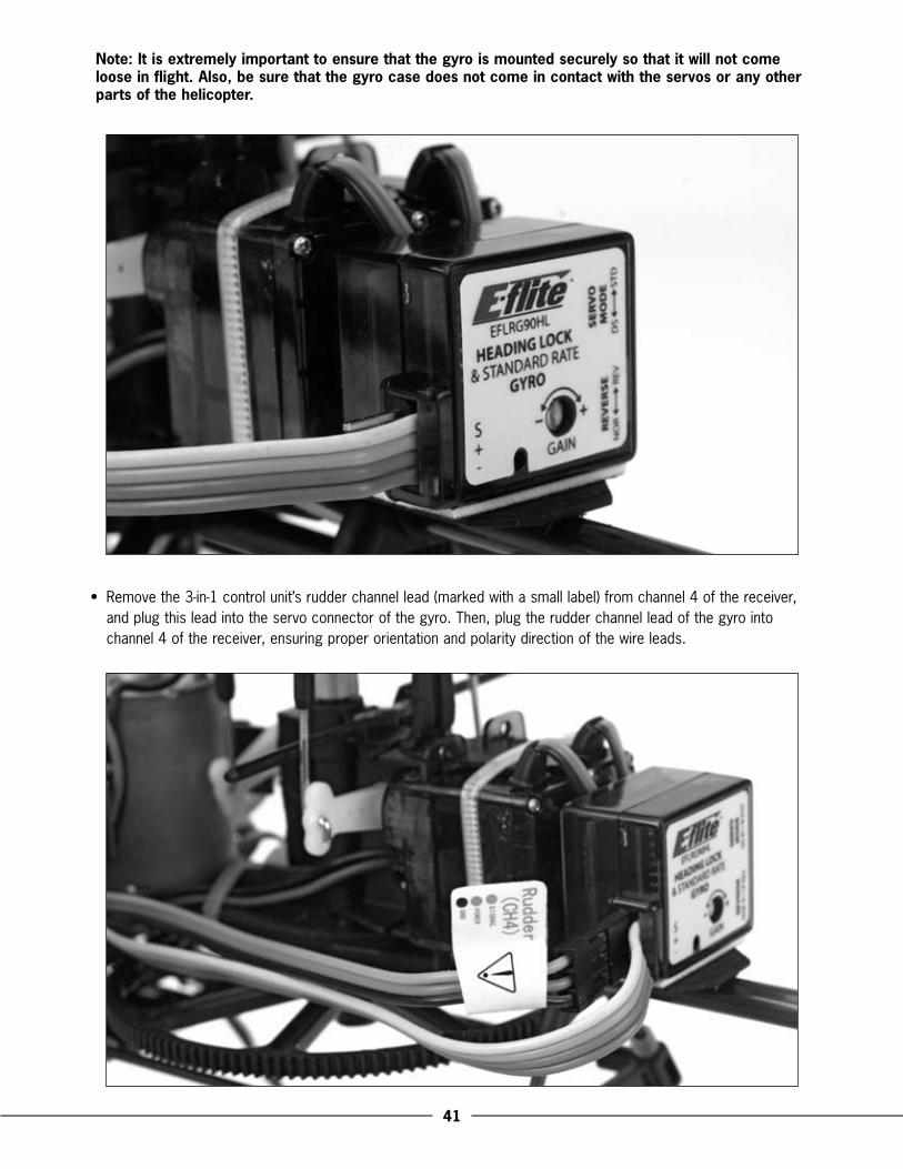
Note: It is extremely important to ensure that the gyro is mounted securely so that it will not come loose in flight. Also, be sure that the gyro case does not come in contact with the servos or any other parts of the helicopter.
•. Remove.the.3-in-1.control.unit’s.rudder.channel.lead.(marked.with.a.small.label).from.channel.4.of.the.receiver,.and.plug.this.lead.into.the.servo.connector.of.the.gyro ..Then,.plug.the.rudder.channel.lead.of.the.gyro.into.channel.4.of.the.receiver,.ensuring.proper.orientation.and.polarity.direction.of.the.wire.leads .
��
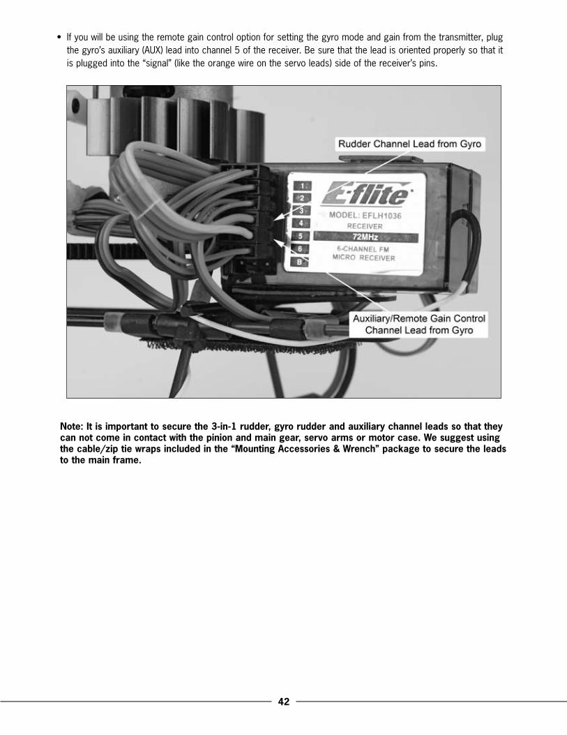
•. If.you.will.be.using.the.remote.gain.control.option.for.setting.the.gyro.mode.and.gain.from.the.transmitter,.plug.the.gyro’s.auxiliary.(AUX).lead.into.channel.5.of.the.receiver ..Be.sure.that.the.lead.is.oriented.properly.so.that.it.is.plugged.into.the.“signal”.(like.the.orange.wire.on.the.servo.leads).side.of.the.receiver’s.pins .
Note: It is important to secure the �-in-1 rudder, gyro rudder and auxiliary channel leads so that they can not come in contact with the pinion and main gear, servo arms or motor case. We suggest using the cable/zip tie wraps included in the “Mounting Accessories & Wrench” package to secure the leads to the main frame.
��
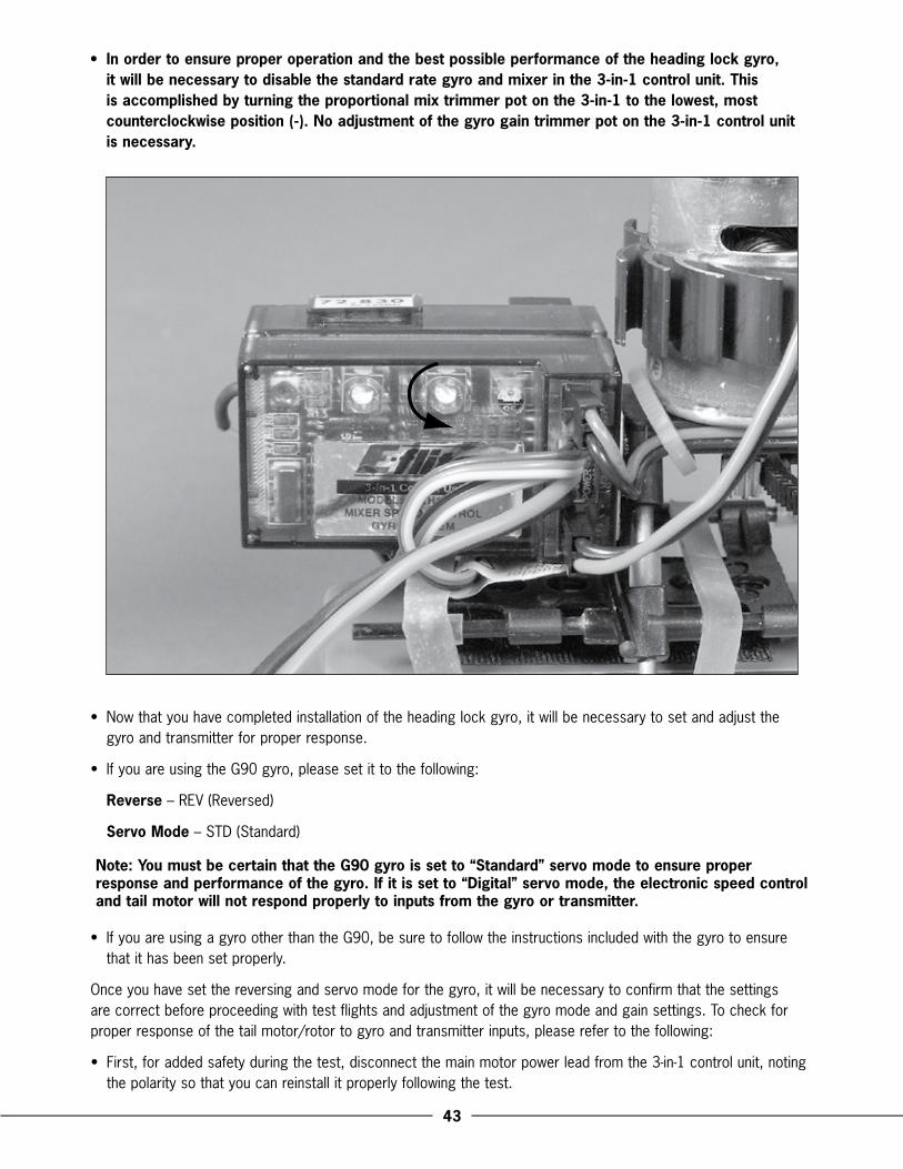
• In order to ensure proper operation and the best possible performance of the heading lock gyro, it will be necessary to disable the standard rate gyro and mixer in the �-in-1 control unit. This is accomplished by turning the proportional mix trimmer pot on the �-in-1 to the lowest, most counterclockwise position (-). No adjustment of the gyro gain trimmer pot on the �-in-1 control unit is necessary.
•. Now.that.you.have.completed.installation.of.the.heading.lock.gyro,.it.will.be.necessary.to.set.and.adjust.the.gyro.and.transmitter.for.proper.response .
•. If.you.are.using.the.G90.gyro,.please.set.it.to.the.following:
Reverse.–.REV.(Reversed)
Servo Mode.–.STD.(Standard)
Note: You must be certain that the G90 gyro is set to “Standard” servo mode to ensure proper response and performance of the gyro. If it is set to “Digital” servo mode, the electronic speed control and tail motor will not respond properly to inputs from the gyro or transmitter.
•. If.you.are.using.a.gyro.other.than.the.G90,.be.sure.to.follow.the.instructions.included.with.the.gyro.to.ensure.that.it.has.been.set.properly .
Once.you.have.set.the.reversing.and.servo.mode.for.the.gyro,.it.will.be.necessary.to.confirm.that.the.settings.are.correct.before.proceeding.with.test.flights.and.adjustment.of.the.gyro.mode.and.gain.settings ..To.check.for.proper.response.of.the.tail.motor/rotor.to.gyro.and.transmitter.inputs,.please.refer.to.the.following:
•. First,.for.added.safety.during.the.test,.disconnect.the.main.motor.power.lead.from.the.3-in-1.control.unit,.noting.the.polarity.so.that.you.can.reinstall.it.properly.following.the.test .

��
•. Next,.power.on.the.transmitter,.then.the.plug.the.battery.pack.into.the.battery.lead.of.the.3-in-1.control.unit ..Allow.time.for.the.3-in-1.control.unit.to.initialize.properly ..Also,.be.sure.to.allow.the.gyro.to.initialize.properly,.as.outlined.in.its.manual ..If.you.are.using.the.G90.gyro,.the.blue.status.LED.should.illuminate.solidly.just.before.the.status.LED.of.the.3-in-1.unit.becomes.solid.green ..This.will.indicate.that.the.gyro.and.3-in-1.control.unit.are.ready.for.the.test .
•. After.securing.the.helicopter.and.ensuring.that.all.objects.are.free.and.clear.of.the.tail.rotor.blades,.and.also.reconfirming.that.the.main.motor.power.lead.has.been.disconnected.from.the.3-in-1.control.unit,.advance.the.throttle/collective.stick.on.the.transmitter.to.approximately.1/3–1/2.travel ..Use.caution,.as.the.tail.motor.may.begin.to.spin.the.tail.rotor.blade .
•. Now.it.is.best.to.check.that.the.tail.motor/rotor.is.responding.properly.to.transmitter.inputs ..When.inputting.a.slight.amount.of.right.rudder,.the.tail.rotor.rpms.should.increase.(to.push.the.nose.of.the.helicopter.to.the.right) ..When.inputting.a.slight.amount.of.left.rudder,.the.tail.rotor.rpms.should.decrease.or.stop.entirely ..If.the.tail.motor/rotor.is.not.responding.properly,.use.the.Servo.Reversing.switch.located.on.the.front.of.the.transmitter.to.reverse.the.direction.of.response .
•. Once.confirming.that.the.tail.motor/rotor.is.responding.properly.to.transmitter.inputs,.it.will.also.be.necessary.to.confirm.that.it.is.responding.properly.to.inputs.from.the.gyro ..After.again.securing.the.helicopter.and.ensuring.that.all.objects.are.free.and.clear.from.the.tail.motor,.and.that.the.throttle.is.set.to.approximately.1/3–1/2.power,.quickly.twist.the.nose.of.the.helicopter.to.the.left ..If.the.tail.motor/rotor.is.responding.properly.to.inputs.from.the.gyro,.the.rpms.will.increase,.to.counteract.the.nose.twisting.to.the.left,.in.order.to.bring.the.nose.back.to.the.right ..When.quickly.twisting.the.nose.of.the.helicopter.to.right,.the.rpms.should.decrease.or.stop.entirely ..If.the.tail.motor/rotor.is.not.responding.properly,.use.the.Reverse.switch.located.on.the.gyro.to.reverse.the.direction.of.response .
•. After.confirming.that.the.tail.motor/rotor.is.responding.properly.to.inputs.from.the.gyro.and.transmitter,.disconnect.the.battery.from.the.3-in-1.control.unit,.power.down.the.transmitter.and.re-install.the.main.motor.power.lead.into.the.3-in-1.noting.proper.polarity.for.correct.operation .
��
Now.that.you.have.confirmed.proper.response.of.the.tail.motor/rotor.to.gyro.and.transmitter.inputs,.it.is.time.to.proceed.with.initial.adjustments.of.the.gyro.mode.and.gain.setting,.and.to.conduct.test.flights .
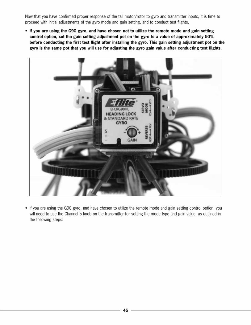
•. If you are using the G90 gyro, and have chosen not to utilize the remote mode and gain setting control option, set the gain setting adjustment pot on the gyro to a value of approximately �0% before conducting the first test flight after installing the gyro. This gain setting adjustment pot on the gyro is the same pot that you will use for adjusting the gyro gain value after conducting test flights.
•. If.you.are.using.the.G90.gyro,.and.have.chosen.to.utilize.the.remote.mode.and.gain.setting.control.option,.you.will.need.to.use.the.Channel.5.knob.on.the.transmitter.for.setting.the.mode.type.and.gain.value,.as.outlined.in.the.following.steps:
��
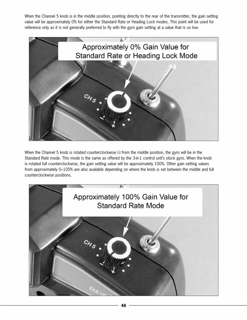
When.the.Channel.5.knob.is.in.the.middle.position,.pointing.directly.to.the.rear.of.the.transmitter,.the.gain.setting.value.will.be.approximately.0%.for.either.the.Standard.Rate.or.Heading.Lock.modes ..This.point.will.be.used.for.reference.only.as.it.is.not.generally.preferred.to.fly.with.the.gyro.gain.setting.at.a.value.that.is.so.low .
When.the.Channel.5.knob.is.rotated.counterclockwise.(-).from.the.middle.position,.the.gyro.will.be.in.the..Standard.Rate.mode ..This.mode.is.the.same.as.offered.by.the.3-in-1.control.unit’s.stock.gyro ..When.the.knob..is.rotated.full.counterclockwise,.the.gain.setting.value.will.be.approximately.100% ..Other.gain.setting.values..from.approximately.0–100%.are.also.available.depending.on.where.the.knob.is.set.between.the.middle.and.full.counterclockwise.positions .
��
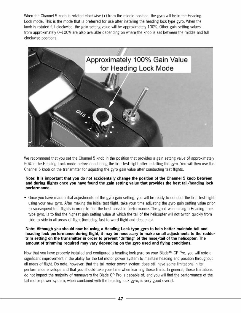
When.the.Channel.5.knob.is.rotated.clockwise.(+).from.the.middle.position,.the.gyro.will.be.in.the.Heading.Lock.mode ..This.is.the.mode.that.is.preferred.for.use.after.installing.the.heading.lock.type.gyro ..When.the.knob.is.rotated.full.clockwise,.the.gain.setting.value.will.be.approximately.100% ..Other.gain.setting.values.from.approximately.0–100%.are.also.available.depending.on.where.the.knob.is.set.between.the.middle.and.full.clockwise.positions .
We.recommend.that.you.set.the.Channel.5.knob.in.the.position.that.provides.a.gain.setting.value.of.approximately.50%.in.the.Heading.Lock.mode.before.conducting.the.first.test.flight.after.installing.the.gyro ..You.will.then.use.the.Channel.5.knob.on.the.transmitter.for.adjusting.the.gyro.gain.value.after.conducting.test.flights .
Note: It is important that you do not accidentally change the position of the Channel � knob between and during flights once you have found the gain setting value that provides the best tail/heading lock performance.
•. Once.you.have.made.initial.adjustments.of.the.gyro.gain.setting,.you.will.be.ready.to.conduct.the.first.test.flight.using.your.new.gyro ..After.making.the.initial.test.flight,.take.your.time.adjusting.the.gyro.gain.setting.value.prior.to.subsequent.test.flights.in.order.to.find.the.best.possible.performance ..The.goal,.when.using.a.Heading.Lock.type.gyro,.is.to.find.the.highest.gain.setting.value.at.which.the.tail.of.the.helicopter.will.not.twitch.quickly.from.side.to.side.in.all.areas.of.flight.(including.fast.forward.flight.and.descents) ..
Note: Although you should now be using a Heading Lock type gyro to help better maintain tail and heading lock performance during flight, it may be necessary to make small adjustments to the rudder trim setting on the transmitter in order to prevent “drifting” of the nose/tail of the helicopter. The amount of trimming required may vary depending on the gyro used and flying conditions.
Now.that.you.have.properly.installed.and.configured.a.heading.lock.gyro.on.your.Blade™.CP.Pro,.you.will.note.a.significant.improvement.in.the.ability.for.the.tail.motor.power.system.to.maintain.heading.and.position.throughout.all.areas.of.flight ..Do.note,.however,.that.the.tail.motor.power.system.does.still.have.some.limitations.in.its.performance.envelope.and.that.you.should.take.your.time.when.learning.these.limits ..In.general,.these.limitations.do.not.impact.the.majority.of.maneuvers.the.Blade.CP.Pro.is.capable.of,.and.you.will.find.the.performance.of.the.tail.motor.power.system,.when.combined.with.the.heading.lock.gyro,.is.very.good.overall .
�8
Optional Brushless Main Motor Power System Installation and Setup
The.Blade™.CP.Pro’s.separate.6-channel.FM.receiver.and.3-in-1.control.unit.allow.you.the.option.of.upgrading.to.a.brushless.main.motor.power.system,.without.the.need.for.difficult.modifications.or.a.new.radio.system ..An.optional.brushless.main.motor.power.system.can.provide.added.power.and/or.duration.when.compared.to.the.stock.brushed.main.motor.power.system,.and.is.an.excellent.choice.for.those.interested.in.maximizing.the.performance.and.aerobatic.potential.of.their.model .
Note: When installing a brushless main motor power system, we also highly recommend the installation of an optional heading lock type gyro to help maximize performance of the tail due to the added torque and performance the brushless main motor will provide.
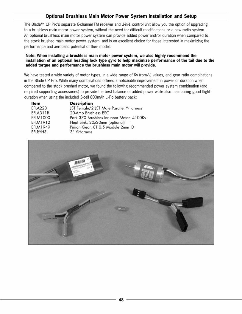
We.have.tested.a.wide.variety.of.motor.types,.in.a.wide.range.of.Kv.(rpm/v).values,.and.gear.ratio.combinations.in.the.Blade.CP.Pro ..While.many.combinations.offered.a.noticeable.improvement.in.power.or.duration.when.compared.to.the.stock.brushed.motor,.we.found.the.following.recommended.power.system.combination.(and.required.supporting.accessories).to.provide.the.best.balance.of.added.power.while.also.maintaining.good.flight.duration.when.using.the.included.3-cell.800mAh.Li-Po.battery.pack:
Item DescriptionEFLA228 JST Female/2 JST Male Parallel Y-HarnessEFLA311B 20-Amp Brushless ESCEFLM1000 Park 370 Brushless Inrunner Motor, 4100KvEFLM1912 Heat Sink, 20x20mm (optional)EFLM1949 Pinion Gear, 8T 0.5 Module 2mm IDEFLRYH3 3” Y-Harness
�9
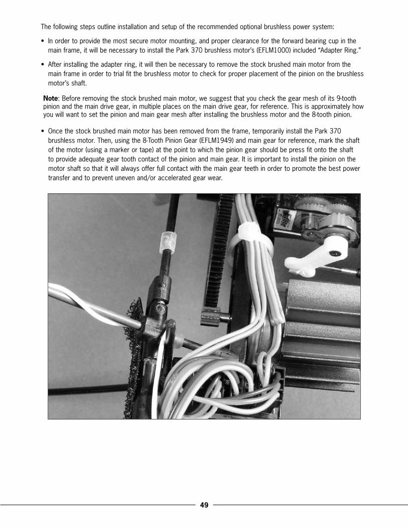
The.following.steps.outline.installation.and.setup.of.the.recommended.optional.brushless.power.system:
•. In.order.to.provide.the.most.secure.motor.mounting,.and.proper.clearance.for.the.forward.bearing.cup.in.the.main.frame,.it.will.be.necessary.to.install.the.Park.370.brushless.motor’s.(EFLM1000).included.“Adapter.Ring .”
•. After.installing.the.adapter.ring,.it.will.then.be.necessary.to.remove.the.stock.brushed.main.motor.from.the.main.frame.in.order.to.trial.fit.the.brushless.motor.to.check.for.proper.placement.of.the.pinion.on.the.brushless.motor’s.shaft .
Note:.Before.removing.the.stock.brushed.main.motor,.we.suggest.that.you.check.the.gear.mesh.of.its.9-tooth.pinion.and.the.main.drive.gear,.in.multiple.places.on.the.main.drive.gear,.for.reference ..This.is.approximately.how.you.will.want.to.set.the.pinion.and.main.gear.mesh.after.installing.the.brushless.motor.and.the.8-tooth.pinion .
•. Once.the.stock.brushed.main.motor.has.been.removed.from.the.frame,.temporarily.install.the.Park.370.brushless.motor ..Then,.using.the.8-Tooth.Pinion.Gear.(EFLM1949).and.main.gear.for.reference,.mark.the.shaft.of.the.motor.(using.a.marker.or.tape).at.the.point.to.which.the.pinion.gear.should.be.press.fit.onto.the.shaft.to.provide.adequate.gear.tooth.contact.of.the.pinion.and.main.gear ..It.is.important.to.install.the.pinion.on.the.motor.shaft.so.that.it.will.always.offer.full.contact.with.the.main.gear.teeth.in.order.to.promote.the.best.power.transfer.and.to.prevent.uneven.and/or.accelerated.gear.wear .
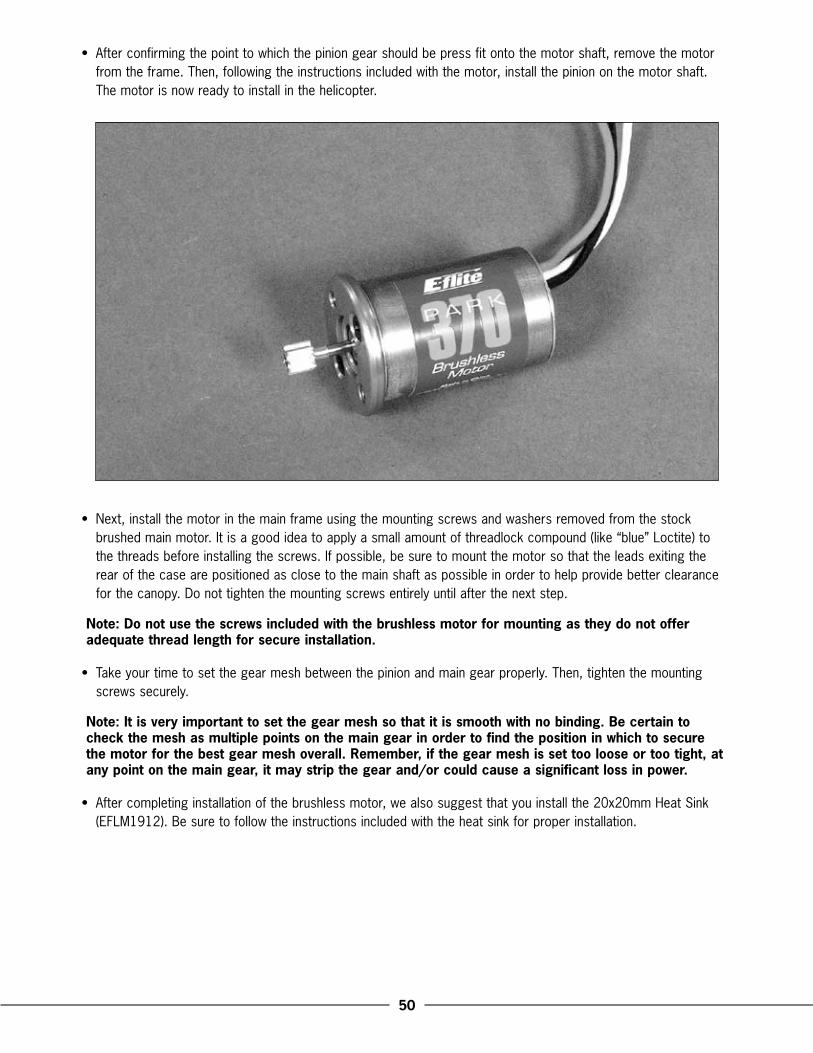
�0
•. After.confirming.the.point.to.which.the.pinion.gear.should.be.press.fit.onto.the.motor.shaft,.remove.the.motor.from.the.frame ..Then,.following.the.instructions.included.with.the.motor,.install.the.pinion.on.the.motor.shaft ..The.motor.is.now.ready.to.install.in.the.helicopter .
•. Next,.install.the.motor.in.the.main.frame.using.the.mounting.screws.and.washers.removed.from.the.stock.brushed.main.motor ..It.is.a.good.idea.to.apply.a.small.amount.of.threadlock.compound.(like.“blue”.Loctite).to.the.threads.before.installing.the.screws ..If.possible,.be.sure.to.mount.the.motor.so.that.the.leads.exiting.the.rear.of.the.case.are.positioned.as.close.to.the.main.shaft.as.possible.in.order.to.help.provide.better.clearance.for.the.canopy ..Do.not.tighten.the.mounting.screws.entirely.until.after.the.next.step ..
Note: Do not use the screws included with the brushless motor for mounting as they do not offer adequate thread length for secure installation.
•. Take.your.time.to.set.the.gear.mesh.between.the.pinion.and.main.gear.properly ..Then,.tighten.the.mounting.screws.securely .
Note: It is very important to set the gear mesh so that it is smooth with no binding. Be certain to check the mesh as multiple points on the main gear in order to find the position in which to secure the motor for the best gear mesh overall. Remember, if the gear mesh is set too loose or too tight, at any point on the main gear, it may strip the gear and/or could cause a significant loss in power.
•. After.completing.installation.of.the.brushless.motor,.we.also.suggest.that.you.install.the.20x20mm.Heat.Sink.(EFLM1912) ..Be.sure.to.follow.the.instructions.included.with.the.heat.sink.for.proper.installation .
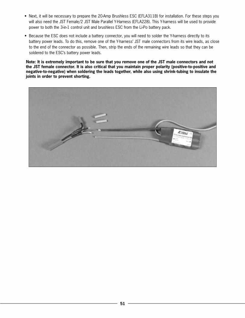
�1
•. Next,.it.will.be.necessary.to.prepare.the.20-Amp.Brushless.ESC.(EFLA311B).for.installation ..For.these.steps.you.will.also.need.the.JST.Female/2.JST.Male.Parallel.Y-Harness.(EFLA228) ..This.Y-harness.will.be.used.to.provide.power.to.both.the.3-in-1.control.unit.and.brushless.ESC.from.the.Li-Po.battery.pack .
•. Because.the.ESC.does.not.include.a.battery.connector,.you.will.need.to.solder.the.Y-harness.directly.to.its.battery.power.leads ..To.do.this,.remove.one.of.the.Y-harness’.JST.male.connectors.from.its.wire.leads,.as.close.to.the.end.of.the.connector.as.possible ..Then,.strip.the.ends.of.the.remaining.wire.leads.so.that.they.can.be.soldered.to.the.ESC’s.battery.power.leads ..
Note: It is extremely important to be sure that you remove one of the JST male connectors and not the JST female connector. It is also critical that you maintain proper polarity (positive-to-positive and negative-to-negative) when soldering the leads together, while also using shrink-tubing to insulate the joints in order to prevent shorting.
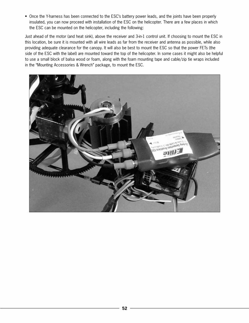
��
•. Once.the.Y-harness.has.been.connected.to.the.ESC’s.battery.power.leads,.and.the.joints.have.been.properly.insulated,.you.can.now.proceed.with.installation.of.the.ESC.on.the.helicopter ..There.are.a.few.places.in.which.the.ESC.can.be.mounted.on.the.helicopter,.including.the.following:
Just.ahead.of.the.motor.(and.heat.sink),.above.the.receiver.and.3-in-1.control.unit ..If.choosing.to.mount.the.ESC.in.this.location,.be.sure.it.is.mounted.with.all.wire.leads.as.far.from.the.receiver.and.antenna.as.possible,.while.also.providing.adequate.clearance.for.the.canopy ..It.will.also.be.best.to.mount.the.ESC.so.that.the.power.FETs.(the.side.of.the.ESC.with.the.label).are.mounted.toward.the.top.of.the.helicopter ..In.some.cases.it.might.also.be.helpful.to.use.a.small.block.of.balsa.wood.or.foam,.along.with.the.foam.mounting.tape.and.cable/zip.tie.wraps.included.in.the.“Mounting.Accessories.&.Wrench”.package,.to.mount.the.ESC .
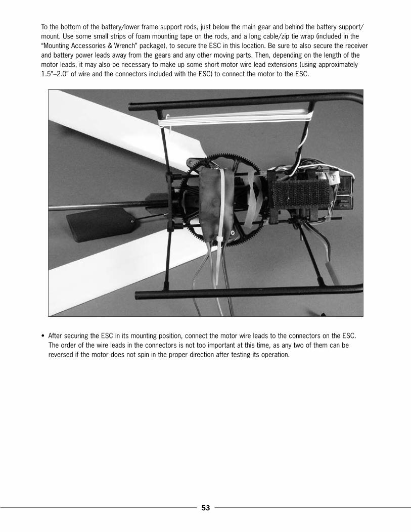
��
To.the.bottom.of.the.battery/lower.frame.support.rods,.just.below.the.main.gear.and.behind.the.battery.support/mount ..Use.some.small.strips.of.foam.mounting.tape.on.the.rods,.and.a.long.cable/zip.tie.wrap.(included.in.the.“Mounting.Accessories.&.Wrench”.package),.to.secure.the.ESC.in.this.location ..Be.sure.to.also.secure.the.receiver.and.battery.power.leads.away.from.the.gears.and.any.other.moving.parts ..Then,.depending.on.the.length.of.the.motor.leads,.it.may.also.be.necessary.to.make.up.some.short.motor.wire.lead.extensions.(using.approximately.1 .5”–2 .0”.of.wire.and.the.connectors.included.with.the.ESC).to.connect.the.motor.to.the.ESC .
•. After.securing.the.ESC.in.its.mounting.position,.connect.the.motor.wire.leads.to.the.connectors.on.the.ESC ..The.order.of.the.wire.leads.in.the.connectors.is.not.too.important.at.this.time,.as.any.two.of.them.can.be.reversed.if.the.motor.does.not.spin.in.the.proper.direction.after.testing.its.operation .
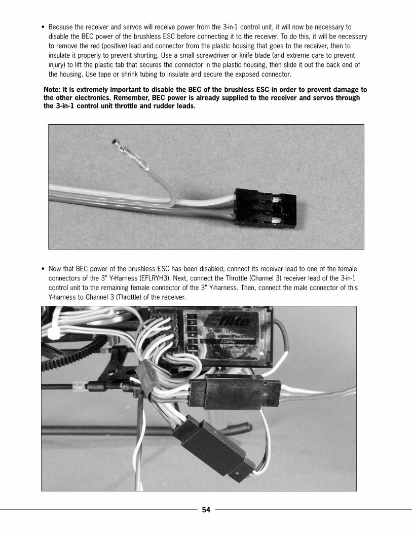
��
•. Because.the.receiver.and.servos.will.receive.power.from.the.3-in-1.control.unit,.it.will.now.be.necessary.to.disable.the.BEC.power.of.the.brushless.ESC.before.connecting.it.to.the.receiver ..To.do.this,.it.will.be.necessary.to.remove.the.red.(positive).lead.and.connector.from.the.plastic.housing.that.goes.to.the.receiver,.then.to.insulate.it.properly.to.prevent.shorting ..Use.a.small.screwdriver.or.knife.blade.(and.extreme.care.to.prevent.injury).to.lift.the.plastic.tab.that.secures.the.connector.in.the.plastic.housing,.then.slide.it.out.the.back.end.of.the.housing ..Use.tape.or.shrink.tubing.to.insulate.and.secure.the.exposed.connector .
Note: It is extremely important to disable the BEC of the brushless ESC in order to prevent damage to the other electronics. Remember, BEC power is already supplied to the receiver and servos through the �-in-1 control unit throttle and rudder leads.
•. Now.that.BEC.power.of.the.brushless.ESC.has.been.disabled,.connect.its.receiver.lead.to.one.of.the.female.connectors.of.the.3”.Y-Harness.(EFLRYH3) ..Next,.connect.the.Throttle.(Channel.3).receiver.lead.of.the.3-in-1.control.unit.to.the.remaining.female.connector.of.the.3”.Y-harness ..Then,.connect.the.male.connector.of.this..Y-harness.to.Channel.3.(Throttle).of.the.receiver .

��
•. To.complete.installation.and.wiring.hook-up.of.the.brushless.ESC,.connect.the.remaining.JST.male.connector.of.the.battery.power.lead.Y-harness.to.the.female.JST.connector.of.the.3-in-1.control.unit ..Be.sure.to.then.secure.the.battery.power.leads.of.the.brushless.ESC.and.3-in-1.so.that.they.cannot.come.into.contact.with.the.gears.or.any.other.moving.parts,.and.so.that.you.can.readily.access.the.remaining.JST.female.connector.for.connecting.the.battery.pack .
Now.that.you.have.completed.installation.of.the.optional.brushless.power.system,.it.will.be.necessary.to.check.that.the.ESC.is.set.properly.to.ensure.maximum.performance,.and.that.the.motor.is.operating.in.the.correct.direction ..Before.proceeding.with.these.checks,.however,.unplug.the.tail.motor.wires.from.the.3-in-1.control.unit.making.note.of.their.direction.and.polarity.for.proper.re-installation.after.the.checks.are.complete ..Also,.remove.the.main.rotor.blades.and.mounting.bolts/nuts.from.the.main.blade.grips.to.help.ensure.safety ..Then,.follow.these.steps.(if.using.the.E-flite®.20-Amp.ESC):
•. Turn.the.transmitter.on.first.and.advance.the.throttle.stick.to.full.power ..Then,.after.placing.your.hand.on.the.rotor.head.and.securing.the.helicopter.so.that.it.will.not.be.able.to.move.and.that.you.can.quickly.disconnect.the.battery.if.power.to.the.motor.is.applied,.plug.the.battery.into.the.battery.lead.Y-harness.connected.to.the.3-in-1.control.unit.and.brushless.ESC ..You.should.then.hear.the.beep.to.signal.power.up.of.the.brushless.ESC,.followed.by.an.additional.beep.to.indicate.that.the.ESC.has.entered.the.programming.mode .
Note: Exercise extreme caution and care when programming the brushless ESC with the motor pinion gear meshed properly to the main gear. Although the ESC is equipped with safe power-on software and should not apply power to the motor, you must still be very careful. If, at any time, power to the motor is applied and the rotor head begins to spin, unplug the battery immediately to prevent any damage to the model and electronics, or even personal injury.
•. Follow.the.instructions.included.with.the.ESC.to.set.the.programming.for.the.brake.and.voltage.cutoff.to.the.following:
Voltage Cutoff.–.Auto.Li-Po.ON
Note:.With.the.voltage.cutoff.programming.set.to.Auto.Li-Po.ON,.a.soft.cutoff.of.motor.power.(usually.noticeable.as.a.quick.“pulsing”.of.motor.power.under.load).will.occur.when.the.voltage.of.the.3-cell.Li-Po.battery.pack.reaches.9V.under.load ..This.is.generally.preferred.in.most.cases,.however,.you.can.disable.the.Auto.Li-Po.soft.cutoff.entirely.by.setting.the.voltage.cutoff.programming.to.Auto.Ni-Cd/Ni-MH.ON ..In.this.mode,.soft.cutoff.of.motor.power.will.not.occur.until.approximately.5 .0V.under.load,.even.when.using.a.3-cell.Li-Po.battery.pack.for.power ..However,.this.means.you.must.exercise.extreme.care.to.prevent.over-discharging.the.Li-Po.battery.pack.during.flight .
Brake.–.OFF
Note: It is extremely important that the motor brake programming of the ESC is disabled in order to prevent damage to the main gear and other components.
Once.you.have.confirmed.that.the.ESC’s.programming.for.the.voltage.cutoff.and.braking.is.correct,..disconnect.the.battery.from.the.power.leads ..You.will.now.need.to.also.confirm.that.the.motor.is.operating..in.the.correct.direction .
•. Turn.the.transmitter.on.first.and.lower.the.throttle.stick.and.trim.completely ..Then,.plug.the.battery.into.the.battery.lead.Y-harness.connected.to.the.3-in-1.control.unit.and.brushless.ESC ..You.should.then.almost.immediately.hear.beeps.from.the.brushless.ESC.to.indicate.that.it.is.armed.and.ready.for.use .
Note: The brushless ESC will almost always arm before the �-in-1 control unit. This is extremely important to remember because the main motor will then run if the throttle stick is advanced, even if the �-in-1 has yet to arm. Be certain to exercise extreme caution when waiting for the �-in-1 control unit to arm, especially if the brushless ESC has already been armed.
��
•. Once.the.brushless.ESC.has.armed.properly,.you.have.placed.the.helicopter.in.a.safe.place.free.of.obstructions,.and.are.clear.of.the.flybar.paddles,.you.can.safely.power.up.the.model.to.check.operating.direction.of.the.motor .
•. Advance.the.throttle.stick.slowly,.just.until.the.flybar.paddles.begin.to.spin,.and.note.the.direction ..The..flybar.paddles.should.spin.clockwise.when.viewed.from.the.top ..If.they.are.operating.in.the.wrong.direction,.unplug.the.battery,.then.simply.reverse.the.order.of.any.two.of.the.brushless.motor.leads.where.they.connect.to.the.ESC ..Then,.repeat.the.test.to.confirm.that.the.flybar.paddles.(and.motor).are.operating.in.the.correct.direction.before.proceeding .
After.confirming.that.the.brushless.main.motor.is.operating.in.the.correct.direction,.and.that.you.have.disconnected.the.battery,.reconnect.the.tail.motor.wires.to.the.3-in-1.control.unit ..Take.care.to.keep.the.proper.polarity.and.location.of.the.wires.as.they.were.before.the.check,.noting.that.tail.motor.plug.should.be.installed.into.the.upper.output.slot.of.the.3-in-1.control.unit.with.the.positive.lead.to.the.top ..Then,.re-attach.the.main.rotor.blades.to.the.blade.grips.using.the.mounting.bolts/nuts .
Your.Blade™.CP.Pro.is.now.ready.to.fly.with.the.optional.brushless.main.motor.power.system ..Be.sure.to..take.extra.care.when.making.the.first.test.flights.with.the.new.power.system.as.it.will.offer.a.significant.improvement.in.performance.over.the.stock.brushed.main.motor.power.system ..Also,.be.sure.to.take.your..time.to.re-adjust.the.Tail.Rotor.Proportional.Mix.and.Gyro.Gain.Trimmer.Pots.(or.the.gain.setting.value.if.using.a.heading.lock.type.gyro),.as.well.as.the.Idle.Up.TCM.ADJ.knob,.to.find.the.best.possible.performance.with.the.brushless.power.system .
Optional Spektrum Radio System Installation and Setup
The.Blade.CP.Pro’s.included.FM.72MHz.radio.system.performs.well.in.a.variety.of.flight.conditions.and.allows.you.to.perform.even.the.most.aggressive.aerobatic.maneuvers.right.out.of.the.box ..Crystal.sets.are.also.available.for.using.this.system.on.6.different.channels.in.the.72MHz.band.(17,.19,.21,.50,.52.and.54) ..But.because.this.system.utilizes.a.receiver.that.is.separate.from.the.other.on-board.electronics,.it.can.also.be.readily.changed.to.an.alternative.radio.system.that.may.offer.more.advanced.programming.features,.such.as.dual.rates,.exponential,.mixing.and.more,.to.allow.you.to.further.fine-tune.the.performance.of.your.model ..
When.choosing.an.alternative.radio.system.for.controlling.your.model,.we.recommend.a.Spektrum.DSM.(Digital.Spectrum.Modulation).equipped.DX6.Park.Flyer.System.(SPM2460) ..The.DX6.transmitter.offers.6-channels,.programmable.dual.rates,.exponential,.CCPM,.revolution.mixing,.10-model.memory.and.more ..The.included.AR6000.6-channel.receiver.weighs.only.7 .0.grams.( .25.oz).and.features.Spektrum’s.patent-pending.DuaLink™.system.that.employs.two.of.the.2 .4GHz.band’s.80.channels.in.a.unique.protocol.that.delivers.a.redundant,.ultra-reliable.RF.link ..Best.of.all,.because.the.DX6.system.operates.on.2 .4GHz,.glitching.and.range.impairment.from.motor,.ESC,.servo.and.mechanical.RF.“noise”.will.be.a.thing.of.the.past .
For.more.information.on.Spektrum,.the.DX6.system.and.installation.and.setup.of.this.system.in.your.Blade.CP.Pro,.please.visit.www .horizonhobby .com .

��
�00� Official AMA National Model Aircraft Safety Code
GENERAL
1)..I.will.not.fly.my.model.aircraft.in.sanctioned.events,.air.shows.or.model.flying.demonstrations.until.it.has.been.proven.to.be.airworthy.by.having.been.previously,.successfully.flight.tested .
2)..I.will.not.fly.my.model.higher.than.approximately.400.feet.within.3.miles.of.an.airport.without.notifying.the.airport.operator ..I.will.give.right-of-way.and.avoid.flying.in.the.proximity.of.full-scale.aircraft ..Where.necessary,.an.observer.shall.be.utilized.to.supervise.flying.to.avoid.having.models.fly.in.the.proximity.of.full-scale.aircraft .
3)..Where.established,.I.will.abide.by.the.safety.rules.for.the.flying.site.I.use,.and.I.will.not.willfully.or.deliberately.fly.my.models.in.a.careless,.reckless.and/or.dangerous.manner .
4).The.maximum.takeoff.weight.of.a.model.is.55.pounds,.except.models.flown.under.Experimental.Aircraft.rules .
5)..I.will.not.fly.my.model.unless.it.is.identified.with.my.name.and.address.or.AMA.number.on.or.in.the.model ..(This.does.not.apply.to.models.while.being.flown.indoors .)
6)..I.will.not.operate.models.with.metal-bladed.propellers.or.with.gaseous.boosts,.in.which.gases.other.than.air.enter.their.internal.combustion.engine(s);.nor.will.I.operate.models.with.extremely.hazardous.fuels.such.as.those.containing.tetranitromethane.or.hydrazine .
RADIO.CONTROL
1)..I.will.have.completed.a.successful.radio.equipment.ground.range.check.before.the.first.flight.of.a.new.or.repaired.model .
2)..I.will.not.fly.my.model.aircraft.in.the.presence.of.spectators.until.I.become.a.qualified.flier,.unless.assisted.by.an.experienced.helper .
3)..At.all.flying.sites.a.straight.or.curved.line(s).must.be.established.in.front.of.which.all.flying.takes.place.with.the.other.side.for.spectators ..Only.personnel.involved.with.flying.the.aircraft.are.allowed.at.or.in.front.of.the.flight.line ..Intentional.flying.behind.the.flight.line.is.prohibited .
4)..I.will.operate.my.model.using.only.radio.control.frequencies.currently.allowed.by.the.Federal.Communications.Commission ..(Only.properly.licensed.Amateurs.are.authorized.to.operate.equipment.on.Amateur.Band.frequencies .)
5)..Flying.sites.separated.by.three.miles.or.more.are.considered.safe.from.site-to.site.interference,.even.when.both.sites.use.the.same.frequencies ..Any.circumstances.under.three.miles.separation.require.a.frequency.management.arrangement,.which.may.be.either.an.allocation.of.specific.frequencies.for.each.site.or.testing.to.determine.that.freedom.from.interference.exists ..Allocation.plans.or.interference.test.reports.shall.be.signed.by.the.parties.involved.and.provided.to.AMA.Headquarters ..Documents.of.agreement.and.reports.may.exist.between.(1).two.or.more.AMA.Chartered.Clubs,.(2).AMA.clubs.and.individual.AMA.members.not.associated.with.AMA.Clubs,.or.(3).two.or.more.individual.AMA.members .
6)..For.Combat,.distance.between.combat.engagement.line.and.spectator.line.will.be.500.feet.per.cubic.inch.of.engine.displacement ..(Example:. .40.engine.=.200.feet .);.electric.motors.will.be.based.on.equivalent.combustion.engine.size ..Additional.safety.requirements.will.be.per.the.RC.Combat.section.of.the.current.Competition.Regulations .
7)..At.air.shows.or.model.flying.demonstrations,.a.single.straight.line.must.be.established,.one.side.of.which.is.for.flying,.with.the.other.side.for.spectators .
8)..With.the.exception.of.events.flown.under.AMA.Competition.rules,.after.launch,.except.for.pilots.or.helpers.being.used,.no.powered.model.may.be.flown.closer.than.25.feet.to.any.person .
9).Under.no.circumstances.may.a.pilot.or.other.person.touch.a.powered.model.in.flight .

�8
EFLH1300 ......Blade CP Pro RTF Electric Micro HeliEFLB0995 ......11.1V 800mAh 3-Cell Li-Po, JST/BalanceEFLC3105 ......3-Cell Li-Po Balancer Charger, 0.8AEFLH1017 ......FM Crystal Set CH17, 72.130: BCP/PEFLH1019 ......FM Crystal Set CH19, 72.170: BCP/PEFLH1021 ......FM Crystal Set CH21, 72.210: BCP/PEFLH1031 ...... 3-in-1 Control Unit, Mixer/ESC/Gyro:
BCPPEFLH1036 ...... 6-Channel Micro Receiver FM 72MHz,
Neg Shift: BCPPEFLH1045 ......Transmitter Antenna: BCP/PEFLH1046 ...... 6-Channel CCPM Pro Transmitter FM
72MHz: BCPPEFLH1050 ......FM Crystal Set CH50, 72.790: BCP/PEFLH1052 ......FM Crystal Set CH52, 72.830: BCP/PEFLH1054 ......FM Crystal Set CH54, 72.870: BCP/PEFLRS75 ........7.5 Gram Sub-Micro S75 ServoEFLRS751 ......Gear Set: S75EFLRS752 ......Case Set: S75EFLH1110B ....370 Motor w/9T 0.5M Pinion: BCP/PEFLH1115 ......Bearing 3x6x2.5mm (2): BCP/PEFLH1118 ......Vertical Tail Support: BCP/PEFLH1119 ......Tail Motor w/8T 0.5M Pinion: BCP/PEFLH1120 ......Tail Rotor Drive Gear & Shaft Set: BCP/PEFLH1121 ......Bearing 2x6x3mm (2): BCP/PEFLH1122 ......Tail Rotor Blade: BCP/PEFLH1129 ......Mounting Accessories & Wrench: BCP/PEFLH1131 ......Tail Motor Heat Sink: BCP/P
Replacement Parts List
EFLH1132 ......Main Motor Heat Sink: BCP/PEFLH1134 ......Main & Tail Motor Wire Set: BCP/PEFLH1135 ......Retaining Pin (6): BCP/PEFLH1136 ......Canopy Mount & Grommet Set: BCP/PEFLH1143 ......Spindle: BCP/PEFLH1145 ......Center Hub & Spindle Set: BCP/PEFLH1146 ......Rotor Head Set: BCP/PEFLH1147B ....Symmetrical Main Blade Set: BCP/PEFLH1148 ......Paddle Control Frame: BCP/PEFLH1149 ......Flybar (2): BCP/PEFLH1150 ......Paddle Set: BCP/PEFLH1151 ......Pitch Control Link Set: BCP/PEFLH1152 ......Swashplate Set: BCP/PEFLH1153 ......Servo Pushrod Set: BCP/PEFLH1154 ......Battery Support Set: BCP/PEFLH1155 ......Main Shaft & Drive Gear: BCP/PEFLH1156 ......Landing Skid Set: BCP/PEFLH1158 ......O-Ring Set: BCP/PEFLH1159 ......Hardware Set: BCP/PEFLH1160 ......Tail Boom: BCP/PEFLH1161 ......Tail Rotor Gearbox Housing: BCP/PEFLH1163 ......Paddle Control Frame Pushrod Set: BCP/PEFLH1164 ......Main Shaft Retaining Collar: BCP/PEFLH1165 ......Flybar Weight (2): BCP/PEFLH1167 ......Main Frame: BCP/PEFLH1171 ......Bell Mixer Main Blade Grip Set: BCP/PEFLH1172 ......Bell Mixer Arm & Pushrod Set: BCP/PEFLH1312 ......Body/Canopy, Silver w/Decals: BCPP
Optional Parts List
EFLC4000 ......AC to 12V DC, 1.5 Amp Power SupplyEFLH1000 ......Micro/Mini Helicopter Pitch GaugeEFLH1122C ...Carbon Fiber Tail Rotor Blade: BCP/PEFLH1144 ......Head Dampening Shim (8): BCP/PEFLH1147C ...Sym. Carbon Fiber Main Blade Set: BCP/PEFLH1175 ......Aluminum Swashplate Set: BCP/PEFLH1176 ...... Complete Aluminum Rotor Head Set:
BCP/PEFLH1311 ......Decal Sheet: BCPPEFLH1313 ......Body/Canopy, Yellow w/Decals: BCPPEFLH1314 ......Body/Canopy, White w/o Decals: BCP/PEFLRG90HL .... 9.0 Gram Sub-Micro G90 Heading Lock
Gyro
ForBrushlessMainMotorPowerSystem:EFLA228 ........JST Female/2 JST Male Parallel Y-HarnessEFLA311B ......20-Amp Brushless ESCEFLM1000 ..... Park 370 Brushless Inrunner Motor,
4100KvEFLM1912 .....Heat Sink, 20x20mmEFLM1949 .....Pinion Gear, 8T 0.5 Module 2mm IDEFLRYH3 ........3” Y-Harness
Please.see.your.favorite.retailer.or.visit.our.web.site.(www.E-fliteRC.com).to.find.the.latest.in.new.replacement.and.option.parts.releases.for.your.Blade™.CP.Pro .
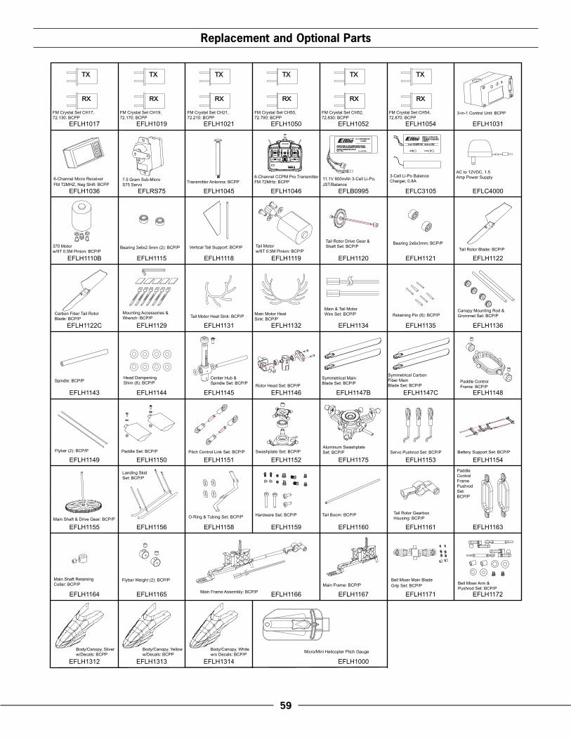
�9
EFLH1046 EFLB0995EFLRS75EFLH1036
EFLH1031EFLH1017
EFLH1000
EFLH1019 EFLH1021 EFLH1050 EFLH1052 EFLH1054
EFLC3105EFLH1045
EFLH1110B EFLH1115 EFLH1118 EFLH1119 EFLH1120 EFLH1121
EFLH1122C
EFLH1143
EFLH1135 EFLH1136EFLH1129 EFLH1131 EFLH1132 EFLH1134
EFLH1145EFLH1144 EFLH1146 EFLH1147CEFLH1147B EFLH1148
EFLH1149
EFLH1156
EFLH1150 EFLH1151 EFLH1152 EFLH1175 EFLH1153 EFLH1154
EFLH1155
EFLH1164
EFLH1312 EFLH1313 EFLH1314
EFLH1158 EFLH1159 EFLH1161
EFLH1166 EFLH1167 EFLH1171 EFLH1172
EFLH1160 EFLH1163
EFLH1165
EFLC4000
EFLH1122
Bell Mixer Main BladeGrip Set: BCP/P
RX
TXTX
RX
TXTXTXTX
RX RX RX RX
Tail Motorw/8T 0.5M Pinion: BCP/P
Tail Motor Heat Sink: BCP/P
Symmetrical Main Blade Set: BCP/PRotor Head Set: BCP/P
Symmetrical Carbon Fiber MainBlade Set: BCP/P
Mounting Accessories & Wrench: BCP/P
7.5 Gram Sub-Micro S75 Servo
Bearing 2x6x3mm: BCP/P
Carbon Fiber Tail Rotor Blade: BCP/P
Spindle: BCP/P
6-Channel CCPM Pro Transmitter FM 72MHz: BCPPTransmitter Antenna: BCPP
FM Crystal Set CH17, 72.130: BCPP
Micro/Mini Helicopter Pitch Gauge
FM Crystal Set CH19, 72.170: BCPP
FM Crystal Set CH21, 72.210: BCPP
FM Crystal Set CH50, 72.790: BCPP
FM Crystal Set CH52, 72.830: BCPP
FM Crystal Set CH54, 72.870: BCPP
Paddle Control Frame: BCP/P
Main & Tail Motor Wire Set: BCP/P Retaining Pin (6): BCP/P
Canopy Mounting Rod & Grommet Set: BCP/P
Head Dampening Shim (8): BCP/P
Main Motor Heat Sink: BCP/P
Bearing 3x6x2.5mm (2): BCP/P370 Motor w/9T 0.5M Pinion: BCP/P
Center Hub & Spindle Set: BCP/P
Tail Rotor Drive Gear &Shaft Set: BCP/PVertical Tail Support: BCP/P
3-Cell Li-Po Balance Charger, 0.8A
Tail Boom: BCP/P Tail Rotor Gearbox Housing: BCP/P
Hardware Set: BCP/P
PaddleControlFramePushrodSet:BCP/P
Main Shaft Retaining Collar: BCP/P
Main Frame Assembly: BCP/PMain Frame: BCP/P
Servo Pushrod Set: BCP/PPitch Control Link Set: BCP/P Swashplate Set: BCP/PAluminum Swashplate Set: BCP/P
Main Shaft & Drive Gear: BCP/P
Battery Support Set: BCP/PFlybar (2): BCP/P
Landing Skid Set: BCP/P
Paddle Set: BCP/P
O-Ring & Tubing Set: BCP/P
Flybar Weight (2): BCP/P
3-in-1 Control Unit: BCPP
6-Channel Micro Receiver FM 72MHZ, Neg Shift: BCPP
11.1V 800mAh 3-Cell Li-Po,JST/Balance
AC to 12VDC, 1.5 Amp Power Supply
Tail Rotor Blade: BCP/P
Bell Mixer Arm & Pushrod Set: BCP/P
Body/Canopy, Silverw/Decals: BCPP
Body/Canopy, Yelloww/Decals: BCPP
Body/Canopy, Whitew/o Decals: BCP/P
®
®
Replacement and Optional Parts

�0
001...... Flybar Paddle (2) ............................. EFLH1150002...... Nut (2) ............................................ EFLH1150003...... Flybar (1) ........................................ EFLH1149004...... Collar (2) ........................................ EFLH1148005...... Rotor Head Frame A (1) .................... EFLH1146006...... Pitch Control Link (4) ......................... EFLH1151007...... Threaded Rod (2) ............................. EFLH1151008...... Center Hub (1) ................................. EFLH1145009...... Paddle Control Frame Pushrod (2) ...... EFLH1163010...... Main Blade Hold-Down Plate A (2) ..... EFLH1147B011...... Flat Head Screw (2) ......................... EFLH1147B012...... Main Blade Hold-Down Plate B (2) ..... EFLH1147B013...... Socket Head Cap Screw (2) .............. EFLH1159014...... Bearing 3×6×2.5mm (10) ................. EFLH1115015...... Receiver .......................................... EFLH1036016...... Spindle (1) ...................................... EFLH1145017...... Bearing 7×13×4mm (1) .................... EFLH1152018...... Lower Swashplate (1) ....................... EFLH1152019...... Setscrew (5) ..................................... EFLH1159020...... Pinion Gear (1) ................................ EFLH1110B021...... Sub-Micro Servo (3) .......................... EFLRS75022...... Main Frame (1) ................................ EFLH1167023...... 3-in-1 Control Unit (1) ....................... EFLH1031024...... Silicone Tube Section (9) ................... EFLH1158025...... Strut (4) ........................................... EFLH1156026...... Main Motor Washer (2) .................... EFLH1110B027...... Main Motor Screw (2) ...................... EFLH1110B028...... Skid (2) ........................................... EFLH1156029...... Cap Head Screw (1) ........................ EFLH1145030...... Center Hub Cap (1) .......................... EFLH1145031...... Paddle Control Frame (1) .................. EFLH1148032...... Cap Head Screw (4) ........................ EFLH1146033...... Rotor Head Frame B (1) .................... EFLH1146034...... Rotor Head (1) ................................. EFLH1146035...... Retaining Pin (1) ............................... EFLH1135036...... Socket Head Cap Screw (2) .............. EFLH1159038...... O-Ring (2) ....................................... EFLH1158039...... Step Washer (4) ............................... EFLH1171040...... Washer (4) ...................................... EFLH1171
Please.see.your.favorite.retailer.or.visit.our.web.site.(www.E-fliteRC.com).to.find.the.latest.in.new.replacement.and.option.parts.releases.for.your.Blade™.CP.Pro .
Exploded View Parts Listing
041...... Cap Head Screw (2) ........................ EFLH1150042...... Main Blade (2) ................................ EFLH1147B043...... Swashplate Ball (1) ........................... EFLH1152044...... Upper Swashplate (1) ....................... EFLH1152045...... Servo Pushrod Control Link (3) ........... EFLH1153046...... Servo Pushrod Threaded Rod (3) ........ EFLH1153047...... Main Shaft Retaining Collar (1).......... EFLH1164048...... Battery Support (1) ........................... EFLH1154049...... Battery Pack (1) ............................... EFLB0995050...... Main Shaft & Drive Gear (1) ............. EFLH1155051...... Battery Support Rod Joiner (2) ........... EFLH1154052...... Battery Support Rod (2)..................... EFLH1154053...... Canopy Mount Rod (2) ..................... EFLH1136054...... Canopy (1) ...................................... EFLH1312055...... Canopy Mount Grommet (4) .............. EFLH1136056...... Tail Boom (1) ................................... EFLH1160057...... Tail Rotor Blade (1) ........................... EFLH1122058...... Vertical Tail Support (1) ..................... EFLH1118059...... Tail Rotor Drive Gear (1) ................... EFLH1120060...... Tail Motor Washer (2) ....................... EFLH1119061...... Tail Rotor Gearbox Housing (1) .......... EFLH1161062...... Bearing 2×6×3mm (2) ...................... EFLH1121063...... Tail Motor Pinion (1) ......................... EFLH1119064...... Tail Motor (1) ................................... EFLH1119065...... Tail Rotor Shaft (1) ............................ EFLH1120066...... Tail Rotor Shaft Stop (1) .................... EFLH1120067...... Main Motor (1) ................................ EFLH1110B069...... Flybar Weight Collar (2) ................... EFLH1165070...... Bell Mixer Main Blade Grip (2)…. ..... EFLH1171071...... Shim (2) .......................................... EFLH1172072...... Bushing (2) ...................................... EFLH1172073...... Bell Mixer Arm (2) ............................ EFLH1172074...... Washer (2) ...................................... EFLH1172075...... Pan Head Screw (2) ......................... EFLH1172076...... Bell Mixer Arm Pushrod (2)................ EFLH1172077...... Bearing Spacer (2) ........................... EFLH1171078...... Main Motor Heat Sink (1) ................. EFLH1132079...... Tail Motor Heat Sink (1) .................... EFLH1131
ExplodedView
ReferenceNumber
Description(QuantityRequired)
IncludedInItemNumber
ExplodedView
ReferenceNumber
Description(QuantityRequired)
IncludedInItemNumber
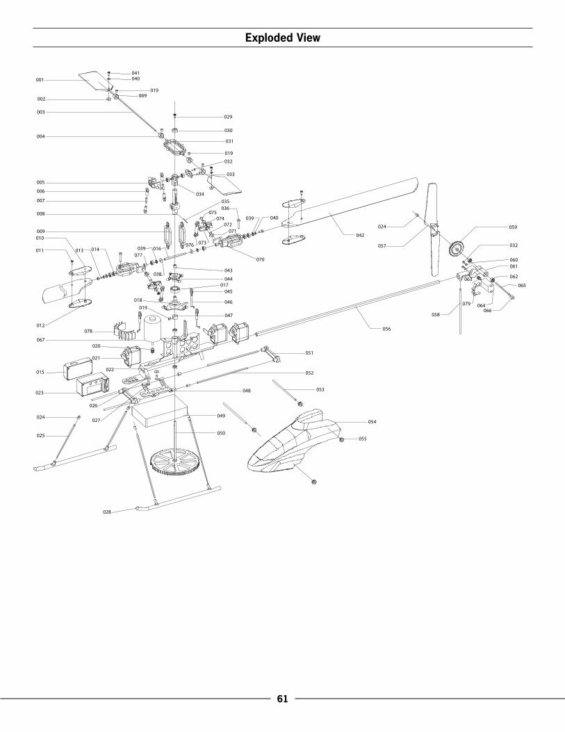
�1
063
009
008
007
010
011
006
005
004
003
002
001
032
033
019
031
030
029
041
069019
013 039014 016077
035
034
042
040
036
039
057
024
074075
070
025
024
067
023
012
015
050
049
048
047
046
045
043
044
027
022
020
021
054
052
051
053
073
078 056
066058
061
064
062
032
060
059
065
079
026
019
018
017
055
038
076
072071
028
040
Exploded View

��
Notes

��
Notes

9002
© 2006 Horizon Hobby, Inc. 4105 Fieldstone Road
Champaign, Illinois 61822 (877) 504-0233
www.E-fliteRC.com
®