Embed Size (px)
Citation preview

Specifications
Main Rotor Diameter ........................................................................................... 28.2 in (718mm)Tail Rotor Diameter ................................................................................................ 5.3 in (135mm)Height ................................................................................................................. 9.0 in (230mm)Length ................................................................................................................ 25.6 in (650mm)Weight without Battery ......................................................................... 18.0–18.5 oz (510–525 g)Weight with Battery .............................................................................. 23.0–24.5 oz (650–695 g)Motor ....................................................................... 420H brushless outrunner, 3800Kv (installed)ESC ................................................................................................... 25-amp brushless (installed)Battery ........................................................................ 3S 11.1V 1800–2200mAh Li-Po (required)Charger ............................................................................... 3S 11.1V Li-Po Compatible (required)Transmitter..................... 6+ channel with helicopter and 120-degree CCPM programming (required)Receiver ............................................................................................. 6+ channel micro (required)Servos ..................................................................................DS75H Digital Sub-Micro (4 installed)Gyro ..................................................................................... G110 Micro Heading Lock (installed)
2 3
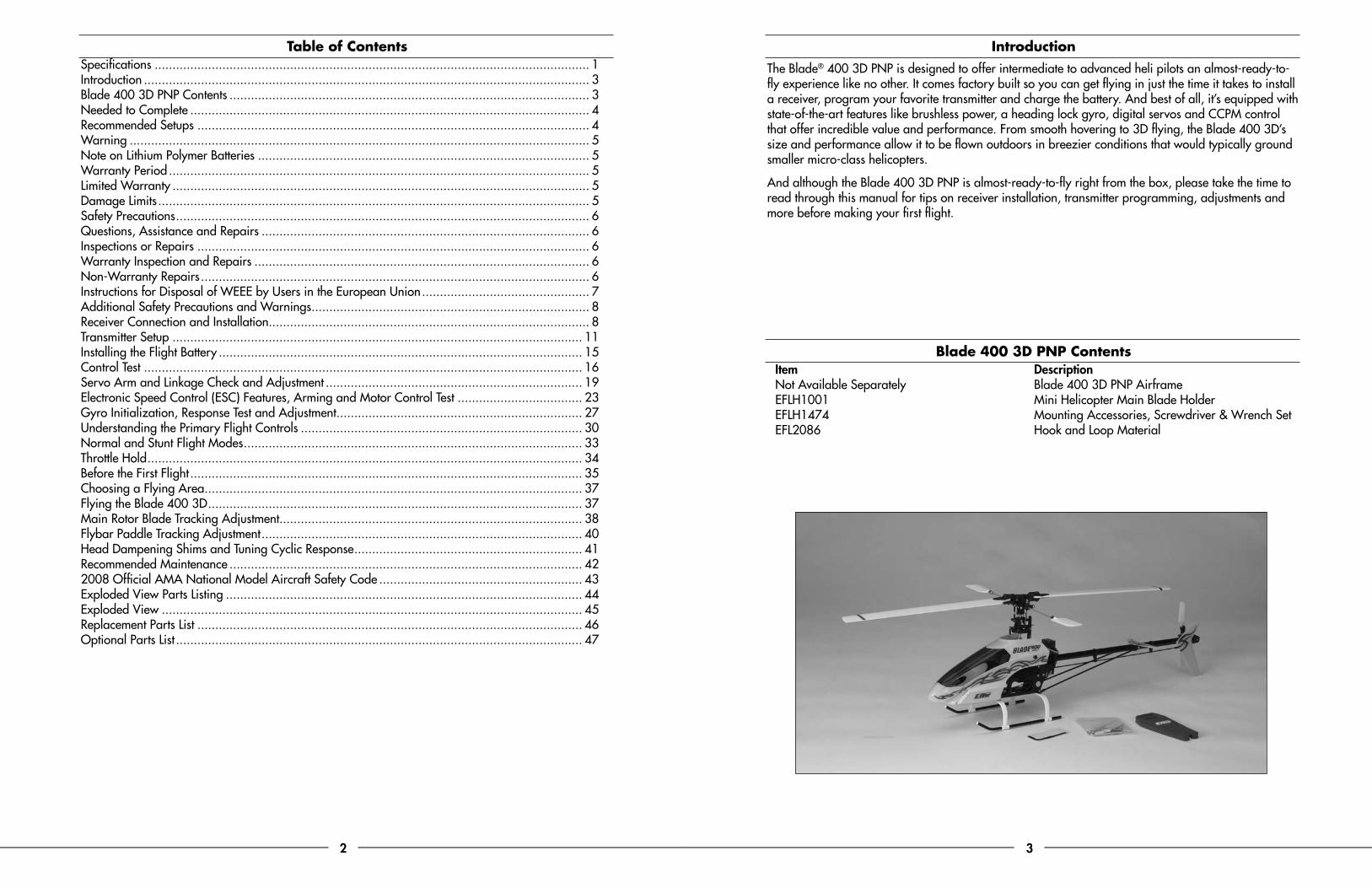
IntroductionThe Blade® 400 3D PNP is designed to offer intermediate to advanced heli pilots an almost-ready-to-fly experience like no other. It comes factory built so you can get flying in just the time it takes to install a receiver, program your favorite transmitter and charge the battery. And best of all, it’s equipped with state-of-the-art features like brushless power, a heading lock gyro, digital servos and CCPM control that offer incredible value and performance. From smooth hovering to 3D flying, the Blade 400 3D’s size and performance allow it to be flown outdoors in breezier conditions that would typically ground smaller micro-class helicopters.
And although the Blade 400 3D PNP is almost-ready-to-fly right from the box, please take the time to read through this manual for tips on receiver installation, transmitter programming, adjustments and more before making your first flight.
Blade 400 3D PNP ContentsItem DescriptionNot Available Separately Blade 400 3D PNP AirframeEFLH1001 Mini Helicopter Main Blade HolderEFLH1474 Mounting Accessories, Screwdriver & Wrench SetEFL2086 Hook and Loop Material
Table of ContentsSpecifications .......................................................................................................................... 1Introduction ............................................................................................................................. 3Blade 400 3D PNP Contents ..................................................................................................... 3Needed to Complete ................................................................................................................ 4Recommended Setups .............................................................................................................. 4Warning ................................................................................................................................. 5Note on Lithium Polymer Batteries ............................................................................................. 5Warranty Period ...................................................................................................................... 5Limited Warranty ..................................................................................................................... 5Damage Limits ......................................................................................................................... 5Safety Precautions .................................................................................................................... 6Questions, Assistance and Repairs ............................................................................................ 6Inspections or Repairs .............................................................................................................. 6Warranty Inspection and Repairs .............................................................................................. 6Non-Warranty Repairs ............................................................................................................. 6Instructions for Disposal of WEEE by Users in the European Union ............................................... 7Additional Safety Precautions and Warnings .............................................................................. 8Receiver Connection and Installation.......................................................................................... 8Transmitter Setup ................................................................................................................... 11Installing the Flight Battery ...................................................................................................... 15Control Test ........................................................................................................................... 16Servo Arm and Linkage Check and Adjustment ........................................................................ 19Electronic Speed Control (ESC) Features, Arming and Motor Control Test ................................... 23Gyro Initialization, Response Test and Adjustment ..................................................................... 27Understanding the Primary Flight Controls ............................................................................... 30Normal and Stunt Flight Modes ............................................................................................... 33Throttle Hold .......................................................................................................................... 34Before the First Flight .............................................................................................................. 35Choosing a Flying Area .......................................................................................................... 37Flying the Blade 400 3D ......................................................................................................... 37Main Rotor Blade Tracking Adjustment..................................................................................... 38Flybar Paddle Tracking Adjustment .......................................................................................... 40Head Dampening Shims and Tuning Cyclic Response ................................................................ 41Recommended Maintenance ................................................................................................... 422008 Official AMA National Model Aircraft Safety Code ......................................................... 43Exploded View Parts Listing .................................................................................................... 44Exploded View ...................................................................................................................... 45Replacement Parts List ............................................................................................................ 46Optional Parts List .................................................................................................................. 47
4 5
Needed to CompleteThe following items are required to complete your Blade 400 3D PNP:
• 6-channel (or greater) transmitter with helicopter and 120-degree CCPM programming
• 6-channel (or greater) micro receiver (end pin type is recommended for the best and most convenient installation)
• 3S 11.1V 1800-2200mAh Li-Po battery capable of 15C or greater discharge rates
• 3S 11.1V Li-Po compatible charger
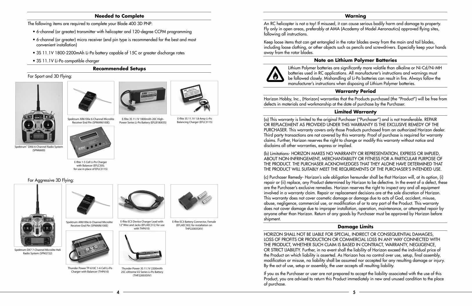
Recommended SetupsFor Sport and 3D Flying:
For Aggressive 3D Flying:
E-flite 3S 11.1V 1.8-Amp Li-Po Balancing Charger (EFLC3115)
Spektrum AR6100e 6-Channel Microlite Receiver End Pin (SPMAR6100E)
Spektrum AR6100e 6-Channel Microlite Receiver End Pin (SPMAR6100E)
WarningAn RC helicopter is not a toy! If misused, it can cause serious bodily harm and damage to property. Fly only in open areas, preferably at AMA (Academy of Model Aeronautics) approved flying sites, following all instructions.
Keep loose items that can get entangled in the rotor blades away from the main and tail blades, including loose clothing, or other objects such as pencils and screwdrivers. Especially keep your hands away from the rotor blades.
Note on Lithium Polymer BatteriesLithium Polymer batteries are significantly more volatile than alkaline or Ni-Cd/Ni-MH batteries used in RC applications. All manufacturer’s instructions and warnings must be followed closely. Mishandling of Li-Po batteries can result in fire. Always follow the manufacturer’s instructions when disposing of Lithium Polymer batteries.
Warranty PeriodHorizon Hobby, Inc., (Horizon) warranties that the Products purchased (the “Product”) will be free from defects in materials and workmanship at the date of purchase by the Purchaser.
Limited Warranty(a) This warranty is limited to the original Purchaser (“Purchaser”) and is not transferable. REPAIR OR REPLACEMENT AS PROVIDED UNDER THIS WARRANTY IS THE EXCLUSIVE REMEDY OF THE PURCHASER. This warranty covers only those Products purchased from an authorized Horizon dealer. Third party transactions are not covered by this warranty. Proof of purchase is required for warranty claims. Further, Horizon reserves the right to change or modify this warranty without notice and disclaims all other warranties, express or implied.
(b) Limitations- HORIZON MAKES NO WARRANTY OR REPRESENTATION, EXPRESS OR IMPLIED, ABOUT NON-INFRINGEMENT, MERCHANTABILITY OR FITNESS FOR A PARTICULAR PURPOSE OF THE PRODUCT. THE PURCHASER ACKNOWLEDGES THAT THEY ALONE HAVE DETERMINED THAT THE PRODUCT WILL SUITABLY MEET THE REQUIREMENTS OF THE PURCHASER’S INTENDED USE.
(c) Purchaser Remedy- Horizon’s sole obligation hereunder shall be that Horizon will, at its option, (i) repair or (ii) replace, any Product determined by Horizon to be defective. In the event of a defect, these are the Purchaser’s exclusive remedies. Horizon reserves the right to inspect any and all equipment involved in a warranty claim. Repair or replacement decisions are at the sole discretion of Horizon. This warranty does not cover cosmetic damage or damage due to acts of God, accident, misuse, abuse, negligence, commercial use, or modification of or to any part of the Product. This warranty does not cover damage due to improper installation, operation, maintenance, or attempted repair by anyone other than Horizon. Return of any goods by Purchaser must be approved by Horizon before shipment.
Damage LimitsHORIZON SHALL NOT BE LIABLE FOR SPECIAL, INDIRECT OR CONSEQUENTIAL DAMAGES, LOSS OF PROFITS OR PRODUCTION OR COMMERCIAL LOSS IN ANY WAY CONNECTED WITH THE PRODUCT, WHETHER SUCH CLAIM IS BASED IN CONTRACT, WARRANTY, NEGLIGENCE, OR STRICT LIABILITY. Further, in no event shall the liability of Horizon exceed the individual price of the Product on which liability is asserted. As Horizon has no control over use, setup, final assembly, modification or misuse, no liability shall be assumed nor accepted for any resulting damage or injury. By the act of use, setup or assembly, the user accepts all resulting liability.
If you as the Purchaser or user are not prepared to accept the liability associated with the use of this Product, you are advised to return this Product immediately in new and unused condition to the place of purchase.
E-flite 3S 11.1V 1800mAh 20C High-Power Series Li-Po Battery (EFLB18003S)
E-flite 1-5 Cell Li-Po Charger with Balancer (EFLC505;
for use in place of EFLC3115)
Spektrum™ DX6i 6-Channel Radio System (SPM6600)
Spektrum DX7 7-Channel Microlite Heli Radio System (SPM2722)
Thunder Power 3S 11.1V 2200mAh 25C eXtreme V2 Series Li-Po Battery
(THP22003SXV)
E-flite EC3 Device Charger Lead with 12” Wire and Jacks (EFLAEC312; for use
with THP610)
E-flite EC3 Battery Connector, Female (EFLAEC302; for installation on
THP22003SXV)
Thunder Power TP-610C 1-6 Cell Li-Po Charger with Balancer (THP610)
6 7
Law: These Terms are governed by Illinois law (without regard to conflict of law principals).
Safety PrecautionsThis is a sophisticated hobby Product and not a toy. It must be operated with caution and common sense and requires some basic mechanical ability. Failure to operate this Product in a safe and responsible manner could result in injury or damage to the Product or other property. This Product is not intended for use by children without direct adult supervision. The Product manual contains instructions for safety, operation and maintenance. It is essential to read and follow all the instructions and warnings in the manual, prior to assembly, setup or use, in order to operate correctly and avoid damage or injury.
Questions, Assistance and RepairsYour local hobby store and/or place of purchase cannot provide warranty support or repair. Once assembly, setup or use of the Product has been started, you must contact Horizon directly. This will enable Horizon to better answer your questions and service you in the event that you may need any assistance. For questions or assistance, please direct your email to [email protected], or call 877.504.0233 toll free to speak to a service technician.
Inspections or RepairsIf this Product needs to be inspected or repaired, please call for a Return Merchandise Authorization (RMA). Pack the Product securely using a shipping carton. Please note that original boxes may be included, but are not designed to withstand the rigors of shipping without additional protection. Ship via a carrier that provides tracking and insurance for lost or damaged parcels, as Horizon is not responsible for merchandise until it arrives and is accepted at our facility. A Service Repair Request is available at www.horizonhobby.com on the “Support” tab. If you do not have internet access, please include a letter with your complete name, street address, email address and phone number where you can be reached during business days, your RMA number, a list of the included items, method of payment for any non-warranty expenses and a brief summary of the problem. Your original sales receipt must also be included for warranty consideration. Be sure your name, address, and RMA number are clearly written on the outside of the shipping carton.
Warranty Inspection and RepairsTo receive warranty service, you must include your original sales receipt verifying the proof-of-purchase date. Provided warranty conditions have been met, your Product will be repaired or replaced free of charge. Repair or replacement decisions are at the sole discretion of Horizon Hobby.
Non-Warranty RepairsShould your repair not be covered by warranty the repair will be completed and payment will be required without notification or estimate of the expense unless the expense exceeds 50% of the retail purchase cost. By submitting the item for repair you are agreeing to payment of the repair without notification. Repair estimates are available upon request. You must include this request with your repair. Non-warranty repair estimates will be billed a minimum of ½ hour of labor. In addition you will be billed for return freight. Please advise us of your preferred method of payment. Horizon accepts money orders and cashiers checks, as well as Visa, MasterCard, American Express, and Discover cards. If you choose to pay by credit card, please include your credit card number and expiration date. Any repair left unpaid or unclaimed after 90 days will be considered abandoned and will be disposed of accordingly. Please note: non-warranty repair is only available on electronics and model engines.
United States: Electronics and engines requiring inspection or repair should be shipped to the following address:
Horizon Service Center 4105 Fieldstone Road
Champaign, Illinois 61822
All other products requiring warranty inspection or repair should be shipped to the following address:
Horizon Product Support 4105 Fieldstone Road
Champaign, Illinois 61822
Please call 877-504-0233 or e-mail us at [email protected] with any questions or concerns regarding this product or warranty.
European Union: Electronics and engines requiring inspection or repair should be shipped to the following address:
Horizon Hobby UK Units 1-4 Ployters Rd
Staple Tye Southern Way
Harlow Essex CM18 7NS United Kingdom
Please call +44 (0) 1279 641 097 or [email protected] with any questions or concerns regarding this product or warranty.
Instructions for Disposal of WEEE by Users in the European UnionThis product must not be disposed of with other waste. Instead, it is the user’s responsibility to dispose of their waste equipment by handing it over to a designated collection point for the recycling of waste electrical and electronic equipment. The separate collection and recycling of your waste equipment at the time of disposal will help to conserve natural resources and ensure that it is recycled in a manner that protects human health and the environment. For more information about where you can drop off your waste equipment for recycling, please contact your local city office, your household waste disposal service or where you purchased the product.
8 9
Additional Safety Precautions and WarningsAs the user of this product, you are solely responsible for operating it in a manner that does not endanger yourself and others or result in damage to the product or the property of others.
This model is controlled by a radio signal that is subject to interference from many sources outside your control. This interference can cause momentary loss of control so it is advisable to always keep a safe distance in all directions around your model, as this margin will help to avoid collisions or injury.
• Never operate your model with low transmitter batteries.
• Always operate your model in an open area away from cars, traffic, or people.
• Avoid operating your model in the street where injury or damage can occur.
• Never operate the model out into the street or populated areas for any reason.
• Carefully follow the directions and warnings for this and any optional support equipment (chargers, rechargeable battery packs, etc.) that you use.
• Keep all chemicals, small parts and anything electrical out of the reach of children.
• Moisture causes damage to electronics. Avoid water exposure to all equipment not specifically designed and protected for this purpose.
• Never lick or place any portion of your model in your mouth as it could cause serious injury or even death.
Receiver Connection and InstallationA 6-channel or greater micro receiver is required. We strongly recommend the use of a DSM (Digital Spectrum Modulation) equipped receiver (like the Spektrum AR6100e) and transmitter on 2.4GHz (like the Spektrum DX6i or DX7) for the ultimate in glitch-free performance. However, if you will be using a 72MHz radio system, we recommend the use of a PCM receiver. We also recommend that the receiver be equipped with “end pins” for the best and most convenient installation.
The following steps outline connection and installation of the receiver:
o Apply one or two sections of the included two-sided tape to the bottom of your chosen receiver. Be sure to leave the paper backing that remains on the other side of the tape in place until after completing the next step.
o Locate the six wire leads/connectors located near the rear of the main frame. While it is possible to connect these leads/connectors to the receiver after it’s been installed, it is easier to connect them to the receiver before installing it in the main frame. Please see the following lists and illustrations, while also referring to the manual for your transmitter, for proper connections:
For JR® and Spektrum™ Transmitters/Receivers
Channel 1 (THRO) Electronic Speed Control (ESC) ‘throttle’ lead
Channel 2 (AILE) Lower rear-mounted swashplate control ‘aileron’ servo lead
Channel 3 (ELEV) Forward-mounted swashplate control ‘elevator’ servo lead
Channel 4 (RUDD) Gyro ‘rudder’ lead
Channel 5 (GEAR) Gyro ‘auxiliary’ lead (the single yellow wire lead)
Channel 6 (AUX1) Upper rear-mounted swashplate control ‘pitch’ servo lead
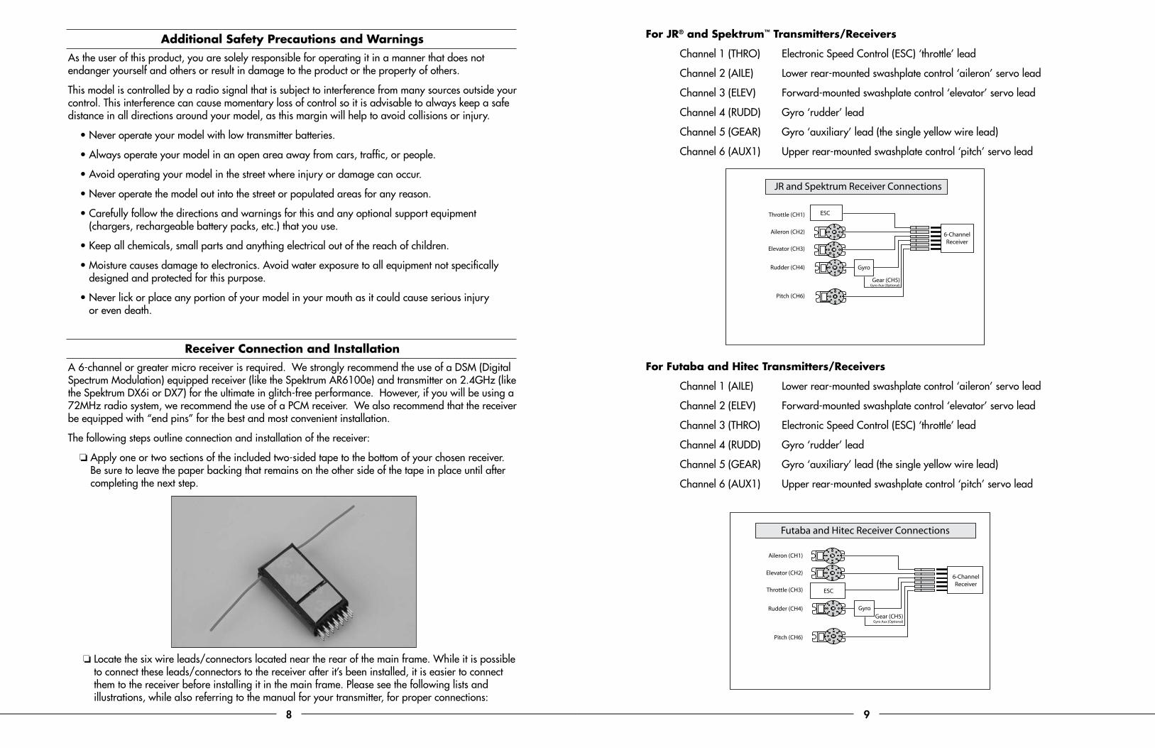
For Futaba and Hitec Transmitters/Receivers
Channel 1 (AILE) Lower rear-mounted swashplate control ‘aileron’ servo lead
Channel 2 (ELEV) Forward-mounted swashplate control ‘elevator’ servo lead
Channel 3 (THRO) Electronic Speed Control (ESC) ‘throttle’ lead
Channel 4 (RUDD) Gyro ‘rudder’ lead
Channel 5 (GEAR) Gyro ‘auxiliary’ lead (the single yellow wire lead)
Channel 6 (AUX1) Upper rear-mounted swashplate control ‘pitch’ servo lead
Aileron (CH1)
Elevator (CH2)
Throttle (CH3)
Rudder (CH4)
Pitch (CH6)
Gyro
ESC
Gear (CH5)Gyro Aux (Optional)
6-ChannelReceiver
Futaba and Hitec Receiver Connections
Throttle (CH1)
Aileron (CH2)
Elevator (CH3)
Rudder (CH4)
Pitch (CH6)
Gyro
ESC
Gear (CH5)Gyro Aux (Optional)
6-ChannelReceiver
JR and Spektrum Receiver Connections
10 11
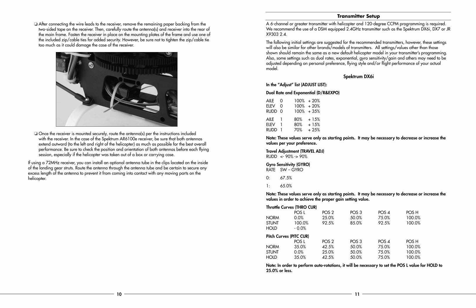
o After connecting the wire leads to the receiver, remove the remaining paper backing from the two-sided tape on the receiver. Then, carefully route the antenna(s) and receiver into the rear of the main frame. Fasten the receiver in place on the mounting plates of the frame and use one of the included zip/cable ties for added security. However, be sure not to tighten the zip/cable tie too much as it could damage the case of the receiver.
o Once the receiver is mounted securely, route the antenna(s) per the instructions included with the receiver. In the case of the Spektrum AR6100e receiver, be sure that both antennas extend outward (to the left and right of the helicopter) as much as possible for the best overall performance. Be sure to check the position and orientation of both antennas before each flying session, especially if the helicopter was taken out of a box or carrying case.
If using a 72MHz receiver, you can install an optional antenna tube in the clips located on the inside of the landing gear struts. Route the antenna through the antenna tube and be certain to secure any excess length of the antenna to prevent it from coming into contact with any moving parts on the helicopter.
Transmitter SetupA 6-channel or greater transmitter with helicopter and 120-degree CCPM programming is required. We recommend the use of a DSM equipped 2.4GHz transmitter such as the Spektrum DX6i, DX7 or JR X9303 2.4.
The following initial settings are suggested for the recommended transmitters, however, these settings will also be similar for other brands/models of transmitters. All settings/values other than those shown should remain the same as a new default helicopter model in your transmitter’s programming. Also, some settings such as dual rates, exponential, gyro sensitivity/gain and others may need to be adjusted depending on personal preference, flying style and/or flight performance of your actual model.
Spektrum DX6i
In the “Adjust” list (ADJUST LIST):
Dual Rate and Exponential (D/R&EXPO)
AILE 0 100% + 20% ELEV 0 100% + 20% RUDD 0 100% + 35%
AILE 1 80% + 15% ELEV 1 80% + 15% RUDD 1 70% + 25%
Note: These values serve only as starting points. It may be necessary to decrease or increase the values per your preference.
Travel Adjustment (TRAVEL ADJ) RUDD <- 90% -> 90%
Gyro Sensitivity (GYRO) RATE SW – GYRO
0: 67.5%
1: 65.0%
Note: These values serve only as starting points. It may be necessary to decrease or increase the values in order to achieve the proper gain setting value.
Throttle Curves (THRO CUR) POS L POS 2 POS 3 POS 4 POS H NORM 0.0% 25.0% 50.0% 75.0% 100.0% STUNT 100.0% 92.5% 85.0% 92.5% 100.0% HOLD - 0.0%
Pitch Curves (PITC CUR) POS L POS 2 POS 3 POS 4 POS H NORM 35.0% 42.5% 50.0% 75.0% 100.0% STUNT 0.0% 25.0% 50.0% 75.0% 100.0% HOLD 35.0% 42.5% 50.0% 75.0% 100.0%
Note: In order to perform auto-rotations, it will be necessary to set the POS L value for HOLD to 25.0% or less.
12 13
Swashplate Mixing (SWASH MIX) AILE - 75% ELEV - 75% PITC + 85%
In the “Setup” list (SETUP LIST): Servo Reversing (REVERSE) AILE – R RUDD – R
Swashplate Type (SWASH TYPE) CCPM 120*
Timer (TIMER) DOWN TIMER – 04:30
Spektrum DX7
In the “System Mode”:
Input Selection (INPUT SELECT) GEAR = GYRO
Swashplate Type (SWASH TYPE) 3 SERVOS 120*
In the “Function Mode”: Dual Rate and Exponential (D/R & EXP)
AILE POS–1 POS-0 EXP + 15% EXP +20 D/R 80% D/R 100%
ELEV POS–1 POS-0 EXP + 15% EXP +20% D/R 80% D/R 100%
RUDD POS-1 POS-0 EXP + 25% EXP +35% D/R 70% D/R 100%
Note: These values serve only as starting points. It may be necessary to decrease or increase the values per your preference.
Servo Reversing (REVERSING SW) Ch 4 (RUDD) Reverse (REV.) Ch 6 (PITC.) Reverse (REV.)
Travel Adjustment (TRAVEL ADJUST) RUDD L 90% R 90%
Swashplate Mixing (SWASH MIX) AILE + 65% ELEV + 65% PIT. + 80%
throttle hold (THRO HOLD) ACT HOLD Pos. HOLD SW 0.0%
Throttle Curves (THRO CURVE) Point–L Point–1 Point–2 Point–3 Point–H NORM 0.0% INH 50.0% INH 100.0% ST–1 100.0% INH 85.0% INH 100.0% ST–2 100.0% INH 100.0% INH 100.0%
Pitch Curves (PITCH CURVE) Point–L Point–1 Point–2 Point–3 Point–H NORM 35.0% INH 50.0% INH 100.0% ST–1 0.0% INH 50.0% INH 100.0% ST–2 0.0% INH 50.0% INH 100.0% HOLD 35.0% INH 50.0% INH 100.0%
Note: In order to perform auto-rotations, it will be necessary to set the Point-L value for HOLD to 25.0% or less.
Gyro Sensitivity (GYRO SENS) AUTO RATE: 0: 70% 1: 70%
Note: These values serve only as starting points. It may be necessary to decrease or increase the values in order to achieve the proper gain setting value.
Timer (TIMER) DOWN–T 4:30
JR X9303 2.4
In the “System Mode” (SYSTEM M.):
Swashplate Type (SWASH TYP) 3servos 120*
In the “Function Mode” (FUNC. LIST): Dual Rate and Exponential (D/R & EXP)
AILE POS-0 100% + 20% 100% + 20% ELEV POS-0 100% + 20% 100% + 20% RUDD POS-0 100% + 35% 100% + 35%
14 15
AILE POS–1 80% + 15% 80% + 15% ELEV POS–1 80% + 15% 80% + 15% RUDD POS–1 70% + 25% 70% + 25%
Note: These values serve only as starting points. It may be necessary to decrease or increase the values per your preference.
Servo Reversing (REV.SW) RUD Reverse (REV.) CH6 Reverse (REV.)
Travel Adjustment (TRVL ADJ.) RUDD L 90% R 90%
Swashplate Mixing (Swash Mix) AILE 65% ELEV 65% PIT. 80%
throttle hold (THRO HOLD) HOLD POS. 0.0%
Throttle Curves (THRO CURV) Point–L Point–1 Point–2 Point–3 Point–4 Point–5 Point–H NORM 0.0% INH INH 50.0% INH INH 100.0% ST–1 100.0% INH INH 85.0% INH INH 100.0% ST–2 100.0% INH INH 100.0% INH INH 100.0%
Pitch Curves (PIT. CURV) Point–L Point–1 Point–2 Point–3 Point–4 Point–5 Point–H NORM 35.0% INH INH 50.0% INH INH 100.0% ST–1 0.0% INH INH 50.0% INH INH 100.0% ST–2 0.0% INH INH 50.0% INH INH 100.0% HOLD 35.0% INH INH 50.0% INH INH 100.0%
Note: In order to perform auto-rotations, it will be necessary to set the Point-L value for HOLD to 25.0% or less.
Gyro Sensitivity (GYRO SENS) AUTO Pos. 0 70% Pos. 1 70% Pos. 2 70%
Note: These values serve only as starting points. It may be necessary to decrease or increase the values in order to achieve the proper gain setting value.
Timer (TIMER) DOWN–T 4:30
After programming your chosen transmitter with the suggested initial settings, install the flight battery and test the controls as outlined in the following sections in order to be sure that the settings are correct for proper control and performance.
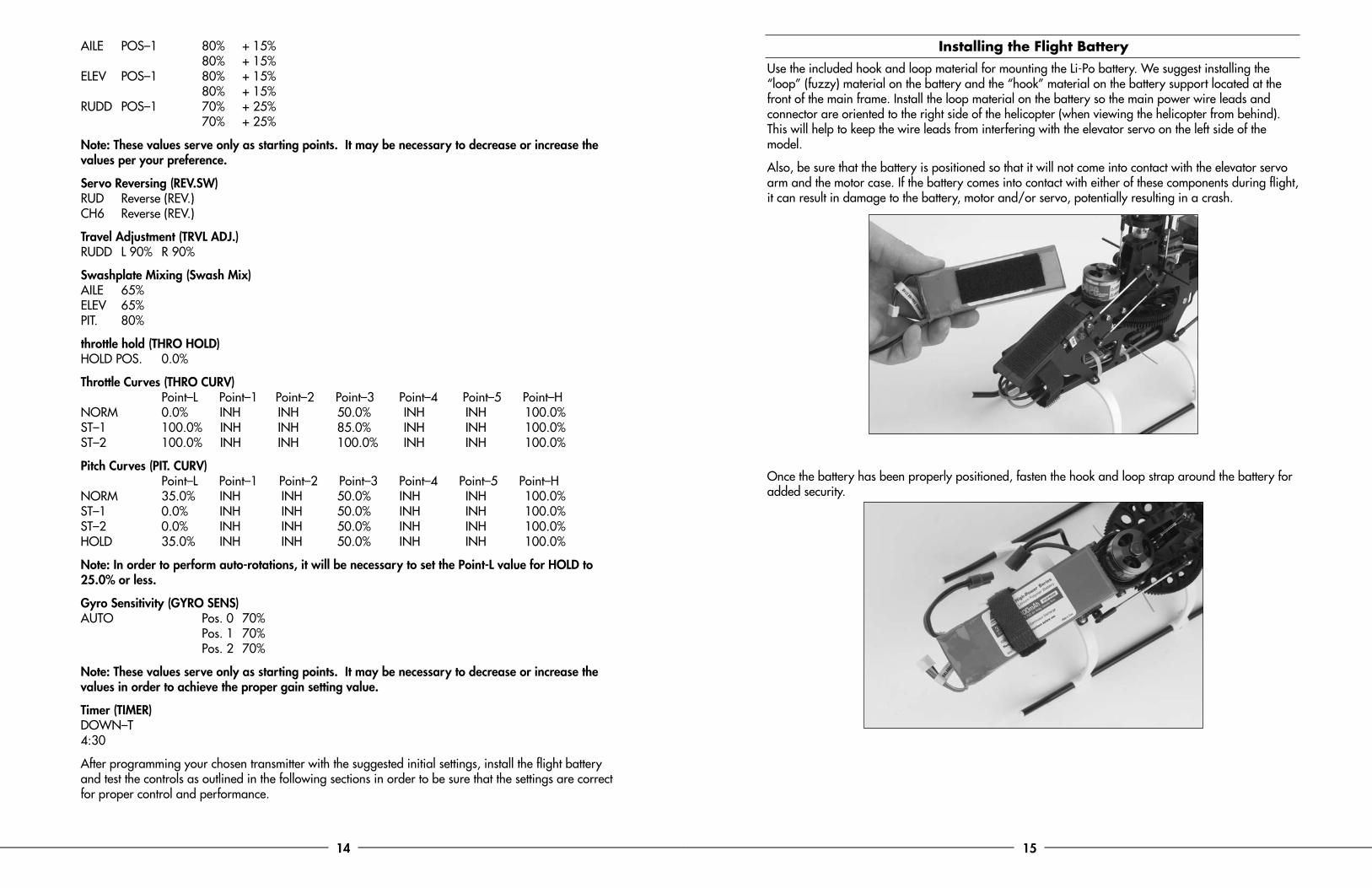
Installing the Flight BatteryUse the included hook and loop material for mounting the Li-Po battery. We suggest installing the “loop” (fuzzy) material on the battery and the “hook” material on the battery support located at the front of the main frame. Install the loop material on the battery so the main power wire leads and connector are oriented to the right side of the helicopter (when viewing the helicopter from behind). This will help to keep the wire leads from interfering with the elevator servo on the left side of the model.
Also, be sure that the battery is positioned so that it will not come into contact with the elevator servo arm and the motor case. If the battery comes into contact with either of these components during flight, it can result in damage to the battery, motor and/or servo, potentially resulting in a crash.
Once the battery has been properly positioned, fasten the hook and loop strap around the battery for added security.
16 17
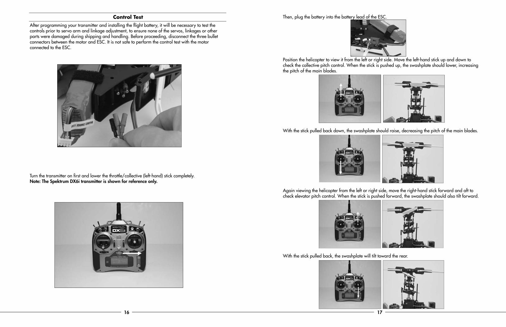
Control TestAfter programming your transmitter and installing the flight battery, it will be necessary to test the controls prior to servo arm and linkage adjustment, to ensure none of the servos, linkages or other parts were damaged during shipping and handling. Before proceeding, disconnect the three bullet connectors between the motor and ESC. It is not safe to perform the control test with the motor connected to the ESC.
Turn the transmitter on first and lower the throttle/collective (left-hand) stick completely. Note: The Spektrum DX6i transmitter is shown for reference only.
Then, plug the battery into the battery lead of the ESC.
Position the helicopter to view it from the left or right side. Move the left-hand stick up and down to check the collective pitch control. When the stick is pushed up, the swashplate should lower, increasing the pitch of the main blades.
With the stick pulled back down, the swashplate should raise, decreasing the pitch of the main blades.
Again viewing the helicopter from the left or right side, move the right-hand stick forward and aft to check elevator pitch control. When the stick is pushed forward, the swashplate should also tilt forward.
With the stick pulled back, the swashplate will tilt toward the rear.
18 19
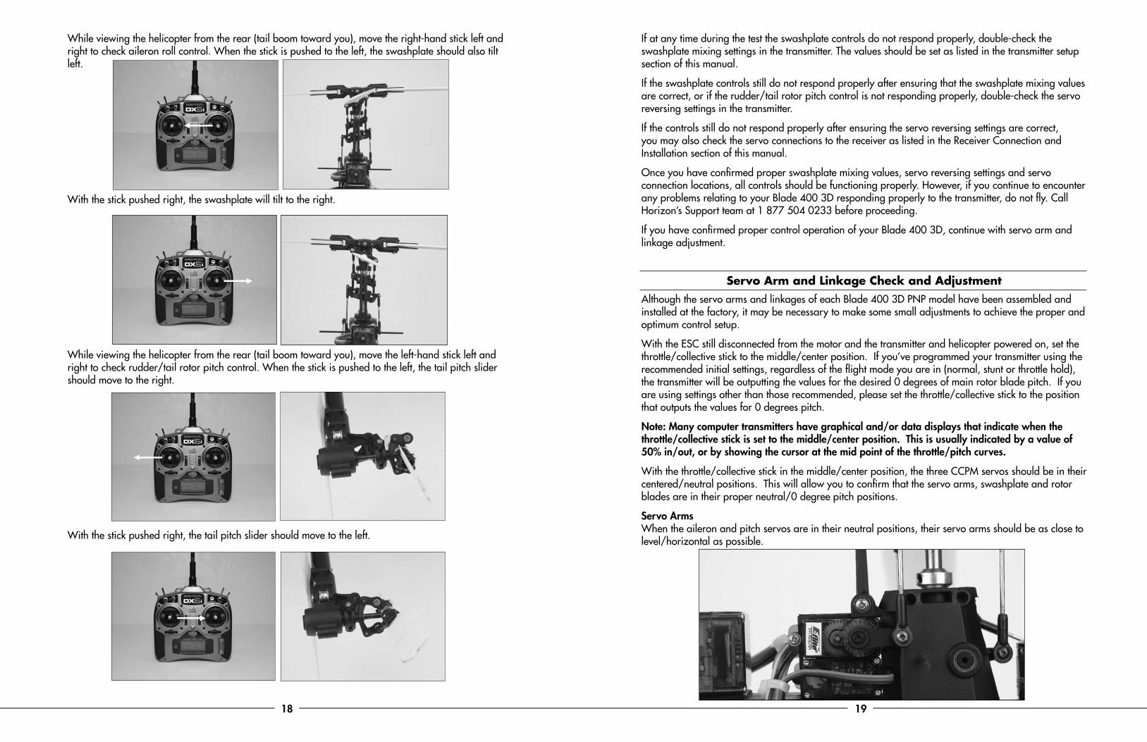
While viewing the helicopter from the rear (tail boom toward you), move the right-hand stick left and right to check aileron roll control. When the stick is pushed to the left, the swashplate should also tilt left.
With the stick pushed right, the swashplate will tilt to the right.
While viewing the helicopter from the rear (tail boom toward you), move the left-hand stick left and right to check rudder/tail rotor pitch control. When the stick is pushed to the left, the tail pitch slider should move to the right.
With the stick pushed right, the tail pitch slider should move to the left.
If at any time during the test the swashplate controls do not respond properly, double-check the swashplate mixing settings in the transmitter. The values should be set as listed in the transmitter setup section of this manual.
If the swashplate controls still do not respond properly after ensuring that the swashplate mixing values are correct, or if the rudder/tail rotor pitch control is not responding properly, double-check the servo reversing settings in the transmitter.
If the controls still do not respond properly after ensuring the servo reversing settings are correct, you may also check the servo connections to the receiver as listed in the Receiver Connection and Installation section of this manual.
Once you have confirmed proper swashplate mixing values, servo reversing settings and servo connection locations, all controls should be functioning properly. However, if you continue to encounter any problems relating to your Blade 400 3D responding properly to the transmitter, do not fly. Call Horizon’s Support team at 1 877 504 0233 before proceeding.
If you have confirmed proper control operation of your Blade 400 3D, continue with servo arm and linkage adjustment.
Servo Arm and Linkage Check and AdjustmentAlthough the servo arms and linkages of each Blade 400 3D PNP model have been assembled and installed at the factory, it may be necessary to make some small adjustments to achieve the proper and optimum control setup.
With the ESC still disconnected from the motor and the transmitter and helicopter powered on, set the throttle/collective stick to the middle/center position. If you’ve programmed your transmitter using the recommended initial settings, regardless of the flight mode you are in (normal, stunt or throttle hold), the transmitter will be outputting the values for the desired 0 degrees of main rotor blade pitch. If you are using settings other than those recommended, please set the throttle/collective stick to the position that outputs the values for 0 degrees pitch.
Note: Many computer transmitters have graphical and/or data displays that indicate when the throttle/collective stick is set to the middle/center position. This is usually indicated by a value of 50% in/out, or by showing the cursor at the mid point of the throttle/pitch curves.
With the throttle/collective stick in the middle/center position, the three CCPM servos should be in their centered/neutral positions. This will allow you to confirm that the servo arms, swashplate and rotor blades are in their proper neutral/0 degree pitch positions.
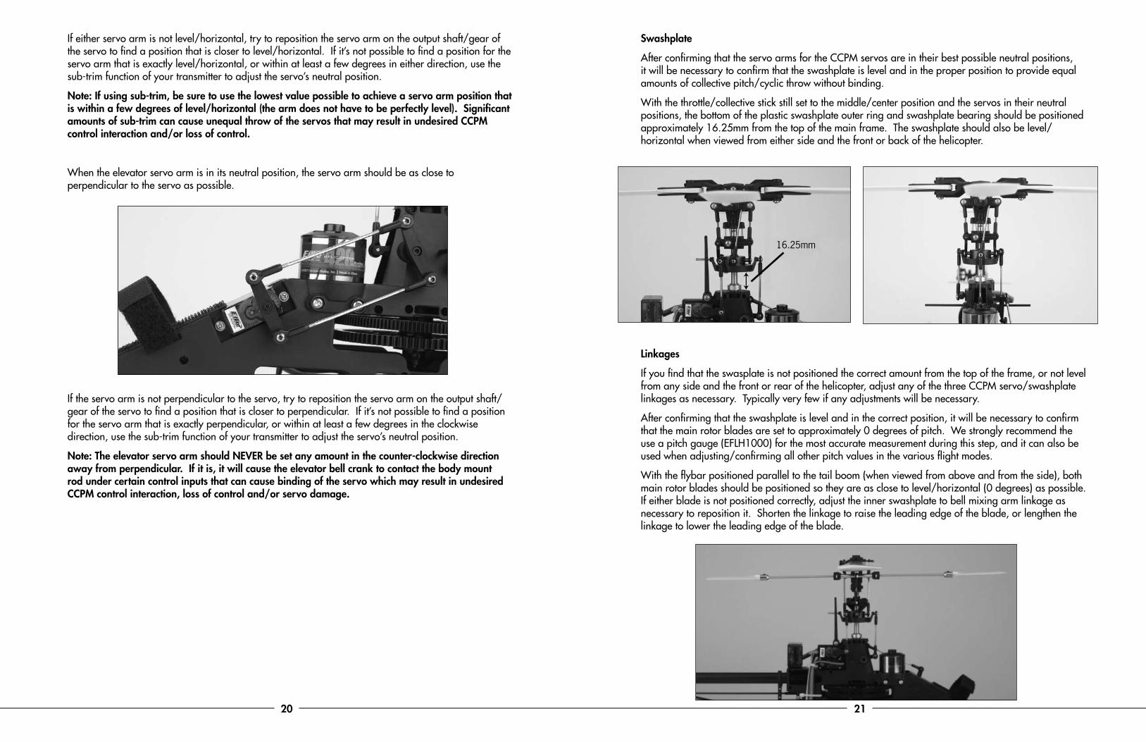
Servo Arms When the aileron and pitch servos are in their neutral positions, their servo arms should be as close to level/horizontal as possible.
20 21
If either servo arm is not level/horizontal, try to reposition the servo arm on the output shaft/gear of the servo to find a position that is closer to level/horizontal. If it’s not possible to find a position for the servo arm that is exactly level/horizontal, or within at least a few degrees in either direction, use the sub-trim function of your transmitter to adjust the servo’s neutral position.
Note: If using sub-trim, be sure to use the lowest value possible to achieve a servo arm position that is within a few degrees of level/horizontal (the arm does not have to be perfectly level). Significant amounts of sub-trim can cause unequal throw of the servos that may result in undesired CCPM control interaction and/or loss of control.
When the elevator servo arm is in its neutral position, the servo arm should be as close to perpendicular to the servo as possible.
If the servo arm is not perpendicular to the servo, try to reposition the servo arm on the output shaft/gear of the servo to find a position that is closer to perpendicular. If it’s not possible to find a position for the servo arm that is exactly perpendicular, or within at least a few degrees in the clockwise direction, use the sub-trim function of your transmitter to adjust the servo’s neutral position.
Note: The elevator servo arm should NEVER be set any amount in the counter-clockwise direction away from perpendicular. If it is, it will cause the elevator bell crank to contact the body mount rod under certain control inputs that can cause binding of the servo which may result in undesired CCPM control interaction, loss of control and/or servo damage.
Swashplate
After confirming that the servo arms for the CCPM servos are in their best possible neutral positions, it will be necessary to confirm that the swashplate is level and in the proper position to provide equal amounts of collective pitch/cyclic throw without binding.
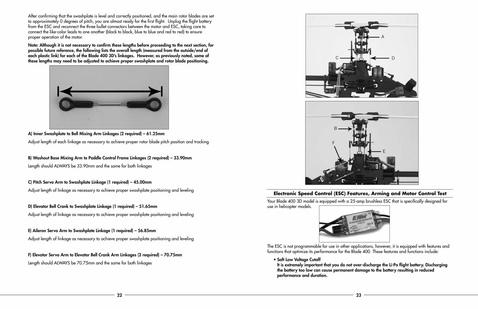
With the throttle/collective stick still set to the middle/center position and the servos in their neutral positions, the bottom of the plastic swashplate outer ring and swashplate bearing should be positioned approximately 16.25mm from the top of the main frame. The swashplate should also be level/horizontal when viewed from either side and the front or back of the helicopter.
Linkages
If you find that the swasplate is not positioned the correct amount from the top of the frame, or not level from any side and the front or rear of the helicopter, adjust any of the three CCPM servo/swashplate linkages as necessary. Typically very few if any adjustments will be necessary.
After confirming that the swashplate is level and in the correct position, it will be necessary to confirm that the main rotor blades are set to approximately 0 degrees of pitch. We strongly recommend the use a pitch gauge (EFLH1000) for the most accurate measurement during this step, and it can also be used when adjusting/confirming all other pitch values in the various flight modes.
With the flybar positioned parallel to the tail boom (when viewed from above and from the side), both main rotor blades should be positioned so they are as close to level/horizontal (0 degrees) as possible. If either blade is not positioned correctly, adjust the inner swashplate to bell mixing arm linkage as necessary to reposition it. Shorten the linkage to raise the leading edge of the blade, or lengthen the linkage to lower the leading edge of the blade.
16.25mm
22 23
After confirming that the swashplate is level and correctly positioned, and the main rotor blades are set to approximately 0 degrees of pitch, you are almost ready for the first flight. Unplug the flight battery from the ESC and reconnect the three bullet connectors between the motor and ESC, taking care to connect the like-color leads to one another (black to black, blue to blue and red to red) to ensure proper operation of the motor.
Note: Although it is not necessary to confirm these lengths before proceeding to the next section, for possible future reference, the following lists the overall length (measured from the outside/end of each plastic link) for each of the Blade 400 3D’s linkages. However, as previously noted, some of these lengths may need to be adjusted to achieve proper swashplate and rotor blade positioning.
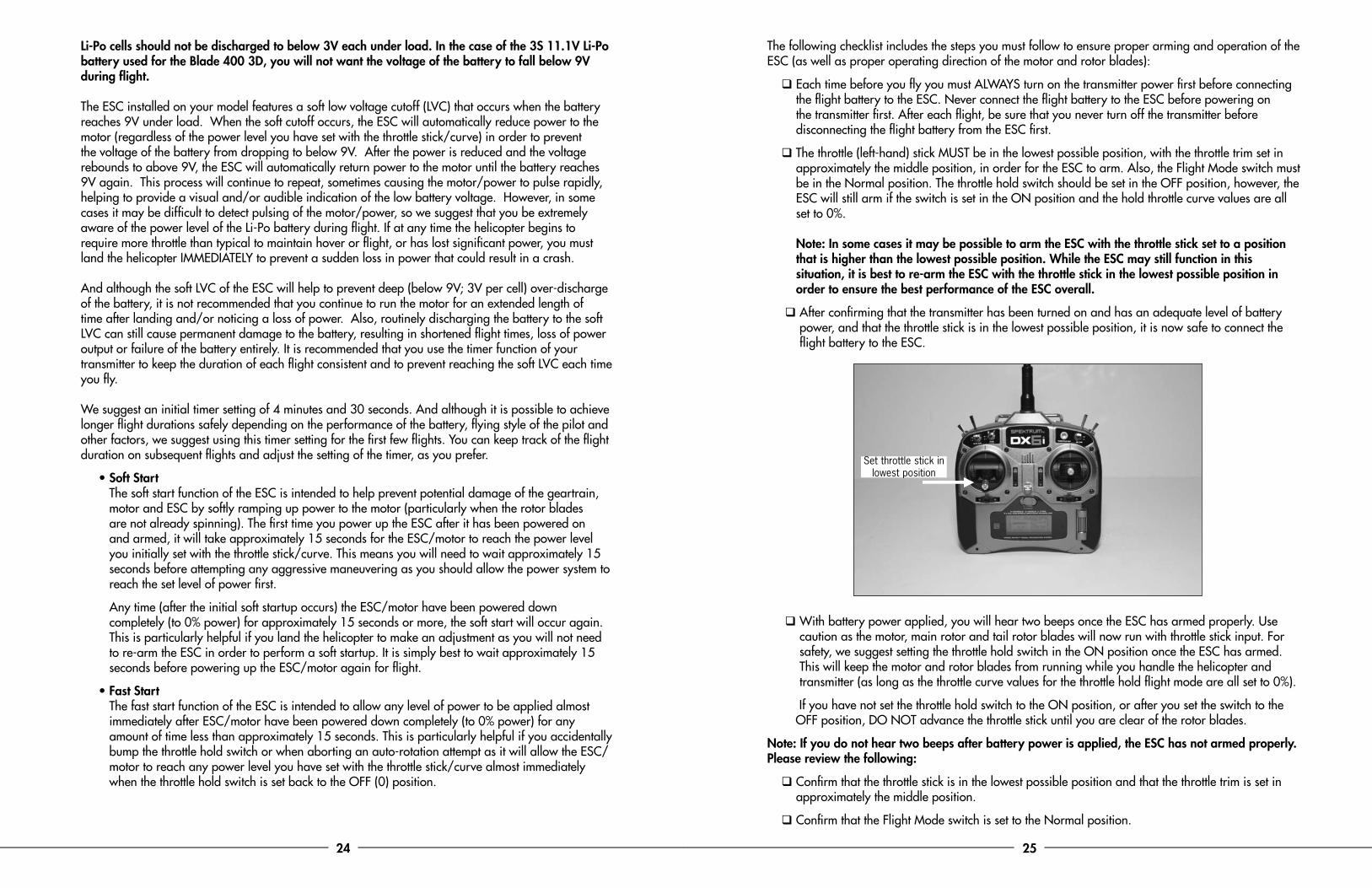
A) Inner Swashplate to Bell Mixing Arm Linkages (2 required) – 61.25mm
Adjust length of each linkage as necessary to achieve proper rotor blade pitch position and tracking
B) Washout Base Mixing Arm to Paddle Control Frame Linkages (2 required) – 33.90mm
Length should ALWAYS be 33.90mm and the same for both linkages
C) Pitch Servo Arm to Swashplate Linkage (1 required) – 45.00mm
Adjust length of linkage as necessary to achieve proper swashplate positioning and leveling
D) Elevator Bell Crank to Swashplate Linkage (1 required) – 51.65mm
Adjust length of linkage as necessary to achieve proper swashplate positioning and leveling
E) Aileron Servo Arm to Swashplate Linkage (1 required) – 56.85mm
Adjust length of linkage as necessary to achieve proper swashplate positioning and leveling
F) Elevator Servo Arm to Elevator Bell Crank Arm Linkages (2 required) – 70.75mm
Length should ALWAYS be 70.75mm and the same for both linkages
Electronic Speed Control (ESC) Features, Arming and Motor Control TestYour Blade 400 3D model is equipped with a 25-amp brushless ESC that is specifically designed for use in helicopter models.
The ESC is not programmable for use in other applications, however, it is equipped with features and functions that optimize its performance for the Blade 400. These features and functions include:
• Soft Low Voltage Cutoff It is extremely important that you do not over-discharge the Li-Po flight battery. Discharging the battery too low can cause permanent damage to the battery resulting in reduced performance and duration.
C
B
A
F
D
E
24 25
Li-Po cells should not be discharged to below 3V each under load. In the case of the 3S 11.1V Li-Po battery used for the Blade 400 3D, you will not want the voltage of the battery to fall below 9V during flight. The ESC installed on your model features a soft low voltage cutoff (LVC) that occurs when the battery reaches 9V under load. When the soft cutoff occurs, the ESC will automatically reduce power to the motor (regardless of the power level you have set with the throttle stick/curve) in order to prevent the voltage of the battery from dropping to below 9V. After the power is reduced and the voltage rebounds to above 9V, the ESC will automatically return power to the motor until the battery reaches 9V again. This process will continue to repeat, sometimes causing the motor/power to pulse rapidly, helping to provide a visual and/or audible indication of the low battery voltage. However, in some cases it may be difficult to detect pulsing of the motor/power, so we suggest that you be extremely aware of the power level of the Li-Po battery during flight. If at any time the helicopter begins to require more throttle than typical to maintain hover or flight, or has lost significant power, you must land the helicopter IMMEDIATELY to prevent a sudden loss in power that could result in a crash. And although the soft LVC of the ESC will help to prevent deep (below 9V; 3V per cell) over-discharge of the battery, it is not recommended that you continue to run the motor for an extended length of time after landing and/or noticing a loss of power. Also, routinely discharging the battery to the soft LVC can still cause permanent damage to the battery, resulting in shortened flight times, loss of power output or failure of the battery entirely. It is recommended that you use the timer function of your transmitter to keep the duration of each flight consistent and to prevent reaching the soft LVC each time you fly. We suggest an initial timer setting of 4 minutes and 30 seconds. And although it is possible to achieve longer flight durations safely depending on the performance of the battery, flying style of the pilot and other factors, we suggest using this timer setting for the first few flights. You can keep track of the flight duration on subsequent flights and adjust the setting of the timer, as you prefer.
• Soft Start The soft start function of the ESC is intended to help prevent potential damage of the geartrain, motor and ESC by softly ramping up power to the motor (particularly when the rotor blades are not already spinning). The first time you power up the ESC after it has been powered on and armed, it will take approximately 15 seconds for the ESC/motor to reach the power level you initially set with the throttle stick/curve. This means you will need to wait approximately 15 seconds before attempting any aggressive maneuvering as you should allow the power system to reach the set level of power first.
Any time (after the initial soft startup occurs) the ESC/motor have been powered down completely (to 0% power) for approximately 15 seconds or more, the soft start will occur again. This is particularly helpful if you land the helicopter to make an adjustment as you will not need to re-arm the ESC in order to perform a soft startup. It is simply best to wait approximately 15 seconds before powering up the ESC/motor again for flight.
• Fast Start The fast start function of the ESC is intended to allow any level of power to be applied almost immediately after ESC/motor have been powered down completely (to 0% power) for any amount of time less than approximately 15 seconds. This is particularly helpful if you accidentally bump the throttle hold switch or when aborting an auto-rotation attempt as it will allow the ESC/motor to reach any power level you have set with the throttle stick/curve almost immediately when the throttle hold switch is set back to the OFF (0) position.
The following checklist includes the steps you must follow to ensure proper arming and operation of the ESC (as well as proper operating direction of the motor and rotor blades):
q Each time before you fly you must ALWAYS turn on the transmitter power first before connecting the flight battery to the ESC. Never connect the flight battery to the ESC before powering on the transmitter first. After each flight, be sure that you never turn off the transmitter before disconnecting the flight battery from the ESC first.
q The throttle (left-hand) stick MUST be in the lowest possible position, with the throttle trim set in approximately the middle position, in order for the ESC to arm. Also, the Flight Mode switch must be in the Normal position. The throttle hold switch should be set in the OFF position, however, the ESC will still arm if the switch is set in the ON position and the hold throttle curve values are all set to 0%. Note: In some cases it may be possible to arm the ESC with the throttle stick set to a position that is higher than the lowest possible position. While the ESC may still function in this situation, it is best to re-arm the ESC with the throttle stick in the lowest possible position in order to ensure the best performance of the ESC overall.
q After confirming that the transmitter has been turned on and has an adequate level of battery power, and that the throttle stick is in the lowest possible position, it is now safe to connect the flight battery to the ESC.
q With battery power applied, you will hear two beeps once the ESC has armed properly. Use caution as the motor, main rotor and tail rotor blades will now run with throttle stick input. For safety, we suggest setting the throttle hold switch in the ON position once the ESC has armed. This will keep the motor and rotor blades from running while you handle the helicopter and transmitter (as long as the throttle curve values for the throttle hold flight mode are all set to 0%).
If you have not set the throttle hold switch to the ON position, or after you set the switch to the OFF position, DO NOT advance the throttle stick until you are clear of the rotor blades.
Note: If you do not hear two beeps after battery power is applied, the ESC has not armed properly. Please review the following:
q Confirm that the throttle stick is in the lowest possible position and that the throttle trim is set in approximately the middle position.
q Confirm that the Flight Mode switch is set to the Normal position.
Set throttle stick in lowest position
26 27
q Confirm that the low position value for the normal throttle curve is set to 0%.
q Confirm that the travel adjustment value for the throttle channel is set to 100% in the low position.
If the ESC will not arm after confirming the details listed above, contact Horizon Hobby’s Product Support staff at 1 877 504 0233 before proceeding.
q Once you have placed the helicopter in a safe area, free of obstructions, and are clear of the rotor blades, you can safely begin to power up the model to confirm proper operation and operating direction of the motor and rotor blades.
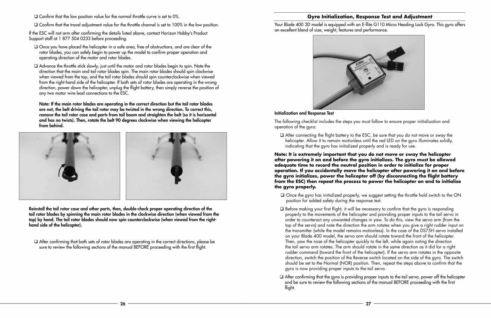
q Advance the throttle stick slowly, just until the motor and rotor blades begin to spin. Note the direction that the main and tail rotor blades spin. The main rotor blades should spin clockwise when viewed from the top, and the tail rotor blades should spin counterclockwise when viewed from the right-hand side of the helicopter. If both sets of rotor blades are operating in the wrong direction, power down the helicopter, unplug the flight battery, then simply reverse the position of any two motor wire lead connections to the ESC. Note: If the main rotor blades are operating in the correct direction but the tail rotor blades are not, the belt driving the tail rotor may be twisted in the wrong direction. To correct this, remove the tail rotor case and parts from tail boom and straighten the belt (so it is horizontal and has no twists). Then, rotate the belt 90 degrees clockwise when viewing the helicopter from behind.
Reinstall the tail rotor case and other parts, then, double-check proper operating direction of the tail rotor blades by spinning the main rotor blades in the clockwise direction (when viewed from the top) by hand. The tail rotor blades should now spin counterclockwise (when viewed from the right-hand side of the helicopter).
q After confirming that both sets of rotor blades are operating in the correct directions, please be sure to review the following sections of the manual BEFORE proceeding with the first flight.
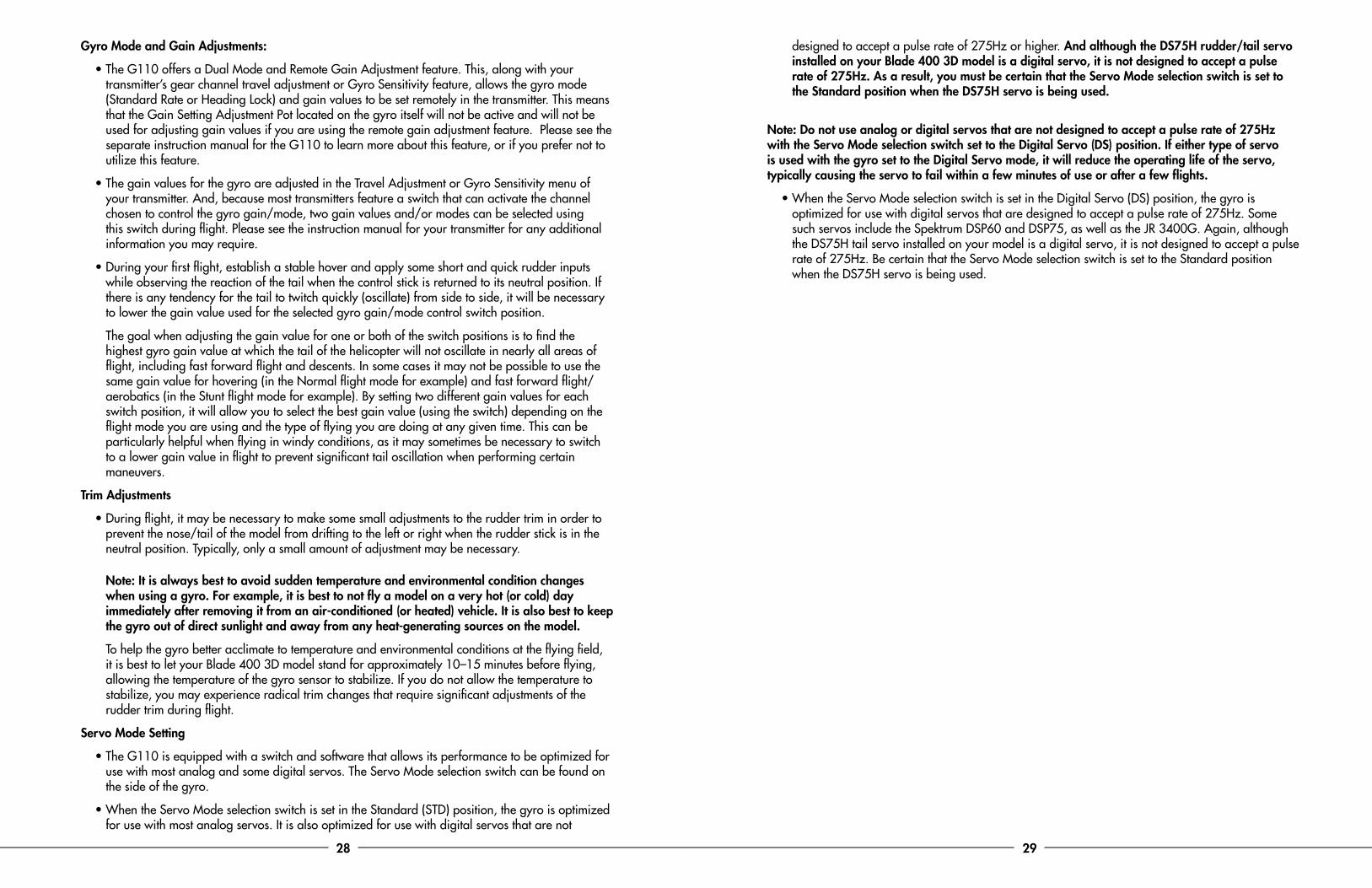
Gyro Initialization, Response Test and AdjustmentYour Blade 400 3D model is equipped with an E-flite G110 Micro Heading Lock Gyro. This gyro offers an excellent blend of size, weight, features and performance.
Initialization and Response Test
The following checklist includes the steps you must follow to ensure proper initialization and operation of the gyro:
q After connecting the flight battery to the ESC, be sure that you do not move or sway the helicopter. Allow it to remain motionless until the red LED on the gyro illuminates solidly, indicating that the gyro has initialized properly and is ready for use.
Note: It is extremely important that you do not move or sway the helicopter after powering it on and before the gyro initializes. The gyro must be allowed adequate time to record the neutral position in order to initialize for proper operation. If you accidentally move the helicopter after powering it on and before the gyro initializes, power the helicopter off (by disconnecting the flight battery from the ESC) then repeat the process to power the helicopter on and to initialize the gyro properly.
q Once the gyro has initialized properly, we suggest setting the throttle hold switch to the ON position for added safety during the response test.
q Before making your first flight, it will be necessary to confirm that the gyro is responding properly to the movements of the helicopter and providing proper inputs to the tail servo in order to counteract any unwanted changes in yaw. To do this, view the servo arm (from the top of the servo) and note the direction the arm rotates when you give a right rudder input on the transmitter (while the model remains motionless). In the case of the DS75H servo installed on your Blade 400 model, the servo arm should rotate toward the front of the helicopter. Then, yaw the nose of the helicopter quickly to the left, while again noting the direction the tail servo arm rotates. The arm should rotate in the same direction as it did for a right rudder command (toward the front of the helicopter). If the servo arm rotates in the opposite direction, switch the position of the Reverse switch located on the side of the gyro. The switch should be set to the Normal (NOR) position. Then, repeat the steps above to confirm that the gyro is now providing proper inputs to the tail servo.
q After confirming that the gyro is providing proper inputs to the tail servo, power off the helicopter and be sure to review the following sections of the manual BEFORE proceeding with the first flight.
28 29
Gyro Mode and Gain Adjustments:
• The G110 offers a Dual Mode and Remote Gain Adjustment feature. This, along with your transmitter’s gear channel travel adjustment or Gyro Sensitivity feature, allows the gyro mode (Standard Rate or Heading Lock) and gain values to be set remotely in the transmitter. This means that the Gain Setting Adjustment Pot located on the gyro itself will not be active and will not be used for adjusting gain values if you are using the remote gain adjustment feature. Please see the separate instruction manual for the G110 to learn more about this feature, or if you prefer not to utilize this feature.
• The gain values for the gyro are adjusted in the Travel Adjustment or Gyro Sensitivity menu of your transmitter. And, because most transmitters feature a switch that can activate the channel chosen to control the gyro gain/mode, two gain values and/or modes can be selected using this switch during flight. Please see the instruction manual for your transmitter for any additional information you may require.
• During your first flight, establish a stable hover and apply some short and quick rudder inputs while observing the reaction of the tail when the control stick is returned to its neutral position. If there is any tendency for the tail to twitch quickly (oscillate) from side to side, it will be necessary to lower the gain value used for the selected gyro gain/mode control switch position.
The goal when adjusting the gain value for one or both of the switch positions is to find the highest gyro gain value at which the tail of the helicopter will not oscillate in nearly all areas of flight, including fast forward flight and descents. In some cases it may not be possible to use the same gain value for hovering (in the Normal flight mode for example) and fast forward flight/aerobatics (in the Stunt flight mode for example). By setting two different gain values for each switch position, it will allow you to select the best gain value (using the switch) depending on the flight mode you are using and the type of flying you are doing at any given time. This can be particularly helpful when flying in windy conditions, as it may sometimes be necessary to switch to a lower gain value in flight to prevent significant tail oscillation when performing certain maneuvers.
Trim Adjustments
• During flight, it may be necessary to make some small adjustments to the rudder trim in order to prevent the nose/tail of the model from drifting to the left or right when the rudder stick is in the neutral position. Typically, only a small amount of adjustment may be necessary. Note: It is always best to avoid sudden temperature and environmental condition changes when using a gyro. For example, it is best to not fly a model on a very hot (or cold) day immediately after removing it from an air-conditioned (or heated) vehicle. It is also best to keep the gyro out of direct sunlight and away from any heat-generating sources on the model.
To help the gyro better acclimate to temperature and environmental conditions at the flying field, it is best to let your Blade 400 3D model stand for approximately 10–15 minutes before flying, allowing the temperature of the gyro sensor to stabilize. If you do not allow the temperature to stabilize, you may experience radical trim changes that require significant adjustments of the rudder trim during flight.
Servo Mode Setting
• The G110 is equipped with a switch and software that allows its performance to be optimized for use with most analog and some digital servos. The Servo Mode selection switch can be found on the side of the gyro.
• When the Servo Mode selection switch is set in the Standard (STD) position, the gyro is optimized for use with most analog servos. It is also optimized for use with digital servos that are not
designed to accept a pulse rate of 275Hz or higher. And although the DS75H rudder/tail servo installed on your Blade 400 3D model is a digital servo, it is not designed to accept a pulse rate of 275Hz. As a result, you must be certain that the Servo Mode selection switch is set to the Standard position when the DS75H servo is being used.
Note: Do not use analog or digital servos that are not designed to accept a pulse rate of 275Hz with the Servo Mode selection switch set to the Digital Servo (DS) position. If either type of servo is used with the gyro set to the Digital Servo mode, it will reduce the operating life of the servo, typically causing the servo to fail within a few minutes of use or after a few flights.
• When the Servo Mode selection switch is set in the Digital Servo (DS) position, the gyro is optimized for use with digital servos that are designed to accept a pulse rate of 275Hz. Some such servos include the Spektrum DSP60 and DSP75, as well as the JR 3400G. Again, although the DS75H tail servo installed on your model is a digital servo, it is not designed to accept a pulse rate of 275Hz. Be certain that the Servo Mode selection switch is set to the Standard position when the DS75H servo is being used.
30 31
Understanding the Primary Flight ControlsIf you are not familiar with the primary flight controls of your Blade 400 3D, please take a few minutes to familiarize yourself with them before proceeding and before attempting your first flight.
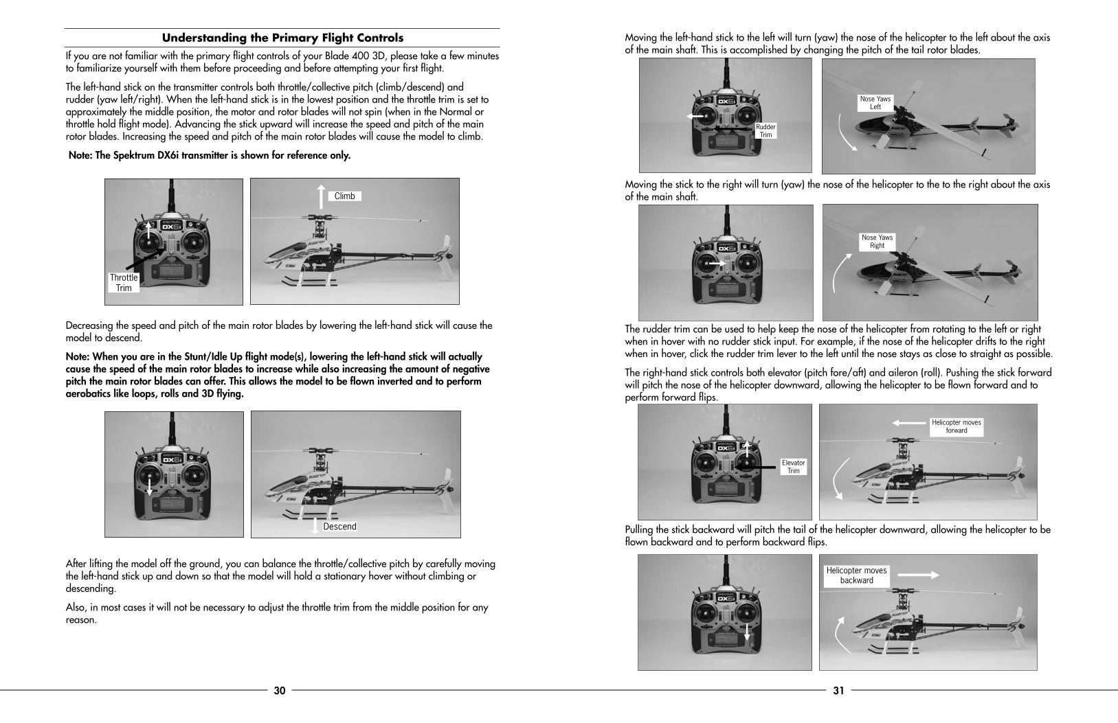
The left-hand stick on the transmitter controls both throttle/collective pitch (climb/descend) and rudder (yaw left/right). When the left-hand stick is in the lowest position and the throttle trim is set to approximately the middle position, the motor and rotor blades will not spin (when in the Normal or throttle hold flight mode). Advancing the stick upward will increase the speed and pitch of the main rotor blades. Increasing the speed and pitch of the main rotor blades will cause the model to climb.
Note: The Spektrum DX6i transmitter is shown for reference only.
Decreasing the speed and pitch of the main rotor blades by lowering the left-hand stick will cause the model to descend.
Note: When you are in the Stunt/Idle Up flight mode(s), lowering the left-hand stick will actually cause the speed of the main rotor blades to increase while also increasing the amount of negative pitch the main rotor blades can offer. This allows the model to be flown inverted and to perform aerobatics like loops, rolls and 3D flying.
After lifting the model off the ground, you can balance the throttle/collective pitch by carefully moving the left-hand stick up and down so that the model will hold a stationary hover without climbing or descending.
Also, in most cases it will not be necessary to adjust the throttle trim from the middle position for any reason.
Moving the left-hand stick to the left will turn (yaw) the nose of the helicopter to the left about the axis of the main shaft. This is accomplished by changing the pitch of the tail rotor blades.
Moving the stick to the right will turn (yaw) the nose of the helicopter to the to the right about the axis of the main shaft.
The rudder trim can be used to help keep the nose of the helicopter from rotating to the left or right when in hover with no rudder stick input. For example, if the nose of the helicopter drifts to the right when in hover, click the rudder trim lever to the left until the nose stays as close to straight as possible.
The right-hand stick controls both elevator (pitch fore/aft) and aileron (roll). Pushing the stick forward will pitch the nose of the helicopter downward, allowing the helicopter to be flown forward and to perform forward flips.
Pulling the stick backward will pitch the tail of the helicopter downward, allowing the helicopter to be flown backward and to perform backward flips.
Climb
Throttle Trim
Descend
Elevator Trim
Helicopter moves forward
Nose Yaws Right
Rudder Trim
Nose Yaws Left
Helicopter moves backward
32 33
The elevator trim can be used to help keep the helicopter from drifting forward or backward when in hover with no elevator stick input. For example, if the helicopter drifts forward when in hover, click the elevator trim lever downward until the helicopter hovers as level as possible with no forward drifting.
Moving the stick to the left will roll the helicopter to the left, allowing the helicopter to be flown to the left and to perform left-hand rolls.
Moving the stick to the right will roll the helicopter to the right, allowing the helicopter to be flown to the right and to perform right-hand rolls.
The aileron trim can be used to help keep the helicopter from drifting left or right when in hover with no aileron stick input. For example, if the helicopter drifts to the right when in hover, click the aileron trim lever to the left until the helicopter hovers as level as possible with no drifting to the right.
Once you have become familiar with the primary controls of the helicopter, you are almost ready to fly.
Normal and Stunt Flight ModesYour chosen transmitter should feature a Flight Mode switch. This switch allows you to toggle between the Normal and Stunt/Idle Up flight mode(s) during flight.
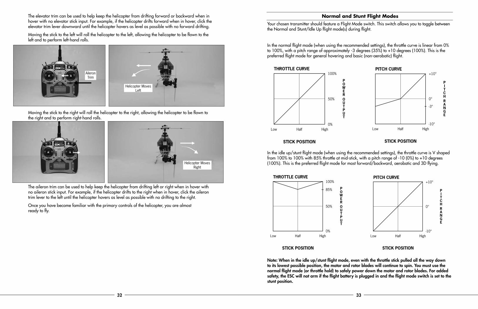
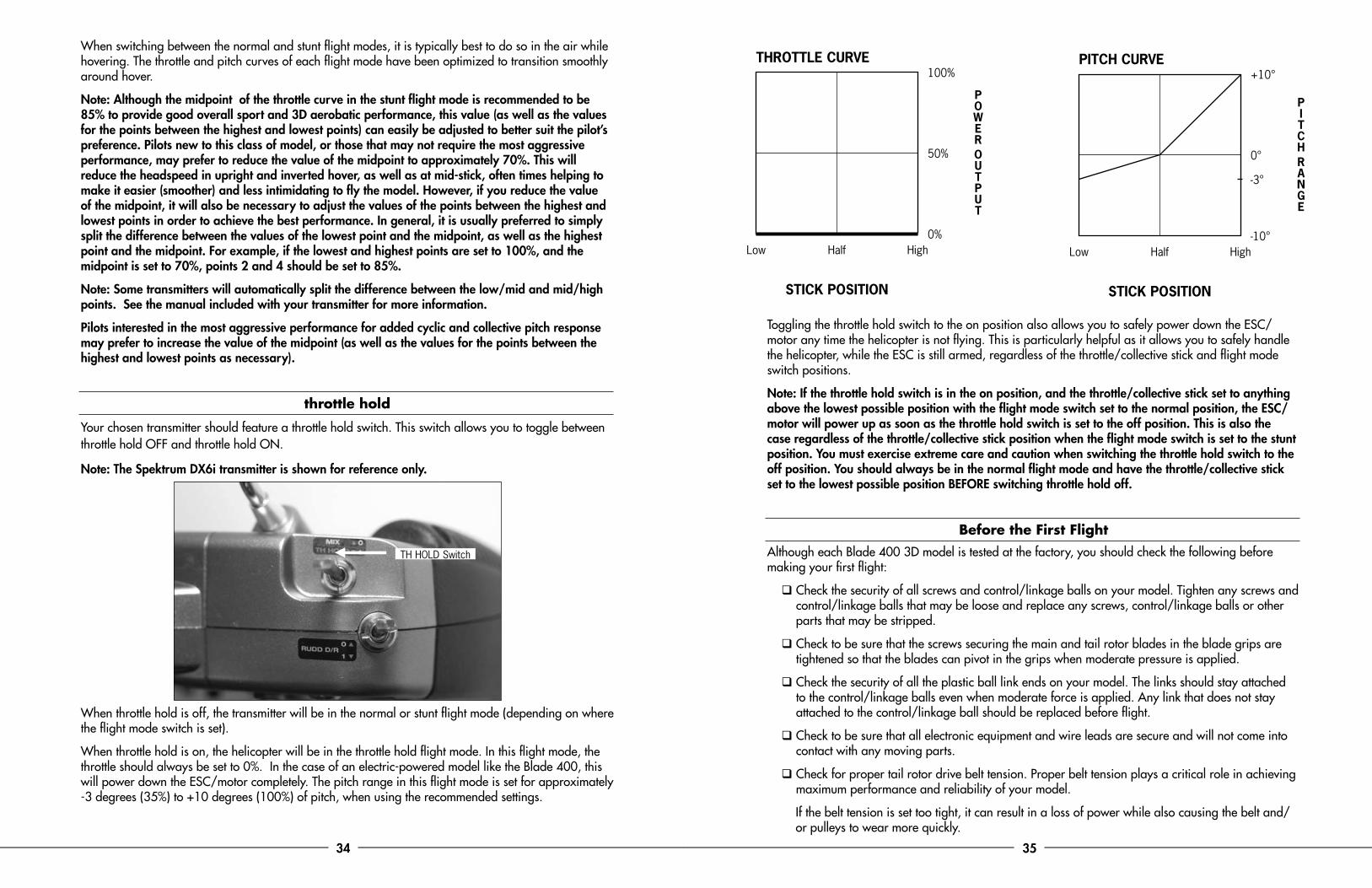
In the normal flight mode (when using the recommended settings), the throttle curve is linear from 0% to 100%, with a pitch range of approximately -3 degrees (35%) to +10 degrees (100%). This is the preferred flight mode for general hovering and basic (non-aerobatic) flight.
In the idle up/stunt flight mode (when using the recommended settings), the throttle curve is V shaped from 100% to 100% with 85% throttle at mid-stick, with a pitch range of -10 (0%) to +10 degrees (100%). This is the preferred flight mode for most forward/backward, aerobatic and 3D flying.
Note: When in the idle up/stunt flight mode, even with the throttle stick pulled all the way down to its lowest possible position, the motor and rotor blades will continue to spin. You must use the normal flight mode (or throttle hold) to safely power down the motor and rotor blades. For added safety, the ESC will not arm if the flight battery is plugged in and the flight mode switch is set to the stunt position.
Aileron Trim
Helicopter Moves Left
Helicopter Moves Right
THROTTLE CURVE
STICK POSITION
Low Half High
100%
50%
85%
0%
PITCH CURVE
STICK POSITION
Low Half High
+10°
0°
-10°
PITCH CURVE
STICK POSITION
Low Half High
+10°
0°
-10°
-3°
THROTTLE CURVE
STICK POSITION
Low Half High
100%
50%
0%
34 35
When switching between the normal and stunt flight modes, it is typically best to do so in the air while hovering. The throttle and pitch curves of each flight mode have been optimized to transition smoothly around hover.
Note: Although the midpoint of the throttle curve in the stunt flight mode is recommended to be 85% to provide good overall sport and 3D aerobatic performance, this value (as well as the values for the points between the highest and lowest points) can easily be adjusted to better suit the pilot’s preference. Pilots new to this class of model, or those that may not require the most aggressive performance, may prefer to reduce the value of the midpoint to approximately 70%. This will reduce the headspeed in upright and inverted hover, as well as at mid-stick, often times helping to make it easier (smoother) and less intimidating to fly the model. However, if you reduce the value of the midpoint, it will also be necessary to adjust the values of the points between the highest and lowest points in order to achieve the best performance. In general, it is usually preferred to simply split the difference between the values of the lowest point and the midpoint, as well as the highest point and the midpoint. For example, if the lowest and highest points are set to 100%, and the midpoint is set to 70%, points 2 and 4 should be set to 85%.
Note: Some transmitters will automatically split the difference between the low/mid and mid/high points. See the manual included with your transmitter for more information.
Pilots interested in the most aggressive performance for added cyclic and collective pitch response may prefer to increase the value of the midpoint (as well as the values for the points between the highest and lowest points as necessary).
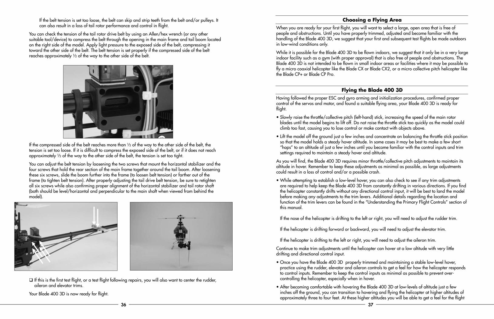
throttle hold
Your chosen transmitter should feature a throttle hold switch. This switch allows you to toggle between throttle hold OFF and throttle hold ON.
Note: The Spektrum DX6i transmitter is shown for reference only.
When throttle hold is off, the transmitter will be in the normal or stunt flight mode (depending on where the flight mode switch is set).
When throttle hold is on, the helicopter will be in the throttle hold flight mode. In this flight mode, the throttle should always be set to 0%. In the case of an electric-powered model like the Blade 400, this will power down the ESC/motor completely. The pitch range in this flight mode is set for approximately -3 degrees (35%) to +10 degrees (100%) of pitch, when using the recommended settings.
Toggling the throttle hold switch to the on position also allows you to safely power down the ESC/motor any time the helicopter is not flying. This is particularly helpful as it allows you to safely handle the helicopter, while the ESC is still armed, regardless of the throttle/collective stick and flight mode switch positions.
Note: If the throttle hold switch is in the on position, and the throttle/collective stick set to anything above the lowest possible position with the flight mode switch set to the normal position, the ESC/motor will power up as soon as the throttle hold switch is set to the off position. This is also the case regardless of the throttle/collective stick position when the flight mode switch is set to the stunt position. You must exercise extreme care and caution when switching the throttle hold switch to the off position. You should always be in the normal flight mode and have the throttle/collective stick set to the lowest possible position BEFORE switching throttle hold off.
Before the First FlightAlthough each Blade 400 3D model is tested at the factory, you should check the following before making your first flight:
q Check the security of all screws and control/linkage balls on your model. Tighten any screws and control/linkage balls that may be loose and replace any screws, control/linkage balls or other parts that may be stripped.
q Check to be sure that the screws securing the main and tail rotor blades in the blade grips are tightened so that the blades can pivot in the grips when moderate pressure is applied.
q Check the security of all the plastic ball link ends on your model. The links should stay attached to the control/linkage balls even when moderate force is applied. Any link that does not stay attached to the control/linkage ball should be replaced before flight.
q Check to be sure that all electronic equipment and wire leads are secure and will not come into contact with any moving parts.
q Check for proper tail rotor drive belt tension. Proper belt tension plays a critical role in achieving maximum performance and reliability of your model.
If the belt tension is set too tight, it can result in a loss of power while also causing the belt and/or pulleys to wear more quickly.
THROTTLE CURVE
STICK POSITION
Low Half High
100%
50%
0%
PITCH CURVE
STICK POSITION
Low Half High
+10°
0°
-10°
-3°
TH HOLD Switch
36 37
If the belt tension is set too loose, the belt can skip and strip teeth from the belt and/or pulleys. It can also result in a loss of tail rotor performance and control in flight.
You can check the tension of the tail rotor drive belt by using an Allen/hex wrench (or any other suitable tool/device) to compress the belt through the opening in the main frame and tail boom located on the right side of the model. Apply light pressure to the exposed side of the belt, compressing it toward the other side of the belt. The belt tension is set properly if the compressed side of the belt reaches approximately ½ of the way to the other side of the belt.
If the compressed side of the belt reaches more than ½ of the way to the other side of the belt, the tension is set too loose. If it is difficult to compress the exposed side of the belt, or if it does not reach approximately ½ of the way to the other side of the belt, the tension is set too tight.
You can adjust the belt tension by loosening the two screws that mount the horizontal stabilizer and the four screws that hold the rear section of the main frame together around the tail boom. After loosening these six screws, slide the boom further into the frame (to loosen belt tension) or farther out of the frame (to tighten belt tension). After properly adjusting the tail drive belt tension, be sure to retighten all six screws while also confirming proper alignment of the horizontal stabilizer and tail rotor shaft (both should be level/horizontal and perpendicular to the main shaft when viewed from behind the model).
q If this is the first test flight, or a test flight following repairs, you will also want to center the rudder, aileron and elevator trims.
Your Blade 400 3D is now ready for flight.
Choosing a Flying AreaWhen you are ready for your first flight, you will want to select a large, open area that is free of people and obstructions. Until you have properly trimmed, adjusted and become familiar with the handling of the Blade 400 3D, we suggest that your first and subsequent test flights be made outdoors in low-wind conditions only.
While it is possible for the Blade 400 3D to be flown indoors, we suggest that it only be in a very large indoor facility such as a gym (with proper approval) that is also free of people and obstructions. The Blade 400 3D is not intended to be flown in small indoor areas or facilities where it may be possible to fly a micro coaxial helicopter like the Blade CX or Blade CX2, or a micro collective pitch helicopter like the Blade CP+ or Blade CP Pro.
Flying the Blade 400 3DHaving followed the proper ESC and gyro arming and initialization procedures, confirmed proper control of the servos and motor, and found a suitable flying area, your Blade 400 3D is ready for flight.
• Slowly raise the throttle/collective pitch (left-hand) stick, increasing the speed of the main rotor blades until the model begins to lift off. Do not raise the throttle stick too quickly as the model could climb too fast, causing you to lose control or make contact with objects above.
• Lift the model off the ground just a few inches and concentrate on balancing the throttle stick position so that the model holds a steady hover altitude. In some cases it may be best to make a few short “hops” to an altitude of just a few inches until you become familiar with the control inputs and trim settings required to maintain a steady hover and altitude.
As you will find, the Blade 400 3D requires minor throttle/collective pitch adjustments to maintain its altitude in hover. Remember to keep these adjustments as minimal as possible, as large adjustments could result in a loss of control and/or a possible crash.
• While attempting to establish a low-level hover, you can also check to see if any trim adjustments are required to help keep the Blade 400 3D from constantly drifting in various directions. If you find the helicopter constantly drifts without any directional control input, it will be best to land the model before making any adjustments to the trim levers. Additional details regarding the location and function of the trim levers can be found in the “Understanding the Primary Flight Controls” section of this manual. If the nose of the helicopter is drifting to the left or right, you will need to adjust the rudder trim. If the helicopter is drifting forward or backward, you will need to adjust the elevator trim. If the helicopter is drifting to the left or right, you will need to adjust the aileron trim.
Continue to make trim adjustments until the helicopter can hover at a low altitude with very little drifting and directional control input.
• Once you have the Blade 400 3D properly trimmed and maintaining a stable low-level hover, practice using the rudder, elevator and aileron controls to get a feel for how the helicopter responds to control inputs. Remember to keep the control inputs as minimal as possible to prevent over-controlling the helicopter, especially when in hover.
• After becoming comfortable with hovering the Blade 400 3D at low-levels of altitude just a few inches off the ground, you can transition to hovering and flying the helicopter at higher altitudes of approximately three to four feet. At these higher altitudes you will be able to get a feel for the flight
38 39
characteristics of the Blade 400 3D when it is flying out of “ground effect.”
• If at any time during flight you feel like the helicopter is drifiting out of control, it is best to return all controls to neutral and to lower the throttle stick completely or activate throttle hold. This will help reduce the amount of damage that may be caused in the event of a crash.
• In the unfortunate event of a crash or rotor blade strIke, no matter how mInor or major, you must lower the throttle (left-hand) stIck to the lowest possIble posItIon (when In the normal flIght mode only) as quIckly as possIble to prevent damage to the esc. you can also actIvate throttle hold In any flIght mode, regardless of throttle stIck posItIon.
Failure to lower the throttle stick to the lowest possible position (in the Normal Flight mode only) or to activate throttle hold (in any flight mode) in the event of a crash could result in damage to the ESC.
While the ESC is readily capable of handling all in-flight power loads, and even brief momentary bursts beyond these typical loads, it can be damaged if an excessive amount of current is pulled through it for an extended period of time. This period of time may vary depending on conditions, so it is best to keep any momentary overloads as short as possible in order to prevent damage to the ESC.
Note: Crash damage is not covered under warranty.
• It is extremely important when hovering and flying the Blade 400 3D to be aware of the power level of the Li-Po battery pack. If at any time the helicopter begins to require more throttle than typical to maintain hover or flight or has lost significant power, you must land the helicopter IMMEDIATELY to prevent a sudden loss in power that could result in a crash.
Main Rotor Blade Tracking AdjustmentCaution: Be sure to maintain a safe distance from the helicopter (10–15 feet) when tracking the main rotor blades.
Blade tracking is a critical element to the flight performance of just about any helicopter, including the Blade 400 3D. Main rotor blades that are out of track may cause vibration, instability, and loss of power due to increased drag. Although the main rotor blades of each Blade 400 3D model are tracked at the factory, minor adjustments to blade tracking may be required after blade changes, linkage adjustments or repairs.
To check main rotor blade tracking and make any required adjustments, please note the following tips:
• Before proceeding with the test flight of a new model, or any model to which changes or repairs have been made, be certain that the main rotor blades have been properly installed and secured. The main rotor blade mounting bolts should be tightened so the blades can pivot in the blade grip when moderate pressure is applied. Never allow the main rotor blades to swing freely in their grips.
• After powering the model on and allowing the ESC and gyro to properly arm and initialize, bring the main rotor blades of your Blade 400 3D up to speed. You can check the blade tracking either on the ground or in the air at approximately eye level. It might be a good idea to have an assistant on hand to help sight the blades. Again, be certain to maintain a safe distance of 10–15 feet from the helicopter when checking the tracking of the main rotor blades.
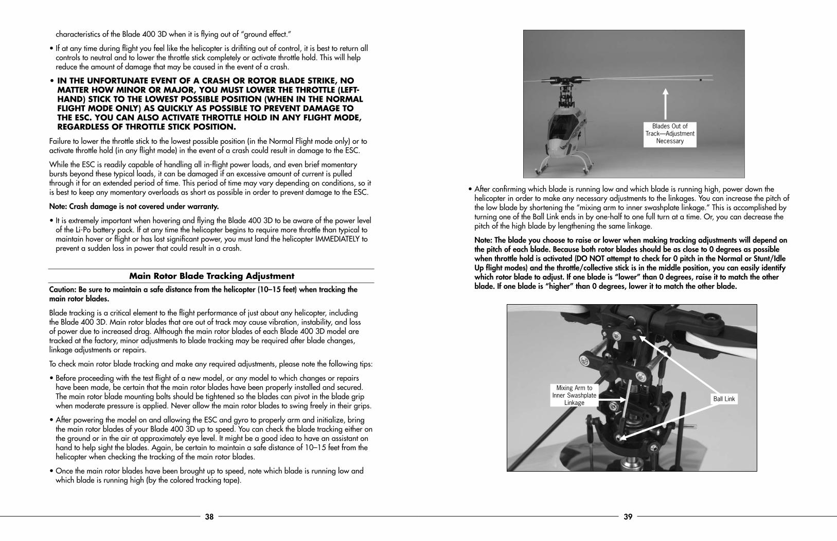
• Once the main rotor blades have been brought up to speed, note which blade is running low and which blade is running high (by the colored tracking tape).
• After confirming which blade is running low and which blade is running high, power down the helicopter in order to make any necessary adjustments to the linkages. You can increase the pitch of the low blade by shortening the “mixing arm to inner swashplate linkage.” This is accomplished by turning one of the Ball Link ends in by one-half to one full turn at a time. Or, you can decrease the pitch of the high blade by lengthening the same linkage.
Note: The blade you choose to raise or lower when making tracking adjustments will depend on the pitch of each blade. Because both rotor blades should be as close to 0 degrees as possible when throttle hold is activated (DO NOT attempt to check for 0 pitch in the Normal or Stunt/Idle Up flight modes) and the throttle/collective stick is in the middle position, you can easily identify which rotor blade to adjust. If one blade is “lower” than 0 degrees, raise it to match the other blade. If one blade is “higher” than 0 degrees, lower it to match the other blade.
Mixing Arm to Inner Swashplate
Linkage Ball Link
Blades Out of Track —Adjustment
Necessary
40 41
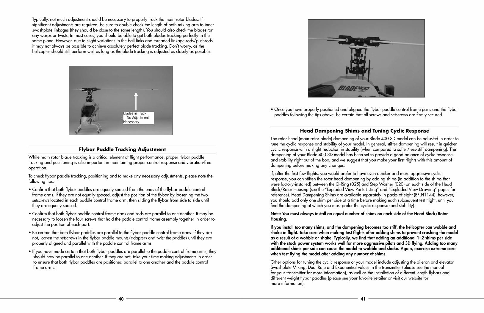
Typically, not much adjustment should be necessary to properly track the main rotor blades. If significant adjustments are required, be sure to double-check the length of both mixing arm to inner swashplate linkages (they should be close to the same length). You should also check the blades for any warps or twists. In most cases, you should be able to get both blades tracking perfectly in the same plane. However, due to slight variations in the ball links and threaded linkage rods/pushrods it may not always be possible to achieve absolutely perfect blade tracking. Don’t worry, as the helicopter should still perform well as long as the blade tracking is adjusted as closely as possible.
Flybar Paddle Tracking AdjustmentWhile main rotor blade tracking is a critical element of flight performance, proper flybar paddle tracking and positioning is also important in maintaining proper control response and vibration-free operation.
To check flybar paddle tracking, positioning and to make any necessary adjustments, please note the following tips:
• Confirm that both flybar paddles are equally spaced from the ends of the flybar paddle control frame arms. If they are not equally spaced, adjust the position of the flybar by loosening the two setscrews located in each paddle control frame arm, then sliding the flybar from side to side until they are equally spaced.
• Confirm that both flybar paddle control frame arms and rods are parallel to one another. It may be necessary to loosen the four screws that hold the paddle control frame assembly together in order to adjust the position of each part.
• Be certain that both flybar paddles are parallel to the flybar paddle control frame arms. If they are not, loosen the setscrews in the flybar paddle mounts/adapters and twist the paddles until they are properly aligned and parallel with the paddle control frame arms.
• I f you have made certain that both flybar paddles are parallel to the paddle control frame arms, they should now be parallel to one another. If they are not, take your time making adjustments in order to ensure that both flybar paddles are positioned parallel to one another and the paddle control frame arms.
• Once you have properly positioned and aligned the flybar paddle control frame parts and the flybar paddles following the tips above, be certain that all screws and setscrews are firmly secured.
Head Dampening Shims and Tuning Cyclic ResponseThe rotor head (main rotor blade) dampening of your Blade 400 3D model can be adjusted in order to tune the cyclic response and stability of your model. In general, stiffer dampening will result in quicker cyclic response with a slight reduction in stability (when compared to softer/less-stiff dampening). The dampening of your Blade 400 3D model has been set to provide a good balance of cyclic response and stability right out of the box, and we suggest that you make your first flights with this amount of dampening before making any changes.
If, after the first few flights, you would prefer to have even quicker and more aggressive cyclic response, you can stiffen the rotor head dampening by adding shims (in addition to the shims that were factory-installed) between the O-Ring (025) and Step Washer (020) on each side of the Head Block/Rotor Housing (see the “Exploded View Parts Listing” and “Exploded View Drawing” pages for reference). Head Dampening Shims are available separately in packs of eight (EFLH1144), however, you should add only one shim per side at a time before making each subsequent test flight, until you find the dampening at which you most prefer the cyclic response (and stability).
Note: You must always install an equal number of shims on each side of the Head Block/Rotor Housing.
If you install too many shims, and the dampening becomes too stiff, the helicopter can wobble and shake in flight. Take care when making test flights after adding shims to prevent crashing the model as a result of a wobble or shake. Typically, we find that adding an additional 1–2 shims per side with the stock power system works well for more aggressive pilots and 3D flying. Adding too many additional shims per side can cause the model to wobble and shake. Again, exercise extreme care when test flying the model after adding any number of shims.
Other options for tuning the cyclic response of your model include adjusting the aileron and elevator Swashplate Mixing, Dual Rate and Exponential values in the transmitter (please see the manual for your transmitter for more information), as well as the installation of different length flybars and different weight flybar paddles (please see your favorite retailer or visit our website for more information).
Blades in Track —No Adjustment Necessary
42 43
Recommended MaintenanceRoutine maintenance is necessary to keep your Blade 400 3D in optimal and safe flying condition. Some of the most important things to check routinely include:
• Ball Links Before each flying session, check to see that the plastic ball link ends are secure, but not tight (binding), on the linkage/control balls. The plastic ball links can wear over time, and if they become too loose on the control balls, they can separate from the ball in flight and cause a crash. Be sure to replace any worn ball links before they fail. Also, any ball links that are tight (binding) on the linkage/control balls can be loosened by carefully squeezing the sides of the link with a pair of pliers. However, exercise extreme care when “sizing” the ball links as it is possible to loosen them too much for safe use.
• Bearings The one-way bearing in the main drive gear should be cleaned using isopropyl alcohol or electric motor spray, then lubed with lightweight oil, approximately every 80 to 100 flights. All other bearings typically exhibit very long life and normally only need to be replaced if they ever become notchy (sticky in places when turning) or draggy.
• Oiling It’s important to apply a small amount of lightweight oil (like TRI4026) to any areas where a bushing may ride on a shaft, especially after replacing any of the parts with new ones after a crash. Some areas to oil include where the washout base bushing and swashplate control ball ride on the main shaft, and where the tail rotor control pitch slider bushing rides on the tail rotor shaft.
• O-Ring Head Dampeners The O-ring dampeners in the head block will periodically wear and lose their elasticity. Worn O-rings can cause main rotor blade tracking problems as well as stability and control response issues. If you begin having trouble with the blades going in and out of track during flight, or if the helicopter feels loose and “mushy” during flight, it is likely time to replace the O-ring dampeners. The O-ring dampeners can wear out in approximately 30 to 60 flights depending on how the model is flown. Also, when replacing the O-ring dampeners, it’s important to lubricate them with a silicon-based grease to prevent friction.
• Tail Rotor Drive Belt It’s typical for the tail drive belt to stretch slightly over the first few flights. When new, frequently check and adjust the belt tension as required. After approximately 20 to 40 flights, the belt elasticity will stabilize, requiring little to no additional tension adjustment.
2008 official ama national model aircraft safety codeGENERAL 1. A model aircraft shall be defined as a non-human-carrying device capable of sustained flight in the atmosphere. It shall not exceed limitations established in this code and is intended to be used exclusively for recreational or competition activity. 2. The maximum takeoff weight of a model aircraft, including fuel, is 55 pounds, except for those flown under the AMA Experimental Aircraft Rules. 3. I will abide by this Safety Code and all rules established for the flying site I use. I will not willfully fly my model aircraft in a reckless and/or dangerous manner. 4. I will not fly my model aircraft in sanctioned events, air shows, or model demonstrations until it has been proven airworthy. 5. I will not fly my model aircraft higher than approximately 400 feet above ground level, when within three (3) miles of an airport without notifying the airport operator. I will yield the right-of-way and avoid flying in the proximity of full-scale aircraft, utilizing a spotter when appropriate. 6. I will not fly my model aircraft unless it is identified with my name and address, or AMA number, inside or affixed to the outside of the model aircraft. This does not apply to model aircraft flown indoors. 7. I will not operate model aircraft with metal-blade propellers or with gaseous boosts (other than air), nor will I operate model aircraft with fuels containing tetranitromethane or hydrazine. 8. I will not operate model aircraft carrying pyrotechnic devices which explode burn, or propel a projectile of any kind. Exceptions include Free Flight fuses or devices that burn producing smoke and are securely attached to the model aircraft during flight. Rocket motors up to a G-series size may be used, provided they remain firmly attached to the model aircraft during flight. Model rockets may be flown in accordance with the National Model Rocketry Safety Code; however, they may not be launched from model aircraft. Officially designated AMAAir Show Teams (AST) are authorized to use devices and practices as defined within the Air Show Advisory Committee Document. 9. I will not operate my model aircraft while under the influence of alcohol or within eight (8) hours of having consumed alcohol. 10. I will not operate my model aircraft while using any drug which could adversely affect my ability to safely control my model aircraft. 11. Children under six (6) years old are only allowed on a flightline or in a flight area as a pilot or while under flight instruction. 12. When and where required by rule, helmets must be properly worn and fastened. They must be OSHA, DOT, ANSI, SNELL or NOCSAE approved or comply with comparable standards.
RADIO CONTROL 1. All model flying shall be conducted in a manner to avoid flying or flight over unprotected people. 2. I will have completed a successful radio equipment ground-range check before the first flight of a new or repaired model aircraft. 3. I will not fly my model aircraft in the presence of spectators until I become a proficient flier, unless I am assisted by an experienced pilot. 4. At all flying sites a line must be established, in front of which all flying takes place. Only personnel associated with flying the model aircraft are allowed at or in front of the line. In the case of air shows, a straight line for demonstrations must be established. An area away from the line must be maintained for spectators. Intentional flying behind the line is prohibited. 5. I will operate my model aircraft using only radio-control frequencies currently allowed by the Federal Communications Commission (FCC). Only individuals properly licensed by the FCC are authorized to operate equipment on Amateur Band frequencies. 6. I will not knowingly operate my model aircraft within three (3) miles of any preexisting flying site without a frequency-management agreement. A frequency-management agreement may be an allocation of frequencies for each site, a day-use agreement between sites, or testing which determines that no interference exists. A frequency-management agreement may exist between two or more AMA chartered clubs, AMA clubs and individual AMA members, or individual AMA members. Frequency-management agreements, including an interference test report if the agreement indicates no interference exists, will be signed by all parties and copies provided to AMA Headquarters. 7. With the exception of events flown under official AMA rules, no powered model may be flown outdoors closer than 25 feet to any individual, except for the pilot and located at the flightline. 8. Under no circumstances may a pilot or other person touch a model aircraft in flight while it is still under power, except to divert it from striking an individual. 9. Radio-controlled night flying is limited to low-performance model aircraft (less than 100 mph). The model aircraft must be equipped with a lighting system which clearly defines the aircraft’s attitude and direction at all times. 10. The operator of a radio-controlled model aircraft shall control it during the entire flight, maintaining visual contact without enhancement other than by corrective lenses that are prescribed for the pilot. No model aircraft shall be equipped with devices which allow it to be flown to a selected location which is beyond the visual range of the pilot.
FREE FLIGHT 1. I will not launch my model aircraft unless I am at least 100 feet downwind of spectators and automobile parking. 2. I will not fly my model aircraft unless the launch area is clear of all individuals except my mechanic, officials, and other fliers. 3. I will use an effective device to extinguish any fuse on the model aircraft after the fuse has completed its function.
CONTROL LINE 1. I will subject my complete control system (including the safety thong where applicable) to an inspection and pull test prior to flying. The pull test will be in accordance with the current for the applicable model aircraft category. Model aircraft not fitting a specific category shall use those pull test requirements as indicated for Control Line Precision Aerobatics. 2. I will ensure that my flying area is clear of all utility wires or poles and I will not fly a model aircraft closer than 50 feet to any above-ground electric utility lines. 3. I will ensure that my flying area is clear of all nonessential participants and spectators before permitting my engine to be started.
PARK FLYER SAFE OPERATING RECOMMENDATIONS - Inspect your model before every flight to make certain it is airworthy. - Be aware of any other radio frequency user who may present an interference problem. - Always be courteous and respectful of other users of your selected flight area. - Choose an area clear of obstacles and large enough to safely accommodate your flying activity. - Make certain this area is clear of friends and spectators prior to launching your aircraft. - Be aware of other activities in the vicinity of your flight path that could cause potential conflict. - Carefully plan your flight path prior to launch. - Abide by any and all established AMA National Model Aircraft Safety Code.
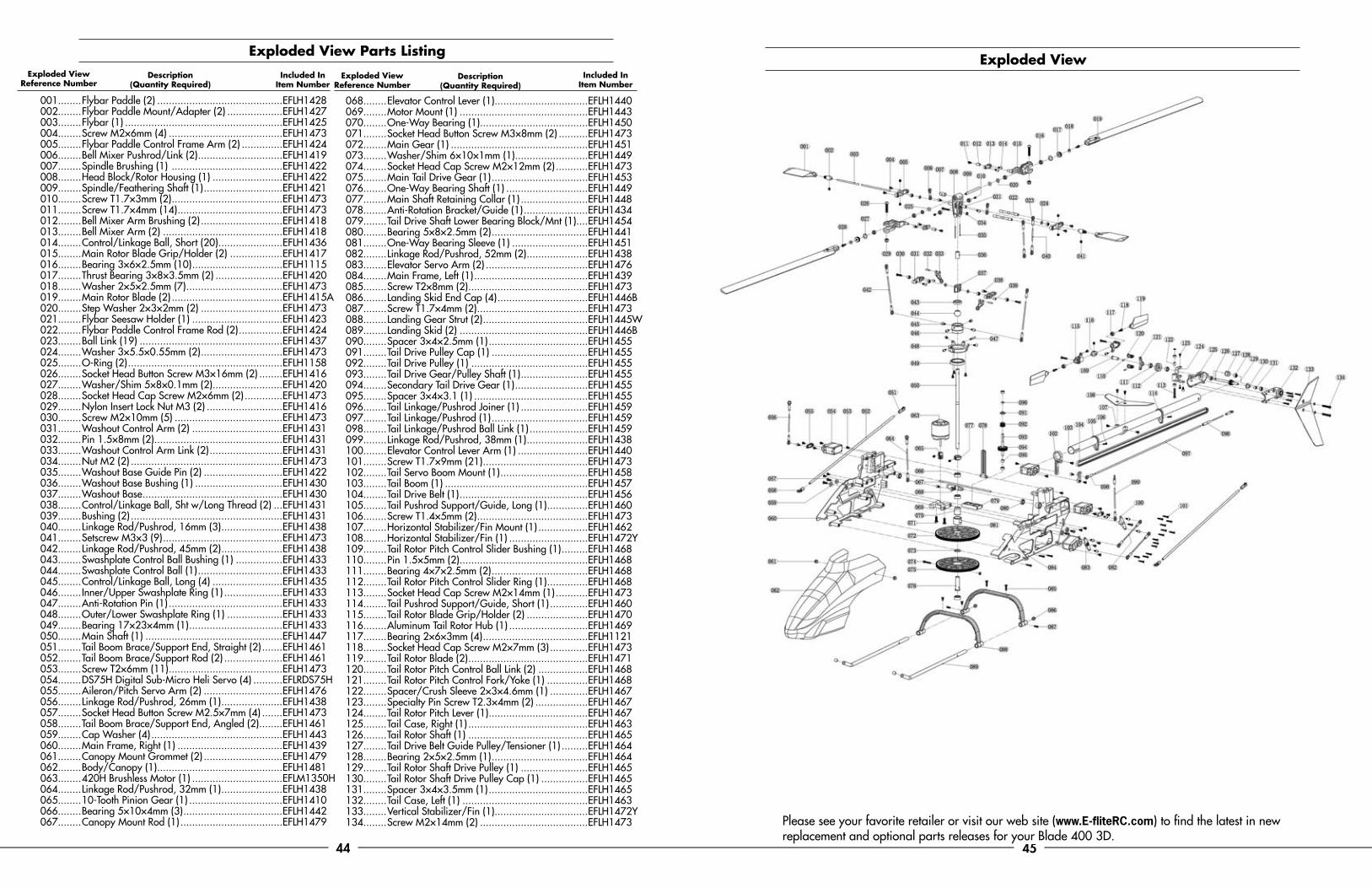
44 45
exploded view
Please see your favorite retailer or visit our web site (www.E-fliteRC.com) to find the latest in new replacement and optional parts releases for your Blade 400 3D.
001........Flybar Paddle (2) ...........................................EFLH1428002........Flybar Paddle Mount/Adapter (2) ...................EFLH1427003........Flybar (1) ......................................................EFLH1425004........Screw M2×6mm (4) .......................................EFLH1473005........Flybar Paddle Control Frame Arm (2) ..............EFLH1424006........Bell Mixer Pushrod/Link (2) .............................EFLH1419007........Spindle Brushing (1) ......................................EFLH1422008........Head Block/Rotor Housing (1) ........................EFLH1422009........Spindle/Feathering Shaft (1) ...........................EFLH1421010........Screw T1.7×3mm (2) ......................................EFLH1473011........Screw T1.7×4mm (14) ....................................EFLH1473012........Bell Mixer Arm Brushing (2) ............................EFLH1418013........Bell Mixer Arm (2) .........................................EFLH1418014........Control/Linkage Ball, Short (20) ......................EFLH1436015........Main Rotor Blade Grip/Holder (2) ..................EFLH1417016........Bearing 3×6×2.5mm (10) ...............................EFLH1115017........Thrust Bearing 3×8×3.5mm (2) .......................EFLH1420018........Washer 2×5×2.5mm (7) .................................EFLH1473019........Main Rotor Blade (2) ......................................EFLH1415A020........Step Washer 2×3×2mm (2) ............................EFLH1473021........Flybar Seesaw Holder (1) ...............................EFLH1423022........Flybar Paddle Control Frame Rod (2) ...............EFLH1424023........Ball Link (19) .................................................EFLH1437024........Washer 3×5.5×0.55mm (2) ............................EFLH1473025........O-Ring (2) .....................................................EFLH1158026........Socket Head Button Screw M3×16mm (2) ........EFLH1416027........Washer/Shim 5×8×0.1mm (2) ........................EFLH1420028........Socket Head Cap Screw M2×6mm (2) .............EFLH1473029........Nylon Insert Lock Nut M3 (2) ..........................EFLH1416030........Screw M2×10mm (5) .....................................EFLH1473031........Washout Control Arm (2) ...............................EFLH1431032........Pin 1.5×8mm (2) ............................................EFLH1431033........Washout Control Arm Link (2) .........................EFLH1431034........Nut M2 (2) ....................................................EFLH1473035........Washout Base Guide Pin (2) ...........................EFLH1422036........Washout Base Bushing (1) ..............................EFLH1430037........Washout Base ................................................EFLH1430038........Control/Linkage Ball, Sht w/Long Thread (2) ...EFLH1431039........Bushing (2) ....................................................EFLH1431040........Linkage Rod/Pushrod, 16mm (3) .....................EFLH1438041........Setscrew M3×3 (9) .........................................EFLH1473042........Linkage Rod/Pushrod, 45mm (2) .....................EFLH1438043........Swashplate Control Ball Bushing (1) ................EFLH1433044........Swashplate Control Ball (1) .............................EFLH1433045........Control/Linkage Ball, Long (4) ........................EFLH1435046........Inner/Upper Swashplate Ring (1) ....................EFLH1433047........Anti-Rotation Pin (1) .......................................EFLH1433048........Outer/Lower Swashplate Ring (1) ...................EFLH1433049........Bearing 17×23×4mm (1) ................................EFLH1433050........Main Shaft (1) ...............................................EFLH1447051........Tail Boom Brace/Support End, Straight (2) .......EFLH1461052........Tail Boom Brace/Support Rod (2) ....................EFLH1461053........Screw T2×6mm (11) .......................................EFLH1473054........DS75H Digital Sub-Micro Heli Servo (4) ..........EFLRDS75H055........Aileron/Pitch Servo Arm (2) ...........................EFLH1476056........Linkage Rod/Pushrod, 26mm (1) .....................EFLH1438057........Socket Head Button Screw M2.5×7mm (4) .......EFLH1473058........Tail Boom Brace/Support End, Angled (2) ........EFLH1461059........Cap Washer (4) .............................................EFLH1443060........Main Frame, Right (1) ....................................EFLH1439061........Canopy Mount Grommet (2) ...........................EFLH1479062........Body/Canopy (1) ...........................................EFLH1481063........420H Brushless Motor (1) ...............................EFLM1350H064........Linkage Rod/Pushrod, 32mm (1) .....................EFLH1438065........10-Tooth Pinion Gear (1) ................................EFLH1410066........Bearing 5×10×4mm (3) ..................................EFLH1442067........Canopy Mount Rod (1) ...................................EFLH1479
exploded view parts listing
068........Elevator Control Lever (1) ................................EFLH1440069........Motor Mount (1) ............................................EFLH1443070........One-Way Bearing (1) .....................................EFLH1450071........Socket Head Button Screw M3×8mm (2) ..........EFLH1473072........Main Gear (1) ...............................................EFLH1451073........Washer/Shim 6×10×1mm (1) .........................EFLH1449074........Socket Head Cap Screw M2×12mm (2) ...........EFLH1473075........Main Tail Drive Gear (1) .................................EFLH1453076........One-Way Bearing Shaft (1) ............................EFLH1449077........Main Shaft Retaining Collar (1) .......................EFLH1448078........Anti-Rotation Bracket/Guide (1) ......................EFLH1434079........Tail Drive Shaft Lower Bearing Block/Mnt (1)....EFLH1454080........Bearing 5×8×2.5mm (2) .................................EFLH1441081........One-Way Bearing Sleeve (1) ..........................EFLH1451082........Linkage Rod/Pushrod, 52mm (2) .....................EFLH1438083........Elevator Servo Arm (2) ...................................EFLH1476084........Main Frame, Left (1) .......................................EFLH1439085........Screw T2×8mm (2) .........................................EFLH1473086........Landing Skid End Cap (4) ...............................EFLH1446B087........Screw T1.7×4mm (2) ......................................EFLH1473088........Landing Gear Strut (2) ....................................EFLH1445W089........Landing Skid (2) ............................................EFLH1446B090........Spacer 3×4×2.5mm (1) ..................................EFLH1455091........Tail Drive Pulley Cap (1) .................................EFLH1455092........Tail Drive Pulley (1) ........................................EFLH1455093........Tail Drive Gear/Pulley Shaft (1) .......................EFLH1455094........Secondary Tail Drive Gear (1) .........................EFLH1455095........Spacer 3×4×3.1 (1) .......................................EFLH1455096........Tail Linkage/Pushrod Joiner (1) .......................EFLH1459097........Tail Linkage/Pushrod (1) .................................EFLH1459098........Tail Linkage/Pushrod Ball Link (1) ....................EFLH1459099........Linkage Rod/Pushrod, 38mm (1) .....................EFLH1438100........Elevator Control Lever Arm (1) ........................EFLH1440101........Screw T1.7×9mm (21) ....................................EFLH1473102........Tail Servo Boom Mount (1) ..............................EFLH1458103........Tail Boom (1) .................................................EFLH1457104........Tail Drive Belt (1) ............................................EFLH1456105........Tail Pushrod Support/Guide, Long (1) ..............EFLH1460106........Screw T1.4×5mm (2) ......................................EFLH1473107........Horizontal Stabilizer/Fin Mount (1) .................EFLH1462108........Horizontal Stabilizer/Fin (1) ...........................EFLH1472Y109........Tail Rotor Pitch Control Slider Bushing (1) .........EFLH1468110........Pin 1.5×5mm (2) ............................................EFLH1468111........Bearing 4×7×2.5mm (2) .................................EFLH1468112........Tail Rotor Pitch Control Slider Ring (1) ..............EFLH1468113........Socket Head Cap Screw M2×14mm (1) ...........EFLH1473114........Tail Pushrod Support/Guide, Short (1) .............EFLH1460115........Tail Rotor Blade Grip/Holder (2) .....................EFLH1470116........Aluminum Tail Rotor Hub (1) ...........................EFLH1469117........Bearing 2×6×3mm (4) ....................................EFLH1121118........Socket Head Cap Screw M2×7mm (3) .............EFLH1473119........Tail Rotor Blade (2) .........................................EFLH1471120........Tail Rotor Pitch Control Ball Link (2) .................EFLH1468121........Tail Rotor Pitch Control Fork/Yoke (1) ..............EFLH1468122........Spacer/Crush Sleeve 2×3×4.6mm (1) .............EFLH1467123........Specialty Pin Screw T2.3×4mm (2) ..................EFLH1467124........Tail Rotor Pitch Lever (1) ..................................EFLH1467125........Tail Case, Right (1) .........................................EFLH1463126........Tail Rotor Shaft (1) .........................................EFLH1465127........Tail Drive Belt Guide Pulley/Tensioner (1) .........EFLH1464128........Bearing 2×5×2.5mm (1) .................................EFLH1464129........Tail Rotor Shaft Drive Pulley (1) .......................EFLH1465130........Tail Rotor Shaft Drive Pulley Cap (1) ................EFLH1465131........Spacer 3×4×3.5mm (1) ..................................EFLH1465132........Tail Case, Left (1) ...........................................EFLH1463133........Vertical Stabilizer/Fin (1) ................................EFLH1472Y134........Screw M2×14mm (2) .....................................EFLH1473
exploded view Reference Number
Description (Quantity Required)
Description (Quantity Required)
Included In Item Number
Included In Item Number
exploded view Reference Number

46 47
Please see your favorite retailer or visit our web site (www.E-fliteRC.com) to find the latest in new replacement and option parts releases for your Blade 400 3D.
Please see your favorite retailer or visit our web site (www.E-fliteRC.com) to find the latest in new replacement and option parts releases for your Blade 400 3D.
EFLA325H ........ 25-Amp Helicopter Brushless ESCEFLM1350H ..... Brushless 420 Helicopter Motor, 3800KvEFLH1001 ........ Mini Helicopter Main Blade Holder: B400EFLH1401 ........ Blade 400 3D ARF Replacement AirframeEFLH1410 ........ Pinion Gear, 10T 0.5M: B400EFLH1415A ...... 325mm Wood Main Rotor Blade Set, White: B400EFLH1416 ........ Main Rotor Blade Mounting Screw and Nut Set: B400EFLH1417 ........ Main Rotor Blade Grip/Holder Set: B400EFLH1418 ........ Bell Mixer Arm and Pushrod/Link Set: B400EFLH1419 ........ Bell Mixer Pushrod/Link (2): B400EFLH1420 ........ Thrust Bearing 3x8x3.5mm (2): B400EFLH1421 ........ Spindle/Feathering Shaft (2): B400EFLH1422 ........ Head Block/Rotor Housing Set: B400EFLH1423 ........ Flybar Seesaw Holder Set: B400EFLH1424 ........ Flybar Paddle Control Frame Set: B400EFLH1425 ........ Flybar, 220mm (2): B400EFLH1427 ........ Flybar Paddle Mounts/Adapters: B400EFLH1428 ........ Flybar Paddle Set for Mounts/Adapters: B400EFLH1430 ........ Washout Base: B400EFLH1431 ........ Washout Control Arm and Link Set: B400EFLH1432 ........ Washout Control Arm Link Set: B400EFLH1433 ........ Aluminum and Composite Swashplate: B400EFLH1434 ........ Anti-Rotation Bracket/Guide: B400EFLH1435 ........ Control/Linkage Ball, Long (4): B400EFLH1436 ........ Control/Linkage Ball, Short (10): B400EFLH1437 ........ Ball Link Set (20): B400EFLH1438 ........ Linkage Rod/Pushrod Set: B400EFLH1439 ........ Main Frame Set: B400EFLH1440 ........ Elevator Control Lever Set: B400EFLH1441 ........ Bearing 5x8x2.5mm (2): B400EFLH1442 ........ Bearing 5x10x4mm (2): B400EFLH1443 ........ Aluminum Motor Mount Set: B400EFLH1444 ........ Hook and Loop Battery Strap: B400EFLH1445W ..... Landing Gear Strut Set, White: B400
EFLH1446B ....... Landing Gear Skid Set, Black: B400EFLH1447 ........ Main Shaft (2): B400EFLH1448 ........ Main Shaft Retaining Collar: B400EFLH1449 ........ One-Way Bearing Shaft and Shim Set: B400EFLH1450 ........ One-Way Bearing 6x10x12mm: B400EFLH1451 ........ Main Gear w/o One-Way Bearing: B400EFLH1452 ........ Main Gear w/One-Way Bearing: B400EFLH1453 ........ Main Tail Drive Gear: B400EFLH1454 ........ Tail Drive Shaft Lower Bearing Block/Mount: B400EFLH1455 ........ Tail Drive Gear/Pulley Assembly: B400EFLH1456 ........ Tail Drive Belt: B400EFLH1457 ........ Tail Boom (2): B400EFLH1458 ........ Tail Servo Boom Mount: B400EFLH1459 ........ Tail Linkage/Pushrod Set: B400EFLH1460 ........ Tail Pushrod Support/Guide Set: B400EFLH1461 ........ Tail Boom Brace/Support Set: B400EFLH1462 ........ Horizontal Stabilizer/Fin Mount: B400EFLH1463 ........ Tail Case Set: B400EFLH1464 ........ Tail Drive Belt Guide Pulley/Tensioner: B400EFLH1465 ........ Tail Rotor Shaft and Drive Pulley (2): B400EFLH1466 ........ Bearing 2x5x2.5mm (2): B400EFLH1467 ........ Tail Rotor Pitch Lever Set: B400EFLH1468 ........ Tail Rotor Pitch Control Slider Set: B400EFLH1469 ........ Aluminum Tail Rotor Hub Set: B400EFLH1470 ........ Tail Rotor Blade Grip/Holder Set: B400EFLH1471 ........ Tail Rotor Blade Set: B400EFLH1472Y ...... Stabilizer/Fin Set, Yellow: B400EFLH1473 ........ Complete Hardware Set: B400EFLH1474 ........ Mounting Accessories Set: B400EFLH1475 ........ Blade 400 3D PNP Electric Mini HelicopterEFLH1476 ........ Servo Arm Set, DS75: B400EFLH1479 ........ Canopy Mount Rod & Grommet Set: B400EFLH1481 ........ Body/Canopy, Tribal w/Decals: B400EFLH1482 ........ Decal Sheet, Tribal: B400
Replacement Parts List optional parts listEFLA229 ..............Adaptor Cables for THP Battery to EFL Balancer/ChargerEFLA261 ..............Micro/Mini Heli Tool Assortment, 6 pc EFLAEC301 ..........EC3 Device Connector, Male (2)EFLAEC302 ..........EC3 Battery Connector, Female (2)EFLAEC303 ..........EC3 Device & Battery Connector, Male/FemaleEFLAEC312 ..........EC3 Device Chrge Lead w/12” Wire & Jacks, 16GAEFLB18003S .........1800mAh 3S 11.1V 20C LiPo, 13GA EC3EFLC3115 ............3S 11.1V LiPo Balancing Charger, 1.8AEFLC4030 ............100-240V AC to 12V DC, 3.0 Amp Power SupplyEFLC505 ..............1-5 Cell LiPo Charger with BalancerEFLH1000 ............Micro/Mini Helicopter Pitch GaugeEFLH1144 ............Head Dampening Shim (8): BCP, BCPP, B400EFLH1409 ............Pinion Gear, 9T 0.5M: B400EFLH1411 ............Pinion Gear, 11T 0.5M: B400EFLH1415C ..........325mm Carbon Fiber Main Rotor Blade Set: B400EFLH1417A ..........Aluminum Main Rotor Blade Grip Set w/Arms: B400EFLH1422A ..........Aluminum Head Block/Rotor Housing Set: B400EFLH1424A ..........Aluminum Flybar Paddle Control Frame Arm Set: B400EFLH1429C ..........3D Flybar Paddle Set w/Weights, Carbon Fiber: B400EFLH1430A ..........Aluminum Washout Base: B400EFLH1431A ..........Aluminum Washout Control Arm Set: B400EFLH1433A ..........Aluminum Swashplate: B400EFLH1434A ..........Alum Anti-Rotation Bracket/Guide: B400EFLH1454A ..........Alum Tail Drive Shaft Lower Bearing Block: B400EFLH1455A ..........Alum Speed-Up Tail Drive Gear/Pulley AssyEFLH1457C ..........Tail Boom, Carbon Fiber: B400EFLH1458A ..........Aluminum Tail Servo Boom Mount: B400EFLH1461A ..........Tail Boom Brace/Sprt Set w/Alum Ends: B400EFLH1462A ..........Alum Horizontal Stabilizer/Fin Mount: B400EFLH1463A ..........Alum Tail Case Set: B400EFLH1465A ..........Tail Rotor Shaft and Alum Drive Pulley: B400EFLH1468A ..........Alum Tail Rotor Pitch Control Slider Set: B400EFLH1470A ..........Alum Tail Rotor Blade Grip Set w/Hub: B400EFLH1471C ..........Tail Rotor Blade Set, Carbon Fiber: B400EFLH1472B ...........Stabilizer/Fin Set, Blue: B400EFLH1472C ..........Stabilizer/Fin Set, Carbon Fiber: B400EFLH1472W .........Stabilizer/Fin Set, White: B400EFLH1480 ............Body/Canopy, White w/o DecalsEFLH1483 ............Body/Canopy, Flame w/Decals: B400EFLH1484 ............Decal Sheet, Flame: B400THP21003SPL ....... 2100mAh 3-Cell/3S 11.1V 15C Pro Lite LiPo, 16GATHP22003SXV ...... 2200mAh 3-Cell/3S 11.1V 25C eXtreme V2 LiPo, 13GATHP610 ................ TP610C 1–6-Cell LiPo 0.25-10A DC Charger w/Balancer THPH325CF ..........325mm Carbon Fiber Rotor Blade Set

Futaba is a registered trademark of Futaba Denshi Kogyo Kabushiki Kaisha Corporation of Japan. Spektrum is used with permission of Bachmann Industries Inc., Spektrum radios and accessories are exclusively available from Horizon Hobby, Inc.
DSM and DSM2 are trademarks or registered trademarks of Horizon Hobby.
13107
© 2008 Horizon Hobby, Inc. 4105 Fieldstone Road
Champaign, Illinois 61822 (877) 504-0233
www.E-fliteRC.com