Embed Size (px)
Citation preview
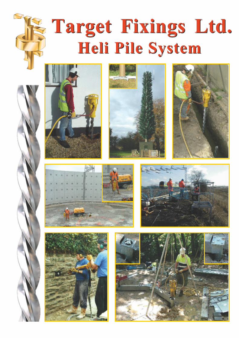
Target Fixings Ltd.Heli Pile System
Target Fixings Ltd.Heli Pile System

©Target Fixings 2008 Version 1.01
TARGET FIXINGS LTD
THE HELI PILE INFORMATION BROCHURE
CONTENTS
Section T i t l e
1 Introduction.
2 Pile Requirements.
3 Development of the Heli Pile.
4 Methods Compared.
5 Materials.
6 Installation Procedure.
7 Pile Capping/Connection Details.
8 Site Testing.
9 Load Carrying Capacity.
1 0 Uses.
1 1 Performance.
1 2 Pile and Beam Combination System.
1 3 Special Features.
1 4 Summary.
Annex T i t l e
A Comparison of Different Pile Types.
B Properties of LM25 (Al-Si7Mg0.5) Aluminium Casting Alloy.
C Installation Procedure for the Heli Pile.
D Heli Pile Standard Details.
E Typical Uses of the Heli Pile.
F Heli Pile Performance Guide.
Heli Pile is a registered Trade Mark of Target Fixings Limited.The Heli Pile is the subject of a Registered Design.
Target Fixings Limited,
Unit 6, Hungerford Trd. Est., Smitham Bridge road, Hungerford, Berks, RG17 0QP, United Kingdom
Tel : +44 (0) 1488 686 311 Fax : +44 (0) 1488 681 535
Web : www.targetfixings.com E-mail : [email protected]

©Target Fixings 2008 Page 1 Version 1.0
TARGET FIXINGS HELI PILE SYSTEM
1 . INTRODUCTION.
1.1. Although the Heli Pile is a relatively new product the concept of using a pile has beenaccepted for a long time. The new parts are the shape of the pile, the method ofinstallation and the method of determining its load carrying capacity.
1.2. Timber shafts driven into the ground have been used as a method of piling for many, manyyears. Venice is, of course, a tribute to the success of this method of gaining a goodfoundation. The life expectancy of timber piles is variable to say the least. It is arguablethat the principles of piling have not progressed a great deal since the very early days.Piles are dependent principally upon the frictional hold in the surrounding substrate andsecondly upon their end bearing for their overall load bearing capacity.
1.3. The overall size and the proportions of a pile need to be considered carefully at the designstage. The (a) mechanical strength, (b) rigidity under load, (c) surface extension and(d) surface disposition are important factors. If there is considerable ground disturbancecaused by the installation process the bearing capacity can be markedly reduced or eventotally destroyed.
2 . PILE REQUIREMENTS.
2.1. Mechanical Strength.
2.1.1 A foundation pile must have the mechanical strength to withstand any imposed loadsplaced upon it. The greatest considerations for this factor are the materials involved andthe cross-sectional area.
2.2. Rigidity .
2.2.1. Since the principal load to be reckoned with is vertical axial compression the rigidity ofthe pile is determined by its slenderness ratio. The slenderness ratio is determined bydividing the length of the pile by its radius. A shorter, fatter pile tends to be more rigidthan a longer thinner one.
2.3. Surface Extension.
2.3.1. The surface extension of the pile is an enabling property since it is a measure of theability to distribute the application of force over the affected underground. In otherwords the pile must have a substantial surface area in intimate contact with thesubstrate.
2.4. Surface Disposition.
2.4.1. The surface disposition of most forms of pile are all the same, i.e. vertical surfaces only.In order to enhance the value of the surface disposition it is possible to incline thevertical surfaces. The introduction of a helical surface is a further method of increasingsurface disposition.

©Target Fixings 2008 Page 2 Version 1.0
3 . DEVELOPMENT OF THE HELI PILE.
3.1. In about 1993 we were in discussions over the possibility of using the helical concept inpiling. We had determined a need for a quick and simple solution for a lightweight pilingsystem. Our initial work was confined to methods of employing our 10mm helicalsections and driving them in at angles into the ground to act as a "spreader" and thencasting a concrete cap on the top. This radical solution was soon found to be unacceptableto the engineering fraternity.
3.2. Since about 1995 we had been playing with the idea of a much larger and stiffer helicalsection that could be driven into the ground using lightweight machinery. This offered asolution to the classic problem of the corner of a property dropping due to the lack of asoakaway for the rainwater downpipe. The footings get washed away and the corner movesslightly. The old solution was to underpin, with all the disruption and mess involved, andthe added problem of creating a "hardspot". We now have the ability to Heli Pile and to useBar Flex masonry reinforcement to beam around the corner.
3.3. The concept for the Heli Pile was patented in January 1997 and was then furtherdeveloped with the aid of a DTI Smart Grant. Initial site testing was carried out with theassistance of the Engineering Department of the University of Bath, who then undertookfurther testing on the mechanical properties of the pile itself.
3.4. The Heli Pile was officially launched at the Civils Exhibition at the National ExhibitionCentre (NEC) in May 1998. It has since been selected as a Millenium Product by theDesign Council and has been featured in a number of articles in Professional andTechnical publications and also covered in a number of seminars and technicalpresentations featuring piling and masonry repair techniques.
3.5. The Pile was shown again at the Interbuild/Civils 2000 Exhibition at the NEC in May2000. This time it was shown in conjunction with the Bar Flex remedial masonryreinforcement system. This allows for the installation of a pile and beam system usingthe existing masonry to carry the load between the piles. This alleviates the need forextensive excavations and the use of large quantities of heavy concrete laid on the alreadyoverloaded and unstable substrate.
3.6. The Heli Pile has been used extensively since its launch, both within the UK and abroad. Itis readily specified by a number of Engineers, Loss Adjusters and Local Authorities andaccepted by Insurance Companies. It has been used on a number of jobs in Ireland,Germany, France, Belgium, Holland, Czech Republic, Slovakia and Hungary.
3.7. The Heli Pile is now manufactured in 2 diameters, 60 mm and 100 mm. Both are diecastfrom LM25 (Al-Si7Mg0.5) Aluminium Alloy. Details on the mechanical properties of theHeli Piles together with information on the general and maximum capacities of both sizeswill be covered later.
3.8. An independent insurance backed guarantee is available on Heli Pile installations withinEurope. As far as we are aware this is the only piling method that has an insurance backedguarantee offered by the manufacturer on the whole system rather than a company backedguarantee (OK as long as the company is still trading) or a product guarantee (onlyguarantees the product rather than the way it is used).

©Target Fixings 2008 Page 3 Version 1.0
4 . METHODS COMPARED.
4.1. Conventional Round Pile (see Annex A, Figure 1).
4.1.1. A conventional round pile works by transmitting the induced load back into the substrateby skin friction or by end bearing or by a combination of both. They are usually drivenusing large heavy machinery and the disruption is usually considerable. Conventionalpiles may be driven or augured. A copious amount of water is produced when driving apile and auguring leaves a large volume of spoil to be removed. The upper part of the pileis usually sleeved to cope with any potential heave in the soil. The round pile is usuallyover specified due to the difficulty in assessing in-situ performance and the lack of anyon site proof testing.
4.2. Finned Pile (see Annex A, Figure 2).
4.2.1. Conventional piles are available but with the addition of fins on their lower end.Installation of the finned pile is achieved by a screwing action, which involves heavy dutyplant to gain the desired torsional effect. The induced loading is transmitted by skinfriction, end bearing and the additional bearing produced by the fins. There is also anadditional resistance to pull out provided by the fins. Performance is usually far betterthan the conventional pile, but the installation method employed is much morecomplicated.
4.3. Heli Pile (see Annex A, Figure 3).
4.3.1. The unique triple finned, helical shape of the pile was developed to allow it to be easilyinstalled with the minimum of disruption using lightweight equipment. This shape alsoprovides a number of useful features which increases the load carrying capacity of thepile.
4.3.2. The finned helical shape provides a mechanical fix of the pile into the substrate (itliterally acts like a screw in the ground).
4.3.3. The helical shape allows the pile to work in both directions providing very goodresistance to upward (tensile) as well as downward (compressive) loading.
4.3.4. The wedge shaped fins give a large surface area so that the load can be transmitted to thesubstrate by skin friction over an increased area.
4.3.5. Loads are also transmitted to the substrate by reactions perpendicular to the wedgeshaped fins. This method of transfer of the load has a number of enhancing effects :
4.3.5.1 It tends to compress the surrounding substrate. This increases the forces at the surface ofthe pile normal to the frictional forces. This leads to an increase in the availablefrictional resistance of the pile.
4.3.5.2. It greatly increases the cone of influence of the pile and gives a larger volume withinwhich the effect of the pile can be applied. This gives a much larger effective end bearingarea, in effect giving the end bearing performance of a much larger diameter pile.
4.3.6. As the sections of Heli Piles are only 1 metre long, they are easily installed internallythrough a solid floor without the need for major disruption. If a longer pile is required,it is a simple matter to screw on additional lengths as each metre length is driven home.

©Target Fixings 2008 Page 4 Version 1.0
5 . MATERIALS.
5.1. Made from Grade LM25 (Al-Si7Mg0.5) cast aluminium alloy the Heli Pile has beentested by the University of Bath for its tensile, compressive and ductile strength. Thecorrosion resistance of aluminium alloys is well known, and this particular grade is wellsuited for its use underground. A data sheet giving properties of the alloy is at Annex B.
5.2. The threaded connector between each 1 metre (approx) length of Heli Pile is made fromGrade 304 stainless steel.
6 . INSTALLATION PROCEDURE.
6.1. A special spike is driven into the ground to form a pilot hole of the required size. Nomaterial is removed; it is simply compressed by squeezing, ready to accept the Heli Pile.
6.2. The Heli Pile is driven into the pre-formed pilot hole compressing the surroundingsubstrate and increasing its effective diameter. Additional lengths are added as required tosuit the ground conditions and loading requirement.
6.3. Using a hydraulic test kit, the installed pile may be proof tested in either tension orcompression. Loadings for actual site conditions can then be ascertained - much moreaccurate than characteristic figures obtained in laboratory conditions.
6.4. A more detailed installation procedure and method statement is at Annex C.
7 . PILE CAPPING/CONNECTION DETAIL.
7.1. For remedial work the Heli Piles are fixed to the existing structure using a variety ofmethods and configurations. The capping generally involves using 8 mm or 10 mm BarFlex grouted into the existing footings to provide a shear and tensile connection to theexisting structure. The cage is then usually connected back to the Heli Pile by encasing itall in concrete.
7.2. A number of capping details are shown in our Standard Details (see Annex D). Theseshould not be taken as the only ways of connecting the Heli Piles back to the existingstructure. Other methods are also available, for example cantilever beams using the pilesin tension as well as compression (see Annex E).
7.3. For new-build work the piles can be cast into reinforced concrete beams or slabs.Depending upon the forces within the structure the Heli Piles themselves can also beconnected directly to the reinforcing (see Annex E).
7.4. As an alternative to using concrete a fabricated capping system connected directly to theHeli Piles can be used (see Annex E).

©Target Fixings 2008 Page 5 Version 1.0
8 . SITE TESTING.
8.1 The University of Bath has conducted in-situ tests to obtain characteristic loads but,because of the ease of testing, we would recommend a proof test on each installation. Sitetesting is achieved by means of a small hydraulic testing kit and, to suit all siteconditions, may be performed either in tension, for soil stabilisation, or compressionwhere it is utilised as a pile, it is also possible to use a correlation between a tensile testand a compressive load.
8.2. Instead of working to characteristic loadings, which have been attained in laboratoryconditions, the capability of in-situ proof testing allows the Heli Pile to be tested in theactual site conditions in which it is installed. Proof testing gives the specifier confidencein the Heli Pile's ability to cope with the imposed loads and allows a much lower factor ofsafety to be used.
9 . LOAD CARRYING CAPACITY.
9.1. Current piling Methods are based upon obtaining a ground/soil investigation report andthen designing a pile based upon this information. This method makes a number ofassumptions (e.g. soil type is uniform between investigation sites, soil investigating hasbeen done correctly, piles will be installed as specified, etc.) and as such normallycarries a very high factor of safety in the design.
9 .2 The Heli Pile system gets away from guessing what load a pile will take in that every pilein a scheme is proof tested once it has been installed. In this way safety factors can begreatly reduced in that you know what load a pile will take rather than what load it shouldtake.
9.3. The piles are tested in tension. All of our testing work (initially with University of Bathand subsequently with them and others) has shown that the load in tension will always beless than the load in compression. In poor wet clays the compressive loads were found tobe in the region of 1.3 times the tensile loads. In sands and gravels the compressive loadscan be much greater than the tensile load depending upon the amount of penetrationachieved.
9.4. The general principle we work to is that the load achieved at the tensile proof test of aHeli Pile can be taken as the working compressive load of that pile. In cases where atensile load is required we would generally apply a factor of safety of 1.5.
9.5. Relevant Standards are used to determine the loads/weights of buildings when necessary.At best these will only give an indication of loadings as most buildings requiring remedialworks are statically indeterminate. It could be dangerous to rely upon calculation alonewithout using sound engineering judgement and common sense.
9.6. In general the following criteria concerning the lengths and loads of the piles should beused, irrespective of any greater proof load being achieved. These figures are given as ageneral guide. They may be exceeded in special cases with the prior approval of TargetFixings Engineers.

©Target Fixings 2008 Page 6 Version 1.0
9.7. 60 mm Heli Pile.
9.7.1. Maximum length as a compressive pile - 6 metres.
9.7.2. Maximum length as a tensile pile, ground anchor, soil nail, etc. - unlimited.
9.7.3. Typical length when used as a pile - 2 to 5 metres.
9.7.4. Maximum proof test load in tension - 50 kN ( 5 tonne).
9.7.5. Maximum proof test load in compression - unlimited.
9.7.6. Normal maximum permitted working load - 50 kN ( 5 tonne).
9.7.7. Typical working load when used as a pile - 20 to 40 kN ( 2 to 4 tonne).
9.8. 100 mm Heli pile.
9.8.1. Maximum length as a compressive pile - 10 metres.
9.8.2. Maximum length as a tensile pile, ground anchor, soil nail, etc. - unlimited.
9.8.3. Typical length when used as a pile - 4 to 8 metres.
9.8.4. Maximum proof test load in tension - 200 kN ( 20 tonne).
9.8.5. Maximum proof test load in compression - unlimited.
9.8.6. Normal maximum permitted working load - 150 kN ( 15 tonne).
9.8.7. Typical working load when used as a pile - 40 to 100 kN ( 4 to 10 tonne).
10 . USES.
10.1. Although the Heli Pile was originally developed as a lightweight piling system forremedial works to housing, its versatility has allowed the applications to be much widerand far more varied than first imagined.
10 .2 A number of Standard Details, which show the various uses of the Heli Pile, are containedin Annex D. Full specifications can also be supplied.
10.3. Foundation System.
10.3.1. Used in combination with the Bar Flex beaming system the Heli Pile is used as a standardpile and beam repair method. The system is very quick and easy to install giving anefficient and cost-effective solution.
10.3.2. The Heli Pile is also used as a foundation upgrade system. The system is very quick andeasy to install giving an efficient and cost-effective solution when sound foundations needto be upgraded to take additional loads i.e. existing structured extended upwards.
10.3.3. New foundations may also be cast on the previously driven Heli Piles. Alternatively afabricated base can be constructed and connected to the Heli Piles. The lightweightequipment ensures that there is little disruption, even on the wettest sites or those withlimited access allowing fast builds to take place (see Annex E).

©Target Fixings 2008 Page 7 Version 1.0
10.4. Retaining Walls.
10.4.1. Because of its unique design, it is very effective in tension. This allows the Heli Pile to beutilised in retaining wall stabilisation and soil pinning operations for cuttings andembankments. For retaining walls the Heli Piles can be installed with only 1 metre ofaccess.
10.5. Column Bases.
10.5.1 Multi Piled caps for columns enabling high loads without huge rigs and costs. A number ofHeli Piles can be connected together with a reinforced concrete cap to produce a footingfor a high loaded column.
10.6. Mast Bases.
10.6.1 The alternating tensile and compressive loads associated with lighting column andtelecommunication mast bases make the Heli Pile especially suitable for this area ofwork.
1 1 . PERFORMANCE.
1 1.1. Since its development virtually every Heli Pile has been proof tested in situ on site. It isfrom this wealth of data that it has been possible to produce a guide to the performance ofthe Heli Pile in any given soil. Two case studies of this information are available forexamination upon request. These studies include the original soil analysis, engineers'loading calculations and the proof test results from site.
1 1.2. In addition to the data recorded from sites around the world additional independent testingof cyclic loading, pile cap design and general performance of the Heli Pile has beencarried out by the Universities of Bath and Plymouth in the U.K. as well as the C.E.B.T.P.in France. These studies and reports are available upon request.
1 1.3. A table giving typical performance data is at Annex G.
12 . PILE AND BEAM COMBINATION SYSTEM.
12.1. Normally the brickwork between the piles is reinforced using long lengths of Bar Flexgrouted into the bed joints to produce reinforced masonry beams. These beams can act asground beams as well as redistribute any excess loads carried by the structure to thepiles. This has the advantage that a pile and beam system can be utilised without the needto add weight (in the form of concrete beams) to the existing structure.
12.2. By using this method of piles and reinforced masonry beams it is not always necessary tocarry the total weight of a structure on the piles. The piles can be made to work inconjunction with the existing footings. The reinforced masonry beams allow the masonryto remain flexible. The existing footings will continue to carry load as previously. If theload is too large for the footings they will start to deflect. Once this happens thereinforced masonry beams will come into play. They will transfer the additional loadingto the piles thus stopping the footings from moving further. In this case the piles willonly need to carry any load over and above that which the existing footings can support.

©Target Fixings 2008 Page 8 Version 1.0
13 . SPECIAL FEATURES.
13 .1 Lightweight installation equipment.
13 .2 Easily tested after installation.
13 .3 Quick and easy to install.
13 .4 Works in both tension and compression.
13 .5 Easily used internally.
13 .6 Complements Bar Flex Beaming system.
14 . SUMMARY .
14 .1 The Heli pile meets all the criteria required for a pile design.
14.1.1. It has the mechanical strength within the aluminium to withstand the imposed loads.
14.1.2. A 4m pile depth stays within the slenderness ratio of 200. It is rigid enough to withstandthe imposed loads.
14.1.3. Being helically finned throughout its whole length and compressing the surroundingsubstrate the surface area in contact is greatly enhanced.
14.1.4. The mechanical action due to the angle of the fins allows a greater resistance to imposedloads than a vertical shear plane.

Conventional Pile
Annex A
© Target Fixings 2008 Page A - 1 Version 1.0
Load transmitted to thesubstrate by Skin Friction
Load transmitted to thesubstrate by End Bearing
Comparison Of Different Pile Types.
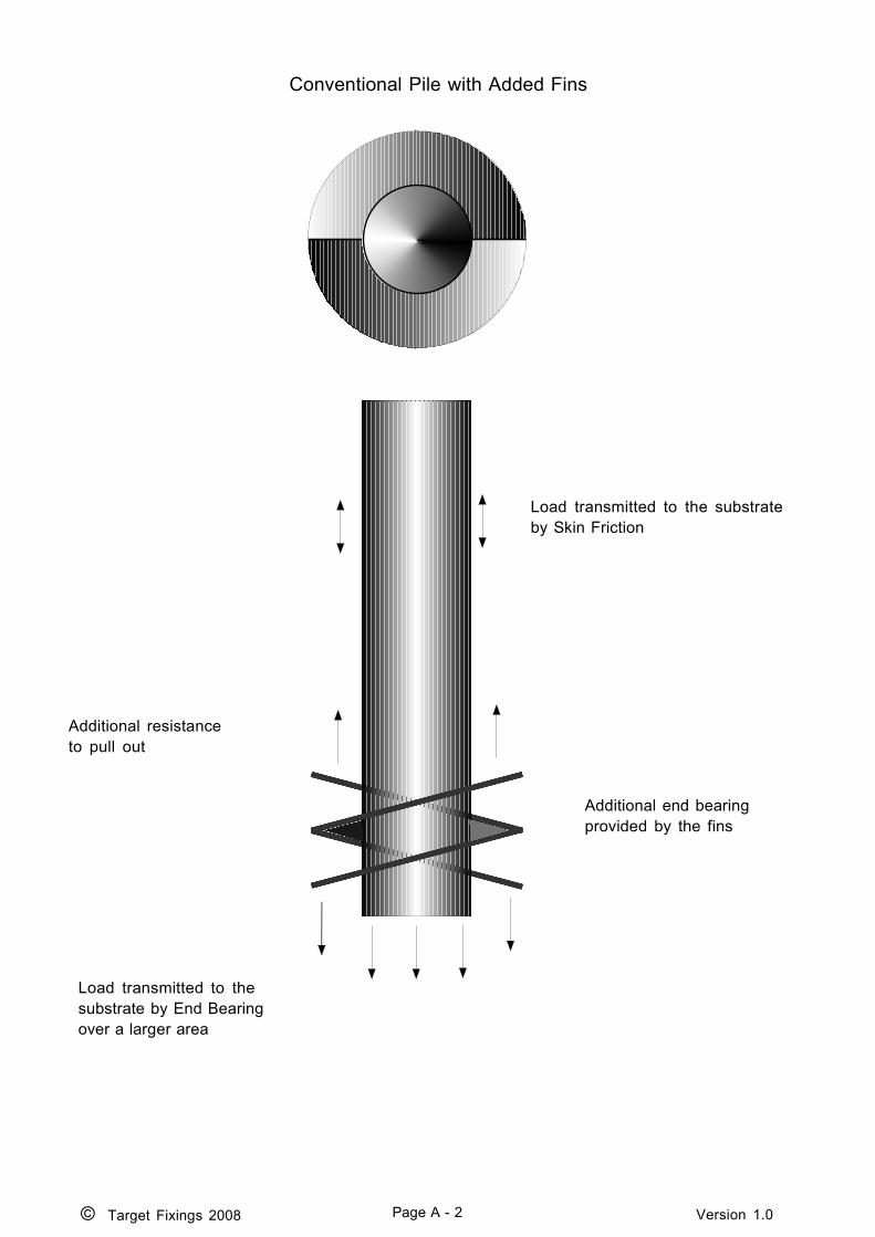
Conventional Pile with Added Fins
© Target Fixings 2008 Page A - 2 Version 1.0
Additional resistanceto pull out
Additional end bearingprovided by the fins
Load transmitted to thesubstrate by End Bearingover a larger area
Load transmitted to the substrateby Skin Friction

Target Fixings Heli Pile
© Target Fixings 2008 Page A - 3 Version 1.0
Mechanical Fix of pileinto substrate
Load transmitted to the substrateby End Bearing over a much largereffective area
Load transmitted to thesubstrate by an increasedSkin Friction
Load transmitted to the substrate byreactions perpendicular to the wedgeshaped fins.
Note.This method of transfer of the load has anumber of enhancing effects :
a. It tends to compress the surroundingmaterials. This increases the forces at thesurface of the pile normal to the frictionalforces. This leads to an increase in theavailable frictional resistance of the pile.
b. It greatly increases the cone ofinfluence of the pile and gives a largervolume within which the effect of the pilecan be applied. This gives a much largereffective end bearing area, in effectgiving the end bearing performance of amuch larger diameter pile.
Pile works in both directionsproviding very good resistance toupward as well as downward loading

© Target Fixings 2008 Page B - 1 Version 1.0
ANNEX B
DATA SHEET - LM25 (AL-Si7Mg0.5) Aluminium Casting Alloy
(This alloy conforms to BS 1490 : 1998 LM25)
CHEMICAL COMPOSITION
Copper 0 .10 %Magnesium 0.2 - 0.6 %Silicone 6.5 - 7.5 %Iron 0 .5 %Manganese 0 .3 %Nickel 0 .1 %Zinc 0 .1 %Lead 0 . 1 %Tin 0 .1 %Titanium* 0 .2 %Others (each) 0.05 max %Others (total) 0.15 max %Aluminium Remainder %
* If Titanium alone is used for grain refining, the amount present shall be not less than 0.05%
MECHANICAL PROPERTIES (LM25-M Chill Cast)
0.2% Proof Stress 9 0 N/mm2Tensile Strength 1 8 0 N/mm2Elongation 5 %Brinell Hardness 6 0Fatigue Strength (5 x 10⁸ cycles) 55 - 95 N/mm2Modulus of Elasticity (x 103) 7 1 N/mm2
PHYSICAL PROPERTIES
Coefficient of Thermal Expansion 0 .000022 per °C at 20 to 100°CThermal Conductivity 38 .4 % IACS at 25 °CElectrical Conductivity 3 9 % IACS at 20 °CDensity 2 .68 g/cm2Melting Range (approx) 550 - 615 °C
MACHINABILITY
A moderately high rate of tool wear may be expected. Liberal cutting lubricant should beemployed.
CORROSION RESISTANCE
Resistance to corrosive attack by sea water and marine atmospheres is high.

© Target Fixings 2008 Page B - 2 Version 1.0
CASTING CHARACTERISTICS
FLUIDITY - Good, suitable for fairly thin castings.PRESSURE TIGHTNESS - Excellent, suitable for castings required to be leak tight.HOT - TEARING - Excellent, problems due to hot tearing are rarely seenTYPICAL POURING TEMP - 710 °C. Practical pouring temperatures will depend on
the mould configuration. Care must be taken not tooverheat the melt or Magnesium may be lost, resultingin poor properties. Care with chlorination must also betaken to avoid removing Magnesium.
PATTERN MAKERS SHRINKAGE - 1.3% or 1/75
APPLICATIONS
LM25 alloy is mainly used where good mechanical properties are required in castings of a shapeor dimension requiring an alloy of excellent castability in order to achieve the desired standard ofsoundness. The alloy is also used where resistance to corrosion is an important considerationparticularly where high strength is also required. It has good weldability.
Consequently LM25 finds applications in the food, chemical, marine, electrical, construction andmany other industries, and, above all, road transport vehicles where it is used for wheels,cylinder blocks and heads, and other engine and body castings. It is, in practice, the generalpurpose high strength casting alloy. It is also used in the nuclear energy installations and foraircraft parts.

Materials Technology
Corrosion properties of aluminium castings forautomotive and marine applications
Astrid Bjørgum and Anne Lise DonsSINTEF Materials Technology
IntroductionDue to high material thickness corrosion is not considered as a big problem for aluminium castings. Usually, corrosionresulting in small pits and discolouring in the outer surface can be accepted as long as the mechanical properties are notaffected. Additionally, nice surface appearance is not questioned. Corrosion properties of aluminium castings are thereforenot investigated to the same extent as wrought aluminium alloys, and few systematic investigations are available.Due to global warming and other environmental problems, weight reduction of vehicles has become a demand. Weightreduction is achieved by introduction of light metal components resulting in an increased use of aluminium in the automotiveindustry. In future vehicles further weight loss reduction can be achieved by reducing the material thickness. Thus, corrosionproperties will be of vital importance for the properties and life time of such components.In the NorLight project Shape Castings of Light Metal corrosion properties of aluminium casting alloys of interest for theautomotive industry are investigated. The effect of alloy composition, variation in microstructure and surface properties arefocused.
Alloy Foundry alloys Laboratory cast alloysDC castalloys
Net shapecastings
Unmodifiedvariants
P(Cu) -modified
Srmodified
Mgcontent
AlSiAlSi7AlSi11
AlSi7AlSi11
AlSi5AlSi7AlSi11AlSi14AlSi25
AlSi7AlSi11AlSi14AlSi25
AlSi70,20,01 - 0.50,20,20,2
Alloy DC castalloys
Net shapecastings
Laboratoryvariants
Sicontent
Mncontent
AlMg(Si) AA6063AA5082
AlMg3 AlMg2.5AlMg4.5
0.1 - 0.80.2 - 1.2
0.2 - 1.00.3 - 1.3
Test materials
Corrosion testingCorrosion testing is carried out by immersion in natural sea water and in an acetic acid acidified synthetic sea water solution (ASTM G85). Corrosion susceptibility is evaluated by weight loss measurements and pitting corrosion studies.
AlSi7 AlSi7Mg0.5
Microstructure of AlSi7 withand without 0.5% Mg
Effect of Si and Mn on corrosion ofAlMg(Si) in natural sea water
0
2
4
6
8
10
Al-4.5%
Mg
Al-4.5%
Mg+1%
Si
Al-4.5%
Mg+1%
Mn
Al-4.5%
Mg+1%
Mn+1%
Si
Al-2.5%
Mg
Al-2.5%
Mg+0.5
%Si
Al-2.5%
Mg+1%
Mn
Al-2.5%
Mg+1%
Mn+0.5
%Si
Alloy
Ave
rage
cor
rosi
on ra
te [µ
m/y
r] 4,5% Mg 2,5% Mg
1,2%
Si
0,7%
Si
1% M
n +
0,8%
Si
1,3%
Mn
+ 1,
2% S
i
1% M
n
0,9%
Mn
0,3%
Mn
+ 0,
2% S
i
0,2%
Mn
+ 0,
2% S
i
Effect of Mg and modification on corrosionof AlSi7 in natural sea water
0
20
40
60
80
100
Al-7%Si
Al-7%Si+S
r
Al-7%Si+P
+Cu
Al-7%Si+0
.2%Mg
Al-7%Si+0
.2%Mg+
Sr
Al-7%Si+0
.2%Mg+
P+Cu
Al-7%Si+0
.2%Mg+
P+Cu
Al-7%Si+0
.5%Mg
Al-7%Si+0
.5%Mg+
Sr
Al-7%Si+0
.5%Mg+
P+Cu
Alloy
Ave
rage
cor
rosi
on ra
te [µ
m/y
r]
No Mg 0.2% Mg 0.5% Mg
: Unmodified : Sr : P + Cu
As expected, AlMg(Si) alloys had low corrosion ratesin natural sea water. The corrosion rate of AlSicastings were higher. The effect of Si on corrosionsusceptibility of AlSi was not clear.
Addition of Mn and Si had a minor effect oncorrosion susceptibility of AlMg(Si) although adistinct difference in microstructure was observed.
The effect of increased Mg content (0 - 0.5%) onAlSi alloys was negligible. Modification of AlSi had aminor effect on the corrosion susceptibility. Anapparently increase in corrosion rate for P(Cu)modified alloys is probably resulted by the increasein Cu content.
Effect on environmental conditions on corrosionof AlMg and AlSi net shape castingsDifferences in surface morphology had a negligibleeffect on corrosion susceptibility of AlSi in naturalsea water. A more porous microstructure wasprobably the main reason for higher corrosion rate ofnet shape AlMg castings compared to machinedAlMg castings.Exposure in the acidified SWAAT solution resulted inincreased corrosion rates, particularly for the AlMgcastings. The protective Mg containing oxideresulting in high corrosion resistance for such alloysin natural sea water, is not stable in acidicenvironments.
Corrosion of net shape castingsin SWAAT solution
0,0
0,2
0,4
0,6
0,8
1,0
1,2
1,4
1,6
1,8
2,0
AlMg3-P AlMg3-Sek AlSi7 AlSi11 A-356 A-356-VB F-356
Alloy
Ave
rage
cor
rosi
on ra
te [m
m/y
r]
AlMg3AlSi
Corrosion of net shape castingsin natural sea water
0
20
40
60
80
100
AlMg3-P AlMg3-S AlSi7 AlSi11 A-356 A-356-VB F-356
Alloy
Ave
rage
cor
rosi
on ra
te [µ
m/y
r]
AlSi
AlMg3
Microstructure of AlMg4.5
200 µm 200 µm
0.2% Si+0.3% Mn1% Si+1% Mn
ResultsCorrosion of AlSi and AlMg in natural sea water
0
20
40
60
80
100
AlSi7 (In
d)A35
6
AlSi7Mg0
,3 (In
d)
AlSi11Mg0
,2 (In
d)
AlSi11Mg0
,5 (In
d)
AlSi7 (La
b)
AlSi7Mg0
,2 (La
b)
AlSi7Mg0
,5 (La
b)
AlSi11Mg0
,2 (La
b)
AlSi14Mg0
,2 (La
b)
AlSi25Mg0
,2 (La
b)
AlMg3
Si0,3 (La
b)
AlMg2
,5 (La
b)
AlMg4
,5 (La
b)
AlMg4
,7 - 5
182 (
Ind)
AlMg0
,5Si0.
5 - 60
63 (In
d)
Alloy
Ave
rage
cor
rosi
on ra
te [µ
m/y
r] Ind AlSiLab AlSi Ind 5082
Ind 6063
Lab AlMg
© Target Fixings 2008 Page C - 1 Version 1.0
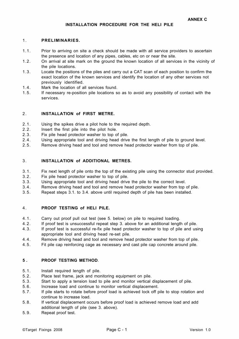
ANNEX CINSTALLATION PROCEDURE FOR THE HELI PILE
1 . PRELIMINARIES.
1.1. Prior to arriving on site a check should be made with all service providers to ascertainthe presence and location of any pipes, cables, etc on or near the site.
1.2. On arrival at site mark on the ground the known location of all services in the vicinity ofthe pile locations.
1.3. Locate the positions of the piles and carry out a CAT scan of each position to confirm theexact location of the known services and identify the location of any other services notpreviously identified.
1.4. Mark the location of all services found.1.5. If necessary re-position pile locations so as to avoid any possibility of contact with the
services.
2 . INSTALLATION of FIRST METRE.
2.1. Using the spikes drive a pilot hole to the required depth.2.2. Insert the first pile into the pilot hole.2.3. Fix pile head protector washer to top of pile.2.4. Using appropriate tool and driving head drive the first length of pile to ground level.2.5. Remove driving head and tool and remove head protector washer from top of pile.
3 . INSTALLATION of ADDITIONAL METRES.
3.1. Fix next length of pile onto the top of the existing pile using the connector stud provided.3.2. Fix pile head protector washer to top of pile.3.3. Using appropriate tool and driving head drive the pile to the correct level.3.4. Remove driving head and tool and remove head protector washer from top of pile.3.5. Repeat steps 3.1. to 3.4. above until required depth of pile has been installed.
4 . PROOF TESTING of HELI PILE.
4.1. Carry out proof pull out test (see 5. below) on pile to required loading.4.2. If proof test is unsuccessful repeat step 3. above for an additional length of pile.4.3. If proof test is successful re-fix pile head protector washer to top of pile and using
appropriate tool and driving head re-set pile.4.4. Remove driving head and tool and remove head protector washer from top of pile.4.5. Fit pile cap reinforcing cage as necessary and cast pile cap concrete around pile.
5 . PROOF TESTING METHOD.
5.1. Install required length of pile.5.2. Place test frame, jack and monitoring equipment on pile.5.3. Start to apply a tension load to pile and monitor vertical displacement of pile.5.6. Increase load and continue to monitor vertical displacement.5.7. If pile starts to rotate before proof load is achieved lock off pile to stop rotation and
continue to increase load.5.8. If vertical displacement occurs before proof load is achieved remove load and add
additional length of pile (see 3. above).5.9. Repeat proof test.

© Target Fixings 2008 Page C - 2 Version 1.0
INSTALLATION PROCEDURE FOR THE HELI PILE WITH STEEL FRAMES
6 . PRELIMINARIES.
6.1. Prior to arriving on site a check should be made with all service providers to ascertainthe presence and location of any pipes, cables, etc on or near the site.
6.2. On arrival at site mark on the ground the known location of all services in the vicinity ofthe pile locations.
6.3. Mark location of frame on site and locate the positions of the piles and carry out a CATscan of each position to confirm the exact location of the known services and identify thelocation of any other services not previously identified.
6.4. Mark the location of all services found.6.5. If necessary re-position the frame and pile locations so as to avoid any possibility of
contact with the services.
7 . INSTALLATION of FIRST METRE.
7.1. Mark position of frame on site and excavate soil to allow frame to sit below ground level.7.2. Assemble frame in position and locate position of piles using the frame as a template.7.3. Using the frame as a template use a spike to drive a pilot hole to the required depth.7.4. Insert the first length of pile through the frame and into the pilot hole.7.5. Fix pile head protector washer to top of pile.7.6. Using appropriate tool and driving head drive the first length of pile to frame level.7.7. Remove driving head and tool and remove head protector washer from top of pile.
8 . INSTALLATION of ADDITIONAL METRES.
8.1. Fix next length of pile onto the top of the existing pile using the connector stud provided.8.2. Fix pile head protector washer to top of pile.8.3. Using appropriate tool and driving head drive the pile to frame level.8.4. Remove driving head and tool and remove head protector washer from top of pile.8.5. Repeat steps 8.1. to 8.4. above until required depth of pile has been installed.
9 . PROOF TESTING of HELI PILE.
9.1. Carry out proof pull out test (see 5 above) on pile to required proof loading.9.2. If proof test is unsuccessful repeat steps 8 above with an additional length of pile.9.3. If proof test is successful re-fix pile head protector washer to top of pile and using
appropriate tool and driving head re-set pile and drive to required depth (If top of pile isrequired to terminate below the top of the pile fixing tube on the frame use a short lengthof pile as an temporary extension piece to drive the pile into the tube).
9.4. Remove driving head and tool and remove head protector washer from top of pile.9.5. Repeat above for all remaining piles.9.6. Check level and position of frame.9.7. Secure piles to frame using method appropriate to type of frame being used.9.8. Back fill around frame using material previously excavated.

© Target Fixings 2008 Page D - 1 Version 1.0
ANNEX D
HELI PILE STANDARD DETAILS
Number Description
HP-01 Repairing brick retaining walls - Slip plane
HP-02 Repairing brick retaining walls - Homogeneous unit
HP-03 Supporting concrete strip footings (Twin Piles)
HP-04 Supporting concrete strip footings (Single pile)
HP-05 Helical Pile capping details
HP-06 Supporting solid walls (Twin Piles with wall as part of cap)
HP-07 Supporting cavity walls (Twin Piles with wall as part of cap)
HP-08 Supporting solid walls (Twin Piles with new cast cap)
HP-09 Supporting cavity walls (Twin Piles with new cast cap)
HP-10 Supporting stepped footings (Twin Piles with cast caps)
HP-1 1 Supporting concrete strip footings (Twin Piles with cast caps)
HP-12 Supporting solid walls (Single pile with underpinned cast cap)
HP-13 Supporting cavity walls (Single Pile with cast cap - 3 Bars)
HP-15/1 Heli Pile - Heave Situations - Intermediate tests above andbelow desiccation level.
HP-15/2 Heli Pile - Heave Situations - Spike and test below desiccationlevel.
HP15/3 Heli Pile - Heave Situations - Spike and sleeve top of pile.

© 2007 : Target Fixings Ltdv3.2
Target Fixings LtdTel: 01635 58 00 88Email: [email protected]: www.targetfixings.com
HP - 01
Repair Brick Retaining WallsHeli Pile with Bar Flex

© 2007 : Target Fixings Ltdv3.2
Target Fixings LtdTel: 01635 58 00 88Email: [email protected]: www.targetfixings.com
HP - 02
Repair Brick Retaining WallsHomogeneous Unit - Heli Pile with Bar Flex

© 2007 : Target Fixings Ltdv3.2
Target Fixings LtdTel: 01635 58 00 88Email: [email protected]: www.targetfixings.com
HP - 03
Support Concrete Strip Footings

© 2007 : Target Fixings Ltdv3.2
Target Fixings LtdTel: 01635 58 00 88Email: [email protected]: www.targetfixings.com
HP - 04
Support Concrete Strip FootingsSingle Heli Pile
© 2007 : Target Fixings Ltdv3.2
Target Fixings LtdTel: 01635 58 00 88Email: [email protected]: www.targetfixings.com
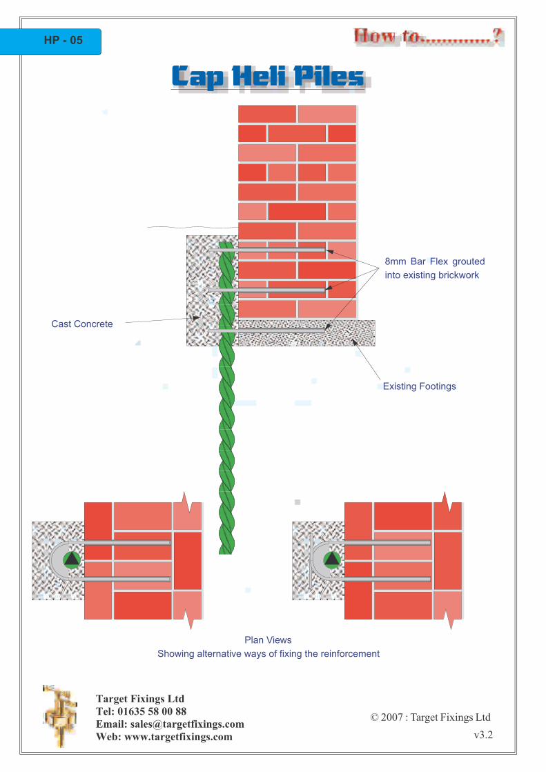
HP - 05
Cast Concrete
8mm Bar Flex groutedinto existing brickwork
Existing Footings
Plan ViewsShowing alternative ways of fixing the reinforcement
Cap Heli Piles

© 2007 : Target Fixings Ltdv3.2
Target Fixings LtdTel: 01635 58 00 88Email: [email protected]: www.targetfixings.com
HP - 06
Cast Concrete
8 mm Bar Flex groutedinto existing brickworkand then cast intoconcrete
Plan ViewShowing way of fixing the reinforcement
Cap Heli PilesUsing Existing Wall as Part of Pile Cap

© 2007 : Target Fixings Ltdv3.2
Target Fixings LtdTel: 01635 58 00 88Email: [email protected]: www.targetfixings.com
HP - 07
Cavity filled to within150mm of D.P.C.
Existing Footing
D.P.C.
Cast Concrete
8mm Bar Flex groutedinto existing brickworkand then cast intoconcrete
Plan ViewShowing way of fixing the reinforcement
Cap Heli PilesUsing Existing Wall as Part of Pile Cap

© 2007 : Target Fixings Ltdv3.2
Target Fixings LtdTel: 01635 58 00 88Email: [email protected]: www.targetfixings.com
HP - 08
Cast Concrete
8mm Bar Flex usedas reinforcement
Plan ViewShowing way of fixing the reinforcement
Casting New Concrete Pile Cap Through/Under Solid Wall
Cap Heli Piles
© 2007 : Target Fixings Ltdv3.2
Target Fixings LtdTel: 01635 58 00 88Email: [email protected]: www.targetfixings.com
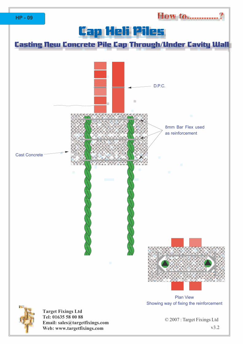
HP - 09
D.P.C.
Plan ViewShowing way of fixing the reinforcement
Cast Concrete
8mm Bar Flex usedas reinforcement
Casting New Concrete Pile Cap Through/Under Cavity Wall
Cap Heli Piles

© 2007 : Target Fixings Ltdv3.2
Target Fixings LtdTel: 01635 58 00 88Email: [email protected]: www.targetfixings.com
HP - 10
Existing footings core drilledto allow pile to be driventhrough. Pile is thengrouted into brickwork.
Cast Concrete
8mm Bar Flex groutedinto existing brickworkand then cast intoconcrete
Plan ViewShowing way of fixing the
reinforcement
Solid Wall on Stepped Footings with Cast Concrete Cap
Cap Heli Piles

© 2007 : Target Fixings Ltdv3.2
Target Fixings LtdTel: 01635 58 00 88Email: [email protected]: www.targetfixings.com
Existing Footings
Existing footings core drilledto allow pile to be driventhrough. Pile is thengrouted into concrete.
Cast Concrete
Plan ViewShowing way of fixing the
reinforcement
8 mm Bar Flex groutedinto existing brickworkand then cast intoconcrete
HP - 11
Concrete Strip Footings With Cast Concrete Cap
Cap Heli Piles

© 2007 : Target Fixings Ltdv3.2
Target Fixings LtdTel: 01635 58 00 88Email: [email protected]: www.targetfixings.com
Cast Concrete
Plan ViewShowing way of fixing the reinforcement
8mm Bar Flex grouted intoexisting brickwork andthen cast into concrete
8mm Bar Flex driven intoside of excavation andthen cast into concrete
HP - 12
Solid Wall With Underpinned Cast Concrete Cap
Cap Heli Piles

© 2007 : Target Fixings Ltdv3.2
Target Fixings LtdTel: 01635 58 00 88Email: [email protected]: www.targetfixings.com
Cast Concrete Cap
Plan ViewShowing way of fixing the reinforcement
8mm Bar Flex groutedinto existing concretefootings and then castinto concrete cap
Existing Concrete footings
HP-13
Cavity Wall with Cast Concrete Cap onto Footings
Cap Heli Piles

Heli Pile - Heave Situations
Intermediate tests above and below desiccation level
© 2004 : Target Fixings v 1.0
1. Spike as normal (A).
2. Drive pile to depth of desiccation/zone of
influence and perform tension test (B).
3. Drive pile to required depth and performsecond tension test (C).
4. Difference between B and C is resistance to heave for the pile.
5. Connect pile back to existing structure (D).
6. Cast concrete cap and make good (E).
A
B
C D E
HP-15/1

Heli Pile - Heave Situations
Spike and test below desiccation level
© 2004 : Target Fixings v 1.0
1. Spike as normal to requireddepth and then over spike(60/100 mm) to depth ofdesiccation (A).
2. Drive pile to required depth (B).
3. Perform tension test (C). This loading is the resistance to heave of the pile.
4. Connect pile back to existing structure and fill space around pile with sharp sand (D).
5. Cast concrete cap and make good (E).
A B C D E
HP-15/2

Heli Pile - Heave Situations
Spike and sleeve top of pile
© 2004 : Target Fixings v 1.0
1. Spike as normal to required depth and then overspike (70/110 mm) to depth of desiccation (A).
2. Insert plastic sleeve into over spiked hole(B).
3. Drive pile to required depth and performtension test (C). This loading is the resistanceto heave of the pile.
4. Connect pile back to existing structure and fill space around pile with sharp sand (D).
5. Cast concrete cap and make good (E).
A B C D E
HP-15/3

TYPICAL USES OF THE HELI PILEANNEX E
Fabricated basesfor
Piled concrete strip foundations
Steel or timber fabricatedfoundation system
Piled concrete slab or raft
© Target Fixings 2008 Page E - 1 Version 1.0

Various Designs of Fabricated Heli Pile Caps
Caps to fit wooden posts tothe top of the Heli Piles
Caps to fit fabricated structures tothe top of the Heli Piles
© Target Fixings 2008 Page E - 2 Version 1.0

©Target Fixings 2008 Page F - 1 Version 1.0
ANNEX FHELI PILE PERFORMANCE GUIDE
The table below shows typical/average loads for the Heli Pile when installed in a metre of agiven soil.Example: A 60mm Heli Pile installed through 2m of Top Soil/Loose Fill and then into 1m ofMedium Clay should achieve a tensile proof test load of around 20kN to 25kN.If Heli Piles are to be installed in very dense materials, such as mud stone, a pilot hole mayneed to be cored so as the Heli Pile can be driven home to provide a mechanical fix or grouted.
SPT 60mm Heli Pile 100mm Heli PileSoil Type N Loads are per 1 Loads are per 1
Value metre embedment metre embedment
Compression Tension Compression Tension( k N ) ( k N ) ( k N ) ( k N )
Top soil/Loose fill 0 - 5 8 5 1 0 7
Soft Clay 1 - 4 1 0 7 15 - 20 10 - 20
Firm Clay 4 - 8 15 - 20 10 - 15 30 - 40 25 - 35
Stiff Clay 8 - 20 30 - 40 25 - 30 70 - 90 40 - 60
Soft Sandy Clay 1 - 4 15 - 20 7 15 - 20 12 - 15
Firm Sandy Clay 4 - 8 25 - 30 15 - 20 40 - 50 30 - 35
Stiff Sandy Clay 8 - 20 40 - 50 25 - 30 70 - 90 40 - 50
Boulder Clay 4 - 15 25 - 30 18 - 25 25 - 30 20 - 25
Clay Stone 20+ 5 0 5 0 150 150
Mud Stone 50+ 5 0 5 0 150 150
Rock 50+ 5 0 5 0 150 150
Putty Chalk 0 - 5 9 5 1 2 8
Soft Chalk 5 - 10 1 8 1 2 2 5 19x
Dense Chalk 10 - 40 5 0 5 0 150 135
Chalk Rock 40+ 5 0 5 0 150 150
Sandy Gravels 20 - 40 30 - 40 10 - 20 40 - 60 15 - 30
Gravel Beds 30 - 50 5 0 30 - 40 150 20 - 60
The above information is given as a guide only.There is NO substitute for in situ testing of the Heli Pile and all Heli Piles must be proof testedin situ on site. The SPT N Values are given as a guide only. These should be taken in situ on siteand quantified by a mean amount.Soils vary infinitely and the above are taken as their average condition from the data availableto provide this guide.