Embed Size (px)
DESCRIPTION
Parabolic concentration mirrors, and generation of Electricity through solar Power.This study was done as a project of final education at the lebanese univeristy of Engineering
Citation preview

Lebanese UniversityFaculty of Engineering II
Final year project
submitted in fulfillment of the requirements for the
Diploma of Mechanical Engineering
by
Alain KARAMAbdo CHAMIEHAlain FAKHRY
Solar Thermal Power Plant
Parabolic Trough Technology
Project supervisor : Dr. Francois KHOURY
2011


Acknowledgements
Apart from our efforts, the success of any project depends largely on the encouragement and guidelines of many others.
We would like to thank Phoenix Member of Indevco group for proposing this challenging project and offering their help even if we didn’t manage to continue working with them.
We wish to thank the Lebanese University – Faculty of Engineering – Branch II, and we would like to offer our sincerest gratitude to our supervisor, Dr. Francois Khoury, who has supported us throughout our thesis with his patience and knowledge.
Needless to mention Dr.Khalil Khoury for his able guidance and useful suggestions which helped us in starting our project.
Many thanks go to Mr. Bernard Ammoun for offering his help and advice concerning markets in and outside Lebanon that sells solar technology parts required for the project, and taking care of transporting the steam engine from the United States of America.
Special thanks for Engineer Souad Chamieh for sharing her experience in programming and spending many hours working on the software with us.
We would like to express our heartfelt thanks to our beloved parents for their blessing, help, and wishes for the successful completion of this project.
The biggest thanks go to God who made all things possible.
1

Abstract:
Solar Thermal Power Plant:
Solar thermal power is a relatively new technology which has already shown enormous promise. Solar thermal power uses direct sunlight, so it must be sited in regions with high direct solar radiation.
The purpose of our project (CSP) is producing electricity without the use of fossil fuel and only using the sun’ s power
The first step of the project is to prove that Lebanon is suitable for solar applications.
The second step is generally focusing on several technologies used for producing electricity and showing the advantages and disadvantages of each one including the differences between them.
The third step is to study the parabolic trough technology including the solar field, the usual thermodynamic rankine cycle, and all the formulas needed to complete the calculation. Briefly, how much solar power needed to produce a certain amount of electricity?
The fourth step is to make a software in which the user enters some needed parameters, for example the electrical power and gives how many collectors is needed in the solar field as an output...
The final step is to make a prototype showing the conversion of sun’s heat to electrical power.
2

Central Solaire:
L'énergie solaire thermique est une technologie relativement nouvelle qui a déjà montré une énorme puissance de promise. L'énergie solaire thermique utilise la lumière solaire directe, donc il doit être situé dans les régions à forte radiation solaire directe. Le but de notre projet (CSP) est la production d'électricité sans l'utilisation de combustibles fossiles et en utilisant uniquement la puissance du soleil.
La première étape du projet est de prouver que le Liban est adapté pour les applications solaires.
La deuxième étape est généralement axé sur plusieurs technologies utilisées pour la production d'électricité et de montrer les avantages et les inconvénients de chacun, y compris les différences entre eux.
La troisième étape consiste à étudier la technologie cylindro-paraboliques dont le domaine solaire, le cycle thermodynamique d'habitude Rankine, et toutes les formules nécessaires pour terminer le calcul. En bref, combien d'énergie solaire nécessaire pour produire une certaine quantité d'électricité?
La quatrième étape est de faire un logiciel dans lequel l'utilisateur saisit quelques paramètres nécessaires, par exemple l'énergie électrique et donne le nombre de collectionneurs qui est nécessaire dans le domaine solaire comme une sortie ...
La dernière étape consiste à réaliser un prototype montrant la conversion de la chaleur du soleil en énergie électrique.
3

Table of contents
Acknowledgements..............................................................................................................................2
Abstract:..............................................................................................................................................3
1 Introduction.................................................................................................................................7
2 Concentration Solar Power Technology overview: (CSP)...............................................................10
2.1 Parabolic Trough:......................................................................................................................10
2.2 Parabolic dish concentrators (Dish Stirling):............................................................................11
2.3 Central Receiver or Power Tower:............................................................................................12
2.4 Fresnel solar power system:.....................................................................................................13
3 Parabolic trough.........................................................................................................................15
3.1 Solar field:.................................................................................................................................15
3.2 Collector:...................................................................................................................................16
3.3 Receiver.....................................................................................................................................17
3.4 Heat Transfer Fluid: (HTF).........................................................................................................18
3.4.1 Impact of salt HTF on the power plant performance.......................................................20
3.4.2 Advantages and disadvantages of using molten salt as a HTF:........................................21
3.4.3 Molten salt system Issues:................................................................................................21
3.4.4 Routine freeze protection operation:...............................................................................21
3.4.5 Solar Field Preheat Methods:............................................................................................22
3.4.6 Collector Loop Maintenance with an Impedance Heating System:.................................23
3.4.7 Materials consideration:...................................................................................................24
3.5 losses and efficiencies...............................................................................................................26
3.5.1 Optical losses:....................................................................................................................26
3.5.2 Thermal losses:..................................................................................................................28
3.5.3 Geometrical losses:...........................................................................................................29
3.6 SOLAR ANGLES:.........................................................................................................................29
3.8 Fluid pump:...............................................................................................................................32
3.8.1 Materials and Temperatures:...........................................................................................33
3.8.2 Standard High Temperature Pump Designs:.....................................................................34
3.8.3 Mounting and Sealing Molten Salt Pumps:......................................................................35
3.9 Tracking system:........................................................................................................................35
3.10 Thermal Storage Systems for Concentrating Solar Power........................................................36
3.10.1 Two-Tank Direct System....................................................................................................37
4

3.10.2 Two-Tank Indirect System.................................................................................................37
3.10.3 Single-Tank Thermocline System......................................................................................38
4 Industrial Process..........................................................................................................................39
4.1 Basic Process and Components:...............................................................................................39
4.2 Steam Turbine:..........................................................................................................................41
4.2.1 Types of Steam Turbines:..................................................................................................42
Non-Condensing (Back-pressure) Turbine:...................................................................................43
Extraction Turbine:........................................................................................................................44
4.3 Heat Exchangers:.......................................................................................................................45
4.3.1 Exchanger Equation:..........................................................................................................47
4.3.2 Types of Exchangers:.........................................................................................................47
5 Designing an 8.5 Mwe solar thermal power plant..........................................................................51
6 Practical study................................................................................................................................54
Appendix VB Programming...............................................................................................................61
References:........................................................................................................................................68
5

1 Introduction
Solar energy as a power from the sun is a vast and inexhaustible resource. Once a system is in place to convert it into useful energy, the fuel is free and will never be subject to the ups and downs of energy markets. Furthermore, it represents a clean alternative to the fossil fuels that currently pollute our air and water, threaten our public health, and contribute to global warming. Given the abundance and the appeal of solar energy, this resource is poised to play a prominent role in our energy future.
So the advantages of using solar energy are:
Unlimited alternative fuel Free alternative fuel Clean alternative fuel that means no pollution and health threat Fighting the global warming
Solar energy supports all life on Earth and is the basis for almost every form of energy we use. The sun makes plants grow, which can be burned as biomass fuel or, if left to rot in swamps and compressed underground for millions of years, in the form of coal and oil. Heat from the sun causes temperature differences between areas, producing wind that can power turbines. Water evaporates because of the sun, falls on high elevations, and rushes down to the sea, spinning hydroelectric turbines as it passes. But solar energy usually refers to ways the sun's energy can be used to directly generate heat, lighting, and electricity.
In our project, we are going to study how solar energy can be used to generate heat, and how this heat is converted to electricity. By using mirrors and lenses to concentrate the rays of the sun, solar thermal systems can produce very high temperatures, generating steam to produce electricity using steam turbines. One of the greatest benefits of large scale solar thermal systems is the possibility of storing the sun’s heat energy for later use, which allows the production of electricity even when the sun is no longer shining. Properly sized storage systems, commonly consisting of molten salts, can transform a solar plant into a supplier of continuous base load electricity. Solar thermal systems now in development will be able to compete in output and reliability with large coal and nuclear plants.
To decide what if a country is suitable to a solar application, we should define the solar radiation and its value in this country. So Insolation is a measure of solar radiation energy received on a given surface area in a given time. It is commonly expressed as average irradiance in watts per square meter (W/m2) or kilowatt-hours per square meter per day (kWh/(m2·day))
6

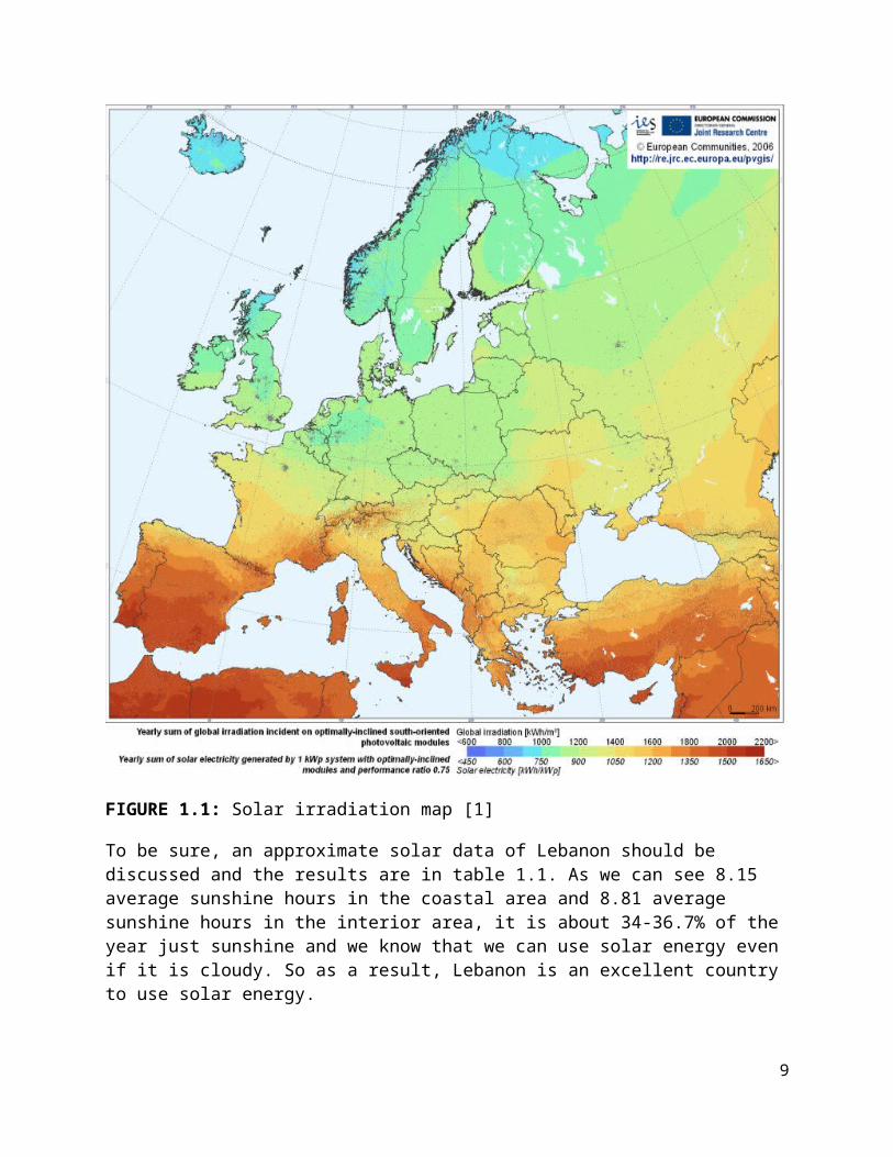
(or hours/day). Figure 1.1 shows that Lebanon is one of the best countries in solar radiation in this region which means that is a suitable country for solar applications.
FIGURE 1.1: Solar irradiation map [1]
To be sure, an approximate solar data of Lebanon should be discussed and the results are in table 1.1. As we can see 8.15 average sunshine hours in the coastal area and 8.81 average sunshine hours in the interior area, it is about 34-36.7% of the year just sunshine and we know that we can use solar energy even if it is cloudy. So as a result, Lebanon is an excellent country to use solar energy.
7

Month Coastal insolation, kWh/m2/day
Interior insolation, kWh/m2/day
Coastal sunshine hours
Interior sunshine hours
Day length
January 2.4 2.4 4.6 4.5 10
February 3.2 3.4 5.6 5.5 10.8
March 4.1 4.4 6.4 6.4 11.8
April 5.5 5.9 7.7 8.5 12.9
May 6.6 7.2 10.1 10.5 13.8
June 7.3 8.5 11.5 13.1 14.2
July 7.0 8.4 11.4 13.2 14
August 6.3 7.7 10.6 12.4 13.2
September 5.3 6.5 10.4 11.2 12.1
October 4 4.7 8.1 9 11
November 2.9 3.3 6.4 6.7 10.2
December 2.3 2.4 5 4.8 9.8
Average 4.74167 5.4 8.15 8.8167 11.9833
Table 1.1: Solar data for Lebanon [2]
8

2 Concentration Solar Power Technology overview: (CSP)
CSP technologies are solar thermal plants (STP) that produce electricity in the same way as conventional power stations, except that they obtain part of their thermal energy input in a different way by using mirrors to reflect and concentrate sunlight onto receivers where a working fluid passes from low to high temperatures. The resulting heat energy is used to power a steam turbine, or alternatively to move a piston in a sterling engine. Tracking techniques are required in these systems to ensure that the maximum amount of sunlight enters the concentration system. Essentially, STP plants include four main components: the concentrator, receiver, transport-storage, and power conversion. Many different types of systems are possible using variations of the above components, combining them with other renewable and nonrenewable technologies, and in some cases, adapting them to utilize thermal storage. The four most promising solar power architectures are:
Parabolic Trough Center Receiver or Power Tower Parabolic Dish Fresnel Reflector
2.1 Parabolic Trough:
A parabolic trough system consists of many long parallel rows of curved mirrors that concentrate light onto a receiver pipe positioned along the reflector’s focal line, as shown in Figure 2.1. The troughs follow the trajectory of the sun by rotating along their axis to ensure that the maximum amount of sunlight enters the concentrating system. The concentrated solar radiation heats up a fluid circulating in the pipes, typically synthetic oil or molten salt, to temperatures of up to 750°F (approximately 400°C). The hot oil is pumped to heat exchangers to generate steam, which is used to drive a conventional steam turbine generator. A schematic diagram of a solar power plant using parabolic trough concentrators is shown in Figure 2.2.
Figure 2.1: schematic of a parabolic trough collector [3]
9
Solar power is intermittent and is not available overnight; therefore, some solar power plants are designed to operate as hybrid solar/fossil plants. As hybrids, they have the capability to generate electricity during periods of low solar radiation. The new parabolic trough plants use molten salt for the heat transfer medium, which is cheaper and safer than oil. Also, because salts are an effective storage medium, the spare solar power is used in the form of heated molten salt in storage tanks, for use during periods when solar power is not available. This makes the CSP technology truly dispatchable.
Figure 2.2: Schematic diagram of a solar power plant with parabolic trough concentrators. [3]
2.2 Parabolic dish concentrators (Dish Stirling):
A parabolic dish concentrator consists of a parabolic dish-shaped mirror that reflects solar radiation onto a receiver located at the focal point of the dish. The dish structure is designed to track the sun on two axes, allowing the capture of solar energy at its highest density. A schematic of a parabolic dish concentrator is shown in Figure 2.3.
Figure 2.3: schematic of a parabolic dish concentrator [3]
10

The solar dish concentration ratio is much higher then solar trough, typicaly over 2000, with a working fluid temperature to over 1300°F (approximately 750°C). The thermal receiver consists of a bank of tubes filled with a cooling fluid, usually hydrogen or helium, which is heat transfer medium and also the working fluid for an engine. The thermal receiver absorbs the solar energy and converts it to heat that is delivered to an electric generator to generate electricity. Similar to parabolic trough, a concentrator can be made up of multiple mirrors that approximate a parabolic dish to reflect the solar energy at a central focal point. The main advantage of the solar dish technology is that the Stirling system requires no water for heating or cooling.
2.3 Central Receiver or Power Tower:
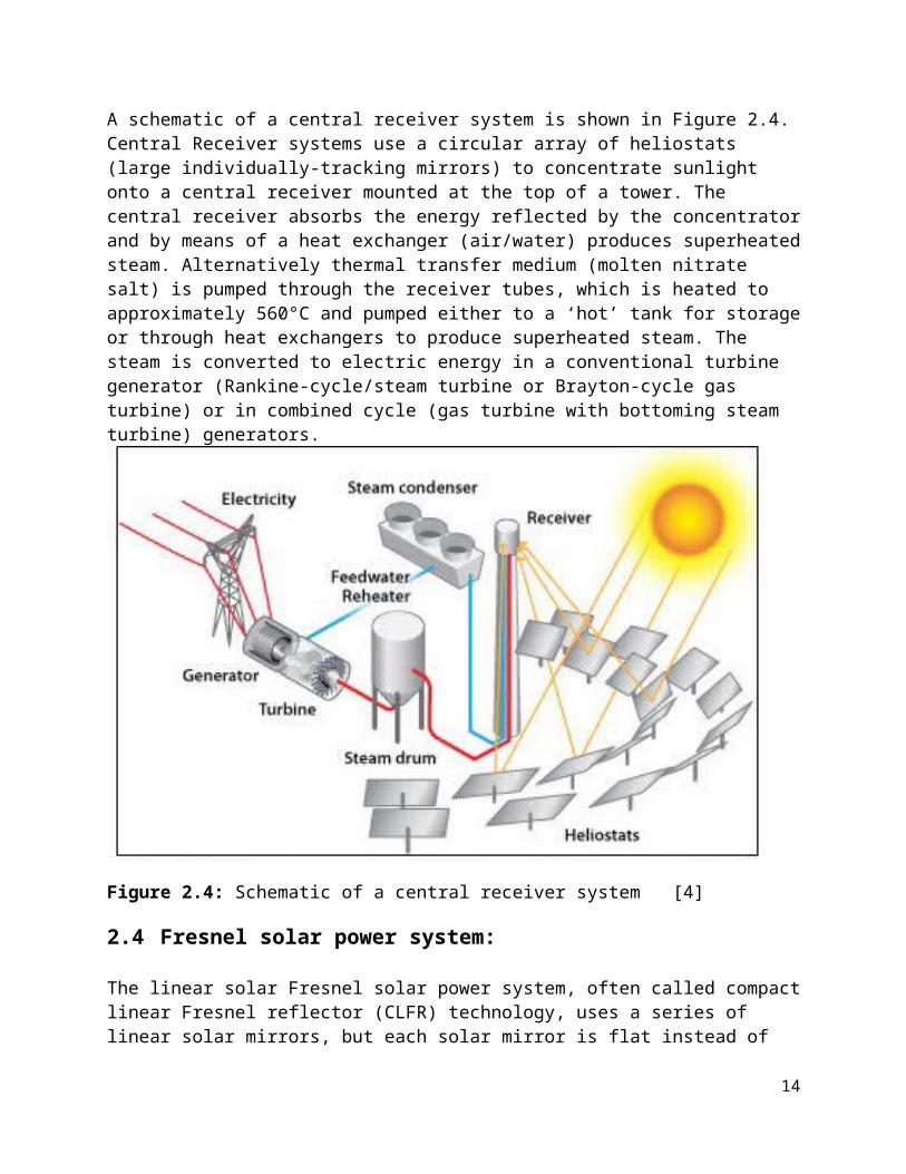
A schematic of a central receiver system is shown in Figure 2.4.Central Receiver systems use a circular array of heliostats (large individually-tracking mirrors) to concentrate sunlight onto a central receiver mounted at the top of a tower. The central receiver absorbs the energy reflected by the concentrator and by means of a heat exchanger (air/water) produces superheated steam. Alternatively thermal transfer medium (molten nitrate salt) is pumped through the receiver tubes, which is heated to approximately 560°C and pumped either to a ‘hot’ tank for storage or through heat exchangers to produce superheated steam. The steam is converted to electric energy in a conventional turbine generator (Rankine-cycle/steam turbine or Brayton-cycle gas turbine) or in combined cycle (gas turbine with bottoming steam turbine) generators.
Figure 2.4: Schematic of a central receiver system [4]
11

2.4 Fresnel solar power system:
The linear solar Fresnel solar power system, often called compact linear Fresnel reflector (CLFR) technology, uses a series of linear solar mirrors, but each solar mirror is flat instead of the more expensive parabolic shape used for a parabolic trough solar plant. Figure 2.5 shows a schematic of Fresnel system.
This is one of the solar concentrator technologies being developed to improve the efficiency for conversion of solar power to electricity. A Fresnel solar plant uses an array of single axis, linear flat mirrors to reflect sunlight onto a receiver tube. The compact linear Fresnel solar power system, however, uses a 'parabola' made up of ten flat mirrors that each rotate to follow the sun and this type of system allows the flat solar mirrors to remain near the ground, avoiding wind loads. Current designs for the linear solar Fresnel system heat water to produce steam at 545oF (approximately 285°C) in the absorber tubes. The steam is used directly to drive a turbine in a standard Rankine cycle to produce electricity, avoiding the need for a heat exchanger to produce steam from some other high temperature fluid.
Figure 2.5: schematic of a Fresnel system [5]
12

From all the following information regarding the types of concentrators used to generate electricity, a conclusion can be summarized in the table 2.1 that shows the applications, advantages, and disadvantages of the four types discussed in this chapter.
Parabolic Trough Central Receiver Parabolic Dish FresnelApplications -Grid-connected
plants;-Mid to high process heat
-Grid-connected plants;-High temperature process heat
-Stand-alone applicationsor small off-grid powersystems
-Grid connected plants, or steam generation to be used in conventional thermal power plants.
Advantages =Commercially available(over 9 billion kWh operationalexperience),-Solar collection efficiencyup to 60%, peak solar toelectrical conversion of21%;-hybrid concept proven;-storage capability
-Good mid-term perspectivefor high conversionefficiencies;-Solar collection efficiencyapprox. 46% at temps up to 565°C, peak solar to electrical conversion of 23%; -storage at high temperatures; hybrid operation possible
-Very high conversionefficiencies (peak solar toelectric conversion ofabout 30%);modularity;hybrid operation;
-flat solar mirror less expensive than parabolic mirror.-absorber tube is simpler and less expensive than that of the parabolic trough.-can be hybridized with fossil fuel backup.-structurally simpler than the parabolic trough and parabolic dish systems
Disadvantages -Lower temperatures (up to 400°C) restrict output to moderate steam qualities due to temperature limitsof oil medium.
-Capital cost projectionsnot yet proven.
-Hybrid systems have lowcombustion efficiency,and reliability yet to be proven.
-doesn't produce a fluid temperature as high as the parabolic trough or parabolic dish solar concentrators, so its thermal efficiency for conversion of solar power to electricity is lower.
13

3 Parabolic trough
Figure 3.1: Parabolic Trough [6]
3.1 Solar field:
To design a solar field, a study of the following important points is necessary:
Collector(mirror, concentrator) Receiver(Vacuum or Evacuated tube) Heat transfer fluid(HTF) losses and efficiencies Fluid pump Tracker Thermal storage systems
A simple relation between the different components of a solar field is illustrated in the following diagram:
14
3.2 Collector:
Before we start designing a collector, one should know the role of a collector (mirror, concentrator) and how it converts the sun’s thermal heat to electrical energy at the end of the process. The main idea of a collector is to transfer heat as much possible as it can to the heat transfer fluid, so in order to accomplish this, the collector should have a bigger area than the absorber tube, and the bigger the aperture area of the collector and the smaller the area of the absorber tube would lead us to a bigger concentration. So it’s clear that the geometric concentration ratio is the area of the collected sun over the area of the receiver tube. [12]
Figure 3.2: Collector and receiver shape. [7]
15

Geometric Concentrationratio= Aperture areareceiver area
(3.1)
C= AcAr
= La∗L( π∗d∗L )
= Laπ∗d
(3.2)
Where:
C : geometric concentration ratio Ac: collector aperture area Ar : receiver area La: aperture length L: mirror length d: outer diameter of the receiver pipe.
The rim angle, ф, is another parameter that should be discussed when designing a parabolic trough mirror. The rim angle as shown in figure 3.2 has usually a value between 70o and 110 o. Decreasing this value lower than 70 will lead to a smaller aperture length leading to a smaller aperture area then to a smaller concentration ratio; however, increasing the rim angle will result in increasing the reflecting surface without increasing the aperture length thus increasing the material cost without affecting the concentration ratio. The relation between the focal distance and the rim angle is: [12]
La4 f
=tanф2
(3.3)
The latest power plants uses LS-3 collector, it is the third generation collector after LS-1 and LS-2. In our project we choose to work on LS-3 collector with some changes in dimensons. After using equation 3.2 and 3.3 the characteristics of this collector are shown in Table 3.1:
Characteristic La L D C ф fValue 5.76 m 4 m 70 mm 26.2 100o 1.2083
Table 3.1: Characteristics of Power plant’s collector. [12]
3.3 Receiver
The definition of a receiver is any material that receives the heat from several sources. In a solar field, the receiver is usually a tube that receives all the heat from the concentrators. In the parabolic trough concentrator, the receiver is a vacuum tube (evacuated tube). This vacuum
16

tube is composed of an inner steel pipe surrounded by a glass tube to reduce convective heat losses from the hot steel pipe. The steel pipe has a high absorptivity (greater than 90%), and a low emissivity(less than 30% in the infrared) coating that reduces radiative thermal losses. Receiver tubes with glass vacuum tubes and antireflective coating achieve higher thermal efficiency and better annual performance, especially at higher operating temperatures. Receiver tubes with no vacuum are usually for working temperatures below 250 ˚C, because thermal losses are not so critical at these temperatures. The maximum length of a single receiver pipe is less than 6 m due to manufacturing constraints. In our case the length is 4 m. The complete receiver tube of a PTC is composed of a number of single receiver pipes welded in series up to the total length of the PTC. A typical parabolic trough concentrator vacuum receiver pipe is:
Figure 3.3 Typical receiver tube [8]
The glass-to-metal welding used to connect the glass tube and the expansion joint is a weak point in the receiver tube and has to be protected from the concentrated solar radiation to avoid high thermal and mechanical stress that could damage the welding. An aluminum shield is usually placed over the joint to protect the welds. Several chemical getters are placed in the gap between the steel receiver pipe and the glass cover to absorb gas molecules from the fluid that get through the steel pipe wall to the annulus. [12]
3.4 Heat Transfer Fluid: (HTF)
The HTF flows through the receiver, collects heat from the sun to exchange this heat with water in the steam generator to produce steam.
17

In order to choose what type of HTF we use in the power plant, a feasibility investigation of utilizing a type of HTF is a must.
The most popular heat transfer fluid used in CSP power plants are:
Therminol VP-1 (Known as solar oil) Solar salt Hitec Hitec XL ( Calcium Nitrate salt) LiNO3 mixture
As it is clear, Therminol VP-1 is the only oil, and all other HTFs are salts. Old CSP power plants use the Therminol VP-1 oil, but all the newest technologies focus on using molten salt as a HTF and we are going to know why in the following feasibility study. Table 4.2 shows the characteristics of the Nitrate salts and Therminol VP-1, a quick look at this table reveals the following results:
The freezing point is a major importance in solar thermal power plant because of the difficulties and the high cost of freeze protection system due to the need for extensive heat tracing equipment on piping and collector receiver. For this reason the conventional oil (Therminol VP-1) with 13o C freezing point is the best HTF, but between salts calcium nitrate mixture with 120o C is the most favored.
Solar salt is the most practical HTF for Tower technology applications because of his high upper operating temperature limit (600o C) which allows using the most advanced Rankine cycle turbines, but the disadvantage is its high freezing point of 220o C. Calcium nitrate salt has a good operating limit of about 500o C.
Table 3.2: Characteristics of Nitrate salts and Therminol VP-1. [9]
The High operation temperature of a molten salt is not enough to prove that is more efficient than oil, especially that a high freezing point leads to important issues that increases the capital and the O&M cost (operation and management).
18

As shown in table 3.3 the temperature rise in the solar field was varied from 100oC to 200oC. It is clear that the cost of any salt is a lot lower than oil, same as storage cost. The calcium nitrate salt is significantly less expansive in terms of energy capacity than oil at the same solar field temperature rise and over 70% lower if used at 200oC rise. What type of salt to choose? The Hitec look like is the best option because of its lower cost than the Calcium Nitrate and lower freezing point than solar salt; however, it does require an N2
cover gas in the thermal storage tanks at atmospheric pressure to prevent the Nitrite from converting to Nitrate, thus raising its freezing point. So our choice is now limited between Solar salt and Calcium Nitrate salt.
Table 3.3: Effective fluid storage cost. [10]
3.4.1 Impact of salt HTF on the power plant performance
The use of salt as HTF in the solar field has the following main effects:
Molten salt can operate at higher temperature than Therminol VP-1 used in conventional plants. Consequently, higher steam temperature can be achieved in the Rankine cycle leading to higher cycle efficiency.
Because of the higher operation temperature in solar field, higher heat losses is achieved and the solar field efficiency decrease.
The freezing point of Calcium Nitrate is high (120oC). Therefore, more thermal energy is consumed in freeze protection operation. The solar field temperature must be kept well above 120oC throughout the night. That also leads to additional heat losses.
19

3.4.2 Advantages and disadvantages of using molten salt as a HTF:
Advantages Disadvantages-Can raise solar field output temperature to 450-500°C.-Rankine cycle efficiency increases to ≥40% range.-ΔT for storage up to 2.5x greater.-Salt is less expensive and more environmentally benign than present HTF.-Thermal storage cost drops 65% compared to VP-1 HTF plant.-No need for an expensive oil-to-salt heat exchanger.
-High freezing point of candidate salts, leads to significant O&M challenges and to innovative freeze protection concepts.-More expensive materials required in HTF system due to higher possible HTF temperatures.-Solar field heat losses will rise.-Preheat concepts are required.
Table 3.4: advantages and disadvantages of using molten salt
3.4.3 Molten salt system Issues:
Issues of using molten salt as a HTF are:
Routine freeze protection operation Solar field preheat methods Collector loop maintenance Materials consideration
3.4.4 Routine freeze protection operation:
Since the freezing point of molten salt is considerably higher than the freezing point of VP-1, special attention has to be dedicated to freeze protection operation. The strategy used for freeze protection overnight is:
The HTF is circulated through the solar field during the whole night. By this means the piping will be kept warm, thus avoiding critical thermal gradients during start up.
If the HTF temperature falls below a certain value, an auxiliary heater is used to maintain a minimum temperature of 150oC.
According to the results of annual performance calculation the annual fuel consumption for freeze protection will be about 0.3 million m3 of Natural Gas for a 8 MW plant with molten salt
20

as HTF. Assuming a gas price of $0.081/m3, freeze protection will cost $24300 per year. This is small compared to the normal total O&M cost. This procedure can be modified and improved slightly for system, with thermal storage. Instead of using fossil energy to heat up the salt, salt from the cold tank can be taken to keep the solar field and the whole system warm. Of course, the cold tank has to be heated up again at the beginning of the operation, which consumes solar thermal energy. On the other hand, fossil fuel can be saved. According to annual performance calculation a storage capacity of one hour is enough for freeze protection operation during the night. In the case without thermal storage the solar field riches the critical temperature after six hours. Then a fossil heater has to maintain the temperature at 150oC. In the case of thermal storage, the energy of the cold tank is used for freeze protection. For a normal winter day the minimum temperature of the storage at start-up in the morning will be 250oC for one hour storage and 280oC for six hour storage. The inlet temperature in the solar field is the same as the cold storage tank temperature. Hence, routine freeze protection can be done by the thermal storage. However, an auxiliary heater still must be installed in configuration with thermal storage in case of emergency.
3.4.5 Solar Field Preheat Methods:
The heat collection elements and piping within a solar collector assembly require an electric heating system to perform the following functions: preheating prior to filling with salt to minimize transient thermal stresses; and thawing frozen salt following a failure in the salt circulation equipment.Heat Collection Elements:Two methods have been proposed for the heat collection elements. The first is an impedance system, which passes an electric current directly through the heat collection element. Transmitting a current through an electrical conductor incurs a loss in power due to the resistance of the circuit. For a direct current, the impedance losses are given by the familiar expression:P=R∗I 2(3.4) Where: I: the current R: the resistance The losses are manifested by a temperature rise in the conductor. Impedance heating has been used in thousands of reliable pipe heating systems over the past 30 years. In addition, a 5.4 kWe impedance heating system on a 16 m section of nitrate salt piping was successfully tested at Sandia National Laboratories in 1996 [reference].The second method is a resistance heating system, which uses a resistance heating cable placed inside the heat collection element. The cable consists of an Inconel tube 9.5 mm in diameter, two Nichrome heating wires inside the tube, and mineral insulation separating the wires from the tube. The cables are available for a number of commercial applications, and were used successfully on the 10 MWe Solar Two central receiver project near
21

Barstow, California.The beneficial features of the impedance concept include the following:
Heating occurs uniformly around the circumference of the pipe. In contrast, the resistance systems depend on conduction and radiation to distribute the thermal energy around the pipe.
Power densities up to 250 Watts per meter are possible due to the distribution of the current across the full cross section of the pipe. In comparison, the power density of mineral insulated cables is limited to about 165 W/m to prevent corrosion of the Inconel tube in contact with the cable. The principal benefit of a high power density is a shorter preheats time.
No heating elements are placed inside the heat collection element. Thus, the flow characteristics and pressure losses in the solar collector assembly remain unaffected. Also, there are no penetrations through the wall of the heat collection element or connecting piping to act as potential leak sites.
The principal liability of the impedance systems is the size of the electric equipment. The stainless steel in the heat collection elements has a low electric resistance; therefore, to achieve a reasonable preheat period, high electric currents are required. The high currents, in turn, require large transformers, cables, and switchgear.Collector Field Piping:The wall thickness of the collector field piping is much greater than the wall thickness of the heat collection elements. Thus, the mass per meter of the field piping is much higher, and the electric resistivity is much lower, which makes an impedance heating system impractical. As a result, the field piping uses conventional resistance heating equipment to trace heat the piping. Since the heating cables are notoriously brittle, the heat trace zones are arranged to begin and end at the piping ball joints.
3.4.6 Collector Loop Maintenance with an Impedance Heating System:
The field wiring for the impedance system power distribution and the resistance heat tracing would be a permanent installation, while the step-down transformer for the impedance heating system would be carried on a loop maintenance truck. The entire field, baring unforeseen problems, would need to be filled perhaps 15 times during the life of the project. As a result, the capital investment in a permanent transformer and associated supply wiring for each loop probably cannot be justified, and portable engine-generators and transformers are used.
A collector loop would be filled, as follows: The maintenance truck would park at the end of a loop, and the electric connections to
the permanent wiring buses would be made. The permanent electric heat tracing on the fixed piping would be activated. A 300 kW engine-generator on the maintenance truck would be started, supplying
electric power to the transformer. After about 30 minutes, the temperatures of the
22

fixed piping and the heat collection elements would reach 200°C. The isolation valves at the inlet to, and the outlet from, the loop would be opened, and a flow of salt established in the loop.
The set point for the electric heat tracing on the fixed piping would be reduced to 150°C for emergency freeze protection.
The engine-generator would be stopped, the electric connections to the wiring buses would be removed, and the truck would move to the next collector assembly loop.
A collector loop would be drained, as follows: The maintenance truck would park at the end of a loop, and the electric connections to
the permanent wiring buses would be made. The engine-generator would be started, and electric power delivered to the heat collection elements to maintain a minimum temperature of 200°C.
The permanent electric heat tracing on the fixed piping would be activated. The isolation valves at the inlet to, and the outlet from, the loop would be closed. A
temporary line would be installed between the loop drain valve and a vacuum tank on the maintenance truck, and a vacuum would be established in the tank. A vent valve, on the opposite end of the loop from the drain valve, would be opened, and the flow of air through the loop would push the salt into the vacuum tank.
All of the salt will probably not drain from the loop; however, this is an acceptable condition for maintenance of, and restarting, the loop. As long as void spaces are established everywhere in the loop, there is little danger of plastically deforming the heat collection elements or the piping when the electric preheating system is activated and the salt is thawed in preparation for refilling the loop.
3.4.7 Materials consideration:Table shows that ferric steel is necessary because temperature of molten salt could reach 500oC, A 335 grade P91 for pipes, A 234 grade WP91 for fittings , A 217 grade WP91 for valves, A 213 grade T91 for heat exchanger tubes and A 387 grade 91 for thermal storage tanks.
23

a) American society for testing and materials designationsb) For steam generator heat exchangersc) For thermal storage tanks and heat exchanger shells
Table 3.5: Material specifications [11]
Final overview:
Feasible solutions have been put forward for system charging, freeze protection, recovery from freezing, and routine maintenance tasks. Selective surface and ball joints present greater challenges.
There is no compelling economic advantage to using molten salt in a trough solar field for a system without thermal storage
There appears to be significant economic advantages for a molten salt HTF with storage compared to VP-1 with and without storage.
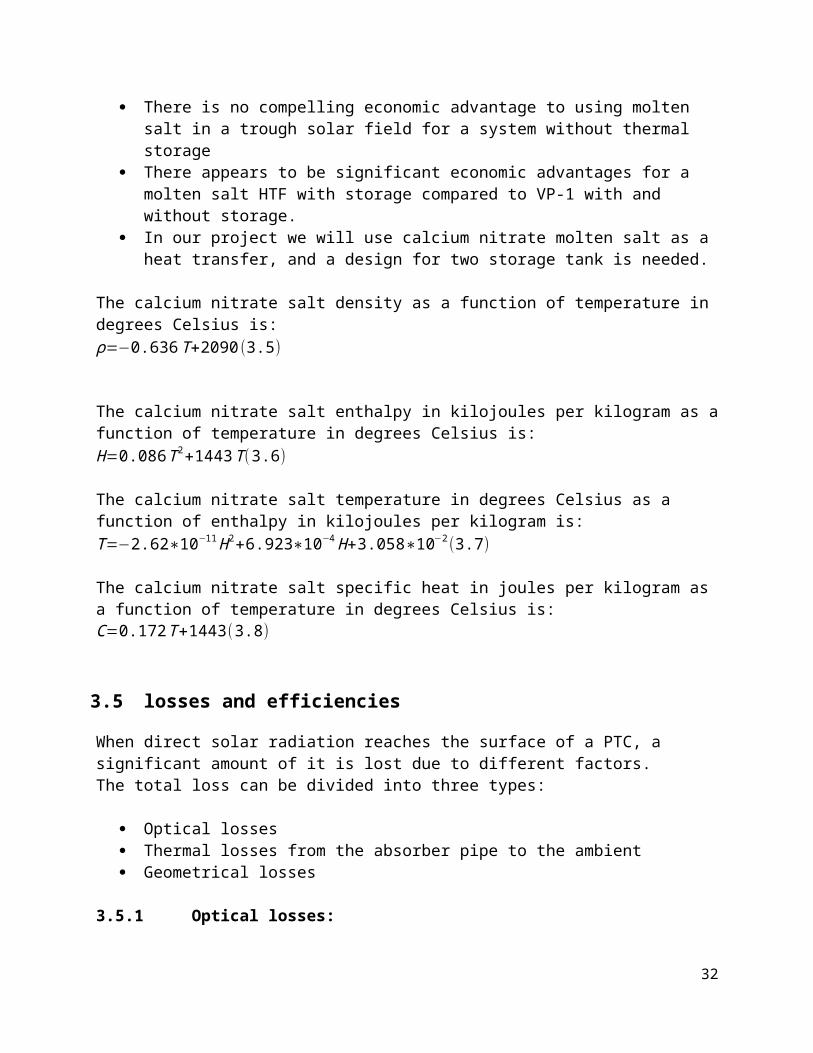
In our project we will use calcium nitrate molten salt as a heat transfer, and a design for two storage tank is needed.
The calcium nitrate salt density as a function of temperature in degrees Celsius is:ρ=−0.636T+2090(3.5)
The calcium nitrate salt enthalpy in kilojoules per kilogram as a function of temperature in degrees Celsius is:H=0.086T2+1443T (3.6)
The calcium nitrate salt temperature in degrees Celsius as a function of enthalpy in kilojoules per kilogram is:T=−2.62∗10−11 H 2+6.923∗10−4 H+3.058∗10−2(3.7)
24

The calcium nitrate salt specific heat in joules per kilogram as a function of temperature in degrees Celsius is:C=0.172T+1443 (3.8)
3.5 losses and efficiencies
When direct solar radiation reaches the surface of a PTC, a significant amount of it is lost due to different factors.The total loss can be divided into three types:
Optical losses Thermal losses from the absorber pipe to the ambient Geometrical losses
3.5.1 Optical losses:
The optical losses are summarized in figure 3.4.
25
Direct solar radiation
Steel absorber pipe(with absorptivity α)
Absorber pipe glass cover(with a transmissivity τ)
Parabolic trough reflector(with reflectivity ρ)(intercept factor Ύ)

Figure 3.4: optical losses in a PTC
Optical losses are divided into several losses which are: reflectivity intercept factor
transmissivity absorptivity
Reflectivity ( ρ ):
When a direct solar radiation hits the surface of a parabolic trough, a part of it is absorbed by the parabola, while the other part is reflected towards the receiver tube. The higher the reflectivity ρ of the material, the better it is. There are several types of reflectors in which we will mention silvered glass mirror having a reflectivity 0.93. When washing the mirrors, their reflectivity continuously decreases as dirt accumulates until the next washing. Usually, they are washed when their reflectivity is about 0.9.
Intercept factor ( Ύ ):
A parabolic trough as seen in the drawings has its parabolic shape perfectly in theory, but in reality, there is no such thing as a parabola even with the highest industrial technologies. This leads to the existence of an intercept factor which means that a fraction of the direct solar radiation will not reach the glass cover of the absorber tube. This intercept factor Ύ is typically 0.95 for a collector properly assembled.
Transmissivity (τ):
The metal absorber tube is placed inside an outer glass tube in order to increase the amount of absorbed energy and reduce thermal losses. A fraction of the direct solar radiation reflected by the mirrors and reaching the glass cover of the absorber pipe is not able to pass through it. The ratio between the radiation passing through the glass tube and the total incident radiation on it, gives transmissivity, τ, which is typically τ=0.93.
Absorptivity ( α ):
This parameter indicates the amount of energy absorbed by the steel absorber pipe, compared with the total radiation reaching the outer wall of the steel pipe. This parameter is typically 0.95 for receiver pipes with a cermet coating, whereas it is slightly lower for pipes coated with black nickel or chrome.
26

Multiplication of these four parameters (reflectivity, intercept factor, glass transmissivity, and absorptivity of the steel pipe) when the incidence angle on the aperture plane is 0˚ gives what is called the peak optical efficiency of the PTC, ηoptical,0˚ :
ηoptical ,0˚=ρ∗Ύ∗τ∗α (3.9)
ηoptical,0˚ is usually in the range of 0.70–0.76 for clean, good-quality PTCs.
3.5.2 Thermal losses:
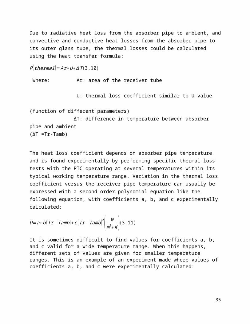
Due to radiative heat loss from the absorber pipe to ambient, and convective and conductive heat losses from the absorber pipe to its outer glass tube, the thermal losses could be calculated using the heat transfer formula:
P ( thermal )=Ar∗U∗∆T (3.10)
Where: Ar: area of the receiver tube U: thermal loss coefficient similar to U-value
(function of different parameters) ∆T: difference in temperature
between absorber pipe and ambient (∆T =Tr-Tamb)
The heat loss coefficient depends on absorber pipe temperature and is found experimentally by performing specific thermal loss tests with the PTC operating at several temperatures within its typical working temperature range. Variation in the thermal loss coefficient versus the receiver pipe temperature can usually be expressed with a second-order polynomial equation like the following equation, with coefficients a, b, and c experimentally calculated:
U=a+b (Tr−Tamb )+c (Tr−Tamb )2( W
m2∗K )(3.11)
It is sometimes difficult to find values for coefficients a, b, and c valid for a wide temperature range. When this happens, different sets of values are given for smaller temperature ranges. This is an example of an experiment made where values of coefficients a, b, and c were experimentally calculated:
27

Table 3.6: Values of coefficients a, b and c for a LS-3 collector [12]
3.5.3 Geometrical losses:
In reality, optical losses are affected by another parameter, called geometrical because of its dependence on earth’s position, and site’s position on the earth. To know more about geometrical losses, figure 3.5 shows that a portion of direct solar radiation does not reach the receiver. This portion of solar radiation is the geometrical losses. These losses are quantified by a factor called incidence angle modifier K (φ) due to its dependence on the incidence angle that varies during every moment of the year. The incidence angle is the angle between the normal and the sun’s radiation vector. So we must define solar angles.
Figure 3.5: Geometrical losses at the end of a collector [12]
3.6 SOLAR ANGLES:
The earth revolves once each day around an axis that passes through the North and South poles. That axis is tilted 23.44o with respect to the orbital plane of the earth around the sun, as shown in figure 3.6. The tilt of the earth’s axis is called the declination angle. It’s the reason that day length changes as the earth makes its annual orbit around the sun. It also significantly affects the intensity of solar radiation striking a fixed surface at any location on earth. We observe this effect as a change in the sun’s path across the sky, as seen in figure 3.7. The sun’s
28

position in the sky can be precisely described using two simultaneously measured angles. The solar altitude angle is measured from a horizontal surface up to the center of the sun. The solar azimuth angle is measured starting from true north (0 o) in a clockwise direction (i.e., true south would have a solar azimuth of 180 o). These angles vary continuously as the sun moves across the sky. At any given time they are also different at different latitudes and longitudes. These angles have been precisely measured, and when needed, can be calculated for any time and location on earth.
Figure 3.6: Earth yearly orbit around the sun [13]
29

Figure 3.7: Azimuth and altitude angle. [13]
The incidence angle depends on the PTC orientation and sun position which can be easily calculated by equation 3.12 for horizontal north south orientation and equation 3.13 for east west orientation.
φ=cos−1 √1−¿¿¿¿
φ=cos−1 √1−¿¿¿¿
Where AZI: azimuth angle ALT: sun elevation angle
The incidence angle modifier, which directly depends on the incidence angle, is usually given by a polynomial equation so that it is equal to 0 for φ =90o, and equal to 1 for φ =0o. Therefore, for instance, the incidence angle modifier for an LS-3 collector is given by: [12]
K (φ )=1−2.23073 E−4∗φ−1.1 E−4∗φ2+3.18596 E−6∗φ3−4.85509 E−8∗φ4(3.14) (0<φ<80 )
K (φ )=(85o<φ<90o)
30

3.7 Efficiencies
The efficiencies: global efficiency (ηglobal), peak optical efficiency(ηoptical,0o), and thermal
efficiency(ηth), without forgetting the parameter K(φ) are used to describe the performance of a PTC.A fraction of the energy flux incident on the collector is lost due to the optical losses, while another fraction is lost because of an incidence angle φ>0, which is taken into account by the incidence angle modifier, K(φ)). The remaining PTC losses are thermal losses at the absorber tube. Figure 3.8 is a simple diagram that explains what’s happening.
Figure 3.8: PTC efficiencies and losses
Let’s explain the above mentioned terms:ηoptical,0
o considers all optical losses that occur with an incidence angle of φ =0o (reflectivity of the
mirrors, transmissibility of the glass tube, absorptivity of the steel absorber pipe and the intercept factor). K(φ), incidence angle modifier, considers all optical and geometrical losses that occur in the PTC because the incidence angle is greater than 0o . Thermal efficiency, ηth, includes all absorber tube heat losses from conduction, radiation, and convection. Global efficiency, ηglobal, includes: optical, geometrical, and heat losses and can be calculated using the following formula:
η ( global )=η (optical ) K (φ )η ( th )(3.15) The global efficiency can be calculated in another method using the figure above where the global efficiency is the ratio of the output power over the solar energy flux on the collector.
η ( global )= P ( HTF )P (sun→collector )
(3.16)
31
P(suncollector) P(collectorfluid)
P(optical,Ф=0)P(optical,Ф>0)P(collectorambient)
ηoptical,0o K(φ) ηth
ηglobal

P (sun→collector )=E∗Ac∗cosφ (3.17)
P ( HTF )=P (sun→collector )∗η (optical )∗K (φ )−P (thermal )(3.18)
Where:
P(HTF): power transferred to the fluid(vp1 oil, molten salt,.....) P(suncollector):Power transferred from the sun to the collector
E:direct solar irradiance Ac: collector aperture area φ: incidence angle P(thermal): thermal loss η(optical): optical efficiency
η(global): global efficiency
3.8 Fluid pump:
The fluid pump, which is in our project a molten salt pump, is the heart of all the system due to the fact that the whole circuit will not operate satisfactorily if the pump does not function properly, so we should select the type of pump that will best meet all of the criteria for a successful high temperature molten salt system. Meeting the flow and head demands for a given system is a very small portion of understanding the specifications for a high temperature pumping system. From a design standpoint, these pumps require simplicity, ruggedness, and flexibility to meet longevity in life. Everything, from how the pump is installed to the maintenance that will be required, must be evaluated before purchasing it. Understanding the total system requirements will ensure a safe and long life of a molten salt pump.
3.8.1 Materials and Temperatures:
The starting point for selecting the materials of construction used for a molten salt pump is knowing the temperature. The operating temperature range for molten salt is between 238oC and 1200oC, 238 being the melting point. The molten salt will decompose at a certain temperature so it is necessary to know the chemistry of the salt being used. As well known, temperature weakens the strength of all materials, so the correct materials and designs are reviewed together. For selecting a pump, one should understand the relationship between materials being used and the design. Either the materials can be used to compensate for weaker designs, or the design can compensate for weaknesses in the materials due to high temperatures. The length of the pump and the operating temperature of the molten salt greatly affect the basic design and material selection of the pump. It is dangerous to select a material that falls into the marginal range or at the extreme high end of the temperature range.
32
High temperatures and basic materials can be divided into four major categories as shown in the following table:
Temperature
240-350 deg C
350-600 deg C
700-930 deg C
930-1100 deg C
Basic Materials
Carbon Steel 316, 321, 347SS
600,625 Inconel
TZM Moly.
304,316 SS Haynes 242 Haynes 263 Waspaloy718 Inconel Haynes 25,
188Haynes 214
Table 3.7: materials to be used according to the temperature range [14]
Before selecting a material, the correlation between the type of salt, temperature range or ranges, velocities within the pump volute and discharge, thermal expansion of the pump shaft, column and discharge assemblies, and mounting arrangement of the pump must be evaluated. The type of salts used in molten salt applications varies widely, from simple compound salts like sodium nitrates and potassium nitrates to blended complexes, such as fluoride based salts like FLiNaK. Understanding their melting points, decomposition temperatures, corrosion characteristics, need for agitation, fluid density at different temperatures and freezing points all help in selecting the proper materials. Temperature ranges that vary can cause distortion and binding in the rotating elements of the pump. For this reason, calculations of each range must be performed to determine the thermal expansion effects on the pump’s rotating assembly and stationary components to ensure the proper materials are used in case these temperature changes occur. The thermal expansion of the rotating assembly and stationary components of the pump must be matched to prevent distortion and binding of the rotating assembly.
3.8.2 Standard High Temperature Pump Designs:When dealing with high temperature molten salt applications, pumps can be categorized into four different styles which are explained in table 4.4.
TemperatureRanges
240-350 oC 350-600 oC 600-930 oC 930-1100 oC
Vertical Cantilever
Setting: 2mMed. FlowMed. HeadDesign: Std.
Setting: 2mMed. FlowMed. HeadDesign: Mod. Std
Setting: 1mMed. FlowMed. HeadDesign: Mod.
Setting: .5mLow FlowLow HeadDesign: Custom
Vertical Setting: 3mHigh/Med. FlowHigh/Med. HeadDesign: Std.
Setting: 3mHigh/Med. FlowHigh/Med. HeadDesign: Mod. Std
Setting: 2mMed. FlowMed. HeadDesign: Mod.
Setting: 1.5mMed. FlowMed. HeadDesign: Custom
Vertical Setting: 20m Setting: 18m Setting: 15m Consult
33

SubmergedBearing
High/Med. FlowHigh/Med. HeadDesign: Custom
High/Med. FlowHigh/Med. HeadDesign: Custom
Med. FlowMed. HeadDesign: Custom
Factory
Axial FlowPropeller
Setting: 4mHigh FlowLow HeadDesign: Custom
Setting: 3mHigh FlowLow HeadDesign: Custom
N/A N/A
Table 3.8: different types of pumps [14]
Vertical cantilever pumps offer many different features, such as several types of mounting arrangements. System designers have great flexibility in tank mounting, as well as mounting the pump outside of the tank. Vertical cantilever pumps have no bearings below the main mounting plate. Cantilever pumps only offer single volute designs. The disassembly of a vertical cantilever pump is the easiest of all four designs.Vertical pumps can be single stage or multi-stage wet end designs. Applications requiring high heads will use multi-staged wet end. Multi-staged wet end designs are custom manufactured for molten salt applications. These pumps have a lower radial bearing. They also have several mounting arrangements, both inside the tank and outside of the tank. Vertical pumps can offer multi stage volutes as an option. They have longer settings than the cantilever, but are more difficult to disassemble.Vertical submerged bearing pumps offer the longest design. They can only be mounted in the tank. Vertical submerged bearing pumps can offer multi-staged volutes. These pumps are the most difficult to disassemble.Axial flow pumps are special in design. Their applications are limited to low heads and high flows. Chemical reactors are one of the main applications for this type of pump. Their special design permits the rotating assembly to be removed from the pump shell without removing the suction and discharge piping. Axial flow pumps can only be mounted with the shaft in a vertical up position. The disassembly of this pump makes it one of the easiest pumps to rebuild.
3.8.3 Mounting and Sealing Molten Salt Pumps:
Understanding how to seal a molten salt pump to either a tank flange or a structure mounted above the tank is very critical for several reasons:First, because this seal area becomes part of the cool down transition section of the pump, it can grow into a major problem if not designed properly. Molten salt will climb the shaft and work its way into this seal area, solidifying and freezing up the rotating assembly if this area is too cool, or spraying dangerous molten salt outside of the tank to create an unsafe situation if it is too hot. This area can be 4-in to 6-in in long for tank mounted pumps, and as much as 4-ft to10-ft long for pumps mounted on structures above the tank. The shaft must be cooled down before the heat reaches the main thrust bearings. This seal area is the first cooling zone, but it must maintain a temperature just above the melting point of the salt. If molten salt is not stopped from migrating up the shaft prior to the first cooling zone, major failures can occur. The
34

use of salt flingers and a counter flow screw machined into the main shaft will reduce the salt migration up the shaft. Based on the shaft speed and liquid levels in the tank, a secondary screw may be required. The size and design of the screws and flingers will vary based upon the temperatures and type of salt being used. In the second cooling zone, just above the seal area, heat fans are used to reduce the shaft temperature to 65oC before reaching the thrust bearings. The design of this area may require external fans for cooling the shaft if the pump sets idle for long periods of time.For our CSP project, the temperature difference of the molten salt between the inlet and outlet of the heat exchanger is 200oC with an inlet of 500 oC and outlet of 300 oC, so the temperature entering the molten salt pump is 300 oC which according to table 3.8 fits into the category of 240-350 oC. We still need to decide which type of pump we should choose. Axial flow propeller seems to be the best to choose since one of its characteristics is low head and the other is high flow.
3.9 Tracking system:
Since CSP collectors works only on direct normal radiation, a sun tracking system is a must. In our case, we are studying PTC, so all we need is a single axis tracking system unlike parabolic dish. The collector rotation around its axis requires a drive unit, one drive unit is usually sufficient for several collectors connected in series, but the type of the drive depends on the scale of collectors. An electric motor with a gear box for small collectors (Ac < 100m2) and a hydraulic drive unit for large collectors.
P.S:
1- The axis of rotation is located at the collector center of mass to minimize the required tracking power.
2- Wind loads condition must be taken into consideration in designing the tracking drive
system in a way that keeps a high concentration efficiency. A normal operation occurs at a wind speed under 7m/s , the concentration efficiency decrease under wind speed between 7 and 14 m/s, and the drive must be able to take the collector to safe positions for a wind speed more than 14 m/s and to rest position for a wind speed exceeding 21m/s.
The drive system is commanded by a control unit in order to track the sun. Since in chapter 4 solar angle section, we saw that we can estimate the sun path during the entire year using azimuth and elevation angles in any location on earth:
35
1- The first type of control unit is based on astronomical algorithms that calculate these angles using very accurate mathematical algorithms.
2- The second type of control unit is called shadow band tracker, it is mounted on the parabolic concentrator and face the sun when the collector is in perfect tracking. Two photo-sensors, one on each side of a separating shadow wall detect the sun’s position. When the collector is correctly pointed the shadow wall shades both sensors equally and their electric output signals are identical.
3- The third type is the flux line tracker; it is mounted on the receiver tube where two sensors are placed on both sides to detect the concentrated flux reaching the tube. The collector is correctly pointed when both sensors are equally illuminated and their electrical signals are the same magnitude.
3.10 Thermal Storage Systems for Concentrating Solar PowerOne challenge facing the widespread use of solar energy is reduced or curtailed energy production when the sun sets or is blocked by clouds. Thermal energy storage provides a workable solution to this challenge.
In a concentrating solar power (CSP) system, the sun's rays are reflected onto a receiver, which creates heat that is used to generate electricity. If the receiver contains oil or molten salt as the heat-transfer medium, then the thermal energy can be stored for later use. This enables CSP systems to be cost-competitive options for providing clean, renewable energy.
Several thermal energy storage technologies have been tested and implemented since 1985. These include the two-tank direct system, two-tank indirect system, and single-tank thermocline system.
36

3.10.1 Two-Tank Direct System
Figure 3.9: Two-tank direct storage system [15]Solar thermal energy in this system is stored in the same fluid used to collect it. The fluid is stored in two tanks—one at high temperature and the other at low temperature. Fluid from the low-temperature tank flows through the solar collector or receiver, where solar energy heats it to a high temperature and it then flows to the high-temperature tank for storage. Fluid from the high-temperature tank flows through a heat exchanger, where it generates steam for electricity production. The fluid exits the heat exchanger at a low temperature and returns to the low-temperature tank.Two-tank direct storage was used in early parabolic trough power plants (such as Solar Electric Generating Station I) and at the Solar Two power tower in California. The trough plants used mineral oil as the heat-transfer and storage fluid; Solar Two used molten salt.
3.10.2 Two-Tank Indirect System
Figure 3.10: Two-Tank indirect storage system [15]
Two-tank indirect systems function in the same way as two-tank direct systems, except different fluids are used as the heat-transfer and storage fluids. This system is used in plants in which the heat-transfer fluid is too expensive or not suited for use as the storage fluid.
37

The storage fluid from the low-temperature tank flows through an extra heat exchanger, where it is heated by the high-temperature heat-transfer fluid. The high-temperature storage fluid then flows back to the high-temperature storage tank. The fluid exits this heat exchanger at a low temperature and returns to the solar collector or receiver, where it is heated back to a high temperature. Storage fluid from the high-temperature tank is used to generate steam in the same manner as the two-tank direct system. The indirect system requires an extra heat exchanger, which adds cost to the system. This system will be used in many of the parabolic power plants in Spain and has also been proposed for several U.S. parabolic plants. The plants will use organic oil as the heat-transfer fluid and molten salt as the storage fluid.
3.10.3 Single-Tank Thermocline System
Figure 3.11: A single-tank themrocline thermal energy storage sytem. [16]
Single-tank thermocline systems store thermal energy in a solid medium—most commonly, silica sand—located in a single tank. At any time during operation, a portion of the medium is at high temperature, and a portion is at low temperature. The hot- and cold-temperature regions are separated by a temperature gradient or thermocline. High-temperature heat-transfer fluid flows into the top of the thermocline and exits the bottom at low temperature. This process moves the thermocline downward and adds thermal energy to the system for storage. Reversing the flow moves the thermocline upward and removes thermal energy from the system to generate steam and electricity. Buoyancy effects create thermal stratification of the fluid within the tank, which helps to stabilize and maintain the thermocline. Using a solid storage medium and only needing one tank reduces the cost of this system relative to two-tank systems. This system was demonstrated at the Solar One power tower, where steam was used as the heat-transfer fluid and mineral oil was used as the storage fluid
38

4 Industrial Process
Figure 4.1: schematic of a solar field linked to the industrial process [12]
As shown in the figure above, the rankine cycle consists of a solar field in which water is superheated and an industrial process. As in a conventional steam cycle, in which water is superheated within the process of burning fossil fuel, the industrial process consists of a steam turbine, condenser (heat exchanger), and a cooling tower to cool the condenser.
4.1 Basic Process and Components:
The thermodynamic cycle for the steam turbine is the Rankine cycle. The cycle is the basis for conventional power generating stations and consists of a heat source (heat exchanger that takes its heat from the solar feed instead of fuel boiler) that converts water to high pressure steam. In the steam cycle, water is first pumped to elevated pressure, which is medium to high pressure depending on the size of the unit and the temperature to which the steam is eventually heated. It is then heated to the boiling temperature corresponding to the pressure, boiled (heated from liquid to vapor), and then most frequently superheated (heated to a temperature above that of boiling). The pressurized steam is expanded to lower pressure in a multistage turbine, then exhausted either to a condenser at vacuum conditions or into an intermediate temperature steam distribution system that delivers the steam to the industrial or commercial application. The condensate from the condenser or from the industrial steam utilization system is returned to the feedwater pump for continuation of the cycle.
39

Primary components of a steam power plant are shown in figure
Figure 4.3: Steam power plant cycle
How the cycle works?
Rankine cycle with superheatProcess 1-2: The working fluid is pumped from low to high pressure.Process 2-3: The high pressure liquid enters a boiler where it is heated at constant pressure by an external heat source to become a dry saturated vapor.Process 3-3': The vapour is superheated.Process 3-4 and 3'-4': The dry saturated vapor expands through a turbine, generating power. This decreases the temperature and pressure of the vapor, and some condensation may occur.Process 4-1: The wet vapor then enters a condenser where it is condensed at a constant pressure to become a saturated liquid.
40

Figure 4.4: T-S diagram for steam generation
4.2 Steam Turbine:
Steam turbines are one of the most versatile and oldest prime mover technologies used to drive a generator or mechanical machinery. Most of the electricity in the United States is generated by conventional steam turbine power plants. The capacity of steam turbines can range from a fractional horsepower to more than 1,300 MW for large utility power plants. Unlike gas turbine and reciprocating engine CHP (combined heat and power) systems where heat is a byproduct of power generation, steam turbines normally generate electricity as a byproduct of heat (steam) generation. A steam turbine is captive to a separate heat source and does not directly convert fuel to electric energy. The energy is transferred from the boiler to the turbine through high pressure steam that in turn powers the turbine and generator. This separation of functions enables steam turbines to operate with an enormous variety of fuels, varying from clean natural gas to solid waste, including all types of coal, wood, wood waste, and agricultural byproducts (sugar cane bagasse, fruit pits and rice hulls). In CHP applications, steam at lower pressure is extracted from the steam turbine and used directly in a process or for district heating, or it can be converted to other forms of thermal energy including hot or chilled water.
41

Steam turbines offer a wide array of designs and complexity to match the desired application and/or performance specifications. In utility applications, maximizing efficiency of the power plant is crucial for economic reasons. Steam turbines for utility service may have several pressure casings and elaborate design features. For industrial applications, steam turbines are generally of single casing design, single or multi-staged and less complicated for reliability and cost reasons.
Figure 4.2: Steam Turbine
4.2.1 Types of Steam Turbines:
The primary type of turbine used for central power generation is the condensing turbine. These power-only utility turbines exhaust directly to condensers that maintain vacuum conditions at the discharge of the turbine. An array of tubes, cooled by river, lake or cooling tower water, condenses the steam into (liquid) water. The condenser vacuum is achieved by cooling with the near ambient-temperature water, thus causing condensation of the steam turbine exhaust in the condenser. A small amount of air is known to leak into the system because the condenser operates below atmospheric pressure, therefore, a relatively small compressor is used to remove non-condensable gases from the
42

condenser. Non-condensable gases include both air and a small amount of hydrogen, which is the corrosion byproduct of the water-iron reaction. The condensing turbine process results in maximum power and electrical generation efficiency. l. The power output of condensing turbines is very sensitive to ambient conditions.
Steam turbines used for CHP can be classified into two main types: non-condensing and extraction.
Non-Condensing (Back-pressure) Turbine:
The non-condensing turbine (also referred to as a back-pressure turbine) exhausts its entire flow of steam to the industrial process or facility steam mains at conditions close to the process heat requirements, as shown in Figure 4.5 Usually, the steam sent into the mains is not much above saturation temperature.
Figure 4.5: non-condensing turbine (back-pressure turbine)
The term "back-pressure" refers to turbines that exhaust steam at atmospheric pressures and above. The discharge pressure is established by the specific CHP application. 50, 150 and 250 psig are the most typical pressure levels for steam distribution systems. The lower pressures are most often used in small and large district heating systems, and the higher pressures most often
43

used in supplying steam to industrial processes. Industrial processes often include further expansion for mechanical drives, using small steam turbines for driving heavy equipment that is intended to run continuously for very long periods. Significant power generation capability is sacrificed when steam is used at appreciable pressure rather than being expanded to vacuum in a condenser. Discharging steam into a steam distribution system at 150 psig can sacrifice slightly more than half the power that could be generated when the inlet steam conditions are 750 psig and 800° F, typical of small steam turbine systems.
Extraction Turbine:
The extraction turbine has opening(s) in its casing for extraction of a portion of the steam at some intermediate pressure. The extracted steam may be use for process purposes in a CHP facility, or for feedwater heating as is the case in most utility power plants. The rest of the steam is condensed, as illustrated in Figure 4.6.
Figure 4.6: extraction turbine
The steam extraction pressure may or may not be automatically regulated depending on the turbine design. Regulated extraction permits more steam to flow through the turbine to generate additional electricity during periods of low thermal demand by the CHP system. In utility type steam turbines, there may be several extraction points, each at a different pressure corresponding to a different temperature at which heat is needed in the thermodynamic cycle.
44

The facility's specific needs for steam and power over time determine the extent to which steam in an extraction turbine will be extracted for use in the process, or be expanded to vacuum conditions and condensed in a condenser. In large, often complex, industrial plants, additional steam may be admitted (flows into the casing and increases the flow in the steam path) to the steam turbine. Often this happens when multiple boilers are used at different pressure, because of their historical existence. These steam turbines are referred to as admission turbines. At steam extraction and admission locations there are usually steam flow control valves that add to the steam and control system cost. When steam is expanded through a very high pressure ratio, as in utility and large industrial steam systems, the steam can begin to condense in the turbine when the temperature of the steam drops below the saturation temperature at that pressure. If water drops were allowed to form in the turbine, blade erosion would occur when the drops impact on the blades. At this point in the expansion the steam is sometimes returned to the boiler and reheated to high temperature and then returned to the turbine for further (safe) expansion. In a few very large, very high pressure, utility steam systems double reheat systems are installed. Between power (only) output of a condensing steam turbine and the power and steam combination of a back-pressure steam turbine, essentially any ratio of power to heat output can be supplied to a facility. Back-pressure steam turbines can be obtained with a variety of back- pressures controls, further increasing the variability of the power-to-heat ratio.
4.3 Heat Exchangers:
Heat exchangers use a thermally conducting element usually in the form of a tube or plate to separate two fluids, such that one can transfer thermal energy to the other. Home heating systems use a heat exchanger to transfer combustion gas heat to water or air, which is circulated through the house. Power plants use locally available water or ambient air in quite large heat exchangers to condense steam from the turbines. Anyone who wants to use a heat exchanger should understand the thermodynamic and transport properties of fluids and combine these properties to some simple calculations to define a specific heat-transfer problem and select an appropriate heat exchanger. The way heat gets transferred from one fluid to another depends on the physical characteristics of the fluids involved, especially their density, specific heat, thermal conductivity, and dynamic viscosity. A brief definition of each of these properties would be in the following way. Density(ρ) is a fluid’s mass per unit volume, measured in Kg/m3. Specific heat(C or Cp for gases) is the amount of heat required to raise the temperature of one unit of fluid mass by one degree. Its unit is J/Kg˚C. Specific heat relates the quantity of transferred heat to the temperature change of the fluid while passing through the heat exchanger. Thermal conductivity (k) represents the ability of a fluid to conduct heat (measured in W/m˚C).
45

Dynamic viscosity (μ) indicates a fluid’s resistance to flow. A fluid with high dynamic viscosity produces a high pressure loss because of the shear resistance, primarily along the heat exchanger surfaces. Its unit is kg/ms. Inside a heat exchanger, the fluid flow is either turbulent or laminar. Turbulent flow produces better heat transfer, because it mixes the fluid. Laminar-flow heat transfer relies entirely on the thermal conductivity of the fluid to transfer heat from inside a stream to a heat exchanger wall. An exchanger’s fluid flow can be determined from its Reynolds number (NRe):
N (ℜ )=ρ∗V∗D
μ(4.1)
Where ρ:density V:flow velocity D:diameter of the tube in which the fluid flows
μ:dynamic viscosity
The characteristics of fluids contribute to a fundamental property of heat exchangers (the heat transfer rate ∂). The heat transferred to the colder fluid must equal that transferred from the hotter fluid, according to the following equation:
∂=[m∗Cp∗(Tout−Tin ) ]cold (4.2)
¿−[m∗Cp∗(Tout−Tin ) ]hot (4.3)
Where: ∂: heat transferred per unit time
m: mass flow per unit time
Cp: specific heat
An exchanger’s effectiveness (ε) is the ratio of the actual heat transferred to the heat that could be transferred by an exchanger of infinite size. Effectiveness is the best way to compare different types of heat exchangers. The heat balance equation can be applied to this problem:
ε=(mCp )hot (Tin−Tout )hot
(mCp ) min (Tinhot−Tin cold )( 4.4 )= (mCp )cold (Tout−Tin )cold
(mCp ) min (Tinhot−Tin cold )(4.5)
4.3.1 Exchanger Equation:
46

The heat transfer rate (∂) of a given heat exchanger depends on its design and te properties of the two fluid streams. The characteristic can be defined as:
∂=U∗A∗∆T (4.6)
Where:
U: overall heat transfer coefficient, or the ability to transfer heat between the fluid streams.
A: heat transfer area of the heat exchanger.( total area of the wall that separates the two fluids)
∆T: average temperature difference between the two fluid streams over the length of heat exchanger
In order to predict the heat exchanger’s performance, the overall heat transfer coefficient U and the area A should be calculated. The inlet temperatures of the two streams can be measured, which leaves three unknowns: the two exit temperatures and the heat transfer rate. These unknowns can be determined using the following three equations:
∂=U∗A∗(Tinhot−Tout cold )+ (Tout hot−Tin cold )
2(4.7)
¿ [m∗Cp∗(Tout−Tin ) ] cold(4.8)
¿−[m∗Cp∗(Tout−Tin ) ]hot (4.9)
4.3.2 Types of Exchangers:
There are many types and sizes of heat exchangers:
Coil heat exchangers:
Coil heat exchangers have a long, small diameter tube placed concentrically within a larger tube, the combined tubes being wound or bent in a helix. One fluid passes through the inner tube, and the other fluid passes through the outer tube. This type of heat exchanger is capable of handling high pressures and wide temperature differences. These exchangers provide poor thermal performance because of a small heat transfer area. A coil heat exchanger may be the best choice for low flow situations, because the single tube passage creates higher flow velocity and a higher Reynolds number. These exchangers can be used to condense high temperature steam samples.
47

Figure 4.7: Coil heat exchangers
Plate heat exchangers:Plate heat exchangers consist of a stack of parallel thin plates that lie between heavy end plates. Each fluid stream passes alternately between adjoining plates in the stack, exchanging heat through the plates. The plates are corrugated for strength and to enhance heat transfer by directing the flow and increasing turbulence. These exchangers have high heat transfer coefficients and area, the pressure drop is also typically low, and they often provide very high effectiveness. However, they have relatively low pressure capability.
Figure 4.8: Plate heat exchanger
48

Shell and tube heat exchangers:Shell and tube heat exchangers consist of a bundle of parallel tubes that provide the heat transfer surface separating the two fluid streams. The tube side fluid passes axially through the inside of the tubes; the shell side fluid passes over the outside of the tubes. Baffles external and perpendicular to the tubes direct the flow across the tubes and provide tube support. Tubesheets seal the ends of the tubes, ensuring separation of the two streams. The process fluid is usually placed inside the tubes for ease of cleaning or to take advantage of the higher pressure capability inside the tubes. The thermal performance of such an exchanger usually surpasses a coil type but is less than a plate type. Pressure capability of shell and tube exchangers is generally higher than a plate type but lower than a coil type.
Figure 4.9: Shell and tube heat exchanger
49

Technical Tips:
Consider heat exchangers early in system design. Avoid being overly safe in specifying performance criteria. Consider increasing pumping power rather than increasing an exchanger’s size. Higher
velocity flow can produce or increase turbulence, which leads to an increased pressure drop and the need for more pumping power.
Specify the smallest possible tubing for tube type heat exchangers, because it gives the maximum thermal performance with the minimum volume. However, be aware of the effects of fouling or particulates that may clog small tubes.
Be aware of fluid thermal conductivity when specifying the cooling or heating fluid. Water usually works the best.
Consider an exchanger’s lifetime and maintenance requirements. Choose the type and thickness of material that will reduce failure caused by corrosion and erosion.
50

5 Designing an 8.5 Mwe solar thermal power plant
In order to design a solar thermal power plant, an inverse calculation method should be adopted. This means that the given data would be how much electricity is needed to satisfy a certain need; once this given is known, the inverse procedure can start from the steam turbine and end at the sun’s power which will be needed to reflect on the parabolic trough, which is the type of solar field that we have chosen among the several types of solar fields (receiver tower, Fresnel,…..).
Since the electrical power needed is 8.5MWe, the smallest steam turbine that is compatible with such power is Siemens turbine SST-100 with the following specifications:
Condensing pressure= 1 bar (P1=P6=1 bar)
Design working pressure= 65 bar (P4=P5=65 bar)
Inlet design temperature= 480oC (T4=T5=480oC)
8.5MWe is the electrical power output of the alternator, assuming the efficiency of the alternator is 0.9, the mechanical power of the turbine is P= 8.5/0.9=9.444 MW=33998.4MJ/h
51

P5=65 bar Using Mollier diagram h5=807.7 Kcal/kg=3379.4168 KJ/Kg
T5=480oC
P6=1 bar Using Mollier diagram h6=588.46 Kcal/kg=2462.11664 KJ/kg
Isentropic
Assuming the efficiency of the turbine is 0.86 the work of the turbine is Wt=0.86*(h5-h6)
Wt= 788.878 KJ/Kg
The steam flow is: msteam=P/Wt=43097.16 Kg/h
Pump: Assuming P2=73 bar to consume losses in the pipes and pump efficiency of 0.8
Pump work: Wp= v(P2-P1)/0.8
T1=42oC v=0.001009 m3/kg
Wp=9.081 KJ/Kg
Boiler: Qb=h4-h3=3379.4168 KJ/Kg - 171.8 KJ/Kg = 3207.6168 KJ/Kg
Efficiency of the cycle is η=(Wt-Wp)/Qb=0.2431 η increase when the cycle is reheated.
Solar field:
Concentration ratio: C=la/(3.14*d0)= 5760/(70*3.14)=26.2 (equation 3.2)
Assuming desired rim angle=100o
Focal point: f=la/(4*tg(100/2))=1.2083 m (equation 3.3)
Reflectivity: 0.94
Intercept factor: 0.95
Transmissivity of glass tube: 0.93
Absorptivity of absorber: 0.96
Optical efficiency: ηopt=0.96*0.93*0.94*0.95=0.797 (equation 3.9)
Thermal losses:
Since the Heat transfer fluid is molten salt, Tabs=500oC, Tamb=30oC
52
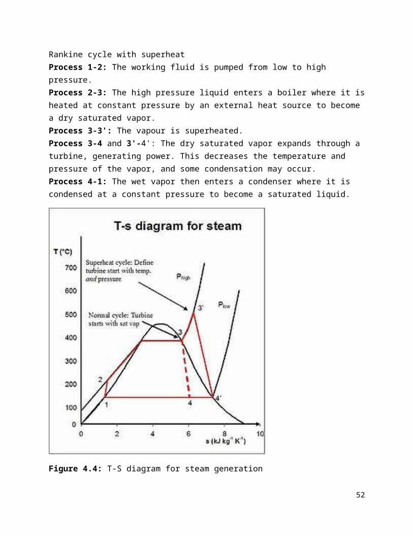
Tabs=500oC lead to: a= 2.895474, b=-0.0164, c=0.000065 (table 3.6)
UL,abs=9.546 W/m2.col.k (equation 3.11)
Pthermal=3946.64 W (equation 3.10)
Geometrical losses:
Assume the designing point in august at 12:00 noon
Lebanon is at 33.5o N and 35.5o E
Direct solar irradiance 800 W/m2
As a result azimuth and elevation angle are respectively 231.6o and 71.7o
Incidence angle is 14.2453o (equation 3. 12)
Geometrical losses factor is 0.98 (equation 3.14)
Heat collected by one concentrator: PHTF= 10670 W (equation 3.18)
Heat exchanger calculation:
T7=300oC => h7=440.64 KJ/Kg (equation 3.)
T8=500oC => h8=743 KJ/Kg (equation 3.)
mHTF =msteam *(h4-h3)/((h8-h7)*ηheat exchanger)= 539158 Kg/h
if N1 is the number of mirrors in a row and N2 is the number of parallel rows then by doing some calculations N1*N2=Pb/PHTF=3607.35
N1=77, N2=47
The distance between two parallel rows must be greater than 17 meters to avoid shading
So the area of the solar field is (77*4)*(47*17)=246092 m2
Conclusion : with a small solar field occupation, 8.5 MWe electrical power is produced freely from the sun. Note that 8.5 MWe is the smallest turbine we have found, with a high condensing pressure and with no reheat cycle, so in other application, more power can be easily achieved even with a small space taken by the solar field.
53

6 Practical study
Once the theoretical study is accomplished, a practical approach can be done using the available material that would help us do a small prototype to make us express our idea in a better way.
First, we should start by setting a list of the materials that should help build the project:
1. Solar field2. Vacuum tube3. Steam engine + alternator
If this project is done on a scale of a city (i,e,250 MW of electricity), more materials would have been used, but since this is a prototype, a simple connection between the upper mentioned materials would be enough to make our point. Let’s start by the explanation of the steps of building our project.
1. Solar field:
A solar field is a large space of collectors used to reflect the sun onto a certain place; in our case, it is a set of parabolic troughs that reflect the sun onto a focal line where a certain heat transfer fluid flows, this set of parabolic troughs is in series and parallel. Our solar field is one parabolic trough of dimensions: aperture length = 1.6 m
length of trough = 2 m
Which means an aperture lengh = 2*1.6 = 3.2 m2
Our parabolic trough has a form of a parabola due to its name. So in order to build it with a
minimum amount of losses, we took the following equation: Y= X2
4∗P
Where P=distance from the origin to the focal point
A set of points has been taken which is shown in the following table: (where P= 30 cm)
54

x y=x^2/(4p)
-8053.3333333
3-75 46.875-60 30
-5020.8333333
3
-4013.3333333
3-30 7.5
-203.33333333
3
-100.83333333
30 0
100.83333333
3
203.33333333
330 7.5
4013.3333333
3
5020.8333333
360 3075 46.875
8053.3333333
3
This table is translated into the following graph:
55

-100 -80 -60 -40 -20 0 20 40 60 80 1000
10
20
30
40
50
60
y=x^2/(4p)
y=x^2/(4p)
According to this graph, we went to a carpenter in order to bring the wood pieces according to the measurements above. So the next step is to build up our chassis using the wood pieces that will be the support of the reflecting material and will give it the parabolic form in the best way in order to minimize as much as we can the heat losses.
2. Vacuum tube:
The vacuum tube is an essential part of the project since all the rays of the sun can come in and cannot escape; therefore, the convective losses are negligible. The vacuum tube we are using has in it a copper tube. Why did we use copper tube? Since we need a temperature above 100 and the classical vacuum tube can’t handle high temperatures, so copper pipes with a black paint on them to absorb the heat will be enough to handle high temperatures. The high transfer fluid (HTF) in our practical case is water. The vacuum tube is open-ended which means that the inlet and outlet of the HTF is at the same end, but the only difference is that steam is generated at the outlet. The copper tube has a U turn due to the fact that the inlet and outlet is at the same place. This picture shows the vacuum tube we used:
56

3. Stean engine+alternator:
An engine in which the energy of hot steam is converted into mechanical power, especially an engine in which the force of expanding steam is used to drive one or more pistons. The source of the steam is typically external to the part of the machine that converts the steam energy into mechanical energy. In our case, the source of the steam is the sun. The selection of the steam engine was a litttle bit difficult. We went online and searched for a small steam engine that should satisfy our work, but the problem was the missing specifications of the steam engine(what temperature and what pressure make this steam engine work). So, we’ve thought of a better way to get this item. If we take an air compressor that is used to blow car wheels, bicycle wheels, basket balls,....., we see that once this air compressor is plugged into a battery, the alternator will rotate thus rotating a gear that has the same axis as the alternator. Then the power is transferred to a bigger gear which will tranform the rotation into translation of a piston that will move up and down to create pressure and finally blow the wheel. Our project has a unique goal: generating electricity, so if a take the same mechanical procedure of this air compressor, but reverse it:: the pressure of the steam will move the piston up and down which will rotate the gear and then the alterantor thus producing a DC voltage. We brought an air compressor and we took the inside of it which includes the above mentioned products. We can put the steam in
57

a small tank with a gate valve at its outlet in order to open it when this tank is fulled with steam. Here is a picture of the air compressor:
Assembly:
58

59

60

Appendix VB ProgrammingThis program is designed to simplify all calculations needed with an easy interface to work with.
The following snap shots will show the steps needed to design a solar thermal power plant.
Step 1: Main interface
In this interface, we can access to all windows needed to complete the calculation, and as shown in the figure, some tabs are unavailable; it means this window is locked until opening a specific window.
61
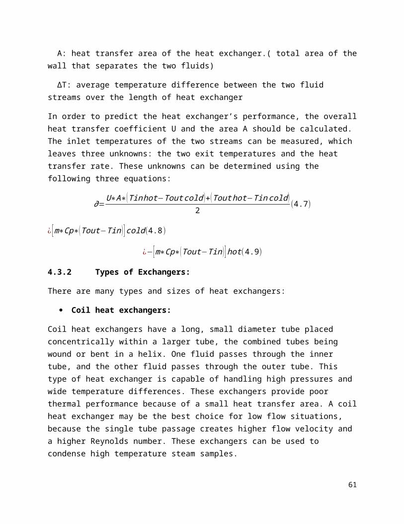
Step 2: collector design
The user enters the receiver pipe diameter and the aperture length in mm in order to get the concentration ratio as an output.
The user enters the rim angle to get the focal distance as an output.
These 2 steps of the design are found in details in section 3.2.
62

Step 3: losses calculation
The user enters the efficiencies due to the optical losses. Much more explanations are found in section 3.5.1.
The user enters the ambient temperature, collector length, and the design temperature for the HTF used. U value and the thermal losses are calculated. More details are given in section 3.5.2.
63

The user enters the altitude and the azimuth angle with the PTC orientation to get the incidence angle and the incidence angle modifier as an output. For more information refer to section 3.5.3
Step 4: Heat collected by the HTF for one concentrator
In this step, the user enters the sun irradiance design value, and after pressing the button ‘calculate’, the program gives the heat collected by one concentrator (1 parabolic mirror).
64

Step 5: HTF proprieties
In this step, the users chooses the type of the heat transfer fluid with its inlet and outlet temperatures.
65

Step 6: steam proprieties
The input in this step constitutes of the steam inlet pressure and temperature. The user also enters the outlet pressure of the condenser and the inlet temperature of the heat exchanger. The output of this step is the enthalpy at the inlet and outlet of the turbine in addition to the enthalpy at the inlet of the heat exchanger and the specific volume at the outlet of the pump.
66

Step7: solar field calculation
Once the electrical power output, turbine efficiency, output pump pressure(head), heat exchanger efficiency, and alternator efficiency are entered by the user, the output will be the work of the turbine and pump, HTF flow, mechanical power output, steam water flow, Q(boiler), P(boiler), cycle efficiency, and the product N1*N2. Then, a set of choices of N1 and N2 will be given in order for the user to choose one.
67

References:
[1] http://www.ourecohouse.info/images/solar-radiation.jpg
[2] Source: GNSED Report on “Renewable Energy Technology Contribution an Barriers to Poverty Alleviation Jordan, Syria and Lebanon”
[3] http://www.psapublishing.com/Solar_Power.pdf
[4]
http://webservices.itcs.umich.edu/drupal/recd/sites/webservices.itcs.umich.edu.drupal .recd/files/ Figure3-2.jpg
[5] http://newenergyportal.files.wordpress.com/2009/12/compact-linear-fresnel-reflector.png?w=472&h=292
[6] http://www.trec-uk.org.uk/press/brussels/prince_hassan_presentation.html
[7] http://www.powerfromthesun.net/Book/chapter08/chapter08.html
[8] http://www.solar-evacuated-tube.com/solar_product_info_276.html
[9] http://pointfocus.com/images/pdfs/saltw-troughs.pdf
[10] http://www.nrel.gov/csp/troughnet/pdfs/40028.pdf
[11] http://pointfocus.com/images/pdfs/saltw-troughs.pdf
[12] Handbook of energy efficiency and renewable energy
[13] http://www.caleffi.us/en_US/caleffi/Details/Magazines/pdf/idronics_3_us.pdf
[14] http://www.pump-zone.com/articles/387.pdf
[15] http://www.opportunityenergy.org/wp-content/uploads/2010/07/molten32.gif
[16] http://www.eere.energy.gov/basics/renewable_energy/images/photo_termocline_test. gif
68

69