Embed Size (px)
Citation preview

IMIA Working Group Paper WG 84 (14)
IMIA Conference Sep. 2014
Solar Thermal Power Plant
Working Group Members: Chair Person: Manuela Baroncini, Corporate Solutions, Swiss Re Contributors: Alberto Mengotti, Mapfre Charlie Richardson, GCube Dan Georgescu, XL José Antonio Otero, RSA Mamoon Alyah, LWS Consulting Miguel Angel Patier, Mapfre Navraj Basra, Infrassure Stephan Heigl, Munich Re Stephen Morris, HSB Engineering Richard Radevsky, Charles Taylor Adjusting (Sponsor)

CONTENTS ACRONYMS ............................................................................................................................... 5 1 EXECUTIVE SUMMARY .................................................................................................. 6 2 INTRODUCTION .............................................................................................................. 8 2.1 Disclaimer ........................................................................................................................ 9
3 HISTORY AND DEVELOPMENT ................................................................................... 10 3.1 Worldwide production and market development ............................................................. 10 3.2 Market Drivers ................................................................................................................ 10 3.3 Economics ...................................................................................................................... 11 3.4 Future developments ...................................................................................................... 13 4 CSP TECHNOLOGIES ................................................................................................... 14 4.1 Main CSP systems components ..................................................................................... 14
4.1.1 Mirror System ...................................................................................................... 14
4.1.2 Heat Transfer Fluid (HTF) System ....................................................................... 14
4.1.3 Heat Exchanger ................................................................................................... 15
4.1.4 Thermal Energy Storage (TES) ............................................................................ 16
4.1.5 Control System .................................................................................................... 16
4.1.6 Power block ......................................................................................................... 17
4.1.7 Balance of plant (BOP) / Auxiliary systems .......................................................... 17 4.2 Main CSP Technologies ................................................................................................. 17
4.2.1 Parabolic Trough (PT) .......................................................................................... 18
4.2.2 Linear Fresnel System (LF) .................................................................................. 19
4.2.3 Solar Tower (ST) ................................................................................................. 20
4.2.4 Stirling Dish System ............................................................................................. 22 4.3 Alternative CSP application: Integrated Solar Combined Cycle ...................................... 24
5 MAIN RISKS IN A CSP PLANT ...................................................................................... 25 5.1 Conventional Risks ......................................................................................................... 25
5.1.1 Project Location ................................................................................................... 27
5.1.2 Mirror System ...................................................................................................... 28
5.1.3 Power Tower........................................................................................................ 31
5.1.4 Heat Transfer Fluid (HTF) System ....................................................................... 34
WG 84 (14) - Solar Thermal Power Plant 2

5.1.5 Thermal Energy Storage (TES) ............................................................................ 35
5.1.6 Heat Exchangers ................................................................................................. 36
5.1.7 Balance of plant (BOP)/Auxiliary Systems ........................................................... 37
5.1.8 Power Block ......................................................................................................... 38
5.1.9 Control System .................................................................................................... 39 5.2 Non-conventional Risks .................................................................................................. 39
5.2.1 Weather risks ....................................................................................................... 40
5.2.2 System efficiency ................................................................................................. 41
5.2.3 Parasitic consumption .......................................................................................... 42
5.2.4 Grid integration .................................................................................................... 42
5.2.5 Regulatory / Institutional risks .............................................................................. 43
5.2.6 Environmental Concerns ...................................................................................... 43 6 RISK MANAGEMENT AND INSURANCE SOLUTIONS ................................................. 44 6.1 Risk Management Process ............................................................................................. 44 6.2 The role of insurers ........................................................................................................ 46 6.3 Insurance products ......................................................................................................... 46
6.3.1 Erection/Construction All Risks Policy (EAR/CAR) ............................................... 46
6.3.2 Delay in Start-up Policy (DSU) ............................................................................. 49
6.3.3 Third party Liability (TPL) ..................................................................................... 51
6.3.4 Operational All Risks (OAR) ................................................................................. 52
6.3.5 Business Interruption (BI)..................................................................................... 53
6.3.6 Cargo and Marine Delay Start-up (MDSU) ........................................................... 53
6.3.7 Warranties Cover ................................................................................................. 55
6.3.8 Liquidated Damages (LD) .................................................................................... 56
6.3.9 Weather Derivative .............................................................................................. 56
6.3.10 Lack of Sun .......................................................................................................... 57
6.3.11 Other relevant insurance products ....................................................................... 58 7 CLAIMS AND LESSONS LEARNT ................................................................................. 59 8 CONCLUSION ............................................................................................................... 63 9 APPENDIX ..................................................................................................................... 64 9.1 Appendix – Direct Normal Irradiance (DNI) ..................................................................... 65
WG 84 (14) - Solar Thermal Power Plant 3

9.2 Appendix - CSP hybrid projects ...................................................................................... 67 9.3 Appendix - CSP technology developments in 2020-2030 ............................................... 68 9.4 Appendix – Spanish Policy ............................................................................................. 70
10 REFERENCES ............................................................................................................... 71 11 EXTERNAL LINKS ......................................................................................................... 73
WG 84 (14) - Solar Thermal Power Plant 4

ACRONYMS
BI Business Interruption
CAR Construction All Risks
CSP Concentrated Solar Power
DNI Direct normal irradiance
DSU Delay in Start-Up
EAR Erection All Risks Policy
FITs Feed in Tariffs
HTF Heat Transfer Fluid
ICOW Increased Cost of Working
LCOE Levelised Cost of Energy
LDs Liquidated Damages
OAR Operational All Risks
OEM Original Equipment Manufacturers
PD Property Damage
PPA Power Purchase Agreement
PT Parabolic Trough
SRSG Solar Receiver Steam Generator
ST Solar Tower
TES Thermal energy storage
PV Photovoltaic
WG 84 (14) - Solar Thermal Power Plant 5

1 EXECUTIVE SUMMARY
Development of Solar Thermal Power:
Compared to other renewable energy technologies, the solar thermal power industry is a relatively new industry with a limited operational experience. The rapid growth over the past few years has led to a fast development in Concentrated Solar Power (CSP) technology and to an increase in the scale and complexity of projects and associated risks. From an International Energy Agency study it is estimated that by 2050 CSP could provide 11.3% of global electricity compared to an estimate of 9.6% from solar power. In the sunniest countries, CSP can be expected to become a competitive source of bulk power in peak and intermediate loads by 2020, and of base-load power by 2025 to 2030. Main Components: CSP plants use large mirror fields - sometimes 100,000 or more mirrors - controlled by sophisticated tracking systems to reflect and concentrate sunlight onto a focal line (e.g. parabolic trough collectors) or a focal point (e.g. solar tower) to heat a fluid and produce the steam that drives a turbine and generates electricity.
Major CSP components include:
- Mirror System - Heat Transfer Fluid (HTF) System - Heat Exchanger - Thermal Energy Storage (TES) - Controls System
In addition to the solar components listed above, plants have many other elements that represent standard technology for generating electricity. These include natural gas boilers, steam turbine, steam generator, condenser, cooling tower, balance of plant and auxiliary systems.
Risk Exposures: Throughout the process of financing, designing, building and operating a CSP plant, it is important to evaluate the various risks for the different parties involved with the project and their ability to manage those risks. This evaluation is part of the risk management process. Insurance is the most common mechanism to transfer risks from the risk owner to third parties (the insurers).
Risk exposures can be categorized under two main headings:
- Conventional Risks: These are risks related to the construction and the operation of a plant including technology risks (i.e. innovative design, scaling up of a design, project execution risks (i.e. lack of experience) and natural perils. They are often the cause of a physical loss or physical damage to the CSP plant which could also affect the revenue of the plant
WG 84 (14) - Solar Thermal Power Plant 6
Insurance for such exposures can be covered under Construction/Erection All Risks, Delay in Start Up, Property Damage, Business Interruption, Third Party Liability, and Marine Cargo
- Non-Conventional Risks: These are risks which affect the CSP plant's revenue, and its
volatility, like the unavailability of the plant due to lack of sun, strong wind, or regulatory / institutional risks, lack of performance, etc.
Through adequate risk transfer insurance solutions, CSP projects could attract new potential investors and developers, and would reduce the barriers to their bankability. At the same time the insurance industry can also provide valuable benefits to the CSP industry through its loss control and risk reduction services (i.e. risks surveys). This paper expands and explains the above main themes and provided examples of claims, main risk exposures and the role of insurers.
WG 84 (14) - Solar Thermal Power Plant 7

2 INTRODUCTION The amount of sun power streaming in as sunlight is roughly 1,000 W per square meter. Getting that sunlight concentrated and making it "work" is a challenge that has intrigued many scientists since Archimedes’ time. Only in recent years, with the evolution of materials and technologies, has it become possible to turn this dream into a reality and to transform the sunlight into something that "works": electricity.
In the last 50 years the solar industry has developed two types of solar technology:
• Solar panel systems, also known as photovoltaic (PV), where the sun's light is converted directly into electricity (out of the scope of this paper)
• Solar thermal power plants, also known as Concentrated Solar Power (CSP) plants, where power is generated the same way as traditional power plants by creating high temperature steam to turn a turbine. However instead of using fossil fuels or nuclear decomposition processes to create the steam, CSP plants use large mirror fields - sometimes 100,000 or more mirrors - controlled by sophisticated tracking systems to reflect and concentrate sunlight onto a focal line (e.g. parabolic trough collectors) or a focal point (e.g. solar tower) to heat a fluid and produce the steam that drives a turbine and generates electricity.
Considering the amount of solar energy that reaches the earth in one hour, which is more than the combined worldwide consumption of energy by human activities in one year, the potential of the solar industry is enormous. In fact a recent study by the International Energy European Solar Thermal Electricity Association suggested that CSP plants could provide up to 25 percent of the world's electricity needs by 2050.
Even though CSP shows a significant potential, the high cost of this technology compared to a conventional coal and gas-based power plant or other alternative energy sources could undermine the growth in actual CSP developments. Hence the primary challenge of the CSP industry is how to improve installation and operating costs, as well as the efficiency of CSP plants to make CSP energy more affordable. This is driving many research efforts into developing new technologies, novel materials, better heat-transfer fluids, lower-cost mirror materials, thermal storage solutions, receivers that can achieve high temperatures, and higher-efficiency heat collectors.
This IMIA paper provides an updated picture of the CSP industry, along with the current status and key trends, comprising a brief description of the four main CSP technologies focusing mainly on:
• Parabolic Troughs (PT): by far the most commonly deployed CSP technology with currently 95.4% worldwide CSP capacity, and
WG 84 (14) - Solar Thermal Power Plant 8

• Solar Tower (ST): the CSP technology which shows the highest potential for growth in the years to come because of its advantage in operating at higher temperatures, and therefore at higher efficiency, and best suitability for heat storage systems implementation.
Even though CSP has experienced a significant growth in recent years, especially with PT and ST technology, it still remains a relatively new industry with limited operational experience in comparison with some other renewable energy technologies.
CSP technology is developing fast to obtain more cost-efficient plants. However any technological improvement could represent a new risk that needs to be carefully evaluated by the various parties involved with the project, whether this be the financiers, the plant operator, the contractors, the designers/engineers, or the insurers.
This IMIA paper aims to offer an effective support to assess the main exposures of a CSP plant by analysing the main CSP risks, sharing lessons learned, and outlining options for managing those risks, including insurance risks transfer solutions.
2.1 Disclaimer This IMIA paper is based on experience observed by the authors in the CSP insurance industry.
The risks described here are not exhaustive and other risks may exist to impact the success of a CSP project which may not be described in this paper.
Should the reader have alternative views on the main risks perceived by the authors, we would welcome the opportunity of further discussion.
WG 84 (14) - Solar Thermal Power Plant 9

3 HISTORY AND DEVELOPMENT
The first commercial CSP plants began operating in California in the period 1984 to 1991, spurred by federal and state tax incentives and mandatory long-term power purchase contracts. A drop in fossil fuel prices then led the federal and state governments to dismantle the policy framework that had supported the advancement of CSP.
In 2006 the market re-emerged in Spain and the United States, again in response to government measures such as feed-in tariffs (Spain) and policies obliging utilities to obtain some share of power from renewable and from large solar in particular.
3.1 Worldwide production and market development
Solar energy has been the fastest-growing energy sector in the last few years, albeit from a very low base. It is expected to reach competitiveness on a large scale in less than ten years – but today most applications require support incentives, the cost of which is a serious concern for some policy makers. Some see solar energy as a boost for economic growth, others as a drag in the aftermath of a global financial crisis and in the context of sovereign debts.
Fig. 1 – On-going CSP targets and plants (operational, under construction and planned)
3.2 Market Drivers
There are many reasons for developing and deploying solar energy:
WG 84 (14) - Solar Thermal Power Plant 10

• Solar energy ubiquity and sustainability mean that it is among the most secure sources of energy available to any country, even in comparison to other renewable sources of energy.
• Climate change mitigation: Solar energy is also one of the least polluting energy sources. Along with other renewable sources of energy, it can drastically reduce energy-related greenhouse gas emissions in the next few decades to help limit climate change.
• Scarcity risk and price volatility of fossil fuels: Other important drivers are the desires of people, cities and regions to be less dependent on remote providers of energy and to hedge against fossil-fuel price volatility.
• Flexibility of CSP plants enhances energy security: Unlike solar photovoltaic (PV) technologies, CSP has an inherent capacity to store heat energy for short periods of time for later conversion to electricity.
• CSP can also be seen as an enabling technology to help integrate on grids larger amounts of
variable renewable resources such as solar PV or wind power.
• Government policies: Presently, the CSP market is characterized by the high cost of power generation and the challenges of achieving economies of scale. However, government support through feed in tariffs (FITs) is driving investment in the market.
3.3 Economics Although CSP currently requires higher capital investments than some other energy sources, it offers considerable long-term benefits because of minimum fuel costs for backup/hybridisation. Moreover, initial investment costs are likely to fall steadily as plants get bigger, competition increases, equipment is mass produced, technology improves and the financial community gains confidence in CSP. In the near term, the economics of CSP will remain more favourable for peak and intermediate loads than for base loads.
The current investment costs for PT and ST plants are between USD 4,500/kW and USD 10,500/kW (IRENA analysis) depending on labour and land costs, technologies, the amount and distribution of Direct Normal Irradiance (DNI)1 and, above all, the amount of storage and the size of the solar field. Plants without storage that benefit from excellent DNI are on the low side of the investment cost range. Plants with thermal energy storage and large solar field but at locations
1 DNI represents the direct beam irradiance received on a surface perpendicular to the sun's rays. For details please see Appendix 9.1
WG 84 (14) - Solar Thermal Power Plant 11

with low DNI are on the high side, although they will produce a greater output at a lower electricity generation cost.
Fig. 2 breaks down investment costs of two proposed CSP plants with storage under South African skies, one a PT and the other a ST plant, each with an output of 100MW. These plants have very similar total capital investments of USD 914 million for the parabolic trough (PT) and USD 978 million for the solar tower (ST) plant.
Fig. 2 – Total installed cost breakdown for 100MW PT and ST plants in South Africa
For ST the capital costs for the solar field and receiver system are generally a larger percentage of the total costs while the thermal energy storage and power block costs are a smaller percentage compared to a PT plant. In fact the ST technology shows the highest potential for growth in future years due to its advantage in operating at higher temperatures, and therefore at higher efficiency, and best suitability for thermal energy storage systems implementation at lower costs.
In addition to the investment cost, CSP costs involve other costs including:
• Operations and maintenance cost (O&M): including plant operation, fuel expenses in the case of hybridisation or backup, feed and cooling water, and field maintenance costs. Operations and maintenance costs have been assessed from USD 13/MWh to USD 30/MWh, including fuel costs for backup.
• Finance cost: Financing schemes can differ markedly from one investment and legal environment to another, with significant consequences for the costs of generating electricity and the expected rates of return on investment.
WG 84 (14) - Solar Thermal Power Plant 12

• Generation Cost: Levelised Cost of Energy (LCOE)2, which estimate a plant’s annualised lifetime cost per unit of electricity generation, range from USD 200/MWh to USD 295/MWh for large trough plants, the technology for which figures are most readily available
3.4 Future developments From an International Energy Agency study, by 2050, with appropriate support, CSP could provide 11.3% of global electricity, with 9.6% from solar power and 1.7% from backup fuels (fossil fuels or biomass).
In the sunniest countries, CSP can be expected to become a competitive source of bulk power in peak and intermediate loads by 2020, and of base-load power by 2025 to 2030. North America is the largest producing and consuming region for CSP electricity, followed by Africa, India and the Middle East. Northern Africa has the potential to be a large exporter (mainly to Europe) as its high solar resource largely compensates for the additional cost of long transmission lines partly due to the Desertec proposal which would see CSP plants, as well as other technologies developed in the more accessible southern and northern steppes and woodlands, as well as the relatively moist Atlantic coastal desert.
Fig. 3 – Growth of CSP production by region (TWh/y) (Source International Energy Agency)
2 The Levelised Cost of Energy (LCOE) is the common measurement rate used in the energy industry and states the cost per kWh for a fixed period (typically 20-25 years) taking into account all costs incl. fixed and variable costs
WG 84 (14) - Solar Thermal Power Plant 13

4 CSP TECHNOLOGIES
Although there are several different CSP technologies, they all essentially involve reflecting sunlight to a focal point where a heat-transfer material absorbs the sun's concentrated energy which is used to create steam that powers conventional generators.
4.1 Main CSP systems components
A CSP plant has the following major solar systems components:
- Mirror System - HTF System - Heat Exchanger - Thermal Energy Storage (TES) - Controls System
In addition to the solar components listed above, CSP plants have many other elements that represent standard technology for generating electricity. These include natural gas boilers, steam turbine, steam generator, condenser, cooling tower, balance of plant and auxiliary systems.
4.1.1 Mirror System
The Mirror System includes all the mirrors (or reflectors) installed in a tracking system that enables the mirrors to follow the sun's motion across the sky and to concentrate and focus the sunlight onto a thermal receiver.
Depending on the type of technology - as described in Section 4.2 – the mirror system differs in the shape of the mirrors and in the tracking systems:
• Parabolic Troughs (parabolic mirrors / 1 axis tracking system) • Fresnel Systems (flat mirrors / 1 axis tracking system) • Power Tower (heliostats – usually plane / 2 axis tracking system) • Dish/Engine Systems (parabolic concave mirror – dish / 2 axis tracking system)
4.1.2 Heat Transfer Fluid (HTF) System
The mirror system concentrates the sunlight into an intense solar beam that heats a working fluid, or Heat Transfer Fluid (HTF), which flows into a glass receiver tube, also called the solar/thermal receiver, absorber or collector.
WG 84 (14) - Solar Thermal Power Plant 14

The HTF, heated to high temperature, is pumped and flows through the solar field and thermal storage systems, if any, conveying heat to the steam-water heat exchangers in the power block. The HTF determines the operational temperature range of the solar field and thus the maximum power cycle efficiency that can be obtained.
Heat transfer fluids (HTF) vary from water, heavy oil to molten salts:
• Water, which compared to other HSFs, has the advantage that is free (other than the cost of being de-ionized). Furthermore, as the steam is generated directly in the receiver before going straight to the steam turbine generator, there is no need for heat exchangers. Hence the investment cost in a CSP using water as HTF is low. However the water pressure increases significantly with temperature and the circulation of high-temperature steam at high-pressure is a challenge, especially with mobile receivers. Using water as HTF does also not allow an easy storage solution.
• Synthetic oil or organic oil, a preferred HTF to resolve the high pressure issue of the water.
The problem with heavy oils however, is that the hydrocarbon breaks down when heated to high temperature around 400°C (752°F). Therefore oil as HTF limits the working temperature of a CSP plant to approx. 400°C (752°F) - making it ineffective for use in power towers, which are typically designed for operation at temperatures above 500°C (932°F).
• Molten salts, a mixture of nitrate salts (mainly sodium nitrate NaNO3 and potassium nitrate
KNO3 at a 60-40 ratio). They are cheaper, denser, and can retain more energy per volume than oil-based HTFs. They can achieve temperatures up to 550 °C, allowing steam turbines to operate at greater efficiency. Among other advantages, molten salts can be easily stored allowing simple TES solutions and, as the HTF becomes the storage medium, the investment cost in heat exchangers between the HTF and the storage medium can be avoided. However salts usually solidify below 238°C and are kept above 290°C for better viscosity. This requires higher expenses in pumping and heating the molten salt to protect it against freezing, hence solidifying.
Sophisticated salt blends with lower melting points, nano-fluids or pressurised gas with high thermal energy transfer properties are new potential HTF options for future CSP applications but are still under testing and in development phases.
4.1.3 Heat Exchanger
The heat exchanger, also called steam generator, "exchanges" the thermal energy from the HTF to the feed water to create high pressure steam that efficiently drives the steam turbine / generator. It is formed of a number of heat exchangers connected in series; the first (preheater) preheats the feed water to its saturation temperature; the second (steam generator) evaporates the water
WG 84 (14) - Solar Thermal Power Plant 15
into steam; and the third (superheater) superheats the steam which is then injected into the high-pressure steam turbine. A fourth heat exchanger (reheater) is used to re-superheat the steam coming from the outlet of the high-pressure turbine before it is re-injected into the low-pressure section of the steam turbine.
4.1.4 Thermal Energy Storage (TES)
Thermal energy storage (TES) is a critical component in achieving high use of CSP technologies as it allows CSP plants to overcome output variability and deliver power beyond daylight hours.
Molten salt TES technology has proved to be the best. Other forms of TES, such as graphite or phase-change materials, are in development or even starting to see limited commercial application, but are still a way off in real terms. The advantage of molten salt as a medium is that it is liquid at atmospheric pressure, its operating temperatures are compatible with today's steam turbines, and it is non-flammable and non-toxic.
The TES system works by taking cold molten-salt from the cold storage tank, where is kept "cold" at 288 °C (550 °F) and running it through the heat exchangers where the molten salt is heated by the HTF up to 566 °C (1,051 °F) and stored in the hot storage tank for later use. Later, when the energy in storage is needed, the system simply operates in reverse to reheat the HTF using the hot molten-salt from the hot storage tank generating the steam to run the power plant. This TES technology is referred to as an indirect system because it uses a fluid for the storage medium that is different from the HTF that circulates in the solar field.
Using the same molten salt as HTF and as TES medium reduces the cost of the TES system considerably and eliminates the need for expensive heat exchangers. It also allows the solar field to be operated at higher temperatures. But unfortunately molten-salts freeze at relatively high temperatures from 120°C to 220°C (250°F-430°F), hence special care must be taken to ensure that the salt does not freeze in the solar field piping during the night.
4.1.5 Control System
The control system consists of two parts that must be properly integrated: the distributed control system (DCS) and the solar plant control system. The latter is responsible for calibrating the mirrors (or heliostats) and controlling their operation, in order to maintain the optimum HTF distribution on the heat exchanger, protecting it from higher than allowed concentrated HTF, and for monitoring weather conditions in order to protect the equipment. For the scope of this paper the solar plant control system is considered as part of the Mirror System.
WG 84 (14) - Solar Thermal Power Plant 16

4.1.6 Power block
The power block (steam turbine-generator set and transformers) is a mature and well understood technology that has been used extensively in the power generation industry, although it is best suited for continuous operation and higher operating temperatures than in the CSP industry. The use of generators also allows CSP plants to be powered by more traditional fuel sources, such as natural gas or petroleum, and ensures that they can be relied upon to generate power even when the sun is not shining and stored solar energy has been fully consumed.
4.1.7 Balance of plant (BOP) / Auxiliary systems
Comprising all the remaining systems, components, and structures that are very similar in nature to a traditional power plant: • Turbine/Generator/Steam Cycle
- Water-cooled steam condensing system - Condensate and feedwater system - Wet cooling tower and auxiliary cooling water systems
• Electrical & Instrumentation - Facility electrical system and emergency power supply - Control instrumentation, weather station, and Direct Normal Irradiance (DNI) monitoring
• Water Systems, Supply & Treatment • Auxiliaries
- Instrument air systems - Compressed air system for instrument and service air - Nitrogen system - Fire protection systems and equipment - Auxiliary gas-fired boilers
• Power evacuation - Site switchyard, breakers, step-up/step-down transformers, bus bars, poles, support
structures, and foundations - Transmission line - Metering, communications, and protection systems
4.2 Main CSP Technologies All CSP plants are made up of the main components described in section 4.1. However based on whether the mirror system concentrates the sun’s rays along a focal line or on a single focal point with much higher concentration factors, CSP plants can be broken down into two groups, and each group into two main technology designs:
WG 84 (14) - Solar Thermal Power Plant 17

• Line-focusing systems with a single-axis tracking system: 1. Parabolic Trough (PT) 2. Linear Fresnel System (LFS)
• Point-focusing systems with a two-axis tracking system:
1. Solar Tower (ST) 2. Stirling Dish System
4.2.1 Parabolic Trough (PT)
PT technology is currently the most used CSP technology. It consists of parabolic shaped, mirrored trough which reflects the direct solar radiation onto a central receiver tube running the length of the trough, positioned at the focal line of the reflector. To take account of the change of the daily position of the sun perpendicular to the receiver, the trough tilts from east to west so that the direct radiation remains focused on the receiver. However, seasonal changes in the angle of the sunlight parallel to the trough does not require adjustment of the mirror, since the light is simply concentrated elsewhere on the receiver. Thus the trough design does not require tracking on a second axis. The receiver may be enclosed in a glass vacuum chamber that significantly reduces convective heat loss.
Fig. 4 – Parabolic troughs mirrors and receivers
WG 84 (14) - Solar Thermal Power Plant 18

Fig. 5 - Parabolic trough power plant scheme
The arrays of mirrors can be 100m long or more, with the curved aperture of 5m to 6m. As a reference, a 50MW output parabolic trough power plant needs a 100-200 Ha solar field.
4.2.2 Linear Fresnel System (LF)
A Linear Fresnel system uses a series of long, narrow, shallow-curvature (or even flat) mirrors placed at different angles to focus the light collectively onto an elevated long linear receiver running parallel to the mirror’s rotational axis. It differs from PT as the receiver tube is fixed in space and located several meters above the primary mirror field. Unlike a parabolic trough, the focal line of Fresnel mirrors is distorted by astigmatism. Hence a secondary mirror/concentrator is attached on top of the receiver to refocus the rays missing the receiver tube.
An alternative solution to the secondary mirror is the use of several parallel tubes forming a multi-tube receiver that is wide enough to capture most of the focused sunlight.
Fig. 6 - Linear Fresnel receiver and mirrors
WG 84 (14) - Solar Thermal Power Plant 19

Fig. 7 - Linear Fresnel Scheme
The linear Fresnel system offers a lower cost solution to PT as the receiver is shared among several rows of mirrors, while still using the simple line-focus geometry with one axis for tracking. The receiver is stationary and so fluid couplings are not required. The mirrors also do not need to support the receiver, so they are structurally simpler and cheaper. They require less steel and concrete as the metal support structure is lighter, making the assembly process easier. In addition, the wind loads on linear Fresnel systems are smaller resulting in a better structural stability and less mirror-glass breakage. Hence the structural and maintenance costs are minimised.
This technology has also disadvantages. The low optical efficiency of the linear Fresnel system, due to cosine losses when the sun is low in the sky (early morning, late afternoon), tends to restrict the generation of electricity to the middle of the day. The linear receiver is fixed and shading of incoming solar radiation and blocking of reflected solar radiation by adjacent reflectors can reduce the efficiency of the plant, hence increasing the cost per KWh. Blocking and shading can be reduced by using more receivers at higher elevation or by increasing the receiver size, which allows increased spacing between mirrors that are more distant from the receiver. Both these solutions increase costs, as larger ground usage is required.
4.2.3 Solar Tower (ST)
Solar tower, also known as 'central tower' or 'heliostat' power plant, captures and focuses the sunlight on a receiver which sits on top of a central tower. The tower is positioned in the centre of the solar field which consists of thousands of computer controlled mirrors, called heliostats, which track the sun individually in two axes. The receiver on the ST is similar to conventional boiler tubes where molten salt, water/saturated steam or air is used as HTF to transport the heat from the receiver to the heat exchanger/steam turbine generator.
WG 84 (14) - Solar Thermal Power Plant 20

Fig. 8 – Solar Tower Plant
Depending on the receiver design and the HTF, the upper working temperatures of the receiver can be 250°C for the saturated steam, between 550°C and 650°C for the molten salt, and between 650°C up to 850°C for air.
Fig. 9 - Solar Tower scheme using water as HTF
WG 84 (14) - Solar Thermal Power Plant 21

Fig. 10 -Solar Tower scheme using air as HTF
The main advantage of the ST technology is the high temperatures achieved by the HTF, thus the increased efficiency at which heat is converted into electricity, and ultimately lower costs than all other CSP technologies, whether with or without storage.
Greater efficiency also means a lower cooling load, thus reducing water consumption in plants in water constrained regions. Furthermore ST plants have a great potential for TES solutions and can adopt a more flexible design in terms of a wide variety of heliostats, receivers, HTF and power block. For instance there is less need to flatten the ground area compared to PT as, in principle, an ST can be built on the side of a hill but this would still represent a challenge; mirrors can be flat and plumbing is concentrated in the tower but each mirror must still have its own dual-axis control, while in the PT design, single axis tracking can be shared by a large array of mirrors.
As a reference, a 50MW output ST plant needs a 200m high tower and 600 Ha solar field.
4.2.4 Stirling Dish System
Stirling Dish can be used to generate electricity in the kilowatts (rather than megawatts) range. It consists of a parabolic concave mirror (the dish) that concentrates the sunlight onto a receiver at the focal point of the dish that is heated up to 650°C. The absorbed heat drives a Stirling motor, which converts the heat into motive energy by cyclic compression and expansion of air or other gas and drives a generator to produce electricity. If sufficient sunlight is not available, combustion heat from either fossil fuels or biofuels can also drive the Stirling engine and generate electricity.
WG 84 (14) - Solar Thermal Power Plant 22

Fig. 11 - Stirling Dish collector and reflector
Fig. 12 - Dish–Stirling power plant scheme
The advantage of a dish system is that it can achieve very high temperatures due to the higher concentration of light onto a single point, as in tower designs. Higher temperatures lead to a better conversion to electricity with high efficiency. In fact Stirling dish systems are capable of achieving the highest efficiency of all types of CSP technologies.
Stirling dishes have also the advantage of using dry cooling and do not need large cooling systems or cooling towers, allowing CSP to provide electricity in arid areas. Additionally given their small foot print and the fact that they are self-contained systems, Stirling dishes can be easily placed on slopes or uneven terrain.
However, these advantages are counter-balanced by the fact that the conversion from heat to electricity requires moving parts which results in higher maintenance costs. The heavy engine is part of the moving structure, which requires a rigid frame and a strong tracking system. Furthermore, parabolic mirrors are used instead of flat mirrors and tracking must be dual-axis to follow the sun with a high degree of accuracy. The electricity generation costs of these systems are much higher than those for PT or ST plants, and only series production can achieve further significant cost reductions for Stirling Dish systems.
WG 84 (14) - Solar Thermal Power Plant 23

4.3 Alternative CSP application: Integrated Solar Combined Cycle There is a significant amount of research being carried out by institutes including the National Renewable Energy Laboratory (NREL) and the Electric Power Research Institute (EPRI) on the potential use of CSP technology for other niche markets. The most promising CSP application is the Integrated Solar Combined Cycle.
The increasing interest in these CSP hybrid applications is mainly due to the relatively low investment needed to integrate a solar plant into an existing power facility (Appendix 9.1 provides technical details). Furthermore, studies from NREL and EPRI have shown that the cost of technology deployment and the project risk in CSP hybrid projects are lower than stand-alone CSP plants, suggesting that solar-augmentation is an attractive option for near-term deployment of solar power to meet renewable portfolio standards and reduce greenhouse gases and other air pollutants. These studies assume solar-augmentation will be employed to offset fuel usage at the fossil power stations. Accordingly, replacing fuel used for duct firing in natural gas combined cycle plants will yield the best economics; however, the reduction of air emissions is much greater when coal plants are augmented. In view of these advantages some companies, especially in USA, Algeria, Egypt and Morocco, have already moved ahead with hybrid CSP units to retrofit existing conventional power plants.
WG 84 (14) - Solar Thermal Power Plant 24

5 MAIN RISKS IN A CSP PLANT Even though CSP has experienced a significant growth in recent years, especially with PT and ST technology, it still remains a relatively new industry with limited operational experience in comparison with some other renewable energy technologies.
Each CSP project installation and execution presents different risk challenges which, if left unmitigated, may cause damage to the property or may result in a business interruption of the CSP plant, with negative impact to the success of the CSP project.
These risks have been grouped in two risks categories:
• Conventional Risks: These are risks related to the construction and the operation of a CSP plant including technology risks (i.e. innovative design, scaling up of a design, project execution risks (i.e. lack of experience) and natural perils. They are often the cause of a physical loss or physical damage to the CSP plant which could also affect the revenue of the plant
• Non-Conventional Risks: These are risks which affect the CSP plant's revenue, and its volatility, like the unavailability of the plant due to lack of sun, strong wind, or regulatory / institutional risks, lack of performance, etc.
This section describes the Conventional and Non-Conventional risks of a CSP plant and outlines options for managing these risks. It is not intended to provide a complete listing of all these risks, but to focus on those risks which are perceived by the authors as more relevant.
5.1 Conventional Risks This section describes and analyses the main conventional risks associated with natural perils and man-made hazards; it evaluates the impact of those risks on each CSP system component during the construction (C) and operation (O) of a CSP plant.
For each identified risk, a qualitative scoring has been defined that takes into account:
- the vulnerability of the CSP component to that specific risk/hazard in terms of material/property damage (PD), and
- the financial consequences of a delay in completion of the construction project (Delay in Start Up - DSU) or in the execution of an operational plant (Business Interruption - BI) caused by a damaged CSP system component.
A summary of this analysis is represented in the tables below (Table 1, Table 2) where the risk rating applied uses three different colours depending whether this hazard could generate risks severe (red), medium (yellow), or low (green).
This analysis does not take into consideration the frequency/probability of occurrence of these events/hazards, since this is dependent on the project location, the type of CSP technology, the
WG 84 (14) - Solar Thermal Power Plant 25

experience of the various parties involved with the project, and/or the presence or absence of a robust risk management system.
Table 1 – Man Made Risk Analysis
(1) Lifting, site collision, "impact" type of damage (2) High exposure during storage (3) High exposure to transport risks could vary depending upon whether the SRSG arrives on site already assembled or in pieces.
The transport of a ready-assembled bulky and costly item would represent a significant risk (4) Failure of the solar control system, especially during a windstorm (5) Synthetic oil as HTF, or as heat transfer medium in the TES, poses a high risk of spill and fire (6) High risk of freezing of the HTF in case the HTF is not kept circulating (7) Salts are extremely corrosive, and the metal pipes and storage tanks could be prone to corrosion problems over the long term,
but this still needs to be demonstrated (8) The pollution/contamination risk is high in case of leakage of synthetic oil as HTF or as storage medium (9) The risk is high for the auxiliary boiler
PD DSU/BI PD DSU/BI PD DSU/BI PD DSU/BI PD DSU/BI PD DSU/BI PD DSU/BI PD DSU/BI
C (9)
O (9)
C (9)
O (9)
C (9)
O
C (2) (2) (5) (5) (5) (5) (5) (5) (9)
O (5) (5) (5) (5) (5) (5) (5) (5) (9)
C (3) (3) (9)
O
C
O
C (4) (4) (6) (6) (6) (6) (6) (6) (9)
O (4) (4) (6) (6) (6) (6) (6) (6) (9)
C
O (7) (7) (7) (7) (7) (7)
C
O
C (9)
O (9)
C (8) (8) (8) (8) (8) (8)
O (8) (8) (8) (8) (8) (8)
HEAT EXCHANGER CONTROLS POWER BLOCK BOP/AUX
SYSTEMS MAN MADE HAZARD
MIRROR SYSTEM
POWER TOWER(TOWER & SRSG) HTF SYSTEM TES
Faulty material, workmanship, design, plan, specification
Poor site work Operational
errors
Accidental damage (1)
Fire and explosion
Transit
Theft, malicious acts
Mechanical, Electrical
Breakdown
SRCC & Terrorism
Health & Safety
Pollution, contamination
Corrosion
WG 84 (14) - Solar Thermal Power Plant 26

Table 2 – Natural Events Risk Analysis
(1) Synthetic oil as heat transfer medium in the TES, poses a high risk of spill and fire
5.1.1 Project Location
CSP plants require abundant direct solar radiation in order to generate electricity, given that only strong direct sunlight can be concentrated to the temperatures required for electricity generation. The choice of the site is also influenced by the scale of the project (solar thermal power plants typically require 1/4 to 1 square mile or more of land). These factors often limit CSP to hot, dry regions, such as remote desert areas, which possess the right characteristics but are also quite challenging.
The most significant risks factors associated with the location of a CSP plant include: Natural Perils: Understanding the impact of climatic conditions – the different types of dust, humidity, sunlight and wind speeds - in specific regions is absolutely essential, but so is producing performance projections based on accurate modelling. Not only will financiers carefully scrutinise models and performance projections, but developers and EPC contractors must also consider natural perils (e.g. earthquake, lightning, windblown sand, flood, etc.) in an accurate way to evaluate the construction and maintenance costs. The impact of the natural perils on each CSP component is described in more detail in the following sections.
PD DSU/BI PD DSU/BI PD DSU/BI PD DSU/BI PD DSU/BI PD DSU/BI PD DSU/BI PD DSU/BI
C
O
C
O
C
O
C
O
C
O
C
O
C (1) (1)
O (1) (1)
C
O
TES HEAT EXCHANGER
CONTROL SYSTEM POWER BLOCK BOP/AUX
SYSTEMS
Wild Fire
Landslide
MIRROR SYSTEM
POWER TOWER(TOWER & SRSG)
Hail
Lightning
HTF SYSTEM
Earthquake
Flood
Windstorm
Sand Storm
NATURAL EVENTS
WG 84 (14) - Solar Thermal Power Plant 27

Local infrastructure/Logistics: In remote areas it is likely that the local infrastructure is very poor (i.e. inadequate road/railway system, lack of water, old transmission lines if any, etc.). Those external risk factors could impact the success of a project if not properly assessed and mitigated. Local construction and operational experience: Engaging the services of an experienced contractor and/or operator with strong project management skills and previous experience in similar projects is crucial to ensure the success of a CSP project. But sometimes international contractors could be asked to involve local construction labour or operational staff that may have little experience in this sector. In these cases it is important that suitable staff training is provided with an appropriate level of supervision by experienced workers. Site security: Proper site security is an important issue. Theft, particularly of metal components (ie copper), may be a concern in some areas, and some sites may be vulnerable to vandalism and arson. Good site security, monitoring systems and ‘just-in-time’ delivery of materials to the site all help to reduce these security exposures. Strike Riot Civil Commotion (SRCC) / Terrorism / Sabotage: When investing in a new CSP project companies can be exposed to political risks, especially in developing territories, by which we typically mean countries within Northern and Central Africa, parts of Central and South America and certain countries within Asia. The exposure to politically or religiously motivated, public disturbance and civil commotion perils can be considerably increased. For example, a high profile CSP project proposed in a country in Asia or Africa with a higher than normal level of terrorist activity or tensions between different religious parties is likely to be considered a high risk by insurers. A project in Central and parts of North America is likely to be more exposed to civil and disturbance perils such as strikes, riots and civil commotion, not to mention sabotage. The latter can often be linked to the way in which the project parties interact with the local communities and interest groups. Disagreements or non-compliance with the local drug cartels or mafia can also lead to sabotage events, as has been seen in the Mexican renewable energy market. It is therefore important that developers of a new CSP project identify any precarious political or socio-economic issues which are often compounded by weak macroeconomic frameworks and inadequate legal and regulatory regimes which could compromise the success of the project.
5.1.2 Mirror System
The mirror system in a CSP plant typically consists of a large number of identical structures such as
More than 10,000 Heliostats for ST plants (173,500 for the 377MW Ivanpah project): foundations, piles, hydraulics (2 axis tracking), gears, electrical wiring, control units, aluminium/steel structures, slightly curved mirrors, pads, battery systems for supplementary
WG 84 (14) - Solar Thermal Power Plant 28

power, a small SPV module for charging the battery system and Wi-Fi transmission equipment for wireless movement of the mirrors (an innovation in itself).
More than 1,000 Trough collector modules in PT systems: foundations, piles, aluminium /
Steel structures, hydraulics (single axis tracking), control units, curved mirrors, pads, frames, absorber/receiver tubes for the heat transfer fluid and connections (flexible hoses / ball joints)
Risks during storage: For both PT and ST structures, there are typically workshops on site, where the components are assembled and prepared to be installed in the solar field. These temporary structures are not typically made from robust building materials such as brick and concrete and frequently will be simple steel frames with a canvas roof. These structures can act as single points of failure as the entire process can be interrupted if they are damaged or out of service and the structure assembly is typically on the critical path of a project. As most components will need to be stored at a designated area for a period of time during the construction phase, on-site damage due to natural catastrophe events, fire and accidents caused by people can be an issue, especially if due consideration has not been given to the method of storage and height above the ground at which equipment is stored. Examples would be damage caused by surface water run–off or impact by a construction vehicle. In case of fire or natural hazards, long delays can occur. There is no such risk in the operational phase as the structure will be disassembled once heliostat or parabolic trough assembly is completed and as the project reaches commercial operation. Natural Perils: For installed structures the major exposures are to natural perils such as flash floods and landslides, bush fires, earthquakes, strong wind gusts and hail storms. For wire-connected components, which are common for heliostat installations, lightning strikes can lead to extensive damage as the connections can act as a conduit through which the lightning travels thus causing extensive damage at the heliostats and the associated infrastructure that is not directly hit by the lightning strike. Floods, storms and earthquakes can also interrupt the installation process in the solar field and lead to project delays. Mechanical, Electrical Breakdown: It should be noted that for ST and PT systems the plant design encompasses a weather detection system that monitors weather patterns and principally wind speeds as strong gusts and sustained high wind speeds can cause significant damage to heliostats and to parabolic troughs. When the system detects unfavourable wind patterns the heliostats and parabolic troughs will be automatically adjusted and locked into the stow position which is designed to prevent damage. The stow position is when the mirrors are automatically rotated to face away from the prevailing wind by the control system and locked into place in order to prevent damage caused by movement during the period of high wind speeds. This system is usually provided with back-up power for when the plant is not generating. This back-up power can
WG 84 (14) - Solar Thermal Power Plant 29

be from the public electricity supply, from onsite natural gas or diesel generation or from use of attached battery packs in the case of certain heliostat designs. A danger of this automated stowage system is that failure of the control system, or a lack of power available to the plant, could lead to the mirrors not being rotated away from the wind so that damage does arise. Further, in the event of too great a level of solar irradiation, the excessive heat could warp the mirror surface and subsequently reduce the future performance of that mirror. Alternatively, the inability to reposition or stow the mirrors during periods of intense solar irradiation could affect the ability to maintain the optimum level of flux distribution on the receiver tubes, or the Solar Receiver Steam Generator, and protect them against higher than tolerated concentrated flux. Faulty material, workmanship, design, plan or specification: The solar field – be it parabolic troughs or heliostats – consists of a large number of identical components manufactured by different suppliers and typically assembled together at an onsite fabrication facility. They are fragile and difficult to handle, which increases the concentrator labour costs. The risk of faulty manufacturing at the supplier side has a low frequency (most components are quite simple in terms of their manufacturing, only receiver tubes are more specific) but a high severity, as replacement or repair of thousands of (potentially already assembled) units is very costly. If faulty assembly or faulty installation is detected late in the construction phase of a project, or once the plant is already operating, the rectification of the defective equipment or outright replacement is likely to create large additional costs and long delays in construction completion or downtime for operational projects. When considering the risk of defects within the solar field components it is important to understand that, unless a very large number of similar items of equipment require replacement at the same time, replacement lead times are usually quite manageable and a certain number of extra units will certainly be in stock with the suppliers or within the project’s spare parts store thus reducing delay/downtime further. However, if there is a serial defect affecting a large proportion of the equipment, the lead time for replacing those defective units is considerably higher, especially for more specialised equipment like the receiver tubes. For in-stock mirrors and associated components lead times could be as little as a few weeks, whereas for a larger replacement order the lead times could increase to 4-6 months and beyond. A further risk is of defective or poor workmanship leading to damage, poor performance or inoperability of the solar field. Over-tightening of bolts, insufficient quality of the metal used for the mounting structure and inadequate welds are real life examples of defective workmanship that have occurred at CSP projects. Corrosion: CSP companies have deployed thin-glass mirrors that were produced by wet silver processes on ~1 mm thick, relatively lightweight glass and bonded to metal substrates in commercial installations. Corrosion was observed in mirror elements deployed outdoors for two years as part of operational solar systems. This is very similar to the corrosion bands and spots
WG 84 (14) - Solar Thermal Power Plant 30

observed on small (45 mm x 67 mm) thin-glass mirrors laminated with several different types of adhesive. These samples exhibited corrosion at the unprotected edges and along cracks, and the choice of adhesive affected the performance of weathered thin glass mirrors. Delamination: Delamination and “tunneling” - defined here as the separation of the top polymer layer from the silvered layer of thin film mirror systems - has been observed in a number of thin glass mirrors with specific types of reflector paint. Microscopic delamination occurred during heavy water ingress such as heavy rain or flood conditions where the mirrors are submerged in water for some time. There are indications that during weathering, thin-glass mirror constructions are susceptible to degradation in their reflective properties through interaction with the adhesives used to bond the mirror construction to substrate materials. In addition, cracking of thin glass mirrors during service and the propagation of corrosion from the cracks is a concern. Material degradation, typically seen as corrosion in glass and polymer reflectors and/or lamination, could be accelerated by UV in combination with humidity and temperature. The longer the exposure to atmospheric events, in theory, the higher the material degradation that could compromise the durability of the mirror and/or cause material losses. As CSP plants are relatively new and there is no long operational experience, this is an exposure to risk that has not been proved. It is recommended that mirrors' manufacturers have a successful track record of producing mirrors for CSP applications, and of the material they use and that proper monitoring /maintenance programmes are in place during the operation of the CSP plant.
Health and Safety risks: Glint and glare from concentrating solar collectors and receivers is receiving increased attention as a potential hazard for permanent eye injury (e.g., retinal burn) and temporary disability or distractions (e.g., flash blindness) for people working nearby, pilots flying overhead, or motorists driving alongside the site.
Applications and certifications for CSP plants should require an assessment of "visual resources" at the site that focuses on aesthetic qualities and standards and evaluation of general health and safety issues associated with the site, and also a rigorous and uniform treatment of glint and glare from the mirror system.
5.1.3 Power Tower
A power tower, also known as a solar receiver or central tower is unique to ST technology and in essence is very similar to the power block that drives generation of electricity from a PT or linear Fresnel power plant, or for that matter a conventional power plant with gas or coal as the fuel source.
WG 84 (14) - Solar Thermal Power Plant 31

The key components of the power tower are the tower itself, which is typically a concrete or steel tower of up to 200 metres high, and the Solar Receiver Steam Generator (SRSG).
The SRSG is a bespoke item custom built for the ST plant at the top of the tower structure and will act as the receiver as well as the initial and primary steam generating system. It is a very complex structure with a lead replacement time that will seldom be less than 12 months and frequently would be as much as 18-24 months. It therefore merits very close scrutiny regarding possible failure modes and construction difficulties.
Both the tower and the SRSG represent a potential single point of failure for the entire ST plant in operation and a likely critical path item during construction. Faulty material, workmanship, design, plan or specification: Tower: The primary purpose of the tower is to support and elevate the SRSG in order to
harness the heat energy reflected from the heliostats in the most efficient way. The weight of the receiver and the area exposed to wind are the two most important factors in the design of the tower. Proposed tower designs are either of steel frame construction or concrete. Although the construction of steel frame or slip-formed concrete in the range of 200m to 300m is not uncommon, the construction of a 200m tower supporting a 3,500 ton solar receiver (when in operation) is somewhat unusual. Thus, even if the tower itself could be considered as a standard component it is important that reasonable care and attention is given during its design and workmanship, especially to its foundations. It is important to take into account the overall load-bearing capacity and the possibility of differential settlement over time, or in the event of an earthquake, to ensure its integrity as well as that of the SRGG. Given the weight of the SRSG, it is also vital that the geotechnical conditions are appropriate and the foundation design is reliable. A collapse of the tower could be seen as a catastrophic scenario for a PT plant, especially as the turbine hall is located at the bottom of the tower.
SRSG: Located on top of the tower, the solar receiver is a critical component of a solar tower technology with a weight which could reach 3,500 tons and a typical size of 20m in diameter and 45m in height. It represents a large portion of the investment cost (i.e. ~20%) and its design does still represent a significant engineering challenge. The receiver requires careful technology solutions to ensure high efficiency, easy operation, and high durability. At the same time its design needs to take into account many construction constraints (i.e. height of installation, very heavy weight, large size and the heat the SRSG will reach in order to produce superheated steam) as well as testing and commissioning constraints (i.e. its integration with the solar field, and the method of bringing the flux onto the solar receiver with a series of controlled operations).
Mechanical, Electrical Breakdown and Fire: Whilst the majority of the mechanical and electrical items of equipment within a power tower are considered ‘proven technology’, there is still
WG 84 (14) - Solar Thermal Power Plant 32

nonetheless a risk of mechanical or electrical breakdown, with implications for damage, consequential damage and/or fire and subsequent delay in completion of a construction project, or downtime of an operational plant. Any fire that occurs within the power tower is likely to cause significant damage within.
Operational errors risk (lifting risks, working and operating at height): Tower: Construction of a steel frame tower may require a massive construction crane with
risks associated with lifting activities
SRSG: The SRSG could be built at the top of the tower structure. The risks associated with working at height in a congested environment on top of the tower needs to be properly assessed. Another method of building the solar receiver is to assemble it at ground level with ample working space, which would increase worker comfort and safety, place it onto the completed tower through a single lift inside the tower and then anchor it in place. Although the process contemplated (strand jack lift) is relatively common and proven, it needs to be well planned because of the significant impact associated with a failed lift. In this “single lift” the construction activities should include the development of a critical lift procedure, a risk analysis, and a structural analysis of all material and components in the lift path.
Adequate coordination between the lifting company, structural designer and boiler designer is needed in the construction of the tower and the SRSG to avoid any variation in cost and schedule.
Wind: With a height over 200m the tower has to be designed for specific wind load. Attention should be also given to seasonal effects, which will have a significant effect on the scheduling of specific installation activities that cannot be performed during periods of high winds for heavy lifts. Whilst high winds could cause collapse of the tower during the construction phase, this event is more unlikely during operation as the final design of the tower is to resist much higher wind speeds. Heavy and tall cranes could also fall over and into the tower during its construction. Even moderate wind gusts during lifting operations can destabilise cranes and can cause severe damage. Proper lifting protocols need to be established for all lifting operations. Earthquake: Seismic considerations are also very important, especially in some locations where the tower has to be designed for an appropriate high seismic load. Transport risk: Exposure to transport risks could vary depending upon whether the SRSG arrives on site already assembled or in pieces. The transport of a ready-assembled bulky and costly item would represent a significant risk. From a marine cargo perspective this is a highly elevated risk as it would be common for the SRSG to be transported on one vessel thus increasing the likelihood of delay in completion of a construction project in the event of damage or loss of the vessel or cargo whilst at sea.
WG 84 (14) - Solar Thermal Power Plant 33

Health and Safety risks: When the SRSG is built at the top of the tower structure the risks associated with working at height in a congested environment at the top of the tower needs to be properly assessed in terms of health and safety procedures
5.1.4 Heat Transfer Fluid (HTF) System
The HTF system is mainly composed of the HTF (water, heavy oil to molten salts) and large circulating pumps to force the HTF fluid to circulate continually throughout the plant, from the solar field (mirror arrays) to the power generation unit, and to the storage system if any. The uninterrupted circulation of the HTF is essential for the operation of the system. Any resistance in flow could in theory reduce plant efficiency, and interruption of the HTF flow can take the entire system offline. Depending on the physical and chemical properties of the HTF, such fluids imply certain handling risks in addition to the general risk of operating an HTF system as described below.
Leakage / Fire: Since the HTF system is a closed system, a release of fluid (or leakage) can typically occur in the case of inadequate design or inappropriate maintenance measures. The HTF circulates at high temperature and pressure, which increases the potential for leaks from the system in case of inadequate design and maintenance measures. Areas such as flex hose or rotary joints pump seals, valves or instrument manifolds are the primary sources of leakage.
Leaking synthetic oil as HTF poses a high risk of spill and fire. The potential close proximity of the oil leakage to a nearby ignition source can lead to an explosion, jet fire and/or pool fire, and in some areas there could even be potential for a difficult to control three dimensional fire involving ignition and the flammable liquids.
Leaking molten salt as HTF flashes into a vapour phase first which quickly solidifies and can be cleaned by digging it out.
Leakage / Contamination: Depending on the HTF, contamination in the case of leakage from the pipes could be a significant risk.
Where the leak is of synthetic oil as HTF, contaminated soils will require disposal or treatment as per regulatory requirements, possibly including incineration or bio-remediation. HTF released and collected should not be reused as it becomes oxidized and perhaps contaminated. Equipment wetted with HTF condensate should be cleaned to remove any residue of HTF that could potentially fuel a future fire.
WG 84 (14) - Solar Thermal Power Plant 34

Where the leak is of synthetic molten salt as HTF, this poses no known environmental danger as the salts used for storage are the same ones used in common fertilizers.
To minimise the leakage risks, hence possibly remove any risk of fire and/or contamination, frequent monitoring of the integrity of field piping systems through regular inspection and/or remote video surveillance is advised. HTF Freezing: The risk of HTF freezing in miles of receiver length is significant, especially for the molten salts as they freeze and become solid at a high temperature of 238ºC (while oils freeze between 12ºC and 20ºC). The frozen HTF could block pipes and prevent the whole system from working, and it is difficult, and expensive, to re-establish the working conditions. Furthermore, if the HTF is molten salt it would shrink as it cools, potentially stressing pipes and increasing the risk of failures. To keep the HTF temperature within an operating range, effective freeze protection needs to be used. In particular to prevent the pipe from falling below a set point temperature, a heat tracer, using pressurized steam passed through small-diameter tubing, can be strapped to the pipe under the insulation to cheaply and easily maintain a much higher temperature. The piping also needs to be well insulated and plants circulate the fluid during the day and night to avoid potential cold spots. As long as the fluid is kept circulating there is little risk of freezing and the freezing risk remains localized only to those cold spots where insulation is damaged or where there is lack of flow. Corrosion: In general, salts are extremely corrosive, and the metal pipes used in CSP plants could be prone to corrosion problems over the long term, but this still needs to be demonstrated.
5.1.5 Thermal Energy Storage (TES)
The thermal energy storage (TES) system is an intermediate and critical subsystem of a CSP plant to store and dispatch the concentrated energy into the power block. Very large quantities (millions of kilograms) of fluid are required for energy storage in 100-MW to 200-MW power plants. A variety of storage media are used, including oil and beds of packed rock, but the most common is molten salt. These salts are highly effective at retaining thermal energy and can be heated to very high temperatures up to 566 °C (1,051 °F), making storage extremely efficient and more cost effective than oil (rarely used).
Fire: Fire presents a potential exposure only when the heat transfer medium is oil. Here clearly the storage tank needs to incorporate fire and thermal detection systems as well as fire protection in the form of foam suppression systems. In general, oil and gas industry best practices should be followed with regard to oil storage tank design, siting and spacing, with due consideration given to the specification of the oil chosen for the storage system.
WG 84 (14) - Solar Thermal Power Plant 35

Fire is not a risk when molten salt is the storage medium employed. Here the main risk is that of a salt freeze occurring. HTF Freezing: If the temperature of the salt drops below 238°C then it will freeze. Hence it is of critical importance that molten salt storage tanks are designed with integrated and redundant tank heating systems to ensure the salt temperature remains above 238°C. Leakage / Contamination: Once constructed, the storage tank and its associated equipment (pumps in particular) need to have the benefit of a planned preventative and predictive maintenance programme. Regular checks of the pipe work connecting the storage tank to the rest of the CSP system for potential failure and leakage need to be incorporated into the maintenance programme. Earthquake: Despite the relatively low height / diameter ratio of storage tanks in relation to that of a Power Tower, seismic considerations are also important for tank design. This is due to fact that storage tanks have a high mass and, that under normal operating conditions they are kept near full capacity. The process suffers from vigorous dynamic behaviour as the system needs to provide flexibility to collect heat or cooling at one time and deliver it at a later time. Molten salts are the most common medium used in the TES system; hence the perils and exposures described in the HTF system using molten salts also apply to the TES system. Corrosion: As per the HTF system, storage tanks could also be prone to corrosion problems over the long term.
5.1.6 Heat Exchangers
The perils and exposures described in the TES System section also apply to the Heat Exchangers.
Corrosion: Precautions must be taken when using molten salts in heat exchangers due to the corrosive nature of certain molten salts on some heat exchanger materials. The heat exchangers must be designed for a high degree of leak tightness to prevent contamination of the salt by water vapour or by oxygen to keep corrosion rates low. HTF Freezing: The low freezing points of molten salts also require that the system be designed to preheat materials in contact with the salts and with good drainage to prevent localised cold spots reducing overall flow rates within the heat exchangers. Failure of the heat exchangers: Heat exchangers are subject to cyclical thermal stress and the long term impact of these operating conditions has a potentially adverse effect on reliability. The design standards need to be robust enough to withstand these stresses and once constructed,
WG 84 (14) - Solar Thermal Power Plant 36

the equipment needs to have the benefit of a planned preventative and predictive maintenance programme. Over extended periods, heat exchangers can suffer reduced performance due to fouling.
Fouling however, is only one of several issues within heat exchangers. The most common issues which might cause heat exchanger failure can be seen below. These can be very dependent on the type of fluid chosen, the fluid temperature and environmental exposures: • Pipe and tubing imperfections • Welding faults • Fabrication Issues • Improper design specifications • Improper materials • Improper operating conditions • Pitting • Stress-corrosion cracking (SCC) • Corrosion fatigue • General corrosion • Crevice corrosion • Design errors • Selective leaching, or de-alloying • Erosion corrosion
5.1.7 Balance of plant (BOP)/Auxiliary Systems
The balance of plant (BOP)/auxiliary systems of a CSP plant do not in principle differ much from a conventional thermal power plant.
Mechanical, Electrical Breakdown: Among the main BOP components, the boilers represent by far the highest exposure to risk both in terms of potential material damage and in terms of outage/replacement time (typically 16-20 months).
Losses often emanate from defective tube welding (poor workmanship or due to inadequate material/design) Lightning: In areas exposed to storm, the outdoor components (HV switchyard or transformers-see below) are subject to damage caused by lightning. Good surge protection as well as electrical earthing systems are mandatory and must be state-of-the art.
WG 84 (14) - Solar Thermal Power Plant 37

Theft: Cable losses include theft especially given the remote location of some plants. Physical damage to cables from daily operation and environmental conditions are rare, as a result of the protective devices incorporated during initial installation. However, cable damage can occur during construction of extensions and additions to existing plants.
5.1.8 Power Block
The power block components are typically similar to the ones seen on many other types of power plant, e.g. conventional/thermal power plants. However, as is known from these other types of risk, the main components of the power block create by far some of the highest risks in any type of power plant. Among these are the following key components:
- Electrical generator - Steam turbine - Main transformer
While the solar field can theoretically be affected by perils damaging only a portion of the solar components, any catastrophic failure of any of the key power block components can result not only in sizeable material damage but in total loss of power capacity of the entire plant.
Prolonged outages can be expected due to typically long lead times (typical figures are, depending on size: 10-12 months for generators, 16-18 months for steam turbines, 10-14 months for main transformers).
Design/manufacturing and fire/explosion: The main perils affecting the key components are defective design/manufacturing and fire/explosion
Steam turbine and generator: The use of a steam turbine and generator is a risk which cannot be ignored, as whilst this is the most commonly utilised electrical power machine worldwide and the technology is considered proven and reliable, damage to the turbine would result in downtime for the whole project unless there is more than one in place. Even minor damage will require complete cessation of generation, investigation as to the extent of damage, root cause analysis, repair or replacement and then testing and commission following the reinstallation works. It would be unusual to experience downtime of less than 3 months and this could be significantly more. This risk is present during construction as well as during operation, although the most significant risk during construction would be during the testing and commissioning phase. During the operational face the steam turbine works on 8 h cycle rather than 24 hours cycle Steam turbines which are started-up and turned down at least every day if not more frequently in case of longer cloudy or windy periods. This causes specific stress to the equipment and can lead to increased maintenance efforts or even higher machinery breakdown rates which in consequence decrease the availability of the entire CSP Plant
WG 84 (14) - Solar Thermal Power Plant 38

Transformers: Failure of power transformers can also impact the operation of the CSP plant and its ability to deliver generated power. Transformer failures can result from design/manufacturing defects that cause electrical faulting within the transformer winding.
Natural events: Atmospheric conditions such as extreme temperatures, lightning, sand storms and similar events can cause catastrophic damage to transformers or lead to premature failure. Lack of maintenance: Lack of maintenance and/or poor condition monitoring can also lead to catastrophic failure of transformers.
5.1.9 Control System
The control system consists of two parts that must be properly integrated: the distributed control system (DCS) and the solar plant control system. Failure of controls: Although the DCS can be seen as the “brain” of any power plant, these systems are typically located in buildings/enclosures (often in rooms equipped with HVAC) providing a good degree of protection against natural hazards. The redundancies usually provided mean that the failure of one component/system generally will not affect the operational continuity of the plant. It is worth noting, however, that there have been occasions when failures of critical control and instrumentation systems have led to total outages. Lead times can range between 6-10 months. Losses stemming from failure of control system hardware and software can also contribute to significant damage in other parts of the plant. This can include failure of PLC modules in the DCS, programming errors and/or failure of alarm systems. Failure of the solar control system is described in the Mirror System.
5.2 Non-conventional Risks There are several risks that could affect the revenue3 of a CSP plant, hence its volatility.
3 The revenue of a plant is a function of the electrical energy output and the electricity sales price per KWh (or capacity
price). The electrical energy output of any power plant is a function of three main items:
Energy input (thermal), plant’s availability and plant’s efficiency
WG 84 (14) - Solar Thermal Power Plant 39

This could be due to the unavailability of the plant following a natural event or an equipment failure which puts the plant out of service, or at a reduced operating output for a certain time, or which delays the achievement of its completion if the plant is still under construction. These risks have been named Conventional Risks, and described in Section 5.1.
In this section the focus is instead on those Non-conventional Risks that could affect the revenue of a CSP plant, without necessarily causing any physical loss or damage to the plant, for example weather risks, system efficiency, grid instability, regulatory / institutional risks.
5.2.1 Weather risks
CSP projects depend on positive weather conditions for their power output. The variability of the weather (i.e. lack of sun, strong wind, etc.) impacts the volume of power produced by CSP projects, and therefore their revenues.
A CSP plant, as with conventional power plants, needs its fuel to be able to produce power. If the sun is not available the CSP plant will not meet its output prediction and therefore will not deliver the projected energy output. For this reason CSP projects are built in locations where the sky is clear and the sunlight is not scattered by clouds, fumes or dust, and where the direct normal irradiance (DNI) is 2,000kWh/m2/year or more (although there is no technical reason why CSP plants cannot run at lower levels). For more details on DNI please see Appendix 9.1.
Any particles in the atmosphere - such as dust, fog/clouds, sand, salt, volcanic ash or any pollution - diminish the direct sunlight being collected by the solar field with a subsequent reduction of the plant's energy production - even a small cloud may lower production to zero.
Strong wind could also affect the power output of a CSP plant as both parabolic troughs and heliostats have to be adjusted to a safe mode, and cannot continue to concentrate sunlight to produce energy.
Other factors like climate change, change of wind direction, change of the surroundings (lakes, rivers, industrial or residential area), and volcanic eruptions also need to be carefully evaluated as they could affect the output of a CSP plant and render the plant not economically viable. Hence developers and/or plant owners need to carefully evaluate all the various aspects that could impact the output of the plant to be able to make an accurate forecast of the power production for
WG 84 (14) - Solar Thermal Power Plant 40

the grid operator and manage their risks of defaulting on their obligation to pay fixed costs and debt servicing.
5.2.2 System efficiency
In a typical 100-megawatt (MW) CSP plant, an optical efficiency gain or loss of a mere 1% is worth about USD 600,000 in annual revenue. Hence, optimizing optical efficiency is key to the plant’s economic viability. There are various factors which could lead to an efficiency loss as reported by NREL (National Renewable Energy Laboratory), including:
• Reflector slope errors of a parabolic trough reflector. This can occur for many reasons, including imperfections in structural frame design, manufacturing, and assembly. Moreover, the systems may respond dynamically to gravity as they track the sun.
• Misalignment of the receiver absorber with the focal line of the parabola in a parabolic trough reflector. This can be caused by poor structural design, poor installation, say from the weight of the heat transfer fluid and the tube itself, or change in the structure over time, caused by wind loading or other effects. It is then important for plant operators to spot errors and swiftly rectify them to keep the plant operating at maximum efficiency.
• Cleanliness of mirrors and receiver tubes. This exposure could be mitigated by the O&M
provider by increasing the frequency of Heliostat / Trough washing.
• Spillage. As the sun is not a single point light source (diameter of 0.5° over the horizon), uncurved mirrors have a beam that grows quadratically over distance. A 4x4m mirror creates a beam of 16x16m at a distance of 1km. In order to optimize the energy reaching the receiver and minimize energy consumption by tracking, a certain portion of sunrays will not hit the receiver. Efficiency losses are generally mitigated by installing slightly curved mirrors (with a handful of different focal points) and optimized tracking. This is a design-related risk.
• Receiver absorptivity. The main efficiency parameter of receivers is absorptivity and emmissivity. In case of receiver tubes for PT installations, the transmittance of the glass envelope and the heat losses from reduced vacuum are also performance parameters.
It is therefore important to design, build and keep the plant operating at maximum efficiency. This will reduce the cost of delivered energy, which is vital to attracting investors and increasing deployment of CSP.
WG 84 (14) - Solar Thermal Power Plant 41

5.2.3 Parasitic consumption
The net energy production determines the investor’s revenue. There are although several sources of energy consumption in the power plant that reduce the gross energy production that needs to be taken into consideration. In the specific case of the CSP parasitic, power is needed for
• Tracking the sun • Pumping HTF, Molten Salt and water • Heating HTF and Molten Salt as freezing protection • Running the control system
5.2.4 Grid integration
Integrating a CSP plant to the grid represents a distinct challenge for power plant owners and grid operators.
CSP power depends on positive weather conditions which can affect the power output at any moment. This poses specific challenges to the grid operator who must deal with fluctuations in frequency and voltage of the transmission system that, if left unchecked, could damage the grid system as well as equipment on it. To balance power output fluctuations additional energy needs to be available on the grid on an instantaneous basis, as well as ancillary services such as frequency regulation and voltage support. Most existing grids were designed, built, and equipped to deliver power from large-scale conventional base load power plants using intermediate cycling plants and additional peak-power plants when needed. The power grid in its present form was not designed to handle fluctuation in frequency and voltage. Thus existing grids often need to be upgraded to accommodate the shift in transmission loads and to help guarantee stable and reliable power flow wherever and whenever needed. Hence the current grid represents a risk that needs to be carefully evaluated by the plant owner and grid operators: faults in the existing grids, changes in the operating behaviours or instability of the generating CSP plant could eventually result in a disconnection of the plant from the grid.
One way to minimise this type of risk is to design the CSP plant with TES solution, or as a hybrid system that uses fossil fuel to supplement the thermal output during low solar radiation periods, making the plant output more stable and dispatchable.
Another challenge posed by the grid is related to the location of the CSP plant. Most of these plants are in places far from where the power will ultimately be used. This often requires an upgrade and/or an extension of the existing power transmission lines to ensure the interconnection with the new CSP plant.
WG 84 (14) - Solar Thermal Power Plant 42

5.2.5 Regulatory / Institutional risks
Up until now policy incentives have been the key driver for investment growth in the renewable energy sector. Governments have supported CSP through various measures, including capital subsidies, feed-in tariffs, tax credits, feed-in premiums, and trade green electricity certificates. These and similar policies have successfully attracted investments but, as governments review or remove their incentives - as recently happened in Spain (please see Appendix 9.4 for details on the Spanish Policy) - the industry is likely to be exposed to market risks.
CSP plant’s income levels could eventually decrease considerably as a result of reductions in state subsidies and could significantly affect the operation and management of these plants. Cost reduction could be the most common solution for making the operation of these plants profitable and, among the different measures taken to reduce costs, those related to maintenance costs are of special concern for the insurance sector. They may in fact result in a higher risk level as well as an increase in the number of insurance claims.
In this new scenario it is strongly recommended that underwriters pay special attention to the quality of plant maintenance in the years to come.
5.2.6 Environmental Concerns
There is evidence that the number of birds suffering radiation injuries when flying through areas with high thermal flux are higher than expected and that this may lead to regulatory and planning approval issues.
Concerns have also been expressed about possible environmental protests.
WG 84 (14) - Solar Thermal Power Plant 43

6 RISK MANAGEMENT AND INSURANCE SOLUTIONS The level of investment in CSP projects has increased in recent years and as investments in CSP energy plants grow, individual projects are becoming increasingly complex, leading to high risks during their execution. Hence effective risk management and risk transfer insurance solutions are critical elements in securing the financing of a CSP project and its future success.
6.1 Risk Management Process Each party involved with a CSP project would see risks differently:
• For lenders/investors, the relevant risk is the potential that the cost of the investment will not be recovered over the life of the investment. The plan would need to be operated in a manner that will meet its performance and financial expectations. Hence the Non-conventional Risks are among the most significant risks they face, including political and regulatory risks (i.e. risk of a change in public policy, for example subsidies policy, affecting plant profitability), market risks (i.e. risk of an increase of commodities and other inputs, or decrease in the price of the electricity sold) and weather risks (i.e. risk of a fall in volume of electricity produced due to lack of sunshine)
• For the plant operator/owner, the relevant risk is unplanned plant closure (for example owing
to unavailability of resources, plant damage or component failure) resulting in property damage and loss of profit to the business
• For contractors and sub-contractors, the relevant risk is the possibility that the project will not
be completed on time and within the budget along with the associated cost impacts (a focus on budget and schedule risks) and/or a risk of not meeting the contractually agreed performance levels, property damage or third-party liability arising from mishaps during the construction or testing phase
• For designers and engineers, the relevant risk is ensuring that the project is completed and
functions according to design plans and specifications and reaches its design and commercially required technical performance levels
• For equipment suppliers, the relevant risk is that the delivered equipment fails to meet its warranties due to serial losses, resulting in large warranty claims
Throughout the process of financing, designing, building and operating a CSP plant, it is critically important to evaluate the various risks for the different parties involved with the project and their ability to manage those risks. This evaluation is part of the risk management process.
WG 84 (14) - Solar Thermal Power Plant 44

A structured risk management process needs to be implemented during the various stages of the project and involves: (1) risk identification, (2) risk analysis and measurement, (3) selection of the appropriate counter measures to implement in order to mitigate each loss exposure, and (4) monitoring and controlling the results, and any contingency plan to ensure the adequacy of the counter measure taken.
There are several counter measures which can be used; for example, risks can be avoided through prevention, or they can be reduced, retained or transferred to another party.
One of the key goals of a structured risk management process is to develop a framework for the optimal allocation of risks among the various parties involved with a CSP project.
Often the decision is to transfer risks to the party who can bear those risks more cost effectively. However this way of allocating risks sometimes conflicts with quality considerations, which require risks to be shifted to the party who has the ability and expertise to better manage those risks and control the loss exposure. Consideration of the ability of the party (the "risk owner") to manage the retained risks is fundamental to the success of a CSP project.
Depending on the risk owner's appetite for risk, some risks may be well suited to be retained by the owner while others may be avoided entirely and passed on to third parties.
WG 84 (14) - Solar Thermal Power Plant 45

6.2 The role of insurers Insurance is the most common mechanism to transfer risks from the risk owner to third parties (the insurers). Insurance has an important role as it offers different products to cover the evolving risks in a CSP plant during the various phases of a project.
Through adequate risk transfer insurance solutions, CSP projects could attract new potential investors and developers, and would reduce the barriers to their bankability. At the same time the insurance industry can also provide valuable benefits to the CSP industry through its loss control and risk reduction services (i.e. risks surveys).
Insurance, however, bears a cost which could be reduced if the risk owners continue to invest in risk control/management and mitigation, which remain a crucial area on which insurers focus in their underwriting assessment.
An overview of the main insurance products that allow the risk transfer from the risk owner to insurers is represented in the table below. For more details on the various insurance products please see the following sections.
Risk Owner EAR/CAR TPL DSU/BI
Cargo LDs Warranties Derivatives
Lenders/Investors x x x x Plant Owner x x x x x Operator x x x x Contractors/Subcontractors x x x x OEM x x
6.3 Insurance products
6.3.1 Erection/Construction All Risks Policy (EAR/CAR)
EAR/CAR Insured parties: As a general rule, EAR/CAR cover of a CSP plant is arranged by the plant owner or by the EPC main contractor. As in any traditional EAR/CAR, the insurance would typically be an umbrella cover for all the participants in the CSP project for their own construction site activities, i.e. EPC contractor and subcontractors, suppliers, lenders, architects and consultants, design engineers, each for their project related interests. EAR/CAR Cover Description: This is an all risks cover provided for damages to a CSP plant during its construction, testing and commissioning. The cover is usually extended to include the inland transit risk, loading and unloading risk as well as temporary off-site storage until the point at which the insured property reaches the construction site or allocated laydown area.
WG 84 (14) - Solar Thermal Power Plant 46
EAR/CAR Policy Conditions/Consideration: The Sum Insured in the policy represents the estimated full replacement value of the plant, plus limits for cover extensions. Policy limits and deductibles are often comparable with conventional steam plants of similar size. Although, as CSP plants are relatively new and there is a lack of long term experience, the limits and deductibles should adequately reflect this for items which are CSP-specific with long lead times and limited supplied bases. The minimum deductibles should avoid frequency losses; higher deductibles normally apply for the testing of main equipment, like turbines, step-up transformers, SRSG and boilers. In general the mirrors tend to be at the lower end of the deductible spectrum due to the large multiple of identical units of equipment providing a spread of risk to insurers. Vice versa, the insurance deductibles for the power tower section of the plant would be significant due to the singular nature of a large proportion of the equipment within and around the tower, which is the main project bottleneck and risk exposed location for contractors, developers, owner operators and insurers alike. Natural catastrophe specific deductibles though will be reflective of both the project location exposure and the design tolerances of the plant.
Given the prototypical nature of some CSP component installations and the relatively limited industry experience to date, design cover should be also looked at very carefully before providing any extensive design cover (i.e. LEG3). Special clauses that may apply for insurance coverage of CSP technologies are for example, the Leak Search Investigation and Serial Loss Clause. These clauses can have an important impact on insurance coverage in view of the large number of identical pieces of equipment that are in the solar field. Other frequent clauses in EAR/CAR which do not differ much from a conventional thermal power plant are Off-site storage, Safety measures in respect of precipitation, flood and inundation, fire fighting and fire safety, etc.
EAR/CAR Underwriting Information:
Contract parties
- Project organisation and responsibility, key project personnel qualifications and experience of similar projects and in the area where the project is constructed
- Full details of main equipment suppliers, location and their experience of CSP projects
Project basis
- Breakdown of the sum insured, showing value of individual major components / equipment - Bar chart - Project Overview (i.e. process description, main components, basic design criteria) - Does the plant include any prototype technology or scale up?
WG 84 (14) - Solar Thermal Power Plant 47
- Mirror System: Overview of the Mirror System; layout of the solar field; technical characteristics of collectors; loads that the collector can withstand in terms of wind, earthquake, snow, etc.
- Power Tower: Proposed tower design and technical details (i.e. steel frame or concrete tower, height, type of foundation, design criteria for wind load and earthquake); technical details of the SRSG to be installed on top of the tower, its weight and size, and construction method for the SRSG (i.e. assembled at ground level and then lifted or built at elevation); lifting procedure
- HTF System: Overview of the HTF process; HTF fluid selection and its properties (i.e. freezing point); Leak detection system; Freeze protection system
- TES if any: Overview of the storage process and technology; number of hours cycle; fluid medium selection and its properties; tank details and size; leak detection system; freeze protection system
- Will the project cabling be copper and/or aluminium and what are the values of each? - Full details of project substation(s), onsite T&D and offsite T&D
Location
- Location / Site layout plan - Meteorological data - Project logistics, including transportation route and means - Geotechnical / geological summary report - History of flooding at the project site and measures to be taken to prevent and mitigate
flooding - History of earth movement at the project site, measures to be taken to prevent and mitigate
earth movement losses during construction and civil codes to which the foundations are being built
- History of high wind speed events at the project site, details of the wind protection to be implemented, clarity on how these high wind speeds are measured and details of automatic systems to be put in place to prevent and/or mitigate wind related losses
- Full details of any offsite storage or laydown areas. - Distance to and availability of water for operation of the plant and for fire fighting. - Details of fire prevention equipment on site, and of nearest fire brigade and its ability to fight
a fire at height - Site security - Maximum value of any one conveyance during inland transit
WG 84 (14) - Solar Thermal Power Plant 48

6.3.2 Delay in Start-up Policy (DSU)
DSU Insured Parties: This is a cover typically provided to the ultimate owner of a CSP plant project under construction. Any project financiers / lenders to the project are likely to require purchase of DSU cover, where finance is on a limited recourse basis. Contractors, if they are not co-financing the project, suppliers, manufacturers, design engineers/consultants, etc., are not beneficiaries of the DSU cover.
DSU Cover Description: Typical DSU cover is for the financial consequences of a delay to the completion of a construction project arising from an insured physical damage event. The cover is normally purchased in conjunction of the EAR/CAR policy. The insured is indemnified for the actual loss sustained if completion of the construction works is delayed beyond the scheduled business commencement date. The indemnity could be based on: - Gross profit (loss of anticipated revenue, including debt service costs, fixed operating costs
as well as anticipated net profit, less variable costs). - Debt service and fixed costs, or - Debt service only. The indemnity could also include the increased cost of working (ICOW) to the extent that the additional expenditure reduces the insured DSU loss.
DSU Policy Conditions/Consideration: DSU cover is purchased for a maximum indemnity period which should ideally not be less than the maximum period envisaged to rebuild the plant. It is typically 12-24 months for a CSP plant. The DSU Sum Insured should represent the financial consequences of a delay equivalent to the maximum indemnity period. While the insured is basically free to determine the sum to be covered under DSU, the indemnity is invariably subject to reasonable evidence of the actual loss sustained. Given the particularities involved in the financing of renewable projects, with subsidies and tariff-based revenues, it is important to have a very clear understanding of what the DSU represents and how it is calculated (i.e. Is it based on a Power Purchase Agreement (PPA) or other type of contract? Any allowance for the expected variation in sun intensity through the course of the indemnity period?). A time excess in line with typical values for heavy/high value equipment such as main equipment (boilers, steam turbines, step-up transformers) should be sought. It is important to agree a time schedule clause (2-4 weeks deviation is seen in the wider power industry) as well as to require the Insured to provide monthly progress monitoring reports. Particular attention should be given to the spare parts situation and capabilities of shortening the lead times for critical path components (i.e. SRSG, steam turbine, steam generators, boilers, transformers, etc.). Fines and penalties for late or non-completion should be excluded, as well as inadequate funding to complete the CSP project
WG 84 (14) - Solar Thermal Power Plant 49

Time excess/deductible figures need to adequately reflect the supply of critical system components, especially those which represent a single point of failure for the entire CSP plant to operate. In order to ensure suitable deductibles and premium are applied, the cost associated with any delay needs to be clearly understood. DSU Underwriting Information:
Contract parties
- Who is the off taker of the electricity? - Who are the financiers?
Sum Insured:
- Detailed revenue projection, specifying the debt servicing costs, fixed costs, variable costs, etc., including method of indemnity, method of calculation for the indemnity period requested. It is important to understand the revenue stream, its basis and fluctuation, if any. If it is variable then a month by month breakdown of the sum insured would be required, if not then annual figures will be sufficient
- Should the DSU Sum Insured be regulated by a Power Purchase Agreement (PPA) or other type of contract, then an extract of this contract clarifies how the electricity price is regulated
Time Schedule
- A bar chart showing the critical path of the construction project - Is there any provision in the contract for partial hand-over and partial payment (leading to
reduced debt costs and hence reduced DSU loss)? - With regards to the programme, what is the level of contingency built in? - Will there be any redundancy in the equipment ordered for the project so there are backups
if needed? (Consideration of numbers of and redundancy of project transformers, particularly those contained within the substation(s), is important in view of the frequency of losses that occur in this type of equipment)
- Details of spares to be retained on site or at a nearby location. - What is the approximate lead time for replacing the critical or key equipment components (i.e.
solar collectors, transformers, steam turbine, heat exchanger etc.)? Are there any other viable sources of supply for these items should they need to be replaced? From where is this critical or key equipment transported?
- Contingency planning in preparation for the possibility of failure of a key item of plant such as the steam turbine, steam generators, boilers and transformers.
WG 84 (14) - Solar Thermal Power Plant 50

6.3.3 Third party Liability (TPL)
TPL Insured Parties: Insurance cover for construction of a CSP project would be arranged by either the EPC contractor or by the owner under a Contractor Controlled or Owner Controlled Insurance Program (CCIP or OCIP). As with the EAR/CAR cover, the insurance would typically be an umbrella cover for all the participants in the project for both their financial interest, i.e. the project special purpose vehicle and the lenders/finance parties, and also for their site activities related to the project works, i.e. EPC contractor and subcontractors, suppliers, architects, consultants and design engineers. For an operational plant, the insurance would be placed on an OCIP basis, however it would be usual to retain all the insured parties who still have an interest in the plant or activities to undertake once the plant is operational. The EPC contractor would therefore be replaced by the Operations and Maintenance provider but otherwise the insured parties would remain largely unaltered. TPL Cover Description: The TPL policy will cover legal liability attaching to the insured parties in the event of injury to a third party or damage to third party owned property. Legal expenses and costs in defence of a legal liability claim would also normally be covered, often in addition to the fixed limit purchased by the insured parties. Cover is provided for Public, Products and Pollution liability so the legal liability coverage would extend to include injury or damage caused by products such as the electricity generated and also caused by pollution so long as that pollution is sudden and unforeseen rather than gradually occurring. Product liability claims would be few but Public and potentially Pollution claims would be more common. TPL Policy Conditions / Consideration: Policy limits will be determined by the requirement of the insured parties and will usually be on an each and every loss basis for Public Liability and on an aggregate basis for both Products and Pollution Liability. A relatively low deductible will normally apply to damage to third party owned property but often not to injury caused to third parties, as insurers and lenders usually prefer the insurer, the insured parties and the injured third party to communicate and cooperate on any potential bodily injury loss as soon as possible. Depending on the country in which the CSP project is located and the local legislation in place, an extension may be needed for Employers’ Liability and/or Workers Compensation, both of which cover injury to employees/workers on site during both the construction and the operational phases of the plant’s life. TPL Underwriting Information: - Is the site accessible to members of the public, for example under a ‘right to roam’ law? - Distance to and nature of third party property inside and outside of the project site footprint. - Will the site be opened for public events such as an opening ceremony or a school visit? - Are there any contracts where the insured waives their rights under those contracts?
WG 84 (14) - Solar Thermal Power Plant 51

- Does each of the insured parties have their own TPL insurance policies in place and if so at what limits?
6.3.4 Operational All Risks (OAR)
OAR Insured Parties: As a general rule, insurance cover of a CSP plant is arranged by the plant owner. As in any traditional OAR Policy, the insurance would also cover the OEM participants (for their on-site activities only). Since CSP technologies require high investment costs, lenders might be also involved and, as these stakeholders have an interest in mitigating the risk of a loss of their capital, they also could be included in the OAR coverage as an insured party. OAR Cover Description: The purchaser of operational insurance for the CSP plant could opt for “named perils” Insurance (Fire/Explosion, Lightning & Short Circuit, Machinery Breakdown, etc.), or for all “All Risks” cover for sudden and accidental physical loss or damage. In most cases insureds prefer "All Risks" cover. OAR Policy Conditions / Consideration: Some CSP plants have reached a certain maturity and some experience has been gained in the last few years, but significant improvement is needed to achieve the reliability of conventional plants. For this reason, insurance companies giving increasing attention to this type of technology, but prefer to restrict the coverage for prototypes or unproven equipment, for example by means of LEG clauses.
The minimum deductibles should avoid frequency losses; higher deductibles normally apply for Machinery Breakdown of main equipment, like turbines, HRSG, generators and step-up transformers. Special clauses that apply for insurance coverage of these technologies are for example, the Prototype clause for 8,000 hours operation, the Leak Search Investigation and Repair Clause and Serial Loss Clause. This clause can have a serious impact on insurance coverage since there is large number of identical pieces of equipment in a Solar Field.
Insurance companies may decide to exclude or limit coverage for unproven design, equipment, material or methods and technology.
OAR Underwriting Information:
Much of the underwriting information required for OAR cover does not differ much from the EAR/CAR Underwriting Information list provided above. However, once the plant is constructed, the underwriter should focus mainly on the operation and maintenance aspects, including:
- Reference list of contractors who built the plant - Type of Technology - Equipment Manufacturers - Loss history during construction and / or operational phase
WG 84 (14) - Solar Thermal Power Plant 52

- Main maintenance and monitoring programs in place - LTSA with OEM and OEM procedures - Inspection times of turbine as per OEM recommendations - Experience in the operation of the plant of the parties involved - Equipment covered by manufacturer's warranty and length of warranty (if applicable)
6.3.5 Business Interruption (BI)
BI Insured Parties: This cover typically insures the owner and Banks/Lenders/Financiers and/or the Parties having an insurable interest (a stake) in the CSP plant. BI Cover Description: Typical BI cover is for the financial consequences of a business interruption to the operation of a CSP plant arising from an insured physical damage event. The cover is normally purchased in conjunction with the OAR policy. Typical cover is for Gross Profit/Fixed costs. BI Policy Conditions / Consideration: Most of the policy cover considerations described in the DSU cover section is also valid for BI but with two main differences: - The DSU sum insured is only a projection, while the BI sum insured usually has a historic
record based on the plan in operation; - In DSU cover the insured is indemnified only when the completion of the construction works
is delayed beyond the scheduled business commencement date, and this delay could be triggered by one or more physical damage events, while in BI cover the indemnity starts as soon as the generation of electricity is interrupted by one physical damage event (unless there is a time excess/deductible).
In general the indemnity periods in BI cover are also in the range of 12 to 24 months and time excess/deductibles are in the range of 30 to 60 days and are set after taking into accountthe availability of components (e.g. steam turbine, generators, step-up transformers), other spare parts, presence of an agreement with the OEM and the loss history. BI Underwriting: Particular attention should be given to the spare parts situation and the possibility of shortening the lead times for critical path components, as well as the main maintenance and monitoring programs in place.
6.3.6 Cargo and Marine Delay Start-up (MDSU)
Cargo and MDSU Insured Parties: For project-financed risks, which would be most if not all CSP plants, insurance cover for the marine cargo risks would be arranged by the Special Purpose Vehicle/owner. Much like the other construction phase insurances, this would typically be an umbrella cover for all the participants in the project for both their financial interest, i.e. the project
WG 84 (14) - Solar Thermal Power Plant 53

special purpose vehicle and the lenders/finance parties, and for their activities related to the transportation, temporary storage, loading and unloading of the project equipment, i.e. EPC contractor and subcontractors, suppliers, and transportation companies. Those parties without a financial interest, i.e. everyone but the owner/SPV and lenders, would not benefit from the MDSU aspect of the cover. Cargo and MDSU Cover Description: This would cover all risks of physical loss or damage, as per the Institute A Clauses, and associated Marine Delay in Start-up of the commercial operation of the project as a result of physical loss or damage during the marine, air and inland transportation phase of the construction project. Cover will usually extend to include the loading and unloading risk as well as temporary storage until the point at which the insured property reaches the project site or allocated laydown area. Certain perils are not insurable or have restricted cover, such as war and terrorism, and other perils and loss of revenue costs will be catered for contractually between parties, particularly between the transportation contractors and construction contractor, as well as between the construction contractor and the project SPV/owner. Examples would be damage to equipment during transportation as a result of poor handling, or poor storage practices leading to damage, as well as liquidated damages following a delay in arrival of equipment which is not caused by a force majeure item i.e. is within the control of the contracting party. LDs can be significant and help to mitigate the risk of delay in completion and/or downtime events for insurers as often more than one event will occur which will add to the project delay. CSP projects are no different from any other capital project; in that the owner/lenders are exposed to the financial risks of delay in start-up should a key component be lost/damaged in transit resulting in the delayed start-up of the project. The insurer and the owner’s/lender’s interests are aligned in mitigating this exposure. The DSU component of cover normally mirrors the EAR/CAR DSU in that it will provide cover for Gross Profit/Fixed costs/Debt service and often including ICOW cover. The Sum Insured corresponds typically to Indemnity periods of 12-24 months. Again, as with EAR/CAR DSU, it is important to receive a very clear breakdown of the sum insured, as well as a clear and definitive project timeline. Cargo and MDSU Policy Conditions / Consideration: It is not usual to see more restrictive terms and conditions for cargo/MDSU policies covering the equipment being transported for CSP plants than you would see for other high value equipment being transported by sea, air and/or land. Methods of packing, storage and transportation are well documented, critically analysed and planned out well in advance in order to mitigate the chance of problems arising. Insurers would however require a survey warranty for the key equipment and would use the surveyor to carefully study the packing methods, the routes proposed for vessels at sea and inland and for the loading, unloading and storage element of the risk.
WG 84 (14) - Solar Thermal Power Plant 54
Deductibles would depend on the technology being transported, where the transportation commences, where it will travel through and where it will ultimately end up, as well as the method of conveyance and the value of equipment being transported at any one time. A typical physical damage deductible would be at the lower end of the scale, with the potential for significantly increased deductibles for the larger, high value and long lead time key items of plant that are so frequently singular in nature. A SRSG for a ST would fall into this category as could the steam turbine, generator and main step-up transformer. This approach applies equally to the physical damage and loss of revenue/time element deductibles. Cargo and MDSU Underwriting Information: - The project must supply a shipment list including source, shipment dates, weights and
dimensions of equipment to be shipped with particular reference to re-order times. It is essential to understand how exposed the project is to a delay, if equipment is damaged.
- Are the port facilities suitable for the discharge of oversized cargo? Are the domestic carriers experienced?
- Has the route been surveyed? This is essential. - All shipments should be packed and stowed in accordance with the OEM’s instructions. This
not only reduces the transit risk, but protects the owner with regard to the warranty on the equipment.
- On large/critical items, a marine warranty surveyor will need to survey the load/stowage/ discharge and onward transit to site.
- Is any intermediate storage required, and is the location secure/suitable? - A clear and final project timeline - Calculations for the DSU sum insured.
6.3.7 Warranties Cover
Warranties Insured Parties: Component manufacturers for equipment in a CSP plant. Warranties Cover Description: Component manufacturers carry the non-performance risk of the supplied components with respect to the long-term warranties provided. For supplied components like mirrors, receiver tubes, gears and structures, serial losses can destabilize the manufacturer’s balance sheet due to a large number of warranty claims. For those companies, Serial Loss covers or warranty backup covers could lessen the balance sheet fluctuations and consequently avoid potential insolvency (balance sheet protection). These products also serve as a competitive edge in a highly competitive market environment. Warranties Policy Conditions / Consideration: There is no standard policy for warranties cover but generally, there will be a design exclusion as well as reasonable deductibles and limits (project or annual turnover based) together with a proportional insured’s retention. The equipment has to
WG 84 (14) - Solar Thermal Power Plant 55

be qualified by internal and independent third party tests and comprehensive documentation has to be provided to the insurer during the underwriting process. As warranty covers cannot be standardized, the coverage structure will always be tailor-made to a certain extent. Warranties Underwriting Information: For long term warranties, ideally long-term in-field test results should be requested. If such tests are not available, the equipment should be stressed in Accelerated Lifetime tests for typical operational scenarios like high irradiance (especially UV exposure), strong wind conditions, dust, arid desert conditions and high temperatures.
6.3.8 Liquidated Damages (LD)
LD Insured Parties: EPC Contractors and subcontractors LD Cover Description: EPC Contractors and subcontractors are exposed to large penalties in the form of liquidated damages reaching up to 20% of the contract value for the non-achievement of their warranties regarding contractual completion date and/or guaranteed performance during the demonstration period. An LD Cover can improve the financial stability of the EPC contractor and subcontractors backing up their contractual liabilities. LD Policy Condition / Consideration: The Insurer’s liability follows very closely the liability of the EPC Contractor in the EPC contract. On top of that there will be additional required standard exclusions as well as a reasonable deductible and a proportional loss participation of the insured in order to align the interest of both parties. This is not a standard cover offered by the insurance market but only by few insurers to selected insureds. LD Underwriting Information: As the CSP technology underlies many changes over time for gaining higher efficiency, many CSP plants have a certain prototype character. This may not be valid for the entire plant but for some components or the combination of components and subsystems. The prototype character can also be the first of its kind of installation in an emerging country where the contractor lacks knowledge of local procedures, especially in mainly unpopulated desert regions. Hence before providing LD cover there is need to have an in-depth understanding of the risk in terms of parties involved, location, technology, time schedule (for a more detailed list of information please refer to EAR/CAR underwriting information).
6.3.9 Weather Derivative
Weather Derivative Insured Parties: Owner, investor or lender of a CSP project. These parties are not “Insureds” but investors or sellers.
WG 84 (14) - Solar Thermal Power Plant 56

Weather Derivative Description: Derivatives are based on pre agreed parametric triggers based on third party indexes (i.e. irradiation index). Indemnity payouts are pre agreed and no insurance loss needs to be proven. This method simplifies the claims and indemnity procedures. Since it is not triggered by actual financial losses for the buyer, it is considered a financial product. Weather Derivative Condition / Consideration: As per other financial derivatives, there is a minimum (strike) / maximum (Cap) value for the basic underlying value (solar resource) in between which the insurance pays out the agreed payout 1:1. Strike and cap can be interpreted as deductible and limit. The premium is an annual premium that depends on the local conditions, the availability of reliable statistics and the derivative structure. As weather derivative insurance cannot be standardized and cannot be really structured, it is always a tailor made solution and may change case by case. Weather Underwriting Information: To price and execute a weather derivative, the protection sellers will require location information and location specific time series data about the weather attribute covered.
6.3.10 Lack of Sun
Lack of Sun Insured Parties: Owners, investors or lenders of a CSP project. Lack of Sun Description: The solar resource risk can also be structured as a weather insurance product by linking the payout to the actual loss (cost) of the insured. For a Lack of Sun insurance cover, the structure looks as follows: based on an insurance trigger of a designed DNI value (e.g. 2300 kWh/m2), the insurer would indemnify the insured on a pre-agreed basis related to the actual DNI amount below the trigger. Nevertheless, insurance products have to be tailored to the needs of the client and will require a certain depth of risk assessment. These products are also available for wind, temperature, precipitation, etc. Lack of Sun Conditions / Consideration: Typically deductibles and limits for the pay-out. The premium is an annual risk adequate premium which depends on the local conditions, the availability of reliable statistics and the insurance structure. In order to qualify for an insurance product, the pay-out should to be linked to any kind of Cash Flow model, so that monetary losses can be derived from Lack of Sun. Lack of Sun Underwriting Information: DNI data and statistics (see Appendix 9.1 for DNI).
WG 84 (14) - Solar Thermal Power Plant 57

6.3.11 Other relevant insurance products
Besides the traditional insurance products there are a number of insurance products that serve different needs for different parties involved in the construction, operation and financing of a CSP plant.
The project owner bears the performance risk exposure of the CSP plant as soon as the manufacturer’s or contractor’s warranties expire. In that case, a performance cover (with certain design risk exclusions) is the right choice. Beyond the performance risks that are generally guaranteed by manufacturers/component suppliers and contractors, the insurance industry has also targeted the warrantor’s insolvency. In that case, additional backup cover complementary to the corporate policies (such as warranty covers for component suppliers and EPC contractors) is available for the project owner (policyholder) and/or their lenders (beneficiary). This complementary product insures the non-achievement of warranties and the warrantor’s insolvency simultaneously.
The coverage would also apply for financing banks as a complementary warranty backup cover for debt providers. It would secure the guarantee of a minimum debt service repayment in the event of an underperformance with concurrent insolvency of the warranty provider. This cover is typically purchased by the owner of the CSP plant in order to enhance the likelihood of success in the bidding process, the bankability of the project and to improve the financing terms.
As those covers cannot be standardized, the coverage structure will always be tailor-made.
WG 84 (14) - Solar Thermal Power Plant 58
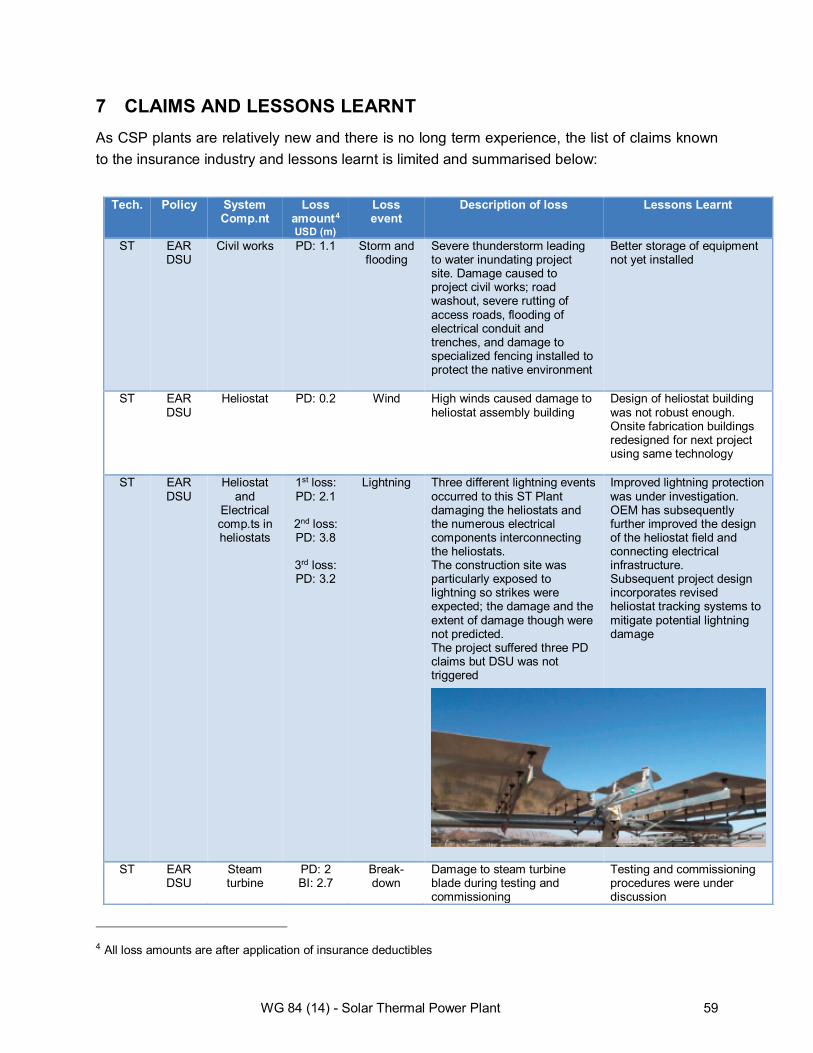
7 CLAIMS AND LESSONS LEARNT As CSP plants are relatively new and there is no long term experience, the list of claims known to the insurance industry and lessons learnt is limited and summarised below:
Tech. Policy System Comp.nt
Loss amount4 USD (m)
Loss event
Description of loss Lessons Learnt
ST EAR DSU
Civil works PD: 1.1 Storm and flooding
Severe thunderstorm leading to water inundating project site. Damage caused to project civil works; road washout, severe rutting of access roads, flooding of electrical conduit and trenches, and damage to specialized fencing installed to protect the native environment
Better storage of equipment not yet installed
ST
EAR DSU
Heliostat PD: 0.2 Wind High winds caused damage to heliostat assembly building
Design of heliostat building was not robust enough. Onsite fabrication buildings redesigned for next project using same technology
ST
EAR DSU
Heliostat and
Electrical comp.ts in heliostats
1st loss: PD: 2.1
2nd loss: PD: 3.8
3rd loss: PD: 3.2
Lightning Three different lightning events occurred to this ST Plant damaging the heliostats and the numerous electrical components interconnecting the heliostats. The construction site was particularly exposed to lightning so strikes were expected; the damage and the extent of damage though were not predicted. The project suffered three PD claims but DSU was not triggered
Improved lightning protection was under investigation. OEM has subsequently further improved the design of the heliostat field and connecting electrical infrastructure. Subsequent project design incorporates revised heliostat tracking systems to mitigate potential lightning damage
ST EAR DSU
Steam turbine
PD: 2 BI: 2.7
Break-down
Damage to steam turbine blade during testing and commissioning
Testing and commissioning procedures were under discussion
4 All loss amounts are after application of insurance deductibles
WG 84 (14) - Solar Thermal Power Plant 59

Tech. Policy System Comp.nt
Loss amount4 USD (m)
Loss event
Description of loss Lessons Learnt
ST EAR Absorber tubes
Not known
Poor workman
ship
During the installation of the reflector shields 2,300 of the 22,500 installed absorber tubes suffered scratches on the glass surface of the absorber. The scratching led to local stress concentration and reduced the strength of the glass which resulted in damage to the glass itself during the commissioning stage due to thermal expansion and vibration of the system
This damage occurred over a period of months due to the inattentiveness of the operatives during drilling. These activities were carried out after installation of the solar field, including the absorber tubes. A better workmanship procedure, followed by a more thorough QA/QC procedure is required
PT
EAR DSU
Boaster Heater
PD: 13 DSU: 8
Fire Fire in a booster heater during construction
To expedite completion of the project, several safety features were disabled during commissioning causing ignition of the boaster heater when it was fired up without steam
PT OAR BI
Collectors Approx. PD: 1 BI: 0.5
Break-down
followed by fire
Fire damage following breakage of joints that allow movement of the collectors. Manufacturer responded to physical damage loss (PD) while insurers picked up the BI cover, which was not substantial as plant was still able to operate most collectors
Redesign of the collector joint including, we believe, a retrofit of undamaged joints
PT OAR BI
HTF PD: 0.7 Break-down
Oil leakage due to break in an oil sample valve in the pipe that collects oil from the solar field
WG 84 (14) - Solar Thermal Power Plant 60

Tech. Policy System Comp.nt
Loss amount4 USD (m)
Loss event
Description of loss Lessons Learnt
PT OAR BI
HTF 1st loss: PD: 1.6 BI: 4.8
2nd loss: PD: 3.4 BI: 14.3
Break-down
Several losses of HTF following failure of heat exchangers at the same plant.
The design of the heat exchangers was the issue. The OEM provided and installed a redesigned heat exchanger system on this plant and on all new plants thereafter, including retrofitting some plants already built
PT EAR DSU
HTF Expansion
Tank
PD: 2 DSU: 4.1
Defect Failure of HTF expansion tank due to welding defect causing HTF leakage during commissioning. Two other HTF Tanks (Overflow HTF Tanks) from the same manufacturer were found to have the same defect.
A cheaper method for production of the tanks was utilised and the tanks had to be retrofitted with additional plating in order to avoid further failures.
PT
OAR BI
BOP Approx. PD: 3.1 BI: 4.1
Flood Flood causing damage to power block and areas of the solar field
PT OAR BI
Turbine PD: 2.9 BI: 0.25
Defect Defect in turbine installation leading to turbine damage
This was a manufacturing failure. It is unknown if the OEM has changed procedures to prevent future similar manufacturing failures.
PT OAR BI
Collectors PD: 4 Storm Storm with initial damage including solar field assembly building, solar collector assemblies and mirrors, erosion of roads, finished solar field terraces, foundation structures, fencing, undermined foundations and exposed underground piping, wiring and cabling. Crates and on site storage equipment became submerged. Contractor construction equipment and tools were also underwater.
This site is exposed to extreme weather and this was considered a fortuitous loss.
LF
OAR A-Frame of Fresnel receiver
PD: 2.9 Collapse Failure of the welding of A-frames, which hold the linear fresnel receivers in place, leading to a ‘domino’ effect with all A-frames in a row collapsing in sequence damaging the A-frames, the receivers and the ancillary equipment in that location.
Improved vetting process for OEM suppliers and more robust QC processes for fabrication.
WG 84 (14) - Solar Thermal Power Plant 61

Tech. Policy System Comp.nt
Loss amount4 USD (m)
Loss event
Description of loss Lessons Learnt
PT
OAR BI
BOP/HTF PD: 1.4
Break-down
Damage to tubes forming part of the power block. The damage was contained in the section of plant comprising the heat exchangers, the salt transfer pipes and the HTF tubes. Damage limited to the HTF tubes and to a lesser extent the salt transfer pipes. Cause of loss is under investigation but expected to be a leak in the heat exchangers.
PT OAR BI
Drive PD: 0.48 Program Error
Damage to drive pylons caused by software error
Redesign of certain aspects of the control software.
Table 3 – Loss Table
WG 84 (14) - Solar Thermal Power Plant 62

8 CONCLUSION The solar thermal power industry has been growing rapidly over the past few years. A recent study by the International Energy European Solar Thermal Electricity Association suggested that CSP plants could provide up to 25 percent of the world's electricity needs by 2050. However, despite its potential, CSP technology lacks a long deployment track-record and still comes with high technology cost and risks. Therefore, more deployment experience is needed to increase understanding and make the technology more competitive.
Adequate risk management measures have become fundamental to the success of this industry and to the acceleration of CSP market penetration. Risks need to be properly assessed from the design stage, through the installation, up to the operational stage of each CSP project. These risks need to be shifted to appropriate project participants with the ability and expertise to better manage those risks; technology challenges, nat cat exposure, and all other issues, if successfully addressed by the appropriate parties, would attract new potential investors and developers, and would reduce the barriers to bankability.
In this risk management process Insurance has an important role as it offers insurance products adequate to cover the evolving risks in a CSP plant during its construction and operation, including innovative insurance products aimed at protecting a company's earnings volatility.
But as the solar thermal power sector matures, to secure a bright and sunny future for this industry there is a need to engage the various players in securing skill and know-how transfer, to apply a thorough risk management approach on each project, and to share lessons learnt.
The authors hope that this paper, for its small part, has contributed to the achievement of this intent.
WG 84 (14) - Solar Thermal Power Plant 63

9 APPENDIX 9.1 Appendix – Direct Normal Irradiance (DNI
9.2 Appendix - CSP hybrid projects
9.3 Appendix - CSP technology developments in 2020-2030
9.4 Appendix – Spanish Policy
WG 84 (14) - Solar Thermal Power Plant 64

9.1 Appendix – Direct Normal Irradiance (DNI) DNI represents the direct beam irradiance received on a surface perpendicular to the sun's rays.
CSP technologies, unlike PV technologies, require large DNI in order to generate electricity as only strong direct sunlight can be concentrated to the temperatures required to generate electricity. Hence CSP power plants are very much dependent on high DNI in regions like North Africa, Middle East, Southern Africa, Australia, the Western United States and parts of South America (Fig. 13).
Fig. 13 – Yearly sum of DNI
As presented by IRENA, the International Renewable Energy Agency, the lower Levelised Cost of Electricity (LCOE) of CSP plants is strongly correlated with the DNI. Locations with high DNI will produce more energy, hence greater generation of electricity and a correspondingly lower LCOE. In fact assuming a typical value of DNI of 2100 kWh/m2/year for Spain, the estimated LCOE of a CSP plant is expected to decline by 4.5% for every 100 kWh/m2/year that the DNI exceeds 2100 for a given CSP plant with identical design and capital costs. For instance, the LCOE of an identical CSP plant will be around one-quarter lower in good sites in the United States, Algeria or South Africa where the DNI is around 2700 kWh/m2/year than for a site in Spain with a DNI of 2100 kWh/m2/year (A.T. Kearney and ESTELA, 2010) as shown in Fig. 14.
WG 84 (14) - Solar Thermal Power Plant 65

Fig. 14 – The LCOE of CSP plants as a function of DNI (Source: A.T. Kearney and ESTELA, 2010.)
WG 84 (14) - Solar Thermal Power Plant 66

9.2 Appendix - CSP hybrid projects CSP providers have already begun devising hybrid power plants combining CSP with fossil fuel generation. The benefit of such installations is that the CSP aspect partially subsidises the fossil fuels intake of the plant by heating the feed water prior to entry into the boiler and increases the cycle’s yield whilst reducing carbon dioxide emissions.
There are various concepts available for the integration of solar collectors into conventional power cycles aimed either at thermodynamic cycle integration or combining the solar power generation with fossil generation as described below.
• Solar Live Steam in hybrid Rankine plants (Coupling a solar field with a conventional coal-fired power plant), Solar Gas turbine combined cycle - Due to the high concentration factors, solar towers (central receivers) and dishes can produce very high temperatures (above 1,000°C) for use directly in gas turbines or to complement the gas turbine combustion chamber.
• Combined Heat and Power solar plant - Similar to conventional combined heat and power, in this option a solar thermal electricity plant is combined with a lower temperature thermal application such as sea water desalination or air conditioning.
• Integrated solar combined cycle (ISCC) - The Integrated Solar Combined Cycle System (ISCC)
was initially proposed as a way of integrating a parabolic trough solar plant with modern combined-cycle power plants. The basis of this plant type is a combined cycle plant consisting of a high-temperature gas turbine and a bottoming steam turbine. The steam for the steam turbine in an ISCCS plant is provided by two heat sources: the heat recovery steam generator using the exhaust gas of the gas turbine and the solar field. The size of the steam turbine in an ISCCS is larger than it would be in a conventional combined cycle. The main drawback of the technology is the part load losses during operating hours when there is no solar energy input. ISCC plants can achieve efficiencies in the order of 67%, which is 10% higher than a conventional combined cycle plant
• Solar Feed Water Preheating: In this option, solar thermal heat is used for preheating feed-
water in large-scale conventional Rankine plants, substituting steam that would otherwise be bled from the turbine
• Solar Process Heat Applications - The slow pace of CSP market introduction is mainly related
to the very large investments related to this type of renewable energy technology.
WG 84 (14) - Solar Thermal Power Plant 67

9.3 Appendix - CSP technology developments in 2020-2030 Parabolic Trough 2020-2030: 2020 and 2030 technologies show 5% and 10% improvements in performance over 2010 trough technology. This is due to the introduction of Direct Steam Generation (DSG) trough collector technology.
DSG improves efficiency in the solar field and reduces equipment costs by eliminating the HTF system. Power cycle efficiency is assumed to improve due to higher solar steam temperatures. Solar parasitics are reduced through elimination of HTF pumps. Although feedwater must still be pumped through the solar field, it is pumped at a much lower mass flow rate. This design also assumes that a low cost thermal storage system with an 85% round-trip efficiency is developed for use with the DSG solar field. Conversion to the DSG collector system could allow the net solar-to-electric efficiency to increase to over 16% by 2030.
The changes between 2020 and 2030 are assumed to be evolutionary improvements and fine tuning of the DSG technology.
Solar Power Tower 2020-2030: 2020 Technology: Power plant size is assumed to remain at 200 MW. Power towers built between the years 2010 and 2020 should have a receiver that has a significantly higher efficiency than is currently possible with today’s technology. Receivers within current power towers are coated with a highly absorptive black paint. However, the emissivity5 of the paint is also high which leads to a relatively large radiation loss. Future power tower receivers will be coated with a selective surface with a very low emissivity that will significantly reduce radiation losses. Selective surfaces similar to what is needed are currently used in solar parabolic trough receivers. Additional research is needed to produce a surface that will not degrade at the higher operating temperature of the tower (i.e., 650ºC/1,202ºF vs. 400°C/752ºF). Given this improvement, scoping calculations indicate that annual receiver efficiency should be improved to about 90%.
By 2020, further improvements in heliostat manufacturing techniques, along with significant increases in annual production, are expected to lower heliostat costs to their final mature value (~$70/m2). This is expected to result in the reflective capability of the mirrors improving from the current value of 94% to a value of at least 97%. Advanced reflective materials are currently being investigated in the laboratory. As the technology reaches maturity, plant parasitics will be fully optimized and plant availability will also improve. Combining all the effects described above, annual plant efficiency is expected to rise to 20% and the annual capacity factor should rise above 75%.
2030 Technology: Ideas under consideration are an advanced receiver that is capable of efficiently heating air to gas-turbine temperatures (>1,400ºC/2,552ºF) and pressures (>1,500 kPa)
5 The emissivity of a material is the relative ability of its surface to emit energy by radiation.
WG 84 (14) - Solar Thermal Power Plant 68

in conjunction with a high-temperature phase-change thermal storage system. If this can be achieved, large solar-only plants with a combined-cycle power block efficiency of 60% or more might be achieved. In addition, as receiver temperatures exceed 1,000ºC (1,832ºF), thermal-chemical approaches to hydrogen generation could be exploited using solar power towers.
Solar Dish Engine 2020-2030: Production levels expected for 2020 and 2030 are 50,000 and 60,000 modules per year, respectively. Evolutionary improvements in mirror, receiver, and/or engine designs have been assumed. Advanced concepts (e.g., volumetric Stirling receivers) and/or materials, which could improve annual efficiency by an additional 10%, have not been included in the cost projections. With these improvements, installed costs of less than USD1,000/kW are not unrealistic.
WG 84 (14) - Solar Thermal Power Plant 69

9.4 Appendix – Spanish Policy Revenues in the renewables industry in Spain are strongly linked to regulators’ views on the industry, since the installation costs are still not as competitive as in conventional power plants. Over the last few years part of the income has been subsidized through governmental funding, to reduce national dependence on fossil fuels and imports. But due to the current economic situation, renewable energy legislation in Spain has undergone significant changes, going from fostering investment in these kinds of generation plants to almost bringing it to a standstill.
In 2007 a new law was passed in order to regulate the production of electricity carried out under a “special regime”, affecting mainly renewable energy. This meant a major boost for, among others, solar energy (CSP or photovoltaic). The main reason was the high financial rewards that it offered (420 EUR/MWh for photovoltaic and 290EUR/MWh for CSP), which guaranteed a return on investment rate above 20%. In addition to this, easy access to financial aid led to the installation of thousands of MW of both CSP and PV.
After some years of large investments in this energy source and owing to the deep economic crisis suffered in Spain, a number of legislative changes relating to sustainable energy have taken place since 2012 and these are affecting investors´ interests. Not only has a new 7% tax been applied to energy generation, but electricity plants’ income levels have also decreased considerably due to reductions in state subsidies. These changes have led to a severe decline in investment, which has now almost ground to a halt.
The above-mentioned income reductions have significantly affected the operation and management of CSP generation plants and, in general, those plants which have published their results for 2013 have reported losses. In this scenario, cost reduction seems to be the only solution for making the operation of these plants profitable.
Among the different measures taken to reduce costs, those related to maintenance policies are of special concern for the insurance sector. These new policies may result in a higher risk level as well as an increase in the number of insurance claims.
In this new scenario it is strongly recommended that close attention should be paid to the quality of plant maintenance in future years.
WG 84 (14) - Solar Thermal Power Plant 70

10 REFERENCES "Solar Energy Perspectives, Renewable Energy Technolgies" of International Energy Agency (IEA) "Catching the sun" by Mark Crawford, ASME.org "Technology Assessment of CSP Technologies for a Site Specific Project in South Africa Final Report", Fichtner (2010), The World Bank and ESMAP, Washington D.C. "Technology Roadmap, Concentrating Solar Power", International Energy Agency (IEA)
"Renewable Energy Technologies: cost analysis series" Volume 1: Power Sector Issuew 2/5 Concentrating Solar Power, Irena Working Paper, International Renewable Energy Agency "Salt Heat Transfer Fluids in CSP", Debbie Sniderman, ASME "Hazard analysis of glint and glare from concentrating solar power plants", Clifford K. Ho, Cheryl M. Ghanbari, and Richard B. Diver, from SolarPACES 2009, Berlin, Germany, September 15-18, 2009 "Heat Transfer Fluid Leaks: Break the Fire Triangle", Conrad E. Gamble and Matthias Schopf, Solutia Inc. "Further Analysis of accelerated exposure testing of thin-glass mirror matrix" by C.E. Kennedy K., Terwilliger, G. J. Jorgensen, National Renewable Energy Laboratory (NREL) "Molten salt: how to avoid the big freeze" by Jason Deign, CSP today
"Solar-Augment Potential of U.S. Fossil-Fired Power Plants", by Craig Turchi and Nicholas Langle of National Renewable Energy Laboratory and Robin Bedilion and Cara Libby of the Electric Power Research Institute "Integrating Renewable Energy Resources Within the Oil Industry, Concentrated Solar Power (CSP) & Enhanced Oil Recovery (EOR)" from GDP Capital
"Profiling the risks in solar and wind, A case for new risk management approaches in the renewable energy sector" by Guy Turner, Sam Roots, Michael Wiltshire (Bloom-berg New Energy
WG 84 (14) - Solar Thermal Power Plant 71

Finance); Juerg Trueb, Stuart Brown, Guido Benz, Martin Hegelbach (Swiss Re Corporate Solutions)
"Distant Observer Tool Quickly Identifies Costly Flaws in CSP Fields" by NREL
"Grid integration of large-capacity Renewable Energy sources and use of large-capacity Electrical Energy Storage" by International Electrotechnical Commission "DSU Sun Insured Worksheet" IMIA Conference 2013 –New Delhi
WG 84 (14) - Solar Thermal Power Plant 72

11 EXTERNAL LINKS CSP Today (http://social.csptoday.com/) Desertec Foundation (http://www.desertec.org/en/global-mission/) ESTELA European Solar Thermal Electricity Association (http://www.estelasolar.eu/) Focus (http://www.renewableenergyfocus.com/) IEA International Energy Agency (http://www.iea.org/topics/solarpvandcsp/) IMIA International Association of Engineering Insurers (http://www.imia.com/) ISES International Solar Energy Society http://www.ises.org/index.html) Renewable Energy World (http://www.renewableenergyworld.com/rea/home) Solar Paces (http://www.solarpaces.org/) Wikipedia (www.wikipedia.org)
WG 84 (14) - Solar Thermal Power Plant 73