Embed Size (px)
Citation preview
8/2/2019 Solar Plant 1
http://slidepdf.com/reader/full/solar-plant-1 1/17
Identification Of Major
Components1. Parabolic Trough Solar Collector
2. Concentrator Structure
3. Vacuum Tubes4. Pumps
5. Condenser
6. Steam Engine
7. Generator

8/2/2019 Solar Plant 1
http://slidepdf.com/reader/full/solar-plant-1 2/17
PARABOLIC TROUGH SOLARCOLLECTOR
Concentrates parallel incident solar raysonto the vacuum tubeReceivers are aligned along the parabolicline focusA tracking system will be employed so thatthe parabolic receivers always point in the
direction of the sun
8/2/2019 Solar Plant 1
http://slidepdf.com/reader/full/solar-plant-1 3/17
PARABOLIC TROUGH SOLARCOLLECTOR
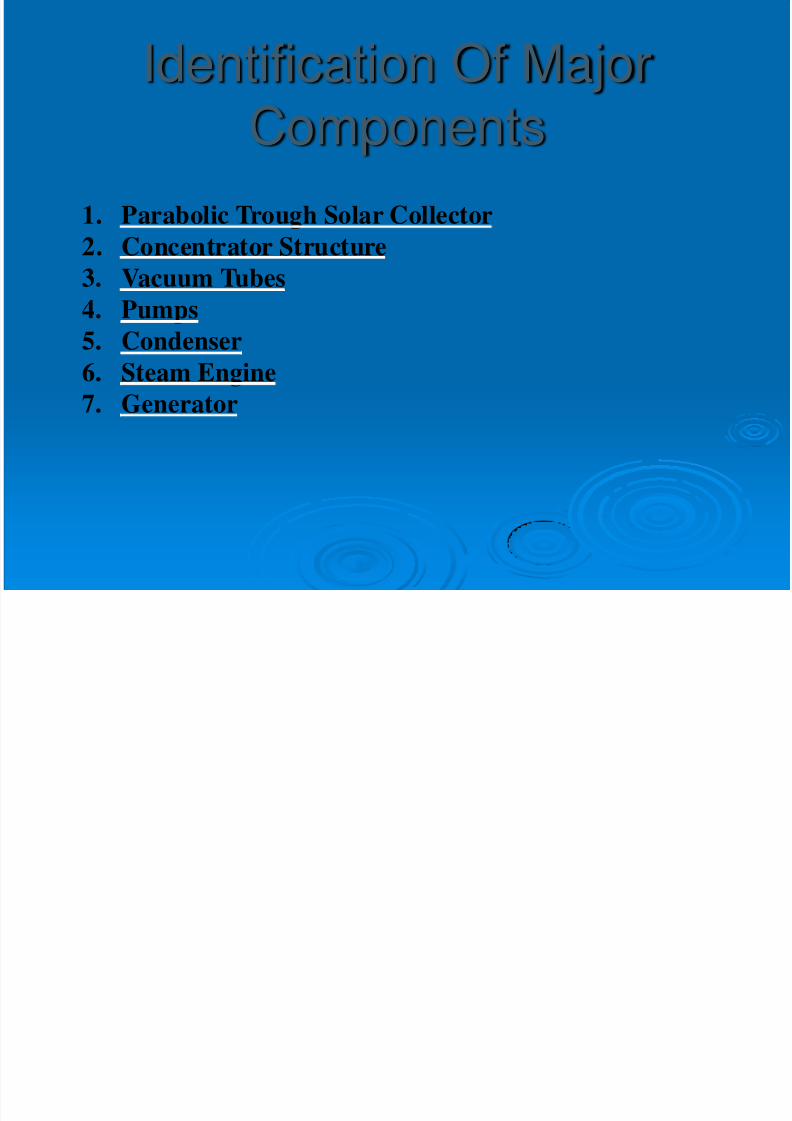
The cost of the parabolic mirrors is 750rupees per square foot.An alternative solution is required to avoidthe expensive parabolic mirrors.

8/2/2019 Solar Plant 1
http://slidepdf.com/reader/full/solar-plant-1 4/17
PARABOLIC TROUGH SOLARCOLLECTOR
Alternate Proposed Design
8/2/2019 Solar Plant 1
http://slidepdf.com/reader/full/solar-plant-1 5/17
PARABOLIC TROUGH SOLARCOLLECTOR
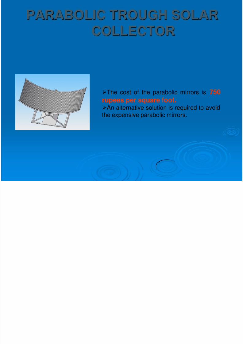
Thin and flat strips of mirror will beused in place of the continuous parabolicmirror.The strips of mirror will be supported
on aluminum T- sectionsArranged at the proper angles so thatthe incident parallel solar rays will bereflected onto a single line focus.Same result as that of the parabolicmirrors at a fraction of the original cost.
A Comparatively longer lifespan.
8/2/2019 Solar Plant 1
http://slidepdf.com/reader/full/solar-plant-1 6/17
Mirrors are fragile and needed to be handled carefully to avoidbreakageMirror frames must be strong enough to withstand wind loadingand the forces involved in supporting and tracking the mirror.The pipes used should be supported properly to avoid saggingat high temperatures.
Risk Analysis
PARABOLIC TROUGH SOLARCOLLECTOR

8/2/2019 Solar Plant 1
http://slidepdf.com/reader/full/solar-plant-1 7/17
CONCENTRATOR STRUCTURE
Supports the mirrors and receivers,maintaining them in optical alignmentWithstands external forces, such as windAllows the collector to rotate, so the mirrorsand receiver can track the sun.
8/2/2019 Solar Plant 1
http://slidepdf.com/reader/full/solar-plant-1 8/17
Mirror strips are fragile and hence need to be mounted on thesupporting T-Sections as soon as they are cutAngle alignment needs to be done accurately and carefullySupporting Frame members should be strong enough tosupport the structure without failureGaps between mirrors must be adequate to prevent lightblockage and reduce wind loading while keeping the area assmall as possible
CONCENTRATOR STRUCTURE
Risk Analysis
8/2/2019 Solar Plant 1
http://slidepdf.com/reader/full/solar-plant-1 9/17
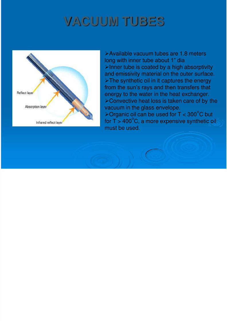
VACUUM TUBES
Available vacuum tubes are 1.8 meterslong with inner tube about 1” dia Inner tube is coated by a high absorptivityand emissivity material on the outer surface.
The synthetic oil in it captures the energyfrom the sun’s rays and then transfers that
energy to the water in the heat exchanger.Convective heat loss is taken care of by thevacuum in the glass envelope.Organic oil can be used for T < 300
oC but
for T > 400oC, a more expensive synthetic oilmust be used.
8/2/2019 Solar Plant 1
http://slidepdf.com/reader/full/solar-plant-1 10/17
Vacuum tubes are fragile and need to be handled carefullyIn a metal and glass vacuum tube the metal tube should be ableto withstand thermal stress so that it does not sag and damagethe glassSealing is an important factor and needs to be done perfectly to
achieve good vacuum
VACUUM TUBES
Risk Analysis
8/2/2019 Solar Plant 1
http://slidepdf.com/reader/full/solar-plant-1 11/17
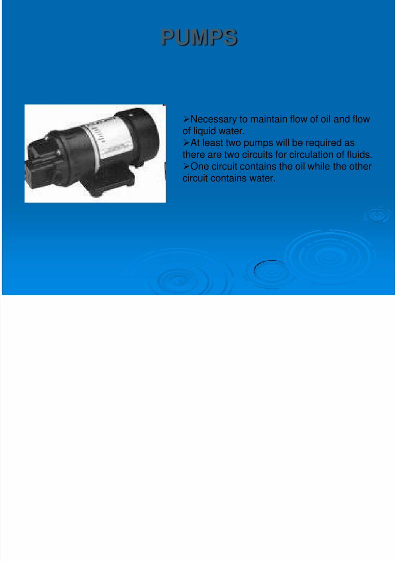
PUMPS
Necessary to maintain flow of oil and flowof liquid water.At least two pumps will be required asthere are two circuits for circulation of fluids.One circuit contains the oil while the othercircuit contains water.
8/2/2019 Solar Plant 1
http://slidepdf.com/reader/full/solar-plant-1 12/17
Pumps may not be found according to our requirementsPumps may get damaged during operation so spares arenecessary
PUMPS
Risk Analysis
8/2/2019 Solar Plant 1
http://slidepdf.com/reader/full/solar-plant-1 13/17
CONDENSER
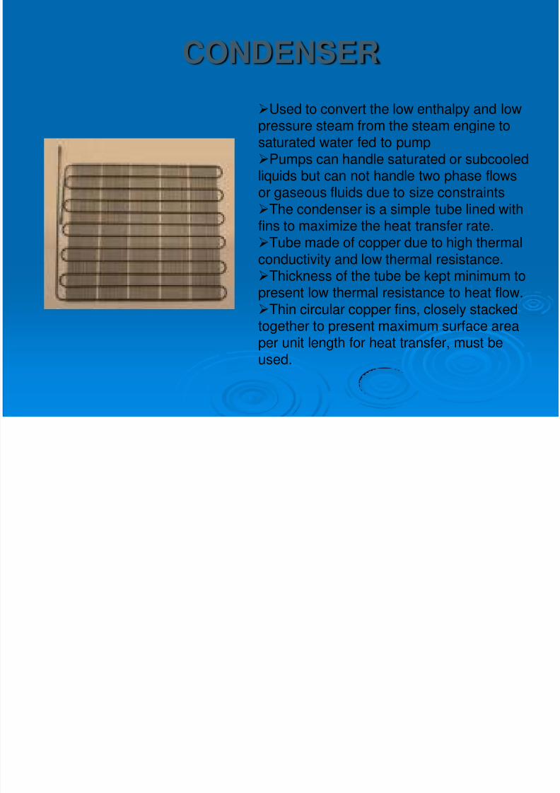
Used to convert the low enthalpy and lowpressure steam from the steam engine tosaturated water fed to pumpPumps can handle saturated or subcooledliquids but can not handle two phase flows
or gaseous fluids due to size constraintsThe condenser is a simple tube lined withfins to maximize the heat transfer rate.Tube made of copper due to high thermalconductivity and low thermal resistance.Thickness of the tube be kept minimum to
present low thermal resistance to heat flow.Thin circular copper fins, closely stackedtogether to present maximum surface areaper unit length for heat transfer, must beused.

8/2/2019 Solar Plant 1
http://slidepdf.com/reader/full/solar-plant-1 14/17
CONDENSER
Condenser should be completely isolated from the atmosphereto ensure close cycle operationIt should be completely clean and scale free inside and outsideto maximize heat transfer and minimize pressure loss
Risk Analysis
8/2/2019 Solar Plant 1
http://slidepdf.com/reader/full/solar-plant-1 15/17
STEAM ENGINE
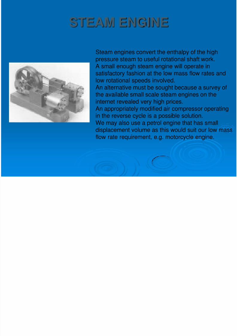
Steam engines convert the enthalpy of the highpressure steam to useful rotational shaft work.A small enough steam engine will operate insatisfactory fashion at the low mass flow rates and
low rotational speeds involved.An alternative must be sought because a survey ofthe available small scale steam engines on theinternet revealed very high prices.An appropriately modified air compressor operatingin the reverse cycle is a possible solution.
We may also use a petrol engine that has smalldisplacement volume as this would suit our low massflow rate requirement, e.g. motorcycle engine.
8/2/2019 Solar Plant 1
http://slidepdf.com/reader/full/solar-plant-1 16/17
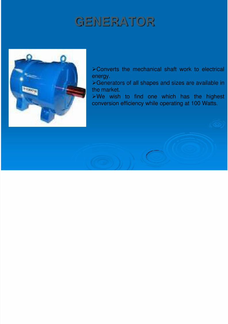
GENERATOR
Converts the mechanical shaft work to electricalenergy.Generators of all shapes and sizes are available inthe market.We wish to find one which has the highestconversion efficiency while operating at 100 Watts.

8/2/2019 Solar Plant 1
http://slidepdf.com/reader/full/solar-plant-1 17/17
Generator of desired specifications is unavailable in the markettherefore different available generators will be tested and onewhich gives highest conversion efficiency will be purchased andinstalled.
GENERATOR
Risk Analysis