Embed Size (px)
Citation preview

ORIGINAL PAPER
Michael Rodgers Æ Xinmin Zhan Æ Edmond O’Reilly
Small-scale domestic wastewater treatment using an alternatingpumped sequencing batch biofilm reactor system
Received: 23 November 2005 / Accepted: 28 November 2005 / Published online: 12 January 2006� Springer-Verlag 2006
Abstract An alternating pumped sequencing batch bio-film reactor (APSBBR) system was developed to treatsmall-scale domestic wastewater. This laboratory systemhad two reactor tanks, Reactor 1 and Reactor 2, with twoidentical plastic biofilm modules in each reactor. Reactor1 of the APSBBR had five operational phases—fill, an-oxic, aerobic, settle and draw. In the aerobic phase, thewastewater was circulated between the two reactor tankswith centrifugal pumps and aeration was mainlyachieved through oxygen absorption by microorganismsin the biofilms when they were exposed to the air. Thispaper details the performance of the APSBBR system intreating synthetic domestic wastewater over 18 months.The effluent from the APSBBR system satisfied theEuropean Wastewater Treatment Directive require-ments, with respect to COD, ammonium-nitrogen andsuspended solids. The biofilm growth in the two reactortanks was different due to the difference in substrateloadings and growth conditions.
Keywords Alternating pumped sequencing batchbiofilm reactor Æ Small-scale domestic wastewater ÆCOD removal Æ Nitrogen removal Æ Biofilm growth
Introduction
In 2004, the Irish EPA published a report on wastewaterand established that there were 443 agglomerations (Anagglomeration is defined as an area where the popula-tion and/or economic activities are sufficiently concen-trated for urban wastewater to be collected andtransported to an urban wastewater treatment plant orto a final discharge point.) with a population-equivalent
(PE) greater than 500 during 2002–2003 [1]. Of the 443agglomerations, 18% of wastewater received no treat-ment, 13% received preliminary treatment, 2% receivedprimary treatment, 58% received secondary treatmentand 9% received tertiary treatment. Almost all ofIreland’s wastewaters, irrespective of the level of treat-ment, are discharged to estuaries and freshwaters.
All member states of the European Union are boundby the Urban Wastewater Treatment Directive (CouncilDirective 91/271/EEC). The Directive requires allmember states to identify sensitive receiving waters andprovide a level of secondary treatment for dischargesaccording to the sensitivity of the receiving water body.Emission limit values of 5-day biochemical oxygen de-mand, chemical oxygen demand (COD) and suspendedsolids (SS) for discharges to non-sensitive water are 25,125 and 35 mg/l, respectively. The Directive stipulatesthat by 31 December 2005, discharges from agglomera-tions with a PE of less than 2,000 must undergoappropriate treatment prior to entering freshwaters andestuaries.
However, the design and operation of small waste-water treatment plants are ‘‘a challenge to wastewaterengineers’’ [2]. Conventional suspended-growth acti-vated sludge processes, which have been used success-fully and widely to treat municipal wastewater duringthe last hundred years, are not always suitable fortreating small wastewater flows. Factors that should betaken into account when designing small wastewatertreatment plants include land requirement, constructioncost, operating cost, maintenance and landscape. Theland requirement must be small so the treatment facili-ties can be put within the premises of single houses andhotels. The per capita operating cost and the simplicityof the operation are very critical to the process. Theplant should be operated without the continuoussupervision of highly qualified operators and shouldonly need to be checked a few times a year. The main-tenance on the mechanical parts should be easy. Giventhat biological treatment systems are used, sludge dis-posal should be infrequent—once or twice per annum.
M. Rodgers Æ X. Zhan (&) Æ E. O’ReillyDepartment of Civil Engineering, National University of Ireland,Galway, IrelandE-mail: [email protected].: +353-91-495239Fax: +353-91-494507
Bioprocess Biosyst Eng (2006) 28: 323–330DOI 10.1007/s00449-005-0038-8
Finally, the designer should make sure that the plant orfacilities is in keeping with the surroundings. Hence, thefacilities for small-scale wastewater treatment should benot only environmentally sound but also humanfriendly.
The objectives of this study were to develop andexamine a new system that would satisfy the require-ments associated with small-scale wastewater treatmentpresented above.
This system—an alternating pumped sequencingbatch biofilm reactor (APSBBR)—was constructed andlocated in a room where the temperature was controlledat 11�C. The laboratory-scale unit comprised two reac-tor tanks where biofilm modules with vertical columnswere installed. The performance of the novel system intreating synthetic domestic wastewater was monitoredover a period of 18 months in the laboratory.
The APSBBR system had five operational phases:fill, anoxic, aeration, settle and draw. During the aera-tion phase water was pumped intermittently from onereactor tank to the other resulting in aeration. Duringthe anoxic phase, no pumping occurred, causing anoxicconditions in one reactor, which led to nitrogen re-moval. At the end of SBBR cycles, the treated effluentwas drawn off through an open solenoid valve. Com-pared with other biofilm systems, this system is suitablefor small-scale wastewater treatment due to two mainreasons. First, the transfer of oxygen into the waste-water in the aerobic phase is mainly achieved by alter-natively moving water between the two reactor tanks,leading to the exposure of biofilms to the air. Thiseliminates the need for air compressors, diffusers andother ancillary equipment. Second, there are no movingparts in the system. The only mechanical equipmentwhich require maintenance are the pumps. Conse-quently, low capital cost and little maintenance isassociated with the system.
Materials and methods
Laboratory scale APSBBR system
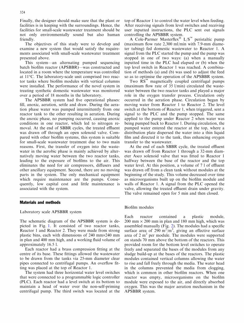
The schematic diagram of the APSBBR system is de-picted in Fig. 1. It consisted of two reactor tanks,Reactor 1 and Reactor 2. They were made from strongplastic bins, each with dimensions of 240 mm·240 mmin plan and 400 mm high, and a working fluid volume ofapproximately 16.5 l.
Each reactor had a brass compression fitting at thecentre of its base. These fittings allowed the wastewaterto be drawn from the tanks via 25-mm diameter clearpipes connected to centrifugal pumps. An overflow fit-ting was placed at the top of Reactor 1.
The system had three horizontal water level switchesthat were connected to a programmable logic controller(PLC). Each reactor had a level switch at its bottom tomaintain a head of water over the non-self-primingcentrifugal pump. The third switch was located at the
top of Reactor 1 to control the water level when feeding.After receiving signals from level switches and receivinguser inputted instructions, the PLC sent out signalscontrolling the APSBBR system.
A Cole-Parmer Masterflex� L/S� peristaltic pump(maximum flow rate 2,300 ml/min with 7.9-mm diame-ter tubing) fed domestic wastewater to Reactor 1. Asignal from the PLC started the pump and the pump wasstopped in one of two ways: (a) when a manuallyinputted time in the PLC had elapsed or (b) when thetop level switch in Reactor 1 was reached. A combina-tion of methods (a) and (b) was used to adjust the feedso as to optimise the operation of the APSBBR system.
Two RS� magnetically coupled centrifugal pumps(maximum flow rate of 35 l/min) circulated the waste-water between the two reactor tanks and played a majorrole in the oxygen transfer process. Circulation onlyoccurred in the aeration phase. Circulation began bymoving water from Reactor 1 to Reactor 2. The levelswitch at the bottom of Reactor 1, when triggered, sent asignal to the PLC and the pump stopped. The sameapplied to the pump under Reactor 2 when water wasbeing pumped back to Reactor 1. During circulation, thepumped water entered the reactor at the top, where adistribution plate dispersed the water into a thin liquidfilm and directed it to the tank, thus enhancing oxygentransfer to the wastewater.
At the end of each SBBR cycle, the treated effluentwas drawn off from Reactor 1 through a 32-mm diam-eter Asco solenoid valve that was fitted to Reactor 1halfway between the base of the reactor and the topwater level. At this position, a volume of 7 l of effluentwas drawn off from a clean tank without modules at thebeginning of the study. This volume decreased over timeas microorganisms built up on the biofilm module andwalls of Reactor 1. A signal from the PLC opened thevalve, allowing the treated effluent drain under gravity.The valve remained open for 5 min and then closed.
Biofilm modules
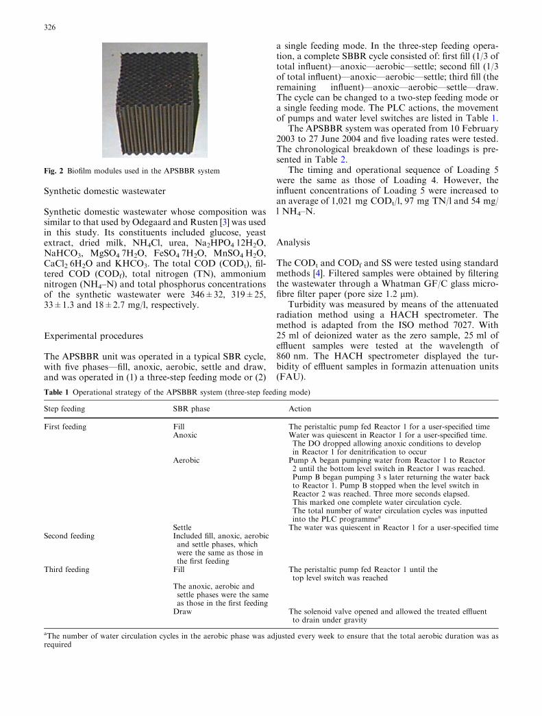
Each reactor contained a plastic module,200 mm · 200 mm in plan and 180 mm high, which wasassembled manually (Fig. 2). The modules had a specificsurface area of 290 m2/m3, giving an effective surfacearea of 2 m2 per module. The modules were supportedon stands 70 mm above the bottom of the reactors. Thisprovided room for the bottom level switches to operatefreely and separated the bases of the modules from anysludge build-up at the bases of the reactors. The plasticmodules contained vertical columns allowing the waterto rise and fall freely through the media. The water headin the columns prevented the media from clogging,which is common in other biofilm reactors. When onereactor was empty, microorganisms on the biofilmmodule were exposed to the air, and directly absorbedoxygen. This was the major aeration mechanism in theAPSBBR system.
324

Flow FROM Reactor 1 TO Reactor 2
Flow FROM Reactor 2 TO Reactor 1
Flow FROM Reactor 1
Flow TO Reactor 2
Flow FROM Reactor 2 TO Reactor 1
Dispersion plate
Biofilm module
Float level switch
Decant W L
Pump
Module stand
Top WL
Bottom WL
Reactor 1
Reactor 2
Reactor 1
Biofilm module
Solenoid valve position
Frame
Frame
Section A-A
Plan View
Section B-B
Pump Pump
Reactor 2 Reactor 1
Solenoid Valve
A A
B
B
Fig. 1 Plan and section views of the APSBBR system, where flow directions and unit components are indicated
325
Synthetic domestic wastewater
Synthetic domestic wastewater whose composition wassimilar to that used by Odegaard and Rusten [3] was usedin this study. Its constituents included glucose, yeastextract, dried milk, NH4Cl, urea, Na2HPO4Æ12H2O,NaHCO3, MgSO4Æ7H2O, FeSO4Æ7H2O, MnSO4ÆH2O,CaCl2Æ6H2O and KHCO3. The total COD (CODt), fil-tered COD (CODf), total nitrogen (TN), ammoniumnitrogen (NH4–N) and total phosphorus concentrationsof the synthetic wastewater were 346±32, 319±25,33±1.3 and 18±2.7 mg/l, respectively.
Experimental procedures
The APSBBR unit was operated in a typical SBR cycle,with five phases—fill, anoxic, aerobic, settle and draw,and was operated in (1) a three-step feeding mode or (2)
a single feeding mode. In the three-step feeding opera-tion, a complete SBBR cycle consisted of: first fill (1/3 oftotal influent)—anoxic—aerobic—settle; second fill (1/3of total influent)—anoxic—aerobic—settle; third fill (theremaining influent)—anoxic—aerobic—settle—draw.The cycle can be changed to a two-step feeding mode ora single feeding mode. The PLC actions, the movementof pumps and water level switches are listed in Table 1.
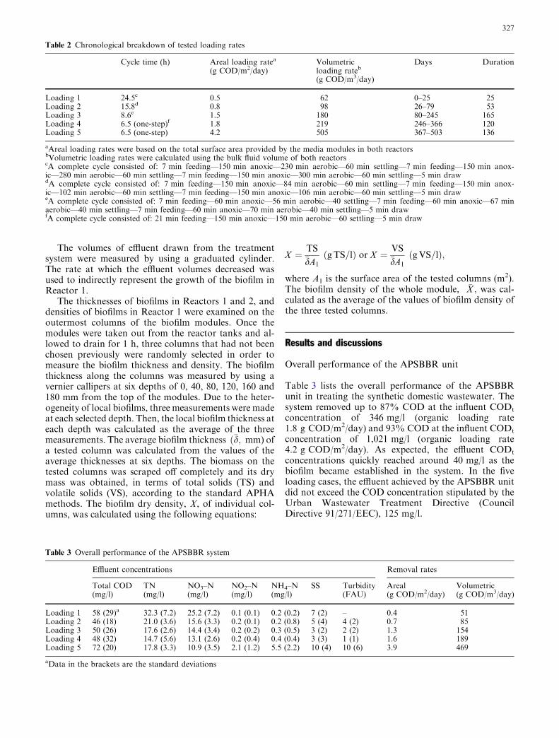
The APSBBR system was operated from 10 February2003 to 27 June 2004 and five loading rates were tested.The chronological breakdown of these loadings is pre-sented in Table 2.
The timing and operational sequence of Loading 5were the same as those of Loading 4. However, theinfluent concentrations of Loading 5 were increased toan average of 1,021 mg CODt/l, 97 mg TN/l and 54 mg/l NH4–N.
Analysis
The CODt and CODf and SS were tested using standardmethods [4]. Filtered samples were obtained by filteringthe wastewater through a Whatman GF/C glass micro-fibre filter paper (pore size 1.2 lm).
Turbidity was measured by means of the attenuatedradiation method using a HACH spectrometer. Themethod is adapted from the ISO method 7027. With25 ml of deionized water as the zero sample, 25 ml ofeffluent samples were tested at the wavelength of860 nm. The HACH spectrometer displayed the tur-bidity of effluent samples in formazin attenuation units(FAU).
Fig. 2 Biofilm modules used in the APSBBR system
Table 1 Operational strategy of the APSBBR system (three-step feeding mode)
Step feeding SBR phase Action
First feeding Fill The peristaltic pump fed Reactor 1 for a user-specified timeAnoxic Water was quiescent in Reactor 1 for a user-specified time.
The DO dropped allowing anoxic conditions to developin Reactor 1 for denitrification to occur
Aerobic Pump A began pumping water from Reactor 1 to Reactor2 until the bottom level switch in Reactor 1 was reached.Pump B began pumping 3 s later returning the water backto Reactor 1. Pump B stopped when the level switch inReactor 2 was reached. Three more seconds elapsed.This marked one complete water circulation cycle.The total number of water circulation cycles was inputtedinto the PLC programmea
Settle The water was quiescent in Reactor 1 for a user-specified timeSecond feeding Included fill, anoxic, aerobic
and settle phases, whichwere the same as those inthe first feeding
Third feeding Fill The peristaltic pump fed Reactor 1 until thetop level switch was reached
The anoxic, aerobic andsettle phases were the sameas those in the first feedingDraw The solenoid valve opened and allowed the treated effluent
to drain under gravity
aThe number of water circulation cycles in the aerobic phase was adjusted every week to ensure that the total aerobic duration was asrequired
326
The volumes of effluent drawn from the treatmentsystem were measured by using a graduated cylinder.The rate at which the effluent volumes decreased wasused to indirectly represent the growth of the biofilm inReactor 1.
The thicknesses of biofilms in Reactors 1 and 2, anddensities of biofilms in Reactor 1 were examined on theoutermost columns of the biofilm modules. Once themodules were taken out from the reactor tanks and al-lowed to drain for 1 h, three columns that had not beenchosen previously were randomly selected in order tomeasure the biofilm thickness and density. The biofilmthickness along the columns was measured by using avernier callipers at six depths of 0, 40, 80, 120, 160 and180 mm from the top of the modules. Due to the heter-ogeneity of local biofilms, three measurements were madeat each selected depth. Then, the local biofilm thickness ateach depth was calculated as the average of the threemeasurements. The average biofilm thickness ð�d; mm) ofa tested column was calculated from the values of theaverage thicknesses at six depths. The biomass on thetested columns was scraped off completely and its drymass was obtained, in terms of total solids (TS) andvolatile solids (VS), according to the standard APHAmethods. The biofilm dry density, X, of individual col-umns, was calculated using the following equations:
X ¼ TS�dA1
ðgTS=lÞ or X ¼ VS�dA1
ðgVS=lÞ;
where A1 is the surface area of the tested columns (m2).The biofilm density of the whole module, �X ; was cal-culated as the average of the values of biofilm density ofthe three tested columns.
Results and discussions
Overall performance of the APSBBR unit
Table 3 lists the overall performance of the APSBBRunit in treating the synthetic domestic wastewater. Thesystem removed up to 87% COD at the influent CODt
concentration of 346 mg/l (organic loading rate1.8 g COD/m2/day) and 93% COD at the influent CODt
concentration of 1,021 mg/l (organic loading rate4.2 g COD/m2/day). As expected, the effluent CODt
concentrations quickly reached around 40 mg/l as thebiofilm became established in the system. In the fiveloading cases, the effluent achieved by the APSBBR unitdid not exceed the COD concentration stipulated by theUrban Wastewater Treatment Directive (CouncilDirective 91/271/EEC), 125 mg/l.
Table 2 Chronological breakdown of tested loading rates
Cycle time (h) Areal loading ratea
(g COD/m2/day)Volumetricloading rateb
(g COD/m3/day)
Days Duration
Loading 1 24.5c 0.5 62 0–25 25Loading 2 15.8d 0.8 98 26–79 53Loading 3 8.6e 1.5 180 80–245 165Loading 4 6.5 (one-step)f 1.8 219 246–366 120Loading 5 6.5 (one-step) 4.2 505 367–503 136
aAreal loading rates were based on the total surface area provided by the media modules in both reactorsbVolumetric loading rates were calculated using the bulk fluid volume of both reactorscA complete cycle consisted of: 7 min feeding—150 min anoxic—230 min aerobic—60 min settling—7 min feeding—150 min anox-ic—280 min aerobic—60 min settling—7 min feeding—150 min anoxic—300 min aerobic—60 min settling—5 min drawdA complete cycle consisted of: 7 min feeding—150 min anoxic—84 min aerobic—60 min settling—7 min feeding—150 min anox-ic—102 min aerobic—60 min settling—7 min feeding—150 min anoxic—106 min aerobic—60 min settling—5 min draweA complete cycle consisted of: 7 min feeding—60 min anoxic—56 min aerobic—40 settling—7 min feeding—60 min anoxic—67 minaerobic—40 min settling—7 min feeding—60 min anoxic—70 min aerobic—40 min settling—5 min drawfA complete cycle consisted of: 21 min feeding—150 min anoxic—150 min aerobic—60 settling—5 min draw
Table 3 Overall performance of the APSBBR system
Effluent concentrations Removal rates
Total COD(mg/l)
TN(mg/l)
NO3–N(mg/l)
NO2–N(mg/l)
NH4–N(mg/l)
SS Turbidity(FAU)
Areal(g COD/m2/day)
Volumetric(g COD/m3/day)
Loading 1 58 (29)a 32.3 (7.2) 25.2 (7.2) 0.1 (0.1) 0.2 (0.2) 7 (2) – 0.4 51Loading 2 46 (18) 21.0 (3.6) 15.6 (3.3) 0.2 (0.1) 0.2 (0.8) 5 (4) 4 (2) 0.7 85Loading 3 50 (26) 17.6 (2.6) 14.4 (3.4) 0.2 (0.2) 0.3 (0.5) 3 (2) 2 (2) 1.3 154Loading 4 48 (32) 14.7 (5.6) 13.1 (2.6) 0.2 (0.4) 0.4 (0.4) 3 (3) 1 (1) 1.6 189Loading 5 72 (20) 17.8 (3.3) 10.9 (3.5) 2.1 (1.2) 5.5 (2.2) 10 (4) 10 (6) 3.9 469
aData in the brackets are the standard deviations
327

The average TN concentration entering the systemduring Loadings 1–4 was 33 mg/l. At these loadings, theeffluent NO2–N remained below 0.25 mg/l and theeffluent NH4–N was always less than 1 mg/l, indicatingthat nitrification was complete. During Loading 5, theinfluent NH4–N was 54 mg/l and effluent was 5.5 mg/l,so the nitrification efficiency was as high as 90%. TNremoval efficiency in Loadings 2–4 ranged from 36 to56%, indicating that denitrification took place to someextent. In Loading 5, TN entering the system was 97 mg/lwith the standard deviation of 2.5 mg/l. Initially, thisincreased loading caused a rise in the effluent TN.However, the treatment system recovered quickly withthe effluent TN concentration falling to an averageof 18 mg/l, which was comprised of 11 mg/l NO3–N,2 mg/l NO2–N and 5 mg/l NH4–N. These data indicatethat the system had a satisfactory nitrification efficiency(about 90%). The APSBBR system removed 56% TN atan influent TN of 33 mg/l and 82% at an influent TNconcentration of 97 mg/l.
Nitrogen was removed from the system in two ways.One was that nitrogen in the wastewater was used as thenitrogen source for the synthesis of new biomass. TheAPSBBR system was found to yield 0.17 g VS/g CODremoval when treating dairy wastewater [unpublisheddata], much less than the sludge yield in conventionalactivated sludge systems. During the 18-month experi-ment, waste sludge that built up in the bottom of thereactor tanks was only desludged five times.
The second way to remove nitrogen from wastewaterwas denitrification. During the anoxic phase, DOdropped to around zero, which was beneficial for deni-trification; while, during the aerobic phase, DO in-creased to more than 5 mg/l, which favouredcarbonaceous oxidation and nitrification.
From Table 3, it is found that the APSBBR systemperformed very well with regard to SS and turbidity ofthe effluent. For Loadings 1–4, SS never exceeded
10 mg/l and turbidity never exceeded 10 FAU. Both SSand turbidity began to rise in the final loading phase, butneither exceeded 20 mg/l nor 20 FAU, respectively. TheUrban Wastewater Treatment Directive requires thatthe concentration of SS must be maintained at, or below,35 mg/l, and this limit was never exceeded by the APS-BBR unit.
Biofilm growth
Figure 3 shows the profiles of biofilm thickness inReactors 1 and 2 along the depth of biofilm modules atthe end of Loading 3. It can be found that the biofilmthickness in Reactor 2 was much lower than in Reactor1, which was due to the difference in substrate loadingsand growth conditions in the two reactors. The freshfeed was pumped to Reactor 1 and the biofilm inReactor 1 participated in the anoxic digestion anddenitrification, aerobic carbonaceous oxidation andnitrification, and the settling phase, but, the biofilm inReactor 2 only contributed to the aerobic carbonaceousoxidation and nitrification. Therefore, the COD removaltaking place in Reactor 1 was much greater than inReactor 2. It was estimated that Reactor 1 contributedabout 60% of CODt removal but Reactor 2 just about40%. Some researchers have observed similar phenom-ena in their studies. Increasing substrate concentrationsfavours an increase in active biofilm thickness [5].Wasche et al. [6] found in their study that the maximumbiofilm thickness was observed at a substrate loading of10 g glucose/m2/day but a compact and stable biofilmwas grown at substrate loadings not higher than2.5 g glucose/m2/day.
It was observed that the biofilm in Reactor 2 wassticky and compact while a loose biofilm grew inReactor 1. The biofilm in Reactor 2 was only involved inthe aerobic phase, and it was exposed to the air for more
0
20
40
60
80
100
120
140
160
180
0 0.5 1 1.5Biofilm thickness (mm)
Dep
th (
mm
)
2
Reactor 1
Reactor 2
Top of the modules
Bottom of the modules
Fig. 3 Profile of biofilmthickness along biofilm modulesat the end of Loading 3
328

than 85% of the operational time including when thewastewater was quiescent in the anoxic, settle and drawphases in Reactor 1.
Local biofilms in Reactor 1 were thicker at deeper testpoints. This could have occurred because the deeper testpoints encountered higher substrate loading rates as theinfluent was fed to Reactor 1 at the bottom of the tank,just beneath the biofilm module.
The biofilm thickness in Reactor 1 varied, in therange of 0.3 mm at the top to 1.7 mm at the bottom ofthe biofilm module. Normally, the oxygen penetrationdepth in a biofilm is just a small portion of the wholebiofilm thickness. It was found that for a nitrifyingbiofilm, O2 penetrated to depths of 50–150 lm [7]. Theoxygen diffusion layer of a biofilm attached on a par-tially submerged rotating biological contactor was ob-served to be 70 lm thick [8]. Therefore, an anaerobiccondition could have existed on the inside of the biofilmin Reactor 1 where denitrification could have takenplace. In Reactor 2, the biofilm thickness ranged from0.0 mm at the top to 0.8 mm at the bottom of the bio-film module.
The biofilm density in Reactor 1 was equal to27 g VS/l, which was consistent with the range of5–100 g/l for carbonaceous oxidation biofilm given byTipadis [9] for RBCs.
The replacement of water by new biomass on thebiofilm module and reactor walls led to the decrease ofthe effluent volume, which is shown in Fig. 4. It can beseen from Fig. 4 that the decease of the effluent volumewas slow during Loadings 2 and 3 but was faster inLoadings 4 and 5 with higher organic loading rates. Thisshows higher biofilm growth rates in Loadings 4 and 5.Therefore, it can be concluded that the biofilm growthincreased with increasing organic loading rates. This ledto high fractions of denitrifiers in the biofilms and anoxicconditions deep in the biofilms due to the partial pene-tration of oxygen. As a consequence, nitrogen removalefficiency increased when the influent loading rate wasincreased.
Conclusion
This study investigated the performance of a newlydeveloped APSBBR system in treating synthetic domes-tic wastewater. The following conclusions were obtained:
1. The system removed 87% COD at the influent CODconcentration of 346 mg/l (the areal loading rate1.8 g COD/m2/day) and 93% COD at the influentCOD concentration of 1,021 mg/l (the areal loadingrate 4.2 g COD/m2/day).
2. The APSBBR system removed 56% TN at influentTN of 33 mg/l and 82% TN at influent TN concen-tration of 97 mg/l.
3. The effluent from the APSBBR system satisfied theEuropean Wastewater Treatment Directive.
4. The biofilm thickness in Reactor 1, 0.3–1.7 mm, wasmuch higher than that in Reactor 2, 0–0.8 mm. Thedifference of biofilms in Reactors 1 and 2 was due todifferent substrate loadings and growth conditions inthe two reactors. The biofilm grew quicker as theloading rates increased.
Acknowledgements The authors are very grateful to EnterpriseIreland for financial support and to RPS-MCOS Ltd. for the M.C.O’Sullivan Postgraduate Scholarship awarded to Edmond O’Reillyin 2002.
References
1. Smith D, O’Neill N, Doris Y, Moriarty J (2004) Urban wastewater discharges in Ireland with population equivalent greaterthan 500 persons: a report for the years 2002 and 2003. IrishEPA, Ireland
2. Boller M (1997) Small wastewater treatment plants—a challengeto wastewater engineers. Water Sci Technol 35:1–12
3. Odegaard H, Rusten B (1980) Nitrogen removal in rotatingbiological contactors without the use of external carbonaceoussource. In: Proceedings of the first national symposium/work-shop on rotating biological contactor technology, vol. 1.Champion, Pennsylvania, pp 1301–1317
0
1
2
3
4
5
6
7
8
9
10
0 50 100 150 200 250 300 350 400 450 500
Time (days)
Eff
luen
t V
olu
me
(lit
res)
Loading 3 Loading 4 Loading 5Loading 2
Loading 1 Fig. 4 Measured effluentvolume versus time
329

4. APHA (1995) Standard methods for the examination of waterand wastewater, 19th edn. American Public Health Association,Washington
5. Tanyolac A, Beyenal H (1996) Effectiveness factor for a hollow-fiber biofilm reactor at maximum substrate consumption. ChemEng J 62:149–154
6. Wasche S, Horn H, Hempel DC (2002) Influence of growthconditions on biofilm development and mass transfer at thebulk/biofilm interface. Water Res 36:4775–4784
7. Schramm A, Larsen LH, Revsbech NP, Ramsing NB, AmannR, Schleifer K-H (1996) Structure and function of a nitrifying
biofilm as determined by in situ hybridization and the use ofmicroelectrodes. Appl Environ Microbiol 62:4641–4647
8. Nishidome K, Kusuda T, Watanabe Y, Yamauchi M, Mihara M(1994) Determination of oxygen transfer rate to a rotating bio-logical contactor by microelectrode measurement. Water SciTechnol 29(10–11):471–477
9. Tipadis G (1991) Mathematical model for wastewater treatmentby the rotating biological contactor process. PhD Thesis,Imperial College, University of London
330