Embed Size (px)
Citation preview
Attached Growth Biological WW treatment Systems
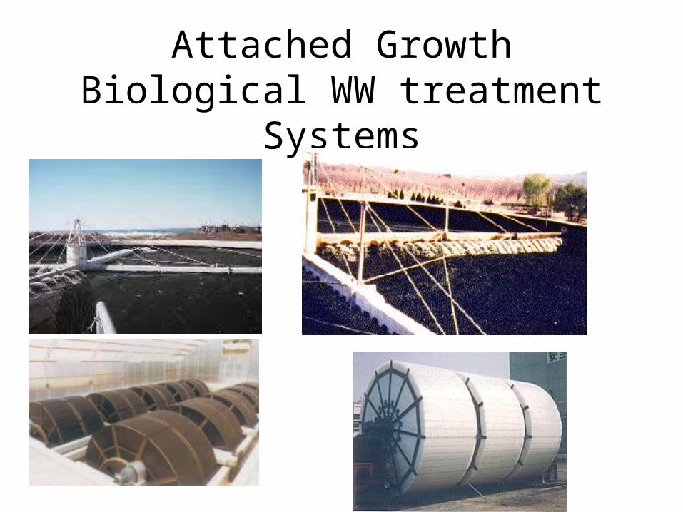
Biofilm Systems• Biofilm
– a biological slime layer– bacteria in biofilm
degrade organics– biofilm will develop
on almost anything
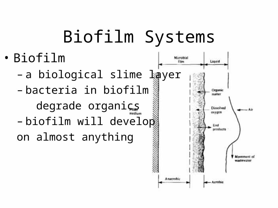
Types of Biofilm Systems
• Trickling filters
• Rotating biological contactors
• Fluidized bed reactors
• Biofilters
• Wetlands systems
• Sequencing batch biofilm reactors
(many of these can be aerobic or anaerobic)
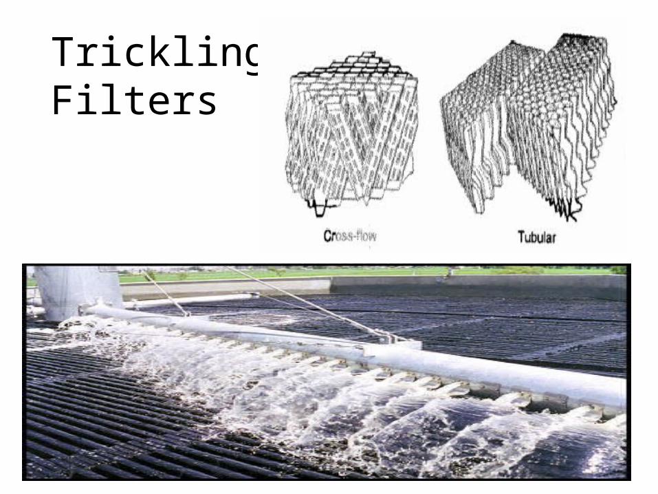
TricklingFilters
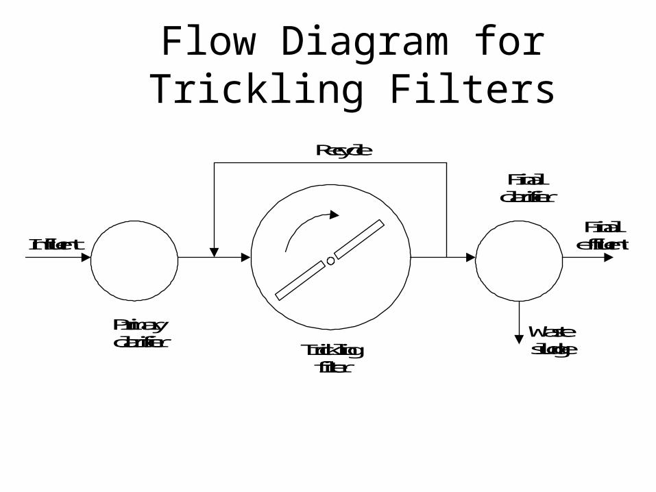
Flow Diagram for Trickling Filters
Recycle
Primaryclarifier Trickling
filter
Finalclarifier
Wastesludge
FinaleffluentInfluent
Trickling Filters
• Not a true filtering or sieving process
• Material only provides surface on which bacteria to grow
• Can use plastic media– lighter - can get deeper beds (up to 12 m)– reduced space requirement– larger surface area for growth– greater void ratios (better air flow)– less prone to plugging by accumulating slime
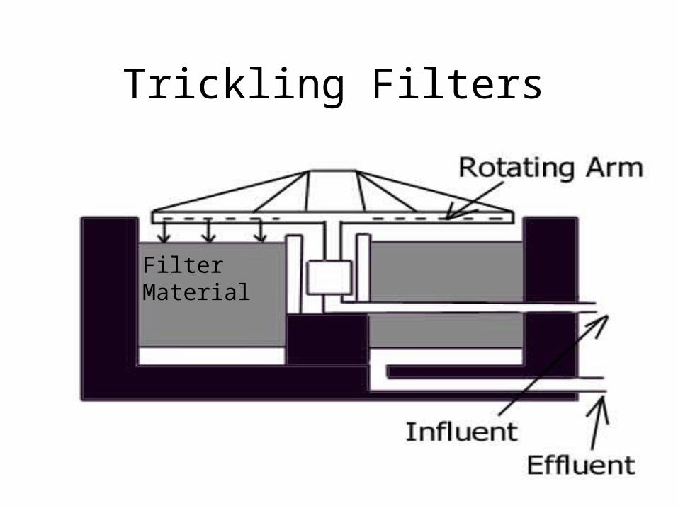
Trickling Filters
Filter Material
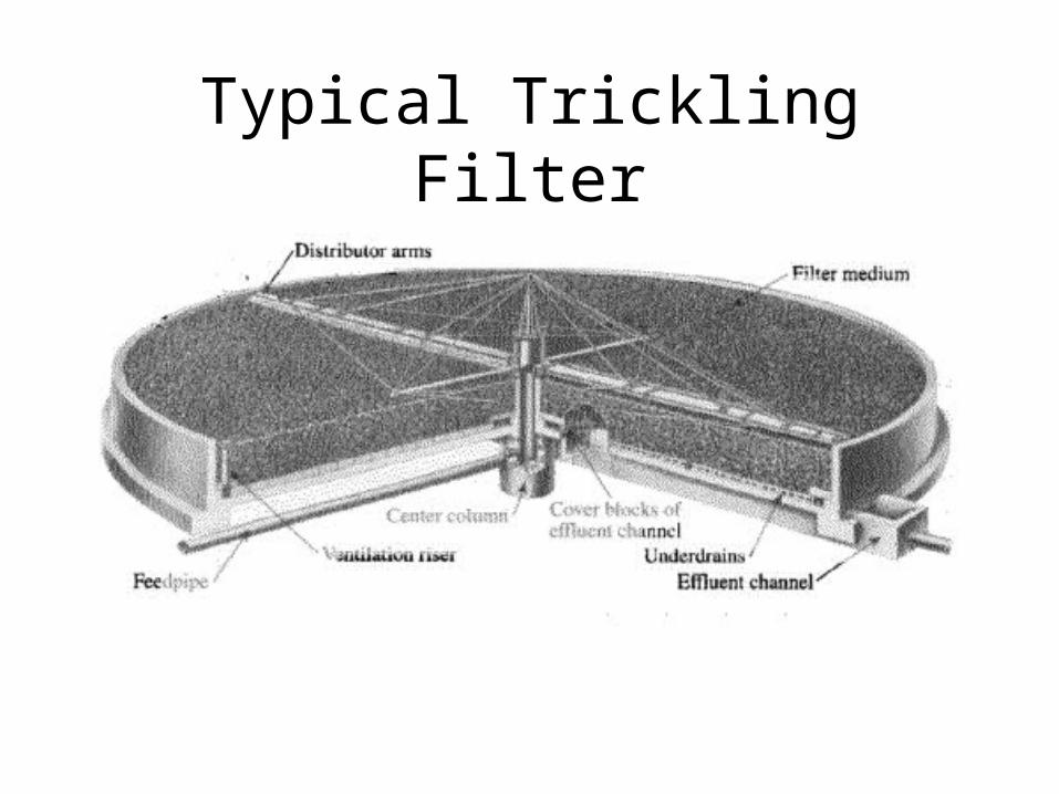
Typical Trickling Filter
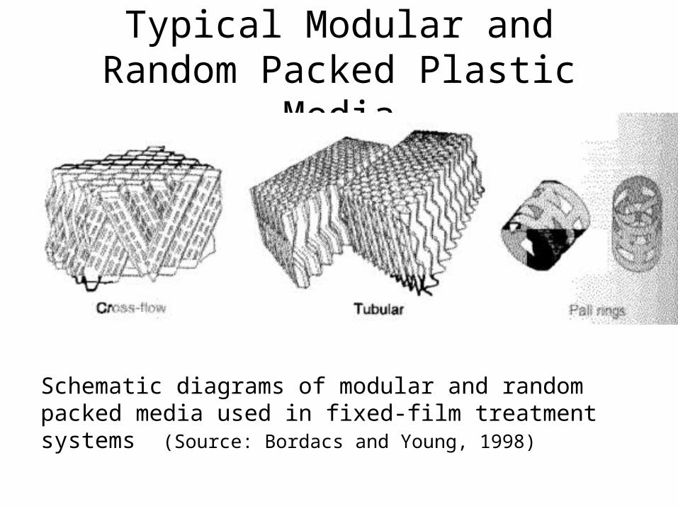
Typical Modular and Random Packed Plastic Media
Schematic diagrams of modular and random packed media used in fixed-film treatment systems (Source: Bordacs and Young, 1998)

Random Packing
Leon
ard
W. C
asso
n, P
h.D
., P.
E., D
EELe
onar
d W
. Cas
son,
Ph.
D.,
P.E.
, DEE
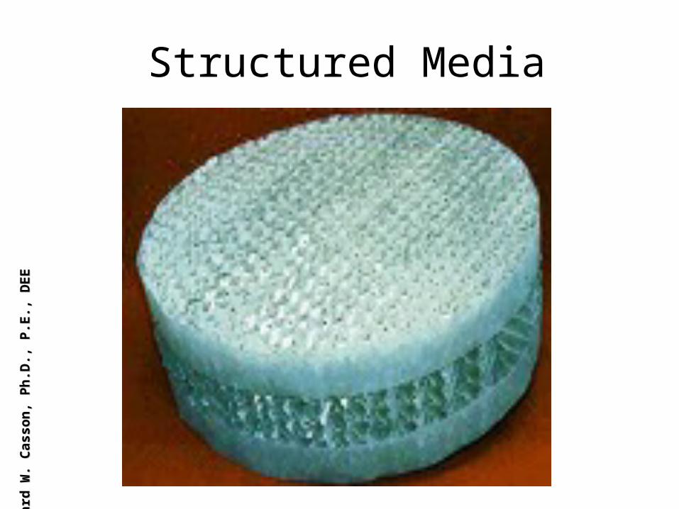
Structured MediaLe
onar
d W
. Cas
son,
Ph.
D.,
P.E.
, DEE
Leon
ard
W. C
asso
n, P
h.D
., P.
E., D
EE
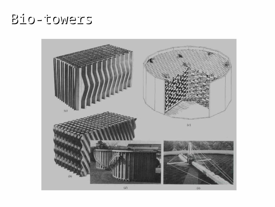
Bio-towersBio-towers
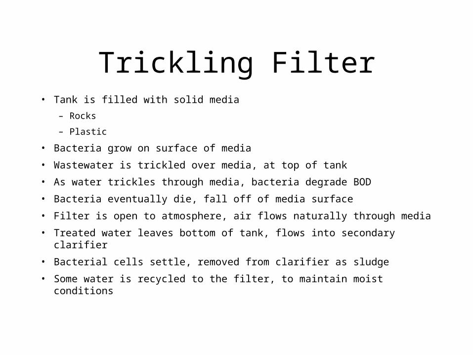
Trickling Filter• Tank is filled with solid media
– Rocks
– Plastic
• Bacteria grow on surface of media
• Wastewater is trickled over media, at top of tank
• As water trickles through media, bacteria degrade BOD
• Bacteria eventually die, fall off of media surface
• Filter is open to atmosphere, air flows naturally through media
• Treated water leaves bottom of tank, flows into secondary clarifier
• Bacterial cells settle, removed from clarifier as sludge
• Some water is recycled to the filter, to maintain moist conditions
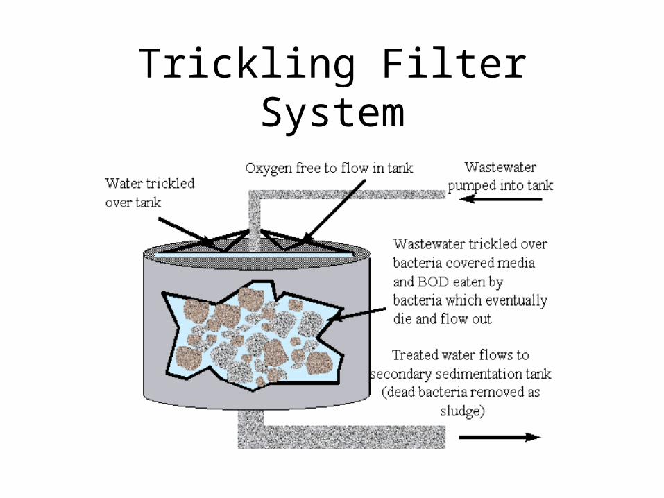
Trickling Filter System

Trickling Filter Process
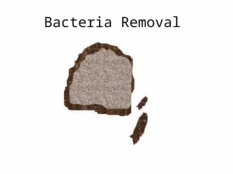
Bacteria Removal
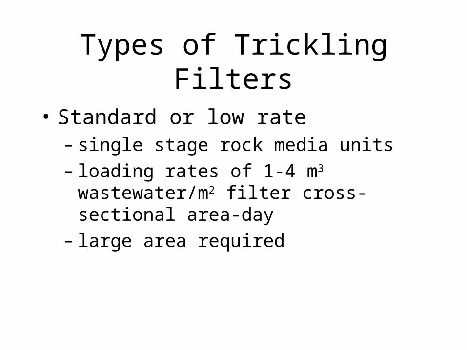
Types of Trickling Filters
• Standard or low rate– single stage rock media units– loading rates of 1-4 m3 wastewater/m2 filter
cross-sectional area-day– large area required

Types of Trickling Filters
• High rate– single stage or two-stage rock media units– loading rates of 10-40 m3 wastewater/m2 filter
cross-sectional area-day– re-circulation ratio 1-3

Types of Trickling Filters• Super rate
– synthetic plastic media units• modules or random packed
• specific surface areas 2-5 times greater than rock
• much lighter than rocks
• can be stacked higher than rocks
– loading rates of 40-200 m3 wastewater/m2 filter cross-sectional area-day
– plastic media depths of 5-10 m
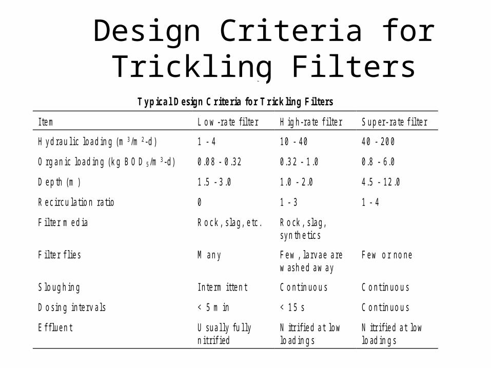
Design Criteria for Trickling FiltersT a b le 10 .5
T y p ic a l D e s ig n C r ite ria fo r T r ic k li ng F il te rs
Ite m L o w -ra te filte r H ig h-ra te f ilte r S up er- ra te f ilte r
H yd ra u l ic loa d in g (m 3/m 2-d ) 1 - 4 10 - 40 40 - 20 0
O rg a n ic loa d in g (k g B O D 5/m 3-d) 0 .0 8 - 0 .32 0.3 2 - 1 .0 0.8 - 6.0
D e p th (m ) 1 .5 - 3 .0 1.0 - 2.0 4.5 - 12 .0
R e c irc u la tio n ra tio 0 1 - 3 1 - 4
F ilte r m e d ia R o c k , s la g, e tc . R o ck , s la g,syn th e tic s
F ilte r f lie s M a n y Fe w , la rva e a rew ash e d a w a y
Fe w o r no ne
S lo ug h in g I nte rm itte n t C o nt in uo u s C o nt in uo u s
D o sin g inte rv a ls < 5 m in < 1 5 s C o nt in uo u s
E f flue n t U sua l ly fu l lyn it rif ied
N itr ifie d a t lowlo ad in g s
N itr ifie d a t lowlo ad in g s
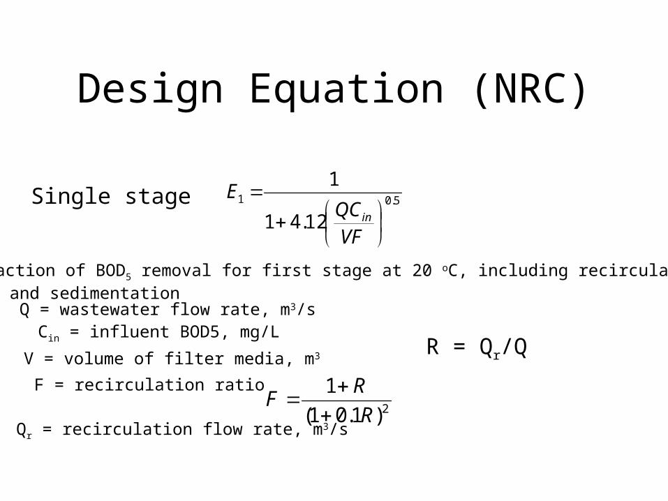
Design Equation (NRC)
Single stage 5.01
12.41
1
VF
QCE
in
E1 = fraction of BOD5 removal for first stage at 20 oC, including recirculation and sedimentationQ = wastewater flow rate, m3/sCin = influent BOD5, mg/L
V = volume of filter media, m3
F = recirculation ratio2)1.01(
1
R
RF
R = Qr/Q
Qr = recirculation flow rate, m3/s
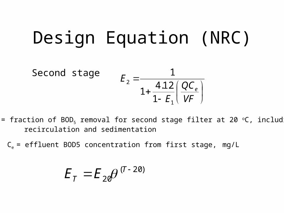
Design Equation (NRC)
Second stage
VFQC
E
Ee
1
2
112.4
1
1
E2 = fraction of BOD5 removal for second stage filter at 20 oC, including recirculation and sedimentation
Ce = effluent BOD5 concentration from first stage, mg/L
)20(20
TT EE
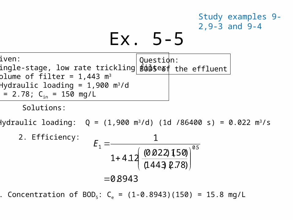
Ex. 5-5Given:Single-stage, low rate trickling filterVolume of filter = 1,443 m3
Hydraulic loading = 1,900 m3/dF = 2.78; Cin = 150 mg/L
Question:BOD5 of the effluent
Solutions:
1. Hydraulic loading: Q = (1,900 m3/d) (1d /86400 s) = 0.022 m3/s
2. Efficiency:
8943.0
)78.2)(1443()150)(022.0(
12.41
15.01
E
3. Concentration of BOD5: Ce = (1-0.8943)(150) = 15.8 mg/L
Study examples 9-2,9-3 and 9-4
Rotating Biological Contactor
Rotating Biological Contactors, commonly called RBC’s, are used in
wastewater treatment plants (WWTPs). The primary function of these bio-reactors at WWTPs is the
reduction organic matter.
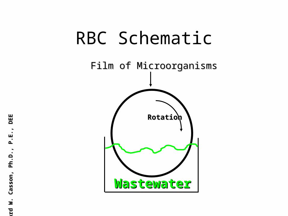
RBC Schematic
WastewaterWastewater
Film of MicroorganismsFilm of Microorganisms
RotationRotation
Leon
ard
W. C
asso
n, P
h.D
., P.
E., D
EELe
onar
d W
. Cas
son,
Ph.
D.,
P.E.
, DEE
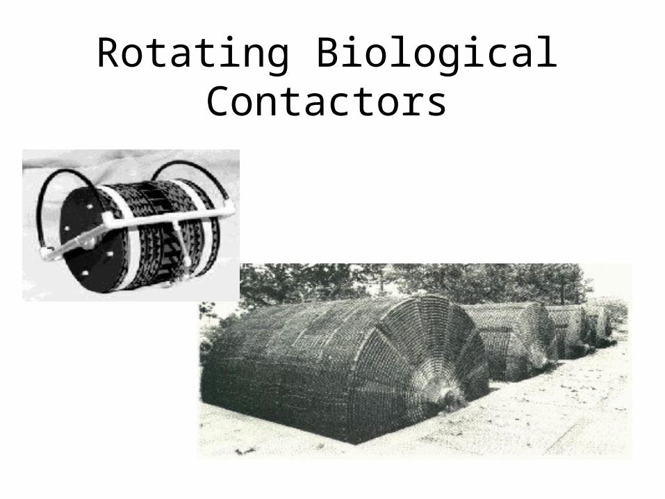
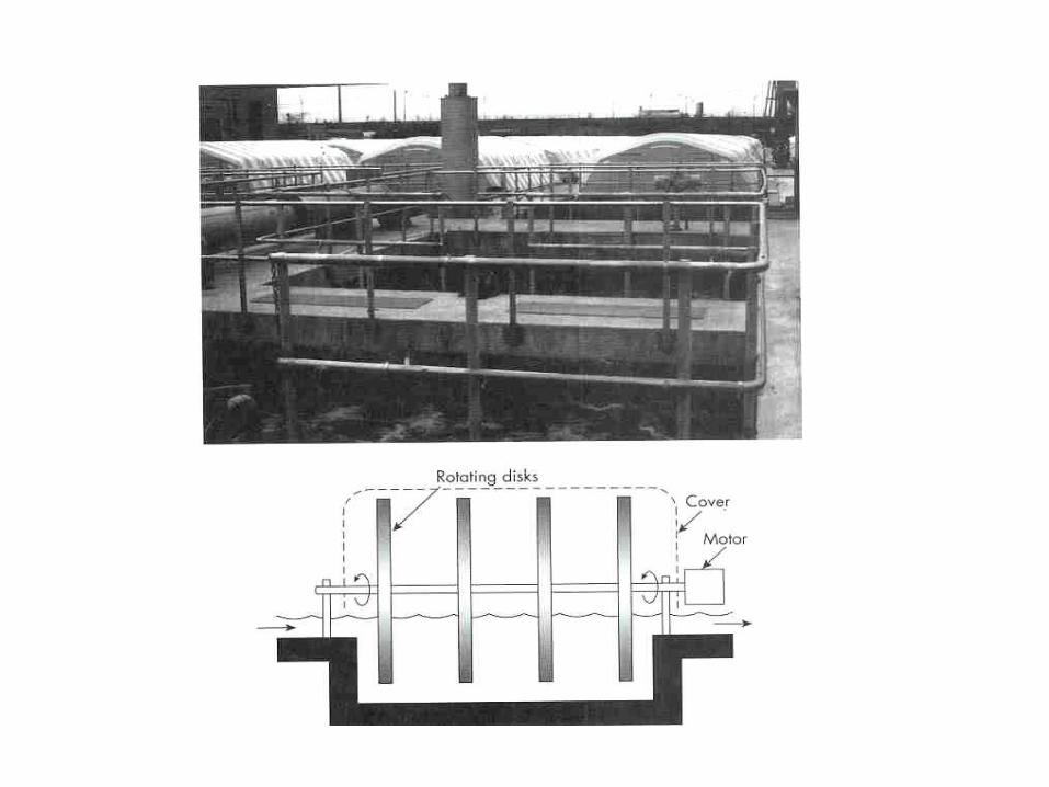
Rotating Biological Contactors
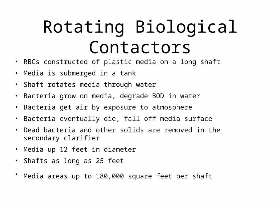
Rotating Biological Contactors• RBCs constructed of plastic media on a long shaft
• Media is submerged in a tank
• Shaft rotates media through water
• Bacteria grow on media, degrade BOD in water
• Bacteria get air by exposure to atmosphere
• Bacteria eventually die, fall off media surface
• Dead bacteria and other solids are removed in the secondary clarifier
• Media up 12 feet in diameter
• Shafts as long as 25 feet
• Media areas up to 180,000 square feet per shaft
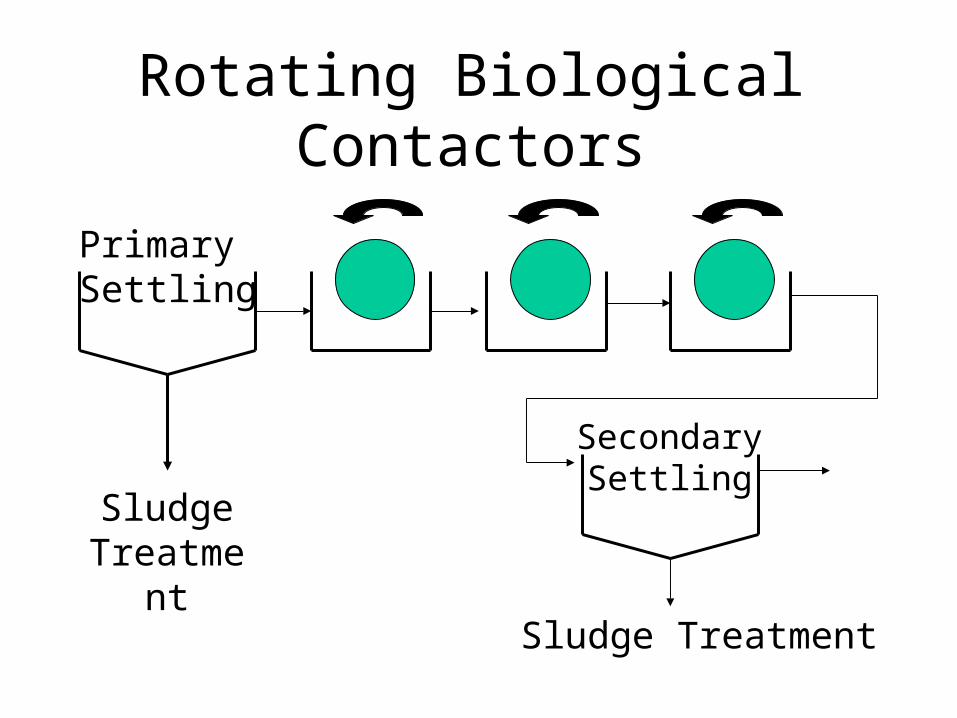
Rotating Biological Contactors
PrimarySettling
SludgeTreatme
nt
SecondarySettling
Sludge Treatment
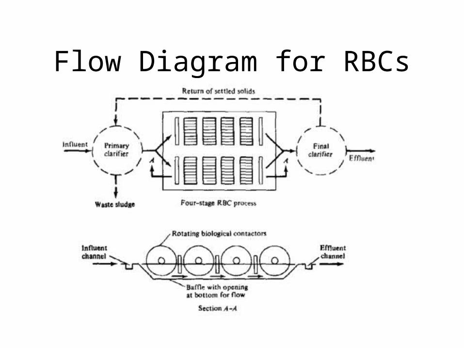
Flow Diagram for RBCs
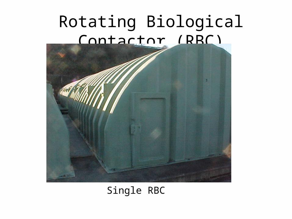
Rotating Biological Contactor (RBC)
Single RBC
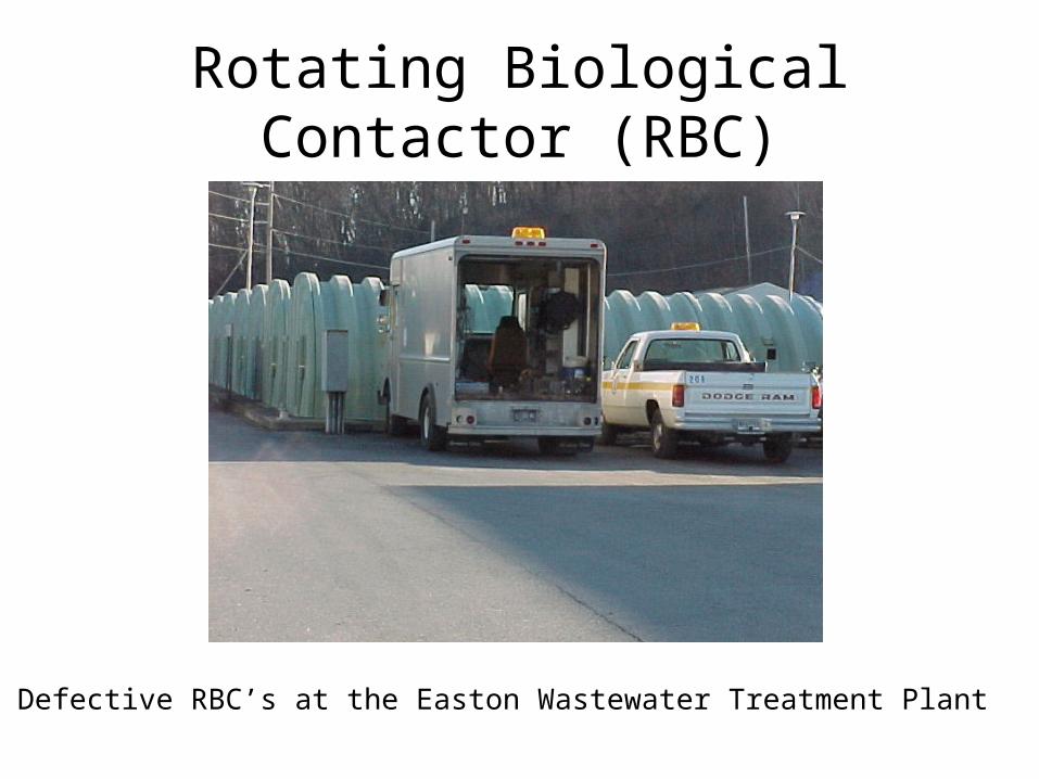
Rotating Biological Contactor (RBC)
Defective RBC’s at the Easton Wastewater Treatment Plant
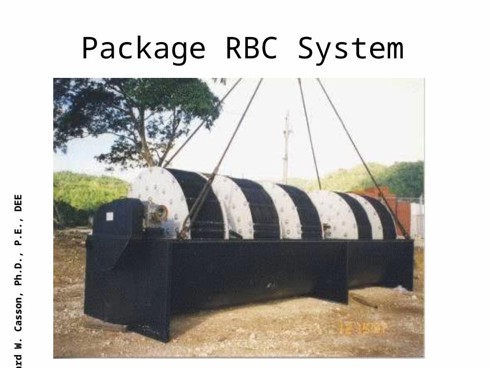
Package RBC SystemLe
onar
d W
. Cas
son,
Ph.
D.,
P.E.
, DEE
Leon
ard
W. C
asso
n, P
h.D
., P.
E., D
EE