Embed Size (px)
Citation preview
The South African Institute of Mining and Metallurgy International Symposium on Stability of Rock Slopes Ricardo Sepulveda
Page 265
SLOPE OPTIMIZATION AT ESCONDIDA NORTE OPEN PIT
Mr. Manuel Rapiman Chief Geotechnical Engineering, Minera Escondida Ltd.
BHP Billiton Base Metals, Chile Mr. Ricardo Sepulveda
Geotechnical Consultant A. Karzulovic & Assoc. Ltd., Chile
ABSTRACT
The feasibility study of Escondida Norte (ENorte), recommended a slope angle design for the Final Pit. But, according to the experience obtained with the slope adjacent to the West wall of ENorte, in which Compañia Minera Zaldívar (CMZ) gained in its phase 4, a slope of similar geotechnical characteristics will be exposed in the West Wall of Phase 1 (Premine) and of the Final Pit, with an interramp angle 53º and with very good stability results.
In this regard, Minera Escondida Ltd. (MEL) performed a study of the slope angles for the phases mentioned and according to this delivered the results of this evaluation, the recommendations and/or the necessary conclusions in the design to ensure that the slopes are stable enough and may enable safe operational management of them.
INTRODUCTION
The objective of the study developed, is to perform a revision and evaluation of the slope angles for Phase 1 (Premine) and the West Wall of the Final Pit of ENorte pit.
The work described in this paper is directed towards the stability analyses of slopes, evaluating the degree of stability for potential slides on failure surfaces. The details of the stability analyses developed by limit equilibrium methods are included.
The present work is supported by the following data and report sources:
Plane and vertical sections design of ENorte for Phase 1 and Final Pit.
(a) Geotechnical report used in the study performed for CMZ, related to the in-teraction between Phase 4 and the Final Pit of ENorte of MEL.
(b) Geotechnical report of previous studies for ENorte.
(c) Technical data provided by MEL, regarding the geotechnical properties of the geotechnical units present in the pit and the groundwater level in the ENorte sector.
GENERAL CONSIDERATIONS
The good results obtained from the analyses, according to the point of view of the sta-bility of slopes during the feasibility study developed by MEL for Project ENorte, and
The South African Institute of Mining and Metallurgy International Symposium on Stability of Rock Slopes Ricardo Sepulveda
Page 266
N
P01P01--N1N1
P16P16--N1N1
P03P03--N1N1
P04P04--N1N1
P17P17--N1N1
P15P15--N1N1
N
P01P01--N1N1
P16P16--N1N1
P03P03--N1N1
P04P04--N1N1
P17P17--N1N1
P15P15--N1N1
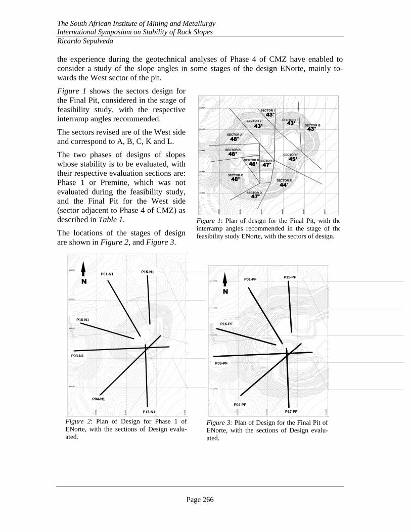
Figure 2: Plan of Design for Phase 1 of ENorte, with the sections of Design evalu-ated.
E-1
750
0
E-1
800
0
E-1
850
0
E-1
900
0
E-1
950
0
E-2
0000
N-113000
N-113500
N-114000
N-114500
N-115000
SECTOR D
SECTOR C
SECTOR B
SECTOR A
SECTOR J
SECTOR I
SECTOR E
SECTOR H
SECTOR F
SECTOR G
SECTOR LSECTOR K
48°
48°
48°
43°
43°
43°
43°
45°
44°
47°
47°48°
E-1
750
0
E-1
800
0
E-1
850
0
E-1
900
0
E-1
950
0
E-2
0000
N-113000
N-113500
N-114000
N-114500
N-115000
SECTOR D
SECTOR C
SECTOR B
SECTOR A
SECTOR J
SECTOR I
SECTOR E
SECTOR H
SECTOR F
SECTOR G
SECTOR LSECTOR K
48°
48°
48°
43°
43°
43°
43°
45°
44°
47°
47°48°
Figure 1: Plan of design for the Final Pit, with theinterramp angles recommended in the stage of thefeasibility study ENorte, with the sectors of design.
E-1
750
0
E-1
80
00
E-1
85
00
E-1
90
00
N-113000
N-113500
N-114000
N-114500
N-115000
N
P01P01--PFPF
P16P16--PFPF
P03P03--PFPF
P04P04--PFPF
P17P17--PFPF
P15P15--PFPF
E-1
750
0
E-1
80
00
E-1
85
00
E-1
90
00
N-113000
N-113500
N-114000
N-114500
N-115000
N
P01P01--PFPF
P16P16--PFPF
P03P03--PFPF
P04P04--PFPF
P17P17--PFPF
P15P15--PFPF
Figure 3: Plan of Design for the Final Pit of ENorte, with the sections of Design evalu-ated.
the experience during the geotechnical analyses of Phase 4 of CMZ have enabled to consider a study of the slope angles in some stages of the design ENorte, mainly to-wards the West sector of the pit.
Figure 1 shows the sectors design for the Final Pit, considered in the stage of feasibility study, with the respective interramp angles recommended.
The sectors revised are of the West side and correspond to A, B, C, K and L.
The two phases of designs of slopes whose stability is to be evaluated, with their respective evaluation sections are: Phase 1 or Premine, which was not evaluated during the feasibility study, and the Final Pit for the West side (sector adjacent to Phase 4 of CMZ) as described in Table 1.
The locations of the stages of design are shown in Figure 2, and Figure 3.
The South African Institute of Mining and Metallurgy International Symposium on Stability of Rock Slopes Ricardo Sepulveda
Page 267
Table 1
STAGES OF DESIGN CONSIDERED IN THIS STUDY
Stage Maximum Slope Height (m) Vertical Section(s)
Phase1 364 P01-N1, P03-N1, P04-N1, P15-N1, P16-N1, P17-N1
Final Pit 505 P01-FP, P03-PF, P04-FP, P15-PF, P16-FP, P17-FP
This study is also based on the following considerations and suggestions:
• The following data was provided by the feasibility study of ENorte:
(a) Geological report, location and geometry of the geological contacts.
(b) Structural systems, limits of structural domains, location of fault zones.
(c) Hydrogeological report.
(d) The geotechnical parameters of the rock mass and structures present in the sec-tions of analyses.
(e) For the angle of the face of the benches the same criteria in the feasibility study of project ENorte is used. This is supported by the report of Minera Escondida Limited (March 2003): Feasibility Study Escondida Norte.
• The designs suggested here are valid, considering all the previous suggestions de-scribed.
The evaluation and/or optimization were performed using the limit equilibrium analysis method for the sections previously determined for the pit in design for Phase 1 and Final Pit.
In every one of the cases described, 6 geotechnical sections design were analyzed. The sections had priority over the side adjacent to the pit of Phase 4 of CMZ, since it is over that side where the final wall of the pit ENorte was first determined. It operationally interacts with pit CMZ.
For the stability analyses the limit equilibrium methods (Program SLIDE, ROC-SCIENCE (2003), Geomechanics Software & Research) were used, and, aiming to de-termine the sliding safety factor, FS, the option to analyze by the General Limit Equilib-rium method (GLE) was used. The Probability of Failure, PF was evaluated according to recent suggestions from Duncan (2000).
GEOLOGY & GEOTECHNICS
Regarding the points described in General Considerations, the geological and geo-technical reports are the same ones used during the feasibility study of Project ENorte, including the following aspects:
� Location and geometry of the geological contacts
� Main failure systems
The South African Institute of Mining and Metallurgy International Symposium on Stability of Rock Slopes Ricardo Sepulveda
Page 268
� Phreatic level location
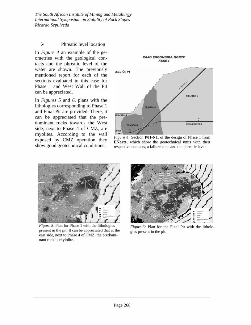
In Figure 4 an example of the ge-ometries with the geological con-tacts and the phreatic level of the water are shown. The previously mentioned report for each of the sections evaluated in this case for Phase 1 and West Wall of the Pit can be appreciated.
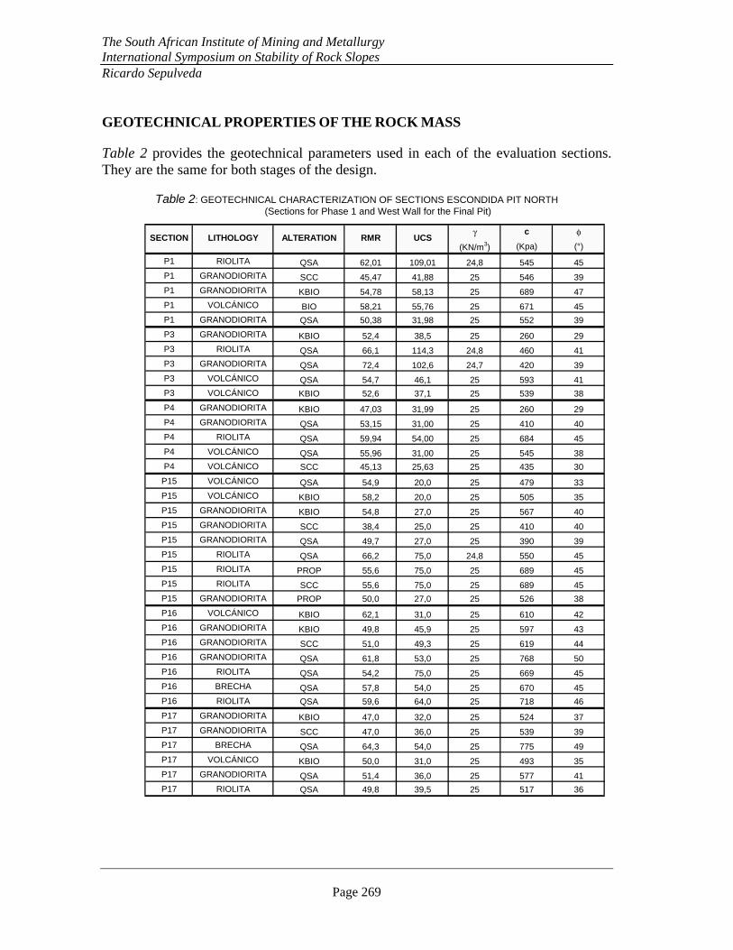
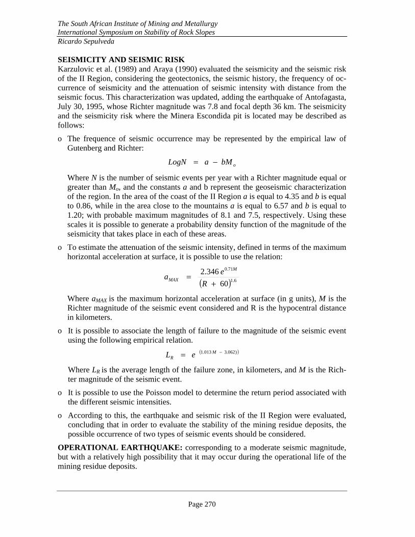
In Figures 5 and 6, plans with the lithologies corresponding to Phase 1 and Final Pit are provided. There, it can be appreciated that the pre-dominant rocks towards the West side, next to Phase 4 of CMZ, are rhyolites. According to the wall exposed by CMZ operation they show good geotechnical conditions.
RAJO ESCONDIDA NORTE RAJO ESCONDIDA NORTE
FASE IFASE I
SECCIÓN P1
RIOL(QSA)-1
GRD(QSA)-2
GRD(QSA)-8
RIOL(QSA)-1
C(BIO)-5
ZONA FALLA
NIVEL FREÁTICO
RAJO ESCONDIDA NORTE RAJO ESCONDIDA NORTE
FASE IFASE I
SECCIÓN P1
RIOL(QSA)-1
GRD(QSA)-2
GRD(QSA)-8
RIOL(QSA)-1
C(BIO)-5
ZONA FALLA
NIVEL FREÁTICO
Figure 4: Section P01-N1, of the design of Phase 1 from ENorte, which show the geotechnical units with their respective contacts, a failure zone and the phreatic level.
Sector E
Sector B
Sector A
Sector C
Sector L
Sector K
Sector F
Sector J
Granodiorita
Volcánico
Grabas
Brecha
Granodiorita Complex.Riolita
Sector E
Sector B
Sector A
Sector C
Sector L
Sector K
Sector F
Sector J
Granodiorita
Volcánico
Grabas
Brecha
Granodiorita Complex.Riolita
Granodiorita
Volcánico
Grabas
Brecha
Granodiorita Complex.Riolita
Figure 5: Plan for Phase 1 with the lithologies present in the pit. It can be appreciated that at the east side, next to Phase 4 of CMZ, the predomi-nant rock is rhylolite.
Sector A
Sector I
Sector G
Sector JSector H
Sector F
Sector E
Sector L
Sector B
Sector K
Sector C
Sector D
P_17
P_3
P_16
P_4
P_1
P_15
Granodiorita
Volcánico
Grabas
Brecha
Granodiorita Complex.Riolita
Sector A
Sector I
Sector G
Sector JSector H
Sector F
Sector E
Sector L
Sector B
Sector K
Sector C
Sector D
P_17
P_3
P_16
P_4
P_1
P_15
Sector A
Sector I
Sector G
Sector JSector H
Sector F
Sector E
Sector L
Sector B
Sector K
Sector C
Sector D
P_17
P_3
P_16
P_4
P_1
P_15
Granodiorita
Volcánico
Grabas
Brecha
Granodiorita Complex.Riolita
Granodiorita
Volcánico
Grabas
Brecha
Granodiorita Complex.Riolita
Figure 6: Plan for the Final Pit with the litholo-gies present in the pit.
The South African Institute of Mining and Metallurgy International Symposium on Stability of Rock Slopes Ricardo Sepulveda
Page 269
GEOTECHNICAL PROPERTIES OF THE ROCK MASS
Table 2 provides the geotechnical parameters used in each of the evaluation sections. They are the same for both stages of the design.
Table 2: GEOTECHNICAL CHARACTERIZATION OF SECTIONS ESCONDIDA PIT NORTH (Sections for Phase 1 and West Wall for the Final Pit)
γ c φ
(KN/m3) (Kpa) (°)
P1 RIOLITA QSA 62,01 109,01 24,8 545 45
P1 GRANODIORITA SCC 45,47 41,88 25 546 39
P1 GRANODIORITA KBIO 54,78 58,13 25 689 47
P1 VOLCÁNICO BIO 58,21 55,76 25 671 45
P1 GRANODIORITA QSA 50,38 31,98 25 552 39
P3 GRANODIORITA KBIO 52,4 38,5 25 260 29
P3 RIOLITA QSA 66,1 114,3 24,8 460 41
P3 GRANODIORITA QSA 72,4 102,6 24,7 420 39
P3 VOLCÁNICO QSA 54,7 46,1 25 593 41
P3 VOLCÁNICO KBIO 52,6 37,1 25 539 38
P4 GRANODIORITA KBIO 47,03 31,99 25 260 29
P4 GRANODIORITA QSA 53,15 31,00 25 410 40
P4 RIOLITA QSA 59,94 54,00 25 684 45
P4 VOLCÁNICO QSA 55,96 31,00 25 545 38
P4 VOLCÁNICO SCC 45,13 25,63 25 435 30
P15 VOLCÁNICO QSA 54,9 20,0 25 479 33
P15 VOLCÁNICO KBIO 58,2 20,0 25 505 35
P15 GRANODIORITA KBIO 54,8 27,0 25 567 40
P15 GRANODIORITA SCC 38,4 25,0 25 410 40
P15 GRANODIORITA QSA 49,7 27,0 25 390 39
P15 RIOLITA QSA 66,2 75,0 24,8 550 45
P15 RIOLITA PROP 55,6 75,0 25 689 45
P15 RIOLITA SCC 55,6 75,0 25 689 45
P15 GRANODIORITA PROP 50,0 27,0 25 526 38
P16 VOLCÁNICO KBIO 62,1 31,0 25 610 42
P16 GRANODIORITA KBIO 49,8 45,9 25 597 43
P16 GRANODIORITA SCC 51,0 49,3 25 619 44
P16 GRANODIORITA QSA 61,8 53,0 25 768 50
P16 RIOLITA QSA 54,2 75,0 25 669 45
P16 BRECHA QSA 57,8 54,0 25 670 45
P16 RIOLITA QSA 59,6 64,0 25 718 46
P17 GRANODIORITA KBIO 47,0 32,0 25 524 37
P17 GRANODIORITA SCC 47,0 36,0 25 539 39
P17 BRECHA QSA 64,3 54,0 25 775 49
P17 VOLCÁNICO KBIO 50,0 31,0 25 493 35
P17 GRANODIORITA QSA 51,4 36,0 25 577 41
P17 RIOLITA QSA 49,8 39,5 25 517 36
SECTION UCSRMRLITHOLOGY ALTERATION
The South African Institute of Mining and Metallurgy International Symposium on Stability of Rock Slopes Ricardo Sepulveda
Page 270
SEISMICITY AND SEISMIC RISK Karzulovic et al. (1989) and Araya (1990) evaluated the seismicity and the seismic risk of the II Region, considering the geotectonics, the seismic history, the frequency of oc-currence of seismicity and the attenuation of seismic intensity with distance from the seismic focus. This characterization was updated, adding the earthquake of Antofagasta, July 30, 1995, whose Richter magnitude was 7.8 and focal depth 36 km. The seismicity and the seismicity risk where the Minera Escondida pit is located may be described as follows:
o The frequence of seismic occurrence may be represented by the empirical law of Gutenberg and Richter:
obMaLogN −=
Where N is the number of seismic events per year with a Richter magnitude equal or greater than Mo, and the constants a and b represent the geoseismic characterization of the region. In the area of the coast of the II Region a is equal to 4.35 and b is equal to 0.86, while in the area close to the mountains a is equal to 6.57 and b is equal to 1.20; with probable maximum magnitudes of 8.1 and 7.5, respectively. Using these scales it is possible to generate a probability density function of the magnitude of the seismicity that takes place in each of these areas.
o To estimate the attenuation of the seismic intensity, defined in terms of the maximum horizontal acceleration at surface, it is possible to use the relation:
( ) 6.1
71.0
60
346.2
+=
R
ea
M
MAX
Where aMAX is the maximum horizontal acceleration at surface (in g units), M is the Richter magnitude of the seismic event considered and R is the hypocentral distance in kilometers.
o It is possible to associate the length of failure to the magnitude of the seismic event using the following empirical relation.
( ))062.3013.1 −= MR eL
Where LR is the average length of the failure zone, in kilometers, and M is the Rich-ter magnitude of the seismic event.
o It is possible to use the Poisson model to determine the return period associated with the different seismic intensities.
o According to this, the earthquake and seismic risk of the II Region were evaluated, concluding that in order to evaluate the stability of the mining residue deposits, the possible occurrence of two types of seismic events should be considered.
OPERATIONAL EARTHQUAKE: corresponding to a moderate seismic magnitude, but with a relatively high possibility that it may occur during the operational life of the mining residue deposits.

The South African Institute of Mining and Metallurgy International Symposium on Stability of Rock Slopes Ricardo Sepulveda
Page 271
MAXIMUM PROBABLE EARTHQUAKE: corresponding to a very violent seismic event with earthquake characteristics, but with a low possibility that it may occur during the operational life of the mining deposits.
The operational earthquake and the maximum probable earthquake that could affect the mining residue deposits in the II Region show the following characteristics:
OPERATIONAL EARTHQUAKE:
Richter Magnitude: 7.5 to 7.8 Probable epicenter: Calama / Coquimbo / Antofagasta Focal Depth: Approximately 100 km Probable maximum duration: 65 seconds Maximum horizontal acceleration at surface: 0.20 g Probability of occurrence in 50 years : Approximately 50%
MAXIMUM PROBABLE EARTHQUAKE:
Richter Magnitude: 8.0 to 8.5 Probable epicenters: Calama / Coquimbo / Antofagasta Focal depth : Approximately 135 km Probable maximum duration: 200 seconds Maximum horizontal acceleration at surface : 0.47 g Probability of occurrence in 50 years: Approximately 10%
According to this and considering the existing experience regarding the pseudo statistics analyses of slopes in seismic condition, to evaluate the stability of slopes of ENorte Pit:
OPERATIONAL EARTHQUAKE : kH = 0.05 g
MAXIMUM PROBABLE EARTHQUAKE : kH = 0.12 g
It is advisable to note that the magnitude of the seismic coefficient is NOT similar to the maximum horizontal acceleration at surface, especially in the cases of the slopes of in-terest described here, due to the simplification introduced by the pseudo static analysis.
Nevetheless, it must be pointed out that the probable seismic risk will not be the main factor in the geotechnical design of slopes of ENorte Pit.
STABILITY ANALYSIS
In order to analyze the stages of the designs of ENorte the following steps were taken:
� Six vertical sections of the design of each one of the stages were defined as shown in Figure 2 and Figure 3. Each section was analyzed by the limit equilibrium method using GLE and program SLIDE.
� It was assumed that the slopes could show tension cracks of up to 10% of the slope height.
The South African Institute of Mining and Metallurgy International Symposium on Stability of Rock Slopes Ricardo Sepulveda
Page 272
� The Probability of Failure, PF, was evaluated according to recent recommendations from Duncan (2000). For this purpose it was assumed that the uncertainty in the properties could be represented through coefficients of variation of 10% and 40% of the friction angle and the cohesion respectively.
� To evaluate the stability in seismic conditions a pseudo static analysis was performed. According to the previous section, it was considered that the occurrence of an operational earthquake is equivalent to a seismic horizontal coefficient equal to 0.05g, and that the occurrence of the maximum probable earthquake is equivalent to a horizontal seismic coefficient equal to 0.12g.
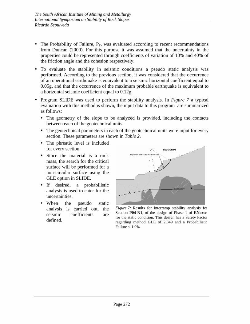
� Program SLIDE was used to perform the stability analysis. In Figure 7 a typical evaluation with this method is shown, the input data to this program are summarized as follows:
� The geometry of the slope to be analyzed is provided, including the contacts between each of the geotechnical units.
� The geotechnical parameters in each of the geotechnical units were input for every section. These parameters are shown in Table 2.
� The phreatic level is included for every section.
� Since the material is a rock mass, the search for the critical surface will be performed for a non-circular surface using the GLE option in SLIDE.
� If desired, a probabilistic analysis is used to cater for the uncertainties.
� When the pseudo static analysis is carried out, the seismic coefficients are defined.
Nivel Freático
Superficie Crítica de Deslizamiento
SECCIÓN P4SECCIÓN P4
Nivel Freático
Superficie Crítica de Deslizamiento
SECCIÓN P4SECCIÓN P4
Figure 7: Results for interramp stability analysis forSection P04-N1, of the design of Phase 1 of ENortefor the static condition. This design has a Safety Factorregarding method GLE of 2.849 and a ProbabilisticFailure < 1.0%.
The South African Institute of Mining and Metallurgy International Symposium on Stability of Rock Slopes Ricardo Sepulveda
Page 273
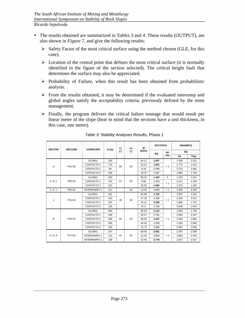
Table 3: Stability Analyses Results, Phase 1
ESTATICO DINAMICO
FS SECTOR SECCIÓN CONDICIÓN H (m)
αG
(°) αIR
(°) W
(Kt/m) FS
PF (%) So Tmp
GLOBAL 330 54.17 1.657 1.548 1.412
CONTACTO 1 176 22.23 1.901 1.772 1.613
CONTACTO 2 86 8.16 2.908 2.732 2.492 A P01-N1
CONTACTO 3 195
50 50
19.70 1.997
< 1
1.882 1.745
GLOBAL 330 69.32 1.424 4 1.323 1.201
CONTACTO 1 120 8.90 2.433 2.317 2.136 C, K, L P03-N1
CONTACTO 2 210
51 50
28.45 1.693 < 1
1.579 1.439
C, K, L P04-N1 INTERRAMPA 1 111 50 14.53 2.849 < 1 2.656 2.420
GLOBAL 292 56.99 1.720 1.597 1.453
CONTACTO 1 142 17.78 2.366 2.206 2.012
CONTACTO 2 187 24.12 2.028 1.886 1.715 J P15-N1
CONTACTO 3 135
49 50
9.11 2.789
< 1
2.648 2.442
GLOBAL 364 90.34 2.112 1.953 1.756
CONTACTO 1 188 30.57 2.781 2.583 2.337
CONTACTO 2 308 58.94 2.207 2.055 1.865
CONTACTO 3 285 44.26 2.408 2.266 2.083
B P16-N1
CONTACTO 4 165
50 50
15.73 2.968
< 1
2.801 2.595
GLOBAL 247 66.09 2.501 2.297 2.038
INTERRAMPA 1 110 12.53 2.840 2.663 2.439 C, D, K P17-N1
INTERRAMPA 2 138
41 50
22.45 2.778
< 1
2.672 2.517
� The results obtained are summarized in Tables 3 and 4. These results (OUTPUT), are also shown in Figure 7, and give the following results:
� Safety Factor of the most critical surface using the method chosen (GLE, for this case).
� Location of the central point that defines the most critical surface (it is normally identified in the figure of the section selected). The critical height fault that determines the surface may also be appreciated.
� Probability of Failure, when this result has been obtained from probabilistic analysis.
� From the results obtained, it may be determined if the evaluated interramp and global angles satisfy the acceptability criteria, previously defined by the mine management.
� Finally, the program delivers the critical failure tonnage that would result per linear metre of the slope (bear in mind that the sections have a unit thickness, in this case, one metre).
The South African Institute of Mining and Metallurgy International Symposium on Stability of Rock Slopes Ricardo Sepulveda
Page 274
EVALUATION OF THE RESULTS
Where an eventual instability would not involve significant consequences and perhaps a relatively superficial slide would take place, the designs carried out can be considered valid.
Criteria for acceptability should consider the following:
• In static conditions, the slopes must be stable enough, and with a probability of failure low enough to allow safe operation.
• In a seismic operational condition, or alternatively in a moderate magnitude seis-mic event, but with a relatively high probability of occurrence during the opera-tional life of the slopes, which is the case of the operational earthquake, the slopes must be stable, with a probability of failure from medium to low.
• In an extreme seismic condition, that is, in the case of a very violent seismic event or with earthquake characteristics, but with a low probability of occurrence during the operational life of the slopes, which is the case of the maximum probable earthquake, the slopes must not reach the condition of limit equilibrium.
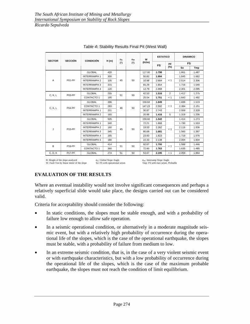
Table 4: Stability Results Final Pit (West Wall)
ESTATICO DINAMICO
FS SECTOR SECCIÓN CONDICIÓN H (m)
αG
(°) αIR
(°) W
(Kt/m) FS PF
(%) So Tmp
GLOBAL 420 117.00 1.798 1.661 1.487
INTERRAMPA 1 300 50.82 1.994 1.845 1.662
INTERRAMPA 2 105 10.98 2.684 2.514 2.306
INTERRAMPA 3 315 65.29 1.854 1.716 1.540
A P01-PF
INTERRAMPA 4 120
45 50
12.79 2.468
< 1
2.301 2.095
GLOBAL 255 42.53 1.516 2 1.412 1.275 C, K, L P03-PF
CONTACTO 1 195 51 50
25.04 1.751 < 1 1.643 1.492
GLOBAL 396 159.84 1.849 1.699 1.519
CONTACTO 1 283 147.23 2.592 2.384 2.151
INTERRAMPA 1 201 30.87 2.743
< 1
2.559 2.328 C, K, L P04-PF
INTERRAMPA 2 165
46 50
20.98 1.416 5 1.319 1.206
GLOBAL 505 159.60 1.542 1.414 1.273
INTERRAMPA 1 340 72.21 1.868 1.730 1.553
INTERRAMPA 2 160 19.53 2.262 2.116 1.936
INTERRAMPA 3 345 80.69 1.681 1.560 1.397
INTERRAMPA 4 165 23.83 1.823 1.719 1.576
J P15-PF
INTERRAMPA 5 180
45 50
22.33 2.138
< 1
2.004 1.834
GLOBAL 414 92.67 1.700 1.588 1.446 B P16-PF
CONTACTO 1 360 51 50
72.60 1.763 < 1
1.635 1.485
C, D, K P17-PF GLOBAL 274 51 50 53.67 2.195 < 1 2.059 1.864 H: Height of the slope analyzed αG: Global Slope Angle αIR: Interramp Slope Angle W: Fault Ton by linear meter of the slope So: FS with operational seism Tmp: FS with max seism. Probable
The South African Institute of Mining and Metallurgy International Symposium on Stability of Rock Slopes Ricardo Sepulveda
Page 275
E-1
7500
E-1
8000
E-1
8500
E-1
9000
E-1
9500
E-2
0000
N-113000
N-113500
N-114000
N-114500
N-115000
RAJO ESCONDIDA NORTE
RECOMENDACIÓN
ÁNGULOS INTERRAMPA
PIT FINAL
SECCIÓN P4FSGLE = 1.42PF = 5 %αIR = 50°
N
SECCIÓN P1FSGLE = 1.80PF = < 1 %αIR = 50°
SECCIÓN P17FSGLE = 2.20PF = < 1 %αIR = 50°
SECCIÓN P16FSGLE = 1.70PF = < 1 %αIR = 50°
SECCIÓN P3FSGLE = 1.52PF = 2 %αIR = 50°
SECCIÓN P15FSGLE = 1.54PF = < 1 %αIR = 50°
ααIRIR = 50°= 50°
E-1
7500
E-1
8000
E-1
8500
E-1
9000
E-1
9500
E-2
0000
N-113000
N-113500
N-114000
N-114500
N-115000
RAJO ESCONDIDA NORTE
RECOMENDACIÓN
ÁNGULOS INTERRAMPA
PIT FINAL
SECCIÓN P4FSGLE = 1.42PF = 5 %αIR = 50°
N
SECCIÓN P1FSGLE = 1.80PF = < 1 %αIR = 50°
SECCIÓN P17FSGLE = 2.20PF = < 1 %αIR = 50°
SECCIÓN P16FSGLE = 1.70PF = < 1 %αIR = 50°
SECCIÓN P3FSGLE = 1.52PF = 2 %αIR = 50°
SECCIÓN P15FSGLE = 1.54PF = < 1 %αIR = 50°
ααIRIR = 50°= 50°
Figure 9: The hatching zone shows the interramp angle rec-ommended (optimized), for ENorte, for the west Wall. The rest of the walls keep the angles recommended in the feasibility study.
RAJO ESCONDIDA
NORTE
ÁNGULOS
INTERRAMPA
RECOMENDADOS
FASE I
SECCIÓN P4FSGLE = 2.85PF = < 1 %αIR = 50°
NSECCIÓN P1FSGLE = 1.66PF = < 1 %αIR = 50°
SECCIÓN P17FSGLE = 2.50PF = < 1 %αIR = 50°
SECCIÓN P16FSGLE = 2.11PF = < 1 %αIR = 50°
SECCIÓN P3FSGLE = 1.42PF = 4 %αIR = 50°
SECCIÓN P15FSGLE = 1.72PF = < 1 %αIR = 50°
αIR = 50°
αIR = 45°
αIR = 49°
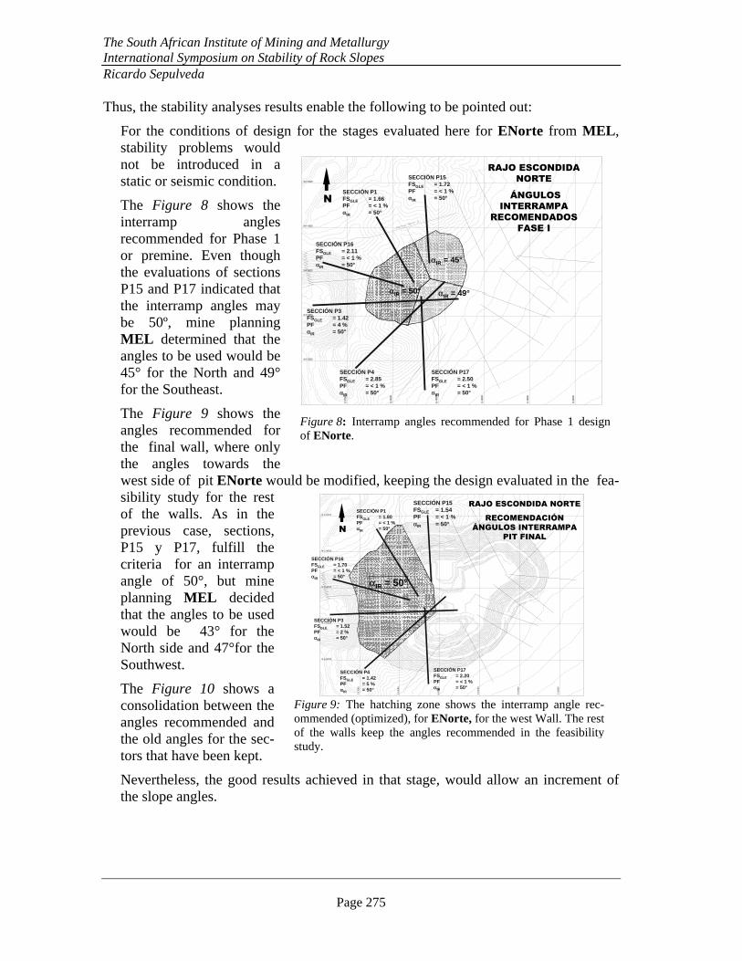
Figure 8: Interramp angles recommended for Phase 1 design of ENorte.
Thus, the stability analyses results enable the following to be pointed out:
For the conditions of design for the stages evaluated here for ENorte from MEL, stability problems would not be introduced in a static or seismic condition.
The Figure 8 shows the interramp angles recommended for Phase 1 or premine. Even though the evaluations of sections P15 and P17 indicated that the interramp angles may be 50º, mine planning MEL determined that the angles to be used would be 45° for the North and 49° for the Southeast.
The Figure 9 shows the angles recommended for the final wall, where only the angles towards the west side of pit ENorte would be modified, keeping the design evaluated in the fea-sibility study for the rest of the walls. As in the previous case, sections, P15 y P17, fulfill the criteria for an interramp angle of 50°, but mine planning MEL decided that the angles to be used would be 43° for the North side and 47°for the Southwest.
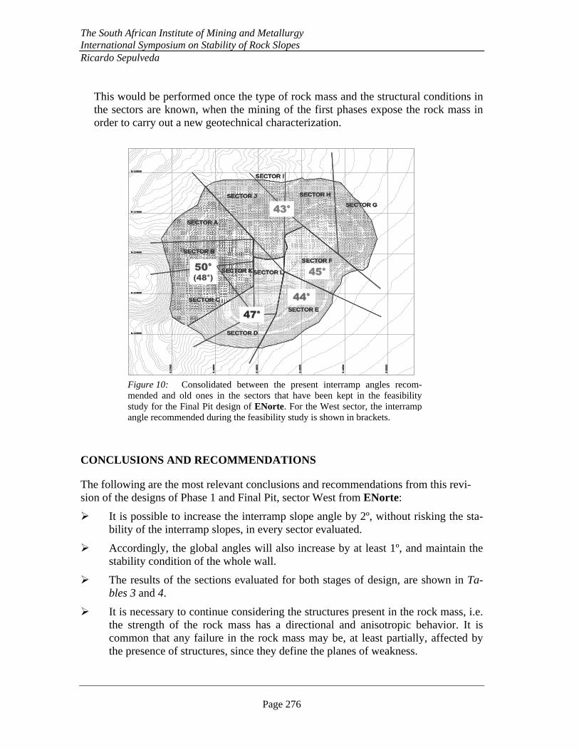
The Figure 10 shows a consolidation between the angles recommended and the old angles for the sec-tors that have been kept.
Nevertheless, the good results achieved in that stage, would allow an increment of the slope angles.
The South African Institute of Mining and Metallurgy International Symposium on Stability of Rock Slopes Ricardo Sepulveda
Page 276
This would be performed once the type of rock mass and the structural conditions in the sectors are known, when the mining of the first phases expose the rock mass in order to carry out a new geotechnical characterization.
CONCLUSIONS AND RECOMMENDATIONS
The following are the most relevant conclusions and recommendations from this revi-sion of the designs of Phase 1 and Final Pit, sector West from ENorte:
� It is possible to increase the interramp slope angle by 2º, without risking the sta-bility of the interramp slopes, in every sector evaluated.
� Accordingly, the global angles will also increase by at least 1º, and maintain the stability condition of the whole wall.
� The results of the sections evaluated for both stages of design, are shown in Ta-bles 3 and 4.
� It is necessary to continue considering the structures present in the rock mass, i.e. the strength of the rock mass has a directional and anisotropic behavior. It is common that any failure in the rock mass may be, at least partially, affected by the presence of structures, since they define the planes of weakness.
E-1
7500
E-1
8000
E-1
8500
E-1
9000
E-1
9500
E-2
0000
N-113000
N-113500
N-114000
N-114500
N-115000
SECTOR D
SECTOR C
SECTOR B
SECTOR A
SECTOR J
SECTOR I
SECTOR E
SECTOR H
SECTOR F
SECTOR G
SECTOR LSECTOR K50°50°
(48°)
43°43°
45°45°
44°44°
47°47°
E-1
7500
E-1
8000
E-1
8500
E-1
9000
E-1
9500
E-2
0000
N-113000
N-113500
N-114000
N-114500
N-115000
SECTOR D
SECTOR C
SECTOR B
SECTOR A
SECTOR J
SECTOR I
SECTOR E
SECTOR H
SECTOR F
SECTOR G
SECTOR LSECTOR K50°50°
(48°)
43°43°
45°45°
44°44°
47°47°
E-1
7500
E-1
8000
E-1
8500
E-1
9000
E-1
9500
E-2
0000
N-113000
N-113500
N-114000
N-114500
N-115000
SECTOR D
SECTOR C
SECTOR B
SECTOR A
SECTOR J
SECTOR I
SECTOR E
SECTOR H
SECTOR F
SECTOR G
SECTOR LSECTOR K50°50°
(48°)
43°43°
45°45°
44°44°
47°47°
Figure 10: Consolidated between the present interramp angles recom-mended and old ones in the sectors that have been kept in the feasibility study for the Final Pit design of ENorte. For the West sector, the interramp angle recommended during the feasibility study is shown in brackets.
The South African Institute of Mining and Metallurgy International Symposium on Stability of Rock Slopes Ricardo Sepulveda
Page 277
� Maintain permanent visual observational control on the behaviour of the slopes, as well as a monitoring and implementation plan. This enables circumstances of instability to be detected immediately.
� Maintain a tight control of the program.
� As a result of the geotechnical evaluations, all the present designs, for every stage evaluated, satisfy the acceptability criteria described. They are stable enough in static conditions, as well as in seismic conditions. Figures 8, 9 and 10 summarize these results.
REFERENCES
[1] Araya R. (1990): Sismicidad y Riesgo Sísmico, en Levantamiento Catastral de los Tranques de Relaves en Chile, Etapa C: Regiones II y III, Tramo 1. Technical Report, Ingeniería & Geotecnia Ltda.
[2] Duncan, J. M. (2000): Factors of Safety and Reliability in Geotechnical Engineer-ing, J. Geotechnical and Geoenvironmental Eng., ASCE, Vol. 126, Nº 4.
[3] Harr, M. (1987): Reliability-Based Design in Civil Engineering, Dover: New York.
[4] Hoek, E. & Bray, J. (1981): Rock Slope Engineering, 3rd ed., IMM, London.
[5] Karzulovic, A., Aguirre, A. & Araya, R. (1989): Definición del Sismo de Opera-ción y del Terremoto Máximo Probable para el Análisis de Estabilidad Sísmica de Depósitos de Relaves. Anales VI Simposium de Ingeniería de Minas, Universidad de Santiago de Chile.
[6] Minera Escondida Limitada (2003): Feasibility Study Escondida Norte.
[7] Rocscience (2003): Slide 5.0: 2D Limit Equilibrium Slope Stability for Soil and Rock Slopes, Rocscience, Geomechanics Software & Research.
[8] Sepúlveda, R. & Mena, C. (2003): Optimización Ángulos de Taludes Escondida Norte, Estudio N° ML-CG-2003-01, Final Report, A. Karzulovic & Asoc. Ltda.
[9] Sepulveda, R & Mena, C. (2003): Evaluación Geotécnica Explotación Simultánea Rajos Zaldívar y Escondida Norte (Transición CMZ- MEL), Estudio N° CMZ 2003-05, A. Karzulovic & Asoc. Ltda.

The South African Institute of Mining and Metallurgy International Symposium on Stability of Rock Slopes Ricardo Sepulveda
Page 278