Embed Size (px)
Citation preview

1
We’re proud to be part of
SITE PRACTICE• PAS 70:2003HD clay bricks Guide to appearanceand site measured dimensions and tolerance.
2
SITE PRACTICE
• PAS 70:2003
HD clay bricks Guide to appearance and site measured dimensions and tolerance.Publicly Available Specification 70 (PAS) provides authoritive guidance, whilst removing reference to contractual arrangements and retaining a sample and reference panel approach to acceptability. The PAS gives a simple test to resolve site disputes without the recourse to long jaw callipers and off site measurement. The following groups contributed to the document.
Brick Development Association Ltd.
Lucideon Ltd (formally Ceram)
Kingston University
National Building Specification
National House Building Council
Office of the Deputy Prime Minister
REFERENCE PANEL
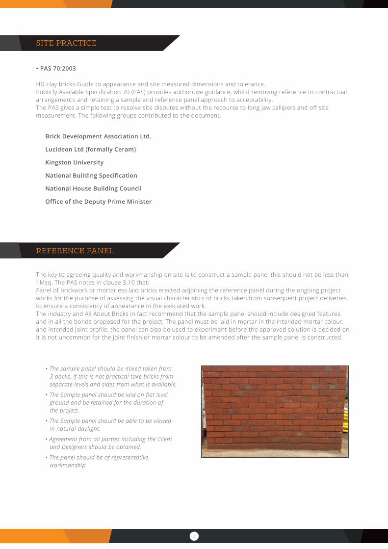
The key to agreeing quality and workmanship on site is to construct a sample panel this should not be less than 1Msq. The PAS notes in clause 3.10 that:Panel of brickwork or mortarless laid bricks erected adjoining the reference panel during the ongoing project works for the purpose of assessing the visual characteristics of bricks taken from subsequent project deliveries, to ensure a consistency of appearance in the executed work.The industry and All About Bricks in fact recommend that the sample panel should include designed features and in all the bonds proposed for the project. The panel must be laid in mortar in the intended mortar colour, and intended joint profile, the panel can also be used to experiment before the approved solution is decided on. It is not uncommon for the joint finish or mortar colour to be amended after the sample panel is constructed.
• The sample panel should be mixed taken from 3 packs. If this is not practical take bricks from separate levels and sides from what is available.
• The Sample panel should be laid on flat level ground and be retained for the duration of the project.
• The Sample panel should be able to be viewed in natural daylight.
• Agreement from all parties including the Client and Designers should be obtained.
• The panel should be of representative workmanship.
3
SAMPLE PANEL
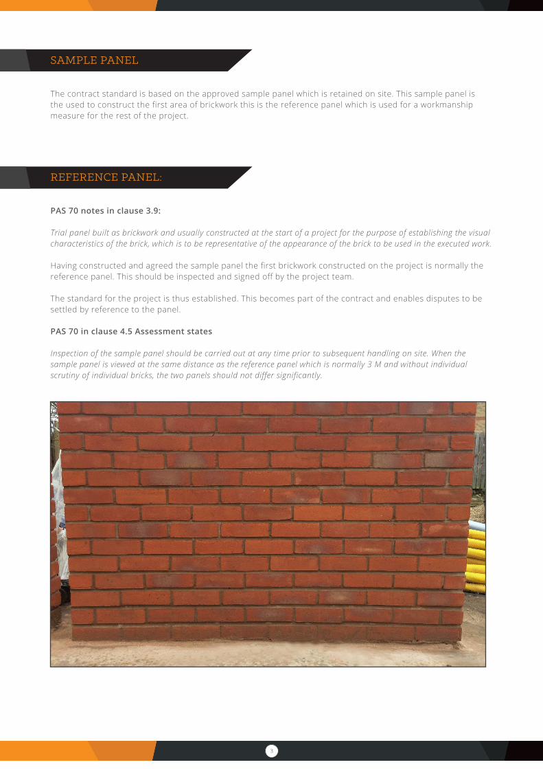
The contract standard is based on the approved sample panel which is retained on site. This sample panel is the used to construct the first area of brickwork this is the reference panel which is used for a workmanship measure for the rest of the project.
REFERENCE PANEL:
PAS 70 notes in clause 3.9:
Trial panel built as brickwork and usually constructed at the start of a project for the purpose of establishing the visual characteristics of the brick, which is to be representative of the appearance of the brick to be used in the executed work.
Having constructed and agreed the sample panel the first brickwork constructed on the project is normally the reference panel. This should be inspected and signed off by the project team.
The standard for the project is thus established. This becomes part of the contract and enables disputes to be settled by reference to the panel.
PAS 70 in clause 4.5 Assessment states
Inspection of the sample panel should be carried out at any time prior to subsequent handling on site. When the sample panel is viewed at the same distance as the reference panel which is normally 3 M and without individual scrutiny of individual bricks, the two panels should not differ significantly.
4
REFERENCE PANEL
Dimension and tolerances:BS EN 771-1 has a more complex method of determining dimensions which are carried out at a test centre. Based on the following criteria using long jawed callipers. This is normally impractical for site work so PAS 70 has a more acceptable practically based site test to swiftly confirm the dimensions of clay bricks. The procedure is listed below.
Procedure A - Tolerances for mean dimensions (T1 T2 or Tm)
• Use a retractable steel rule conforming to BS 4035.
• Sample ten clay bricks in accordance with BS EN 771-1 unless otherwise agreed.
• Remove any superfluous material stuck to the brick.
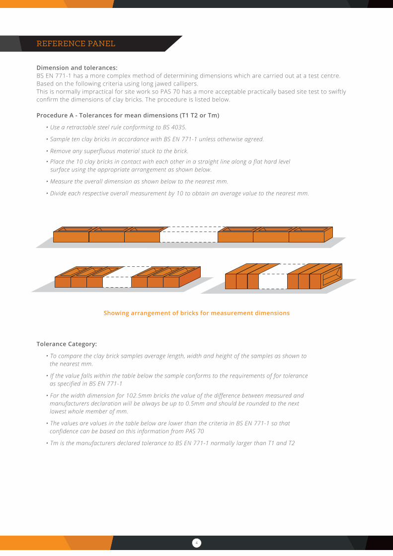
• Place the 10 clay bricks in contact with each other in a straight line along a flat hard level surface using the appropriate arrangement as shown below.
• Measure the overall dimension as shown below to the nearest mm.
• Divide each respective overall measurement by 10 to obtain an average value to the nearest mm.
Tolerance Category:
• To compare the clay brick samples average length, width and height of the samples as shown to the nearest mm.
• If the value falls within the table below the sample conforms to the requirements of for tolerance as specified in BS EN 771-1
• For the width dimension for 102.5mm bricks the value of the difference between measured and manufacturers declaration will be always be up to 0.5mm and should be rounded to the next lowest whole member of mm.
• The values are values in the table below are lower than the criteria in BS EN 771-1 so that confidence can be based on this information from PAS 70
• Tm is the manufacturers declared tolerance to BS EN 771-1 normally larger than T1 and T2
Showing arrangement of bricks for measurement dimensions
5
Procedure B Tolerance category for range (R1, R2. And Rm)
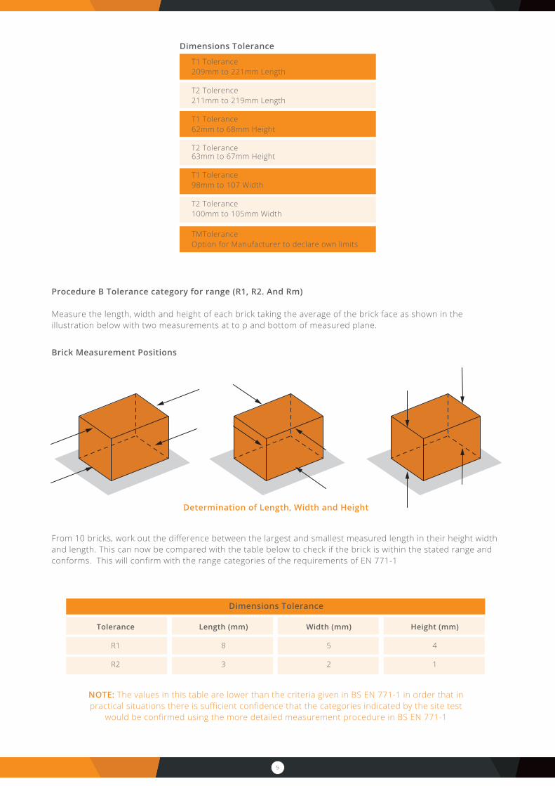
Measure the length, width and height of each brick taking the average of the brick face as shown in the illustration below with two measurements at to p and bottom of measured plane.
From 10 bricks, work out the difference between the largest and smallest measured length in their height width and length. This can now be compared with the table below to check if the brick is within the stated range and conforms. This will confirm with the range categories of the requirements of EN 771-1
Dimensions Tolerance
T1 Tolerance209mm to 221mm Length
T2 Tolerence211mm to 219mm Length
T1 Tolerance62mm to 68mm Height
T2 Tolerance63mm to 67mm Height
T1 Tolerance98mm to 107 Width
T2 Tolerance100mm to 105mm Width TMToleranceOption for Manufacturer to declare own limits
Determination of Length, Width and Height
Brick Measurement Positions
Dimensions Tolerance
Tolerance
R1
R2
Length (mm)
8
3
Width (mm)
5
2
Height (mm)
4
1
NOTE: The values in this table are lower than the criteria given in BS EN 771-1 in order that in practical situations there is sufficient confidence that the categories indicated by the site test
would be confirmed using the more detailed measurement procedure in BS EN 771-1

6
MORTAR
Mortars conform to the requirements of BS EN 998-2 if they are factory made, but if they are site batched they are defined by a design document, BS1996-1-1, Eurocode 6. These standards cover a number of properties, including strength. The published document is PD 6678. There are two ways to specify mortar.
Designed Mortars: composition and manufacturing method is selected by the producer tochoose specified properties. They’re classified by their compressive strength.
Prescribed Mortars: Are made in pre-determined proportions, the properties of which areassumed from the stated proportions of the constituents and are classified by designations. Itis difficult to state categorically the proportions can be equated to the strength intimated in thetable below but it is sufficient as a guide.
The wet mortar properties, for example the water: cement ratio, should be determined by the bricklayer/labourer, who will need to adjust the mix to the correct wetness for laying the particular units in the particular weather conditions with the particular brick.
A cold winter day with engineering bricks will require a drier mix than a hot summer, perhaps in full sunlight, with absorptive stock bricks. Both extremes have the potential to produce good masonry, but the final wetness, and thus the workability, of the mortar must be left to the experience of the bricklayer.
Many designers prefer natural mortars with the colour in the mortar being altered by the selection in sand. Coloured mortars matching the brick can be specified as lower quality workmanship can be disguised by the wall being perceived as a whole without individual bricks standing out. Pigments are frequently used in mortars and often based on metallic oxides, generally of iron. They are chemically stable and will not fade. Visual colour loss may occur if the surface of the joint becomes eroded due to the effects of weathering. Pigments based on carbon are unsuitable for external use as they will fade, although they are low cost. Coloured mortar has the effect of making the wall more homogeneous and can be a panacea in complex bonding even if the jointing is below the desired standard. Mortar can be tinted effectively. Oxides can be effectively used to cover up both inconsistencies in the mortar and to disguise water saturation and damage.
BRICK TINTING
Brick tinting enables the colour of a brick to be altered even substantially, it does require skill and experience to match and repair existing or new build brickwork to suit its surroundings. Bricks can be tinted; to exactly match the original this can be used for both new work which has been water stained or come from different batches. It is even possible that the colour of the brickwork is not as expected and this can be altered. Inconsistencies in colour from various batches of new bricks can lead to a patchy appearance particularly in new-build projects. Similarly, new build developments often specify bricks that are unsympathetic and do not complement the surrounding environment. The brick tinting service needs to be both experienced and prepared to experiment with a small area before proceeding a larger area.
NOTE: Lime mortars used prior to the late 19th Century are becoming popular again and if considered should be specified with the assistance of a specialist mortar supplier
BS EN 998-2 2013 Mortar Mix table
DesignedMortars
CompressiveStrength
Class
MortarDesignation
Prescribed mortars (proportions of material by volume)
Environmentalusage conditon
Portland Cement or Sulfate resisting Portland cement and lime, with or
without airentering additive
Masonary cementcontaining Portland
cement and lime in approx 1:1 ratio, and air entraining
additive
Masonary cementcontaining Portland cement (min 75%)
and inorganic materials other
than lime, and air entraining additive
Portland cement or Sulfate resisting Portland cement
and an air entraining additive
M12
M6
M4
M2
(i)
(ii)
(iii)
(iv)
1:0 to 1/4:3
1:1/2:4 to 4 1/2
1:1:5 to 6
1:2:8 to 9
-
1:3
1:3 1/2 to 4
1:4 1/2
-
1:2 1/2 to 3
1:4 to 5
1:5 1/2 to 6 1/2
1:3
1:4
1:5 to 6
1:7 to 8
Servere (S)
Servere (S)
Moderate (M)
Passive (P)
7
FREESTANDING WALLS
Freestanding walls are not generally governed by building regulations, they are unregulated. Freestanding walls should never be built with less than a full brick width or 215mm wide if higher than 725mm high. A full brick wall can normally be built up to 1925mm if built in a sheltered location. The foundations must be suitable for the ground and conditions.
Proper design is critical to freestanding walls, because their relative slenderness affects their stability in relation to horizontal forces, particularly wind. In an exposed location even a 215mm wide wall should not be higher than 1075mm.
Piers can be used in freestanding wall design are to strengthen 1/2 brick walls and giving additional strength to full brick walls when required. These all need a designer to specify for the particular requirements of location and conditions.
Freestanding walls require Movement Joints at 6M centres in walls. All walls longer than about 9M require movement joints to cater for expansion. These vertical joints break the wall into discontinuous lengths to prevent cumulative stress that could cause cracking, movement or instability.
Movement joints for free standing walls should be at an absolute Maximum be located no further than 4m from a corner. Short returns in brickwork can be vulnerable, if they interrupt long straight runs they can concentrate stress and cause cracking. Such returns should be treated as corners even if they are only a half brick offset.Movement joints should be continuous for the full height of the wall, including any coping or capping. They should be 15mm wide and filled with a soft, compressible polyethylene or polyurethane cellular foam to keep stones or mortar out and allow the gap to close partially over time. Sealant can give the joint a neat finish – especially in copings or capping – but it must not be pointed with mortar this is sometimes done in error but, may lead to failure.
Maintaining alignment of the wall across a movement joint slip ties can be incorporated, spaced at third points between ground level with a topmost tie four or five courses below the top of the wall. These de-bonded ties should be of stainless steel, shaped at one end to bond with mortar in a bed joint on one side of the movement joint. The other end should be plain and enclosed in a plastic sleeve with a gap at the end at least equal to the width of the movement joint; it is set in the corresponding mortar joint in the adjoining length of wall. The ties allow the movement gap to close, but resist any other movement.
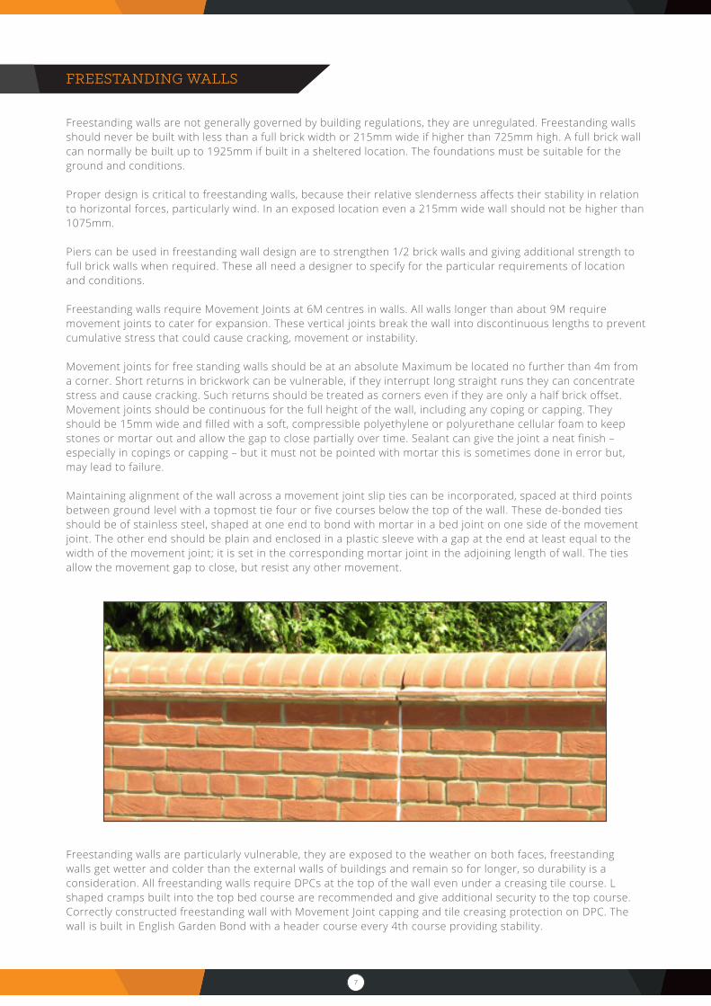
Freestanding walls are particularly vulnerable, they are exposed to the weather on both faces, freestanding walls get wetter and colder than the external walls of buildings and remain so for longer, so durability is a consideration. All freestanding walls require DPCs at the top of the wall even under a creasing tile course. L shaped cramps built into the top bed course are recommended and give additional security to the top course. Correctly constructed freestanding wall with Movement Joint capping and tile creasing protection on DPC. The wall is built in English Garden Bond with a header course every 4th course providing stability.
8
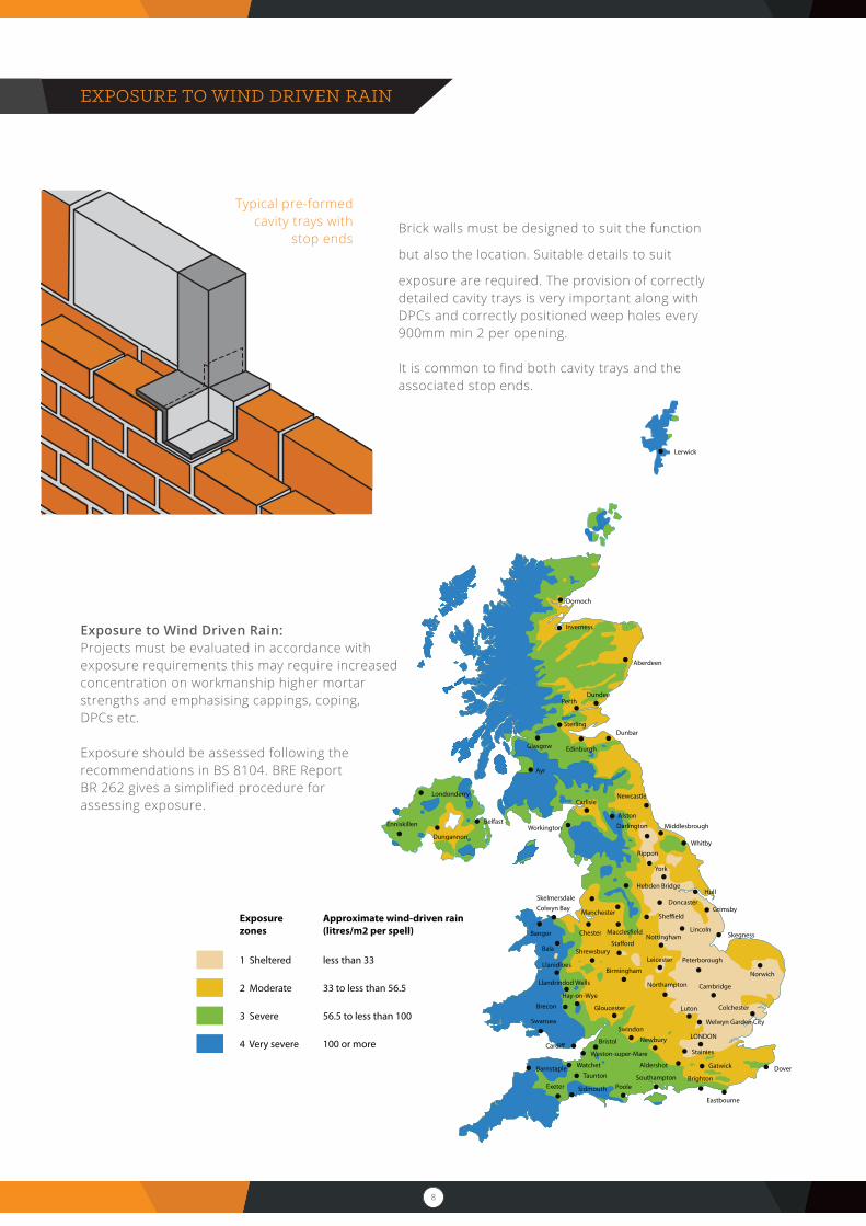
EXPOSURE TO WIND DRIVEN RAIN
Brick walls must be designed to suit the function
but also the location. Suitable details to suit
exposure are required. The provision of correctly detailed cavity trays is very important along with DPCs and correctly positioned weep holes every 900mm min 2 per opening.
It is common to find both cavity trays and the associated stop ends.
Exposure to Wind Driven Rain: Projects must be evaluated in accordance with exposure requirements this may require increased concentration on workmanship higher mortar strengths and emphasising cappings, coping, DPCs etc.
Exposure should be assessed following the recommendations in BS 8104. BRE Report BR 262 gives a simplified procedure for assessing exposure.
Typical pre-formed cavity trays with
stop ends
9
WORK ON SITE
Information and recommendations relating to masonry are contained in PD 6697:2010 chapter 8 work should conform to a good level of basic workmanship and with the information contained in BS 8000-3
MATERIALS, HANDLING AND PREPARATION:
The site should be tidy and clean. Materials should be easily quantified and be assessable for handling. The recommendations and protection should be followed and if the product requires it protected from rain and certainly frost action.
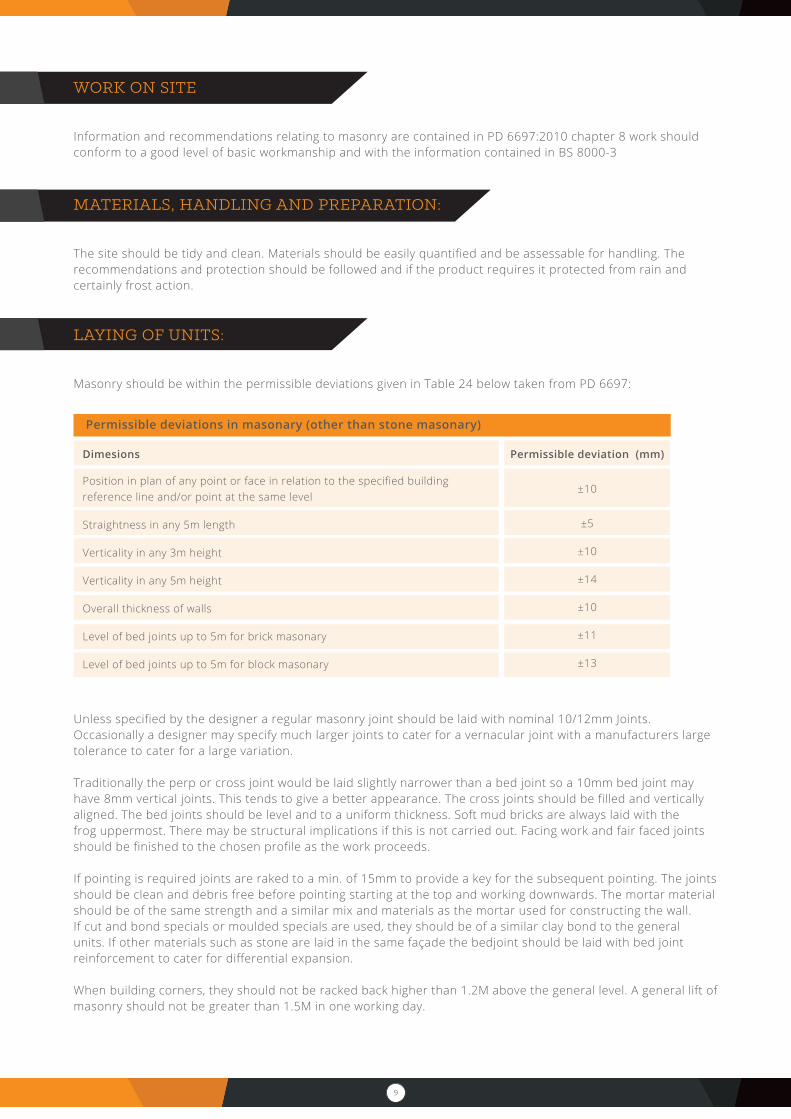
LAYING OF UNITS:
Masonry should be within the permissible deviations given in Table 24 below taken from PD 6697:
Unless specified by the designer a regular masonry joint should be laid with nominal 10/12mm Joints. Occasionally a designer may specify much larger joints to cater for a vernacular joint with a manufacturers large tolerance to cater for a large variation.
Traditionally the perp or cross joint would be laid slightly narrower than a bed joint so a 10mm bed joint may have 8mm vertical joints. This tends to give a better appearance. The cross joints should be filled and vertically aligned. The bed joints should be level and to a uniform thickness. Soft mud bricks are always laid with the frog uppermost. There may be structural implications if this is not carried out. Facing work and fair faced joints should be finished to the chosen profile as the work proceeds.
If pointing is required joints are raked to a min. of 15mm to provide a key for the subsequent pointing. The joints should be clean and debris free before pointing starting at the top and working downwards. The mortar material should be of the same strength and a similar mix and materials as the mortar used for constructing the wall.If cut and bond specials or moulded specials are used, they should be of a similar clay bond to the general units. If other materials such as stone are laid in the same façade the bedjoint should be laid with bed joint reinforcement to cater for differential expansion.
When building corners, they should not be racked back higher than 1.2M above the general level. A general lift of masonry should not be greater than 1.5M in one working day.
Permissible deviations in masonary (other than stone masonary)
Dimesions
Position in plan of any point or face in relation to the specified building reference line and/or point at the same level
Straightness in any 5m length
Verticality in any 3m height
Verticality in any 5m height
Overall thickness of walls
Level of bed joints up to 5m for brick masonary
Level of bed joints up to 5m for block masonary
Permissible deviation (mm)
±10
±5
±10
±14
±10
±11
±13
10
CAPPING AND COPINGS
Cappings and Copings protect the wall beneath they require additional care and should be made of Durable materials F2 and S2 designation bonded often with the use of SS cramps and always laid on a DPC to stop water penetrating through the wall. Movement Joints are always required at max 3M centres. A solder course is not suitable for a top course; this is confirmed in the Severe Exposure Document published by the BDA in 2014.
To be effective the top course needs:
• To laid to a fall to shed water with an overhang with a drip to either side.• The unit must be extremely durable• Laid on a high bond DPC mortared either side of the DPC which is lapped and sealed at junctions.• MJs at 3M centre. With a compressed and worked mortar joint normally minimum M6 mortar.
MORTAR DESIGNATIONS
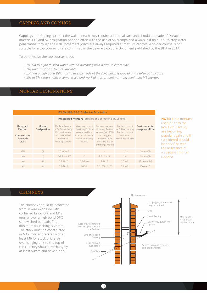
CHIMNEYS
The chimney should be protected from severe exposure with corbelled brickwork and M12 mortar over a high bond DPC sandwiched beneath. The minimum flaunching is 25mm. The stack must be constructed in M12 mortar preferably or at least M6 for stock bricks. An overhanging unit to the top of the chimney should overhang by at least 50mm and have a drip.
NOTE: Lime mortars used prior to the late 19th Century are becoming popular again and if considered should be specified with the assistance of a specialist mortar supplier
BS EN 998-2 2013 Mortar Mix table
DesignedMortars
CompressiveStrength
Class
MortarDesignation
Prescribed mortars (proportions of material by volume)
Environmentalusage conditon
Portland Cement or Sulfate resisting Portland cement and lime, with or
without airentering additive
Masonary cementcontaining Portland
cement and lime in approx 1:1 ratio, and air entraining
additive
Masonary cementcontaining Portland cement (min 75%)
and inorganic materials other
than lime, and air entraining additive
Portland cement or Sulfate resisting Portland cement
and an air entraining additive
M12
M6
M4
M2
(i)
(ii)
(iii)
(iv)
1:0 to 1/4:3
1:1/2:4 to 4 1/2
1:1:5 to 6
1:2:8 to 9
-
1:3
1:3 1/2 to 4
1:4 1/2
-
1:2 1/2 to 3
1:4 to 5
1:5 1/2 to 6 1/2
1:3
1:4
1:5 to 6
1:7 to 8
Servere (S)
Servere (S)
Moderate (M)
Passive (P)
Flu terminal
If coping is jointless DPC may be omitted
Drip
Lead flashing
Lead valley gutter and upstand
Max height= 4.5 x leastwidth of stack
Severe exposure requires and additional tray
Lead tray terminated with an upturn within
the flu liner
Line of stepped flashing
Lead flashingover apron
Roof line
11
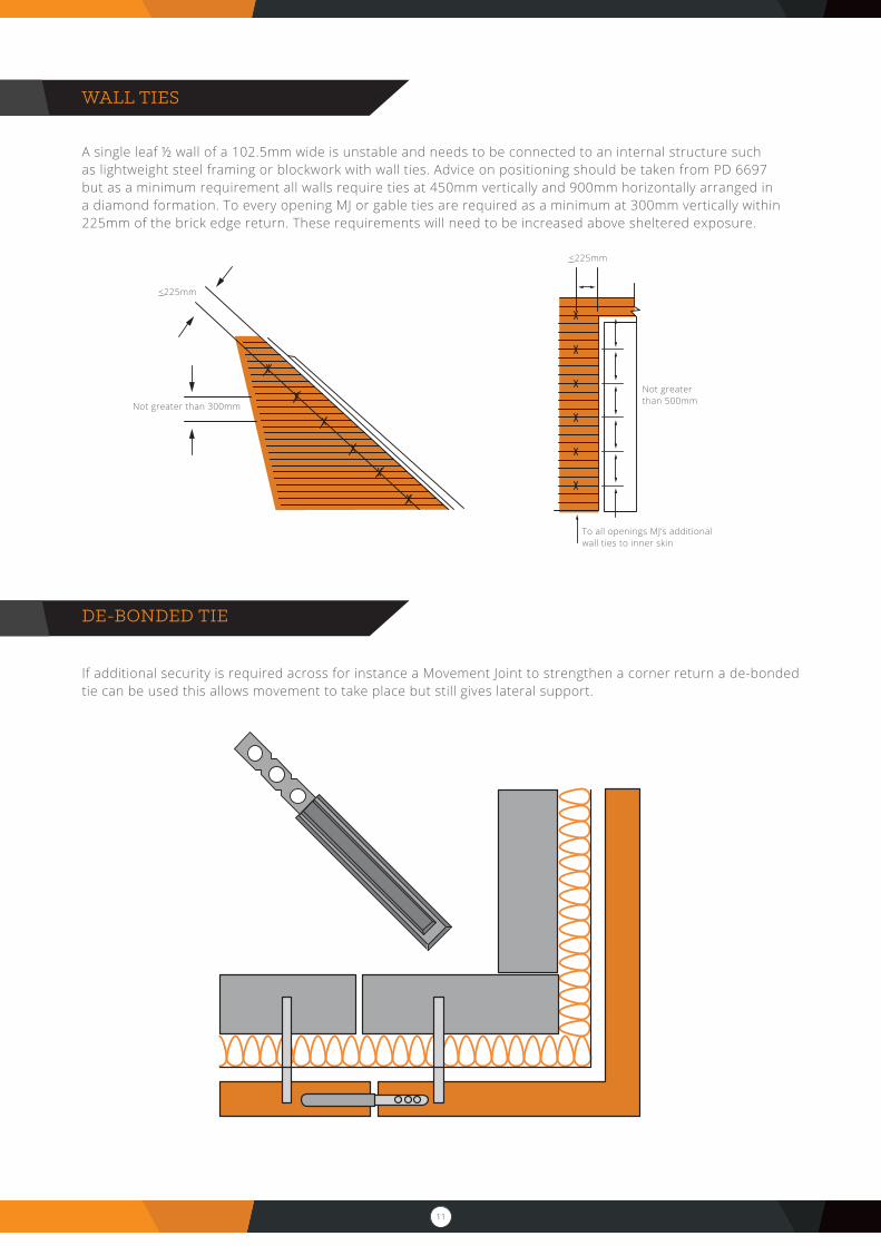
WALL TIES
A single leaf ½ wall of a 102.5mm wide is unstable and needs to be connected to an internal structure such as lightweight steel framing or blockwork with wall ties. Advice on positioning should be taken from PD 6697 but as a minimum requirement all walls require ties at 450mm vertically and 900mm horizontally arranged in a diamond formation. To every opening MJ or gable ties are required as a minimum at 300mm vertically within 225mm of the brick edge return. These requirements will need to be increased above sheltered exposure.
DE-BONDED TIE
If additional security is required across for instance a Movement Joint to strengthen a corner return a de-bonded tie can be used this allows movement to take place but still gives lateral support.
<225mm
Not greater than 300mm
<225mm
Not greater than 500mm
To all openings MJ’s additional wall ties to inner skin
12
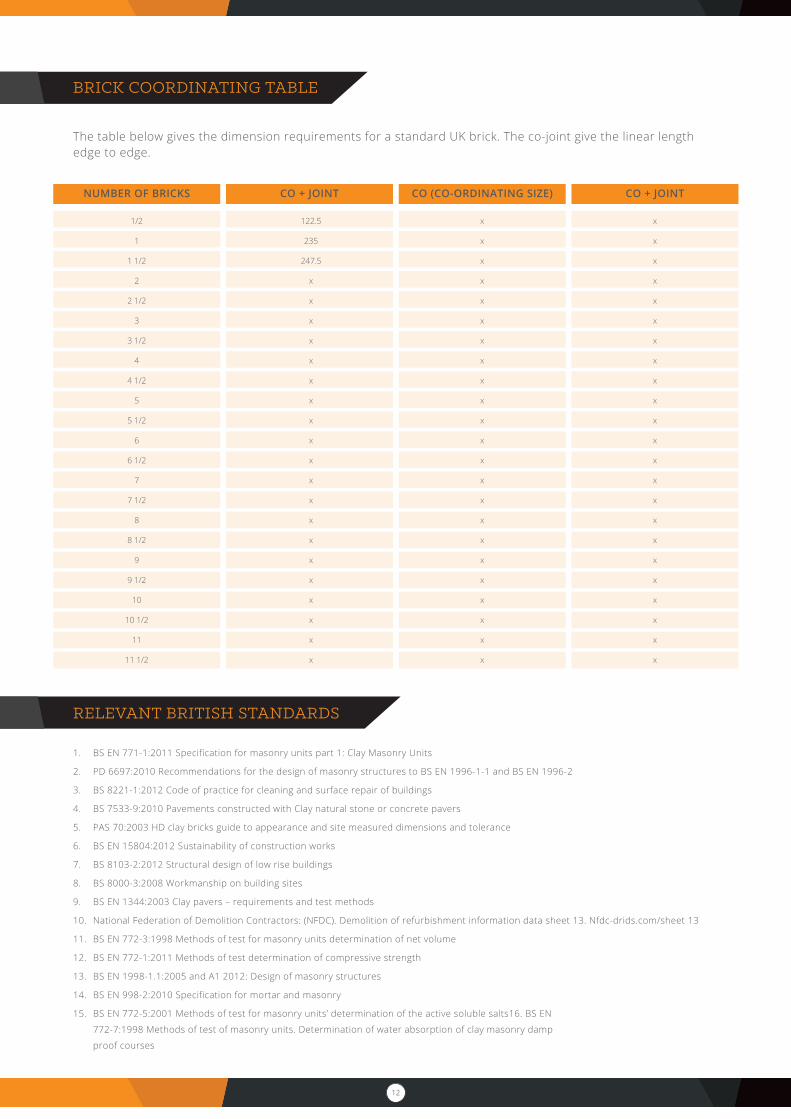
BRICK COORDINATING TABLE
The table below gives the dimension requirements for a standard UK brick. The co-joint give the linear length edge to edge.
RELEVANT BRITISH STANDARDS
1. BS EN 771-1:2011 Specification for masonry units part 1: Clay Masonry Units
2. PD 6697:2010 Recommendations for the design of masonry structures to BS EN 1996-1-1 and BS EN 1996-2
3. BS 8221-1:2012 Code of practice for cleaning and surface repair of buildings
4. BS 7533-9:2010 Pavements constructed with Clay natural stone or concrete pavers
5. PAS 70:2003 HD clay bricks guide to appearance and site measured dimensions and tolerance
6. BS EN 15804:2012 Sustainability of construction works
7. BS 8103-2:2012 Structural design of low rise buildings
8. BS 8000-3:2008 Workmanship on building sites
9. BS EN 1344:2003 Clay pavers – requirements and test methods
10. National Federation of Demolition Contractors: (NFDC). Demolition of refurbishment information data sheet 13. Nfdc-drids.com/sheet 13
11. BS EN 772-3:1998 Methods of test for masonry units determination of net volume
12. BS EN 772-1:2011 Methods of test determination of compressive strength
13. BS EN 1998-1.1:2005 and A1 2012: Design of masonry structures
14. BS EN 998-2:2010 Specification for mortar and masonry
15. BS EN 772-5:2001 Methods of test for masonry units’ determination of the active soluble salts16. BS EN
772-7:1998 Methods of test of masonry units. Determination of water absorption of clay masonry damp
proof courses
CO + JOINT CO (CO-ORDINATING SIZE) CO + JOINTNUMBER OF BRICKS
1/2
1
1 1/2
2
2 1/2
3
3 1/2
4
4 1/2
5
5 1/2
6
6 1/2
7
7 1/2
8
8 1/2
9
9 1/2
10
10 1/2
11
11 1/2
122.5
235
247.5
x
x
x
x
x
x
x
x
x
x
x
x
x
x
x
x
x
x
x
x
x
x
x
x
x
x
x
x
x
x
x
x
x
x
x
x
x
x
x
x
x
x
x
x
x
x
x
x
x
x
x
x
x
x
x
x
x
x
x
x
x
x
x
x
x
x

13
Unit 12, Brunts Business Centre, Samuel Brunts Way, Mansfield, Nottinghamshire. NG18 2AH
T. 0845 2300941
F. 0845 2300942
allaboutbricks.co.uk