Embed Size (px)
Citation preview

W. N I -b K
NWC TP 6098
0 Aircrew Giliding Escape Sse(AGES) Exploratory Development '1
SInvestigation of Aircrew Emergencdygel Escape Ram-Air Inflated,,"
Flexible Wing
byJon T. Matsuo
andManley C. Butler, Jr.
Aerosystem7s Dtpartmeflt
SEPTEMBER 1983 Jr
NAVAL WEAPONS CENTER:CHINA LAKE, CALIFORNIA 93555.
;NWC
Approved for public release; distribu tiof Un~rmlted.
DTICAPR 9IM
B-
BEST AVAILABLE COPY
" . A
FOREWORD
Thsrpotwsprep~ared by the Aerosystems Department of h,.a,
Center, China Lake. Calif. The report covers investigations conducte onasti
air inflated, flexible parcuewusdsge to be used inanazcem#eji i~eq
system. Data were acquired between August 1975 and June 1983 ,under lauthoA
Naval Air Systems Command, AIRTASK A34OOOOO/O66B/5f4l45I 4O 1,61,irrev d
Escape System.
This report was reviewed for technical accuracy by Donald Goodrich'.,
Approved by Udr~h~~
C. V. BRYAN, Il'ad K.A.DICKEA9O0
A erosvstc'fls Depac1itien!23 September 1983
Released for publication by-, k
B. W. HAYS ~~Technical Director.:
NWC Tochnical Publication 6098 t4 ~
Publishcd 1, ........................................ Aerosystems 15epar tment-..,,ý
Colilat ion....................................................... Covet; 0lit ri i g.......................................................
105 xPe
BEST AVAILABLE COPYth~ .r
(UNC•IARSIFIFDfl'EeCUAII'Y CLASSIFICATION OF THIS PAQG (W"On Data EntoredJ)
I PAGE READ INSTRUCTIONSREPORT DOCUMENTATION PBEFORE COMPLETING FORM1. R10P9PORT NUMSEiR 12, GOVT ACCFSSION NO. S. RECIPIENT'S CATALOG NUMBER
NWC TP 6098
4. TITLE (iadSublfite) 5. TYPE OF REPORT & PERIOD COVERED
Aircrew Gliding Escape System (AGES) Exploratory Development Summary report for Augiist 1975 -Investigation of Aircrew Emergency Escape Ram-Air Inflated, June 1983Flexible Wing 6. PERFORMING ORG. REPORT NUMBER
7. AUTHOR(s) S. CONTRACT OR GRANT NUMBER(s)
Jon T. MatsuoManley C. Bulter, Jr.
9. PERFORMING ORGANIZATION NAME AND ADDRESS 10. PROGRAM ELEMENT, PROJECT, TASK
AREA & WORK UNIT NUMBERS
Naval Weapons Center AIRTASK A3400000/066B/China Lake, CA 93555 Sf41451404
I I. CONTROLLING OFFICE N AME AND ADDRESS 12. REPORT DATE
Naval Weapons Center September 1983China Lake, CA 93555 13. NUMBER OF PAGES
3814. MONITORING AGENCY N.•. & ADDRESS(II different from Controlling Office) IS. SECURITY CLASS. (of this report)
UNCLASSIFIED
ISe. DECL ASSI FICATION/DOWNGRADINGSCHEDULE
16. DISTRIBUTION STATEMENT (of this Report)
Approved for public release; distribution unlimited.
17. DISTRIBUTION STATEMENT (of the abetract entered In Block 20, If different from Report)
18. SUPPLEMENTARY NOTES
19. KEY WORDS (Continue on revere. side if necessary aid identify by block number)
Parachutes Ram-air .iitlated. flexiblejecti ll Seat escape system Wing canopy
Aircrew gliding escape system (AGES)CanOpV Conllit mrtl ions >-
20. ABSTRACT (Continue on reverse side if necessary amd Identify by block numbeo) C-LJ
S~.e h'ck of' thrum,
-cJ
I-COLiiJ
S...... 1473 Fr,,rIO• OF I NOV 65 IS OBSOLETE"Il ', IO,. I F .o __-,,__o (IJN('.LASSII:11l))
SECURITY CLASSIFICATION OF THIS PAGE (Woen Del. Nnfered)
(UNCLASSIFIED)SICURItY CLASSItICATION OP THII PACKif (lhl Da01 ui1"oW94)
(U) Aircrew Gliding Escape Svstem (AGES) Exploratory DevelopmenttInvesHtgaIton of Aircrew Emergency Escape Ram-Air Inflated, FlexibleWing, by JonT. Matsuo and Manley C. Butler, Jr. China Lake, Calif.,Naval Weapons Center, September 1983. 38 pages, (NWC TP 6098,publication UNCLASSIFIED.)
(U) The objective of the aircrew gliding escape system (AGES) pro.gram is to investigate the feasibility of incorporating a ram-air inflated,flexible wing parachute canopy into contemporary military aircrewejicction seat escape systems. This rcport dosciibc Llhc research, develop.ment, fabrication, and testing of the AGES ram-air inflated parachutewings. The primary focus of the investigation to date was on high-airspeedtests in order to obtain data on the structural integrity of the parachutewing and reefing system design and perforniance.
(U) Tests were made on 13 configurations over a period of 8 years,including 36 torso dummy drop tests and one cylindrical test vehicle(CTV) test used to evaluate the compatibility of the AGES canopy withthe sealed pack developed for the maximum performance ejection seatprogrim (MPES). These tests provided data on the structural integrity ofthe wing, container design, deployment dynamics, reefing performance,and inflation dynamics. The final configuration was tested at speeds ashigh as 300 knots indicated airspeed at pack opening without structuraldamage.
1'.D
co
(UN(N LASSIF lliI))SECURITY CLASSIFICATION or TIIIS PAGE(Whon Data Entered)
NWC TP 6098
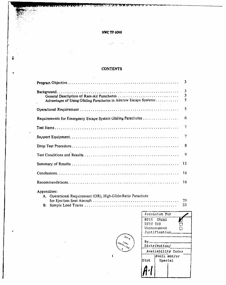
CONTENTS
Program Objective ................................................... 3
Background .......................................................... 3General Description of Ram-Air Parachutes ............................. 3Advantages of Using Gliding Parachutes in Aircrew Escape Systems ........... 5
O perational Requirem ent ............................................... 5
Requirements for Emergency Escape System Gliding Parachutes ................. 6
T est Item s ...................... ................................... .. 7
Support Equipm ent .................................................... 7
Drop Test Procedure ............................................... 8
Test Conditions and Results ............................................. 9
Sum m ary of Results ................................................... 15
C onclusions .......................................................... 16
R ecom m endations ..................................................... 16
Appendixes:A. Operational Requirement (OR), High-Glide-Ratio Parachute
for Ejection Seat Aircraft ......................................... 29B. Sam ple Load Traces ............................................ 33
Accecssion For
NTIS GRA&I
DTIC TABUnannouncedJustification
Distribution/
Availability CodesAvail and/or
Dist Special
NViC "'P 609t;
PROGRAM OBJECTIVE
'he objective of the aircrew gliding escape system (AG-S) program is to invest-igate the feasibility of incorporating a ram-air inflated flexible wing parachutc canopy
into contemporary military aircrew ejection seat escape systems with resulting benefitsin these areas:
1. Lower rate of descent (in the "hands-off" mode)-. 2. Lower opening forces at high speed while reducing the opening times at low"' ~speeds
"3. Enhanced maneuverability and evasion capabilities
BACKGROUND
Current emergency aircrew escape parachute systems have demonstrated reliableoperation but still lack the capability to permit the crewman to maneuver to a favor-able landing site. The 28-foot-diameter, flat, circular canopy (2QC) is the mostcommon parachute used in Navy ejection seat aircraft and has recently been fitted withthe four-line release modification (which was not available for use in Southeast Asiaoperations during the Vietnam War). The four-line release system greatly reduces theoscillation of the canopy and provides for a very limited maneuverability. iowever,significant problems include high rate of descent; high opening shock at high speeds, andslow opening at low speeds, which requires the use of a spreader gun, a droguegun/deployment rocket, or a combination of both with some systems. The weight ofthese devices causes the canopy to sink, which in addition to the long suspension linesaggravates the problem of parachute entanglement in water landings.
The only other canopy in current use in Navy ejection seats is the GQ Aeroconicalparachute installed in the Martin-Baker seat used in the F-lE aircraft. The
Aeroconical is a 5.2-meter, round parachute with mesh-covered vents in the rear of thecanopy that give the parachute forward speed. The combination of a high rate of des-cent and a horizontal velocity component leads to a high total impact velocity. Thisproblem has given rise to a program to replace the Aeroconical with the AutomaticInflation Modulation (AIM) parachute manufactured by Irvin Industries Canada.
GENERAL DESCRIPTION OF RAM-AM PARACHUTES
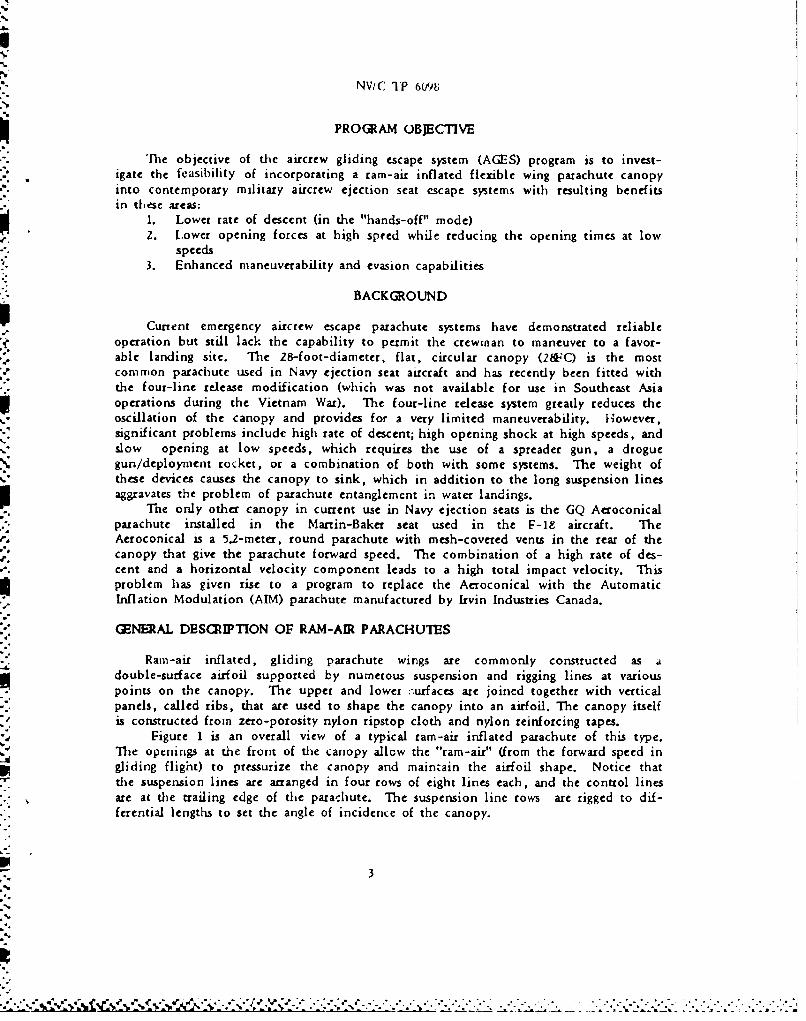
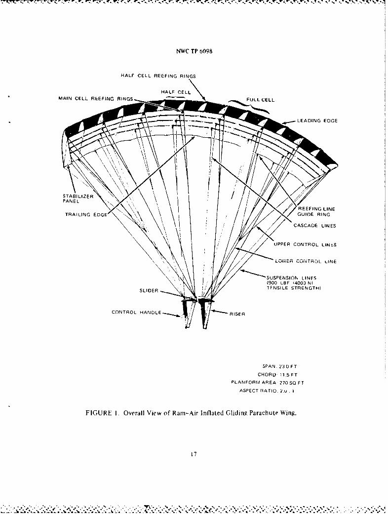
Ram-air inflated, gliding parachute wings are commonly constructed as adouble-surface airfoil supported by numerous suspension and rigging lines at variouspoints on the canopy. The upper and lower :;urfaces are joined together with verticalpanels, called ribs, that are used to shape the canopy into an airfoil. The canopy itselfis constructed from zero-porosity nylon ripstop cloth and nylon reinforcing tapes.
Figure 1 is an overall view of a typical ram-air inflated parachute of this type.The openings at the front of the canopy allow the "ram-air" (from the forward speed ingliding flight) to pressurize the canopy and maintain the airfoil shape. Notice thatthe suspension lines are arranged in four rows of eight lines each, and the control linesare at the trailing edge of the parachute. The suspension line rows are rigged to dif-ferential lengths to set the angle of incidence of the canopy.
3
-'. " - " " " ,. " , ," r -- " , . ," . .- , - - -. - . . . . . . .. - . . - .. . - . .. - . . . . - . . . . . . . . .
NWC TP 6098
Opening Characteristics and Rcefin2 Systems
The opening of ram-air inflated gliding wing parachutes is so rapid that some type
of reefing system must be used to prevent structural damage to the parachute and injuryto the jumper. Over tie past 15 yeas, many different types of reefing devices weretried and abandoned; however, two basic types of reefing devices proved suitable forintentional sport parachute jumping and are in wide use today.
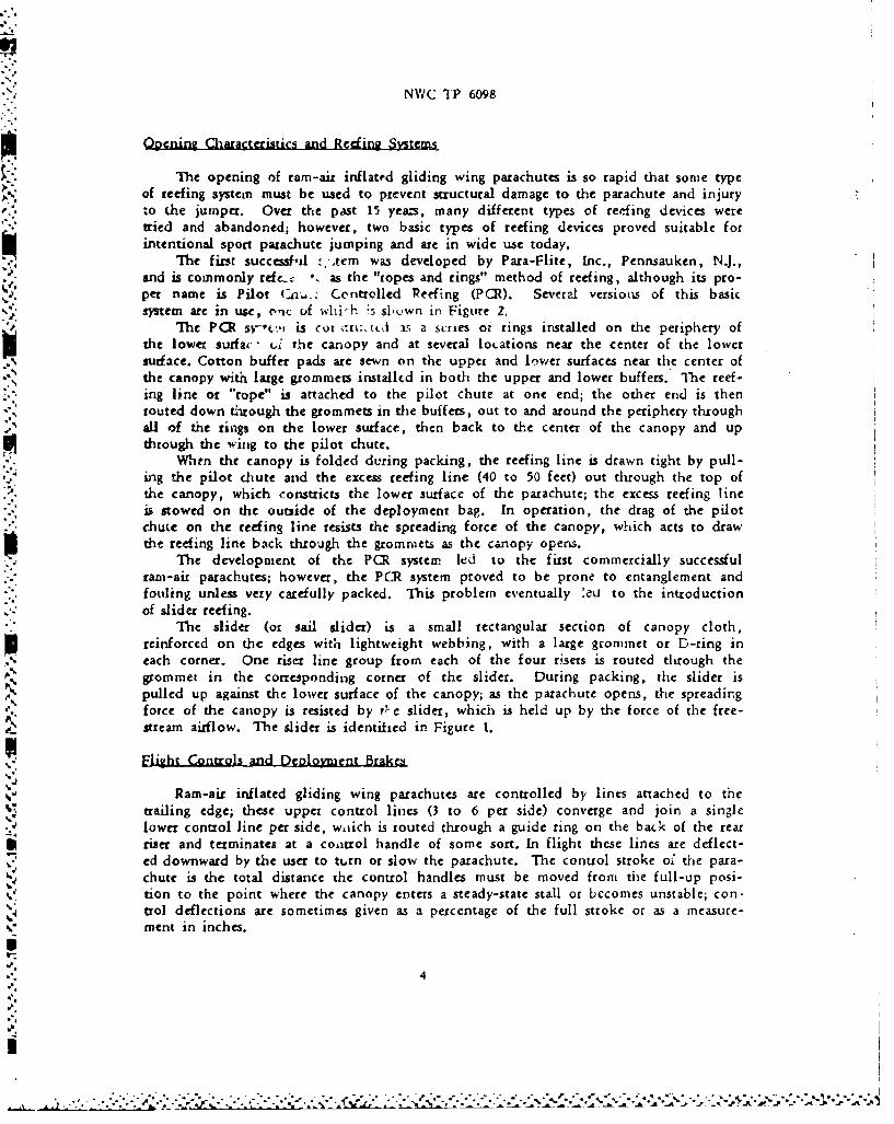
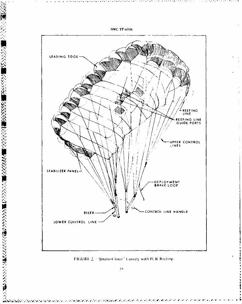
The first successful -;trcm was developed by Para-Flite, Inc., Pennsauken, NJ.,and is commonly refc-c -. as the "ropes and rings" method of reefing, although its pro-per name is Pilot Ca,,.. Centrolled Reefing (PCR). Sevcral versionis of this basicsystem are in use, onc uf whi-h *s slwn in Figure 2,
The PCR sy-t:, is cot ;tri:.,tcd as a scries ot rings installed on the periphery ofthe lowe, surfac - ti the canopy and at several locations near the center of the lowersurface. Cotton buffer pads are sewn on the upper and lwevir surfaces near the center of
the canopy with large grommets installed in both the upper and lower buffers. The reef-ing line or "rope" is attached to the pilot chute at one end; the other end is thenrouted down t6rough the grommets in the buffers, out to and around the periphery throughall of the rings on the lower surface, then back to the center of the canopy and upthrough the wing to the pilot chute.
When the canopy is folded diring packing, the reefing line is drawn tight by pull-ing the pilot chute and the excess reefing line (40 to 50 feet) out through the top ofthe canopy, which constricts the lower surface of the parachute; the excess reefing lineis stowed on the outside of the deployment bag. In operation, the drag of the pilotchute on the reefing line resists the spreading force of the canopy, which acts to drawthe reefing line back through the grommets as the canopy opens.
The development of the PCR system, led to the first commercially successfulram-air parachutes; however, the PCR system proved to be prone to entanglement andfouling unless very carefully packed. This problem eventually eu to the introductionof slider reefing.
The slider (or sail slider) is a small rectangular section of canopy cloth,reinforced on the edges with lightweight webbing, with a large grommet or D-ring ineach corner. One riser line group from each of the four risers is routed through thegrommet in the corresponding corner of the slider. During packing, the slider ispulled up against the lower surface of the canopy; as the parachute opens, the spreadir.gforce of the canopy is resisted by t-.c slider, which is held up by the force of the free-stream airflow. The slider is identified in Figure 1.
Flight Controls and DeR1olMent Brakes
Ram-air inflated gliding wing parachutes are controlled by lines attached to thetrailing edge; these upper control lines (3 to 6 per side) converge and join a singlclower control line per side, wtiich is routed through a guide ring on the back of the rearriser and terminates at a control handle of some sort. In flight these lines are deflect-
- ed downward by the user to tt.rn or slow the parachute. The control stroke of the para-chute is the total distance the control handles must be moved from the full-up posi-tion to the point where the canopy enters a steady-state stall or bccomes unstable; con-trol deflections are sometimes given as a percentage of the full stroke or as a measure-ment in inches.
.. ,...•..•..-.......-.-.-, .. o.. .. •...•... . . •.. . ...................-......... o.........-..................... .......
NWC TP 6098
Very rapid turn rates can be achieved by most tam-air wings if the full controlauthority available is used. By deflecting both sides of the control lines at the sametime during landing, a flare maneuver, similar to landing an airplane, can be executed,which results in a very low rate of descent and low forward speed when properly done.
These same control lines are used to set the "deployment brakes," which are usedto prevent the canopy from surging forward during the opening process. The deploymentbrakes are set at about 50% of the total control stroke available for the particularcanopy. Generally, the opening forces can bc modulated by the deployment brakesetting. The forces will increase as the deployment brake setting is increased front 0to 100%1 (steady-state stall); however, there are practical limits on the setting for thedeployment brakes. If the brakes are set beyond a certain point, which varies fromcanopy model to model, the parachute will experience a dynamic stall on opening, whichwill set up a rapid fore and aft oscillation. If the deployment brakes are set above aparticular point (also varies with model) the parachute will not open reliably. Themost common setting for sport ram-air parachutes is just above the point where theparachute experiences a dynamic stall on opening.
ADVANTA(GS OF USING GLIDING PARACHUTES IN AIRCREW ESCAPE SYSTEMS
There has been much discussion rccently about the effects of the glide ratio on thelanding injury rate for parachutes having the same total impact velocity but differingin the relative magnitudes of the %ertical and horizontal components. To date therehas been no substantial work in this area although the most popular hypothesis suggeststhat the lower the rate of descent (vertical component) for a given total impactvelocity, the lower the subsequent landing injury rate. These discussions are under-standably important to the AGES project in that the canopy under development has a lowrate of descent but a high forward speed in the user-selected full-glide mode, whichgives a higher total velocity (for an uncontrolled landing in the full-flight mode) atimpact, but may or may not lead to a change in the injury rate. The "hands-off" (recov-ery of an unconscious or disabled cjectee) low-glide opening mode for the AGES para-chute has yet to be demionstrated, but is expected to provide a vertical rate of descentof less than 20 fps with a horizontal velocity of less than 8 fps.
The advantage of landing a ram-air parachute in the full-glide mode is realizedonly when the ejectee is conscious and able to "fly" the parachute. With the proper tech-niquc, it is possible to land a tarra-air parachute at a total impact velocity of lessthan 5 fps. This landing technique is accomplished by a flare maneuver that results ina dynamic stall condition at the exact instant of impact. Under conditions other thanideal, the "hands off" performance of any parachute becomes critical with respect toinjury avoidance.
OPERATIONAL REQUIREMENT
The essential requirement of any replacement parachute is that the ejectee must beno worse off, under any conditions, than he is with the canopy now in use (28FC). Theneed for an improved parachute for aircrew automated escape systems arises from theshortcomings of tne parachutes thi, :te p~esently in use. The end result is that theNavy sufters the loss from the fighting forces of a percentage of ejectee-s (either tenip-orarily or permanently) due to these problems.
5
NWC TIP 6o98
Over and above the problems of high opening shock, high rate of descent, slow open-ing at low speeds, and water entanglement is the lack of any inherent capability of thepresent parachutes to aid the ejectee in evading enemy ground forces or selecting a morefavorable landing site. If aircrewmen during the Vietnam conflict had possessed thecapability of gliding away from a hostile, heavily defended area to a site more suitablefor rescue or evasion, fewer of them might have been captured. 1
REQUIREiMENTS FOR IMFtRG;I.NCY L-S(AI'I SYSITEM (;L]I)IN( I'.\ARA:CI11:I .S
The general rcquirements for an emergency escape system gliding parachute are asfoUows:
1. The aifcrewman must have the option of selecting a full-glide capability witha glide ratio (defined as ratio of horizontal velocity to vertical velocity) ofgreater than 3:1 with the appropriate maneuverability; however, the parachuteshould provide a low-glide "hands-off" mode after opening to accommodate aninjured or unconscious aircrewman.
2. The parachute should have a suitable means of control, such as control lineswith handles. The flight control system of the parachute should preclude thepossibility of inadvertently stalling the canopy during maneuvering yet providethe ability to modulate the forward speed of the canopy with simultaneousleft and right control inputs. The rate of turn with maximum differential
V control input should be between 45 and 90 deg/s (4 to 8 seconds for a360-degree turn).
3. The parachute must operate at pack open airspeeds as high as 300 KIAS at15,000 feet MSL; and at speeds as low as 65 fps for a ground level ejection.
4. The loads on the ejectee must not exceed 4,500 pounds (15 g's for 300 poundssuspended weight) for longer than 0.020 second during any phase of the opening
process in any part of the operational envelope. Reefing is permitted only if
the zero-zero egress condition is not compromised.5. A stable descent must be achieved within 100 feet of altitude loss after
opening.6. The desirable maximum landing velocity for the "hands-off" condition at 300
pounds suspended weight isa. Total impact velocity of less than or equal to 25 fpsb. Horizontal velocity of less than or equal to 8 fpsc. Vertical velocity of less than or equal to 20 fps
Note: This performance exceeds the currentspecification in MIL-S-1847iG.
7. "he parachute assembly should be retrofitable into presently operational Navyemergency escape parachute systems without structural changes to the contain-ers or seat interface, which will require that the weight and volume of theram-air canopy be equal to or less than that of the 28FC. Thc service lifeand repack interval must also equal or better the 28FC.
8. The introduction of a new parachute assembly such as the ram-air inflatedgliding parachute should not demand any changes in the equipment required atsquadron or Aircraft Intermediate Maintenance Depot (ALMD) and logisticalsupport levels. However, the intioduction to the Fleet of any new technology
IOffice of Naval Rcscamrb. .,'au l Cnhbat S,'urth ii d RR 'si-u. 1, %, IIrt I ( , I i. I, c,.hr,,Id,'., Iilk I A. ( I ,rh7 Vi. Wa~hinlh,n I).(. ONR. Se!p ,,mhcr 197/ I:jhh,.,,,n IA I , 1II I 1).
6
*1-. .wK". - r Vi~.> ~K *1 .... 1i

NWC IT 6098
such as the ram-air parachute will require very careful training andmonitoring of maintenance personnel during the transitional period. The pack-ing and maintenace of ram-air parachutes is no more difficult than thesystems that are presently in use but they demonstrate a fundamentally dif-ferent technology and must be treated as such.
9. Suitable training methods must be devised to familiarize aircrewmen with thecharacteristics and capabilities of the parachute without unduly exposing themto risks during the training process itself.
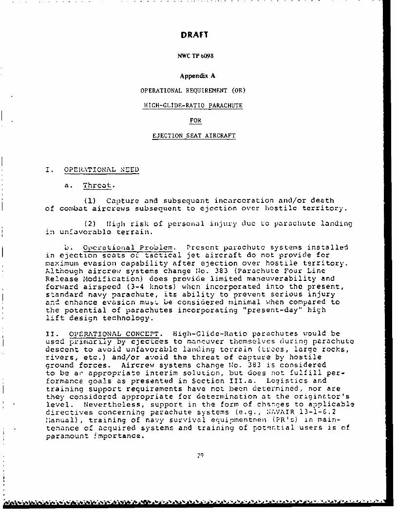
ýppcoidix A contains the CNO Draft ').erational Requirement (OR) for HighGlide--Ratio Parachute in Ejection Seat Aircraft. The OR addresses some of the problemswith the 28FC canopy and the situations that would require the use of a high-glidecanopy. Although this version of the OR was recently cancelled, it is presently beingrewritten. It is anticipated that a new OR will cover approximately the same points.
TEST ITEMS
Pilot Chute Controlled Reefing as described above was used on the majority of theparachutes for the first 26 tests; at the end of this series of tests it was evident thata fundamental change in the reefing system would be necessary to make any furtherprogress.
Several variations of a fixed-length reefing line system severed by pyrotechniccutters were used subsequent to Test 2&, all of these systems used slider reefing inaddition to the fixed-length reefing line. These systems are fully described in thetest description section on each configuration.
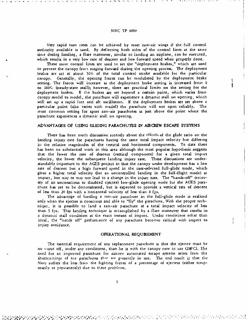
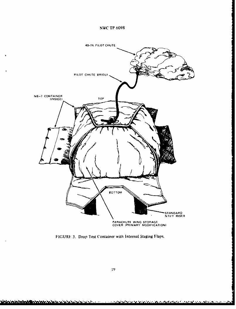
Most of the test parachutes were packed in NB-7 back parachute containers modifiedwith the addition of internal staging flaps, which are used to hold the deployment bagin the pack tray until the pilot chute and bridle line have completely deployed (seeFigure 3). For one test on Configuration 13, the canopy was packed in a zcaledcontainer that was developed for the Maximum Performance Ejection Seat (MPES).This container measures 12 by 12 by 6 inches and requires pressure or vacuum packingfor either the 28FC or the AGES parachute. The pack volume of the AGES canopy wasapproximately 10% smaaller than the 2VFC when packed under identical conditions. Thistest was conducted using a Cylindrical Test Vehicle (CTV) rather than a torso dummy.
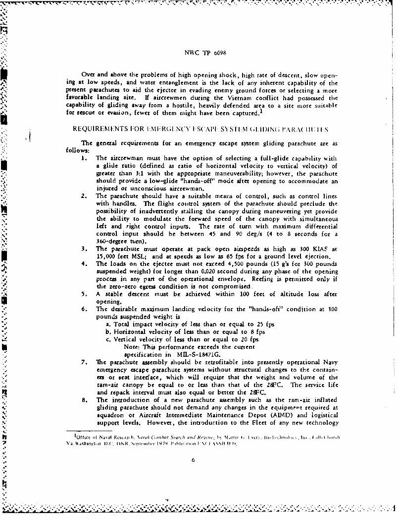
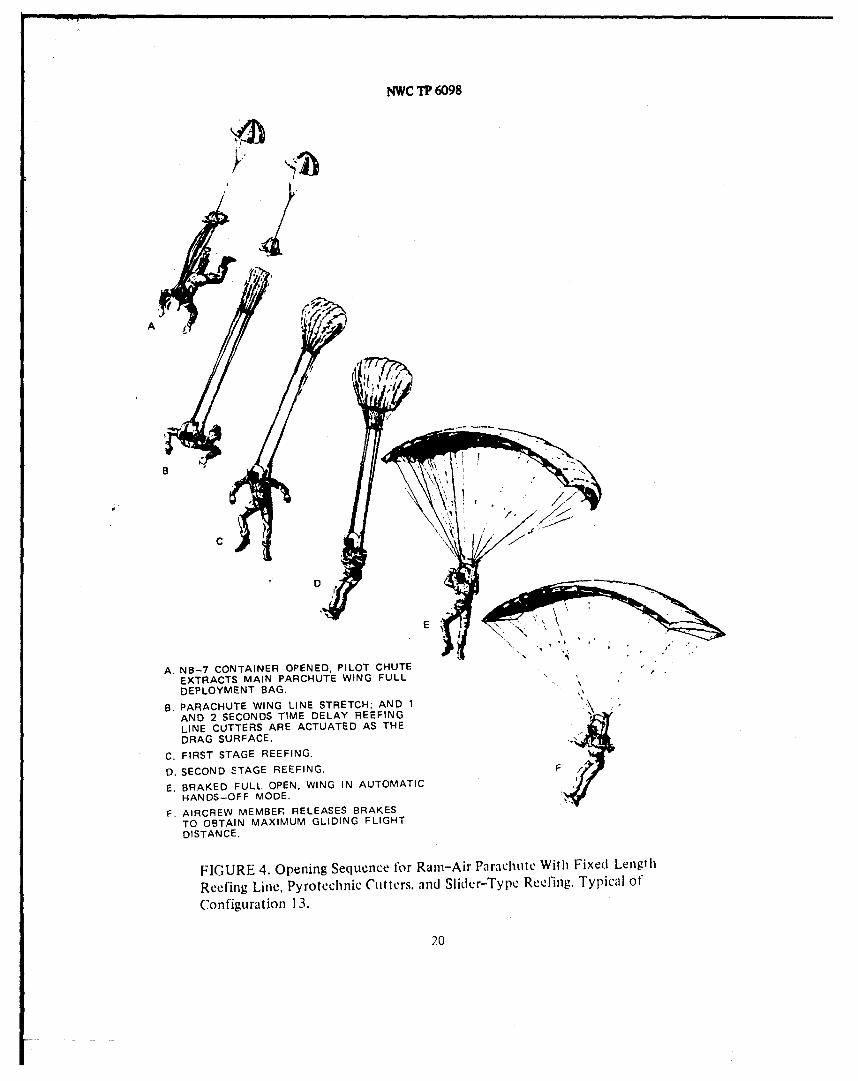
The deployment scquencc begins with static line or actuator opening of the pack;the pilot chute deploys and extracts the deployment bag. At line stretch, as the dragsurface is exposed, the cutters are initiated and the reefing system sequences to fullopen. In most instances, the canopy was deployed with the trailing edge deploymentbrakes set. During some of the tests, the pilot chute was released with a cutter inorder to let the PCR system fully retract; in other tests, cutters were used to releasetde deployment brakes or to set a turn condition to prevent the canopy from fly)ing offof the range. A typical opening sequence is shown in Figure 4.
SUPPORT EQUIPMENT
The following equipment was used during the torso dummy drop te3ts:1. Parhu $2
a. Co€ntinct All parachute wings were packed in a modified NB-7container (Figure 3), or a modified Mini-System container (very similar
7
NWC TP 6098
to NB-7) except for one test which used a cylindrical test vehicle (CTV).b. Deployment Initiator. A static line pack opening system was used forall airdrops from the U-1B, C-8 and C-117 aircraft as well as the lasttwo drops from the A-3. Model 1000 HiTek parachute actuators with a 0.75second time delay were used on the remaining A-3 aircraft drop tests. Anaft door release system was used for the F-4 aircraft CTV test.c. Pilot Parachute Reinforced 40-inch pilot parachutes from the A-7aircraft braking parachute assembly and other similar types were used forall tests.d. Pylotechnic cutters Pencil type reefing line cutters of various sizesand time delays were used to release the pilot parachute after full infla-tion, release deployment brakes after full-braked inflation, release thereefing rope after full inflation, and provide the time sequencing for thereefing system on the last ten tests.
2. Test Loads Torso dummies ranging in weight from 171 to 400 pounds, includ-ing canopy and instrumentation, were used except for the one test which used a
CTV. The CTV test was to verify that the AGES canopy was compatible withthe sealed pack developed for MPES.
3. Drop Test Aircraft. Tests were conducted from the U-1B, C-8, C-117, A-3,and F-4 aircraft.
4. Launch Devices A rack dividing the bomb bay into four compartments(coffins) was used for gravity drop tests from the A-3. No special equipmentwas required on the other aircraft.
5. Photographic Equipment. A minimum of three Askania Cinetheodolite cameraswere used to obtain space positioning data on all but the last five tests.Frame rate was 5 fps during the opening sequence. Either 16-mm or 35-mmcameras were used to record event times; 16-mm cameras were used for ground-to-air and air-to-air coverage; a variety of still cameras were used forvarious phases of the documentation.
6. Telemetry EQuipmen= 7500-pound capacity strain-gage links were installed onthe parachute risers; and three-axis acclerometers were installed in the chestcavity of each dummy. The accelerometer data were used as a cross-check onthe strain-gage data.
DROP TEST IPRO0tIM: RE
Thirty-seven drop tests using torso dummies and a CTV were made under a varietyof conditions; in all, thirteen different canopy configurations have been tested.
The torso dummies were pushed out of the side door of the U-lB and the C-117,and off of the tailgate of the C-8 Buffalo; the packs were opened using a conventionalbreak-cord type static line.
In the A-3 aircraft, the dummies were gravity launched from a compartmentedrack in the bomb bay. The automatic actuator was armed by a short static line hookedto the aircraft structure and opened the pack 0.75-second after arming.
For the CTV test using the F-4 aircraft, the CTV was dropped from the center-line bomb rack; the aft door of the CTV was ejected after a 1-second delay which releas-ed the pilot parachute and started the deployment from the sealed container.
8
*16e
Xh ~ *- . .. ' %% . . -
NWC 1? 6098
TEST CONDITIONS AND RESULTS
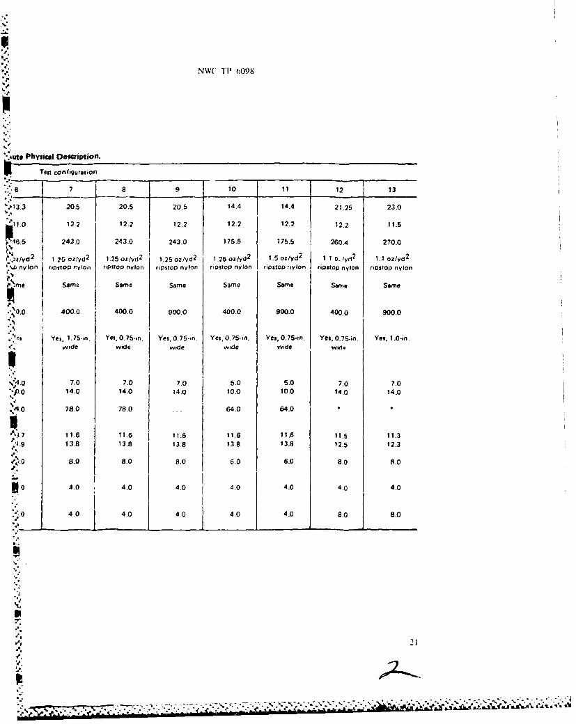
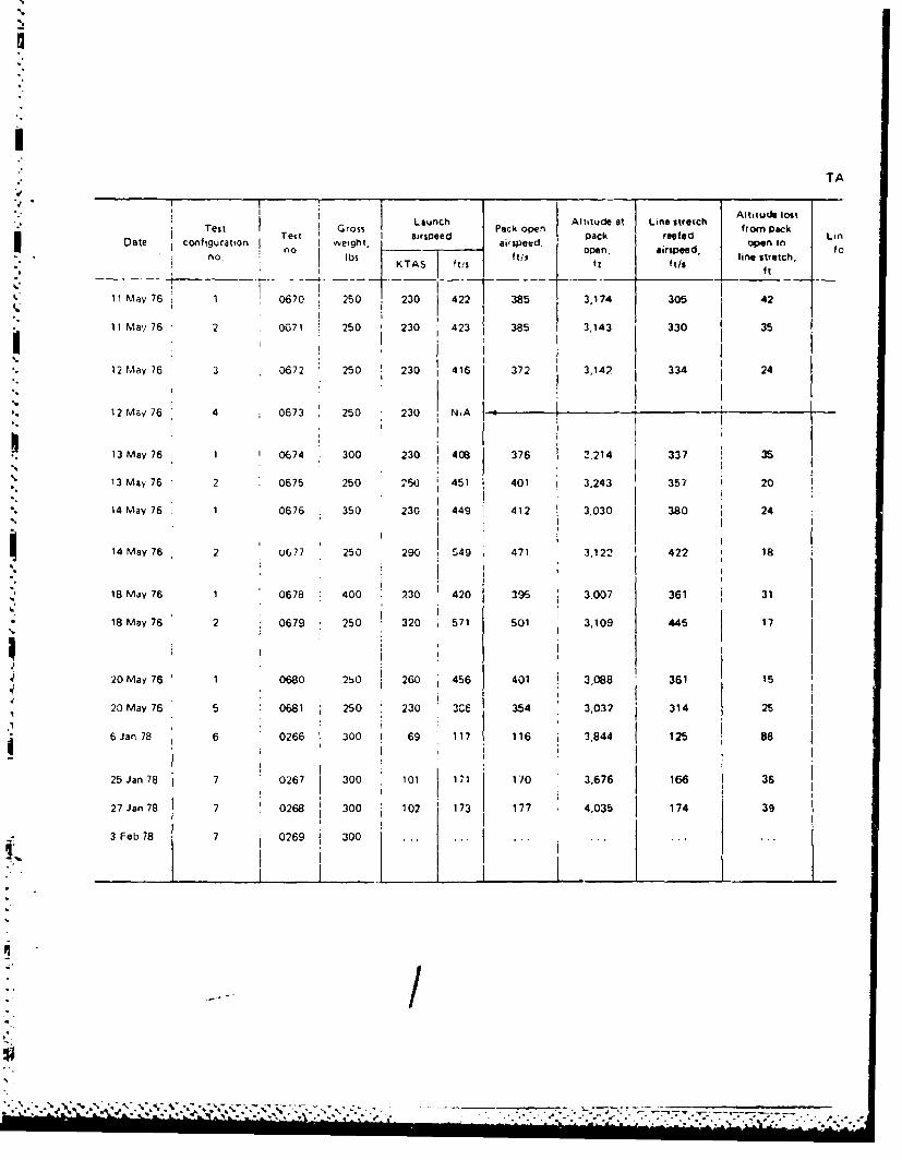
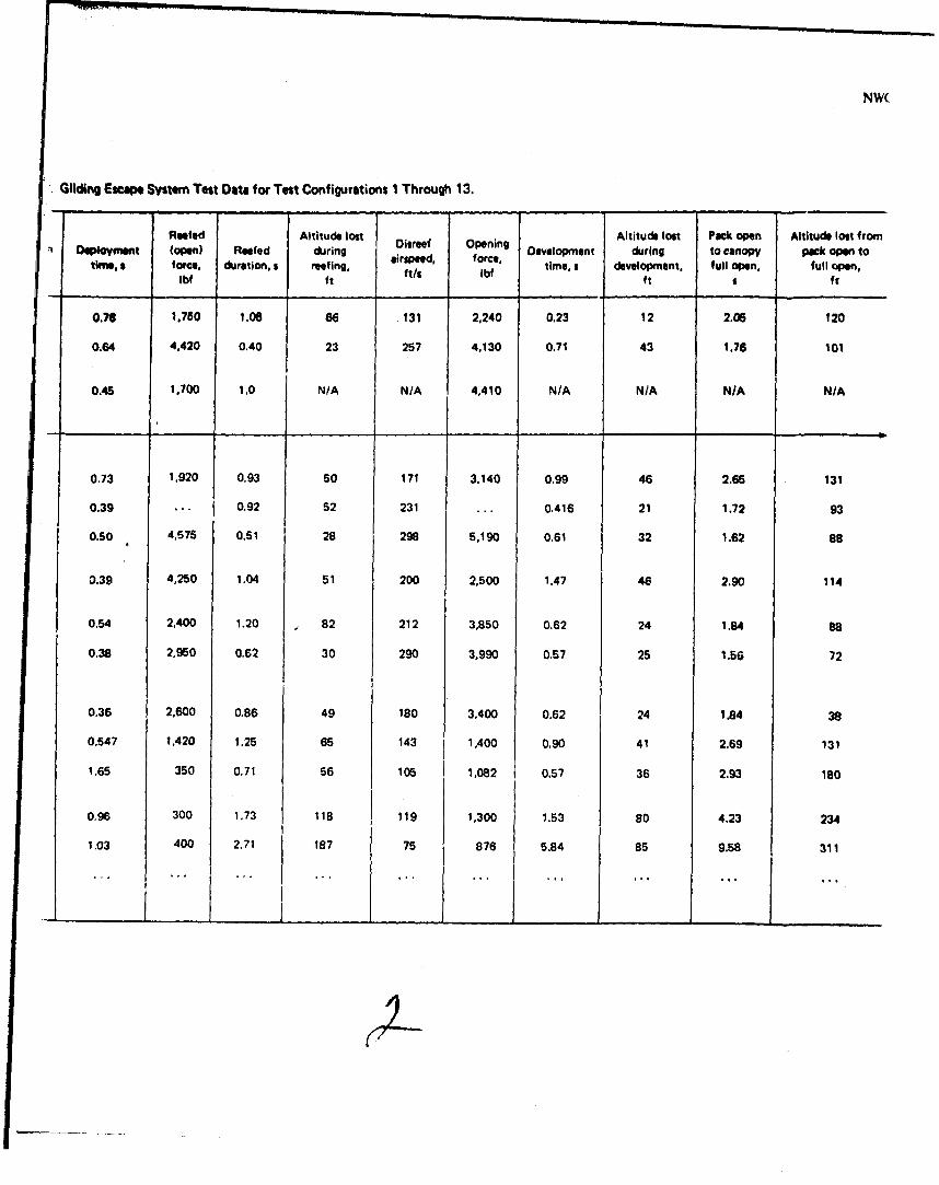
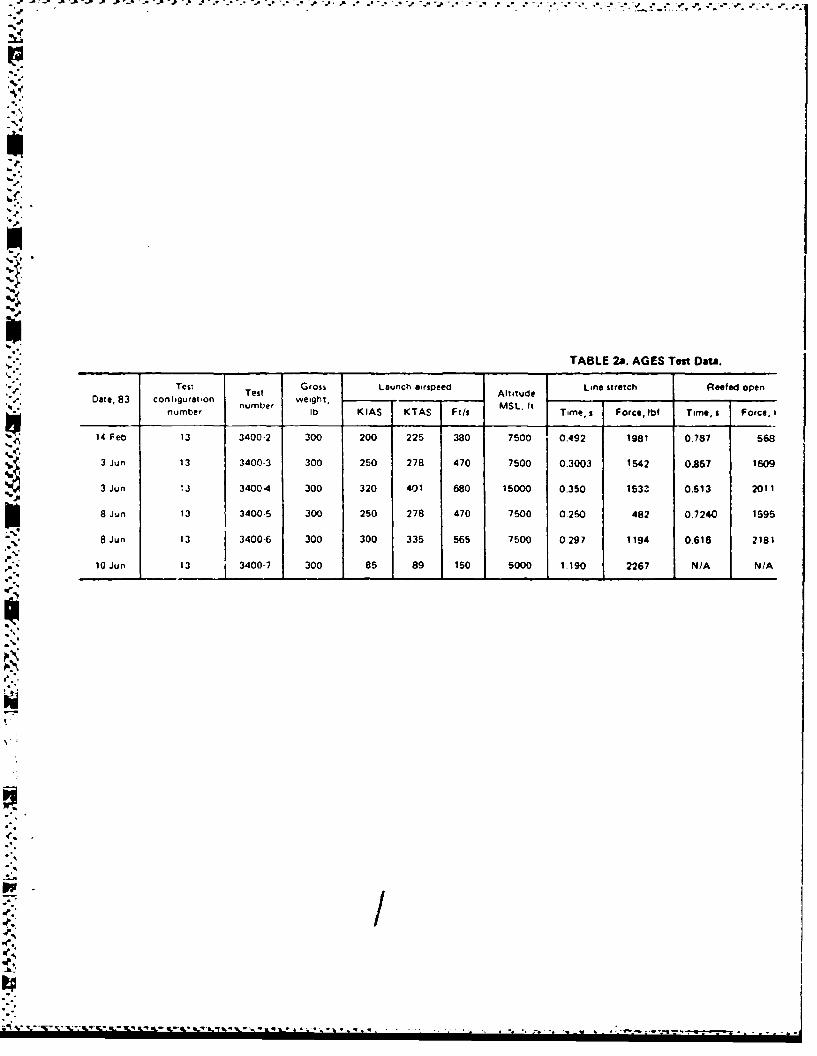
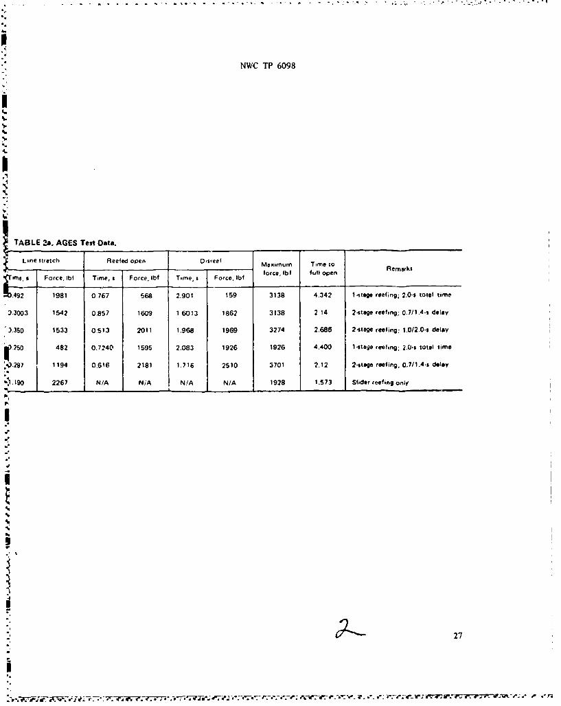
The following sections describe the parachute used in each configuration and abrief discussion of the tests conducted with each configuration and the results. Tab 1 eI lists the physical parameters for each configuration; Table 2 lists the test condi-tions and data extracted for each test conducted. The airspeeds listed are in knots trueairspeed at pack opening unless otherwise indicated.
Packing procedures were identical with those used for standard sport parachutewings, except for the last 11 tests, which used a fixed-length reefing line (with pyro-technic cutters) and a slider.
CONFIGURATION 1
Descrii . Commercially available heavy-duty Strato-Cloud canopy with deploymentbag and ropes and rings reefing system; seven-cell canopy with approximately240-square-foot surface area.Te&st I=or.sc To obtain data regarding the effects on opening dynamics in regard tochanges in gross weight; and data on high airspeed deployment dynamics.Test Conditions: Test No. Weight. lb Airspeed, KTAS
0670 250 2300674 300 2300676 350 2300678 400 2300680 250 260
Test Results Test numbers 0670, 0674, 0676 and 0678 performed satisfactorily withoutdamage. The high reefed force of 4,585 pounds and opening force of 5,190 pounds thatwere recorded during test 0676 were attributed to the blanketing of the pilot parachuteby the deployment bag. Test No. 0680 functioned as intended at the higher launch air-speed.st Conclusions The varying of the gross weights from 250 to 400 pounds at the same
launch speed does not noticeablyaffect the deployment dynamics of the parachute wing;conversely, it was evident that increasing the airspeed does change the deploymentdynamics.
CONFIGURATION 2
Dcsgription. Commerci'., available heavy-duty Strato-Cloud parachute with deplo7-merit bag and ropes and rings reefing system; se'en-cell canopy with approximately 240square-foot surface area.Test PurpD•s, To obtain data regarding the effects on opening dynamics in regard tochanges in airspeed witb no changes in gross weight.Test Conditions: Test No. Weight. lb Airspeed. KTAS
0671 250 2300675 250 2600677 250 2900679 250 320
Individual Test Results Tests 0671 and 0679 resulted in major dan, age; tests 0675 and0677 were not damaged.
9
NWC 1? 6098
Test Conclusions. The launch airspeeds were varied in 30-knot increments with aconstant suspended weight of 250 pounds. As expected, the test results revealed that thedeployment dynamics become unpredictable and unreliable at pack-open airspeeds above250 KTAS. The cell openings received major damage from the high dynamic pressurebefore and during the reefing sequencing. The drag of the pilot parachute, not measuredseparately, is believed to add significantly to the total snatch and reefed forces.Blanketing of the pilot parachute by the deployment bag will reduce the effectiveness ofthe PCR system and increase the opening force.
5-
CONFIGURATION 3
PIPDesc . A standard sport Strato-Cloud parachute was modified from a seven- to afive-large-cell parachute wing by removing two complete cells and the half-cell ribsfrom the remaining cells. A deployment bag was used and the slider was held in placeat the stabilizer stop rings and released by 4-second pyrotechnic cutters. The para-chute had a surface area of approximately 150 square feet.Imt Puz sc. To obtain deployment and reefing data on a parachute constructed withouthalf ribs.Test Conditions: Test No. Weight. lb Airspeed. KTAS
0672 250 230TIeLsReisLts Major damage was sustained during the reefed portion of the openingsequence; the parachute remained partially inflated until impact.Test Concluvsio It is believed that the damage was caused by the use of single largecells rather than the standard cells with a center divider rib.
CONFIGURATION 4
Qjaipji A square planform parachute (aspect ratio=1.0) was used with a deploymentbag; the slider was held in place at the stabilizer stop rings and released by two1.2-second cutters.Test Paose To obtain deployment and reefing data on a square planform parachute.Test Conditions: Test No. Weight - lb Airsoced. KTAS
0673 250 230Individual Test Results. Major damage was sustained during reefing and filling onTest 0673.Test Conclusions It is believed that the damage was caused primarily by the reefingsystem used and was not related to the lower aspect ratio when compared to the otherconfigurations.
CONFIGURATION 5
Dim iimi. CommetciaUy available Strato-Star canopy, with deployment bag andropes and rings reefing system. Planform area of the Strato-Star is approximately 195square feet.Test P os. To obtain further data on the deployment characteristics of rope andrings reefing system.Test Conditions: Test No. Weight. lb Airspeed. KTAS
0681 250 230pr
10
J
-'€ '' r ,.$1..p •,' ,,•,• • • .. • . ' ,• ' ,,.•', ' ,. .,.- . . . -,,_, .. . .
I-
NWC 1P 6098
Individual Test Results Test No. 0681 functioned as intended with no damage.Test Conclusions, Test No. 0681 demonstrated that pack opening airspeeds of 200 KTASare within the capabilities of this standard sport parachute using the cope and ringsrcefing system.
CONFIGURATION 6
Descriotion. A heavy-duty five-cel, patarhute wing with rope and rings reefing systembut no deployment bag. The deployment brakes weic rcleased using 4-scrond delaycutters. The planform area of this canopy wa& approximately 146 square feet.T To obtain data on the deployment characteristics, reding perfornance,rate of descent, and full-glide capabilities of a small five-cell canopy.Test Conditions: Test No. Weiaht. lb Airspeed. KTAS
0266 300 690271 171 114
Individual Test Results. On Test No. 0266 the pilot chute was not fully rctracted bythe rope and rings reefing system, and the left end cell remained partially closed,The deployment brakes were released by cutters as designed. On Test N(. 0271, the tcrf-ing and brake release functioned as planned.Test Conclusions The rate of descent requirements as stated in the OpetationalRequirements may possibly be obtained with a five-cell parachute wing.
CONFICURATION 7
Decription. Two major advancemenu in the state-of-the-art sport parachlute canopycloth and fabrication techniques were used in the conwtruction of tht. canopy, 111cstandard 1.5-oz/yd nylon ripstop was replaced by a 1.25-oz/yd nylon ripatop cloth. 'ibisparachute wing was identical to the lightweight military Suato Cloud canopies thatwere being evaluated for high-altitude offset insertion parachute operations at theArmy's Special Forces School. Rope and tings reefing without a deployment bag wasused. The planform area of this parachute is Approximately 240 square feet.
Test Putpo. To evaluate the new material arid fabrication techniques and obtai,further data on the rope and rings reefinp sy5tem.Test Conditions: Test No. Weight. lb Airspeed. KTAS
0267 300 1010268 300 !020269 300 .
0270 300 ZZ90272 300 3200273 300 345
Individual Test Results On Test No. 0267, low-speed deploymaent, reefing, asid brakedfull-open data were obtained. On Test No. 0268 and 0270, tde effects of iicicaerd Iparkopen airspeed and full-glide performance data were obtained. On Test No. 02f,9 tlereserve parachute deployed immediately after lamich, ntecluding tie colleclio, of asyuseful data. Similarly, data from Test No. 0272 wcrc not available becauCS the pilotparachute released at the moment of pilot parachate/reefing line stretch, asd tie wiMlkruptured. On Test No. 0273, high-speed film coverage revealed that maj•r da.,oX
11
-S - . . ,. .
NWC TP 6098
occurred at line stretch and during the partially reefed opening. The damage was soextensive that no specific, logical engineering redesign or modification informationcould be obtained; the canopy did not remain inflated.Test Conclusions, It was concluded that the new materials and fabrication techniquesdid not adversely affect the deployment, reefing and braked full-open performance withinthe operational envelope of the rope and rings reefing system.
CONFIGURATION 8
QusrwlJQD, This was the first heavy-duty design of the military StratoCloud para-chute using the 125-oz/yd nylon ripstop cloth. The rope and rings reefing system wasused without a deployment bag. The planform area of this parachute is approximately240 square feet.TIMLP-I ose To obtain data on structural integrity, deployment characteristics andreefing dynamics.Test Conditions: Test No. Weight. lb Airsoeed KTAS
0274 300 353Individual Test Results During Test No. 0274 major damage was sustained at linestretch, and the wing streamered until the reserve parachute deployed at approximately1,000 feet AGL. High-speed film coverage and post-test inspection of the assembly didnot reveal a specific cause of the failure relating to the unique features of this config-bration. It is believed that the two center suspension lines (400 pound tensilestrength) and the associated reefing ring attachments failed first.Test Conclusions. Suspension line breaking strength was inadequate and was increased to600 pounds for subsequent tests.
CONFIGURATION 9
Description. The suspension lines of the heavy-duty military Strato-Cloud parachutetested as configuration number 8 were changed from 400 to 600 pounds breaking strength.Rope and rings reefing without a deployment bag was used.Test P ose. To obtain structural, reefing, and deployment data.Test Conditions: Test No. Weight. lb Airsneed, KTAS
0275 300 3720699 300 308
Individual Test Results. Test No. 0275 was inadvertently conducted at airspeeds fasterthan planned. Although the parachute wing sustained major damage during reefed openingand canopy development, it remained inflated. On Test No. 0699, the pilot parachutereleased prematurely at line stretch, the parachute wing ruptured, and no test data wereobtained.Test Conclusions. The rope and rings reefing system becomes unpredictable during highairspeed deployments.
CONFIGURATION 10
Description. Two cells were removed from the heavy-duty military Strato-Cloud canopy(configuration No. 8); this canopy used rope and rings reefing without a deployment bag.The planform area of this parachute war approximately 175 square feet.
12
NWC TP 6098
Telt. P ose The two cells were removed to determine if this method could be usedto reduce weight and bulk and still remain within the desired performance parameters.Test Condition. Test No. Weight. lb Ainpeed. KTAS
0002 300 1000067 300 91
Individual Test Results, On Test No. 0002, the wing was deployed with an excessivedeployment brake setting, and the parachute descended in the stalled condition. On TestNo. 0067 the wing deployed successfully.Test Conclusions There seem to be no new apparent deployment reefing or brakedfull-open problems related to a five-cell canopy as compared to a seven-cell canopy.
CONFIGURATION 11
Description. A heavy-duty five-cell parachute was fabricated that included all of thepreviously developed changes affecting the structural integrity and performance. Ropeand rings reefing system was used without a deployment bag. The planform area of thisparachute was approximately 175 square feet.Test To determine whether a five-cell parachute wing could be used to reducethe weight and bulk but keep the performance within the desired limits.Test Conditions, Test No. Weight. lb Airjaeed. KTAS
001 300 353Individual Test Result, On Test No. 001 the parachute wing began to rupture shortlyafter line stretch; then streamered until impact. Post-test inspection revealed thatone front suspension line and both lower control lines had failed.Test C nclusions The rope and rings reefing system performance, which was predict-able and reliable to approximately 200 KTAS launch speeds, is inadequate above thisspeed. A different reefing system must be developed for use at speeds above 200 KTAS.
CONFICURATION 12
Description A heavy-duty seven-cell parachute was fabricated, which included all ofthe previously developed changes affecting the structural integrity of the parachute; animportant change was an increase in the strength of the reinforcing tapes used on theleading edge. A two-stage reefing system was used; the first-stage reefing line was3.25 feet long and passed through the rings on the lower surface periphery of the canopyand the rings )n the top leading edge of each of the half-cells. The second-stage reef-ing line was 6 feet long and passed through the four grommets in the comers of theslider and through the four slider stop rings on the lower edge of the stabilizer panels.Both reefing line cutters were armed at line stretch (deployment bag opening); thefirst-stage delay was 2.0 seconds, and the second-stage delay was 4.0 seconds. The plan-form area of this canopy was approximately 260 square feet.Test Purpose. To test the two-stage reefing system for high airspeed deployments.Test Conditions: Test No. Weight. lb Airsoced. KTAS
0610A 300 3410610B 300 338
Individual Test Results. On Test No. 0610A the canopy was dumped from the deploy-ment bag before line stretch; this precluded an orderly, lines-first deploymentsequence. High-speed film coverage revealed that only one reefed stage was evident.
13

NWC 1P 6098
The parachute wing received major damage but approximately 805 of the canopy remained
inflated. Post-test inspection revealed that the reefing system had malfunctioned. OnTest No. 0610B the parachute functioned as designed; however, the telemetry system mal-functioned and no telemetry data were obtained.Test Conclusions The structure of the deployment bag must be strengthtned in orderto ensure that the canopy stays in the deployment bag during the deployment sequence.The fixed-length reefing system shows promise but this particular method is nrorne toentanglement with the slider; a different method was devised for the nextconfiguration. Although, the canopy in Test No. 0610A suffered extensive damage duringd--ployment, it remained inflated and had a stable descent with a slight turn; this was
probably a survivable malfunction.
CONFIGURATION 13
Dmaiption. A new design, heavy-duty seven-cell parachute wing using a Lissaman 7808airfoil, spanwise construction for the top and bottom surfaces, full deployment bag, andtwo-stage reefing, was constructed by Para-Flite, Inc. Two slightly different config-urations of this reefing system, both of which make use of rings installed around thelower periphery of the canopy and on the upper leading edge of each half-cell at theintersection of the nonloaded rib, were used successully on configuration 13. A ring isalso installed on the center of the slider and is used to hold the slider in place untilthe reefing line is severed. Redundant cutets are used at all locations.
The two-stage reefing system works as follows: The first-stage reefing line ispassed through the reefing rings on the lower leading edge of each main cell at thesuspension line attachment point and through the rings on the upper leading edge of eachhalf cell. The line is alternately routed through the upper and lower rings, then drawndown to approximately 8 inches. The first stage serves to keep the cell openings dosedduring the initial exposure of the drag surface; time delays of 1.0 and 0.7 seconds havebeen used successfully for the first stage.
The second-stage reefing line is passed through the rings on the lower leadingedge, then around the lower periphery of the canopy; the slider is held up agairst thelower surface of the canopy by the second-stage reefing line, which passes through thering installed on the center of the slider. The length of the second-stage t-efing lineis 3.25 feet. Second-stage time delays of 2.0 and 1.4 seconds have been used success-fully; both the first- and second-stage cutters are activated at line stretch as thecanopy emerges from the deployment bag.
The single-stage reefing system is similar to the second-stage of the systemabove; the difference is that the rings on the upper leading edge of the half-cells arealso threaded onto the reefing line for the single-stage system. This system keeps thenose openings closed until full disreef, whereas the two-stage system releases the noseopenings when the first stage disreefs.
For most of these tests the canopies were packed in a modified NB-7 or modifiedMini-System container; however, on Test No. 1405, the parachute was packed in a sealedcontainer after pressure packing. The packed volume was approximately 10% less thanthat of the 28FC when packed under the same conditions of pressure and vacuum.Tetu &RoseI To test an improved two-stage reefing system for high airspeeddeployments; to test shorter total reefing times for the two-stage system; to test a
14 '
*~***%*"......................- ...
NWC TP 6098
single-stage reefing system with varying total reding times; and to demonstrate corn-patibility with the sealed pack system developed for the MPES project.
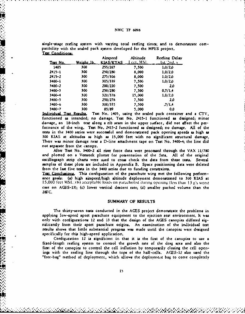
AIt Conditions,Airspeed Altitude Reding Delay
Test N.W Weight-lb. KIAS/KTAS I 'l. -NISI jIj ."1405 300 255/267 7,500 1.0/2.0
2415-1 300 250/280 8,000 1.0/2.02415-2 300 275/306 8,000 1.0/2.03400-1 300 305/339 7,500 1.0/2.03400-2 300 200/220 7,500 2.03400-3 300 250/280 7,500 0.7/1.43400-4 300 320/378 15,000 1.0/2.03400-5 300 250/278 7,500 2.03400-6 300 300/335 7,500 .7/1.43400-7 300 85/89 5,000 0.0
-Individual Test Results Test No. 1405, using the sealed pack container and a CTV,functioned as intended; no damage. Test No. 2415-1 functioned as designed; minordamage, an 18-inch tear along a rib seam in the upper ;urface, did not affect the pet-formancc of the wing. Teat No. 2415-2 functioned as designed; no damage. All of thetests in the 3400 series were successful and demonsruated pack opening speeds as high u300 KIAS at altitudes as high a 15,000 feet with no significant structural damage.There was minor damage near a D-line attachment tape on Test No. 3400-4; the line didnot separate from the canopy.
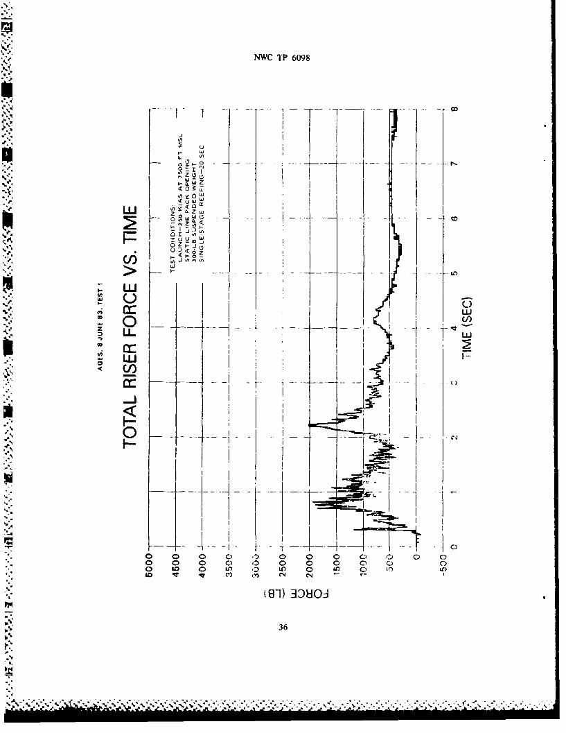
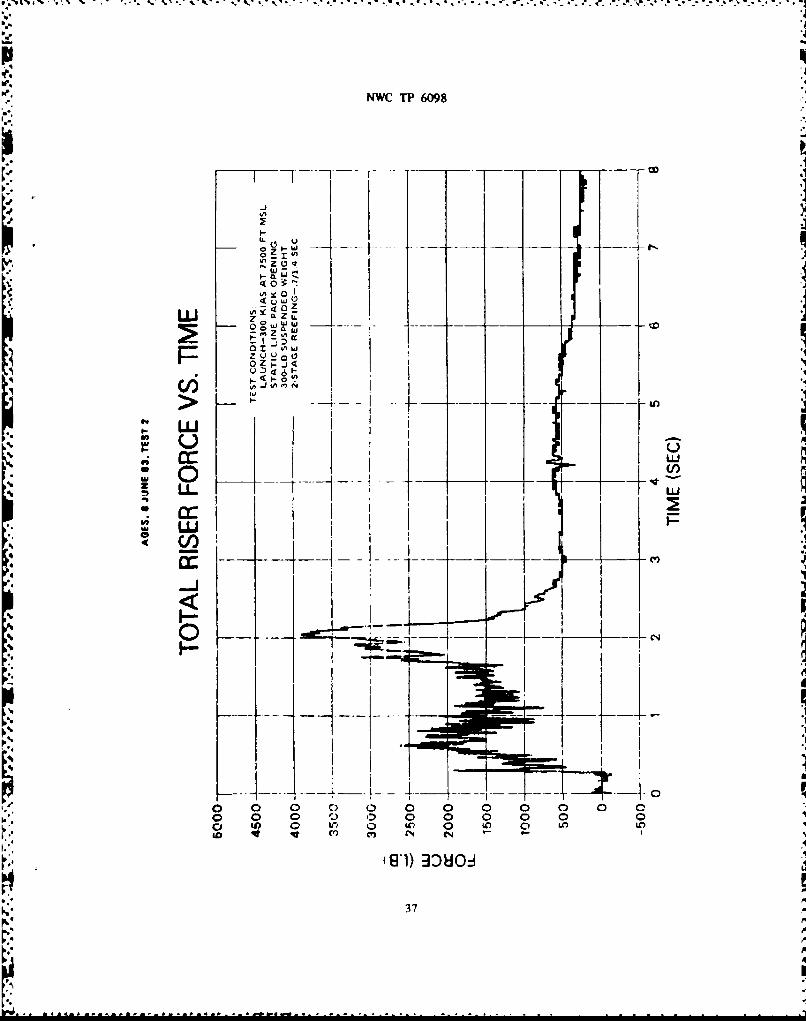
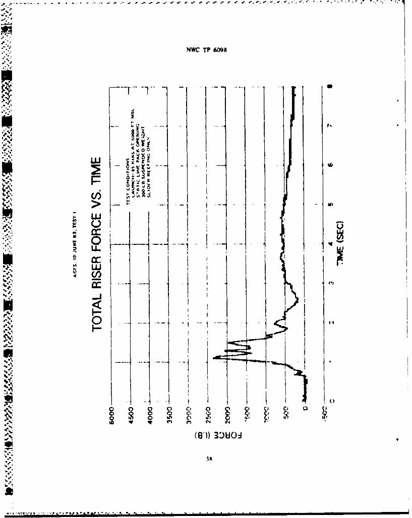
After Test No. 3400-2 all riser force data were processed through the VAX 11/780i and plotted on a Versatek plotter for presentation of the ite., All of the original"oscillograph strip charts were used to cross check the data from these tests. Severalsamples of thee plots are included in Appendix B. Space positioning data were deleted
from the lat five tests in the 3400 series due to funding constraints.
Test Conclusions. This configuration of the parachute wing met the following perform-ance goals: (a) high airspeed/high altitude deployment demonstrated to 300 KIAS at15,000 fcet MSI.: (h) acceptable loads on parachutist during opening (less than 13 g's worst"case on AGES-13); (c) lower vertical descent rate; (d) smaller packed volume than the28FC.
"SUMMARY OF RESULTS
The thirty-seven tests conducted in the AGES project demonstrate the problems inapplying low-speed sport parachute equipment to the ejection sear environment. It wasonly with configurations 12 and 13 that the design of the AGES canopies differed sig-
"" nificantly from their sport parachute origins. An ezamination of the individual tcst"results shows that little substantial progress was made until the canopies were designed"specifically for this high-speed application.
Configuration 12 is significant in that it is the first of the canopies to use afixed-length reefing system to control the growth rate of the drag area and also thefirst of the canopies to control the cell inflation by temporarily closing the cell open-ings with the reefing line through the tops of the half-cells. AGES-12 also used the"free-bag" method of deployment, which allows the deploymeit bag to come completely
K'..
NWC TP 6098
4t
off the opening parachute, thus reducing the snatch force due to pilot parachute loadingand reducing chances of entanglement.
Configuration 13 is the most successful of the canopies used in the AGES project;"there have been no structural failures and no malfunctions of the parachute. AGES-13uses a specialized, spanwise construction technique to form the top and bottom surfaces.
•This technique alHjws the use of continuous reinforcing tapes across the full width ofthe parachute at the leading edge and at all line attachment points. The spanwise con-muction results in a much stronger parachute with no increase in bulk over conven-tional consruction methods. AGES-13 also controls the drag area growth withfixed-length reefing lines using the system described under Test Conditions andReiulu.
CONCLUSIONS
1. Based on the exploratory development phase of this project, it has been demon-strated that it is feasible to incorporate a ram-air inflated, gliding para-chute wing into a contemporary ejection seat aircraft escape system.
7. The AGES parachute (configuration 13) has met these performance goals:a. Structural integrity has been demonstrated at speeds up to 300 KIAS
(378 KTAS) at altitudes up to 15,000 feet NISL.b. Opening forces on the parachutist of less than 13 g's have been demon-
strated for the most severe case to date.c. Vertical rate-of-descent of 16 fps has been demonstrated at 300 pounds
suspended weight (corrected to sea level conditions).d. Pack volume of 10% lces than the 28FC when packed under the same condi-
tions.
RECOMMENDATIONS
Two major areas should be investigated during FY 1984. Full-scale engineeringdevelopment could begin in FY 1985 if these goals can be met in FY 1984.
1. Development and demonstration of a reefing system that is effective at 300KIAS without compromising the zero-zero ejection condition.
2. Development and demonstration of the capability to deploy the parachute in aminimum glide condition with a glide ratio of less than 0.5:1 in the"hands-off" condition, with the user-selectable option of a high-glide mode,capable of a glide ratio of 3:1 or higher.
16
_I .-. '. .. . .,. .'-.- -. .: ,.,'.,:, • ,, . . ',•, -, .. ,. ,. .: . -. ,. :. ,• ,,-, :.'., . . . ,- f , -: :.
NWC TP 6098
HALF CELL REEFING RINGS
HALF CELLMAIN CELL REEFING RINGSFULC L
SUSPESIONLINE
SLIDERN EDG TGUDL RTIEGTH
CONTRO CONTALNLLE
ASPECTIO LINES2.u.
FIGURE~~~~~~~~~~(0 LB. O(4r0l N)wo a-i nltd ldn aaht ig
SLIER FNSLE TREGTH
P. NWC TP 609H
LEADING EDGE .xI
7 I
.1 LINE
V k' // //" GUIDE PORTS
6~~ ~'IUPPER CONTROL
LINE
STABILIZER PANEL-I II,DPOMENT
RISER -CONTROL LINE HANDLE
LOWER CONTROL LINE
FIUE2 od np ihKKReig
NWC TP 6098
4o-!N. PILOT CHUTE
NBI-7 CONTAINERIiNSIDE) TOP
IRTTOM
S"" "•"="•S TAN DA RD
NfVY RISER
PARACHUTE WING STORAGECOVER (PRIMARY MODIFICATION)
FIGURE 3. Drop Test Container with Internal Staging Flaps,
19
.e ., ,• '4 '4..-4p.4 . , P p , , ' " . d * ,p .,. • " " .. .
NWC TP 6098
A £
/ /
D
E ,
A. NB-7 CONTAINER OPENED, PILOT CHUTEEXTRACTS MAIN PARCHUTE WING FULLDEPLOYMENT BAG.
B. PARACHUTE WING LINE STRETCH; AND 1AND 2 SECONDS TIME DELAY REEFINGLINE CUTTERS ARE ACTUATED AS THEDRAG SURFACE.
C. FIRST STAGE REEFING. i ,D. SECOND STAGE REEFING. F
E. BRAKED FULL, OPEN, WING IN AUTOMATICHANDS-OFF MODE.
F. AIRCREW MEMBER RELEASES BRAKESTO OBTAIN MAXIMUM GLIDING FLIGHTDISTANCE.
FIGURE 4. Opening Sequence for Ram-Air Parachute With Fixed Length
Reefing Line, Pyrotechnic Cutters, and Slider-Type Reefing. Typical of
Configuration 13.
20
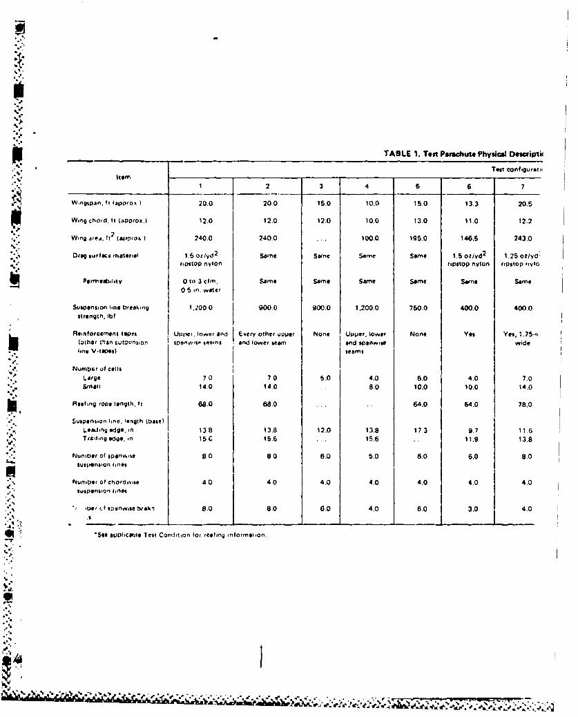
"TABLE 1. Test Parachute Physical DeOuriptik
Test conftgurati(
1"{12 3 4 6 6 7
Wingspan. It lapprox I 20.0 20.0 15.0 10.0 15.0 13.3 20.5
Wrng chord, II (approx.) 12.0 12.0 12.0 10.0 13.0 11.0 12.2
"" Wing area. 't2 (apvtrox) 240.0 240.0 ... 100.0 195.0 146.6 243.0
"Oreg surface material 1.6 oz/yd2
Some Se Same Seime 1.5 oz/yd2
1.25 oz/yd:nsritOD nylon ripstop nylon ripstop inylo
Permegably 0 to 3 cfm, Sarme Same Same Same Some Same0.5 in. water
Suspension line breakring 1,200.0 900.0 900.0 1,200.0 750.0 400.0 400.0strength. fbf
Reinforceyment tapes Uet,', lower and Eviery other upper None Upper, lower None Yes Yes, :.75."tothor than ;uSD.'ont•siv S w rnls and lower seam and sPanw-ge wideline V-ilKeel) seems
Number of cellsLarge 70 7.0 5.0 4.0 5.0 4.0 7.0small 14.0 14.0 ... 8.0 10.0 10.0 14.0
Roeling rope length, ft 68.0 88.0 64.0 64.0 78.0
Suspension line, length (base)6.e f,nlg edge, in 138 13.8 12.0 13.8 17.3 9.7 111.6Ted.lng edge. in 15.C 15.6 . . 15.6 . . . 11.9 13.8
Number of sponrhre 8 0 8.0 6.0 5.0 6.0 6.0 8.0suspension lines
Number of chordwize 4 0 40 4.0 4.0 4.0 4.0 4.0suspension ines
.",Ler •t esnwite br,,k 8.0 8.0 6.0 4.0 6.0 3.0 4.0
*See $VPPhCtlel Tell Cond•tion for reeling information.
A & '.
NW( TV 6098
.'Qt# Physical Description.
Tesi configuration
-Z6 7 8 9 1 10 11 12 13
3.3 20.20.5 20.5 14.4 14.4 2125 23.0
"1 1.0 12.2 12.2 12.2 12.2 12.2 12.2 11.56'5 243.0 243.0 243.0 175.5 175.5 260.4 270.0
1.z/yd2 125 oz/yd2 1.25oz/yd
2 1.25oz/yd2 1.25oz/yd
2 1.1o0/yd2 1.1 O yd
2 1.1 0z/yd2
,%r, nylon r-psOP rylon rnpITop nylon ripstop nylon ripstop nylon riPStOP !iylon ripstop nylon ripIlop nylon
rne Same Some Same Same Same Sane Some
0,0 400.0 400 0 900.0 400.0 900.0 400.0 900.0
Ns Yes, 1.75-,n. Yes 0.75-in. Yes, 0.75-,n. Yes, 0.75-in. Yes, 0.75-in. Yes, 0.75.in. Yes, 1.0-in." r wide wide wide wide wide wicldSf
4.0 7.0 7.0 7.0 5.0 5,0 7.0 7.00,0 14.0 14.0 14-0 10.0 10W0 14.0 14.0
• .0 78.0 78.0 64.0 64.0
7 1 11.6 11.6 I 11.6 11.6 11.6 11.5 11.313.8 13.8 13.8 13.8 13.8 12.5 12.3%J8.0 8.0 8.0 6.0 6.0 8.0 8.0
4.0 I 4.0 4.0 4.0 4.0 4.0 4.0
0 4.0 4.0 4.0 4.0 4.0 8.0 8.0
I.
-'4
21% ,
k.-'.~ -
•°°
%
TA
' I Altituds lostLaunch ~Altitude at Line strecch Aliueos
"Test Gross uch Pack open from packTest airspeed Pack reefed Lin
Date configuration no weg tgo airspeed, A it en. Li r e~ , ofnr to L
no. lbs open aisft/F ft line stretch,o.IKTAS$ fts /$ tf, ft/$ft
S11 May 76 1 0670 250 230 422 385 3.174 305 42
11 May/ 76 2 0G71 250 230 423 385 3,143 330 35
12 May 76 3 0672 250 230 416 372 3,142 334 24
, 12 Mai 76 4 0673 250 230 N ;A Ii
13 May 76 1 0674 300 230 408 376 1 214 337 35
%' 13 May 76 2 0675 250 254 451 401 3,243 35i 20
14 May 76 1 0676 350 230 449 412 3,030 380 24
%
14 May 76 2 u677 250 290 549 471 3,122 422 1 18
18 May 76 1 0678 400 230 420 395 3,007 361 31
18 May 76 2 0679 250 320 571 501 3.109 445 17
20 May 76 1 0680 250 260 456 401 3,088 361
20 May 76 5 0681 250 230 456 354 3,032 314 25
6 Jan 78 6 0266 300 69 117 116 3,84 125 Be
25 Jan 7b 7 0267 300 101 170 3,676 166 36_ 127 Jan 78 7 10268 300 102 173 177 4,035 174 39
3 Feb 78 7 0269 300 .. ... .......
% •o
iT"
-..,.., , ,., .-,-,-.. , .... ,. ._..•. •. .... .•.. . .. . ..:• . • _, _•_ L __ ..:._.• .. ,• ..m.illi_ _
NW(
Gilding Escap" System Test Data for Test Configurations 1 Through 13.
Reefed Altitude lost Altitude lost Pack open Altitude Iost fromDeployment (open) Reefed during airsped fOen Development during to canopy pack open to
time, s force, duration. s reefing, ft/s obf time, $ development, full open, full open,lbf ft ft £ ft
0.6 1.750 1.06 66 131 2,240 0.23 12 2.06 120
0.64 4,420 0.40 23 257 4,130 0.71 43 1.76 101
0.45 1,700 1.0 N/A N/A 4,410 N/A N/A N/A N/A
0.73 1.920 0.93 50 171 3.140 0.99 46 2.65 131
0.39 ... 0.92 52 231 ... 0.416 21 1.72 93
0.50 4,576 0.51 28 298 5,190 0.61 32 1.62 88
3.39 4,250 1.04 51 200 2,500 1.47 46 2.90 114
0.54 2,400 1.20 82 212 3,850 0.62 24 1.84 88
0.38 2,950 0.62 30 290 3,990 0.57 25 1.56 72
0,36 2,600 0.86 49 180 3,400 0.62 24 1.84 38
0.547 1,420 1.25 65 143 1,400 0.90 41 2.69 131
1.65 350 0.71 56 105 1,082 0.57 36 2.93 180
0.96 300 1.73 118 119 1,300 1.53 80 4.23 234
1.03 400 2.71 187 75 876 5.84 85 9.58 311
_ _ _ I _ _ _ _ ~~~~I __ _ _ __ __ _ _
(A.
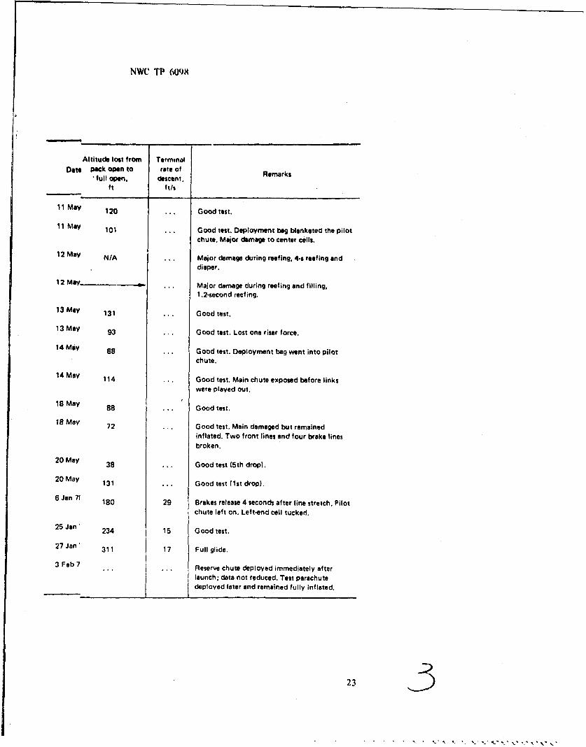
NWC TP (OJ)8J
Altitude lost from TerminalDate Pack open to rate of
full open, descent.ft ft/s
11 May 120 Good test.
11 May 101 Good test. Deployment beg blanketed the pilot
chute. Major damage to center cells.
12 May N/A ... Major damage during reefing, 4-s reefing and
diaper.
12 May ... Major damage during reefing and filling,
1.2-second reefing.
13 May 131 ... Good test.
13 May 93 ... Good test. Lost one riser force.
14 May 88 ... Good test. Deployment bag went into pilot
chute.
14 May 114 ... Good test. Main chute exposed before links
were played out.
18 May 88 ... Good test.
18 May 72 .. Good test. Main damaged but remained
inflated. Two front lines and four brake lines
broken.
20 May 38 ... Good test (5th drop).
20 May 131 ... Good test (1st drop).
6 Jan 7t 180 29 Brakes release 4 seconds after line stretch. Pilot
chute left on. Left-end cell tucked.
25 Jan' 234 15 Good test.
27 Jan ' 311 17 Full glide.
3 Feb 7 ,,. ... Reserve chute deployed immediately after
launch; data not reduced. Test parachutedeployed later and remained fully inflated.
235
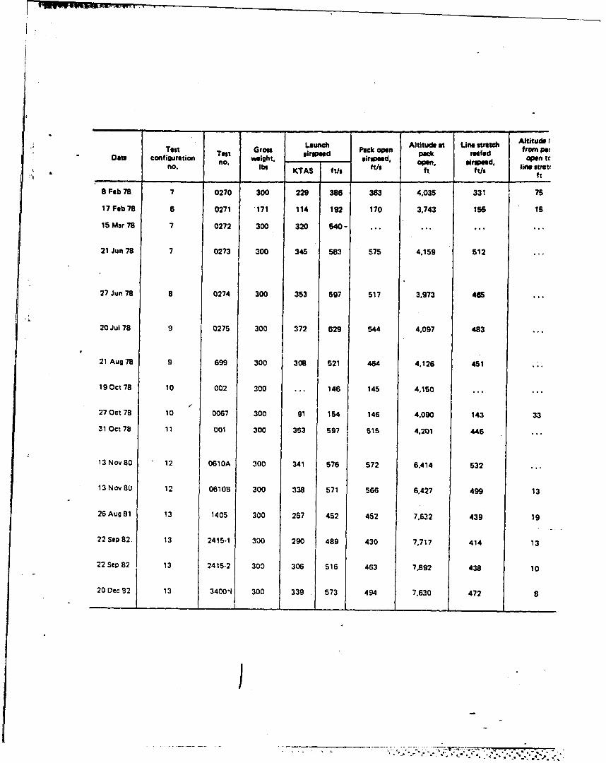
Launch Altitude at Line stretch Altitude ITest Test Gross altipeed Pack open peak reefed fropet
Data configuration no. weight, a, an tcno. We KTAS ft/$ We ft ft/s Jim stre
ft
8 Feb 78 7 0270 300 229 386 363 4,035 331 75
17 Feb 78 6 0271 171 114 192 170 3,743 155 15
15 Mar 78 7 0272 300 320 540- ......
21 Jun 78 7 0273 300 345 583 575 4,159 512
27 Jun 78 8 0274 300 353 597 517 3.973 465
20 Jul 78 9 0275 300 372 629 544 4,097 483
21 Aug 78 9 699 300 308 521 464 4.126 451
19Oct 78 10 002 300 ... 146 145 4,150
27 Oct 78 10 0067 300 91 154 146 4.090 143 33
31 Oct 78 11 001 300 353 597 515 4.201 446
13 Nov 80 12 0610A 300 341 576 572 6,414 532
13 Nov 80 12 06108 300 338 571 566 6,427 499 13
26Aug81 13 1405 300 267 452 452 7,632 439 19
22 Sep 82. 13 2415-1 300 290 489 430 7,717 414 13
22 Sep 82 13 2415-2 300 306 516 463 7,892 438 10
20 Dec 82 13 3400-1 300 339 573 494 7,630 472 8
J
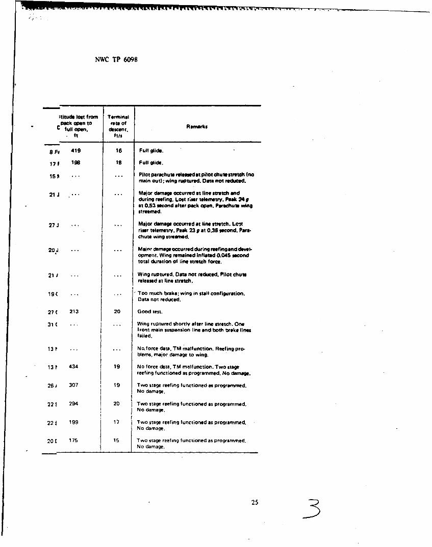
NWC TP 6098
Ititude lost from Terminalpack open to fate of RrakC full open, descent. erk
ft ft/s
9 Fi 419 16 Full glide.
1 7 198 18 Full glide.
15 ...... Pilot parachute releanedat pilot chutsstratch Inomain out); wing ruptured. Data not reduced.
21 J ...... Major damage occurred at line stretch andduring reefing. Lost r;ter telemetry. Peak 249at 0.53 second after pack open. Parachute wingstreamed.
27 J ...... Major damage occurred at line stretch. Lcitriser telemetry. Peak 23 9 at 0.36 second. Para-chute wing streamed.
20 J ... ... Majorr damage occurred during reefing and devel-opment. Wing remained Inflated 0.045 secondtotal duration of line stretch force.
21 J ... ... Wing ruptured. Data not reduced. Pilot chutereleased at line stretch.
19 C ...... Too much brake; wing in stall configuration.
Data not reduced.
27( 213 20 Good test.
31 ... ... Wing ruptured shortly after line stretch. Onef ront main suspension line and both broke linesfailed.
13 t ... ... Noforce data. TM malfunction. Reefing pro-blems, major damage to wing.
13 ? 434 19 No force data, TM malfunction. Two stagereefing functioned as programmed. No damage.
26 1 307 19 Two stage reefing functioned as programmed.No damage.
224 294 20 Two stage reefing functioned as programmed.No damage.
224. 199 17 Two stage reef ing functioned as programmed.No damage.
20 E 175 15 Two stage reef ing functioned as programmed.No damage.
253
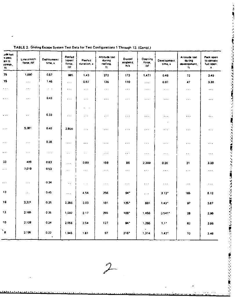
TABLE 2. Gliding Escape System Test Data for Test Configurations I Through 13. (Contd.)
-1 Pack Reeled Altitude lost Altitude lost Pack openan to Line ietch DIOment (open) Reefed during D0$rtef Opening DMIopment during to canopy"I'Me, fo force, lbf time, 5 force, duration, s reafing, irgleer, force, time, 6 dowelopment, full opn.force. , hls Ibf tms ~ eomn, fl pn-t Ibf ft __ __ ___ ft I
75 1,690 0,57 985 1.43 272 173 1,477 0.49 72 2.49
15 ... 1.46 ••. 0.87 136 110 ... 0.97 47 3.30
0.43 I
0.33 .,* ,
5.081 0.40 2,800 ... ....,..
II
1 0.38 ...
33 409 0.83 ... 0.80 159 86 2,309 0.20 21 33
7,019 0.53 I...
.0.34
13 .. 0.45 .. . 4-54 256 94 . 3.13'. 18b 8.12 '19 2,321 0.25 2,286 2.03 191 125- 8a1 1.43'. 97 3.87
13 2,165 0.25 '1,092 2.17 255 log. 1,456 Z,.54 1 26 2.96II
10 ,129 0.240 2,8056 25 2 4 ,6 . 238
a 2,196 0.22 1,946 1.81 97 216' 1,314 1,43'. 70 3.46 -4
I .
.~A P A . _,PA -_ . 0-P -
-*.1
TABLE 2a. AGES Test Dat.
Test Test GrOss Launch airspeed Altitude Line stretch Reefed openDate, 83 configuration weight,
number Ib KIAS KTAS Ft/s Time, s Force, Ibf Time, s Force, i
14 Feb 13 3400-2 300 200 225 380 7500 0.492 1981 0.767 568
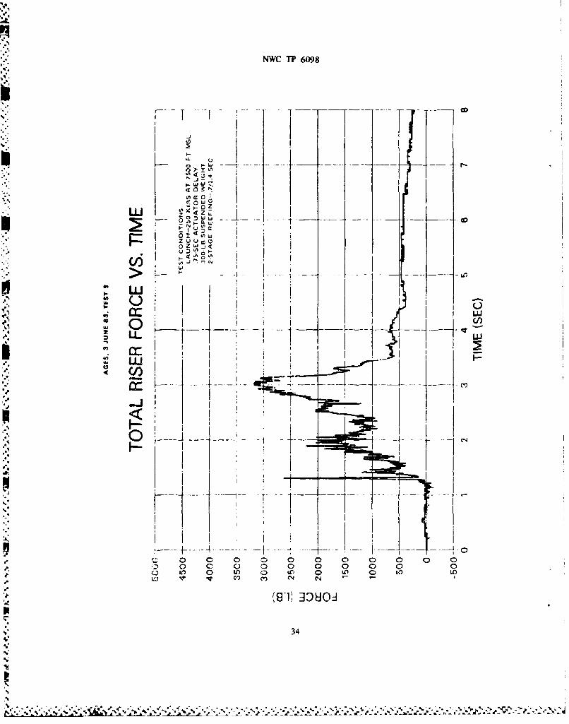
3 Jun 13 3400-3 300 250 278 470 7500 0.3003 1542 0,857 1609
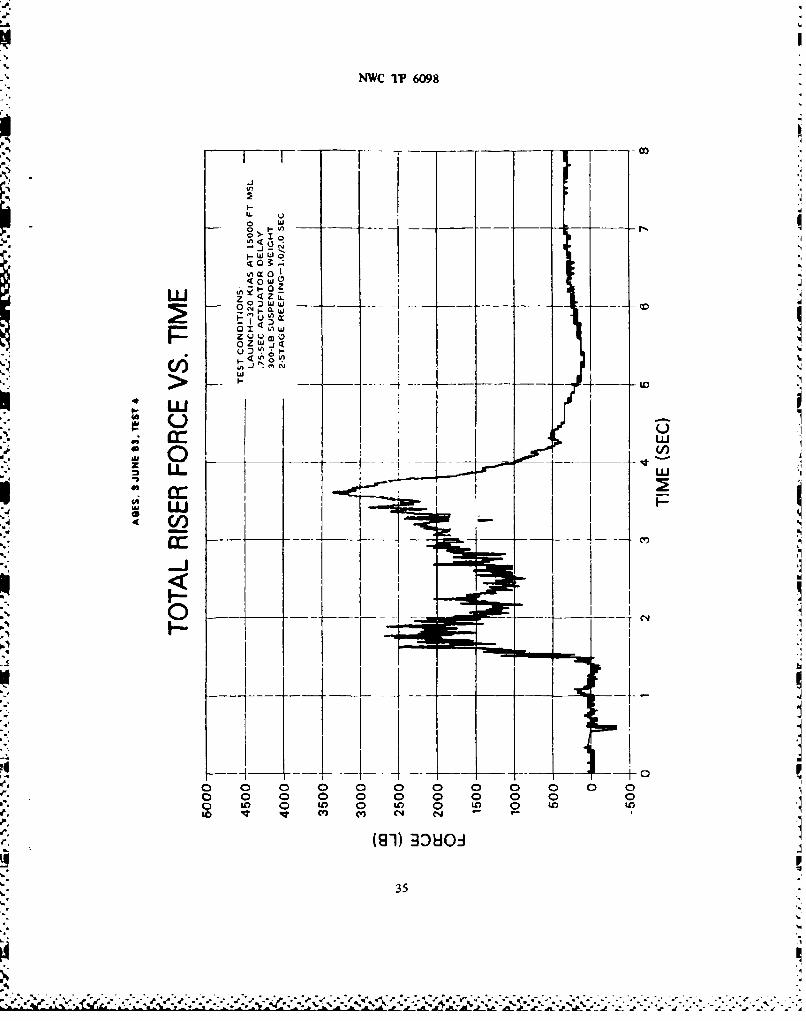
3 Jun 11 3400-4 300 320 401 680 15000 0.350 153Z 0.513 2011
8 Jun 13 3400-5 300 250 278 470 7500 0250 482 0.7240 1595
8 Jun 13 3400-6 300 300 335 565 7500 0297 1194 0.616 2181
10 Jun 13 3400-7 300 85 89 150 5000 1.190 2267 N/A N/A
pI
j,/A
NWC TP 6098
TABLE 2a. AGES Test Data.
Line Stretch Reefed open D-sreef Maximum Time to Remarks
force, lbf full openIme, s Force, Ibf Time, s Force. fbf Time, s Force, lbf
!3.492 1981 0.767 568 2.901 159 3138 4.342 1-stuge reefing; 2.0-s total time
3.3003 1542 0.857 1609 1.6013 1862 3138 2.14 2-stage reefing; 0.7/1.4-s delay
3.350 1533 0.513 2011 1.968 1969 3274 2.6886 2-stage reefing: 1.0/2.0-s delay
.250 482 0.7240 1595 2.083 1926 1926 4.400 1-stage reefing; 2.0-z total time
ý3.297 1194 0.616 2181 1.716 2510 3701 2.12 2-stage reefing; 0.7/1.4-s delay
."1.190 2267 N/A NiA N/A N/A 1928 1.573 Slider reefing only
I2
J". ". T ; G ;•-#2. " . -
DRAFT
NWC TP 6098
Appendix A
OPERATIONAL REQUIREMENT (OR)
HIGH-GLIDE-RATIO PARACHUTE
FOR
EJECTION SEAT AIRCRAFT
1. OPER•ATIONAL NZED
a. Threat.
(1) Capture and subsequent incarceration and/or deathof combat aircrews subsequent to ejcction over hostile territory.
(2) Iligh risk of personal injury duo Lo parachute landingin unfavorable terrain.
. CO'crational Problem. Prescnt parachute systems installedin ejection seats of tactical jet aircraft do not provide formaximum evasion capability after ejection over hostile territory.Although aircrew systems change No. 383 (Parachute Four LineRelease M4odification) does provide limited maneuverability andforward airspeed (3-4 knots) when incorporated into the present,standard navy parachute, its ability to prevent serious injuryand enhance evasion mus, Le considered Minimal when compared tothe potential of parachutes incorporating "present-day" highlift design technology.
II. OPERATIONAL CONCEPT. High-Glide-Ratio parachutes would beused primarily by ejectees to maneuver themselves (luring parachutedescent to avoid unfavorable landing terrain (t-rcos, large rocks,rivers, etc.) and/or avoid the threat of capture by hostileground forces. Aircrew systems change No. 383 is consideredto be ar appropriate interim solution, but does not fulfill per-formance goals as presented in Section III.a. Logistics andtraining support requirements have not been determined, nor arethey considered appropriate for determination at the originator'slevel. Nevertheless, support in the form of changes to applicabledirectives concerning parachute systems (e.g., NAVAIR 13-1-6.2";;anual) , training of navy survival equipmentmen (PR's) in main-tenance of acquired systems and training of potential users is ofp~ramount .Importance.
29
," %* .. ',%,i." '''',,:'v',' :' ,."* ,'' ' "-"" -'- '" " "" - " "* -'" "- "" "-" """.* "' P " ". "'". ' "
J-¢
DRAFT
NWC TP 6098
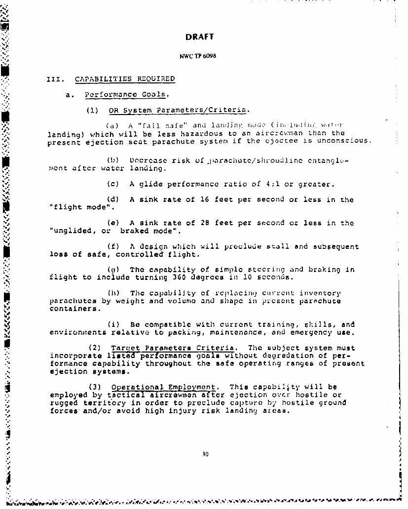
Ill. CAPABILITIES REQUIRED
a. Performance Goals.
(1) OR System Parameters/Criteria.
(a) A "fail safe" and lanrdini. modJ (In,r lu,•JnI wt,.*'
landing) which will be less hazardous to an aircrc;.,'nan than thepresent ejection seat parachute system if the ejectee is unconscious.
(b) Dcecrcasc risk of .parachutc/shrou21ine cntangl(--
sent after water landing.
(c) A glide performance ratio of 4:1 or greater.
(d) A sink rate of 16 feet per second or less in the"flight mode".
(e) A sink rate of 28 feet per second or less in the"unglided, or braked mode".
(f) A dcsign which will preclude stall and subsequent
loss of safe, controlled flight.
(9) The cnpability of simple stccring and braking inflight to include turning 360 degrccs in 10 seconds.
(h) Thc capability of rcplacingj curLeCnt inventoryparachutes by weight and volunie and shapc in p;:csent parachutecontainers.
(i) BO compatible with current training, shills, andenvironments relative to packing, maintenance, and emergency use.
(2) Targett Parameters Criteria. The subject system mustincorporate listed performance goals without degredation of per-formance capability throughout the safe operating ranges of presentejection systems.
(3) Operational Employment. This capabil2ty will beemployed by tactical aircrewinon after ejection ovcr hostile orrugged territory in order to preclude capture bý, hostile groundforces and/or avoid high injury risk landing aicas.
9I
.10j-'
" P.0 O %
DRAFT
NWC TP 6098
b. Manpower and Personnel Considerations
(1) An increase in manpower requirements is not projected.However, training of maintenance personnel concerning a newlyacquired system will be required.
c. Reliability and Maintainability.
(1) Maximum rcliability and maintainability with minimaltrade-off in operational capability is required for enhancement ofaircrcw survivability.
IV. QUANT1TIES AND COST OBJECTIVLS
a. A sufficient quantity of high-glide-ratio parachutes torctrofit all U. S. Navy tactical, ejoction seat aircraft (plussufficient spares) is required. A realistic estirmation of totalprogram cost can not be determined at the originator's level.
i.Ati sooni as fc.s.iblu.
VI. r1'0I 0O;1 /CSTE I r.ATrD FUNDING
a. To be determined by higher authority.
VII. O:-GOING/r£ELATrD EFFORTS
a. Civilian/Military sport parachuting organizations only,
at present.
VIII. PRINCIPLE UIARFARE AREA
a. Tu be detuovmined by hil)hcr auLhuriL'y.
d IX. UCtLA'f= 1I'AKFAI;Z AIREA
a. To be determined by higher" authority.
• . -"I. - ' ' •' "• "" °• ° ' """" ' " "•" "' i"" ' ': """ "°':, " *• • . , a , * a I , 4 &..b.- "q4 9 '%~.,~ ~ •,# ~ l d , q. ''.. %- -•'* * 6 €
NWC 1P 6098
4e Appendix B
SAMPLE LOAD TRACESAGES CONFIGURATION 13
TEST DATES 3 Jun. 8 Jun, 10 Jun 1983
.13
4V
NWC 1? 6098
7i T 4 1 11
In w
v ccMU D
LLIUI
C, F-Lu---- - - -
0
LL.
14 LL)
L- -
DUOJ 00
34
LA
NWC 1P 6098
0 I:
"N I- a
t ,Q
ol0 Wh
o Zwiz~
>>I
(ouJicc -- oLUwL
CT 'tS'h
0 00000 ZW0 0000 f i D O 0 Ot
(91 30801
35~
-Jr
NWC 1?~ 6098
-IT
I Cd.)
ww
-j- <aC.<I4
2 C/' 0o
z I-iDi!
-aj
o 0 0 C) '~ 0 0 0 0 0
36
. . . . . . .
m~. NWC TP 6098
a.o
I,-.
uj z CL
lii __ _
0 a IW
m
4A
-JJ
CC LJ
0 0 C0 C) 0 0 0 0 0 0 0 00 0 0 Q 0 0 0 0 0 0
O ~O Q r) 0 L Ul)LC
191) 3ZUOJ
37
NWC
NW6T 69
fw l
IuIicc)>-j .-- I"
I I I -n
i( 4 o
INITIAL DISTRIBUTION ;4~~ ,~~
-0 ,4 '
8 Naval Air Systems CommandAIR-00D34 (2)AIR-310H (2)AIR-531 (4)
1 Chief of Naval Operations (OP4O0C) AI Chief of Naval Material (MAT-08D4)A
4ain CopJeeo m ntad E uain Co m n. Q atc2 Naval Sea Systems Command (SEA-99612)
ICo,.-mander in Chief, U.S. Pacific Fleet (Code 325)
I Commander, Third Fleet. Pearl HarborI Commander, Seventh Fleet, San Francisco .
4 Naval Air Development Center, Warminster (Code 8032)1 Naval Air Technical Training Center, Lakehurst1 N4aval Air Test Center, Patuxent River (Code SY.70)3 Naval Ship Weapon Systems Engineering Station, Port Hueneme
Coe 5711, Repository (2)Code 5712 (1)4
1 Pacific Missile Test Center, Point Mugu (Code 1131) KI Naval War College, Newport4 Army Research and Development Laboratories, Natick (DRDNA-UAS)2 Army Troop Support and Aviation Materiel Readiness Command, St. Louis ~'2 Aeronautical Systems Division, Wright Patterson Air Force Base W .
ASD/AEL (1) NASD/ENECA (1)
5Air Force Flight Test Center, Edwards Air Force Base (620th Test Croup. TEEF) rýI San Antonio Air Logistics Center, Kelly Air Force Base (SA-ALCIMMIRC) t-
12 Defense Technicail Information Ce'nter y1 Federal Aviation Administration (Standards Division, MIS 110)
'VA'
'A' r.4
4, N~>~.
BEST AVAILABLE COPY '
4s;A ýid