Embed Size (px)
Citation preview
Pergamon Energy Convers. Mgmt Vol. 39, No. 5/6, pp. 465-484, 1998
© 1997 Elsevier Science Ltd. All rights reserved Printed in Great Britain
PII: S0196-8904(96)00233-6 0196-8904/98 $19.00 + 0.00
SIMULATION A N D ANALYSIS OF A N A T U R A L L Y ASPIRATED IDI DIESEL ENGINE U N D E R TRANSIENT CONDITIONS COMPRISING THE EFFECT OF VARIOUS
D Y N A M I C A N D T H E R M O D Y N A M I C PARAMETERS
C. D. RAKOPOULOS and E. G. GIAKOUMIS Internal Combustion Engines Laboratory, Thermal Engineering Section, Mechanical Engineering
Department, National Technical University of Athens, 42 Patission Str., Athens 10682, Greece
(Received 11 June 1996)
Abstract--This work presents an analysis of the operation of an indirect injection, naturally aspirated, diesel engine under transient conditions resulting from a rapid increase in load. For this purpose, a single-zone thermodynamic model, following the filling and emptying modelling technique, is developed, which accounts for all basic parts of the thermodynamic engine operation; it also covers the dynamic simulation of the engine with special submodels to model the conservation of energy in the crankshaft, the inertia forces, the governor dynamics and the fuel pump characteristics. Unlike most previous models, the transient operation is not regarded as a series of steady state operating points, but care has been taken for the special characteristics of this unsteady operation. To this aim, analytical expressions were derived for the better simulation of combustion, mechanical friction and governor movement, which during the transient operation behave in a different way than at steady state. The model has been tested favourably (at steady state conditions) against results derived from detailed experimental work conducted at the authors' laboratory. A detailed parametric study is made, which includes the influence of a variety of dynamic and thermodynamic parameters on the transient response of the particular engine, as well as of a four-cylinder one with the same technical characteristics. For the latter case, a special multi-cylinder engine model has been developed, accounting in detail for the solution of the governing differential equations for every cylinder separately. Analytical diagrams for the effect of the operating parameters on the transient operation of the two typical properties of speed droop and recovery period are given, which quantify each parameter's contribution. Finally, the effect of a faulty fuel injection system on one cylinder of the four-cylinder engine is studied, providing important information about the engine's non-optumum operation. © 1997 Elsevier Science Ltd.
Transient performance Naturally aspirated diesel engine Speed droop Recovery period
Greek
NOMENCLATURE
D = Cylinder diameter (m) f = Governor clutch friction coefficient (Ns m -t)
fmep = Friction mean effective pressure (bar) G = Mass moment of inertia (kg m 2) k = Load torque constant (Nms) or Governor spring stiffness (N m -~) N = Engine speed (rpm) or Force (N) Q = Heat (J) r = Crank radius (m) T = Absolute temperature (K) or Torque (Nm) t = Time (s)
y = Servopiston position (m) z = Sensing element current position (m)
E = Angular acceleration (S -2) 2 = r/L ratio ~p = Crank angle (deg or rad) ~o = Angular velocity (s -~)
Subscripts
b = Burning e = Engine
fr = Friction
465
466 R A K O P O U L O S a n d G I A K O U M I S : A N A L Y S I S O F A S P I R A T E D IDI D I E S E L E N G I N E
in = Iner t ia 1 = H e a t loss o r L o a d
st = S t e a d y s ta te T = T a n g e n t i a l w = Wal l
Abbreviations
C A = C r a n k ang le (degrees) r p m = R e v o l u t i o n s pe r m i n u t e
INTRODUCTION
The transient response of naturally aspirated and turbocharged compression ignition engines forms a significant part of the engine's operation and is of critical importance due to the often non-optimum performance involved. For the diesel engines used for industrial applications, such as generators, rapid loading is required together with zero (final) speed droop for the base units, as well as rapid start-up for the stand-by ones. For other less critical (in terms of speed change) applications, such as ship propelling or pump driving, reliable governing is required as well as quick changes in the operating conditions. Rapid load changes can prove very demanding in terms of engine response and also in the reliability of fuel pumps and governors. Thus, a good interconnection and cooperation of all engine components during the transient response is vital for optimum performance.
Diesel engine simulation modelling has contributed enormously towards the aim of new evaluation and development. This holds for both single-zone [1-5] and multi-zone models [6-8].
Historically, the first simulation models analysing transient operation were published in the early seventies [9, 10]. These models (also known as quasi-linear ones) were based on the assumption that the transient operation behaves as a series of steady state operating points, and their use was limited since they depended heavily on experimental data.
From the mid-seventies until the early eighties, the most fundamental transient simulators were published, based now on a degree crank angle analysis, whether from the Imperial College researchers [11-14] or from the UMIST ones [15-17]. Watson and Marzouk reported one of the most advanced simulations at the time, combined with detailed experimental validation and parametric study on turbocharged diesel engines under both load and speed changes operating schedules [11-14]. They used a single-zone thermodynamic model following the filling and emptying modelling technique; the governor was modelled via a general type differential equation of second order, while each cylinder in a multi-cylinder engine was assumed to behave in the same way. In parallel, at the University of Manchester, the studies included, among others, two-stroke instationary engine operation [15] and methods for improving transient response [17].
The analysis of the transient performance of internal combustion engines goes on during recent years with works concentrating on spark ignition engines [18], on engine starting[19], on temperature fields [20, 21] and on pollutants emissions, either on a theoretical (degree crank angle) basis [22] or on an experimental basis [23] or, finally, in the form of transient cycles analysis [24]. Reliable study of the pollutants emissions during transient operation, on a degree crank angle basis, with the help of multi-zone models is an important objective, whose accomplishment is limited by the huge computational time required for the analysis of hundreds of cycles and also by the fact that the transient operation has not been yet fully analysed and diversified from the steady state one with complete account for its unsteady nature characteristics. Simulation constants are believed to behave differently during the transient response than under steady state, and care has to be taken for proper modelling.
The present work contributes to a better simulation of the transient operation by improving on the existing relations. It deals with the parametric study of one type of diesel engine, i.e. naturally aspirated, indirect injection, whose behaviour has been studied only experimentally [25], due to complete devotion to the direct injection, turbocharged diesel engine, which is the prime mover in most large unit applications. To this aim, detailed diagrams showing speed profiles together with the variation of various engine properties, with respect to the engine cycles for different thermodynamic and dynamic input parameters are presented. Moreover, the speed droop and the
RAKOPOULOS and GIAKOUMIS: ANALYSIS OF ASPIRATED IDI DIESEL ENGINE 467
recovery period of the engine's transient operation are given in diagrams with respect to each operating parameter, thus quantifying the weight and effect of each term.
Finally, the simulation is applied to a multi-cylinder engine, in order to study the important case, commonly encountered in practice, in which one cylinder of a four-cylinder engine suffers from a faulty fuel injection system, resulting in late injection. The specific case could not be studied with the "single-cylinder" assumption used by all other researchers to model the multi-cylinder engine. The response of the particular engine to specific load changes is studied with the help of a developed special multi-cylinder engine model, making clear how the "damaged" cylinder affects the overall transient response.
NOVEL FEATURES OF PRESENT SIMULATION
The simulation in this work includes the following innovative features, which are described in detail in the next sections:
(a) Detailed analysis of thermodynamic and dynamic differential equations, accounting for the continuously changing character of transient operation.
(b) Development of combustion and mechanical friction modelling, diversifying transient response from the steady state one.
(c) Detailed analysis on the simulation of the connecting rod, which is studied as a rigid body experiencing both rotating and reciprocating movement, allowing for the rod's angular acceleration and mass moment of inertia.
(d) A transient simulation model is coupled, for the first time, with a detailed and explicit mathematical model for the governor, which can prove very useful in the study of the effect of the governor type and its technical characteristics on transient behaviour.
(e) The simulation of the multi-cylinder engine response is considerably improved with the development of a special multi-cylinder engine model. Every cylinder's differential equations are solved individually, and consequently, a more accurate simulation of inlet and exhaust manifolds phenomena is achieved.
THERMODYNAMIC ANALYSIS
General description
In order to simulate the operation of the IDI diesel engine under consideration, a thermodynamic model is developed, the individual submodels of which are briefly described in the following subsections. There is a uniformity in space (mono-zone) of pressure, temperature and composition in the combustion chamber at each instant of time. The first law of thermodynamics is applied to the engine cylinder for both the main chamber and the prechamber and is solved together with the perfect gas state equation [5]. Internal energy is considered to be a function of temperature and equivalence ratio; relevant polynomial expressions proposed by Benson and Whitehouse [1] are used for each of the four species considered, i.e. 02, N2, CO2 and H20.
Fuel injection model
For evaluation of the amount of injected fuel per cycle, relations of the type Mtot =f(co, h) are used, derived from experimental work conducted at various steady state conditions. In the above expression, M,o, is the total mass of injected fuel per cycle, h represents the position of the fuel pump rack which depends upon the governor movement, and ~o is the engine angular velocity.
For simulation of the fuel injection rate (kg s-'), the expression proposed by Ferguson [2] is used:
Mtot -- ~OdF(n) \ " " - ~ d ] \ (1)
where In F(n) = (n - 0.5)In(n) - n + 0.5 ln(2rc) + 1/12n - 1/360n 3 + 1/1260n 5, with n = 3.6 for the present study. In the above expression, M,o, is the total mass of injected fuel per cycle and per cylinder, ~0s is the crank angle where injection begins and q~d is the duration of injection.
468 RAKOPOULOS and GIAKOUMIS: ANALYSIS OF ASPIRATED IDI DIESEL ENGINE
Combustion model
For study of the combustion process, the model proposed by Whitehouse and co-workers [1, 7, 26] is used for both the main chamber and the prechamber. In this model, the combustion process consists of two parts; a preparation limited combustion rate and a reaction limited combustion rate. The corresponding equations are:
~,T IA'I - - x i a r x ~ v P = ,,,,,1, ,-1.t'02 (kg/° CA) (2)
for the preparation rate, while for the reaction rate:
R = K~po~ e_~c,/T~( P _ R) dq~ (kg/° CA) (3)
Mi = S~,(dm~/dtp) dip is the total mass (kg) of injected fuel up to the time t (corresponding angle q~) considered, and (dm~/dq0 is the known injection rate from equation (1). M. = Mi - SP dtp is the total mass (kg) of unprepared fuel, act is the reduced activation energy (K), accounting also for the ignition delay, and po~ is the partial pressure of oxygen (bars) in the main chamber or the prechamber. The constant K~ in the preparation rate equation is based upon the Sauter mean diameter (SMD) of the fuel droplets [1], being expressed by a formula of the type K~ oc (1/SMD) 2. For the evaluation of SMD, the empirical expression proposed by Hiroyasu et al. [6] is used:
SMD = 25. l(Ap)-°"'p~ ''2 ~to131(pro) (4)
where Ap is the mean pressure drop across the nozzle in MPa, p, is the density of air at the time the injection starts in kg m -3 and V,o, is the amount of fuel delivered per cycle per cylinder in mm3/stroke.
In transient operation, as a result of an increase in load, very rapid and considerable changes in fuelling occur. These changes result in instantaneous misfunction of the fuel injection pump, thus leading to an incomplete combustion [25] which the steady state combustion modelling cannot predict. To this end, an expression has been developed which accounts for these discrepancies of the engine, correcting the constant K~ in the Whitehouse-Way model.
While at steady state operation, the expression K~ oc (1/SMD) 2 leads finally to an expression of the type Kl = (K~)0 (SMD0/SMD) 2, where (K00 and SMD0 are the values of K~ and SMD at nominal conditions. For the transient operation, the following relation is developed:
(SMD0)2{ { M t o , - Mi'ot'~ ] KI = (K,)o S - ~ 1--¢comb~ ('-Mt"~t)Z)f (5)
where the term Mto, represents the amount of injected fuel in the previous cycle and the denominator term (Mtot)max is used so that the coefficient Ccomb is made dimensionless. The above expression is used when Mtot > M[ot.
Heat transfer model
The model of Annand is used to simulate the heat loss to the cylinder walls for both the main chamber and the prechamber [27, 28]:
dQl ( a 2 b - -~ Re (Tw - - Tg) + c ( T ~ - 7**)] (6)
where F is the surface for heat exchange = 2(nD2/4)+ nDL, with L the instantaneous cylinder height in contact with the gas and D the cylinder diameter. A single "mean" wall temperature for the entire surface F is used constant in time. The Reynolds number Re = p?D/# is calculated with a characteristic speed equal to the mean piston speed ? = 2rN/30. The constants a, b and c are derived from calibration against experimental data.
RAKOPOULOS and GIAKOUMIS: ANALYSIS OF ASPIRATED IDI DIESEL ENGINE 469
Mechanical friction
For calculation of friction inside the cylinder, the formula of Millington and Hartless [29] is used:
(fmep)~t = 0.123CR + 4.774 × 10-' N (7)
where (fmep)st is the friction mean effective pressure (bars) at steady state conditions and CR is the compression ratio of the engine.
Rapid changes in loading cause great accelerations (positive or negative) of the engine which, according to Winterbone [16, 17], lead to considerable, though instantaneous, deflections of the crankshaft, resulting eventually in a direct increase of mechanical friction. The above phenomenon is simulated as follows (for the transient case):
=--) (8)
where e stands for the current angular acceleration (mean value over the engine cycle) and emax is the maximum angular acceleration (or deceleration) which is experienced due to a 0-100% load increase (or decrease) during one cycle. The coefficient cfr is dimensionless, and its significance in transient response, as will be shown in a next section, can be of considerable importance.
DYNAMIC ANALYSIS
Inertia forces and moments
All previous models consider the connecting rod as equivalent to two masses concentrated at its ends, one rotating with the crankpin and the other reciprocating with the piston assembly, having the same total mass and centre of gravity as the actual rod. In this work, a detailed study of the connecting rod is conducted, which is described in detail in Appendix A, for the evaluation of the reciprocating masses inertia force N ' r i n .
Engine dynamics
The instantaneous values for engine speed and angular acceleration are derived from the conservation of energy principle applied on the total system (engine-resistance). Its mathematical formulation [3, 11] is as follows, if G,o, represents the total system mass moment of inertia (engine, flywheel and resistance) in kg m2:
dco Te(tp, co) - T,(co) - Tfr : Gtot " ~ (9)
In the above expression, Te stands for the instantaneous value of engine torque, which is the sum of the gas and the inertia forces torque [30]:
T~(~o, co) = Log(~p)FpR, + NTin]r (10)
where pg(~p) is the instantaneous gas pressure (as recorded by the cylinder pressure transducer) and Fp is the piston cross section area = nD2/4.
T~(og), in equation (9), is the load (resistance) torque, which is usually expressed by a relation of the general form:
T~ = T+ kco S (11)
For a rigid load (road slope resistance, part of rolling resistance), T # 0 and k = 0. For a linear load (electric brake, generator), T = 0, k > 0 and s = 1. For a quadratic load (propeller, hydraulic dynamometer, aerodynamic resistance), T = 0, k > 0 and s = 2.
Tfr stands for the friction term, which is connected to the friction mean effective pressure through the constant during each cycle relation:
fmep Fpr (12) Tfr= 2re
470 RAKOPOULOS and GIAKOUM1S: ANALYSIS OF ASPIRATED IDI DIESEL ENGINE
Combining equations (9), (10), (11) and (12), and bearing in mind that dq3 = 09 dt = > d t = dq~/ o9, we get:
d_~_~ = a + / ~ +/~09s-, + Z + _~ (13) d~o 09 m 09 09
where:
a = a(~p) = 1/G~o,NTi.r is the inertia torque term; ~ = - 1 / G , o t T = 0 comes from the constant term of the load expression; ~2 = - k /G to t comes from the speed dependent term of the load expression; 7 = 7(~ o) = 1/GtotPs(~)FprR~ is the gas torque term; 6 = (1/Gtot)(fmep/2rc)Fpr is the friction torque term;
where ART+, and R~ are evaluated in Appendix A. Equation (13) describes the conservation of energy at the crankshaft in terms of angular velocity.
From this relation, it is then easy to find the angular acceleration e(tp) needed in equation (8), i.e.
d09 E(q~) = ~ = a + fl~ + fl2m * + V + 6 (14)
Governor dynamics
The (mechanical-hydraulic) governor, which is used in the present analysis, is an indirect acting unity feedback one, i.e. one with no ability for zero (final) speed droop. It consists of the flyweight-spring mechanism for the sensing of speed change and of the servomechanism for driving the fuel pump rack and, thus, correcting of fuelling.
For the sensing element mechanism, Newton's second law of motion states, neglecting the weight of the ballarms and clutch [31, 32]:
N. ~dz d2z Arc -- r~, -- ]-d-~ = msov ~-~
The above equation is transformed as follows, on a degree crank angle basis:
2 d2z . dz - - a g o v / g o v 0 9 - - m~o.,09 ~ +J09 ~ + (k bgovigov092)z = .2 2 k~ko (15)
where i~ov is the transmission ratio between crankshaft and governor axis (= 0.5), Arc is the flyweights centrifugal force = (a+ov + bgovZ)09 2, with a~ov, bgov functions of flyweights mass and sensing elements' geometrical characteristics, Nros, is the spring restoring force = k(~b0 + z), with k the spring stiffness, ~0 the prior spring strain (a measure of the governor setting or "throttle" position) and z the current deformation of it [resulting from the change in speed due to the load increase (or decrease)], f is the friction coefficient of the governor clutch and mgov is the mass of the clutch and the flyweights reduced on the clutch axis.
For the servomechanism, it holds, on a time basis [31, 32]:
dys O . . . . -d~ + B~oy~ = z~ (16)
where z~ = (z - Zo)/Zo, with z0 the initial governor sensing element position, found by application of equation (15) at steady state, y~ = (y - y o ) / y o , with y0 the initial servopiston position and y its current one, and D~,o, B~o are constants deriving from the servomechanism's dimensions and technical characteristics [32]. Between servopiston position y (0-15 mm) and fuel pump rack position h, a linear correlation exists.
MULTI-CYLINDER ENGINE OPERATION
For the proper simulation of the four-cylinder engine transient performance, a multi-cylinder engine model has been developed, i.e. one in which all the above mentioned differential and algebraic equations are solved separately for each cylinder.
RAKOPOULOS and GIAKOUMIS: ANALYSIS OF ASPIRATED IDI DIESEL ENGINE 471
At steady state operation, the performance of each cylinder is essentially the same, due to the steady state operation of the governor clutch and, therefore, of the fuel pump rack, resulting in the same amount of fuel injected per cycle. At transient operation, however, each cylinder experiences different fuellings during the same engine cycle (this means differentiation in gas torque from cylinder to cylinder) due to the continuous movement of the fuel pump rack, caused by the load change. These differentiations in fuelling result in significant differentiations in torque response (mainly during the early cycles, which nonetheless, affect the whole operation) and finally speed, as has been found by comparing the model results using both "multi-cylinder" and "single-cylinder" simulation philosophies.
It is noted here, that the case of multi-cylinder engine operation presented in this paper (i.e. faulty injection in one cylinder) could not at all be studied using "single-cylinder" assumptions modelling for the multi-cylinder engine, since no differentiation in cylinder operation is included in these "simpler" models. The present multi-cylinder engine modelling can also be used for the investigation of similar "faulty" operation at steady state conditions.
SOLUTION OF EQUATIONS
The calculation of all the above stated differential equations starts at the inlet valve closure position at the initial operating point (15% of engine full load at 1500 rpm), where an estimation of temperature, pressure and composition for all control volumes is made, and thereafter, a series of cycles (3-5) is performed up to the moment when the variables do not change from cycle to cycle, beyond a certain limit set for accuracy. After thermodynamic equilibrium is achieved, the simulation program proceeds with the transient subroutines now "turned on", but still without load change. This is made so that a dynamic equilibrium is also achieved at the initial operating conditions. This process requires one to two cycles.
After that, the load change is applied and the transient response evolves. The conservation of energy equation [equation (13)] is solved at each degree crank angle, providing the new values for angular velocity and acceleration. The new value of angular velocity is used for the thermodynamic calculations in the next step which, in turn, provide new values for engine torque, used by equation (13), and so on. At each degree crank.angle and after the new angular velocity has been found, equations (15) and (16) are solved, which provide new values for the sensing element and the servopiston positions z and y, respectively. From y, we find the corresponding fuel pump rack position h. At 38 ° CA before Top Dead Centre (static injection timing position) and with the current values for ~o, h, the fuel injection map subroutine is called for the evaluation of the amount of fuel injected. At the end of the cycle, mean values of all important properties are computed.
From the above analysis, it is obvious that the present simulation is a detailed one, accounting for changes at each degree CA, thus providing increased accuracy over previous models. The model is assumed to finally converge when the speed, governor positions and engine and load torques (mean values over the engine cycle) present no change in the current cycle compared to their values in the previous one beyond a certain limit of accuracy; this limit in the specific study was 0.02% for the speed and torques and 0.1% for the governor positions.
EXPERIMENTAL FACILITIES AND PROCEDURE
The experimental procedure, necessary for the calibration of the thermodynamic model under steady state operation, was conducted on a single-cylinder, Ricardo E-6, indirect injection diesel engine, fitted with a Comet MK.V swirl prechamber [7]. The basic engine design data are given in Table 1. The engine is coupled to a "Lawrence-Scott" NS Type, swinging field a.c. dynamometer for measuring the engine performance. Flush-mounted, water-cooled, piezoelectric "Kistler" transducers coupled to "Kistler" charge amplifiers were used for cylinder pressure diagrams acquisition. The pressure traces were recorded using a fast signal-sampling system of a laboratory data-processing IBM-compatible PC [33].
A detailed experimental investigation of .the engine processes was performed for various combinations of speeds and loads. The experimental results obtained were used to calibrate the

472 R A K O P O U L O S and GIAKOUM IS : ANALYSIS OF ASPIRATED IDI DIESEL ENGINE
thermodynamic model at steady state conditions, so that the appropriate Whitehouse-Way combustion and Annand heat transfer model constants were made possible to be estimated.
RESULTS AND DISCUSSION
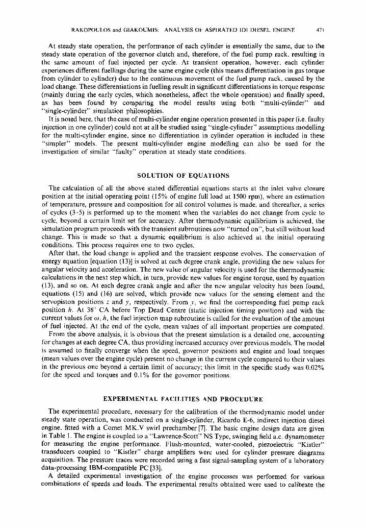
The sensitivity of the engine transient response, as a result of a rapid increase in load, to various dynamic and thermodynamic parameters and for a constant governor setting is presented in Figs 1-14. Two kinds of diagrams are mainly given. The first ones show the response of speed together with another, typical for each case, property, such as injected fuel or maximum cylinder pressures, and the second ones quantify the effect of each operating parameter on the speed droop and the recovery period. By the term speed droop, it is meant the (instantaneously) maximum deviation of speed from its initial value divided by the initial speed of 1500 rpm. By the term recovery period, it is meant the time period needed for the engine to reach 98% of its final speed. The term equilibrium period would possibly be more accurate here, since no restoration of speed is actually achieved.
For all cases analysed below, unless otherwise stated, the following assumptions are valid:
(a) the initial load is 15% of the engine's full load at the initial speed of 1500 rpm; (b) the engine full load (100%) at 1500 rpm is applied within 0.2 s; (c) the resistance type is linear, i.e. T = 0 and s = 1 in equation (11), resulting in T~ = kt~; (d) the total mass moment of inertia Gtot = 1.5 kg m2; (e) the coefficients Ccomb and err are at first zero (as their contribution requires experimental
validation).
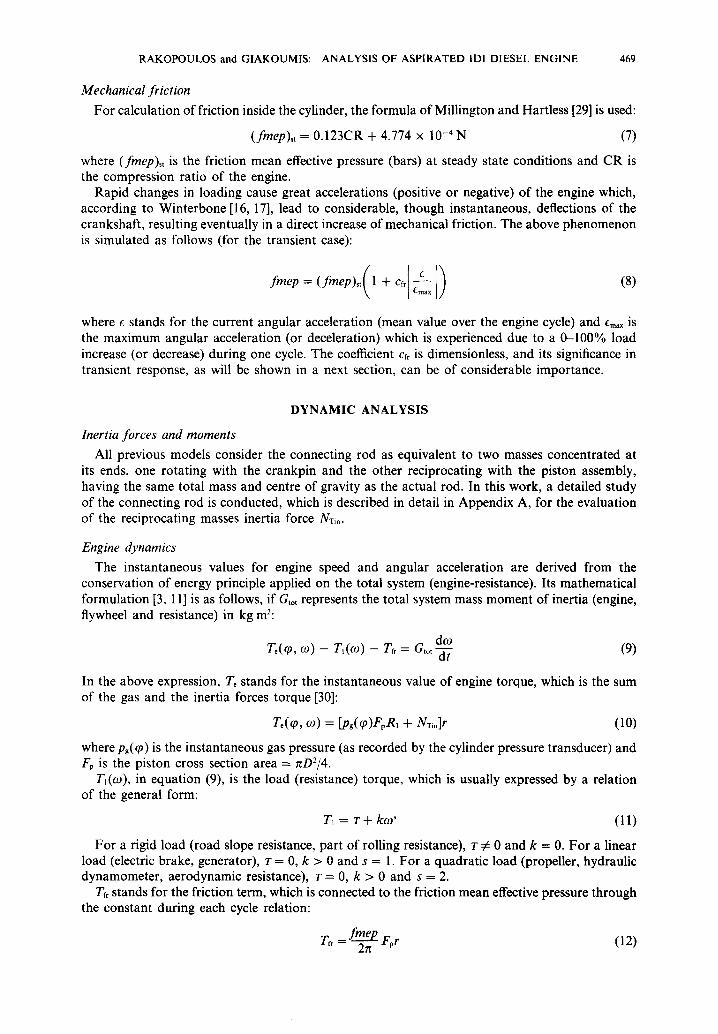
Figure 1 is a complete presentation of the predicted engine response to the nominal load change. Speed, injected fuel, engine and load torques, brake mean effective pressure (bmep), governor positions, angular acceleration, brake specific fuel consumption (bsfc) and maximum cylinder pressures are given with respect to the engine cycles (or the time). At the initial condition, the engine and load torques are equal. As soon as the new load is applied, the engine speed drops because the load torque becomes considerably greater than its engine counterpart. This leads to a movement of the governor sensing element which, in turn, shifts the servopiston (and consequently the fuel pump rack) towards a position of more fuelling. During the early cycles (where the energy deficit is greatest), the highest values for crankshaft deceleration occur. With the gradual increase in fuelling, the engine torque begins to rise, together with the cylinder pressures and brake mean effective pressure, and the brake specific fuel consumption improves itself (decreases) considerably. Two seconds after the application of the load change, the engine torque becomes equal to the load one, and at this point, the lowest engine speed is observed. Because of the type of load involved (linear), the drop in speed causes also a drop in load torque, resulting in quicker counterbalance between engine and load.
The final equilibrium is achieved after four seconds or fifty cycles. The final value for the amount of injected fuel per cycle is about 27 mgr, which corresponds to 90% of engine full load. Although the full engine load (100%) was applied at the initial speed of 1500 rpm, we note that the final condition corresponds to 90% load. This difference occurs because, as previously mentioned, the load torque decreases with the drop in speed, thus less power is needed from the engine for the
Table 1. Engine basic design data.
Type Bore Stroke Connecting rod length Compression ratio Prechamber volume Main chamber dead volume Intake valve opening Intake valve closure Exhaust valve opening Exhaust valve closure Static injection timing
Ricardo E-6 (Comet MK. V) research diesel engine
Single-cylinder, Four-stroke, IDI 76.2 mm I 11.2 m m 240.5 m m 21.29 11.5 cm 3 13.5 cm 3 8 ° CA before Top Dead Centre 36 ° CA after Bottom Dead Centre 43 ° CA before Bottom Dead Centre 7 ° CA after Top Dead Centre 38 ° CA before Top Dead Centre
RAKOPOULOS and GIAKOUMIS: ANALYSIS OF ASPIRATED IDI DIESEL ENGINE 473
7.5
,~ 5.0
2 . 5
0 . 0 ,,-., 30.0
~ , 2 0 . 0
~ I0 .0
[- ' 0 .0 30.0
@
o.o
r~
r~
C C
I0 .0 1500-
1450"
I400"
I350 o
e r c e n t ~,J 1..om/q/pe = ~ l . , . . r
LO¢I~ Ch, euru~e D~t'o,t'~o~:O.2 s e e
i i i i I i i ~ i I i i i i I i i i I
25 50 75 100~
NUMBER OF CYCLES
~ n I -; Chamber : ¢ : : : Preoh, o.mber
C C C C C
C
, , , , i , , , , i , , , , i , , , ~ I 0 - 0
2 5 50 7 5 1 O0
NUMBER OF CYCLES
• 100.0
"-90.0
• s o . , ~
70.0 1 0 0 0 ~_.
J= m¢
7 5 0 .~
8 0 0
- 2 5 0 ~-
0 - 1 . 0 ~ Z
o . s
NJ. -
- 1 . 0 ~ - 1 5 . 0 , '~
, o o
- r,~lO
- 5 . o o~_
'o b.'o b.'o o'o b'o 8.'o I i i i i i i i i i ! i i i ~ i i i i i i i i i i ~ i
0.0 . . . . . TIME (sec) TIME (sec)
Fig. 1. Predicted engine response to an increase in load.
equilibrium at a lower speed. If the resistance were rigid (cf. Fig. 4) or if an isochronous governor were used, irrespective of resistance type, the final load would be similar to that applied at the beginning. It is important also to note that a slight phase shift is observed when comparing speed and fuel profiles. This is because the governor (which is responsible for the amount of injected fuel) has an inertia of its own, which leads to a hysteresis in its movement (as described by equations (15) and (16)) compared to the speed. The fuel, engine torque, bmep and maximum pressures profiles present, as expected, the same phase development, as they all depend directly upon the fuel term.
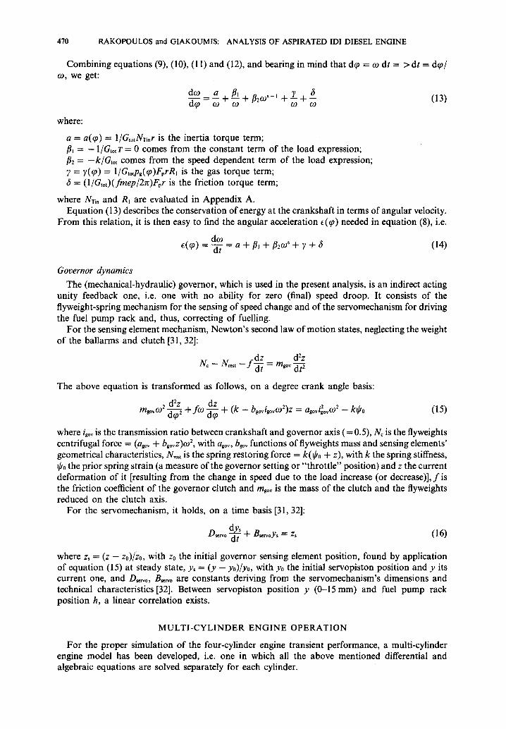
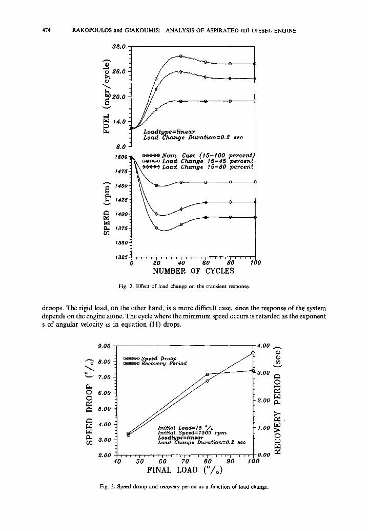
Figure 2 shows the variation of engine speed and injected fuel with respect to the engine cycles for three different cases of final load, i.e. 45, 80 and 100% of engine full load at 1500 rpm, while Fig. 3 concentrates on the effect of the applied load on the speed droop and the recovery period. As expected, the greater the applied load, the higher the deceleration of the crankshaft, leading to lower final speed and greater amounts of injected fuel at the final conditions. The minimum speed is observed at the same cycle (23-25th) for each case. The speed droop presents a considerable variation (i.e. 3-8.5%) according to each case, showing how important the intensity of the applied load is, while the recovery period shows no significant change for final loads greater than 70%.
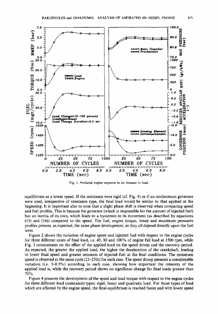
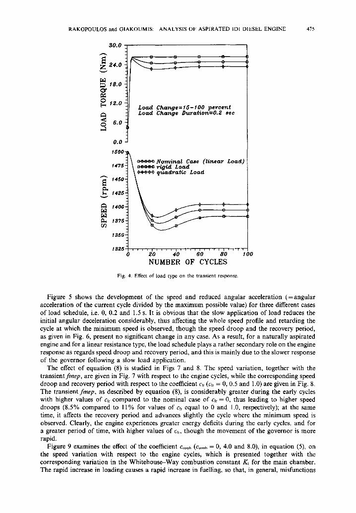
Figure 4 presents the development of the speed and load torque with respect to the engine cycles for three different load (resistance) types: rigid, linear and quadratic load. For those types of load which are affected by the engine speed, the final equilibrium is reached faster and with lower speed
474 RAKOPOULOS and GIAKOUMIS: ANALYSIS OF ASPIRATED IDI DIESEL ENGINE
32.0
0 26.0
o
M ~ 20.0
,.3 [z3 14.0
8 . 0
C
0
L o a d t y p e =l inear Load Change Dura t ion=0 .2 s e c
1 5 0 0 ~ cccc¢ Norrt. Case ( I 5 - 1 0 0 pe rcen t ~ c=-ca Load Change I 5 - 4 5 percent
1475~ ~ ¢ ¢ ~ Load Change 1 5 - 8 0 p e r c e n t
'-o t 1425- 0
~:~ 1400. r~ c ~x3
1375- o~
1350"
1 3 2 5 , , , ; l ~ , , , l l l l , i , f , l l , , , , 0 20 40 60 80 I O0
NUMBER OF CYCLES
Fig. 2. Effect of load change on the transient response.
droops. The rigid load, on the other hand, is a more difficult case, since the response of the system depends on the engine alone. The cycle where the minimum speed occurs is retarded as the exponent s of angular velocity co in equation (11) drops.
9.00 4.00
~'~ 8.00
C 7.00
6 . 0 0
5 . 0 0
4.00
3.00 CI3
2.00
Speed Droop /
J J Initi, at Load=t5 0/,, FI~ In i t ia l Speee~ 1500 rpm v Loadtype = lertear _
Load Change D~zration=0.2 see
I I I I I I I I I I I I I } I I I I I I I T I I I I I I I
40
¢,9
-3.00
2.00
1.00
o.oo ~ 50 60 70 80 90 100
F I N A L LOAD ( % )
Fig. 3. Speed droop and recovery period as a function of load change.
R A K O P O U L O S and GIAKOUM IS : ANALYSIS OF ASPIRATED IDI DIESEL E N G I N E 475
3 0 . 0
~ 24.0
18.o
o [~ 12.o
0 6 . 0 ,..3
0.0
1500"
cu
Load Char~ge=lS-lO0 percent Load Char~ge D~rat£o~=0.2 sec
f475"
1450"
1425 =
1400'
1375-
1350
1325 o
o o o o o Nom£rL¢l Case ( l inear
0
Load)
i i i i I i i i i I i i i i I I , i i I i i I i
20 40 60 80 1 O0 NUMBER OF CYCLES
Fig. 4. Effect of load type on the transient response.
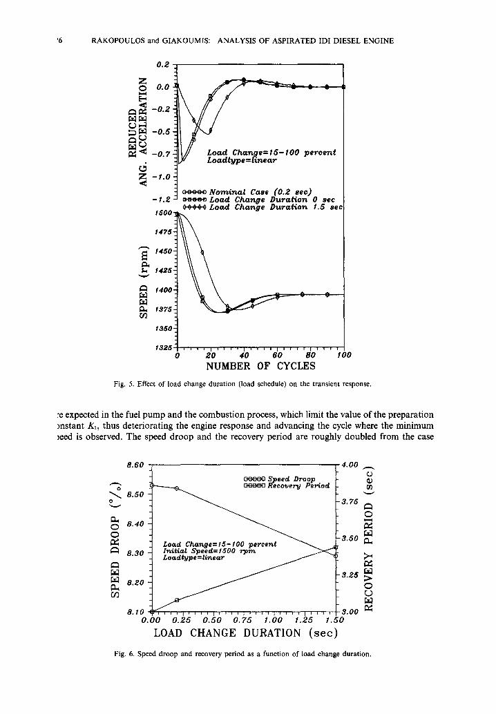
Figure 5 shows the development of the speed and reduced angular acceleration (=angular acceleration of the current cycle divided by the maximum possible value) for three different cases of load schedule, i.e. 0, 0.2 and 1.5 s. It is obvious that the slow application of load reduces the initial angular deceleration considerably, thus affecting the whole speed profile and retarding the cycle at which the minimum speed is observed, though the speed droop and the recovery period, as given in Fig. 6, present no significant change in any case. As a result, for a naturally aspirated engine and for a linear resistance type, the load schedule plays a rather secondary role on the engine response as regards speed droop and recovery period, and this is mainly due to the slower response of the governor following a slow load application.
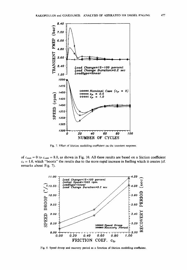
The effect of equation (8) is studied in Figs 7 and 8. The speed variation, together with the transientfmep, are given in Fig. 7 with respect to the engine cycles, while the corresponding speed droop and recovery period with respect to the coefficient Crr (cfr = 0, 0.5 and 1.0) are given in Fig. 8. The transient fmep, as described by equation (8), is considerably greater during the early cycles with higher values of cfr compared to the nominal case of cf, = 0, thus leading to higher speed droops (8.5% compared to 11% for values of crr equal to 0 and 1.0, respectively); at the same time, it affects the recovery period and advances slightly the cycle where the minimum speed is observed. Clearly, the engine experiences greater energy deficits during the early cycles, and for a greater period of time, with higher values of Crr, though the movement of the governor is more rapid.
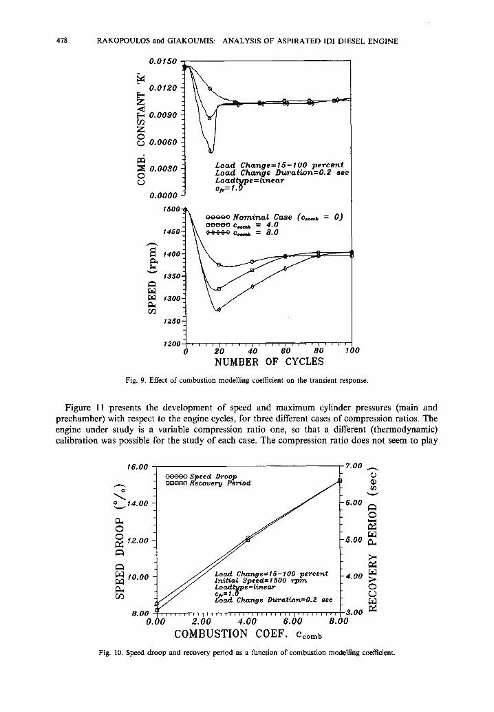
Figure 9 examines the effect of the coefficient Ccomb (Ccom~ = 0, 4.0 and 8.0), in equation (5), on the speed variation with respect to the engine cycles, which is presented together with the corresponding variation in the Whitehouse-Way combustion constant Kt for the main chamber. The rapid increase in loading causes a rapid increase in fuelling, so that, in general, misfunctions
'6 RAKOPOULOS and GIAKOUMIS: ANALYSIS OF ASPIRATED IDI DIESEL ENGINE
0 . 2
Z o
d Z
O3
0.0
-0.2
-0.5
-0.7
-1.0
-1.2 ! ,5003.
1475 Z
1450
1425-
1400
1375 £
13501 18z5 I
0
~~ L o azltbrp e =/,/,ne,,tr
c c c . : . ~ Nomina t Case (0.2 see) c==== L o a d Change D t c r o ~ o n 0 s e c ¢ ,¢ ,~ ¢ ¢ L o a d C h a n g e D t c r a ~ o ~ 1 .5 s e e
, i i I i i i v I i i i i I I I I I [ I I I I
2 0 40 60 80 100 NUMBER OF CYCLES
Fig. 5. Effect of load change duration (load schedule) on the transient response.
:e expected in the fuel pump and the combustion process, which limit the value of the preparation instant K~, thus deteriorating the engine response and advancing the cycle where the minimum ~eed is observed. The speed droop and the recovery period are roughly doubled from the case
0
o 0
8.60 4.00 Speed Droop
r ~ Reeo~e~,td Pe~riod
8.508.40 ~ J -3.50"3"75
8.30 17t£t~al Speed=lSO0 rIarr¢ ~
8.gO ~ "3.25
8.10 . . . . . ~ . . . . = . . . . ~ . . . . ~ . . . . I . . . . 3.00 0.00 0.25 0.50 0.75 1.00 1.25 1.50
LOAD CHANGE DURATION (see)
O
0t)
O
0 0
Fig. 6. Speed droop and recovery period as a function of load change duration.
RAKOPOULOS and GIAKOUMIS: ANALYSIS OF ASPIRATED IDI DIESEL ENGINE 477
8 . 4 0
e~ 7.20
6.00
ra~ 4 . 8 0 [.-,
Z 3 . 6 0
03 Z , 2 . 4 0
1 . 2 0
1 5 0 0 .
03
v v v v w w
L o a d C h ~ n g e = 1 5 - t O 0 p e r c e n t L o a d C h ~ g e D u r a t i o n = 0 . 2 see Loo~t~lpe=linear
1475"
1450"
1425"
1400 ~
I 3 7 5 "
1 3 5 0 i
13z5-
1300 0
c : : : o N o m i n ¢ l C a s e ( = O) c , = o:5 i
i i I ' ' ' ' I I , i , ! i i , I I ' I ~ ,
2 0 4 0 6 0 8 0 I O0
NUMBER OF CYCLES
Fig. 7. Effect of friction modelling coefficient on the transient response.
of Ccomb ~- 0 to Ccomb = 8.0, as shown in Fig. 10. All these results are based on a friction coefficient Crr = 1.0, which " b o o s t s " the results due to the more rapid increase in fuelling which it creates (cf. remarks abou t Fig. 7).
0
1 1 . 0 0
1 0 . 5 0
1 0 . 0 0
0 o 9.50
C13
9.00
8 . 5 0
8 . 0 0 0.00
• . 4 . 2 0 Lo=d C l ~ n g e = 1 5 - 1 0 0 p e r o e n t / ) Initi, at S p e e d = l S O 0 r ' F m / L o a d t y p e = l i n e a r J ) '4 O0 Lo¢cd Change Duration=0.2 see / / •
/ /
~ ~ 3.40
E 3 20
f ~--=~ R-eeo.ue.r'g Period L c c c ~ p e e d Droo_~ _ t- "
w , , , I ' ~ ' ' t ~ ' ' ~ I ' ' ' ' I ' ' ' ' | I 3 . 0 0 0.20 0.40 0.60 0 .80
F R I C T I O N C O E F . e r r
1.00
CJ ¢D
O
;> O
Fig. 8. Speed droop and recovery period as a function of friction modelling coefficient.
478 RAKOPOULOS and GIAKOUMIS: ANALYSIS OF ASPIRATED IDI DIESEL ENGINE
E-,
.,¢ [.,
Z 0
0
O.Of50
0.0120 i
- v . - v - w
0 . 0 0 9 0
O. 0 0 6 0
0.0030 Load Cha~ge= 15- I00 percent L o a d C h a n g e D t t r a t i o n = 0 . 2 see L o a d t y p e =linear o~.= 1 .0
0.0000 ~5oo~
"1 ~ c c c : o NoTrt inal Case (e=,,,~ = O) :l ~ c:.:.:.-'-, e , ~ = 4.0
1450~ \ \ ¢,~¢,~ e~,~ = 8.0
1350
~ 13oo. ~ , / rd~
1280.
1200 0
i i ~ i = i i i i i i i % '4b' go' d0' ',oo NUMBER OF CYCLES
Fig. 9. Effect of combustion modelling coefficient on the transient response.
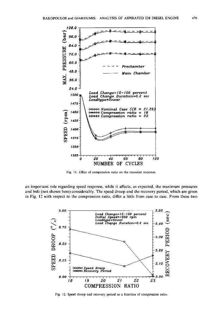
Figure 11 presents the development of speed and maximum cylinder pressures (main and prechamber) with respect to the engine cycles, for three different cases of compression ratios. The engine under study is a variable compression ratio one, so that a different (thermodynamic) calibration was possible for the study of each case. The compression ratio does not seem to play
16.00 , 7 .00 I
~CCO Speed Droop c===~ Recovery P e ~ o d
f . . . . . 5.00
£~o~ Ch ~e=lS- I00 percent a ~n / / /n~t~=e Spe~ed=~O0 r p m . . . .
/ / Loadtltpe = l£near / / c_~= (. o . . . . .
f o a d C ~ e D'urott~ort=0.2 see 8 .00 ' ~ l . . . . . . . , , I . . . . . . . . 3 .00
0 . 0 0 2.00 4 . 0 0 6 . 0 0 8 . 0 0
C O M B U S T I O N C O E F . e~or~b
°..._..14.00
0 O l a . o o
1o.oo
U3
@
o
o
Fig. 10. Speed droop and recovery period as a function of combustion modelling coefficient.
I 0 8 . 0
¢~ 9 6 . 0
8 4 . 0
72 .0 r.D r13
6 0 . 0
4 8 . 0
• ' ~ 3 8 . 0
2 4 . 0
15 O0 -
1 4 7 5 -
¢~
Oq
f450.
1 4 2 5 2
0
1400"
I3752
1350
1 3 2 5 0
~-~---~--i ~ - a . . - ~ - ~ _ _ - O _ _ _
P r e c h a m b e r
M a i n C h a m b e r
L o a d C h a n g e = 1 5 - 1 0 0 p e r c e n t Loo.d C h a n g e D u r a t i o n = 0 . 2 see L o a d t y p e ffi l i n e a r
N o m i n a l Case (CR = 2 1 . 2 9 C o m p r e s ~ o n taboo = 18 C o m p r e s s i o n r a t i o = 23
i i ~ , I , , i i I i i i i I i i , i I ~ i i i
2 0 4 0 60 8 0 1 O0
NUMBER OF CYCLES
Fig. 11. Effect of compression ratio on the transient response.
an i m p o r t a n t role regard ing speed response, while it affects, as expected, the m a x i m u m pressures and bsfc (not shown here) cons iderably . The speed d r o o p and the recovery per iod, which are given in Fig. 12 with respect to the compress ion rat io , differ a little f rom case to case. F r o m these two
0 0
CI3
8.25
9 . 0 0 3 . 5 0
8 .75
8 .50
8 .00
cc. .~=~ R e c o v e r y P~r~od
L o a d C h a w , g e = 1 5 - 1 0 0 percent I n i ~ a l S p e e d = 1 5 0 0 rprn Loadtbrpe=linear Load C h ~ g e Duration=0.2 s e e
RAKOPOULOS and G1AKOUMIS: ANALYSIS OF ASPIRATED IDI DIESEL ENGINE 479
" 3 . 4 0
3 . 3 0
3 . 2 0
3 . 1 0
' ~ ' ' I ' ~ E , I ' ~ ' ' I ~ ' ' ~ I ' ' ' ~ 3.00 18 1 9 2 0 2 1 2 2 2 3
COMPRESSION RATIO
O
O I,,,,,d
>
0
Fig. 12. Speed droop and recovery period as a function of compression ratio.
480 RAKOPOULOS and GIAKOUMIS: ANALYSIS OF ASPIRATED IDI DIESEL ENGINE
figures, it becomes obvious that the choice of the optimum compression ratio remains a matter of the steady state, rather than transient, response optimization procedure.
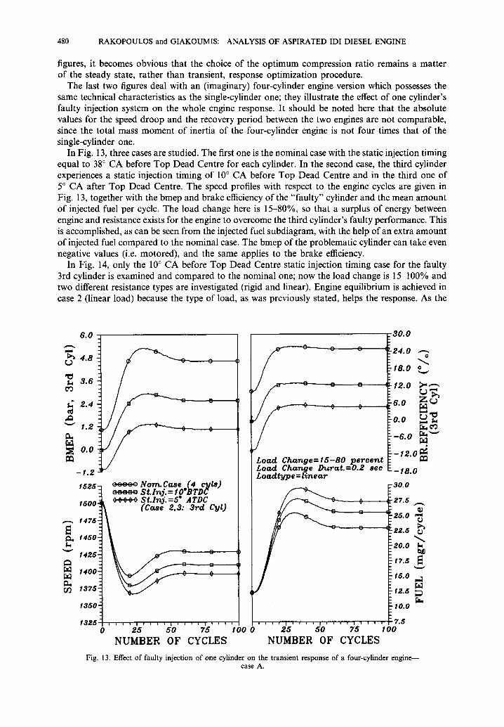
The last two figures deal with an (imaginary) four-cylinder engine version which possesses the same technical characteristics as the single-cylinder one; they illustrate the effect of one cylinder's faulty injection system on the whole engine response. It should be noted here that the absolute values for the speed droop and the recovery period between the two engines are not comparable, since the total mass moment of inertia of the four-cylinder engine is not four times that of the single-cylinder one.
In Fig. 13, three cases are studied. The first one is the nominal case with the static injection timing equal to 38 ° CA before Top Dead Centre for each cylinder. In the second case, the third cylinder experiences a static injection timing of 10 ° CA before Top Dead Centre and in the third one of 5 ° CA after Top Dead Centre. The speed profiles with respect to the engine cycles are given in Fig. 13, together with the bmep and brake efficiency of the "faulty" cylinder and the mean amount of injected fuel per cycle. The load change here is 15-80%, so that a surplus of energy between engine and resistance exists for the engine to overcome the third cylinder's faulty performance. This is accomplished, as can be seen from the injected fuel subdiagram, with the help of an extra amount of injected fuel compared to the nominal case. The bmep of the problematic cylinder can take even negative values (i.e. motored), and the same applies to the brake efficiency.
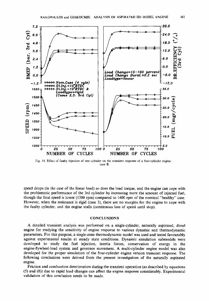
In Fig. 14, only the 10 ° CA before Top Dead Centre static injection timing case for the faulty 3rd cylinder is examined and compared to the nominal one; now the load change is 15-100% and two different resistance types are investigated (rigid and linear). Engine equilibrium is achieved in case 2 (linear load) because the type of load, as was previously stated, helps the response. As the
6 . 0
>~ 4.8
3.6 Cq
" ~ 1.2 D.,
=~ o.o
- I . 2
1525-
1500.
r, f j
1475"
1450"
I4z6-
1400,
1375!
tsso-
1325 0
/ / /
C
c c c : o NormCoae (4 c~ila) : : : : o St . l n j . = IO*BTDd ~¢¢¢0 S t . l n j . = 5 ATDC .
(Co~e 2 ,3 : 3 r d C~lt)
C
0 -_
C C
0
Load Change=15 -BO p e r c e n t Load Char~ge D~ra t .=0 .2 see Loo, d t~pe = G n e a r
C
C
i i i i I i i i i
I 0 0 0 2 5 5 0
NUMBER
i i i I I r i i i I i i i i I i i I i
25 50 75 NUMBER OF CYCLES
~ 3 0 . 0
2 4 . 0 O
• 18 .0 o v
I 2 . 0 ~ "
6.O ~
~0.0
I - 6 . 0
- 1 2 . 0
~ - I 8 . 0
~ 30.0
~_27.5
_25.0
~_ 22.5
20.0
f7.5
15.0
t2 .5
10.0
I , , , , I , , , , 7.6 75 1 O0
OF CYCLES
Fig. 13. Effect of faulty injection of one cylinder on the transient response of a four-cylinder engine-- case A.
~r.i eO
0) o o
r~
R A K O P O U L O S and G I A K O U M I S : ANALYSIS OF ASPIRATED IDI DIESEL ENGINE 481
?.2
>~ 6.0
,~ 4.8
3 . 6
2 . 4
I ~ 1 .2
o.o
- 1 . 2
1550-
1500.
1450"
,4oo: v
(i~ 1350"
1300 S O~
C C
I 250 .
1200 o
c e e c o Norr~.Co~e _(4 ellis) = = = = ' ~ S t . I ~ . = IO'BTDC ¢~,~,~ St.Ir~j.=IO°BTDC &
£oadtTjpe:rig~d (Co~se# 2,3: 3rd CaJO
o o o
9 C C C
Loo~I. C i ~ g e = I 5 - 1 0 0 p e r c e n t Loa~ C h ~ g e D ~ r a t . = 0 . 2 see Loadt,d~pe=Hnear
30 .0
c c
2 4 . 0
t8.0
I2.0
6.0
~_0.0
- 6 . 0
- 1 2 . 0
- 3 5 . 0
L 30.O
¢3
£ 5 . 0 0
2 0 . 0 t:~
~- 15.0
lO.O f.~
] l i I I I i I ' I , I ' ' I i I , ~ I , , , I i , , i I ' i l i I ' i I i ~ . 0
25 50 75 1 O0 0 25 50 75 I O0
NUMBER OF CYCLES NUMBER OF CYCLES
Fig. 14. Effect of faulty injection of one cylinder on the transient response of a four-cylinder engine- - case B.
[.ra
speed drops (in the case of the linear load) so does the load torque, and the engine can cope with the problematic performance of the 3rd cylinder by increasing more the amount of injected fuel, though the final speed is lower (1380 rpm) compared to 1400 rpm of the nominal "healthy" case. However, when the resistance is rigid (case 3), there are no margins for the engine to cope with the faulty cylinder, and the engine stalls (continuous loss of speed until stop).
CONCLUSIONS
A detailed transient analysis was performed on a single-cylinder, naturally aspirated, diesel engine for studying the sensitivity of engine response to various dynamic and thermodynamic parameters. For this purpose, a single-zone thermodynamic model was used and tested favourably against experimental results at steady state conditions. Dynamic simulation submodels were developed to study the fuel injection, inertia forces, conservation of energy in the engine-flywheel-load system and governor movement. A multi-cylinder engine model was also developed for the proper simulation of the four-cylinder engine version transient response. The following conclusions were derived from the present investigation of the naturally aspirated engine.
Friction and combustion deterioration during the transient operation (as described by equations (5) and (8)) due to rapid load changes can affect the engine response considerably. Experimental validation of this conclusion needs to be made.
482 RAKOPOULOS and GIAKOUMIS: ANALYSIS OF ASPIRATED IDI DIESEL ENGINE
The intensity of the applied load affects seriously both the speed droop and the recovery period. The type of load involved (rigid, linear, quadratic) plays a significant role, as loads which depend
on speed vary favourably during the operation according to o9, thus contributing to quicker equilibrium.
The load schedule affects the speed profile but not the speed droop and the recovery period significantly.
The compression ratio plays a secondary role affecting thermodynamic (e.g. maximum cylinder pressures) but not dynamic (e.g. speed) properties.
It is a matter of final load applied and type of load involved for an engine with one problematic cylinder to cope successfully (though with greater speed droop) with a specific load change.
All in all, the speed droop improves with speed dependent load types and low values of applied load, while it stays unaffected by the load schedule and the compression ratio.
The recovery period deteriorates with big applied loads, rigid type of resistances and faulty operation of at least one cylinder in a multi-cylinder engine, while it is not affected remarkably by the compression ratio and the load schedule.
REFERENCES
1. Benson, R. S. and Whitehouse, N. D., Internal Combustion Engines. Pergamon Press, Oxford, 1979. 2. Ferguson, C. R., Internal Combustion Engines. Wiley, New York, 1986. 3. Heywood, J. B., Internal Combustion Engine Fundamentals. McGraw-Hill, New York, 1988. 4. Rakopoulos, C. D., Energy Conversion and Management, 1991, 31, 447. 5. Rakopoulos, C. D. and Giakoumis, E. G., Energy Conversion and Management, 1997, 38, 347. 6. Hiroyasu, H., Kadota, T. and Arai, M., Bulletin of the JSME, 1983, 26, no. 214. 7. Kouremenos, D. A., Rakopoulos, C. D. and Hountalas, D. T., Transactions of the ASME, Journal of Engineering Gas
Turbines & Power, 1990, 112, 138. 8. Rakopoulos, C. D., Taklis, G. N. and Tzanos, E. I., Heat Recovery Systems and CHP, 1995, 15, 691. 9. Ledger, J. D. and Walmsley, S., Computer simulation of a turbocharged diesel engine operating under transient load
conditions. SAE Paper no. 710177, 1971. 10. Benson, R. S., Ledger, J. D., Whitehouse, N. D. and Walmsley, S., Comparison of experimental and simulated transient
responses of a turbocharged diesel engine. SAE Paper no. 730666, 1973. 11. Watson, N. and Marzouk, M., A non-linear digital simulation of turbo-charged diesel engines under transient
conditions. SAE Paper no. 770123, 1977. 12. Marzouk, M. and Watson, N., Proceedings of the Institute of Mechanical Engineers, Conference on Turbocharging and
Turbochargers, Paper C54/78, 1978, p. 45. 13. Watson, N., Transient performance simulation and analysis of turbocharged diesel engines. SAE Paper no. 810338,
1981. 14. Watson, N. and Janota, M. S., Turbocharging the Internal Combustion Engine. MacMillan, London, 1982. 15. Winterbone, D. E. and Loo, W. Y., A dynamic simulation of a two-stroke turbocharged diesel engine. SAE Paper no.
810337, 1981. 16. Winterbone, D. E. and Tennant, D. W. H., The variation of friction and combustion rates during diesel engine
transients. SAE Paper no. 810339, 1981. 17. Horlock, J. H. and Winterbone, D. E., The Thermodynamics and Gas Dynamics oflnternal Combustion Engines, Vol. II.
Clarendon Press, Oxford, 1986. 18. Baruah, P. C., A simulation model for transient operation of spark ignition engines. SAE Paper no. 900682, 1990. 19. Gardner, T. P. and Henein, N. A., Diesel starting: a mathematical model. SAE Paper no. 880426, 1988. 20. Keribar, R. and Morel, T., Thermal shock calculations in I.C. engines. SAE Paper no. 870162, 1987. 21. Rakopoulos, C. D. and Mavropoulos, G. C., Energy Research, 1996, 20, 437. 22. Qiao, J., Dent, J. C. and Garner, C. P., Diesel engine modelling under steady and transient conditions using a transputer
based concurrent computer. SAE Paper no. 922226, 1992. 23. Arcoumanis, C., Megaritis, A. and Bazari, Z., Institute of Mechanical Engineers, Conference on Turbocharging and
Turbochargers, Paper C484/038, 1994, p. 71. 24. Jiang, Q. and Van Gerpen, J. H., Prediction of diesel engine particulate emission during transient cycles. SAE Paper
no. 920466, 1992. 25. Murayama, T., Miyamoto, N., Tsuda, T., Suzuki, M. and Hasegawa, S., Combustion behaviors under accelerating
operation of an IDI diesel engine. SAE Paper no. 800966, 1980. 26. Whitehouse, N. D. and Way, R. G. B., Proceedings of the Institute of Mechanical Engineers, 1969-70, 184, 17. 27. Annand, W. J. D., Proceedings of the Institute of Mechanical Engineers, 1963, 177, 973. 28. Rakopoulos, C. D. and Hountalas, D. T., in Proceedings of the ASME-WA Meeting, Chicago IL. AES, Vol. 33, t994,
p. 251. 29. Millington, B. W. and Hartles, E. R., Frictional losses in diesel engines. SAE Paper no. 680590, 1968. 30. Taylor, C. F., The lnternal Combustion Engine in Theory and Practice, Vol. 2. MIT Press, Massachussets, 1985. 31. Welbourne, D. B., Roberts, D. K. and Fuller, R. A., Proceedings of the Institute of Mechanical Engineers, 1959, 173,
575. 32. Krutov, V. I., Automatic Control of Internal Combustion Engines. Mir Publishers, Moscow, 1987. 33. Kouremenos, D. A., Rakopoulos, C. D. and Kotsos, K. G., Verein Deutscher Ingenieure Forschung im lngenieurwesen,
1991, 57, 87.
R A K O P O U L O S and GIAKOUM IS : ANALYSIS OF ASPIRATED IDI DIESEL ENGINE 483
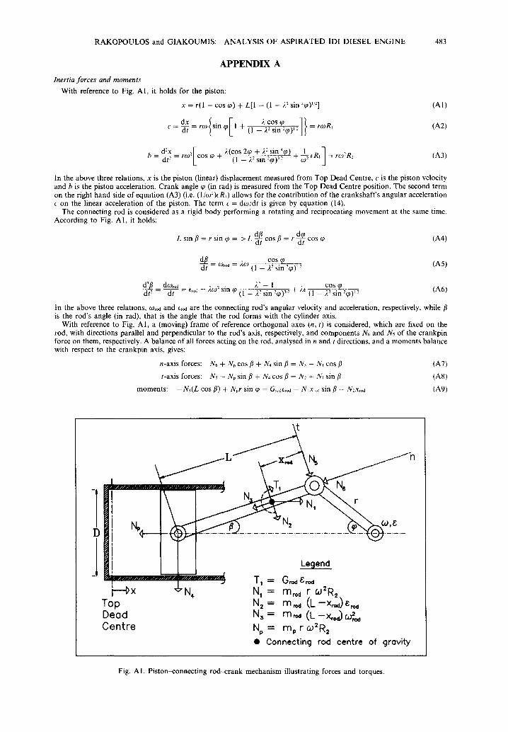
APPENDIX A Inertia forces and moments
With reference to Fig. A1, it holds for the piston:
x = r(l - cos ~0) + L[1 - (1 - 2: sin '~0) L2] (A1)
c = d-7 = ra~ sin ~ 1 + (1 - 2 2 sin -'~o)":J ( = faiR, (A2)
de-v [ 2(cos 2~0 + 22 sin'~P) 1_~ ] b = ~ i ~ = r { o 2 c o s ~ + ( l - 2 2 s i n 2 ~ 0 ) 3-~ + _~R~ =r~o2R,_ (A3)
In the above three relations, x is the piston (linear) displacement measured from Top Dead Centre, c is the piston velocity and b is the piston acceleration. Crank angle ~o (in rad) is measured from the Top Dead Centre position. The second term on the right hand side of equation (A3) (i.e. (I/o~2)ER~) allows for the contribution of the crankshaft 's angular acceleration
on the linear acceleration of the piston. The term E = dco/dt is given by equation (14). The connecting rod is considered as a rigid body performing a rotating and reciprocating movement at the same time.
According to Fig. A1, it holds:
L sin /3 = r sin ~ = > L-~tt cos /3 = r ~ t cos ¢, (A4)
~/ COS (p = a~r~ = 20) (1 - 22 sin 2q9)12 (A5)
d ~ doJ,od 22 - 1 cos ~0 (A6) dt 2 - dt - Ero~ = 2092 sin q~ (1 - 22 sin 2~0) 3'~' + ~'~ (1 - 22 sin 2~9)~.2
tn the above three relations, corod and ero~ are the connecting rod's angular velocity and acceleration, respectively, while fl is the rod's angle (in rad), that is the angle that the rod forms with the cylinder axis.
With reference to Fig. A1, a (moving) frame of reference orthogonal axes (n, t) is considered, which are fixed on the rod, with directions parallel and perpendicular to the rod's axis, respectively, and components N6 and N5 of the crankpin force on them, respectively. A balance of all forces acting on the rod, analysed in n and t directions, and a moments balance with respect to the crankpin axis, gives:
n-axis forces: N6 + Np cos fl + N4 sin fl = N~ - N, cos fl (A7)
t-axis forces: Ns - Np sin fl + N4 cos/3 = N2 + N~ sin/3 (A8)
moments: - N 4 ( L cos/3) + Npr sin q~ = G,oderod -- N~ X~od sin/3 -- N2x~o~ (A9)
~ L ~ N 5 _...1-~b
. . . . . . . . . . . . 2 . . . . . . . . . . . . . . . .
I l>x N, N I = m ~ r w2R2 Top N 2 = m ~ ( L - x ~ ) e ~ Dead N 3 = m,~ (L -x , , ~ ~ Centre Np = mp r CO2R2
• C o n n e c t i n g r o d c e n t r e o f g r e v i t y
Fig. AI . Piston-connecting rod-crank mechanism illustrating forces and torques.

484 RAKOPOULOS and GIAKOUMIS: ANALYSIS OF ASPIRATED IDI DIESEL ENGINE
In the above equations, Np = - - m p r ~ 2 R 2 is the translational force along the cylinder axis acting on the piston assembly to produce its acceleration and N~ = m,odrtO2R2 is the force acting on the connecting rod centre of gravity due to the linear acceleration of the piston. Also, N: -- m ~ ( L - Xrod)Erod and N3 2 = m,o~(L - - x~)coro~, with (L - xr~)E~ being the tangential component and (L - Xroa)Co~ being the normal component of the rod's centre of gravity acceleration with respect to the piston pin. Also, in the above equations, mp is the mass of the piston assembly (piston, rings, wrist pin), m,o~ is the total mass of the connecting rod, Groa is the rod's mass moment of inertia with respect to its centre of gravity, and xrod is the distance between the rod's centre of gravity and the crankpin axis. The gravitational forces are neglected.
The system of equations (A7), (A8) and (A9) can be solved for the unknown forces N4, Ns and N6. Force N4 is the force acting by the piston on the side wall of the cylinder. The sum of the projections of forces Ns and N6 on an axis perpendicular to the crank radius produces the tangential (inertia) force NT~n due to the inertia of the moving parts (piston and connecting rod) acting on the crank, i.e.
NTin = N5 cos(~p +/~) + N~ sin(~p +/~) (A10)