Embed Size (px)
Citation preview
R E N A U LT N I S S A N T E C H N O L O G Y &B U S I N E S S C E N T R E I N D I A P R I VAT E L I M I T E D
Uprating of Naturally Aspirated Gasoline Engine Using Hybrid
Turbocharging SystemRangarajan S , Sundar S M , Venkata Rao G,
Alain Lefebvre, Anand Gurupatham
India GT Conference 2019 Jan 21, 2019
Powertrain CAE - Systems
2
Contents
01 I n t r o d u c t i o n
02 Tu r b o c h a r g e r M o d e l i n g
03 E-charger Modelling
04 S i m u l a t i o n R e s u l t s
05 C o n c l u s i o n
3
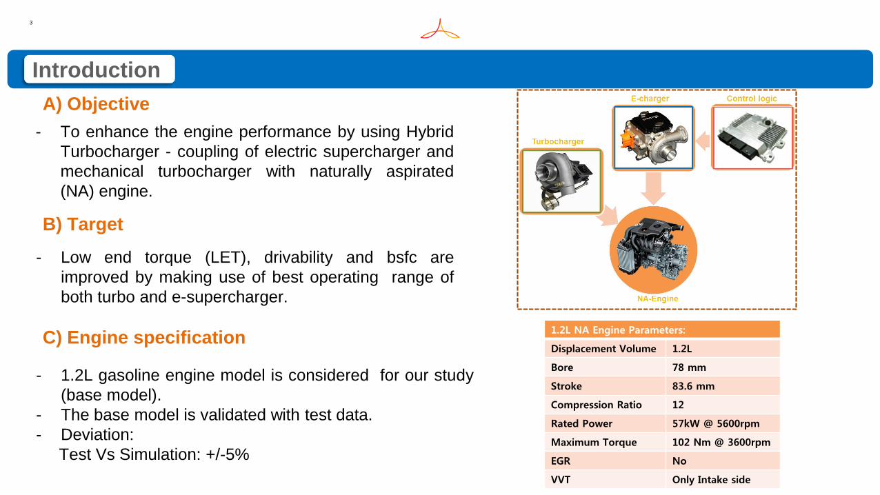
Introduction
A) Objective
B) Target
- To enhance the engine performance by using Hybrid
Turbocharger - coupling of electric supercharger and
mechanical turbocharger with naturally aspirated
(NA) engine.
- Low end torque (LET), drivability and bsfc are
improved by making use of best operating range of
both turbo and e-supercharger.
C) Engine specification
- 1.2L gasoline engine model is considered for our study
(base model).
- The base model is validated with test data.
- Deviation:
Test Vs Simulation: +/-5%
1.2L NA Engine Parameters:
Displacement Volume 1.2L
Bore 78 mm
Stroke 83.6 mm
Compression Ratio 12
Rated Power 57kW @ 5600rpm
Maximum Torque 102 Nm @ 3600rpm
EGR No
VVT Only Intake side
4
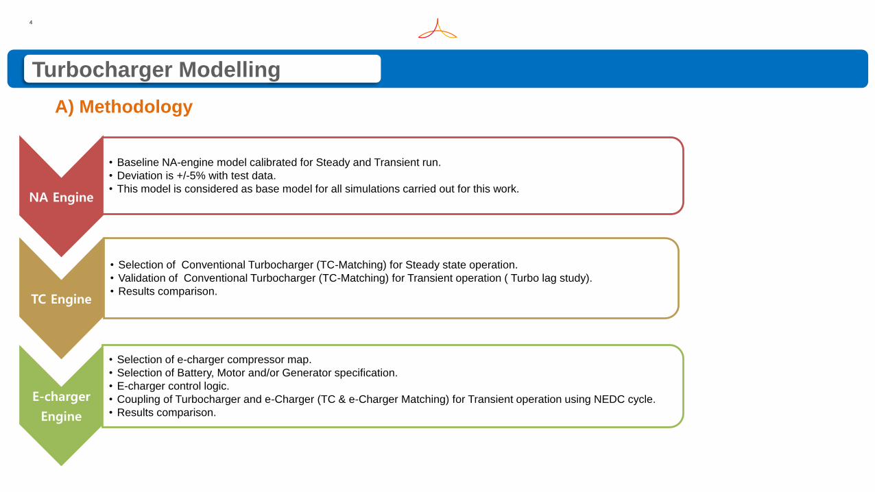
Turbocharger Modelling
A) Methodology
NA Engine
• Baseline NA-engine model calibrated for Steady and Transient run.
• Deviation is +/-5% with test data.
• This model is considered as base model for all simulations carried out for this work.
TC Engine
• Selection of Conventional Turbocharger (TC-Matching) for Steady state operation.
• Validation of Conventional Turbocharger (TC-Matching) for Transient operation ( Turbo lag study).
• Results comparison.
E-charger
Engine
• Selection of e-charger compressor map.
• Selection of Battery, Motor and/or Generator specification.
• E-charger control logic.
• Coupling of Turbocharger and e-Charger (TC & e-Charger Matching) for Transient operation using NEDC cycle.
• Results comparison.
5
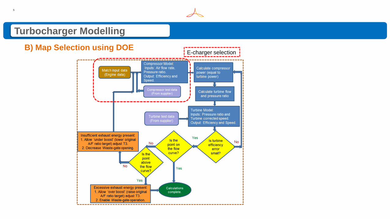
E-charger selectionB) Map Selection using DOE
Turbocharger Modelling
6
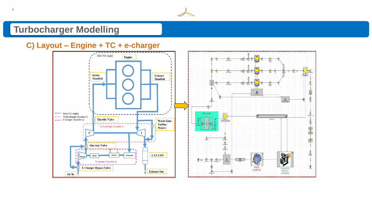
C) Layout – Engine + TC + e-charger
Turbocharger Modelling
7
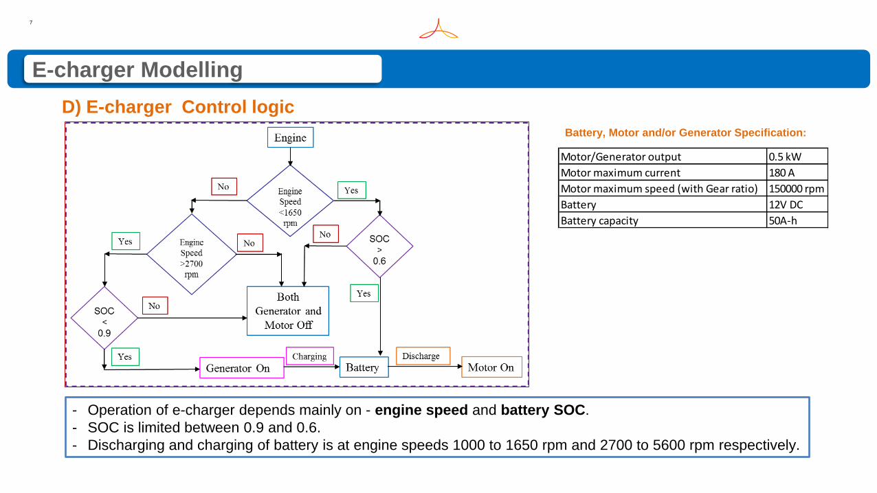
D) E-charger Control logic
- Operation of e-charger depends mainly on - engine speed and battery SOC.
- SOC is limited between 0.9 and 0.6.
- Discharging and charging of battery is at engine speeds 1000 to 1650 rpm and 2700 to 5600 rpm respectively.
Motor/Generator output 0.5 kW
Motor maximum current 180 A
Motor maximum speed (with Gear ratio) 150000 rpm
Battery 12V DC
Battery capacity 50A-h
Battery, Motor and/or Generator Specification:
E-charger Modelling
8
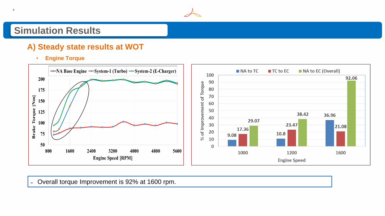
A) Steady state results at WOT
• Engine Torque
˗ Overall torque Improvement is 92% at 1600 rpm.
Simulation Results
9
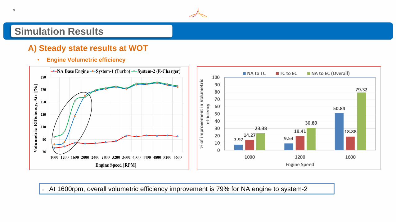
Simulation Results
A) Steady state results at WOT
˗ At 1600rpm, overall volumetric efficiency improvement is 79% for NA engine to system-2
• Engine Volumetric efficiency
10
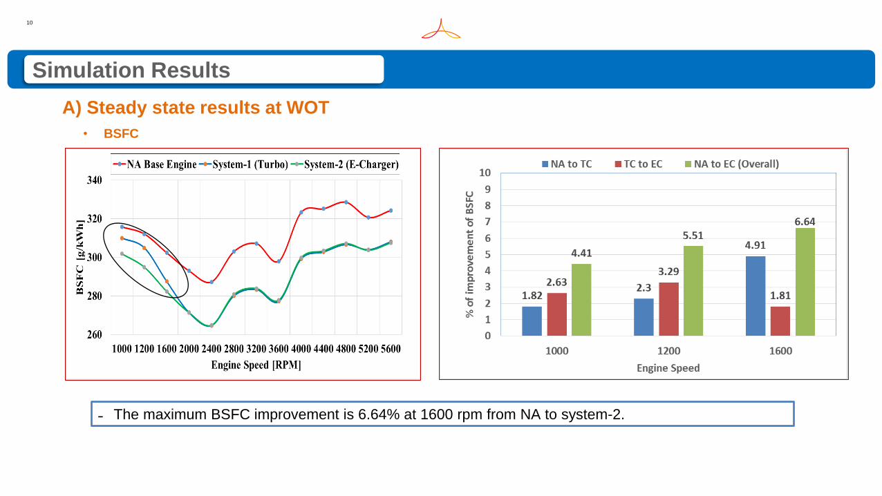
Simulation Results
A) Steady state results at WOT
˗ The maximum BSFC improvement is 6.64% at 1600 rpm from NA to system-2.
• BSFC
11
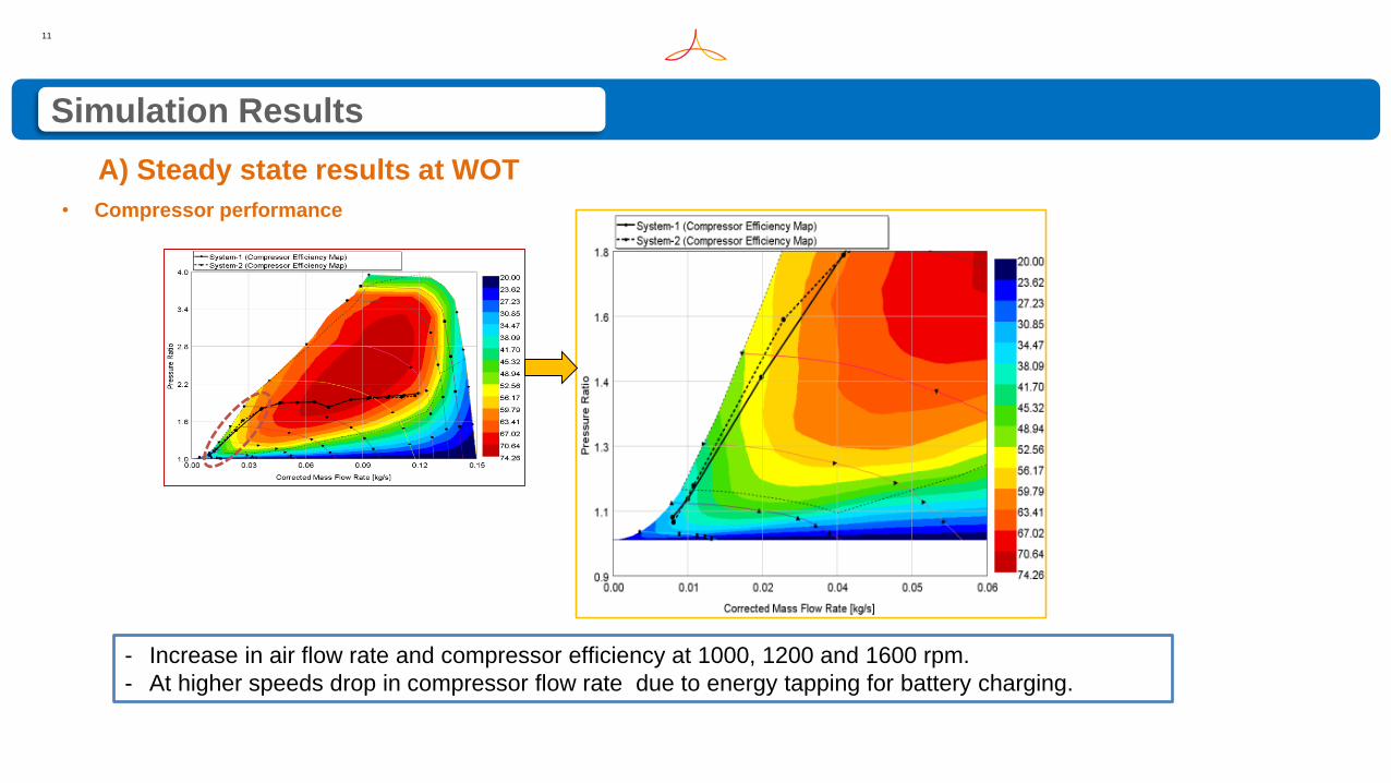
Simulation Results
A) Steady state results at WOT
• Compressor performance
- Increase in air flow rate and compressor efficiency at 1000, 1200 and 1600 rpm.
- At higher speeds drop in compressor flow rate due to energy tapping for battery charging.
12
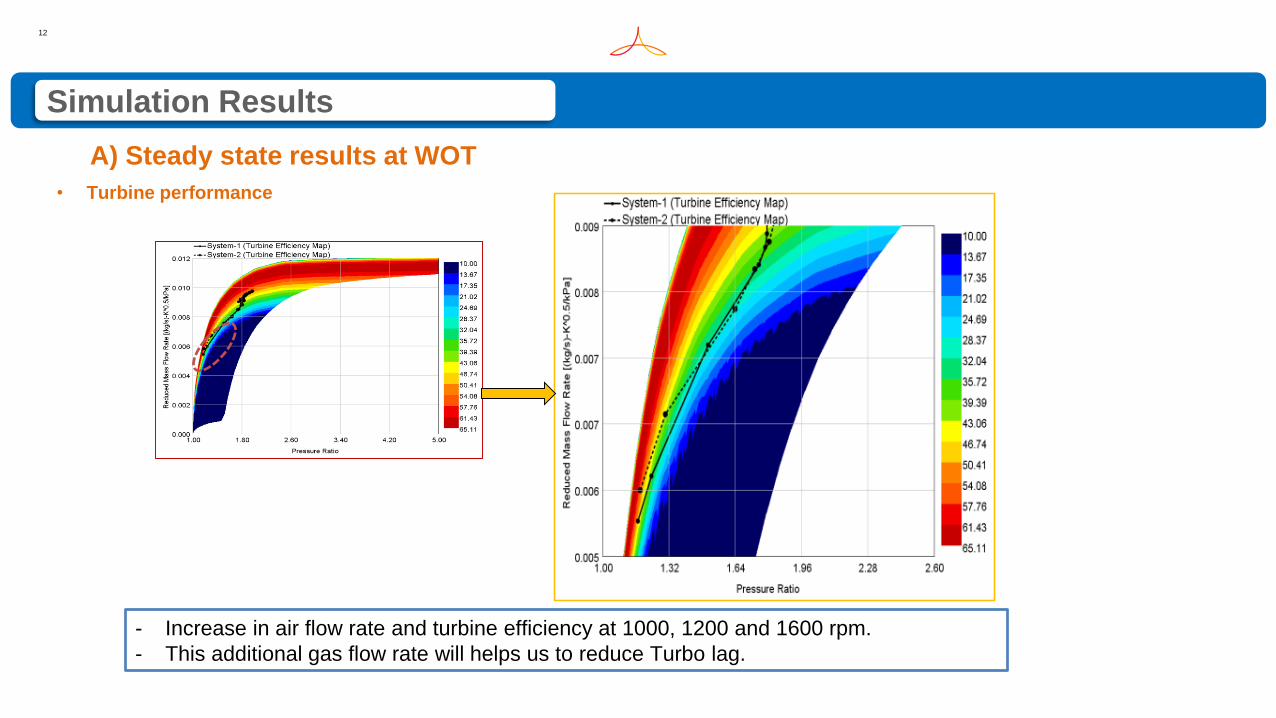
Simulation Results
A) Steady state results at WOT
• Turbine performance
- Increase in air flow rate and turbine efficiency at 1000, 1200 and 1600 rpm.
- This additional gas flow rate will helps us to reduce Turbo lag.
13
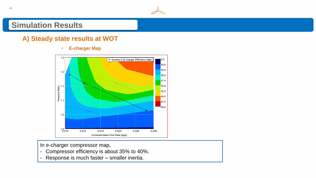
Simulation Results
A) Steady state results at WOT
• E-charger Map
In e-charger compressor map,
- Compressor efficiency is about 35% to 40%.
- Response is much faster – smaller inertia.
14
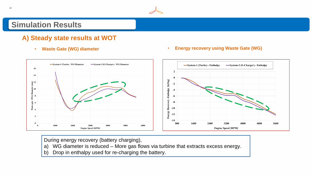
Simulation Results
A) Steady state results at WOT
• Waste Gate (WG) diameter
During energy recovery (battery charging),
a) WG diameter is reduced – More gas flows via turbine that extracts excess energy.
b) Drop in enthalpy used for re-charging the battery.
• Energy recovery using Waste Gate (WG)
15
Simulation Results
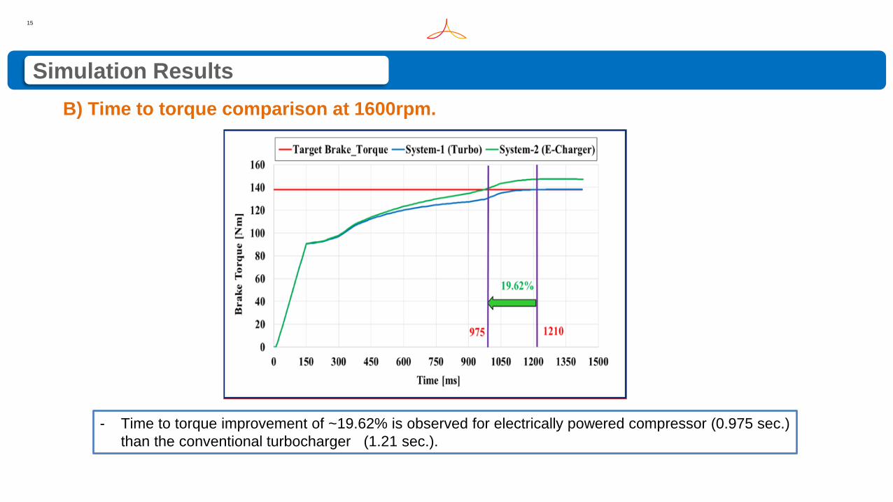
B) Time to torque comparison at 1600rpm.
- Time to torque improvement of ~19.62% is observed for electrically powered compressor (0.975 sec.)
than the conventional turbocharger (1.21 sec.).
16
Simulation Results
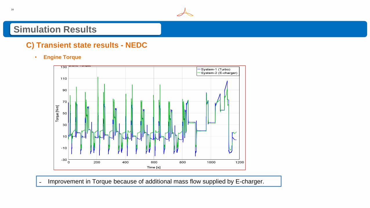
C) Transient state results - NEDC
• Engine Torque
˗ Improvement in Torque because of additional mass flow supplied by E-charger.
17
Simulation Results
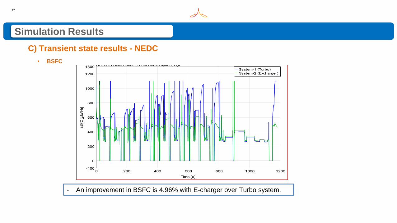
C) Transient state results - NEDC
- An improvement in BSFC is 4.96% with E-charger over Turbo system.
• BSFC
18
Simulation Results
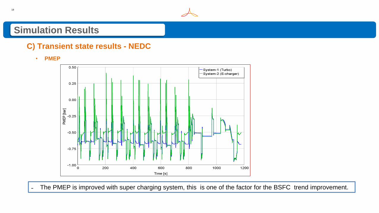
C) Transient state results - NEDC
˗ The PMEP is improved with super charging system, this is one of the factor for the BSFC trend improvement.
• PMEP
19
Simulation Results
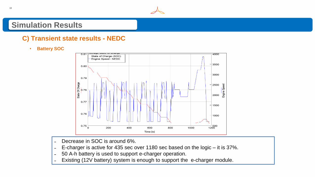
C) Transient state results - NEDC
˗ Decrease in SOC is around 6%.
˗ E-charger is active for 435 sec over 1180 sec based on the logic – it is 37%.
˗ 50 A-h battery is used to support e-charger operation.
˗ Existing (12V battery) system is enough to support the e-charger module.
• Battery SOC
20
Conclusion
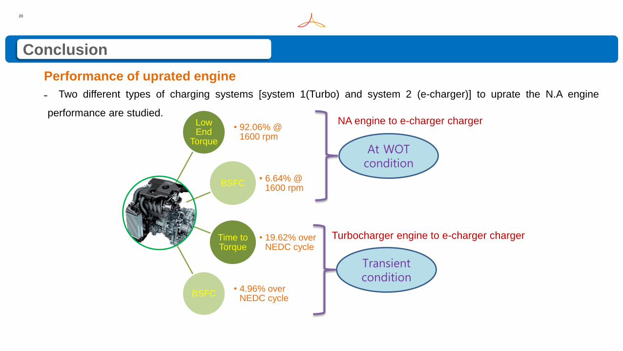
Low End
Torque
• 92.06% @ 1600 rpm
BSFC• 6.64% @
1600 rpm
Time to Torque
• 19.62% over NEDC cycle
BSFC• 4.96% over
NEDC cycle
Performance of uprated engine
NA engine to e-charger charger
˗ Two different types of charging systems [system 1(Turbo) and system 2 (e-charger)] to uprate the N.A engine
performance are studied.
At WOT condition
Transient condition
Turbocharger engine to e-charger charger
21
References
˗ [1] Prasad Sajjan Divekar, Beshah Ayalew and Robert Prucka., “Coordinated Electric Supercharging and
Turbo-Generation for a Diesel Engine”, SAE Technical Paper, 2010-01-1228, 2010.
˗ [2] P.Pallotti, E.Torella, J.New, M.Criddle and J.Brown., “Application of an Electric Boosting System to a Small,
Four-Cylinder S.I. Engine”, SAE International 2003-32-0039, 2003.
˗ [3] Yukio Yamashita. et al., “Development of Electric Supercharger to Facilitate the Downsizing of Automobile
Engines”, Mitsubishi Heavy Industries Technical Review Vol.47 No. 4, 2010.
˗ [4] Byeongil AN. et al., “Development of Two-stage Electric Turbocharging system for Automobiles”, Mitsubishi
Heavy Industries Technical Review Vol.52 No. 1, 2015.
˗ [5] Alain Lefebvre, Stephane Guilain., “Transient response of a Turbocharged SI Engine with an electrical boost
pressure supply”, SAE, Japan, 2003-01-1844, 2003.
˗ [6] WATSON N., and JANOTA M.S., “Turbocharging the Internal Combustion Engine”, Wiley-Inter science, 1982.
˗ [7] HEYWOOD, J.B., “Internal Combustion Engine Fundamentals”, Mc Graw-Hill, Inc., 2011.
22
Acknowledgement
We would like to acknowledge with gratitude, for their extended support provided to our work.
˗ Vinayaga Moorthy – DGM, RNTBCI.
˗ Srinivasan Seethapathy – Dy. Manager, Intake and Exhaust system, RNTBCI.
˗ Badrigari Manishankar – Senior Engineer, Battery Sizing, RNTBCI.
˗ Gamma Technologies – Global support team.

23
Queries ?