Embed Size (px)
Citation preview

Operation
Engine
Engine Models:
KG2204 Naturally AspiratedKG2204T Turbocharged
Liquefied Petroleum Gas (LPG)/Propane/Natural Gas (NG) Fueled
TP-6901 3/16a

INTRODUCTIONThis manual provides operating and maintenance instructions for KOHLER Engine Models KG2204 and KG2204T. Keep this manual with the equipment for future reference. Refer to the KG2204 and KG2204T Service Manual for detailed information on adjusting and servicing the engine.
Information in this publication represents data available at the time of print. KOHLER Co. reserves the right to change this publication and the products represented without notice and without any obligation or liability whatsoever.
This engine operates on either Propane, Liquefied Petroleum Gas (LPG) or Natural Gas (NG), which are extremely flammable and explosive. Installation and repair of LPG/NG systems must be performed only by qualified LPG/NG technicians. Read this manual and carefully follow all procedures and safety precautions to ensure proper equipment operation and to avoid bodily injury.
Regular maintenance is necessary for safe and efficient operation. Inspect the engine often and perform required maintenance at prescribed intervals. Service work must be performed by appropriately skilled and suitably trained maintenance personnel who are familiar with engine diagnostics and repair.
Unless otherwise specified, all units of measurement are metric, followed by the Imperial (U.S.) equivalent.
California Proposition 65
WARNING!Engine exhaust from this product contains chemicals
known to the State of California to cause cancer, birth defects, or other reproductive harm.

3
Section 1 Engine Identification and Technical Support1.1 Know Your Engine . . . . . . . . . . . . . . . . . . . . . . . . . . . . . . . . . . . . . . . . . . . . . . . . . . . . . . . . . . . 5
Purchase Date . . . . . . . . . . . . . . . . . . . . . . . . . . . . . . . . . . . . . . . . . . . . . . . . . . . . . . . . . . . . . 5
1.2 Related Literature . . . . . . . . . . . . . . . . . . . . . . . . . . . . . . . . . . . . . . . . . . . . . . . . . . . . . . . . . . . . 5
1.3 Service Parts . . . . . . . . . . . . . . . . . . . . . . . . . . . . . . . . . . . . . . . . . . . . . . . . . . . . . . . . . . . . . . . . 5
Section 2 Safety Precautions2.1 Safety Alerts . . . . . . . . . . . . . . . . . . . . . . . . . . . . . . . . . . . . . . . . . . . . . . . . . . . . . . . . . . . . . . . . 7
2.2 Safety Information For This Engine . . . . . . . . . . . . . . . . . . . . . . . . . . . . . . . . . . . . . . . . . . . . . 7
Section 3 Components and Maintenance Locations3.1 Model KG2204 Engine Side Views . . . . . . . . . . . . . . . . . . . . . . . . . . . . . . . . . . . . . . . . . . . . . 11
3.2 Model KG2204 Front and Rear Views . . . . . . . . . . . . . . . . . . . . . . . . . . . . . . . . . . . . . . . . . . . 12
3.3 Model KG2204T Engine Side Views . . . . . . . . . . . . . . . . . . . . . . . . . . . . . . . . . . . . . . . . . . . . 13
3.4 Model KG2204T Front and Rear Views . . . . . . . . . . . . . . . . . . . . . . . . . . . . . . . . . . . . . . . . . . 14
Section 4 Operation4.1 Introduction . . . . . . . . . . . . . . . . . . . . . . . . . . . . . . . . . . . . . . . . . . . . . . . . . . . . . . . . . . . . . . . . 15
4.2 Fuel System . . . . . . . . . . . . . . . . . . . . . . . . . . . . . . . . . . . . . . . . . . . . . . . . . . . . . . . . . . . . . . . . 15Components . . . . . . . . . . . . . . . . . . . . . . . . . . . . . . . . . . . . . . . . . . . . . . . . . . . . . . . . . . . . . . 15Fuel Specifications . . . . . . . . . . . . . . . . . . . . . . . . . . . . . . . . . . . . . . . . . . . . . . . . . . . . . . . . . 19NG to LPG Conversion . . . . . . . . . . . . . . . . . . . . . . . . . . . . . . . . . . . . . . . . . . . . . . . . . . . . . . 20
4.3 Before Starting . . . . . . . . . . . . . . . . . . . . . . . . . . . . . . . . . . . . . . . . . . . . . . . . . . . . . . . . . . . . . 21
4.4 Starting . . . . . . . . . . . . . . . . . . . . . . . . . . . . . . . . . . . . . . . . . . . . . . . . . . . . . . . . . . . . . . . . . . . 22
4.5 Cold Weather Starting . . . . . . . . . . . . . . . . . . . . . . . . . . . . . . . . . . . . . . . . . . . . . . . . . . . . . . . 23
4.6 Monitoring Engine Operation . . . . . . . . . . . . . . . . . . . . . . . . . . . . . . . . . . . . . . . . . . . . . . . . . 24
4.7 Stopping . . . . . . . . . . . . . . . . . . . . . . . . . . . . . . . . . . . . . . . . . . . . . . . . . . . . . . . . . . . . . . . . . . 24
Section 5 Maintenance5.1 Introduction . . . . . . . . . . . . . . . . . . . . . . . . . . . . . . . . . . . . . . . . . . . . . . . . . . . . . . . . . . . . . . . . 25
5.2 Fluid Specifications . . . . . . . . . . . . . . . . . . . . . . . . . . . . . . . . . . . . . . . . . . . . . . . . . . . . . . . . . 26Oil Recommendations . . . . . . . . . . . . . . . . . . . . . . . . . . . . . . . . . . . . . . . . . . . . . . . . . . . . . . 26Grease Recommendations . . . . . . . . . . . . . . . . . . . . . . . . . . . . . . . . . . . . . . . . . . . . . . . . . . . 26Coolant Recommendations . . . . . . . . . . . . . . . . . . . . . . . . . . . . . . . . . . . . . . . . . . . . . . . . . . 26
5.3 Periodic Maintenance Schedule . . . . . . . . . . . . . . . . . . . . . . . . . . . . . . . . . . . . . . . . . . . . . . . 27
5.4 Engine . . . . . . . . . . . . . . . . . . . . . . . . . . . . . . . . . . . . . . . . . . . . . . . . . . . . . . . . . . . . . . . . . . . . 28Check Engine Oil . . . . . . . . . . . . . . . . . . . . . . . . . . . . . . . . . . . . . . . . . . . . . . . . . . . . . . . . . . 28Change Engine Oil and Oil Filter . . . . . . . . . . . . . . . . . . . . . . . . . . . . . . . . . . . . . . . . . . . . . . 28Check and Clean the Air Filter . . . . . . . . . . . . . . . . . . . . . . . . . . . . . . . . . . . . . . . . . . . . . . . . 31Replace the Air Filter . . . . . . . . . . . . . . . . . . . . . . . . . . . . . . . . . . . . . . . . . . . . . . . . . . . . . . . 31Check and Adjust the Spark Plugs . . . . . . . . . . . . . . . . . . . . . . . . . . . . . . . . . . . . . . . . . . . . . 31Replace the Spark Plugs . . . . . . . . . . . . . . . . . . . . . . . . . . . . . . . . . . . . . . . . . . . . . . . . . . . . 33Ignition Timing . . . . . . . . . . . . . . . . . . . . . . . . . . . . . . . . . . . . . . . . . . . . . . . . . . . . . . . . . . . . 34

4
5.5 Electrical System . . . . . . . . . . . . . . . . . . . . . . . . . . . . . . . . . . . . . . . . . . . . . . . . . . . . . . . . . . . 34Check Battery and Connections . . . . . . . . . . . . . . . . . . . . . . . . . . . . . . . . . . . . . . . . . . . . . . . 34Check and Adjust the Drive Belt . . . . . . . . . . . . . . . . . . . . . . . . . . . . . . . . . . . . . . . . . . . . . . . 34Replace the Drive Belt . . . . . . . . . . . . . . . . . . . . . . . . . . . . . . . . . . . . . . . . . . . . . . . . . . . . . . 36Check Wiring and Electrical Connections . . . . . . . . . . . . . . . . . . . . . . . . . . . . . . . . . . . . . . . 37
5.6 Cooling System . . . . . . . . . . . . . . . . . . . . . . . . . . . . . . . . . . . . . . . . . . . . . . . . . . . . . . . . . . . . 38Check Coolant Level and Condition . . . . . . . . . . . . . . . . . . . . . . . . . . . . . . . . . . . . . . . . . . . . 38Check Hoses and Clamps . . . . . . . . . . . . . . . . . . . . . . . . . . . . . . . . . . . . . . . . . . . . . . . . . . . 38
5.7 Fuel System . . . . . . . . . . . . . . . . . . . . . . . . . . . . . . . . . . . . . . . . . . . . . . . . . . . . . . . . . . . . . . . 39Check Fuel Supply Pipe and Connections . . . . . . . . . . . . . . . . . . . . . . . . . . . . . . . . . . . . . . . 39Check Fuel Level (LPG only) . . . . . . . . . . . . . . . . . . . . . . . . . . . . . . . . . . . . . . . . . . . . . . . . . 39
Section 6 Troubleshooting6.1 Introduction . . . . . . . . . . . . . . . . . . . . . . . . . . . . . . . . . . . . . . . . . . . . . . . . . . . . . . . . . . . . . . . 41
6.2 Troubleshooting . . . . . . . . . . . . . . . . . . . . . . . . . . . . . . . . . . . . . . . . . . . . . . . . . . . . . . . . . . . . 41
Section 7 Storage7.1 Preparation . . . . . . . . . . . . . . . . . . . . . . . . . . . . . . . . . . . . . . . . . . . . . . . . . . . . . . . . . . . . . . . . 43
7.2 Short-Term Storage (Less than 30 days) . . . . . . . . . . . . . . . . . . . . . . . . . . . . . . . . . . . . . . . . 43
7.3 Long-Term Storage (More than 30 days) . . . . . . . . . . . . . . . . . . . . . . . . . . . . . . . . . . . . . . . . 43
7.4 Maintenance While In Storage . . . . . . . . . . . . . . . . . . . . . . . . . . . . . . . . . . . . . . . . . . . . . . . . 43
7.5 Removal From Storage . . . . . . . . . . . . . . . . . . . . . . . . . . . . . . . . . . . . . . . . . . . . . . . . . . . . . . 44
Section 8 Specifications8.1 Engine Specifications . . . . . . . . . . . . . . . . . . . . . . . . . . . . . . . . . . . . . . . . . . . . . . . . . . . . . . . 45
8.2 Specifications of Main Components . . . . . . . . . . . . . . . . . . . . . . . . . . . . . . . . . . . . . . . . . . . 46
8.3 Adjustment Specifications . . . . . . . . . . . . . . . . . . . . . . . . . . . . . . . . . . . . . . . . . . . . . . . . . . . 46
8.4 Torque Specifications . . . . . . . . . . . . . . . . . . . . . . . . . . . . . . . . . . . . . . . . . . . . . . . . . . . . . . . 46
8.5 Standard Torque Specifications . . . . . . . . . . . . . . . . . . . . . . . . . . . . . . . . . . . . . . . . . . . . . . . 47

ENGINE IDENTIFICATION AND TECHNICAL SUPPORT
TP-6901 3/16a Engine Identification and Technical Support 5
Section 1 Engine Identification andTechnical Support
1.1 KNOW YOUR ENGINEProduct identification numbers determine service parts. Record the product identification numbers in the spaces below immediately after unpacking the products so that the numbers are readily available for future reference.
Engine Identification
Record the product identification information from the engine nameplate.
Model Designation: __________________________
Serial Number: __________________________
Purchase DateUpon purchase of your KOHLER equipment, record the purchase date for reference when communicating with your authorized KOHLER distributor/dealer.
1.2 RELATED LITERATURERelated Literature identifies related literature available for the KG2204 and KG2204T engines. Only trained and qualified personnel should install or service this engine.
1.3 SERVICE PARTSContact a KOHLER authorized distributor/dealer for all maintenance, service, and engine parts. To find a KOHLER authorized distributor/dealer, visit KOHLERPower.com or call 1-800-544-2444 (U.S. and Canada).
Literature Type Part Number
KOHLER Models KG2204 and KG2204T Service Manual
TP-6902
KOHLER Models KG2204 and KG2204T Service Manual / Troubleshooting / Diagnostics
TP-6903
KOHLER Models KG2204 and KG2204T Service Parts Manual
TP-6904

ENGINE IDENTIFICATION AND TECHNICAL SUPPORT
6 Engine Identification and Technical Support TP-6901 3/16a

SAFETY PRECAUTIONS
TP-6901 3/16a Safety Precautions 7
Section 2 Safety Precautions
2.1 SAFETY ALERTS
NOTE:A Note is used to inform you of important installation, operation, or maintenance information.
2.2 SAFETY INFORMATION FOR THIS ENGINE
! DANGERDanger indicates the presence of a hazard that will cause severe personal injury, death, or substantial property damage.
NOTICENotice communicates installation, operation, or maintenance information that is safety related but not hazard related.
WARNING!Warning indicates the presence of a hazard that can cause severe personal injury, death, or substantial property damage.
! CAUTIONCaution indicates the presence of a hazard that will or can cause minor personal injury or property damage.
WARNING!Carbon monoxide can cause severe nausea, fainting, or death.
Avoid inhaling exhaust fumes.
Engine exhaust gases contain poisonous carbon monoxide. Carbon monoxide is odorless, colorless, and can cause death if inhaled.
WARNING!
Risk of Fire. Can cause severe injury or death.
Do not smoke or permit flames or sparks near fuels or the fuel system.
! CAUTION
Electrical shock can cause injury.
Do not touch wires while engine is running.
WARNING!Rotating parts can cause severe injury.
Stay away while the engine is in operation.
Keep hands, feet, hair, and clothing away from all moving parts to prevent injury. Never operate the engine with covers, shrouds, or guards removed.
WARNING!Hot parts can cause severe burns.
Do not touch engine while operating or just after stopping.
Never operate engine with heat shields or guards removed.

SAFETY PRECAUTIONS
8 Safety Precautions TP-6901 3/16a
WARNING!Hot liquid can cause severe burns.
Do not loosen radiator cap while engine is operating or warm to touch.
Liquid coolant can be extremely hot from operation. Turning radiator cap when engine is hot can allow steam and scalding liquid to blow out and burn you severely. Shut off machine. Only remove radiator cap when cool enough to touch with bare hands. Slowly loosen cap to the first stop to relieve pressure before removing completely.
WARNING!
Accidental starts can cause severe injury or death.
Disconnect and ground spark plug leads before servicing.
Before working on engine or equipment, disable engine as follows: 1) Disconnect spark plug leads. 2) Disconnect negative (–) battery cable from battery.
Before disconnecting negative (–) ground cable, make sure all switches are OFF. If ON, a spark will occur at the ground cable terminal which could cause an explosion if hydrogen gas or LPG/NG fuel vapors are present.
WARNING!Explosive fuel can cause fires and severe burns.
If a gaseous odor is detected, ventilate the area and contact an authorized service technician.
LPG (Liquefied Petroleum Gas) is extremely flammable and tends to settle in low areas where a spark or flame could ignite the gas. Do not start or operate this engine in a poorly ventilated area where leaking gas could accumulate and endanger the safety of persons in the area.
NG (Natural Gas) is extremely flammable, is lighter than air, and rises. Do not start or operate this engine in a poorly ventilated are where leaking gas could accumulate and endanger the safety of persons in the area.
To ensure personal safety, installation and repair of LPG/NG fuel supply systems must be performed only by qualified LPG/NG system technicians. Improperly installed and maintained LPG/NG equipment could cause the fuel supply system or other components to malfunction, causing gas leaks.
Observe federal, state, and local laws governing LPG/NG fuel, storage, and systems.
WARNING!
Handling caustic engine fluids and chemical products can cause severe chemical burns, nausea, fainting, or death.
Most chemicals such as used engine oil, antifreeze/coolant, rust proofing agent, inhibiting oil, degreasing agent, spray paint, and adhesives are hazardous to health.
Read and follow the user information found on the packaging. Avoid inhalation and skin contact. Use only in well-ventilated areas and use a protective mask when spraying. Store engine fluids and chemical products in a locked cabinet. Contact your local recycling center for disposal information and locations.
Fire-damaged or burned O-rings may cause the formation of hydrofluoric acid. Contact with hydrofluoric acid may cause severe skin irritation and chemical burns. O-rings and other fluoroelastomer seals exposed to fire or temperatures above 316°C (600°F) (i.e., during welding) may decompose forming hydrofluoric acid. Avoid inhalation or skin contact. Do not incinerate O-rings. Dispose of O-ring waste material in a responsible manner.

SAFETY PRECAUTIONS
TP-6901 3/16a Safety Precautions 9
WARNING!Explosive fuel vapors. Can cause severe injury or death.
Use extreme care when handling, storing, and using fuels.
Gas fuel leaks. Explosive fuel vapors can cause severe injury or death. Fuel leakage can cause an explosion. Check the LPG vapor or natural gas fuel system for leakage by using a soap and water solution with the fuel system test pressurized to 6–8 ounces per square inch (10–14 inches water column). Do not use a soap solution containing either ammonia or chlorine because both prevent bubble formation. A successful test depends on the ability of the solution to bubble.
Used engine oil. Contact with used engine oil may cause severe skin irritation. Repeated and prolonged skin exposure may have other health risks. Used engine oil is a suspected carcinogen. Avoid contact with skin. Thoroughly wash your hands and nails with soap and water shortly after handling used engine oil. Wash or dispose of clothing or rags containing used engine oil. Dispose of used engine oil in a responsible manner. Contact your local recycling center for disposal information and locations.

SAFETY PRECAUTIONS
10 Safety Precautions TP-6901 3/16a

COMPONENTS AND MAINTENANCE LOCATIONS
TP-6901 3/16a Components and Maintenance Locations 11
Section 3 Components and MaintenanceLocations
3.1 MODEL KG2204 ENGINE SIDE VIEWS
Figure 3-1
1 Rocker Arm Cover 7 Air-Fuel Mixer 13 Oil Pan 19Knock Sensor (if equipped with turbocharger)
2 Rear Hanger 8 Throttle Body 14Battery Charging Alternator
20Oil Cooler Adapter (not included on all models)
3Crankcase Breather
9 TMAP Sensor1
1) Air Temperature / Manifold Absolute Pressure (TMAP)
15 Oil Pump Drive 21 Oil Pan Drain Plug
4 Spark Plug Wires 10 Intake Manifold 16 Ignition Coil 22Oil Pressure Sender
5 Oil Filler Cap 11 Flywheel 17Crankshaft Position Sensor
23 Oil Filter Base
6 Front Hanger 12 Exhaust Manifold 18Oil Dipstick and Tube
24 Oil Filter
2
3 45
7
1
8 9
1213
10
14
6
21
17
16
18
1923
24
22
11
15
20
K0695 K0403

COMPONENTS AND MAINTENANCE LOCATIONS
12 Components and Maintenance Locations TP-6901 3/16a
3.2 MODEL KG2204 FRONT AND REAR VIEWS
Figure 3-2
1 Air-Fuel Mixer 8 Ignition Coil 15Crankshaft Position Sensor
22 Flywheel
2 Throttle Body 9 Oil Dipstick 16 Timing Cover 23Exhaust Manifold Studs
3 TMAP Sensor 10 Fuel Control Valve 17 Oil Drain Plug 24 Oil Pan
4Upper Intake Manifold
11Upper Coolant Outlet
18Oil Pressure Sensor (PGS)
25 Exhaust Manifold
5 PCV Valve 12Coolant Temperature Sensor
19 Oil Filter Base 26Battery Charging Alternator
6 Rocker Arm Cover 13 Drive Belt 20Oil Cooler Adapter (not included on all models)
27 Water Pump Inlet
7 Oil Filter 14Vibration Dampener
21Lower Intake Manifold
2
3 4
5
7
1
8
9
14
15
10
17
6
21
22
11
1
12
13
19
1623
24
26
K0693K0647
27
18
20
25

COMPONENTS AND MAINTENANCE LOCATIONS
TP-6901 3/16a Components and Maintenance Locations 13
3.3 MODEL KG2204T ENGINE SIDE VIEWS
Figure 3-3
1 Regulator to FCV Hose 9 Throttle Body 16 Oil Pump Drive2 FCV to Mixer Hose 10 TMAP Sensor1
1) Air Temperature / Manifold Absolute Pressure (TMAP)
17 Crankshaft Position Sensor3 Fuel Control Valve (FCV) 11 Intake Manifold 18 Ignition Coil4 Rear Hanger 12 Flywheel 19 Oil Dipstick and Tube
5 Oil Filter 13 Turbocharger 20Oil Cooler Adapter and Stand-off
6 Spark Plug Wires 14 Oil Pan 21 Engine Control Module7 Oil Filler Cap 15 Battery Charging Alternator 22 Turbo Oil Feed Line8 Front Hanger
2
4
1
611
idGM88249
12
13
14
15
16
1718192021
22
3
7 8 910
5

COMPONENTS AND MAINTENANCE LOCATIONS
14 Components and Maintenance Locations TP-6901 3/16a
3.4 MODEL KG2204T FRONT AND REAR VIEWS
Figure 3-4
1 Throttle Body 9Coolant Temperature Sensor
17 Crankshaft Position Sensor
2 Upper Intake Manifold 10 Lower Intake Manifold 18 Timing Cover3 Fuel Control Valve 11 Turbo Oil Feed Line 19 Oil Pressure Sensor4 Oil Filter 12 Turbocharger 20 Flywheel5 Coil 13 Drive Belt 21 Dual Fuel Regulator (DFR)6 Spark Plug Wires 14 Turbo Oil Return Line 22 Air-Fuel Mixer7 Oil Dipstick 15 Vibration Dampener 23 DFR Breather Hose8 Upper Coolant Outlet 16 Oil Pan
idGM88249
2
4
1
6
11
12
131415
16
17
18
19
2021
23
3
5
7 8 9
10
22

OPERATION
TP-6901 3/16a Operation 15
Section 4 Operation
4.1 INTRODUCTIONThe KG2204 and KG2204T are four-stroke internal combustion engines certified to operate on either Propane, Liquid Petroleum Gas (LPG) or Natural Gas (NG). System configuration is factory preset for NG. Instructions for switching to LPG are provided within this section.
The fuel system on this engine is a closed loop design. As the engine runs, sensors located at various points within the system provide continuous operating feedback to the Engine Control Module (ECM). The ECM adjusts the engine speed, ignition timing, and fuel supply in response to changes in the applied load, surrounding air temperature, operating temperature of the engine, and amount of oxygen present in the exhaust.
Refer to the equipment Operation Manual for specific information on how fault codes are displayed.
4.2 FUEL SYSTEM
Components
Fuel Shut-Off Valves
Figure 4-1
The fuel supply contains two fuel shut-off valves located upstream from the fuel connection point on the engine. Each valve consists of a 12V solenoid and a normally closed port. When energized, the solenoid opens the valve and allows the LPG/NG vapor to flow through the system.
The valves are open during the engine cranking and run cycles. Voltage to the valves is controlled by the ECM.
K0404

OPERATION
16 Operation TP-6901 3/16a
Fuel Pressure Regulator
Figure 4-2
The fuel pressure regulator modulates the pressure of the LPG/NG vapor to the air-fuel mixer.
The fuel pressure regulator is not adjustable. However, a selector at the base of the regulator is rotated when switching from NG to LPG and back. See “NG to LPG Conversion” on page 20 for instructions.
Fuel Control Valvez
Figure 4-3
The fuel control valve is an ECM-controlled vacuum switch that adjusts the fuel pressure delivered from the fuel pressure regulator to the air-fuel mixer.
Air-Fuel Mixer
Figure 4-4
The air-fuel mixer is mounted in the air stream ahead of the throttle. It is a nonadjustable metering device that combines LPG/NG vapor with intake air for combustion.fThrottle Body
K0692
K0379
NOTICE
Avoid the possibility of component damage. The air-fuel mixer is an emission control device. Components inside the mixer are specifically calibrated to meet the engine’s emission requirements and should never be disassembled or rebuilt. If the mixer fails to function correctly, contact your KOHLER authorized distributor or dealer.
K0380

OPERATION
TP-6901 3/16a Operation 17
Throttle BodyFigure 4-5
Figure 4-6
The throttle body controls the operating speed of the engine according to input from the ECM. Defaults programmed into the ECM software, along with throttle position sensors, allow the ECM to control the overall operation of the engine in response to changing speeds and loads.
Turbocharger
Figure 4-7
The Model KG2204T engine is equipped with a turbocharger. The turbocharger utilizes exhaust gas flowing through the turbine to spin a compressor. The turbocharger compressor increases boost pressure and density of the air/fuel mixture entering the intake manifold resulting in higher power output compared to the naturally aspirated engine. A wastegate on the turbocharger bypasses exhaust gas around the turbine when the boost pressure reaches a maximum limit.
Turbocharger Oil LinesThe Model KG2204T engine is equipped with a turbocharger. The turbocharger bearings require oil for lubrication and cooling. Oil is fed to the turbocharger bearings from the oil supply line on the top side of the bearing housing and returned to the oil sump through a line connecting the bottom side of the bearings to the sump.
Charge Air Cooler
Figure 4-8
The Model KG2204T engine is equipped with a charge air cooler. The charge air cooler (A) cools the compressed air/fuel mixture before it enters the intake manifold. The cooler intake manifold charge helps maintain emissions at the high power level of the turbocharged engine.
K0679
idGM91526
idGM92075
A

OPERATION
18 Operation TP-6901 3/16a
Engine Control Module (ECM)
Figure 4-9
The ECM is a digital controller that oversees the various operating parameters of the engine. The ECM receives input data from sensors mounted to the engine and fuel system, and then outputs various signals to adjust engine operation.
The ECM also performs diagnostic functions on the fuel system. If a malfunction occurs, the ECM sends a fault signal to alert the operator to the problem. A corresponding Diagnostic Trouble Code (DTC) is generated and stored in memory within the ECM. A technician can then use a computerized diagnostic scan tool to retrieve the stored DTC number(s) and identify the problem.
Sensors
Heated Exhaust Gas Oxygen (HEGO) Sensor
The Heated Exhaust Gas Oxygen (HEGO) sensor measures the amount of oxygen present in the exhaust stream to determine whether the air-fuel ratio is too rich or too lean.
Air Temperature / Manifold Absolute Pressure (TMAP) Sensor
The Air Temperature / Manifold Absolute Pressure (TMAP) sensor monitors the absolute pressure in the intake manifold. This sensor also measures the temperature of the incoming air. Data returned by the TMAP sensor prompts the ECM to adjust the air-fuel mixture as needed.
Crankshaft Position Sensor
Crankshaft Position Sensor (CPS) measures the rotary speed and crankshaft turning angle. The ECM ensures the ignition timing for each cylinder depending on the turning signal. The sensor, which consists of a permanent magnet and coil, is installed on the timing gear cover next to the crankshaft pulley. When the crankshaft is turning, the gear ring passes the sensor at different speeds and causes a change of magnet resistance at the sensor to produce a changeable signal.
Throttle Position Sensor (TPS)
The electronic throttle control device incorporates an internal Throttle Position Sensor (TPS), which provides output signals to the ECM as to the location of the throttle shaft and blade. The ECM will use the signal to monitor and adjust the engine speed.
Engine Coolant Temperature Sensor
The engine coolant temperature sensor provides engine coolant temperature data to the ECM. The ECM uses this data to adjust for cold starting conditions, and regulates various fuel and emission control functions.
Engine Oil Pressure Sender
The engine oil pressure sender ensures sufficient lubrication throughout the engine. The sender is a pressure valve that is monitored by the ECM. A drop in pressure will trigger a fault code.
Figure 4-10
Up-Stream Throttle Manifold Air Pressure (MAP) Sensor (KG2204T)
The Up-stream Thr ottle Manifold Air Pressure sensor monitors the absolute pressure in the air induction system up-stream of the throttle. Data returned by the MAP sensor prompts the ECM to adjust the air-fuel mixture as needed.
idGM88425
idGM92075

OPERATION
TP-6901 3/16a Operation 19
Fuel Specifications
NOTICE
Natural gas and propane installations must be installed in accordance with applicable federal, state, and local law, and with the National Fire Protection Association (NFPA) Pamphlet #58, standard for storage and handling of Liquefied Petroleum Gases, to the extent that these standards are not in violation of federal, state, or local law.
Table 4-1: Fuel Specifications
Fuel Type Item
Specification
KG2204 KG2204T
Liquid Propane Gas (LPG)
Type HD-5 or HD-10
Maximum fuel pressure (engine OFF, no load)
11.0" W.C.
Minimum fuel pressure (engine ON, full load)
5.0" W.C.
Natural Gas (NG) Supply Standard pipeline
Approximate supply volume 37.257 kJ/m3 (1000 BTU/ft.3)
Minimum flow11.9 m3/hr. (420 SCFH) @ 5.0" W.C.
19.6 m3/hr. (690 SCFH) @ 5.0" W.C.
Allowable water vaporLess than 112.3 kg per 1 million m3
(Less than 7 lb. per 1 million ft.3)
Maximum fuel pressure (engine OFF, no load)
11.0" W.C.
Minimum fuel pressure (engine ON, full load)
5.0" W.C.
LPG and NG (both)
Fuel handling and supply component constraints
UL 2200: Standard for Stationary Engine Equipment Assemblies
Operating temperature range –20°C (–4°F) to 105°C (221°F)

OPERATION
20 Operation TP-6901 3/16a
NG to LPG ConversionThe KG2204 and KG2204T engines are easily configurable for use with either NG or LPG. System configuration for NG or LPG requires a mechanical setting on the fuel pressure regulator and an electrical setting change at the ECM. These adjustments will ensure that the proper fuel and spark timing is supplied to the engine.
NOTE:The fuel pressure regulator is factory preset for NG. When using NG, no mechanical adjustment is required.
Figure 4-11
WARNING!
Accidental starts can cause severe injury or death.
Disconnect and ground spark plug leads before servicing.
Before working on engine or equipment, disable engine as follows: 1) Disconnect spark plug leads. 2) Disconnect negative (–) battery cable from battery.
Before disconnecting negative (–) ground cable, make sure all switches are OFF. If ON, a spark will occur at the ground cable terminal which could cause an explosion if hydrogen gas or LPG/NG fuel vapors are present.
WARNING!
Risk of Fire. Can cause severe injury or death.
Do not smoke or permit flames or sparks near fuels or the fuel system.
WARNING!
Explosive fuel can cause fires and severe burns.
If a gaseous odor is detected, ventilate the area and contact an authorized service technician.
LPG (Liquefied Petroleum Gas) is extremely flammable and tends to settle in low areas where a spark or flame could ignite the gas. Do not start or operate this engine in a poorly ventilated area where leaking gas could accumulate and endanger the safety of persons in the area.
NG (Natural Gas) is extremely flammable, is lighter than air, and rises. Do not start or operate this engine in a poorly ventilated are where leaking gas could accumulate and endanger the safety of persons in the area.
To ensure personal safety, installation and repair of LPG/NG fuel supply systems must be performed only by qualified LPG/NG system technicians. Improperly installed and maintained LPG/NG equipment could cause the fuel supply system or other components to malfunction, causing gas leaks.
Observe federal, state, and local laws governing LPG/NG fuel, storage, and systems.
K0691
A

OPERATION
TP-6901 3/16a Operation 21
To set the regulator for LPG:1. Push the adjusting cap to its upper stop and rotate
clockwise, release upward pressure, and lock into place. See Figure 4-10.
2. For LPG fuel only, connect wire N20 from the fuel pressure regulator to wire 45 from the ECM wiring harness using the quick-connect adapters. See Figure 4-11.
To reset the regulator for NG:Reverse the above procedure to reset for NG operation.
1. Push up on the adjusting cap (A) and rotate counterclockwise. Release upward pressure, and lock into place. See Figure 4-10.
2. Disconnect wire N20 and wire 45. See Figure 4-11.
Figure 4-12
4.3 BEFORE STARTING
To prevent possible injury or damage to equipment, carefully read and understand all information in this Operation Manual before starting the engine. Follow the checklist below prior to each start up:
— Perform a walk-around inspection, checking for damage, fluid leaks, loose or missing fasteners, or debris.
— Check pipe and hose connections to make sure that they are tight.
— Check drive-belt tension and adjust as needed. See “Ignition Timing” in Section 5.
— Check engine oil level; add oil as needed. Inspect engine oil for signs of deterioration or contamination. See “Check Engine Oil” in Section 5.
— Check engine coolant level; add coolant as needed. Inspect coolant for contamination. See “Check Coolant Level and Condition” in Section 5.
— Check battery connections to ensure that they are tight with no visible corrosion. Check level of battery electrolyte and add fluid if necessary. See “Electrical System” in Section 5.
K0839
WARNING!
Accidental starts can cause severe injury or death.
Disconnect and ground spark plug leads before servicing.
Before working on engine or equipment, disable engine as follows: 1) Disconnect spark plug leads. 2) Disconnect negative (–) battery cable from battery.
Before disconnecting negative (–) ground cable, make sure all switches are OFF. If ON, a spark will occur at the ground cable terminal which could cause an explosion if hydrogen gas or LPG/NG fuel vapors are present.

OPERATION
22 Operation TP-6901 3/16a
— Check and clean cooling areas, air intake areas, and external surfaces of the engine, particularly if the engine has been stored for a long period of time.
— Check to make sure that air cleaner components, shrouds, equipment covers, and guards are in place and securely fastened.
— Check all electrical connections to make sure that they are tight, including those at the alternator, starter, spark plug, and ignition coil. Repair damaged or loose wires or connectors before starting the engine.
— Check the fuel system. Make sure that all connections are secure at the fuel supply line and at all fuel system components. Do not start the engine if you can smell leaking gas.
— LPG only: check the fuel level in the fuel tank, and refill if necessary.
4.4 STARTINGThe specific engine starting sequence varies depending on the equipment that this engine powers. Refer to your Equipment Operation Manual for more information.
If the engine does not start after 5 seconds of cranking, wait at least 15 seconds before trying again. Do not crank the starter longer than three crank cycles. After three crank cycles, the controller will display faults. Longer crank times can overheat the starter and drain the battery.
If the engine does not start after three attempts, discontinue the starting procedure. Perform troubleshooting to locate the problem(s) and correct them before trying again.
WARNING!Carbon monoxide can cause severe nausea, fainting, or death.
Avoid inhaling exhaust fumes.Engine exhaust gasses contain poisonous carbon monoxide. Carbon monoxide is odorless, colorless, and can cause death if inhaled.
WARNING!Rotating parts can cause severe injury.
Stay away while the engine is in operation.
Keep hands, feet, hair, and clothing away from all moving parts to prevent injury. Never operate the engine with covers, shrouds, or guards removed.
WARNING!
Explosive fuel can cause fires and severe burns.
If a gaseous odor is detected, ventilate the area and contact an authorized service technician.
LPG (Liquefied Petroleum Gas) is extremely flammable and tends to settle in low areas where a spark or flame could ignite the gas. Do not start or operate this engine in a poorly ventilated area where leaking gas could accumulate and endanger the safety of persons in the area.
NG (Natural Gas) is extremely flammable, is lighter than air, and rises. Do not start or operate this engine in a poorly ventilated are where leaking gas could accumulate and endanger the safety of persons in the area.
To ensure personal safety, installation and repair of LPG/NG fuel supply systems must be performed only by qualified LPG/NG system technicians. Improperly installed and maintained LPG/NG equipment could cause the fuel supply system or other components to malfunction, causing gas leaks.
Observe federal, state, and local laws governing LPG/NG fuel, storage, and systems.

OPERATION
TP-6901 3/16a Operation 23
4.5 COLD WEATHER STARTING
Cold weather puts added stress on the engine during start up. To start the engine in cold weather:
1. Make sure that the engine oil is appropriate for the ambient operating temperature. See “Fluid Specifications” in Section 5. Drain and replace the engine oil if necessary.
2. Disconnect all applied loads and/or equipment before cranking the starter.
3. Allow the engine to run, unloaded, for about five minutes after cold weather start up.
WARNING!
Handling caustic engine fluids and chemical products can cause severe chemical burns, nausea, fainting, or death.
Most chemicals such as used engine oil, antifreeze/coolant, rust proofing agent, inhibiting oil, degreasing agent, spray paint, and adhesives are hazardous to health. Read and follow the user information found on the packaging. Avoid inhalation and skin contact. Use only in well-ventilated areas and use a protective mask when spraying. Store engine fluids and chemical products in a locked cabinet. Contact your local recycling center for disposal information and locations.
WARNING!
Explosive fuel can cause fires and severe burns.
If a gaseous odor is detected, ventilate the area and contact an authorized service technician.
LPG (Liquefied Petroleum Gas) is extremely flammable and tends to settle in low areas where a spark or flame could ignite the gas. Do not start or operate this engine in a poorly ventilated area where leaking gas could accumulate and endanger the safety of persons in the area.
NG (Natural Gas) is extremely flammable, is lighter than air, and rises. Do not start or operate this engine in a poorly ventilated are where leaking gas could accumulate and endanger the safety of persons in the area.
To ensure personal safety, installation and repair of LPG/NG fuel supply systems must be performed only by qualified LPG/NG system technicians. Improperly installed and maintained LPG/NG equipment could cause the fuel supply system or other components to malfunction, causing gas leaks.
Observe federal, state, and local laws governing LPG/NG fuel, storage, and systems.
OPERATION
24 Operation TP-6901 3/16a
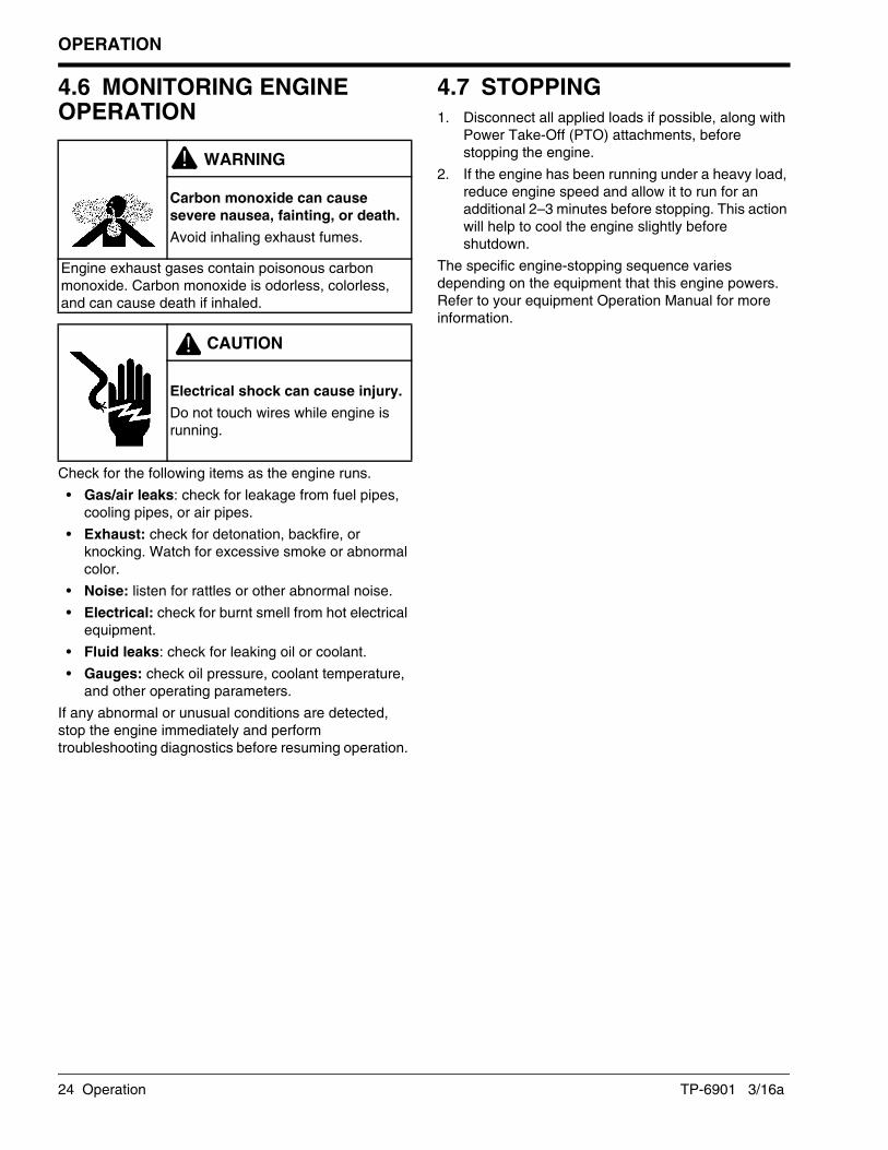
4.6 MONITORING ENGINE OPERATION
Check for the following items as the engine runs.
• Gas/air leaks: check for leakage from fuel pipes, cooling pipes, or air pipes.
• Exhaust: check for detonation, backfire, or knocking. Watch for excessive smoke or abnormal color.
• Noise: listen for rattles or other abnormal noise.
• Electrical: check for burnt smell from hot electrical equipment.
• Fluid leaks: check for leaking oil or coolant.
• Gauges: check oil pressure, coolant temperature, and other operating parameters.
If any abnormal or unusual conditions are detected, stop the engine immediately and perform troubleshooting diagnostics before resuming operation.
4.7 STOPPING1. Disconnect all applied loads if possible, along with
Power Take-Off (PTO) attachments, before stopping the engine.
2. If the engine has been running under a heavy load, reduce engine speed and allow it to run for an additional 2–3 minutes before stopping. This action will help to cool the engine slightly before shutdown.
The specific engine-stopping sequence varies depending on the equipment that this engine powers. Refer to your equipment Operation Manual for more information.
WARNING!Carbon monoxide can cause severe nausea, fainting, or death.
Avoid inhaling exhaust fumes.
Engine exhaust gases contain poisonous carbon monoxide. Carbon monoxide is odorless, colorless, and can cause death if inhaled.
! CAUTION
Electrical shock can cause injury.
Do not touch wires while engine is running.

MAINTENANCE
TP-6901 3/16a Maintenance 25
Section 5 Maintenance
5.1 INTRODUCTIONPreventive maintenance is critical to prolonging the life of the KG2204 and KG2204T engines and keeping them in optimum working condition. As the engine runs, fasteners may loosen, parts may become worn, clearances change, and oil picks up dirt and contaminants. The engine may eventually become hard to start, or may exhibit other symptoms such as decreased power output or increased fuel consumption.
Regularly scheduled maintenance will help to prevent or reduce the impact of these performance issues. Keep the engine working reliably by performing all preventive maintenance tasks described in this section.
WARNING!
Accidental starts can cause severe injury or death.
Disconnect and ground spark plug leads before servicing.
Before working on engine or equipment, disable the engine as follows: 1) Disconnect spark plug leads. 2) Disconnect negative (–) battery cable from battery.
Before disconnecting negative (–) battery cable, make sure all switches are OFF. If ON, a spark will occur at the ground cable terminal which could cause an explosion if hydrogen gas or LPG/NG fuel vapors are present.
WARNING!
Handling caustic engine fluids and chemical products can cause severe chemical burns, nausea, fainting, or death.
Most chemicals such as used engine oil, antifreeze/coolant, rust proofing agent, inhibiting oil, degreasing agent, spray paint, and adhesives are hazardous to health. Read and follow the user information found on the packaging. Avoid inhalation and skin contact. Use only in well-ventilated areas and use a protective mask when spraying. Store engine fluids and chemical products in a locked cabinet. Contact your local recycling center for disposal information and locations.

MAINTENANCE
26 Maintenance TP-6901 3/16a
5.2 FLUID SPECIFICATIONS
Oil Recommendations
NOTE:• Do not mix different brands or types of oil.
• Do not overfill or underfill the engine’s lubrication system. See “Engine Specifications” in Section 8.
Use oil that displays the American Petroleum Institute (API) Starbrust certification mark FOR GASOLINE ENGINES on the container. Do not use straight-weight oils recommended for industrial or stationary engines. CC or CD classification oils, even when labeled HEAVY DUTY or For Natural Gas Engines are not acceptable.
Multi-viscosity synthetic oils are recommended. For best performance in colder environments (such as the United States and Canada), use Society of Automotive Engineers (SAE) 5W-30, API service class SJ or higher. In extremely hot environments where temperatures are never or rarely below 0°C (32°F), use a synthetic oil with a viscosity designation of 10W-30, API service class SJ or higher.
Grease RecommendationsThe alternator and starter bearings on this engine must be lubricated with a high-quality lithium-based automotive grease.
Coolant RecommendationsUse only a mixture of 50% long life coolant and 50% clean, softened water to inhibit rust/corrosion and prevent freezing.
A solution of 50% long life coolant provides freezing protection to –37°C (–34°F) and overheating protections to 149°C (300°F). A coolant solution with less than 50% long life coolant may not provide adequate freezing and overheating protection. Do not mix long life coolants and conventional coolants. Do not mix different types and/or colors of long life coolants.
WARNING!
Explosive fuel can cause fires and severe burns.
If a gaseous odor is detected, ventilate the area and contact an authorized service technician.
LPG (Liquefied Petroleum Gas) is extremely flammable and tends to settle in low areas where a spark or flame could ignite the gas. Do not start or operate this engine in a poorly ventilated area where leaking gas could accumulate and endanger the safety of persons in the area.
NG (Natural Gas) is extremely flammable, is lighter than air, and rises. Do not start or operate this engine in a poorly ventilated are where leaking gas could accumulate and endanger the safety of persons in the area.
To ensure personal safety, installation and repair of LPG/NG fuel supply systems must be performed only by qualified LPG/NG system technicians. Improperly installed and maintained LPG/NG equipment could cause the fuel supply system or other components to malfunction, causing gas leaks.
Observe federal, state, and local laws governing LPG/NG fuel, storage, and systems.

MAINTENANCE
TP-6901 3/16a Maintenance 27
5.3 PERIODIC MAINTENANCE SCHEDULEEngine parts experience wear at different rates. Technical maintenance tasks, therefore, are required at several different intervals throughout the life of the engine:
• Daily
• Weekly or every 10 hours of operation
• Quarterly or every 20 hours of operation
• Yearly or every 120 hours of operation
• 3 Years or every 400/500 hours of operation
• Seasonally
The chart lists the required maintenance tasks at each designated intervals throughout the life of the engine. For example, a task performed after the first 10 hours of operation must be repeated after 20 hours, 30 hours, and so forth.
Daily (before starting)
• Check for loose or missing fasteners. Tighten or replace as needed.
• Check the level of fuel, coolant, and oil. Refill as needed.
• Check coolant system hoses and clamps.
Weekly or every 10 hours of operation
• Check battery connections for tightness and signs of corrosion.
• Check for oil and coolant leaks.
• Check wiring and electrical connections. Repair or replace loose or damaged components.
• Start engine and listen for abnormal noises.
• Check for fuel system leaks, hissing sounds, or gas odor.
Quarterly or every 20 hours of operation
• Check battery voltage; charge or replace as needed.
• Check and clean air filter. (See equipment Operation Manual.)
• Check all fasteners for tightness.
Yearly or every 120 hours of operation
• Check the battery for cracks, damaged electrodes, and corrosion.
• Check the drive-belt tension. Adjust or replace drive belt if necessary.
• Replace engine oil and oil filter.
3 years or every 400 hours of operation
• Change air filter element(s). (See equipment Operation Manual.)
3 years or every 500 hours of operation
• Check spark plug condition and electrode gap. Adjust gap if necessary. Replace spark plug(s) if discolored or damaged.
Seasonal Maintenance
• Check coolant concentration and replenish/replace as needed.
• Replace engine oil with a lower temperature grade in the winter (if required).

MAINTENANCE
28 Maintenance TP-6901 3/16a
5.4 ENGINE
Check Engine OilCheck the engine oil level daily before starting the engine. Inspect the oil for signs of deterioration, discoloration, thinning, or water contamination. If any of these conditions exist, the oil quality has been compromised and should be replaced.
Required materials:• Clean, dry cloth.
• Fresh engine oil. (See “Oil Recommendations” on page 26.)
Procedure:1. Stop the engine and allow it to cool.
Figure 5-1
2. Pull out the oil dipstick (A). See Figure 5-1.
3. Wipe the end of the dipstick with a clean, dry cloth.
4. Insert the dipstick into the engine.
Figure 5-2
5. Pull out the dipstick again to check the oil level. The oil level (B) should be maintained between the F (full) and L (low) marks. See Figure 5-2.
Figure 5-3
6. If the oil level is below L, check for leaks. If no leaks are found, open the oil fill cap (C). Wipe the oil fill cap clean, and add oil up to the F mark. See Figure 5-3.
7. If oil leaks are found, repair them before operating the engine.
Change Engine Oil and Oil FilterChange the engine oil and filter every 120 hours of operation. Replace the engine oil and filter more often if the machine is being run in excessively dirty or dusty conditions.
K0384
A
K0705
B
WARNING!
Handling caustic engine fluids and chemical products can cause severe chemical burns, nausea, fainting, or death.
Most chemicals such as used engine oil, antifreeze/coolant, rust proofing agent, inhibiting oil, degreasing agent, spray paint, and adhesives are hazardous to health. Read and follow the user information found on the packaging. Avoid inhalation and skin contact. Use only in well-ventilated areas and use a protective mask when spraying. Store engine fluids and chemical products in a locked cabinet. Contact your local recycling center for disposal information and locations.
K0384
C

MAINTENANCE
TP-6901 3/16a Maintenance 29
Required materials:• Fresh engine oil (See “Oil Recommendations” on
page 26.)
• Collection container for drained oil—minimum 8 liter (2.1 gal.) capacity
• Replacement oil filter
• Oil filter wrench
• Clean, dry cloth
• Drop cloth to protect work surface
Change the engine oil and oil filter:1. Stop the engine and allow it to cool.
Figure 5-4
2. Place a drop cloth and collection container beneath the oil drain plug (A). See Figure 5-4.
3. Remove the oil drain plug and allow the oil to drain into the container.
WARNING!
Explosive fuel can cause fires and severe burns.
If a gaseous odor is detected, ventilate the area and contact an authorized service technician.
LPG (Liquefied Petroleum Gas) is extremely flammable and tends to settle in low areas where a spark or flame could ignite the gas. Do not start or operate this engine in a poorly ventilated area where leaking gas could accumulate and endanger the safety of persons in the area.
NG (Natural Gas) is extremely flammable, is lighter than air, and rises. Do not start or operate this engine in a poorly ventilated are where leaking gas could accumulate and endanger the safety of persons in the area.
To ensure personal safety, installation and repair of LPG/NG fuel supply systems must be performed only by qualified LPG/NG system technicians. Improperly installed and maintained LPG/NG equipment could cause the fuel supply system or other components to malfunction, causing gas leaks.
Observe federal, state, and local laws governing LPG/NG fuel, storage, and systems.
WARNING!
Hot parts can cause severe burns.
Do not touch engine while operating or just after stopping.
Never operate engine with heat shields or guards removed.
K0405
B
A

MAINTENANCE
30 Maintenance TP-6901 3/16a
Figure 5-5
4. Using an oil filter wrench, remove the old oil filter (D). See Figure 5-5.
NOTE:After removing the oil filter, ensure that the oil cooler adapter nut is tightened to specification, 40 N•m (29.5 ft.lbs.), and that oil cooler adapter and gasket are seated properly.
Figure 5-6
5. Wipe the oil filter installation surface (E) clean with a dry cloth. Inspect the installation surface for damage. See Figure 5-6.
6. Apply a thin film of fresh oil to the gasket of the new oil filter.
Figure 5-7
7. Lightly screw in the new oil filter by hand until you feel resistance. Using the oil filter wrench (F), tighten the filter an additional 3/4 turn, 25 N•m (18.4 ft.lbs.). See Figure 5-7.
8. Install the oil drain plug. Tighten to specification.
Oil Pan Drain Plug Torque
20–25 N•m (14.8–18.4 ft.lb.)
9. Add fresh oil through the oil filler cap (B).
Figure 5-8
10. Check engine oil level, making sure that the level lies between the L and F marks on the dipstick (C). See Figure 5-8.
11. Install and tighten the oil filler cap.
12. Start the engine and run it without load for approximately 5 minutes. This will ensure that the fresh engine oil is distributed to each friction surface.
NOTE:Dispose of used engine oil and oil filters in accordance with local environmental regulations.
K0706
D
K0704
E
K0706
F
K0705
C

MAINTENANCE
TP-6901 3/16a Maintenance 31
Check and Clean the Air FilterRefer to the Equipment Operation Manual using this engine installation.
Replace the Air FilterRefer to the Equipment Operation Manual using this engine installation.
Check and Adjust the Spark PlugsDamaged, loose, or improperly adjusted spark plugs can overheat or cause engine problems such as misfiring, hesitation, or knocking. Check the spark plugs after each 500 hours of operation.
Required materials:• Spark plug wrench
• Torque wrench
• Spark plug gap tool
• Clean, dry cloth
Procedure:1. Stop the engine and allow it to cool.
! CAUTION
Electrical shock can cause injury.
Do not touch wires while engine is running.
WARNING!
Hot parts can cause severe burns.
Do not touch engine while operating or just after stopping.
Never operate engine with heat shields or guards removed.
NOTICE
Label or mark spark plug wires before disconnecting. Spark plug wires MUST be reinstalled in proper order as removed.

MAINTENANCE
32 Maintenance TP-6901 3/16a
Figure 5-9
2. Use a cloth to wipe dirt and oil away from the area around each of the four spark plug wires (A). See Figure 5-9.
3. Disconnect the spark plug wires.
4. Wipe the interior of the spark plug tubes.
5. Use a spark plug wrench to remove the spark plugs.
Figure 5-10
6. Inspect the electrodes (B) on each spark plug. See Figure 5-10. The electrodes should be light brown. If the electrode appears to be burned, covered with soot, or fouled with oil, replace the spark plug.
Figure 5-11
7. Inspect the body of each spark plug for cracks, damage, or discoloration and check that the spark plug O-ring is in good condition. Replace as needed.
8. Use a spark plug gap tool to measure the gap (C) on each spark plug. Adjust the gap to specification. See Figure 5-11.
NOTE:Ensure that the spark plug tubes are seated before installing the spark plugs. If the tubes were removed, reinstall the tubes before installing the spark plugs.
9. Install the spark plugs in the cylinder head.
10. Tighten the spark plugs to specification.
11. Install spark plug wires to spark plugs.
K0384
A
K0703
B
Spark Plug Gap
KG2204 0.9–1.0 mm (0.036–0.040 in.)
KG2204T 0.7–0.8 mm (0.028–0.031 in.)
Spark Plug Torque
KG2204 18 N•m (13.3 ft.lb.)
KG2204T 25 N•m (18.4 ft.lb.)
K0390
C

MAINTENANCE
TP-6901 3/16a Maintenance 33
Replace the Spark PlugsSpark plugs should be replaced at the recommended intervals specified at the beginning of this section. Use only the recommended spark plug or an equivalent. See “Specifications of Main Components” in Section 8.
Required materials:• Replacement spark plugs (4). See Section 8.2 for
spark plug specifications.
• Spark plug wrench
• Spark plug gap tool
• Torque wrench
• Clean, dry cloth
Procedure:1. Stop the engine and allow it to cool.
2. Use a cloth to wipe dirt and oil away from the area around each of the four spark plug wires (A). See Figure 5-12.
3. Disconnect the spark plug wires.
4. Wipe the interior of the spark plug tubes.
5. Use a spark plug wrench to remove the old spark plugs.
Figure 5-12
Figure 5-13
6. Use a spark plug gap tool to measure the gap (B) on each new spark plug. Adjust the gap to specification. See Figure 5-13.
7. Install the new spark plugs in the cylinder head.
8. Tighten the spark plugs to specification.
! CAUTION
Electrical shock can cause injury.
Do not touch wires while engine is running.
WARNING!
Hot parts can cause severe burns.
Do not touch engine while operating or just after stopping.
Never operate engine with heat shields or guards removed.
NOTICE
Label or mark spark plug wires before disconnecting. Spark plug wires MUST be installed in proper order.
Spark Plug Gap
KG2204 0.9–1.0 mm (0.036–0.040 in.)
KG2204T 0.7–0.8 mm (0.028–0.031 in.)
Spark Plug Torque
KG2204 18 N•m (13.3 ft.lb.)
KG2204T 25 N•m (18.4 ft.lb.)
K0384
A
K0390
B

MAINTENANCE
34 Maintenance TP-6901 3/16a
Ignition TimingThe KG2204 and KG2204T engines have an electronic ignition system. All functions of the ignition system, including timing, are controlled by the ECM and cannot be adjusted. Contact your KOHLER authorized distributor/dealer for assistance with ignition-related performance issues.
5.5 ELECTRICAL SYSTEM
Check Battery and ConnectionsCheck the condition of the battery and connections according to the intervals specified in “Periodic Maintenance Schedule” on page 27. Specific items to look for are:
• Loose or missing fasteners on the battery hold-down.
• Loose cable connections.
• Frayed, cut, or broken cables.
• Cracks in battery cell cover or case.
• Dirt, oil, or water contamination.
• Corrosion at battery terminals.
• Reduction in voltage or ability to hold a charge.
Repair or replace the battery and/or components as needed. Use only replacement parts that are equivalent to the original equipment. Contact your KOHLER authorized distributor/dealer for assistance.
Check and Adjust the Drive BeltA worn, stretched, or damaged drive belt may fail, especially under heavy loads. Check the condition of the drive belt regularly and adjust belt tension as needed.
WARNING!Rotating parts can cause severe injury.
Stay away while the engine is in operation.
Keep hands, feet, hair, and clothing away from all moving parts to prevent injury. Never operate the engine with covers, shrouds, or guards removed.

MAINTENANCE
TP-6901 3/16a Maintenance 35
Required materials:• Belt tension gauge or straightedge and steel rule.
Check drive belt condition:1. Stop the engine and allow it to cool.
Figure 5-14
2. Locate the drive belt (A). See Figure 5-14.
Figure 5-15
3. Inspect the drive belt. Look for signs of cracking, separation, cuts, or other damage. See Figure 5-15.
4. If any abnormality is found, replace the drive belt.
Figure 5-16
WARNING!
Accidental starts can cause severe injury or death.
Disconnect and ground spark plug leads before servicing.
Before working on engine or equipment, disable engine as follows: 1) Disconnect spark plug leads. 2) Disconnect negative (–) battery cable from battery.
Before disconnecting negative (–) ground cable, make sure all switches are OFF. If ON, a spark will occur at the ground cable terminal which could cause an explosion if hydrogen gas or LPG/NG fuel vapors are present.
A
K0395
K0707
B
K0395
MAINTENANCE
36 Maintenance TP-6901 3/16a
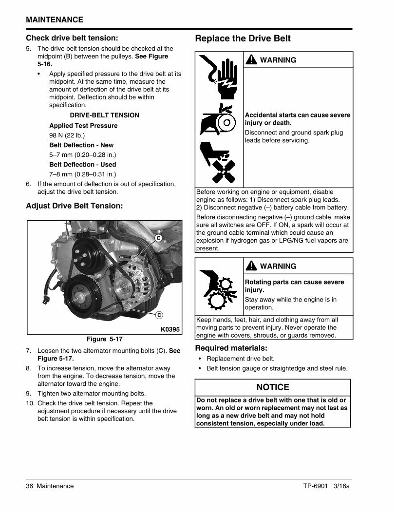
Check drive belt tension:5. The drive belt tension should be checked at the
midpoint (B) between the pulleys. See Figure 5-16.
• Apply specified pressure to the drive belt at its midpoint. At the same time, measure the amount of deflection of the drive belt at its midpoint. Deflection should be within specification.
DRIVE-BELT TENSION
Applied Test Pressure
98 N (22 lb.)
Belt Deflection - New
5–7 mm (0.20–0.28 in.)
Belt Deflection - Used
7–8 mm (0.28–0.31 in.)
6. If the amount of deflection is out of specification, adjust the drive belt tension.
Adjust Drive Belt Tension:
Figure 5-17
7. Loosen the two alternator mounting bolts (C). See Figure 5-17.
8. To increase tension, move the alternator away from the engine. To decrease tension, move the alternator toward the engine.
9. Tighten two alternator mounting bolts.
10. Check the drive belt tension. Repeat the adjustment procedure if necessary until the drive belt tension is within specification.
Replace the Drive Belt
Required materials:• Replacement drive belt.
• Belt tension gauge or straightedge and steel rule.
C
C
K0395
WARNING!
Accidental starts can cause severe injury or death.
Disconnect and ground spark plug leads before servicing.
Before working on engine or equipment, disable engine as follows: 1) Disconnect spark plug leads. 2) Disconnect negative (–) battery cable from battery.
Before disconnecting negative (–) ground cable, make sure all switches are OFF. If ON, a spark will occur at the ground cable terminal which could cause an explosion if hydrogen gas or LPG/NG fuel vapors are present.
WARNING!Rotating parts can cause severe injury.
Stay away while the engine is in operation.
Keep hands, feet, hair, and clothing away from all moving parts to prevent injury. Never operate the engine with covers, shrouds, or guards removed.
NOTICE
Do not replace a drive belt with one that is old or worn. An old or worn replacement may not last as long as a new drive belt and may not hold consistent tension, especially under load.

MAINTENANCE
TP-6901 3/16a Maintenance 37
Figure 5-18
1. Loosen the two alternator mounting bolts (A) on the alternator and mounting bracket. See Figure 5-18.
2. Remove and discard the old drive belt.
Figure 5-19
3. Place the new drive belt on the pulleys. Make sure that the belt is properly aligned with the grooves on each pulley. See Figure 5-19.
Figure 5-20
4. Set drive belt tension to specification. See Figure 5-20.
• Apply specified pressure to the drive belt at its midpoint. At the same time, measure the amount of deflection of the drive belt at its midpoint (D). Deflection should be within specification.
DRIVE BELT TENSION
Applied Test Pressure
98 N (22 lb.)
Belt Deflection - New
5–7 mm (0.20–0.28 in.)
Belt Deflection - Used
7–8 mm (0.28–0.31 in.)
5. Tighten the two alternator mounting bolts.
6. Check the drive belt tension and adjust the alternator position as needed until correct drive belt tension is reached.
Check Wiring and Electrical Connections
Check the condition of the wiring and electrical connections after every 10 hours of operation. Specific items to look for are:
• Exposed (bare) wires.
• Cuts or abrasions in wire insulation.
• Loose connections at screw terminals.
• Loose, dirty, or cracked electrical connectors.
• Melted or scorched wiring, insulation, or connectors.
Repair or replace faulty electrical components before operating the machine.
B Correct C Incorrect
A
A
K0395
CB
K0708
D
K0395
! CAUTION
Electrical shock can cause injury.
Do not touch wires while engine is running.

MAINTENANCE
38 Maintenance TP-6901 3/16a
5.6 COOLING SYSTEM
Check Coolant Level and ConditionThe engine coolant level should be checked daily before starting the engine. Insufficient coolant will cause the engine to overheat.
Check coolant level:1. Open the radiator cap slowly in order to release the
pressure in the system.
2. Maintain the coolant level in the coolant overflow bottle between the High and Low markings. See “Coolant Recommendations” on page 26.
NOTE:Periodically check the coolant level by removing the radiator’s pressure cap. Do not rely solely on the level in the coolant overflow bottle.
3. Install and tighten the radiator cap.
Check coolant condition:Engine coolant should be uniformly colored and transparent. Replace the coolant if it is dirty, discolored, or fouled with oil or rust particles.
Rusty coolant may indicate corrosion inside the radiator. Oil in the coolant indicates a leak somewhere in the lubrication system. Contact a KOHLER authorized distributor/dealer if either of these conditions exist.
Check Hoses and ClampsCheck the condition of the coolant system hoses and clamps every 10 hours of operation.
Hoses:• Inspect the hoses for cracks, abrasions, cuts,
bulges, swollen ends, or leaks.
• Squeeze the hoses. They should yield slightly to moderate pressure and not feel too hard, too soft, or spongy.
• Replace faulty hoses before operating the engine.
Clamps:• Verify that all clamps are in place.
• Adjust and tighten clamps as needed.
WARNING!
Hot coolant and steam. Can cause severe injury or death.
Before removing the pressure cap, stop the engine and allow it to cool. Then loosen the pressure cap to relieve pressure.

MAINTENANCE
TP-6901 3/16a Maintenance 39
5.7 FUEL SYSTEM
NOTE:Fuel system components are not adjustable and cannot be serviced. Contact your authorized KOHLER authorized distributor/dealer for replacements.
Check Fuel Supply Pipe and ConnectionsWith the fuel valve fully opened and the engine stopped, check all fuel system connections and lines for leaks using a soapy water solution. Correct any leaks before restarting the engine. Do not start the engine if you can smell leaking gas. Have any necessary service performed by a KOHLER authorized distributor/dealer or qualified LPG/NG technician only.
Check Fuel Level (LPG only)With the fuel valve on the LPG tank fully closed and the engine stopped, check the fuel gauge on the LPG tank. Make sure that the tank contains enough fuel for sustained operation. If not, refill the tank before restarting the engine.
Fully open the fuel valve on the LPG tank. Check all fuel supply connections and lines for leaks using a soapy water solution. Correct any leaks before restarting the engine. Have any necessary service performed by a KOHLER authorized distributor/dealer or qualified LPG/NG technician only.
WARNING!
Explosive fuel can cause fires and severe burns.
If a gaseous odor is detected, ventilate the area and contact an authorized service technician.
LPG (Liquefied Petroleum Gas) is extremely flammable and tends to settle in low areas where a spark or flame could ignite the gas. Do not start or operate this engine in a poorly ventilated area where leaking gas could accumulate and endanger the safety of persons in the area.
NG (Natural Gas) is extremely flammable, is lighter than air, and rises. Do not start or operate this engine in a poorly ventilated are where leaking gas could accumulate and endanger the safety of persons in the area.
To ensure personal safety, installation and repair of LPG/NG fuel supply systems must be performed only by qualified LPG/NG system technicians. Improperly installed and maintained LPG/NG equipment could cause the fuel supply system or other components to malfunction, causing gas leaks.
Observe federal, state, and local laws governing LPG/NG fuel, storage, and systems.

MAINTENANCE
40 Maintenance TP-6901 3/16a

TROUBLESHOOTING
TP-6901 3/16a Troubleshooting 41
Section 6 Troubleshooting
6.1 INTRODUCTIONThe following chart will help you to identify and solve some of the basic operating problems that may occur while operating this engine.
Do not attempt to service or replace major engine components, or any items that require special timing or adjustment procedures. This work should be performed only by a KOHLER authorized distributor/dealer.
6.2 TROUBLESHOOTING
Problem Possible Cause Solution
Will Not Start No fuel Check fuel supply.
Incorrect fuel Make sure fuel system is configured
properly for LPG or NG supply.
Dirty/restricted fuel system Check fuel system and clean
components as needed.
Incorrect oil level Check engine oil level; add as needed.
Engine overloaded Disconnect or reduce loads.
Faulty spark plug Inspect, adjust, or replace as needed.
Hard Starting No fuel Check fuel supply.
Incorrect fuel Make sure fuel system is configured
properly for LPG or NG supply.
Restricted fuel flow Make sure fuel supply valves are open;
check for air intake system leakage.
Dirty/restricted fuel system Check fuel system and clean
components as needed.
Incorrect oil level Check engine oil level; add as needed.
Engine overloaded Disconnect or reduce loads.
Faulty spark plug Inspect, adjust, or replace as needed.
Stops Suddenly No fuel Check fuel supply.
Dirty/restricted fuel system Check fuel system and clean
components as needed.
Incorrect oil level Check engine oil level; add as needed.
Engine overloaded Disconnect or reduce loads.
Lacks Power Incorrect fuel Make sure fuel system is configured
properly for LPG or NG supply.
Low fuel pressure Check and adjust fuel pressure.
Incorrect oil level Check engine oil level; add as needed.
Engine overloaded Disconnect or reduce loads.
Faulty spark plug Inspect, adjust, or replace as needed.
Dirty/restricted fuel system Check fuel system and clean
components as needed.

TROUBLESHOOTING
42 Troubleshooting TP-6901 3/16a
Operates Erratically or Unevenly Incorrect fuel Make sure fuel system is configured
properly for LPG or NG supply.
Dirty/restricted fuel system Check fuel system and clean
components as needed.
Low fuel supply pressure Check and adjust.
Engine overloaded Disconnect or reduce loads.
Loose wiring at shut-off valve(s) Check wiring and repair connections.
Faulty spark plug Inspect, adjust, or replace as needed.
Dirty air filter Inspect and replace as needed.
Knocks or Pings Incorrect fuel Make sure fuel system is configured
properly for LPG or NG supply.
Engine overloaded Disconnect or reduce loads.
Faulty spark plug Inspect, adjust, or replace as needed.
Dirty/restricted fuel system Check fuel system and clean
components as needed.
Dirty air filter Inspect and replace as needed.
Skips or Misfires Incorrect fuel Make sure fuel system is configured
properly for LPG or NG supply.
Faulty spark plug Inspect, adjust, or replace as needed.
Dirty/restricted fuel system Check fuel system and clean
components as needed.
Dirty air filter Inspect and replace as needed.
Backfires Incorrect fuel Make sure fuel system is configured
properly for LPG or NG supply.
Faulty spark plug Inspect, adjust, or replace as needed.
Dirty/restricted fuel system Check fuel system and clean
components as needed.
Dirty air filter Inspect and replace as needed.
Overheats Incorrect fuel Make sure fuel system is configured
properly for LPG or NG supply.
Dirty/restricted fuel system Check fuel system and clean
components as needed.
Incorrect oil level Check engine oil level; add as needed.
Engine overloaded Disconnect or reduce loads.
Faulty spark plug Inspect, adjust, or replace as needed.
Consumes Excess Fuel Faulty spark plug Inspect, adjust, or replace as needed.
Dirty/restricted air cleaner element Clean or replace.
Incorrect fuel pressure Check and adjust fuel pressure.
ECM Does Not Store DTC Faulty electrical connections, components, or wiring
Contact KOHLER service.
Knocks or Pings Boost pressure too high Check for stuck wastegate, check for leak in wastegate boost line.
Excessive intake manifold temperature Check charge air cooler for debris and clean as needed.
Lacks power Air induction system leak Inspect air induction system.
Damaged turbocharger Inspect turbocharger compressor and turbine blades for damage and/or contact against housing.
Erratic operation Air induction system leak Inspect air induction system.
Problem Possible Cause Solution

STORAGE
TP-6901 3/16a Storage 43
Section 7 Storage
7.1 PREPARATIONIf you plan to take the engine out of service for an extended period of time, prepare the engine according to the tasks described in this section. These preventive measures will help to protect your engine from the cumulative effects of rust and deterioration while it is not being used.
• Perform scheduled periodic maintenance tasks.
• Make all necessary repairs and adjustments.
• Close the fuel valves and disconnect the fuel supply.
• Clean the outside of the engine. Wipe away all visible dirt, dust, and oil.
• Remove the starting key.
7.2 SHORT-TERM STORAGE (LESS THAN 30 DAYS)• Disconnect and remove the battery.
• Cover or cap all intake and exhaust ports, including fuel lines, air filter, and engine exhaust.
• Cover the engine with a clean, dry cloth.
• Store the engine in a secure, dry location away from trespassers, children, and animals.
7.3 LONG-TERM STORAGE (MORE THAN 30 DAYS)In addition to the short-term tasks listed above, perform these additional tasks before placing the engine in storage:
• Change the engine oil and filter.
• Loosen the drive belt.
• Protect the cylinders from rust:
— Disconnect the spark plug wires and remove the spark plugs.
— Squirt approximately 30 ml (1 ounce) of fresh engine oil into each cylinder.
— Manually rotate the crankshaft 10–15 times to distribute the oil evenly in the cylinders.
— Install the spark plugs and reconnect the spark plug wires.
• Cover all exposed metal parts with a suitable protectant.
• Coat all electrical connectors with a suitable protectant.
7.4 MAINTENANCE WHILE IN STORAGE
• Inspect the engine regularly (at least once a month). Check for signs of rust or leaks.
• Periodically test the battery voltage and recharge as needed. The battery may lose charge even when disconnected.
! CAUTION
Electrical shock can cause injury.
Do not touch wires while engine is running.
WARNING!
Handling caustic engine fluids and chemical products can cause severe chemical burns, nausea, fainting, or death.
Most chemicals such as used engine oil, antifreeze/coolant, rust proofing agent, inhibiting oil, degreasing agent, spray paint, and adhesives are hazardous to health. Read and follow the user information found on the packaging. Avoid inhalation and skin contact. Use only in well-ventilated areas and use a protective mask when spraying. Store engine fluids and chemical products in a locked cabinet. Contact your local recycling center for disposal information and locations.

STORAGE
44 Storage TP-6901 3/16a
7.5 REMOVAL FROM STORAGE
• Remove protective cloths, covers, and caps from the engine.
• Clean protectant from exposed metal parts and electrical components.
• Tighten the alternator belt.
• Check fluid levels and fill as needed.
• Connect the battery.
• Connect the fuel supply and open fuel valves.
• Start the engine and allow it to run for several minutes without load. Check for leaks and watch for signs of abnormal operation.
NOTE:T
The engine may smoke when started for the first time after being taken out of storage. This is normal and occurs as the engine burns away the protective oil coating inside the cylinders.
• Check oil pressure and fuel pressure gauges to make sure that the engine is operating normally.

SPECIFICATIONS
TP-6901 3/16a Specifications 45
Section 8 Specifications
8.1 ENGINE SPECIFICATIONS
Item Specifications
Engine Model KG2204 KG2204T
Block Type I-4
Number of Cylinders 4
Cylinder Bore 91 mm (3.5 in.)
Piston Stroke 86 mm (3.4 in.)
Displacement 2.2 L (134.25 in.3)
Rated Output 30 kW (40 HP) @ 1800 rpm 47.8 kW (64.1 HP) @ 1800 rpm
Fuel Type Propane, Liquid Petroleum Gas (LPG) or Natural Gas (NG). See “Fuel Specifications” in Section 4.
Oil Type / Weight KOHLER synthetic engine oil, SAE Class SJ or higher. Variable per ambient temperature. See “Oil Recommendations” in Section 5.
Oil Dry Fill Capacity 4.2 L (4.4 qt.)
Rotating Direction of Crankshaft Counterclockwise (face to flywheel)
Compression Ratio 10.5:1
Cylinder Fire Order 1-3-4-2
Lubricating Style Pressurized
Starting Style Electric
Net Weight (Dry) 145 kg (320 lb.)
Overall Dimensions (L x W x H) 826 x 547 x 647 mm (32.5 x 21.5 x 25.5 in.)
Aspiration Natural Turbocharged
Charge Air Cooler NA Aluminum core

SPECIFICATIONS
46 Specifications TP-6901 3/16a
8.2 SPECIFICATIONS OF MAIN COMPONENTS
8.3 ADJUSTMENT SPECIFICATIONS
8.4 TORQUE SPECIFICATIONS
Item
Specifications
KG2204 KG2204T
Oil Filter/ Breather Paper, Rocker Arm Covers, Top Oil Filter
Oil Pump Rotor type
Water Pump Centrifugal type; no fan
Flywheel Flywheel with attachment provisions for flywheel adapter (KOHLER part number GM88832)
Thermostat Settings Valve open at 76°C (169°F)Valve lift fully open at 88°C (190°F)
Alternator Rated voltage 14 V, rated current 90 A
Electric Starter 1.2 kW, speed reduction type
Ignition System Electronic
Spark Plug GM92785 (KG2204 only)Screw thread M14 x 1.25
GM100158 (use only genuine Kohler service parts)
Item
Specifications
KG2204 KG2204T
Spark Plug Gap 0.9–1.0 mm (0.036–0.040 in.) 0.7–0.8 mm (0.028–0.030 in.)
Drive Belt Tension at pressure of 98 N (22 lb)
Deflection of a new belt is 5–7 mm (0.20–0.28 in.)Deflection of a used belt is 7–8 mm (0.28–0.31 in.)
Fuel Pressure Regulator Nonadjustable, LPG or NG selectable
Throttle Nonadjustable, ECM controlled
Air–Fuel Mixer Tamper-proof; nonadjustable
Fuel Control Valve Nonadjustable
Item N•m ft.lb.
Spark Plugs - KG2204 18 13.3
Spark Plugs - KG2204T 25 18.4
Oil Drain Plug 20–25 14.8–18.4

SPECIFICATIONS
TP-6901 3/16a Specifications 47
8.5 STANDARD TORQUE SPECIFICATIONS
NOTE:1. The torque values above are general guidelines. Always use the torque values specified in the service
manuals and/or assembly drawings when they differ from above torque values.
2. The torque values above are based on new plated threads. Increase torque values by 15% if non-plated threads are used.
3. Hardware threaded into aluminum must have either two diameters of thread engagement or a 30% or more reduction in the torque to prevent stripped threads.
4. Torque values are calculated as equivalent stress loading on American hardware with an approximate preload of 90% of the yield strength and a friction coefficient of 0.125.
American Standard Fasteners Torque Specifications
SizeTorque
Measurement
Assembled into Cast Iron or Steel Assembled into Aluminum Grade
2 or 5Grade 2 Grade 5 Grade 8
8-32 N•m (in.lb.) 1.8 (16) 2.3 (20) —
See Note 3
10-24 N•m (in.lb.) 2.9 (26) 3.6 (32) —
10-32 N•m (in.lb.) 2.9 (26) 3.6 (32) —
1/4-20 N•m (in.lb.) 6.8 (60) 10.8 (96) 14.9 (132)
1/4-28 N•m (in.lb.) 8.1 (72)) 12.2 (108) 16.3 (144)
5/16-18 N•m (in.lb.) 13.6 (120) 21.7 (192) 29.8 (264)
5/16-24 N•m (in.lb.) 14.9 (132) 23.1 (204) 32.5 (288)
3/8-16 N•m (ft.lb.) 24.0 (18) 38.0 (28) 53.0 (39)
3/8-24 N•m (ft.lb.) 27.0 (20) 42.0 (31) 60.0 (44)
7/16-14 N•m (ft.lb.) 39.0 (29) 60.0 (44) 85.0 (63)
7/16-20 N•m (ft.lb.) 43.0 (32) 68.0 (50) 95.0 (70)
1/2-13 N•m (ft.lb.) 60.0 (44) 92.0 (68) 130.0 (96)
1/2-20 N•m (ft.lb.) 66.0 (49) 103.0 (76) 146.0 (108)
9/16-12 N•m (ft.lb.) 81.0 (60) 133.0 (98) 187.0 (138)
9/16-18 N•m (ft.lb.) 91.0 (67) 148.0 (109) 209.0 (154)
5/8-11 N•m (ft.lb.) 113.0 (83) 183.0 (135) 259.0 (191)
5/8-18 N•m (ft.lb.) 128.0 (94) 208.0 (153) 293.0 (216)
3/4-10 N•m (ft.lb.) 199.0 (147) 325.0 (240) 458.0 (338)
3/4-16 N•m (ft.lb.) 222.0 (164) 363.0 (268) 513.0 (378)
1-8 N•m (ft.lb.) 259.0 (191) 721.0 (532) 1109.0 (818)
1-12 N•m (ft.lb.) 283.0 (209) 789.0 (582) 1214.0 (895)

SPECIFICATIONS
48 Specifications TP-6901 3/16a
NOTE:1. The torque values above are general guidelines. Always use the torque values specified in the service
manuals and/or assembly drawings when they differ from above torque values.
2. The torque values above are based on new plated threads. Increase torque values by 15% if non-plated threads are used.
3. Hardware threaded into aluminum must have either two diameters of thread engagement or a 30% or more reduction in the torque to prevent stripped threads.
4. Torque values are calculated as equivalent stress loading on American hardware with an approximate preload of 90% of the yield strength and a friction coefficient of 0.125.
Metric Fasteners Torque Specifications
SizeTorque
Measurement
Assembled into Cast Iron or Steel Assembled into Aluminum Grade
5.8 or 8.8Grade 5.8 Grade 8.8 Grade 10.9
M6 x 1.00 N•m (ft.lb.) 6.2 (4.6) 12 (9) 13.6 (10)
See Note 3
M8 x 1.25 N•m (ft.lb.) 15.0 (11) 29.6 (22) 33.0 (24)
M8 x 1.00 N•m (ft.lb.) 16.0 (11) 24.0 (18) 34.0 (25)
M10 x 1.50 N•m (ft.lb.) 30.0 (22) 52.5 (39) 65.0 (48)
M10 x 1.25 N•m (ft.lb.) 31.0 (23) 47.0 (35) 68.0 (50)
M12 x 1.75 N•m (ft.lb.) 53.0 (39) 80.0 (59) 115.0 (85)
M12 x 1.50 N•m (ft.lb.) 56.0 (41) 85.0 (63) 122.0 (90)
M14 x 2.00 N•m (ft.lb.) 83.0 (61) 135.0 (100) 180.0 (133)
M14 x 1.50 N•m (ft.lb.) 87.0 (64) 133.0 (98) 190.0 (140)
M16 x 2.00 N•m (ft.lb.) 127.0 (94) 194.0 (143) 278.0 (205)
M16 x 1.50 N•m (ft.lb.) 132.0 (97) 201.0 (148) 287.0 (212)
M18 x 2.50 N•m (ft.lb.) 179.0 (132) 273.0 (201) 390.0 (288)
M18 x 1.50 N•m (ft.lb.) 189.0 (140) 289.0 (213) 413.0 (305)

Notes
NOTES


TP-6901 3/16a®
Kohler Power SystemsAsia Pacific Headquarters7 Jurong Pier RoadSingapore 619159Phone (65) 6264-6422, Fax (65) 6244-6455 2014, 2016 by Kohler Co. All Rights Reserved.
Kohler CO. Kohler, Wisconsin 53044Phone 920-457-4441, Fax 920-459-1646For the nearest sales/service outlet in theUS and Canada, phone 1-800-544-2444KOHLERPower.com