Embed Size (px)
Citation preview

SHORT INSTRUCTIONS FOR OPERATING SD2 AT CIAN Version 6, September 2015
General workflow
1. Turn on microscope, components as needed (see sections 1, 2) 2. Start up computer, log into one of the acquisition software:
o Volocity (see section 3.2) o Metamorph (see section 3.3)
3. Visually inspect objectives; clean as needed (section 2.2) 4. Use test slide to adjust Köhler illumination in bright field (section 2.1) 5. Focus and position experimental sample in transmitted light (section 3.1) 6. Use acquisition software to acquire images (section 3.2, or 3.3) 7. When done, send light to eyepiece, clean microscope workstation as needed 8. Turn off microscope (see section 4) 9. Move data off computer (see section 5), log out of computer
General reminders for SD2
• Save the camera: move light to eyepiece when not acquiring data; avoid overexposure by checking intensity levels
• Optical cables are fragile, don’t touch or put things on them • Avoid bumping into equipment, leaning on air table • Keep immersion oil bottle tightly closed – except when actively using – to avoid
spills • Only use cover slips of “no. 1.5” thickness (0.17 mm) • Keep objective variable NA ring all the way open (clockwise) • Move data off microscope computer – if storage space runs out during an
acquisition, all data is lost for that acquisition! • Limit or omit use of non-confocal (wide field) fluorescence to save sample, signal • Acquisition software time = pay time; log off when not needed
Useful abbreviations and terms SD = spinning disk BF = bright field TL = transmitted light IL = incident light, i.e. fluorescent light AP = aperture diaphragm (also FA = field
aperture) FD = field diaphragm WFF = wide field fluorescence
DIC = Differential Interference Contrast, a.k.a. Nomarski Interference Contrast
FRAP = fluorescence recovery after photobleaching
Volocity = acquisition and analysis software from Improvision (Perkin-Elmer)
MetaMorph = acquisition and analysis software from Molecular Devices
Light sources on SD2: halogen lamp (for TL), Exfo metal halide lamp (for WFF), lasers (for SD confocal), and the Mosaic laser for photo-manipulation (e.g. FRAP applications).
CIAN SD2 – short instructions, version 6, September 2015 page 2 of 12
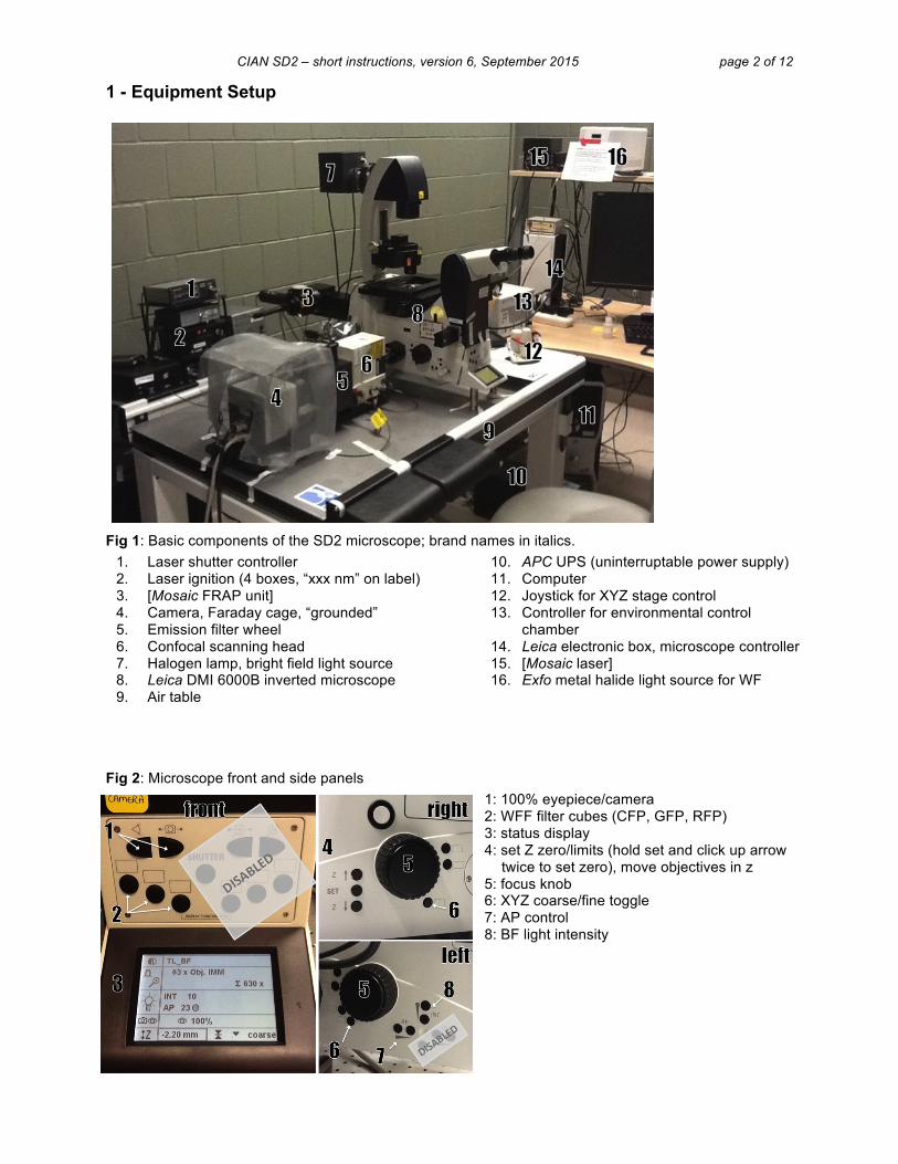
1 - Equipment Setup
Fig 1: Basic components of the SD2 microscope; brand names in italics. 1. Laser shutter controller 2. Laser ignition (4 boxes, “xxx nm” on label) 3. [Mosaic FRAP unit] 4. Camera, Faraday cage, “grounded” 5. Emission filter wheel 6. Confocal scanning head 7. Halogen lamp, bright field light source 8. Leica DMI 6000B inverted microscope 9. Air table
10. APC UPS (uninterruptable power supply) 11. Computer 12. Joystick for XYZ stage control 13. Controller for environmental control
chamber 14. Leica electronic box, microscope controller 15. [Mosaic laser] 16. Exfo metal halide light source for WF
Fig 2: Microscope front and side panels 1: 100% eyepiece/camera 2: WFF filter cubes (CFP, GFP, RFP) 3: status display 4: set Z zero/limits (hold set and click up arrow
twice to set zero), move objectives in z 5: focus knob 6: XYZ coarse/fine toggle 7: AP control 8: BF light intensity
CIAN SD2 – short instructions, version 6, September 2015 page 3 of 12
2 - Starting up SD2 Note: Diode lasers and Exfo lamp require only minimal warm up, but adhere to 15min/15min rule: leave on at least 15 min before shutting off, leave off at least 15 min before restarting 1. Take the dust cover off the microscope, put on hooks by the door, not the floor 2. Remove any stage inserts, CO2 chamber, objective warmer to make sure that the stage does not hit
anything when moving on startup 3. Turn on laser shutter control box (Fig 1-1) 4. Turn on microscope system by pressing the top button on the APC UPS (Fig 1-10) 5. Turn on computer (Fig 1-11), log in to your account, start acquisition software; in Volocity, calibrate
stage (‘Stage : Calibrate Stage’) 6. Optional, as needed: turn on lasers (Fig 1-2), Exfo widefield fluorescent light source (Fig 1-16),
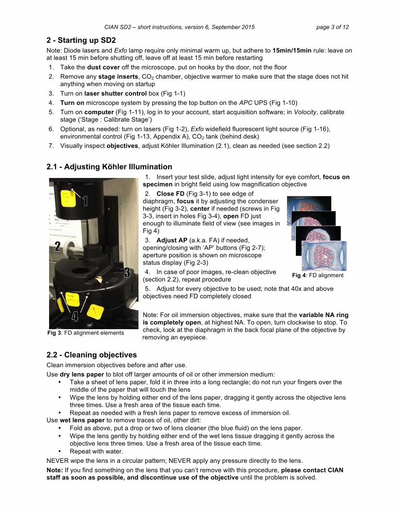
environmental control (Fig 1-13, Appendix A), CO2 tank (behind desk) 7. Visually inspect objectives, adjust Köhler Illumination (2.1), clean as needed (see section 2.2) 2.1 - Adjusting Köhler Illumination
1. Insert your test slide, adjust light intensity for eye comfort, focus on specimen in bright field using low magnification objective 2. Close FD (Fig 3-1) to see edge of
diaphragm, focus it by adjusting the condenser height (Fig 3-2), center if needed (screws in Fig 3-3, insert in holes Fig 3-4), open FD just enough to illuminate field of view (see images in Fig 4) 3. Adjust AP (a.k.a. FA) if needed,
opening/closing with ‘AP’ buttons (Fig 2-7); aperture position is shown on microscope status display (Fig 2-3) 4. In case of poor images, re-clean objective
(section 2.2), repeat procedure 5. Adjust for every objective to be used; note that 40x and above
objectives need FD completely closed Note: For oil immersion objectives, make sure that the variable NA ring is completely open, at highest NA. To open, turn clockwise to stop. To check, look at the diaphragm in the back focal plane of the objective by removing an eyepiece.
2.2 - Cleaning objectives Clean immersion objectives before and after use. Use dry lens paper to blot off larger amounts of oil or other immersion medium:
• Take a sheet of lens paper, fold it in three into a long rectangle; do not run your fingers over the middle of the paper that will touch the lens
• Wipe the lens by holding either end of the lens paper, dragging it gently across the objective lens three times. Use a fresh area of the tissue each time.
• Repeat as needed with a fresh lens paper to remove excess of immersion oil. Use wet lens paper to remove traces of oil, other dirt:
• Fold as above, put a drop or two of lens cleaner (the blue fluid) on the lens paper. • Wipe the lens gently by holding either end of the wet lens tissue dragging it gently across the
objective lens three times. Use a fresh area of the tissue each time. • Repeat with water.
NEVER wipe the lens in a circular pattern; NEVER apply any pressure directly to the lens. Note: If you find something on the lens that you can’t remove with this procedure, please contact CIAN staff as soon as possible, and discontinue use of the objective until the problem is solved.
Fig 3: FD alignment elements
Fig 4: FD alignment
CIAN SD2 – short instructions, version 6, September 2015 page 4 of 12
3 - Operating SD2 - Report any problems to facility staff (on PPMS, by email, in person)
3.1 - Manual controls (some disabled for safety reasons) See Fig 2 for layout of buttons on microscope body. Most functions are also available as software controls in Volocity or Metamorph.
Fig 5: Leica XYZ joystick 1: focus/Z control 2: Y control 3: X control 4: XY fine (top) and coarse (bottom) 5: Z fine (top) and coarse (bottom)
(The fine/coarse movement for all three dimensions, XYZ, can be toggled using one of the buttons on the side of the microscope, Fig 2-6.)
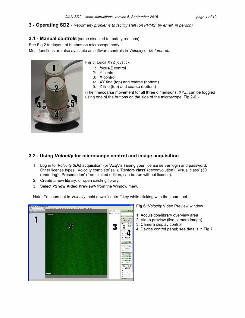
3.2 - Using Volocity for microscope control and image acquisition
1. Log in to ‘Volocity 3DM acquisition’ (or ‘AcqVis’) using your license server login and password. Other license types: ‘Volocity complete’ (all), ‘Restore class’ (deconvolution), ‘Visual class’ (3D rendering), ‘Presentation’ (free, limited edition, can be run without license).
2. Create a new library, or open existing library. 3. Select <Show Video Preview> from the Window menu.
Note: To zoom out in Volocity, hold down “control” key while clicking with the zoom tool.
Fig 6: Volocity Video Preview window 1: Acquisition/library overview area 2: Video preview (live camera image) 3: Camera display control 4: Device control panel; see details in Fig 7

CIAN SD2 – short instructions, version 6, September 2015 page 5 of 12
Fig 7: Device controls in Video Preview window; will change dependent on settings
< Time or elapsed time, toggle through views by clicking on panel
< hard disk storage space
< Pixel intensity min. and max. – can toggle to different views of signal intensity, e.g. signal/time graph for bleaching evaluation
< Acquisition rate/frequency – pull down to select for manual control
< Acquisition setup – double-click to see menu (see section 3.2.2)
Shoot – click to shoot a single image, Acquire – start recording with current settings (turns into stop button, Pause and Mark Event will become available), Freeze preview and close shutter
< Button to save light path changes Confocal, WFF, TL shutters
< Exposure time < Auto exposure (use with caution)
< Auto contrast (use recommended)
< Camera sensitivity
< Laser line indicator (do not use to switch laser lines)
< Laser intensity control (neutral density filters) – linear between 20 and 80%
< Confocal emission filter indicator – should match light path
Focus controls, Leica focus drive < Leica controller will be used for Z stack setup; use button in circle
to pull up the focus control window (see section 3.2.1) < XY stage position indicator
< switch light between camera (“left”) and eyepiece (use this OR buttons on microscope body)
Light path manager many light paths are preconfigured, save changes by clicking button in ‘O’, specific configurations can be made upon request • CFP, GFP, YFP, RFP, FRFP
confocal • BF, bright field • DIC • POL, polarization • WFF, wide field fluorescence; not
false colored

CIAN SD2 – short instructions, version 6, September 2015 page 6 of 12
3.2.1. Z-stack setup 1. focus on the sample in Video Preview 2. click on the Leica focus control button (highlighted in Fig 7) to open control
window (Fig 8); slider arrow on the right can be used to control Z position 3. [optional: choose <Set Zero> to set current position as 0µm] 4. for stack definition:
a. find the top/bottom of the sample, click <Set Top>/<Set Bottom> b. alternatively, enter relative distances from current position in the up/down
arrow fields, e.g. ‘5’ and ‘-5’ for a 10µm stack around zero, or enter stack size when position is zeroed for even stack around current position
3.2.2. Acquisition protocol setup Remember to balance laser power vs. bleaching, exposure time vs. dynamics; set gain accordingly, avoiding constant use of 100% gain. 1. Open Acquisition Setup window by double-clicking
green rectangle in device control panel (Fig 7, boxed) 2. Select the channel(s) for acquisition 3. For Z-stack acquisition, select Leica stage, then choose
one of: • Capture using Z spacing • Capture this many slices
4. Specify the order for channels and Z stacks 5. Shutter management – “balanced” usually works well 6. Time: Setup the duration and frequency of capture 7. Points: For multiple XY positions, select ‘Leica XY
stage’, set up as in 3.2.3 8. Other tabs: ‘Stitch’ for tiling images across an area larger than the field of view
(avoid stitching the images during acquisition); ‘Reference’ allows to exclude one channel from Z stack, e.g. BF or DIC, capturing only one slice; refer to user manual for more information on the other options
Save acquisition settings using a descriptive name (‘save as – export’, e.g. to Desktop) for future use with “Restore”, or click OK to use immediately. 3.2.3 Multi-point acquisition Change to stage view by right clicking into preview, checking ‘XY stage’ 1. Make sure that stage calibration was done before any stage inserts
were put in place, ‘Stage : Calibrate’ 2. Clear all points if needed (program remembers last set of points) 3. Find an XY(Z) position of interest using Video Preview, save position
with ‘Stage : Add A Point’ [XY points can’t be modified, but have to be removed and re-added; to remove a point, select a region of interest around point, then do ‘Stage : Clear Selected Point’]
4. Keep track of point placement by sketching a map on a piece of paper 5. When all points are set, recheck focus by one of two methods:
– All points sequentially: ‘Stage : Review Points’; for each point, adjust focus, click ‘next’ – Points individually: ‘Stage : Go to next point’, adjust focus, click ‘update point’, repeat
6. Before starting the acquisition, quit and relaunch Volocity to save points, or save under a descriptive name using ‘Stage : Save Points’
Fig 8
Fig 9: Acquisition Setup window
Fig 10: XY Stage View, with video preview inset
CIAN SD2 – short instructions, version 6, September 2015 page 7 of 12
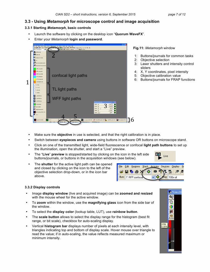
3.3 - Using Metamorph for microscope control and image acquisition 3.3.1 Starting Metamorph, basic controls
• Launch the software by clicking on the desktop icon “Quorum WaveFX”. • Enter your Metamorph login and password.
• Make sure the objective in use is selected, and that the right calibration is in place. • Switch between eyepieces and camera using buttons in software OR buttons on microscope stand. • Click on one of the transmitted light, wide-field fluorescence or confocal light path buttons to set up
the illumination, open the shutter, and start a “Live” preview. • The “Live” preview is stopped/started by clicking on the icon in the left side
buttons/journals, or buttons in the acquisition windows (see below).
• The shutter for the active light path can be opened and closed by clicking on the icon to the left of the objective selection drop-down, or in the icon bar above.
3.3.2 Display controls
• Image display window (live and acquired image) can be zoomed and resized with the mouse wheel for the active window.
• To zoom within the window, use the magnifying glass icon from the side bar of the window.
• To select the display color (lookup table, LUT), use rainbow button. • The scale button allows to select the display range for the histogram (best fit
range, or bit scale), checkbox for auto-scaling display. • Vertical histogram bar displays number of pixels at each intensity level, with
triangles indicating top and bottom of display scale. Hover mouse over triangle to read the value; if in auto-scaling, the value reflects measured maximum or minimum intensity.
Fig.11: Metamorph window 1: Buttons/journals for common tasks 2: Objective selection 3: Laser shutters and intensity control
sliders 4: X, Y coordinates, pixel intensity 5: Objective calibration value 6: Buttons/journals for FRAP functions
1
2
3
4 5 6
confocal light paths
TL light paths
WFF light paths
CIAN SD2 – short instructions, version 6, September 2015 page 8 of 12
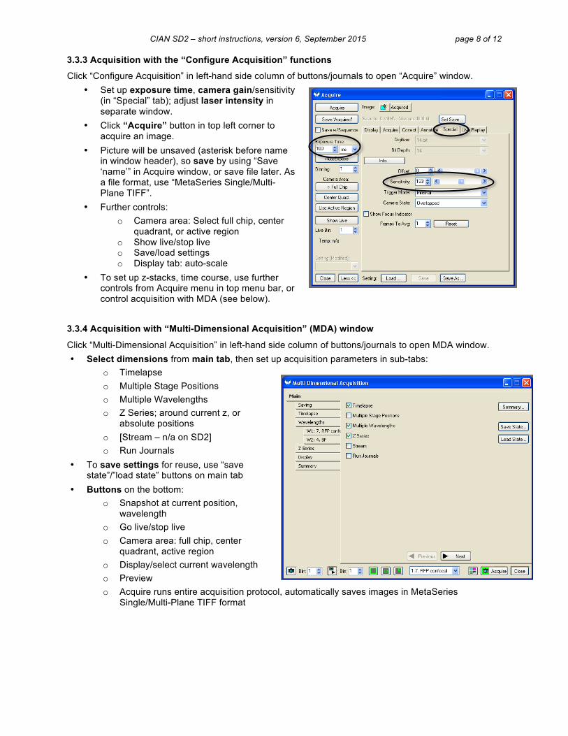
3.3.3 Acquisition with the “Configure Acquisition” functions
Click “Configure Acquisition” in left-hand side column of buttons/journals to open “Acquire” window. • Set up exposure time, camera gain/sensitivity
(in “Special” tab); adjust laser intensity in separate window.
• Click “Acquire” button in top left corner to acquire an image.
• Picture will be unsaved (asterisk before name in window header), so save by using “Save ‘name’” in Acquire window, or save file later. As a file format, use “MetaSeries Single/Multi-Plane TIFF”.
• Further controls: o Camera area: Select full chip, center
quadrant, or active region o Show live/stop live o Save/load settings o Display tab: auto-scale
• To set up z-stacks, time course, use further controls from Acquire menu in top menu bar, or control acquisition with MDA (see below).
3.3.4 Acquisition with “Multi-Dimensional Acquisition” (MDA) window
Click “Multi-Dimensional Acquisition” in left-hand side column of buttons/journals to open MDA window. • Select dimensions from main tab, then set up acquisition parameters in sub-tabs:
o Timelapse o Multiple Stage Positions o Multiple Wavelengths o Z Series; around current z, or
absolute positions o [Stream – n/a on SD2] o Run Journals
• To save settings for reuse, use “save state”/”load state” buttons on main tab
• Buttons on the bottom: o Snapshot at current position,
wavelength o Go live/stop live o Camera area: full chip, center
quadrant, active region o Display/select current wavelength o Preview o Acquire runs entire acquisition protocol, automatically saves images in MetaSeries
Single/Multi-Plane TIFF format

CIAN SD2 – short instructions, version 6, September 2015 page 9 of 12
4 - Shutting down SD2
1. While in the acquisition software, close the confocal fluorescence shutter (Fig 7, second panel)
2. Switch light path to eyepiece (Fig 2-1, or in software) 3. Log out of Volocity/Metamorph by closing window 4. Turn off lasers (Fig 1-2), controller (Fig 1-1), Exfo light source (Fig 1-16) if used 5. Log out of the PC, [optional: turn off the computer using Windows if finished using] 6. Lower objectives, turn turret to 10x objective or empty position 7. Clean objectives by wiping off excess oil (see section 2.2) 8. Remove stage insert, shut down CO2 tank, empty and dry humidifier bottle if used 9. Turn off SD2 - long button on APC UPS (Fig 1-10), push and hold until you hear second beep,
then release 10. Carefully replace the dust cover on the microscope
5 - Saving data on the Server
1. Make sure to exit Volocity or Metamorph before moving any files 2. Connect to the server (start menu, run: \\10.1.0.3), open window for your folder on the server 3. Locate your library on the PC and drag it into your server folder 4. Delete the library from its original location on the hard disk as soon as possible; very large
projects will have to be removed immediately after backing up. No long-term storage will be allowed on the computer.
5. To access your data from outside CIAN, connect to the server “Perola” via its public IP address: 132.206.213.90 You must be on the McGill network, either via a wired connection, or by VPN, to connect to Perola. For access from Windows computers you may need a tool like WinSCP.]
Note: NEVER ACQUIRE DATA DIRECTLY ONTO THE SERVER (i.e. over the network) but acquire on the PC and then move or copy files. NEVER OPEN A VOLOCITY LIBRARY OVER THE NETWORK, but move or copy it off the server to the computer you work on, and then open. The library could otherwise be irretrievably damaged.
CIAN SD2 – short instructions, version 6, September 2015 page 10 of 12
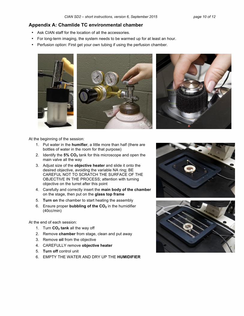
Appendix A: Chamlide TC environmental chamber • Ask CIAN staff for the location of all the accessories. • For long-term imaging, the system needs to be warmed up for at least an hour. • Perfusion option: First get your own tubing if using the perfusion chamber.
At the beginning of the session:
1. Put water in the humifier, a little more than half (there are bottles of water in the room for that purpose)
2. Identify the 5% CO2 tank for this microscope and open the main valve all the way
3. Adjust size of the objective heater and slide it onto the desired objective, avoiding the variable NA ring; BE CAREFUL NOT TO SCRATCH THE SURFACE OF THE OBJECTIVE IN THE PROCESS; attention with turning objective on the turret after this point
4. Carefully and correctly insert the main body of the chamber on the stage, then put on the glass top frame
5. Turn on the chamber to start heating the assembly 6. Ensure proper bubbling of the CO2 in the humidifier
(40cc/min) At the end of each session:
1. Turn CO2 tank all the way off 2. Remove chamber from stage, clean and put away 3. Remove oil from the objective 4. CAREFULLY remove objective heater 5. Turn off control unit 6. EMPTY THE WATER AND DRY UP THE HUMIDIFIER

CIAN SD2 – short instructions, version 6, September 2015 page 11 of 12
Appendix B: Technical data for SD2
Microscope: Quorum WaveFX spinning disk confocal system, on a Leica DMI6000B inverted microscope, fully motorized, with a Hamamatsu EM-CCD camera; Live Cell Instruments Chamlide TC environmental control system; Mosaic Targeted Illumination system (Andor) Objectives:
Position Objective Phase/DIC µm/pixel FD FA 1 10x/0.3 dry PH1 0.9940 9
2 20x/0.7 oil-glyc-water* DIC 0.4987 12
3 20x/0.5 dry PH2 0.4987 12
4 40x/1.25-0.75** oil DIC 0.2532 Completely closed
12
5 63x/1.40-0.6 oil DIC 0.1592 Completely closed
12
6 100x/1.40-0.7 oil DIC 0.1010 Completely closed
12
* can be adjusted for oil, glycerol, or water immersion ** make sure to adjust for highest NA Confocal mode: Lasers, fluorescence emission filters:
Lasers (all diode) Emission filters Typical fluorophore 440nm, 15mW 483/32 CFP
491nm, 25mW 520/35 GFP 543/40 YFP
561nm, 50mW 624/40 RFP/mCherry 638nm, 30mW 692/40 FarRedFP
593/40 OFP/Cy3 645/75* L-Cy5
*Available on demand Wide-field fluorescence: Light source: X-Cite120 metal-halide fluorescence lamp, 120W Fluorescence filter cubes:
Filter set Excitation Dichroic Emission Typical fluorophore
CGFP BP 436/20 455 BP 480/40 CFP GFP BP 470/40 500 BP 525/50 GFP TX2 BP 560/40 595 BP 645/75 Texas Red
CIAN SD2 – short instructions, version 6, September 2015 page 12 of 12
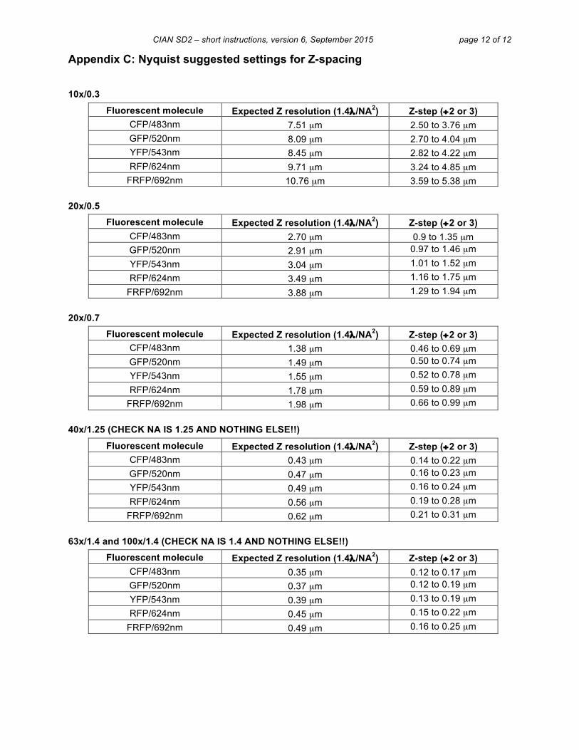
Appendix C: Nyquist suggested settings for Z-spacing
10x/0.3
Fluorescent molecule Expected Z resolution (1.4λ /NA2) Z-step (÷2 or 3) CFP/483nm 7.51 µm 2.50 to 3.76 µm GFP/520nm 8.09 µm 2.70 to 4.04 µm YFP/543nm 8.45 µm 2.82 to 4.22 µm RFP/624nm 9.71 µm 3.24 to 4.85 µm
FRFP/692nm 10.76 µm 3.59 to 5.38 µm 20x/0.5
Fluorescent molecule Expected Z resolution (1.4λ /NA2) Z-step (÷2 or 3) CFP/483nm 2.70 µm 0.9 to 1.35 µm GFP/520nm 2.91 µm 0.97 to 1.46 µm YFP/543nm 3.04 µm 1.01 to 1.52 µm RFP/624nm 3.49 µm 1.16 to 1.75 µm
FRFP/692nm 3.88 µm 1.29 to 1.94 µm 20x/0.7
Fluorescent molecule Expected Z resolution (1.4λ /NA2) Z-step (÷2 or 3) CFP/483nm 1.38 µm 0.46 to 0.69 µm GFP/520nm 1.49 µm 0.50 to 0.74 µm YFP/543nm 1.55 µm 0.52 to 0.78 µm RFP/624nm 1.78 µm 0.59 to 0.89 µm
FRFP/692nm 1.98 µm 0.66 to 0.99 µm 40x/1.25 (CHECK NA IS 1.25 AND NOTHING ELSE!!)
Fluorescent molecule Expected Z resolution (1.4λ /NA2) Z-step (÷2 or 3) CFP/483nm 0.43 µm 0.14 to 0.22 µm GFP/520nm 0.47 µm 0.16 to 0.23 µm YFP/543nm 0.49 µm 0.16 to 0.24 µm RFP/624nm 0.56 µm 0.19 to 0.28 µm
FRFP/692nm 0.62 µm 0.21 to 0.31 µm 63x/1.4 and 100x/1.4 (CHECK NA IS 1.4 AND NOTHING ELSE!!)
Fluorescent molecule Expected Z resolution (1.4λ /NA2) Z-step (÷2 or 3) CFP/483nm 0.35 µm 0.12 to 0.17 µm GFP/520nm 0.37 µm 0.12 to 0.19 µm YFP/543nm 0.39 µm 0.13 to 0.19 µm RFP/624nm 0.45 µm 0.15 to 0.22 µm
FRFP/692nm 0.49 µm 0.16 to 0.25 µm