Embed Size (px)
Citation preview
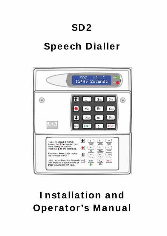
SD2
Speech Dialler
Installation and Operator’s Manual
2
CONTENTS
OVERVIEW ................................................................. 3 MAIN FEATURES.......................................................... 4 SD2 LAYOUT............................................................... 7 INSTALLATION REQUIREMENTS .................................... 8 PCB LAYOUT ............................................................... 8 CONNECTIONS TO THE CONTROL PANEL........................ 9 CONTROL PANEL CONNECTION TABLE ......................... 11 CONNECTIONS TO THE TELEPHONE LINE ..................... 12 COMMISSIONING ...................................................... 13 ACCESSING THE PROGRAMMING MENU ....................... 14 PROGRAMMING MENU OPTIONS.................................. 15 CONTACT DETAILS .................................................... 16 MESSAGES ............................................................... 19 ACCESS CODES......................................................... 26 ACKNOWLEDGEMENT AND ABORT OPTIONS ................. 28 OUTPUT OPTIONS...................................................... 30 CALL ROUTING OPTIONS............................................ 33 SET DATE AND TIME.................................................. 36 VIEW LOG ................................................................ 37 TEST OPTIONS.......................................................... 39 LEAVING PROGRAMMING ........................................... 44 USER GUIDE............................................................. 45 RECORDING AND PLAYING A MEMO LOCALLY ............... 46 USING THE REMOTE ACCESS FEATURE ........................ 48 THE REMOTE ACCESS MENU ....................................... 49 RECORD/PLAY VOICE MESSAGES ................................ 51 TEXT EDITING KEYS .................................................. 52 SPECIFICATIONS....................................................... 53 QUICK REFERENCE .................................................... 54 QUICK REFERENCE .................................................... 55
3
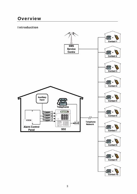
Overview
Introduction
4
Main Features
The SD2 provides a means of communicating alarm information from a control panel to either a standard or a mobile telephone. The unit normally connects to an alarm control panel, which provides the necessary power and battery back up.
Triggers:
The SD2 has four trigger inputs. You can assign a voice message and/or a text message to each input. The unit can also send a message/or a text message when the triggers have been restored. For most applications you may connect the trigger inputs to an alarm control panel's communicator outputs or bell output. You can also connect other devices, such as smoke detectors or temperature sensors, directly to the trigger inputs. The unit allows you to program the polarity of the trigger inputs as either positive or negative applied/removed.
Contacts:
The SD2 will store up to 10 contacts: you can assign each one a name, telephone number, message type, and acknowledgement type. DO NOT use the SD2 to call the Police via the Emergency Services phone numbers.
Voice Messages:
The SD2 has a built-in microphone and speaker to allow you to record and replay audio messages directly from the unit. The SD2 can store up to four separate alarm messages, four restore alarm messages (a different message can be sent when the trigger event has been removed) and one common message (normally used to store the name and address of the premises). Each message can be up to 30 seconds in length. Voice Messages A and Voice Restore Message A are related to trigger input 1; Voice Messages B and Voice Restore Message B are related to trigger input 2 and so on. Make sure that you record voice messages that reflect the type of alarm that is connected to the trigger input. For example, if you connect input 1 to the fire output of an alarm/fire control panel then make sure that Message 1 states that there is a fire alarm at the premises.
5
Text Messages:
The SD2 can also send text messages to mobile telephones using the SMS text service (Short Message Service). The unit does this by calling a SMS service centre, which takes the text message from the SD2 and forwards it to the contact's mobile telephone. The unit can store up to four separate 32-character alarm messages, four 32-character restore alarm messages (a different message can be sent when the trigger event has been removed) and one common message (normally used to store the name and address of the premises). When the unit sends a text message, it adds the alarm message to the site details message. The site details message would normally hold the name or details of the premises being protected.
Acknowledgement:
On receiving a voice message call from the SD2 the contact person answering the call can acknowledge it at any time by pressing 8 on their telephone. If contact does not acknowledge the voice message then the SD2 repeats the message four times, after which the unit abandons the call and dials the next available contact.
Call-Abort:
The SD2 has several call-abort options, which include restoring the trigger input or entering the operator’s passcode. When the unit has aborted a call it immediately shuts down and returns to its normal standby mode.
Outputs:
The SD2 has programmable outputs that you can use to indicate the status of the unit. You may also program the outputs for remote control. For example, you could use this facility to remotely turn outputs on and off with a touch-tone telephone.
Temperature sensor:
The unit can display current ambient temperature. You can program temperature high and low alarms, linking them to two corresponding output types.
Time and date:
The unit contains an internal clock which can display the current time and date. In addition, the time and date will be added to text messages and trigger events thus providing a useful audit trial in the log. Please note that the time and date feature is designed as a guide.
6
Listen-In Mode:
The SD2 has a listen-in mode, which switches an internal microphone to the telephone line so that you can hear activity at the protected site. The contact can activate the listen-in mode at the time of receiving a voice message or by calling into the SD2 and using the Remote Access feature.
Talkback Mode:
The SD2 has a talkback mode, which switches the internal loudspeaker to the telephone line so that you can talk to the protected site. The contact can activate the talkback mode at the time of receiving a voice message or by calling into the SD2 and using the Remote Access feature.
Message:
The SD2 has a message feature, which allows you to record up to 15 seconds of audio. A user can record a message locally, at the unit, or remotely, using a touch-tone telephone. After recording a new message the unit will indicate it on the display and optionally gives a beep. You can also program the message feature to record when a trigger input is activated.
Remote Access:
If you enable this feature you can access the SD2 remotely by dialling into the unit with a touch-tone telephone. Once connected you can turn on and off the two outputs, activate the listen-in/talkback mode, listen to the message, or record a new message.
7
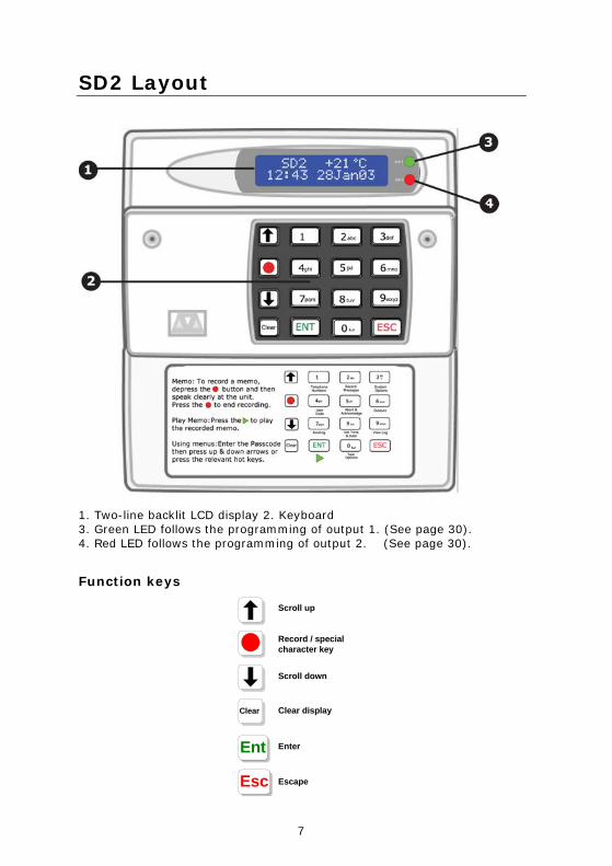
SD2 Layout
1. Two-line backlit LCD display 2. Keyboard 3. Green LED follows the programming of output 1. (See page 30). 4. Red LED follows the programming of output 2. (See page 30).
Function keys
Ent
Esc
ClearClear
Scroll up
Record / specialcharacter key
Scroll down
Clear display
Enter
Escape
8
Installation Requirements
General
The SD2 is designed to connect to an intruder alarm control panel or similar. The control panel must have an auxiliary power output of between 10.5V and 14V, and the ability to provide a minimum of 100mA. The unit is supplied with a 2-metre telephone lead, which plugs directly into any standard BT socket. Cooper Security recommends that you site the unit as near to a BT telephone socket as possible. If this it not possible you should either obtain an approved BT extension lead or permanently wire the unit to the BT socket (see Connections to the Telephone Line).
Mounting Instructions
Separate the cover from the base by using a screwdriver to push two of the retaining clips (top or bottom) inwards from the base indents. Remove cover assembly and store in a safe place. Hold the base in position (keyhole to the top) and mark the three securing holes. Remove the base then drill and plug the holes. Pass all cables into the base through the cable entries and then secure the base to wall.
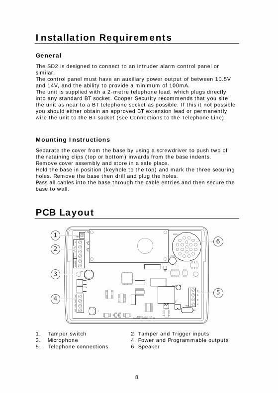
PCB Layout
1. Tamper switch 2. Tamper and Trigger inputs 3. Microphone 4. Power and Programmable outputs 5. Telephone connections 6. Speaker
9
Connection terminals on the SD2 are described as either “Safety Extra Low Voltage” circuits (SELV) or “Telecommunications Network Voltage” circuits (TNV). It is important that the TNV connections are only connected to the PSTN, and SELV circuits are only connected to designated SELV circuits. Interconnection circuits should be such that the equipment continues to comply with the requirements of 4.2 of EN 41003 for TNV circuits and 2.3 of EN 60950 for SELV circuits, after making connections between circuits.
Connections to the control panel
Before making any connection to the SD2 isolate ALL power from the control panel (AC mains and battery). Do not continue if there is power still present on the control panel.
+12V & 0V
Connect these terminals to the 12V auxiliary power supply of the alarm control panel.
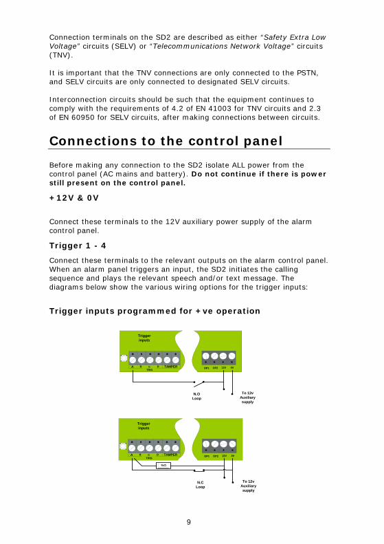
Trigger 1 - 4
Connect these terminals to the relevant outputs on the alarm control panel. When an alarm panel triggers an input, the SD2 initiates the calling sequence and plays the relevant speech and/or text message. The diagrams below show the various wiring options for the trigger inputs:
Trigger inputs programmed for +ve operation
TAMPERTRIG
A B C DOP1 OP2 12V 0V
Triggerinputs
To 12vAuxiliarysupply
N.OLoop
TAMPERTRIG
A B C DOP1 OP2 12V 0V
Triggerinputs
To 12vAuxiliarysupply
N.CLoop
10
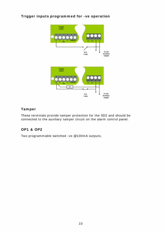
Trigger inputs programmed for -ve operation
TAMPERTRIG
A B C DOP1 OP2 12V 0V
Triggerinputs
To 12vAuxiliarysupply
N.O.Loop
TAMPERTRIG
A B C DOP1 OP2 12V 0V
Triggerinputs
To 12vAuxiliarysupply
N.CLoop
Tamper
These terminals provide tamper protection for the SD2 and should be connected to the auxiliary tamper circuit on the alarm control panel.
OP1 & OP2
Two programmable switched -ve @100mA outputs.
11
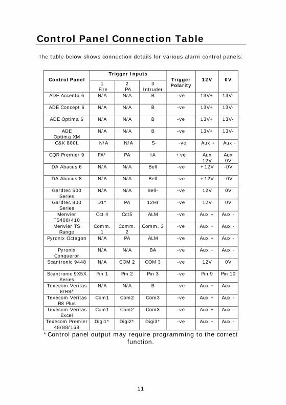
Control Panel Connection Table
The table below shows connection details for various alarm control panels:
Trigger Inputs Control Panel
1 Fire
2 PA
3 Intruder
Trigger Polarity
12V
0V
ADE Accenta 6 N/A N/A B -ve 13V+ 13V-
ADE Concept 6 N/A N/A B -ve 13V+ 13V-
ADE Optima 6 N/A N/A B -ve 13V+ 13V-
ADE Optima XM
N/A N/A B -ve 13V+ 13V-
C&K 800L N/A N/A S- -ve Aux + Aux -
CQR Premier 9 FA* PA IA +ve Aux 12V
Aux 0V
DA Abacus 6 N/A N/A Bell -ve +12V -0V
DA Abacus 8 N/A N/A Bell -ve +12V -0V
Gardtec 500 Series
N/A N/A Bell- -ve 12V 0V
Gardtec 800 Series
D1* PA 12Hr -ve 12V 0V
Menvier TS400/410
Cct 4 Cct5 ALM -ve Aux + Aux -
Menvier TS Range
Comm. 1
Comm. 2
Comm. 3 -ve Aux + Aux -
Pyronix Octagon N/A PA ALM -ve Aux + Aux -
Pyronix Conqueror
N/A N/A BA -ve Aux + Aux -
Scantronic 9448 N/A COM 2 COM 3 -ve 12V 0V
Scantronic 9X5X Series
Pin 1 Pin 2 Pin 3 -ve Pin 9 Pin 10
Texecom Veritas 8/R8/
N/A N/A B -ve Aux + Aux -
Texecom Veritas R8 Plus
Com1 Com2 Com3 -ve Aux + Aux -
Texecom Veritas Excel
Com1 Com2 Com3 -ve Aux + Aux -
Texecom Premier 48/88/168
Digi1* Digi2* Digi3* -ve Aux + Aux -
*Control panel output may require programming to the correct function.
12
Connections to the Telephone Line
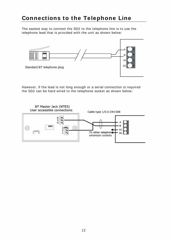
The easiest way to connect the SD2 to the telephone line is to use the telephone lead that is provided with the unit as shown below:
A
B
A1
A2Standard BT telephone plug
However, if the lead is not long enough or a serial connection is required the SD2 can be hard wired to the telephone socket as shown below:
13
Commissioning
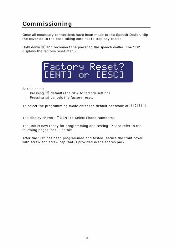
Once all necessary connections have been made to the Speech Dialler, clip the cover on to the base taking care not to trap any cables. Hold down 9 and reconnect the power to the speech dialler. The SD2 displays the factory-reset menu:
At this point: Pressing [ defaults the SD2 to factory settings. Pressing ] cancels the factory reset.
To select the programming mode enter the default passcode of 1234.
The display shows “ ¬¦ENT to Select Phone Numbers”. The unit is now ready for programming and testing. Please refer to the following pages for full details. After the SD2 has been programmed and tested, secure the front cover with screw and screw cap that is provided in the spares pack.
14
Accessing the Programming Menu
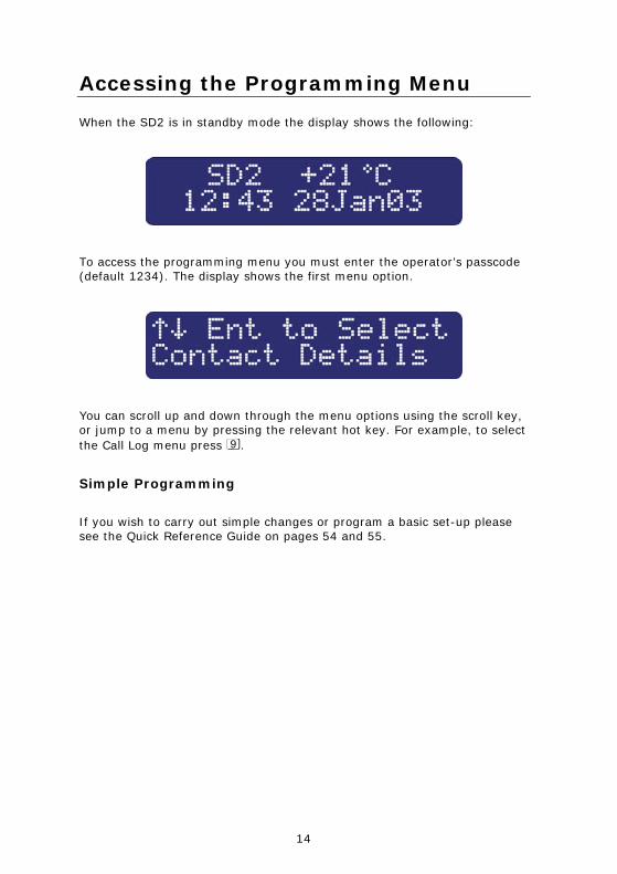
When the SD2 is in standby mode the display shows the following:
To access the programming menu you must enter the operator’s passcode (default 1234). The display shows the first menu option.
You can scroll up and down through the menu options using the scroll key, or jump to a menu by pressing the relevant hot key. For example, to select the Call Log menu press 9.
Simple Programming
If you wish to carry out simple changes or program a basic set-up please see the Quick Reference Guide on pages 54 and 55.
15
Programming Menu Options
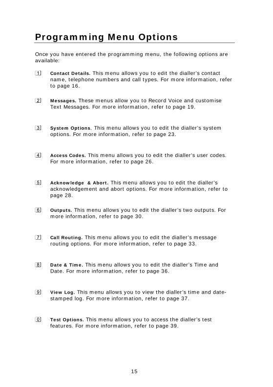
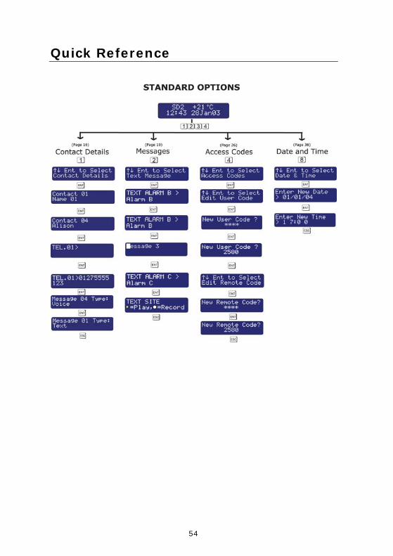
Once you have entered the programming menu, the following options are available: 1 Contact Details. This menu allows you to edit the dialler’s contact
name, telephone numbers and call types. For more information, refer to page 16.
2 Messages. These menus allow you to Record Voice and customise Text Messages. For more information, refer to page 19.
3 System Options. This menu allows you to edit the dialler’s system options. For more information, refer to page 23.
4 Access Codes. This menu allows you to edit the dialler’s user codes. For more information, refer to page 26.
5 Acknowledge & Abort. This menu allows you to edit the dialler’s acknowledgement and abort options. For more information, refer to page 28.
6 Outputs. This menu allows you to edit the dialler’s two outputs. For more information, refer to page 30.
7 Call Routing. This menu allows you to edit the dialler’s message routing options. For more information, refer to page 33.
8 Date & Time. This menu allows you to edit the dialler’s Time and Date. For more information, refer to page 36.
9 View Log. This menu allows you to view the dialler’s time and date-stamped log. For more information, refer to page 37.
0 Test Options. This menu allows you to access the dialler’s test features. For more information, refer to page 39.
16
Contact Details
The SD2 can store up to 10 contacts; each contact is assigned the following parameters:
Name
Up to 16 characters can be assigned to the contact name.
Telephone No.
Each contact’s telephone number can have up to 24 digits. When programming the contact’s telephone number the key can be used to insert the following command characters: * Star: Inserts a * into the telephone number. # Hash: Inserts a # in the telephone number.
, Pause: If the unit is connected to an internal telephone system you normally have to dial a number to get an external line, wait a couple of seconds, then dial the actual number. The pause command can be used to insert a 3 second delay, e.g., (9,) 0161 123456.
Contact Type
The contact type can be programmed to one of the following options:
Voice Only:
The SD2 dials the contact telephone number and plays the common phrase plus the relevant voice message, repeated four times.
Text Only:
The SD2 dials the SMS service centre and relays the relevant text message to the Contact’s telephone number.
17
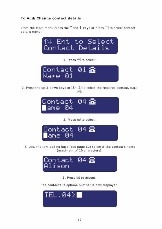
To Add/Change contact details
From the main menu press the ¬and ¦ keys or press 1 to select contact details menu:
1. Press [ to select:
2. Press the up & down keys or 1~8 to select the required contact, e.g.: 4:
3. Press [ to select:
4. Use, the text editing keys (see page 52) to enter the contact’s name (maximum of 10 characters).
5. Press [ to accept:
The contact’s telephone number is now displayed.
18
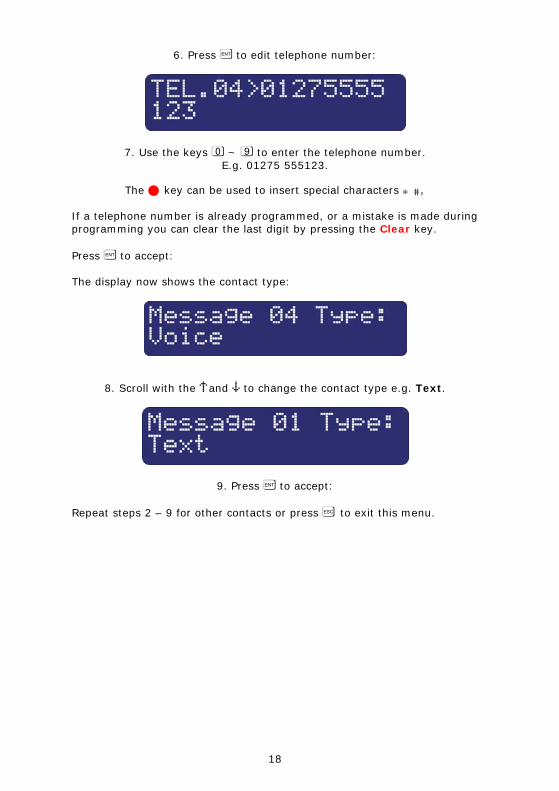
6. Press [ to edit telephone number:
7. Use the keys 0 ~ 9 to enter the telephone number. E.g. 01275 555123.
The key can be used to insert special characters * #,
If a telephone number is already programmed, or a mistake is made during programming you can clear the last digit by pressing the Clear key. Press [ to accept: The display now shows the contact type:
8. Scroll with the ¬and ¦ to change the contact type e.g. Text.
9. Press [ to accept:
Repeat steps 2 – 9 for other contacts or press ] to exit this menu.
19
Messages
Recording Messages
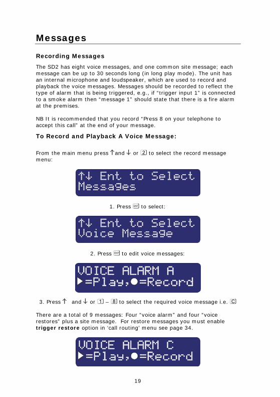
The SD2 has eight voice messages, and one common site message; each message can be up to 30 seconds long (in long play mode). The unit has an internal microphone and loudspeaker, which are used to record and playback the voice messages. Messages should be recorded to reflect the type of alarm that is being triggered, e.g., if “trigger input 1” is connected to a smoke alarm then “message 1” should state that there is a fire alarm at the premises. NB It is recommended that you record “Press 8 on your telephone to accept this call” at the end of your message.
To Record and Playback A Voice Message:
From the main menu press ¬and ¦ or 2 to select the record message menu:
1. Press [ to select:
2. Press [ to edit voice messages:
3. Press ¬ and ¦ or 1 – 8 to select the required voice message i.e. C There are a total of 9 messages: Four “voice alarm” and four “voice restores” plus a site message. For restore messages you must enable trigger restore option in ‘call routing’ menu see page 34.
20
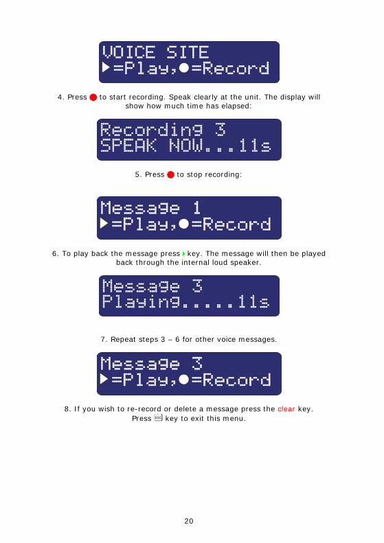
4. Press to start recording. Speak clearly at the unit. The display will show how much time has elapsed:
5. Press to stop recording:
6. To play back the message press key. The message will then be played back through the internal loud speaker.
7. Repeat steps 3 – 6 for other voice messages.
8. If you wish to re-record or delete a message press the clear key. Press ] key to exit this menu.
21
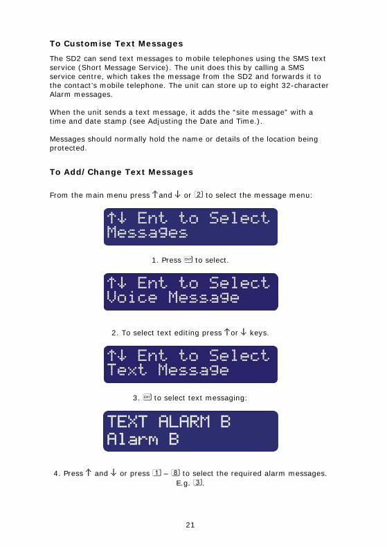
To Customise Text Messages
The SD2 can send text messages to mobile telephones using the SMS text service (Short Message Service). The unit does this by calling a SMS service centre, which takes the message from the SD2 and forwards it to the contact’s mobile telephone. The unit can store up to eight 32-character Alarm messages. When the unit sends a text message, it adds the “site message” with a time and date stamp (see Adjusting the Date and Time.). Messages should normally hold the name or details of the location being protected.
To Add/Change Text Messages
From the main menu press ¬and ¦ or 2 to select the message menu:
1. Press [ to select.
2. To select text editing press ¬or ¦ keys.
3. [ to select text messaging:
4. Press ¬ and ¦ or press 1 – 8 to select the required alarm messages. E.g. 3.
22
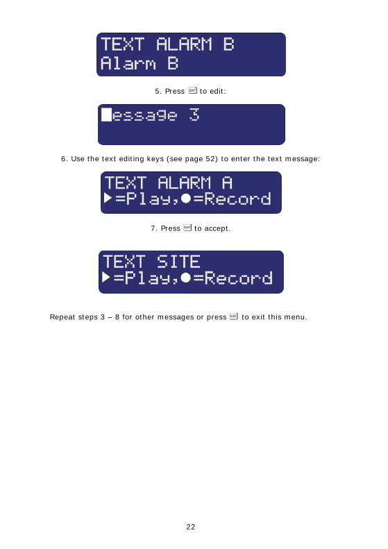
5. Press [ to edit:
6. Use the text editing keys (see page 52) to enter the text message:
7. Press [ to accept.
Repeat steps 3 – 8 for other messages or press ] to exit this menu.
23
System Options
Editing the System Options Menu
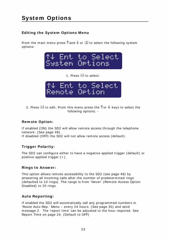
From the main menu press ¬and ¦ or 3 to select the following system options:
1. Press [ to select:
2. Press [ to edit. From this menu press the ¬or ¦ keys to select the following options: -
Remote Option:
If enabled (ON) the SD2 will allow remote access through the telephone network. (See page 48). If disabled (OFF) the SD2 will not allow remote access (default).
Trigger Polarity:
The SD2 can configure either to have a negative applied trigger (default) or positive applied trigger (+).
Rings to Answer:
This option allows remote accessibility to the SD2 (see page 48) by answering all incoming calls after the number of predetermined rings (defaulted to 10 rings). The range is from ‘Never’ (Remote Access Option Disabled) to 20 rings.
Auto Reporting:
If enabled the SD2 will automatically call any programmed numbers in ‘Route Auto Rep.’ Menu – every 24 hours. (See page 35) and send message 2. The ‘report time’ can be adjusted to the hour required. See Report Time on page 24. (Default to OFF)
24
Note: this message will not require an acknowledgement.
Report Time:
This option sets the time that the Auto Reporting Message is transmitted (Default 12:00 hours).
Scroll with ¬and ¦ keys to select the required hour.
SMS Call Number:
This option allows the editing of the default SMS service centre used by SD2 to send a text message. The SD2 defaults to the O2 SMS centre. Listed below are other service centres that can be used: Service Provider Telephone No. Protocol O2 - UK +44 (0) 7860 980480 8,N, 1 One2One- UK +44 (0) 7958 879889 7,E, 1 Vodafone Mobiles - UK +44 (0) 7785 499993 8,N, 1
If your SD2 is connected to a private telephone system, remember that you may have to include an extra digit (for example ‘9’) to gain access to the public telephone network. If you are calling a SMS service centre in a different country you need to make sure that the contact’s mobile telephone number has the international country code, e.g., if the contact’s UK mobile number is 07801 123 456 it needs to be entered as 447801 123 456.
SMS Format:
The SD2 can be configured to communicate with the SMS service centre either using 7 data bits, even parity and 1 stop bit. Or, using 8 data bits, no parity, and 1 stop. See SMS Call Number for further details. When going via a switchboard system, remember to insert the number used to get an external line. The protocol used by each service centre may vary from one provider to another. Please make sure that the SD2 protocol is configured correctly; see SMS Parity option.
One Ring Answer:
If enabled (ON) the SD2 will use the answer defeat feature, which operates as follows: To obtain remote access the caller must dial the unit and wait for the line to ring several times (but not more than the number of rings programmed for the Ring Count, see next option). The caller must then hang up the call and redial the unit within 60 seconds. The SD2 will then
25
answer the incoming call and allow the caller to use the ‘remote access feature’, see page 48. If disabled (OFF) the SD2 will answer all incoming calls after the number of rings programmed for the Ring Count, see option below.
Flash On Message:
If enabled (ON) the SD2 will flash the display backlight on and off when message is waiting (default). Listening to the message cancels the display flashing. If disabled (OFF) the SD2 will not flash the display backlight.
Beep On Message:
If enabled (ON) the SD2 will beep every minute when message is waiting. Listening to the message cancels the beep. If disabled (OFF) the SD2 will not beep (default).
Auto Record:
If enabled (ON) the SD2 will automatically switch the microphone on and start recording for up to 30 seconds when any trigger input is present. The recording is then stored in the ‘Memo feature‘. Playing back the recording can then be either accessed using the remote access feature (see page 49) or via the memo playback feature via the keypad (see page 46). If disabled (OFF) the SD2 will not automatically record a message (default).
Temperature High:
This option allows you to set the temperature at which the temperature high output will activate (see “Output Options” on page 30 ). Working range of 0°C to 50°C (default 40°C).
Temperature Low:
This option allows you to set the temperature at which the temperature low output will activate (see “Output Options” on page 30). Working range of 0°C to 50°C (default 5°C).
Temp Display:
If enabled (ON) the SD2’s display will show the current ambient temperature in degrees centigrade, (default). If disabled (OFF) the SD2’s display will not show the ambient temperature.
26
Long play:
If enabled (ON) the recordable messages have a maximum record time of 30 seconds. If disabled (OFF) the recordable messages have a maximum record time of 15 seconds; also the speech is of a higher quality, (default).
Line Fault:
If enabled (ON) the SD2 logs any line fault and displays ‘line fault’ on the display; it also produces an audible tone every 60 seconds. Entering programming mode will silence the audible tone if the line fault persists. If Disabled (OFF) the SD2 logs any line fault, (default).
Access Codes
The SD2 is protected by a 4-digit passcode; the passcode is required to gain access to the programming menus. The operator’s passcode is also used for aborting calls. The default operator’s access code is “1234”.
To change the operator’s passcode:
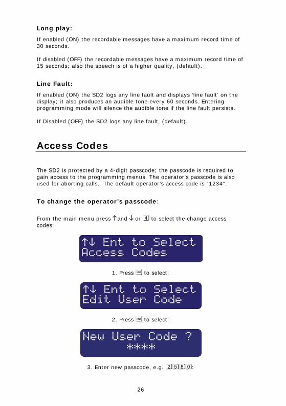
From the main menu press ¬and ¦ or 4 to select the change access codes:
1. Press [ to select:
2. Press [ to select:
3. Enter new passcode, e.g. 2580:
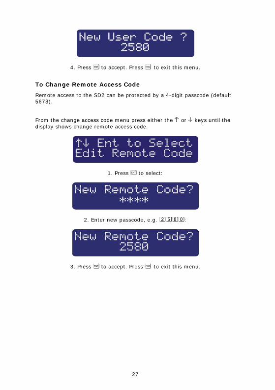
27
4. Press [ to accept. Press ] to exit this menu.
To Change Remote Access Code
Remote access to the SD2 can be protected by a 4-digit passcode (default 5678).
From the change access code menu press either the ¬ or ¦ keys until the display shows change remote access code.
1. Press [ to select:
2. Enter new passcode, e.g. 2580:
3. Press [ to accept. Press ] to exit this menu.
28
Acknowledgement and Abort Options
Abort options
Occasionally, you may trigger your alarm by accident and cause the SD2 to send an unwanted call. When this happens the unit can be aborted. When a call is aborted the SD2 immediately hangs-up and returns to its normal standby mode. The trigger inputs can be programmed to one of the following options:
None
Trigger inputs cannot be aborted, (default).
Passcode Only
The selected trigger input can only be aborted by entering the operator’s passcode into the SD2.
Code or Restore
The selected trigger input can be aborted by either entering the operator’s passcode into the SD2 or by restoring the trigger input to its normal healthy condition.
Restore Only
The selected trigger input can only be aborted by restoring the trigger input to its normal healthy condition.
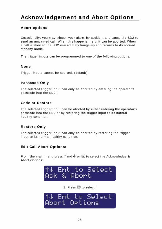
Edit Call Abort Options:
From the main menu press ¬and ¦ or 5 to select the Acknowledge & Abort Options:
1. Press [ to select:
29
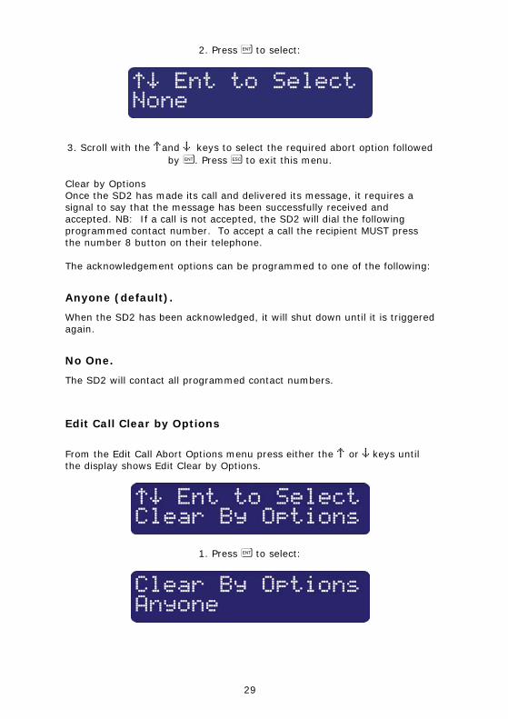
2. Press [ to select:
3. Scroll with the ¬and ¦ keys to select the required abort option followed by [. Press ] to exit this menu.
Clear by Options Once the SD2 has made its call and delivered its message, it requires a signal to say that the message has been successfully received and accepted. NB: If a call is not accepted, the SD2 will dial the following programmed contact number. To accept a call the recipient MUST press the number 8 button on their telephone. The acknowledgement options can be programmed to one of the following:
Anyone (default).
When the SD2 has been acknowledged, it will shut down until it is triggered again.
No One.
The SD2 will contact all programmed contact numbers.
Edit Call Clear by Options
From the Edit Call Abort Options menu press either the ¬ or ¦ keys until the display shows Edit Clear by Options.
1. Press [ to select:
30
2. Scroll with the ¬ and ¦ keys to select the required Clear By option followed by [. Press] to exit this menu.
Output Options
The SD2 has two programmable outputs that can be accessed remotely and used for a wide variety of functions. Each output can be programmed to one of the following functions, e.g. switching on lighting or heating/ventilation systems.
OFF:
The output remains off at all times.
Memo Waiting:
This output type activates when the SD2 has a Message waiting and de-activates once the Message has been played.
Remote Access:
This output activates when the SD2 is being accessed remotely with a touch-tone telephone. The output de-activates when call has finished.
Temperature High:
This output activates when the Temperature High setting has been reached. The output de-activates once the temperature falls below the preset temperature (see page 25). Temperature Low: This output activates when the Temperature Low setting has been reached. The output de-activates once the temperature rises above the preset temperature (see page 25).
Listen Active:
This output type activates when the SD2 is using the Listen In feature (see page 50).
Speech Active:
This output type activates when the SD2 is using the Talk Back feature (see page 50).
31
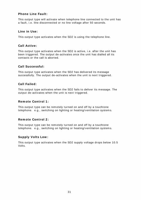
Phone Line Fault:
This output type will activate when telephone line connected to the unit has a fault, i.e. line disconnected or no line voltage after 50 seconds.
Line in Use:
This output type activates when the SD2 is using the telephone line.
Call Active:
This output type activates when the SD2 is active, i.e. after the unit has been triggered. The output de-activates once the unit has dialled all its contacts or the call is aborted.
Call Successful:
This output type activates when the SD2 has delivered its message successfully. The output de-activates when the unit is next triggered.
Call Failed:
This output type activates when the SD2 fails to deliver its message. The output de-activates when the unit is next triggered.
Remote Control 1:
This output type can be remotely turned on and off by a touchtone telephone. e.g., switching on lighting or heating/ventilation systems.
Remote Control 2:
This output type can be remotely turned on and off by a touchtone telephone. e.g., switching on lighting or heating/ventilation systems.
Supply Volts Low:
This output type activates when the SD2 supply voltage drops below 10.5 Volts.
32
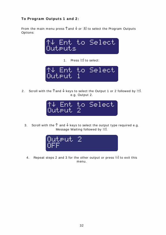
To Program Outputs 1 and 2:
From the main menu press ¬and ¦ or 6 to select the Program Outputs Options:
1. Press [ to select:
2. Scroll with the ¬and ¦ keys to select the Output 1 or 2 followed by [. e.g. Output 2.
3. Scroll with the ¬ and ¦ keys to select the output type required e.g. Message Waiting followed by [.
4. Repeat steps 2 and 3 for the other output or press ] to exit this menu.
33
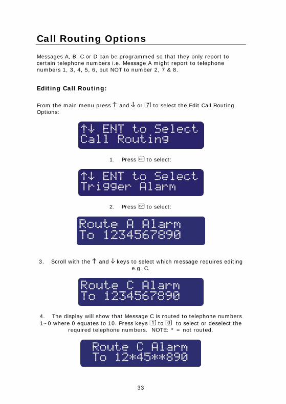
Call Routing Options
Messages A, B, C or D can be programmed so that they only report to certain telephone numbers i.e. Message A might report to telephone numbers 1, 3, 4, 5, 6, but NOT to number 2, 7 & 8.
Editing Call Routing:
From the main menu press ¬ and ¦ or 7 to select the Edit Call Routing Options:
1. Press [ to select:
2. Press [ to select:
3. Scroll with the ¬ and ¦ keys to select which message requires editing e.g. C.
4. The display will show that Message C is routed to telephone numbers 1~0 where 0 equates to 10. Press keys 1 to 0 to select or deselect the
required telephone numbers. NOTE: * = not routed.
34
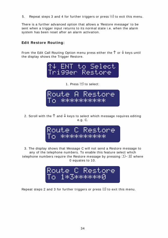
5. Repeat steps 3 and 4 for further triggers or press ] to exit this menu.
There is a further advanced option that allows a ‘Restore message’ to be sent when a trigger input returns to its normal state i.e. when the alarm system has been reset after an alarm activation.
Edit Restore Routing:
From the Edit Call Routing Option menu press either the ¬ or ¦ keys until the display shows the Trigger Restore.
1. Press [ to select:
2. Scroll with the ¬ and ¦ keys to select which message requires editing e.g. C.
3. The display shows that Message C will not send a Restore message to any of the telephone numbers. To enable this feature select which
telephone numbers require the Restore message by pressing 1~0 where 0 equates to 10.
Repeat steps 2 and 3 for further triggers or press ] to exit this menu.
35
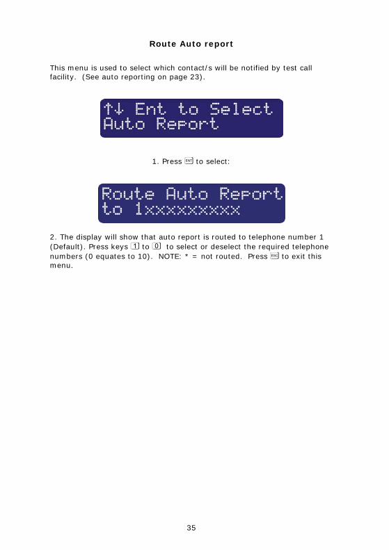
Route Auto report
This menu is used to select which contact/s will be notified by test call facility. (See auto reporting on page 23).
1. Press [ to select:
2. The display will show that auto report is routed to telephone number 1 (Default). Press keys 1 to 0 to select or deselect the required telephone numbers (0 equates to 10). NOTE: * = not routed. Press ] to exit this menu.
36
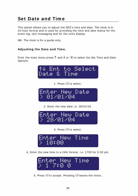
Set Date and Time
This option allows you to adjust the SD2’s time and date. The clock is in 24-hour format and is used for providing the time and date stamp for the event log, text messaging and for the units display. NB: The clock is for a guide only.
Adjusting the Date and Time.
From the main menu press ¬ and ¦ or 8 to select the Set Time and Date Options:
1. Press [ to select:
2. Enter the new date i.e. 28/01/04.
3. Press [ to select:
4. Enter the new time in a 24hr format, i.e. 1700 for 5:00 pm.
5. Press [ to accept. Pressing ] leaves the menu.
37
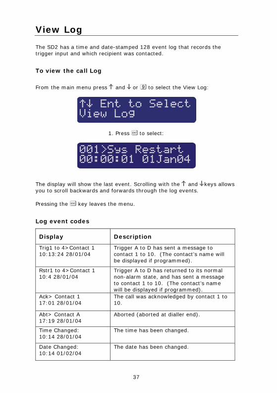
View Log
The SD2 has a time and date-stamped 128 event log that records the trigger input and which recipient was contacted.
To view the call Log
From the main menu press ¬ and ¦ or 9 to select the View Log:
1. Press [ to select:
The display will show the last event. Scrolling with the ¬ and ¦keys allows you to scroll backwards and forwards through the log events. Pressing the ] key leaves the menu.
Log event codes
Display Description
Trig1 to 4>Contact 1 10:13:24 28/01/04
Trigger A to D has sent a message to contact 1 to 10. (The contact’s name will be displayed if programmed).
Rstr1 to 4>Contact 1 10:4 28/01/04
Trigger A to D has returned to its normal non-alarm state, and has sent a message to contact 1 to 10. (The contact’s name will be displayed if programmed).
Ack> Contact 1 17:01 28/01/04
The call was acknowledged by contact 1 to 10.
Abt> Contact A 17:19 28/01/04
Aborted (aborted at dialler end).
Time Changed: 10:14 28/01/04
The time has been changed.
Date Changed: 10:14 01/02/04
The date has been changed.
38
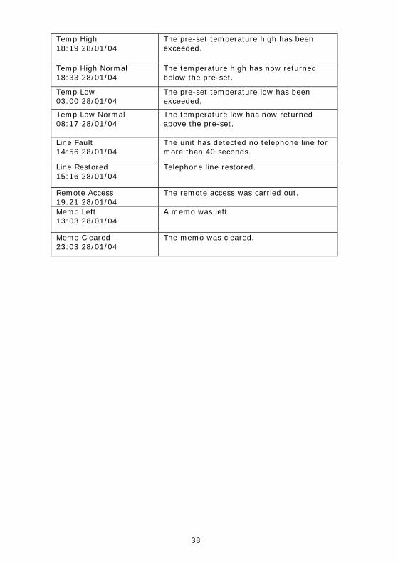
Temp High 18:19 28/01/04
The pre-set temperature high has been exceeded.
Temp High Normal 18:33 28/01/04
The temperature high has now returned below the pre-set.
Temp Low 03:00 28/01/04
The pre-set temperature low has been exceeded.
Temp Low Normal 08:17 28/01/04
The temperature low has now returned above the pre-set.
Line Fault 14:56 28/01/04
The unit has detected no telephone line for more than 40 seconds.
Line Restored 15:16 28/01/04
Telephone line restored.
Remote Access 19:21 28/01/04
The remote access was carried out.
Memo Left 13:03 28/01/04
A memo was left.
Memo Cleared 23:03 28/01/04
The memo was cleared.
39
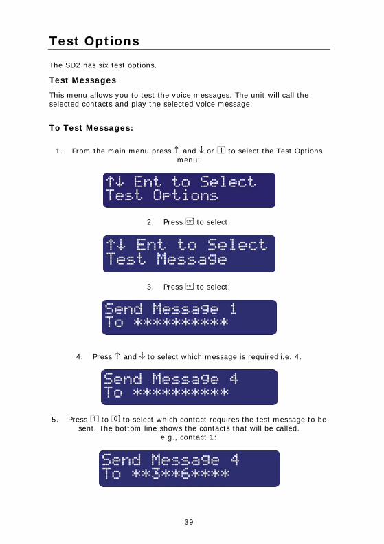
Test Options
The SD2 has six test options.
Test Messages
This menu allows you to test the voice messages. The unit will call the selected contacts and play the selected voice message.
To Test Messages:
1. From the main menu press ¬ and ¦ or 1 to select the Test Options menu:
2. Press [ to select:
3. Press [ to select:
4. Press ¬ and ¦ to select which message is required i.e. 4.
5. Press 1 to 0 to select which contact requires the test message to be sent. The bottom line shows the contacts that will be called.
e.g., contact 1:
40
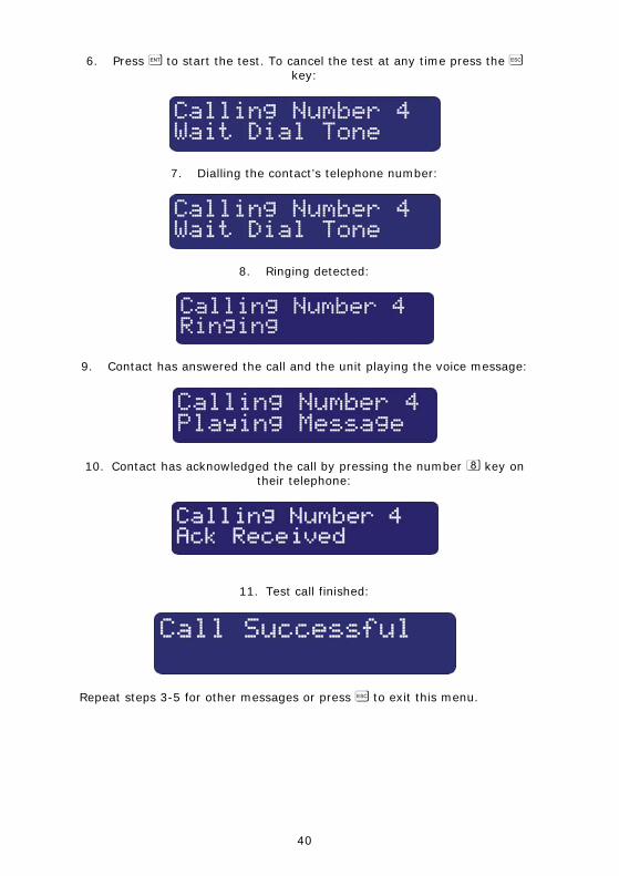
6. Press [ to start the test. To cancel the test at any time press the ] key:
7. Dialling the contact’s telephone number:
8. Ringing detected:
9. Contact has answered the call and the unit playing the voice message:
10. Contact has acknowledged the call by pressing the number 8 key on their telephone:
11. Test call finished:
Repeat steps 3-5 for other messages or press ] to exit this menu.
41
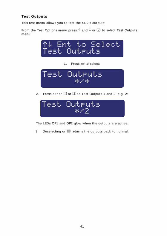
Test Outputs
This test menu allows you to test the SD2’s outputs:
From the Test Options menu press ¬ and ¦ or 2 to select Test Outputs menu:
1. Press [ to select:
2. Press either 1 or 2 to Test Outputs 1 and 2, e.g. 2:
The LEDs OP1 and OP2 glow when the outputs are active.
3. Deselecting or ] returns the outputs back to normal.
42
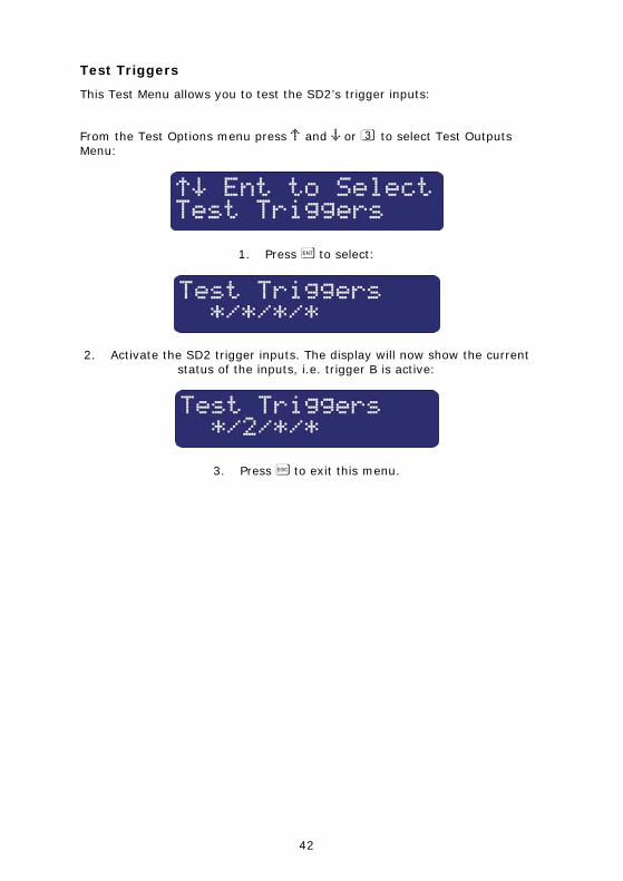
Test Triggers
This Test Menu allows you to test the SD2’s trigger inputs:
From the Test Options menu press ¬ and ¦ or 3 to select Test Outputs Menu:
1. Press [ to select:
2. Activate the SD2 trigger inputs. The display will now show the current status of the inputs, i.e. trigger B is active:
3. Press ] to exit this menu.
43
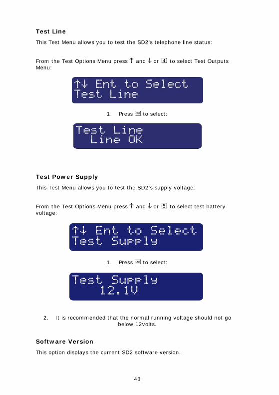
Test Line
This Test Menu allows you to test the SD2’s telephone line status:
From the Test Options Menu press ¬ and ¦ or 4 to select Test Outputs Menu:
1. Press [ to select:
Test Power Supply
This Test Menu allows you to test the SD2’s supply voltage:
From the Test Options Menu press ¬ and ¦ or 5 to select test battery voltage:
¬¦ Ent to SelectTest Supply
1. Press [ to select:
Test Supply12.1V
2. It is recommended that the normal running voltage should not go below 12volts.
Software Version
This option displays the current SD2 software version.
44
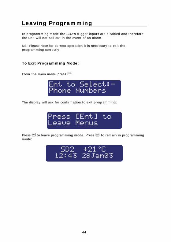
Leaving Programming
In programming mode the SD2’s trigger inputs are disabled and therefore the unit will not call out in the event of an alarm. NB: Please note for correct operation it is necessary to exit the programming correctly.
To Exit Programming Mode:
From the main menu press ]:
The display will ask for confirmation to exit programming:
Press [ to leave programming mode. Press ] to remain in programming mode:
45
User Guide
Voice Message Calls
The SD2 requires a call acknowledgement in order to confirm that the recipient has accepted the call. All contacts must be informed that to accept a call they must press number 8 on their telephone. If a call is not acknowledged by pressing 8, the SD2 will proceed to contact the next programmed number.
How to Acknowledge a Voice Message:
When the telephone rings, answer the call as normal. Listen to the voice message. The message is repeated 3 times in total. When you have understood the message, acknowledge it at any time by pressing the number 8 key on your telephone. You will hear an acknowledgement tone from the SD2 and then the unit will hang up. Now take the necessary action in response to the alarm.
Aborting the Call
If the SD2 is accidentally triggered or you want to stop the calling sequence then one of the following methods can be used:
Entering the Operator’s Passcode
To abort the call sequence, enter your passcode. The display will show ‘Call Aborted’.
Restoring the Trigger Input
To abort the call sequence, restore the trigger input back to its normal condition. Normally this is a simple matter of resetting the alarm control panel. The abort methods that can be used depend on how each trigger input is configured, see page 23.
46
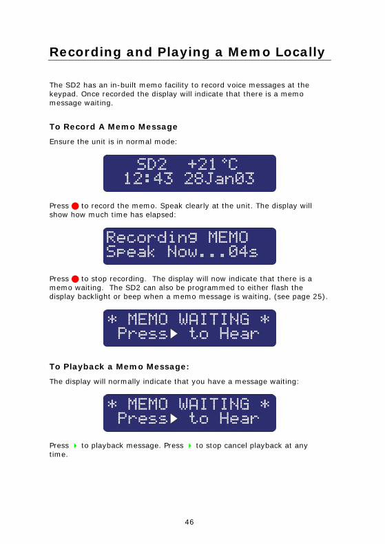
Recording and Playing a Memo Locally
The SD2 has an in-built memo facility to record voice messages at the keypad. Once recorded the display will indicate that there is a memo message waiting.
To Record A Memo Message
Ensure the unit is in normal mode:
Press to record the memo. Speak clearly at the unit. The display will show how much time has elapsed:
Press to stop recording. The display will now indicate that there is a memo waiting. The SD2 can also be programmed to either flash the display backlight or beep when a memo message is waiting, (see page 25).
To Playback a Memo Message:
The display will normally indicate that you have a message waiting:
Press to playback message. Press to stop cancel playback at any time.
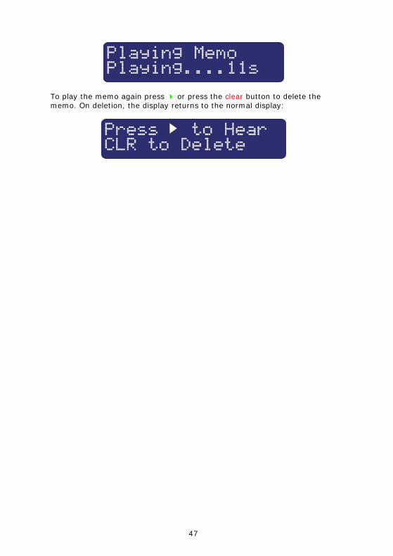
47
To play the memo again press or press the clear button to delete the memo. On deletion, the display returns to the normal display:
48
Using the Remote Access Feature
The Remote Access feature can be used to record messages remotely, listen into the property after an alarm message, and to toggle outputs to turn on lighting etc. This facility is accessed by one of the following methods:
Dial in for Remote Access
This method requires you to call into the SD2 in order to select the Remote Access Menu. If the “Remote Option” is enabled (see page 23) you will need to enter the Remote Access Code (see page 27). The unit is designed to work on dedicated phone lines or shared lines by utilising the Answer Phone Defeat feature (see below). To Dial in for Remote Access (1 ring Answer OFF): Dial the SD2 using a touch-tone telephone. The SD2 will answer your call after the programmed number of rings (see page 23). You will hear a series of high-pitched beeps; at this point enter the ‘Remote Access Code’ on your telephone; you will hear an acceptance tone. The Remote Access menu is now selected.
To Dial in for Remote Access (Answer Phone Defeat ON):
(Note: To enable this feature see “One Ring Answer” on page 24.) Dial the SD2 using a touch-tone telephone. Allow the telephone line to ring two or three times then hang up the call. Wait approximately 10 seconds then redial the Speech Dialler. The SD2 will answer your call after the first ring. You will hear a series of high-pitched beeps; at this point enter the ‘Remote Access Code’ on your telephone; you will hear an acceptance tone. The Remote Access Menu is now selected.
Acknowledgement and Selecting Remote Access
If the SD2 has been activated, the contact can, if programmed, acknowledge the call and select the Remote Access mode (see next section).
49
To Acknowledge a Call and Select Remote Access Mode:
When the telephone rings, answer the call as normal. Listen to the voice message. The message is repeated 3 times in total. When you have understood the message, you can select the Remote Access Menu at any time by pressing the * key on your telephone (please note that pressing 8 key will accept the call without entering the Remote Access mode. You will hear a series of high-pitched beeps; at this point enter the ‘Remote Access Code’ on your telephone; you will hear an acceptance tone. The Remote Access Menu is now selected.
The Remote Access Menu
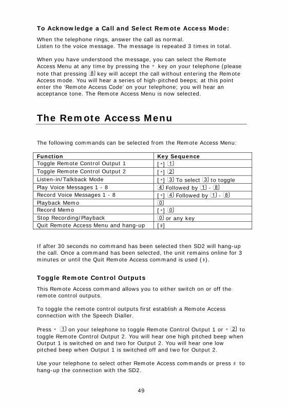
The following commands can be selected from the Remote Access Menu:
Function Key Sequence Toggle Remote Control Output 1 [*] 1 Toggle Remote Control Output 2 [*] 2 Listen-in/Talkback Mode [*] 3 To select 3 to toggle Play Voice Messages 1 - 8 4 Followed by 1 - 8 Record Voice Messages 1 - 8 [*] 4 Followed by 1 - 8 Playback Memo 0 Record Memo [*] 0 Stop Recording/Playback 0 or any key Quit Remote Access Menu and hang-up [#]
If after 30 seconds no command has been selected then SD2 will hang-up the call. Once a command has been selected, the unit remains online for 3 minutes or until the Quit Remote Access command is used (#).
Toggle Remote Control Outputs
This Remote Access command allows you to either switch on or off the remote control outputs. To toggle the remote control outputs first establish a Remote Access connection with the Speech Dialler. Press * 1 on your telephone to toggle Remote Control Output 1 or * 2 to toggle Remote Control Output 2. You will hear one high pitched beep when Output 1 is switched on and two for Output 2. You will hear one low pitched beep when Output 1 is switched off and two for Output 2. Use your telephone to select other Remote Access commands or press # to hang-up the connection with the SD2.
50
Listen-in & Talkback Mode
These Remote Access commands allow you to listen-in and talk to the remote site using your telephone handset.
To Select Listen-in/Talkback Mode:
Establish a Remote Access connection with the Speech Dialler. Press * 3 on your telephone. You can now listen into the premises. Press 3 on your telephone to switch between the Listen-in and Talkback mode. The Listen-in/Talkback mode can also be toggled at site by pressing [ key. When finished press 0 on your telephone to cancel Talkback mode. Use your telephone to select other Remote Access commands or press # to hang-up the connection with the Speech Dialler.
51
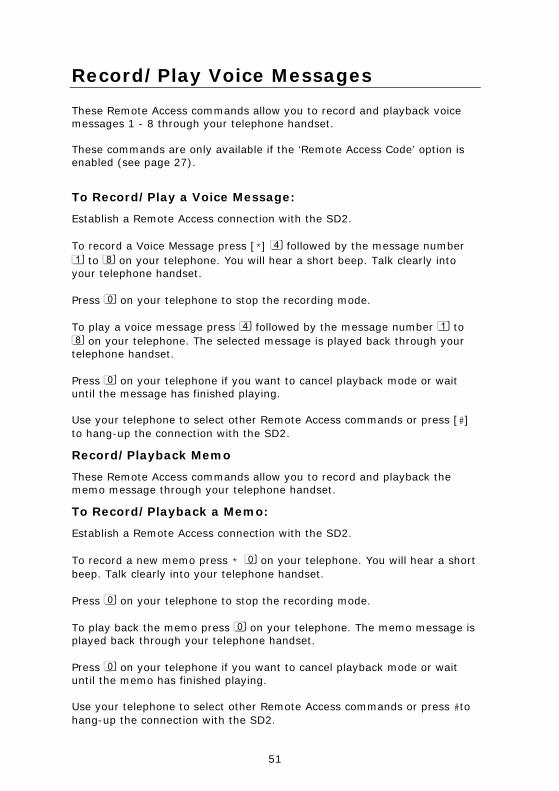
Record/Play Voice Messages
These Remote Access commands allow you to record and playback voice messages 1 - 8 through your telephone handset. These commands are only available if the ‘Remote Access Code’ option is enabled (see page 27).
To Record/Play a Voice Message:
Establish a Remote Access connection with the SD2. To record a Voice Message press [*] 4 followed by the message number 1 to 8 on your telephone. You will hear a short beep. Talk clearly into your telephone handset. Press 0 on your telephone to stop the recording mode. To play a voice message press 4 followed by the message number 1 to 8 on your telephone. The selected message is played back through your telephone handset. Press 0 on your telephone if you want to cancel playback mode or wait until the message has finished playing. Use your telephone to select other Remote Access commands or press [#] to hang-up the connection with the SD2.
Record/Playback Memo
These Remote Access commands allow you to record and playback the memo message through your telephone handset.
To Record/Playback a Memo:
Establish a Remote Access connection with the SD2. To record a new memo press * 0 on your telephone. You will hear a short beep. Talk clearly into your telephone handset. Press 0 on your telephone to stop the recording mode. To play back the memo press 0 on your telephone. The memo message is played back through your telephone handset. Press 0 on your telephone if you want to cancel playback mode or wait until the memo has finished playing. Use your telephone to select other Remote Access commands or press #to hang-up the connection with the SD2.
52
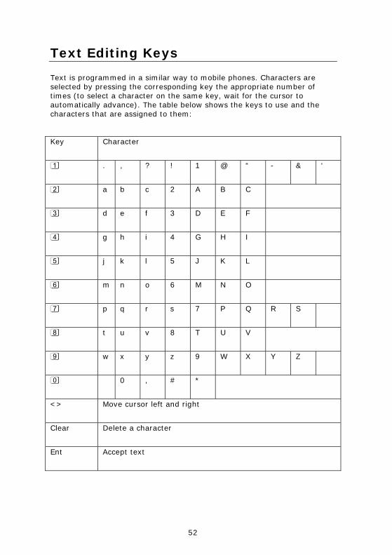
Text Editing Keys
Text is programmed in a similar way to mobile phones. Characters are selected by pressing the corresponding key the appropriate number of times (to select a character on the same key, wait for the cursor to automatically advance). The table below shows the keys to use and the characters that are assigned to them: Key Character
1 . , ? ! 1 @ “ - & ‘
2 a b c 2 A B C
3 d e f 3 D E F
4 g h i 4 G H I
5 j k l 5 J K L
6 m n o 6 M N O
7 p q r s 7 P Q R S
8 t u v 8 T U V
9 w x y z 9 W X Y Z
0 0 , # *
<> Move cursor left and right
Clear Delete a character
Ent Accept text
53
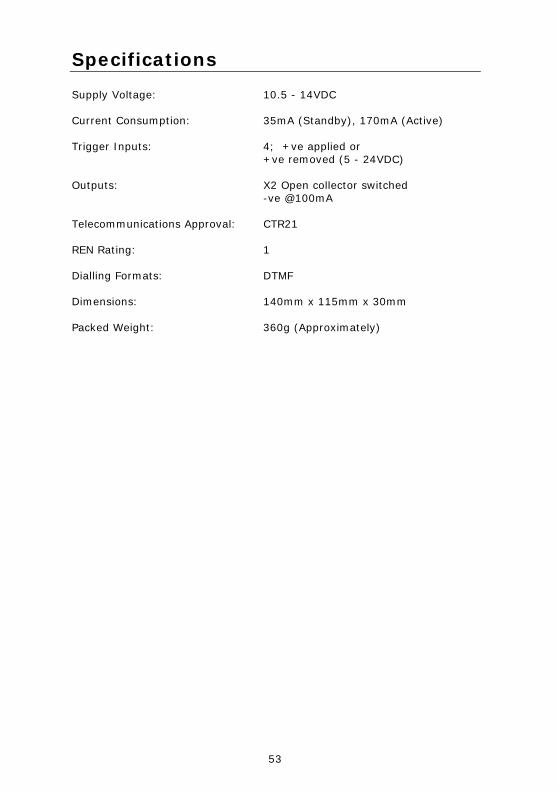
Specifications
Supply Voltage: 10.5 - 14VDC Current Consumption: 35mA (Standby), 170mA (Active) Trigger Inputs: 4; +ve applied or +ve removed (5 - 24VDC) Outputs: X2 Open collector switched -ve @100mA Telecommunications Approval: CTR21 REN Rating: 1 Dialling Formats: DTMF Dimensions: 140mm x 115mm x 30mm Packed Weight: 360g (Approximately)
54
Quick Reference
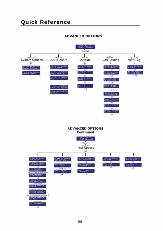
55
Quick Reference
56
Declaration of Conformance Cooper Security Ltd issues this certificate to
certify that the equipment known as:
SD2 Complies with the following directive:
1995/5/EC R&TTE Directive by the application of the following harmonised standards:
BSEN 50130-4 TBR21
BSEN 60950 Signed
Stewart Taylor, Technical Director
Date: 31 March 2004
© Cooper Security Ltd. 2004 Every effort has been made to ensure that the contents of this book are correct. However, neither the authors nor Cooper Security Limited accept any liability for loss or damage caused or alleged to be caused directly or indirectly by this book. The contents of this book are subject to change without notice. Printed and published in the U.K.
Cooper Security Ltd. Security House Vantage Point Business Village Mitcheldean Gloucestershire GL17 0SZ www.scantronic.co.uk Product Support (UK) Tel: +44 (0) 870 757 5400. Available between: 08:15 and 17:00 Monday to Thursday, 08:15 and 12:45 Friday. Emergency service only between 12:45 and 17:00 Friday. Product Support Fax: (01594) 545401 Part Number 496950 Issue 2