Embed Size (px)
DESCRIPTION
Setting Guide for MV Recloser
Citation preview
Circuit breaker control function block description
Document ID: PRELIMINARY VERSION
Budapest, October 2009
Setting guide
to the MV automatic reclosing function
Budapest, December 2014
Setting guide to the medium voltage automatic reclosing function
Version: Preliminary 2/18 17.12.2014
Setting guide version information
Version Date Modification Compiled by
Preliminary 17.12.2014 English version Toth-Petri
Setting guide to the medium voltage automatic reclosing function
Version: Preliminary 3/18 17.12.2014
CONTENTS 1 Parameters of the MV automatic reclosing function............................................................4
1.1 Enumerated parameters ..............................................................................................4 1.1.1 Operation ..............................................................................................................4 1.1.2 EarthFaultRecCycle ..............................................................................................4 1.1.3 PhaseFaultRecCycle ............................................................................................5 1.1.4 Reclosing Started by .............................................................................................5
1.2 Timer parameters .........................................................................................................6 1.2.1 X Dead Time Ph, Y Dead Time EF .......................................................................7 1.2.2 Reclaim Time ........................................................................................................7 1.2.3 Close Command Time ..........................................................................................7 1.2.4 Dynamic Blocking Time ........................................................................................7 1.2.5 Block after Man Close ...........................................................................................8 1.2.6 Action Time ...........................................................................................................9 1.2.7 Start Signal Max Time ...........................................................................................9 1.2.8 DeadTime Max Delay ...........................................................................................9 1.2.9 CB Supervision Time ............................................................................................9 1.2.10 SynCheck Max Time .............................................................................................9 1.2.11 SynSW Max Time .............................................................................................. 10
1.3 Boolean parameters .................................................................................................. 10 1.3.1 CB State Monitoring ........................................................................................... 10 1.3.2 Accelerate N.Trip ............................................................................................... 10 1.3.3 Accelerate FinTrip .............................................................................................. 11
2 The function block of the automatic reclosing function .................................................... 11
2.1 The input signals ....................................................................................................... 11 2.1.1 Block .................................................................................................................. 12 2.1.2 Protection Start .................................................................................................. 12 2.1.3 AutoReclosing Start ........................................................................................... 12 2.1.4 PhaseFault Start ................................................................................................ 12 2.1.5 Manual Close ..................................................................................................... 12 2.1.6 CB Ready ........................................................................................................... 12 2.1.7 CB OPEN position ............................................................................................. 12 2.1.8 SYNC Release ................................................................................................... 12 2.1.9 Dead Time St.Delay ........................................................................................... 12
3 Examples .......................................................................................................................... 13
3.1 Example1: Logic connections of the REC79MV function block ................................ 13
3.2 Example1: Time diagram with two reclosing shots (first unsuccessful, second successful) ........................................................................................................................... 14
3.3 Example2: Timing diagram with two reclosing shots (both unsuccessful) ................ 16
3.4 Example3 Timing diagram with two reclosing shots (both unsuccessful) ................. 17
3.5 Example4 Timing diagram with two reclosing shots (both unsuccessful) ................. 18
Setting guide to the medium voltage automatic reclosing function
Version: Preliminary 4/18 17.12.2014
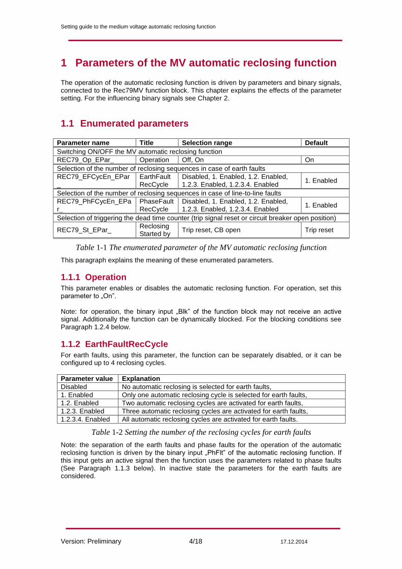
1 Parameters of the MV automatic reclosing function The operation of the automatic reclosing function is driven by parameters and binary signals, connected to the Rec79MV function block. This chapter explains the effects of the parameter setting. For the influencing binary signals see Chapter 2.
1.1 Enumerated parameters
Parameter name Title Selection range Default
Switching ON/OFF the MV automatic reclosing function
REC79_Op_EPar_ Operation Off, On On
Selection of the number of reclosing sequences in case of earth faults
REC79_EFCycEn_EPar_
EarthFaultRecCycle
Disabled, 1. Enabled, 1.2. Enabled, 1.2.3. Enabled, 1.2.3.4. Enabled
1. Enabled
Selection of the number of reclosing sequences in case of line-to-line faults
REC79_PhFCycEn_EPar_
PhaseFaultRecCycle
Disabled, 1. Enabled, 1.2. Enabled, 1.2.3. Enabled, 1.2.3.4. Enabled
1. Enabled
Selection of triggering the dead time counter (trip signal reset or circuit breaker open position)
REC79_St_EPar_ Reclosing Started by
Trip reset, CB open Trip reset
Table 1-1 The enumerated parameter of the MV automatic reclosing function
This paragraph explains the meaning of these enumerated parameters.
1.1.1 Operation
This parameter enables or disables the automatic reclosing function. For operation, set this parameter to „On”. Note: for operation, the binary input „Blk” of the function block may not receive an active signal. Additionally the function can be dynamically blocked. For the blocking conditions see Paragraph 1.2.4 below.
1.1.2 EarthFaultRecCycle
For earth faults, using this parameter, the function can be separately disabled, or it can be configured up to 4 reclosing cycles.
Parameter value Explanation
Disabled No automatic reclosing is selected for earth faults,
1. Enabled Only one automatic reclosing cycle is selected for earth faults,
1.2. Enabled Two automatic reclosing cycles are activated for earth faults,
1.2.3. Enabled Three automatic reclosing cycles are activated for earth faults,
1.2.3.4. Enabled All automatic reclosing cycles are activated for earth faults.
Table 1-2 Setting the number of the reclosing cycles for earth faults
Note: the separation of the earth faults and phase faults for the operation of the automatic reclosing function is driven by the binary input „PhFlt” of the automatic reclosing function. If this input gets an active signal then the function uses the parameters related to phase faults (See Paragraph 1.1.3 below). In inactive state the parameters for the earth faults are considered.
Setting guide to the medium voltage automatic reclosing function
Version: Preliminary 5/18 17.12.2014
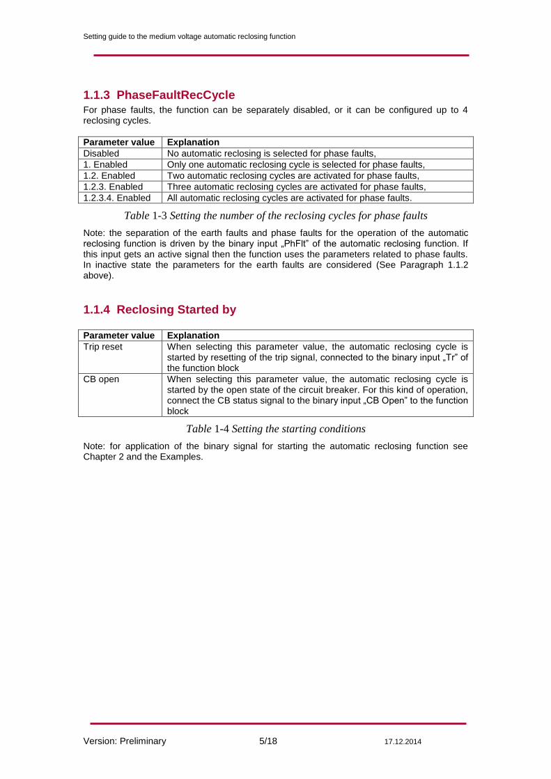
1.1.3 PhaseFaultRecCycle For phase faults, the function can be separately disabled, or it can be configured up to 4 reclosing cycles.
Parameter value Explanation
Disabled No automatic reclosing is selected for phase faults,
1. Enabled Only one automatic reclosing cycle is selected for phase faults,
1.2. Enabled Two automatic reclosing cycles are activated for phase faults,
1.2.3. Enabled Three automatic reclosing cycles are activated for phase faults,
1.2.3.4. Enabled All automatic reclosing cycles are activated for phase faults.
Table 1-3 Setting the number of the reclosing cycles for phase faults
Note: the separation of the earth faults and phase faults for the operation of the automatic reclosing function is driven by the binary input „PhFlt” of the automatic reclosing function. If this input gets an active signal then the function uses the parameters related to phase faults. In inactive state the parameters for the earth faults are considered (See Paragraph 1.1.2 above).
1.1.4 Reclosing Started by
Parameter value Explanation
Trip reset When selecting this parameter value, the automatic reclosing cycle is started by resetting of the trip signal, connected to the binary input „Tr” of the function block
CB open When selecting this parameter value, the automatic reclosing cycle is started by the open state of the circuit breaker. For this kind of operation, connect the CB status signal to the binary input „CB Open” to the function block
Table 1-4 Setting the starting conditions
Note: for application of the binary signal for starting the automatic reclosing function see Chapter 2 and the Examples.
Setting guide to the medium voltage automatic reclosing function
Version: Preliminary 6/18 17.12.2014
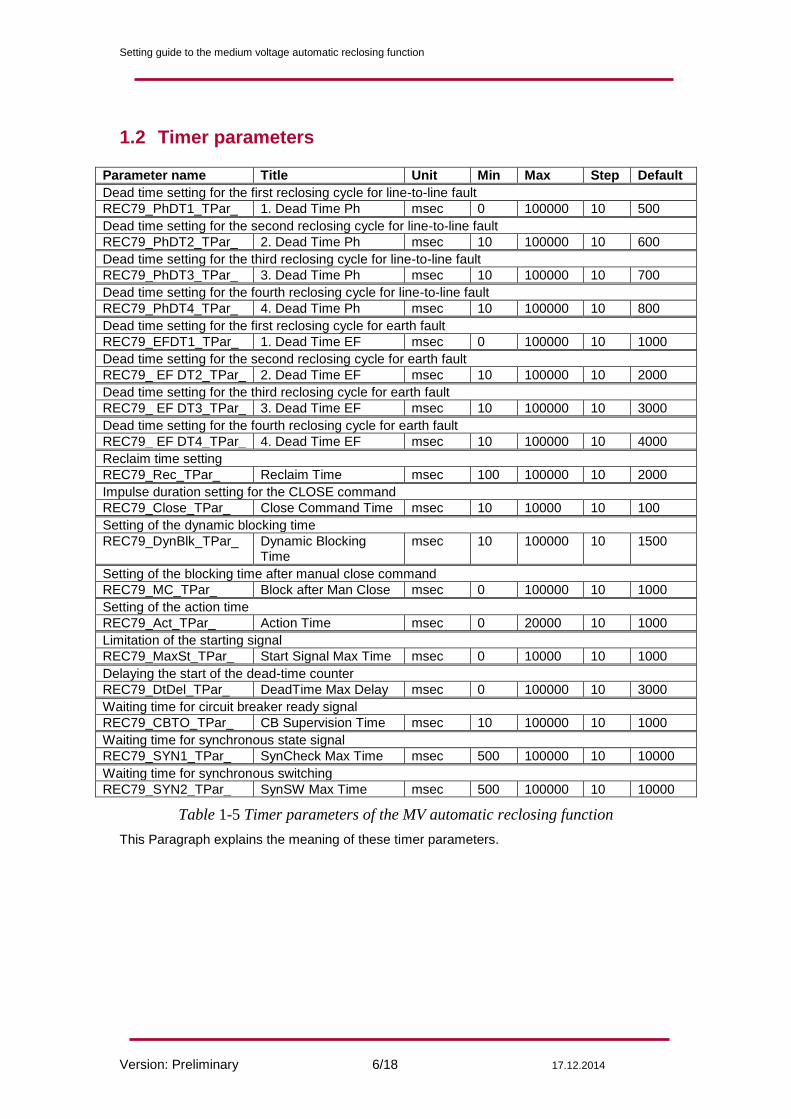
1.2 Timer parameters
Parameter name Title Unit Min Max Step Default
Dead time setting for the first reclosing cycle for line-to-line fault
REC79_PhDT1_TPar_ 1. Dead Time Ph msec 0 100000 10 500
Dead time setting for the second reclosing cycle for line-to-line fault
REC79_PhDT2_TPar_ 2. Dead Time Ph msec 10 100000 10 600
Dead time setting for the third reclosing cycle for line-to-line fault
REC79_PhDT3_TPar_ 3. Dead Time Ph msec 10 100000 10 700
Dead time setting for the fourth reclosing cycle for line-to-line fault
REC79_PhDT4_TPar_ 4. Dead Time Ph msec 10 100000 10 800
Dead time setting for the first reclosing cycle for earth fault
REC79_EFDT1_TPar_ 1. Dead Time EF msec 0 100000 10 1000
Dead time setting for the second reclosing cycle for earth fault
REC79_ EF DT2_TPar_ 2. Dead Time EF msec 10 100000 10 2000
Dead time setting for the third reclosing cycle for earth fault
REC79_ EF DT3_TPar_ 3. Dead Time EF msec 10 100000 10 3000
Dead time setting for the fourth reclosing cycle for earth fault
REC79_ EF DT4_TPar_ 4. Dead Time EF msec 10 100000 10 4000
Reclaim time setting
REC79_Rec_TPar_ Reclaim Time msec 100 100000 10 2000
Impulse duration setting for the CLOSE command
REC79_Close_TPar_ Close Command Time msec 10 10000 10 100
Setting of the dynamic blocking time
REC79_DynBlk_TPar_ Dynamic Blocking Time
msec 10 100000 10 1500
Setting of the blocking time after manual close command
REC79_MC_TPar_ Block after Man Close msec 0 100000 10 1000
Setting of the action time
REC79_Act_TPar_ Action Time msec 0 20000 10 1000
Limitation of the starting signal
REC79_MaxSt_TPar_ Start Signal Max Time msec 0 10000 10 1000
Delaying the start of the dead-time counter
REC79_DtDel_TPar_ DeadTime Max Delay msec 0 100000 10 3000
Waiting time for circuit breaker ready signal
REC79_CBTO_TPar_ CB Supervision Time msec 10 100000 10 1000
Waiting time for synchronous state signal
REC79_SYN1_TPar_ SynCheck Max Time msec 500 100000 10 10000
Waiting time for synchronous switching
REC79_SYN2_TPar_ SynSW Max Time msec 500 100000 10 10000
Table 1-5 Timer parameters of the MV automatic reclosing function
This Paragraph explains the meaning of these timer parameters.
Setting guide to the medium voltage automatic reclosing function
Version: Preliminary 7/18 17.12.2014
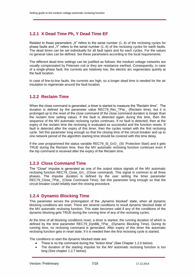
1.2.1 X Dead Time Ph, Y Dead Time EF Related to these parameters „X” refers to the serial number (1..4) of the reclosing cycles for phase faults and „Y” refers to the serial number (1..4) of the reclosing cycles for earth faults. The dead times can be set individually for all fault types and for each cycles. For the values no general rules can be defined. Set these parameters according to the local requirements. The different dead time settings can be justified as follows: the medium voltage networks are usually compensated by Petersen coil or they are resistance earthed. Consequently, in case of a single-phase fault, the currents are relatively low, the electric arc regenerates quickly at the fault location. In case of line-to-line faults, the currents are high, so a longer dead time is needed for the air insulation to regenerate around the fault location.
1.2.2 Reclaim Time
When the close command is generated, a timer is started to measure the “Reclaim time”. The duration is defined by the parameter value REC79_Rec_TPar_ (Reclaim time), but it is prolonged up to the reset of the close command (if the close command duration is longer than the reclaim time setting value). If the fault is detected again during this time, then the sequence of the MV automatic reclosing cycles continues. If no fault is detected, then at the expiry of the reclaim time the reclosing is evaluated as successful and the function resets. If fault is detected after the expiry of this timer, then the cycles restart with the first reclosing cycle. Set this parameter long enough so that the closing time of the circuit breaker and up to one network period of the algorithm starting time should be covered with this time delay. If the user programmed the status variable REC79_St_GrO_ (St: Protection Start) and it gets TRUE during the Reclaim time, then the MV automatic reclosing function continues even if the trip command is received after the expiry of the Reclaim time.
1.2.3 Close Command Time The “Close” impulse is generated as one of the output status signals of the MV automatic reclosing function REC79_Close_GrI_ (Close command). This signal is common to all three phases. The impulse duration is defined by the user setting the timer parameter REC79_Close_TPar_ (Close Command Time). Set this parameter long enough so that the circuit breaker could reliably start the closing procedure.
1.2.4 Dynamic Blocking Time
This parameter serves the prolongation of the „dynamic blocked” state, when all dynamic blocking conditions are reset. There are several conditions to result dynamic blocked state of the MV automatic reclosing function. This state becomes valid if any of the conditions of the dynamic blocking gets TRUE during the running time of any of the reclosing cycles. At the time of all blocking conditions reset, a timer is started, the running duration of which is defined by the time parameter REC79_DynBlk_TPar_ (Dynamic Blocking Time). During its running time, no reclosing command is generated. After expiry of this timer the automatic reclosing function gets in reset state. If it is needed then the first reclosing cycle is started. The conditions to start the dynamic blocked state are:
There is no trip command during the “Action time” (See Chapter 1.2.6 below).
The duration of the starting impulse for the MV automatic reclosing function is too long (See chapter 1.2.7 below).
Setting guide to the medium voltage automatic reclosing function
Version: Preliminary 8/18 17.12.2014
If no “CB ready” signal is received at the intended time of reclosing command (See Paragraph 1.2.9 below)
The dead time is prolonged further then the preset parameter value REC79_DtDel_TPar_ (DeadTime Max.Delay) (See Paragraph 1.2.8 below).
The waiting time for the “SYNC Release” signal is too long (See Paragraph 1.2.10 and 1.2.11)
After the final trip command.
In case of a manual close command (See chapter 1.2.5 below) or a manual open command (if the status variable REC79_CBOpen_GrO_ (CB OPEN) gets TRUE) without REC79_Tr_GrO_ (AutoReclosing Start)).
In case of a general block, i.e. the device is blocked. In a dynamic blocked state, the REC79_Blocked_GrI_ (Blocked) status signal is TRUE.
1.2.5 Block after Man Close
This parameter defines the duration of the blocked state due to manual close command. This state of manual close command is signaled by the binary variable REC79_ManCl_GrO_ (Manual Close). The conditions are defined by the user applying the graphic logic editor. This signal is usually assigned to a dedicated binary input. After a manual close command, the MV automatic reclosing function enters “Not Ready” state for the time period defined by parameter REC79_MC_TPar_ (Block after Man.Close). The role of this delay time is to prevent starting the reclosing cycles if the manual close command is switching onto fault. Set this parameter long enough so that the closing time of the circuit breaker and up to one network period of the algorithm starting time should be covered with this time delay. The “Not Ready” state can be the consequence also of several other conditions: This state becomes valid if any of the conditions of the blocking get TRUE outside the running time of the reclosing cycles.
Reclosing is disabled by the parameter REC79_Op_EPar_ (Operation) if it is selected to “Off”. (See Paragraph 1.1.1 above);
No reclosing cycles are selected by the parameters REC79_EFCycEn_EPar_ (Earth Fault Rec.Cycle) and REC79_PhFCycEn_EPar_ (PhaseFault Rec.Cycle) if it is set to “Disabled” (See Paragraphs 1.1.2 and 1.1.3);
The circuit breaker is not ready for operation: the result of the graphic programming of the binary variable REC79_CBRdy_GrO_ (CB Ready) is FALSE. (See Paragraph 0 below);
After a manual close command (Described in this paragraph) for the defined time span;
If the parameter REC79_CBState_BPar_ (CB State Monitoring) is set to TRUE and the circuit breaker is in Open state, i.e., the value of the REC79_CBOpen_GrO_ (CB OPEN position) status variable gets TRUE;
The starting signal for automatic reclosing is selected by parameter REC79_St_EPar_ (Reclosing started by) to be “CB open” and the circuit breaker is in Open state;
In case of a general block (the device is blocked, see Paragraph 1.2.4 above). In a “Not ready” state, the REC79_Blocked_GrI_ (Blocked) status signal is TRUE. If the manual close command is received during the running time of any of the cycles, then the MV automatic reclosing function enters “Dynamic blocked” state and resets. For dynamic blocked state, see Paragraph 1.2.4 above.
Setting guide to the medium voltage automatic reclosing function
Version: Preliminary 9/18 17.12.2014
1.2.6 Action Time
The user can compose a binary status variable to indicate the start of the protection functions, the operation of which is related to the MV automatic reclosing function. This status variable is REC79_St_GrO_ (Protection Start). This signal starts the “Action time”, the duration of which is defined by the preset parameter value REC79_Act_TPar_ (Action time). During the running time, the MV automatic reclosing function waits for the trip command. If no trip command is received, then the MV automatic reclosing function enters “Dynamic blocked” state. For dynamic blocked state, see Paragraph 1.2.4 above. Set this parameter long enough to cover the delay time of any protection functions (time delay between starting and trip command generation) assigned to start automatic reclosing.
1.2.7 Start Signal Max Time The MV automatic reclosing function gets the trip commands of the protection functions intended to trigger the reclosing function. The conditions for detecting the triggered state of the protection functions are defined by the user applying the graphic logic editor. The binary input status variable to be programmed is: REC79_Tr_GrO_ (Tr). This signal starts a dedicated timer, the elapsed time of which is compared to the preset parameter value REC79_MaxSt_TPar_ (Start Signal Max.Time). After expiry of this timer, the function gets in “Dynamic blocked” state. For dynamic blocked state, see Paragraph 1.2.4 above. Set this parameter in correlation of the breaker failure protection function (if it is applied).
1.2.8 DeadTime Max Delay In the base case, the dead time counter of any reclosing cycle is started by the starting signal (See Chapter 1.1.4) but starting can be delayed. The delay is activated if the value of the REC79_DtDel_GrO_ (Dead Time St.Delay) status signal is TRUE. The conditions are defined by the user applying the graphic logic editor. This delay is limited by the timer parameter REC79_DtDel_TPar_ (DeadTime Max.Delay). Set this parameter in consideration of the remote end fault clearing time.
1.2.9 CB Supervision Time
At the moment of generating the close command, the circuit breaker must be ready for operation, which is signaled via binary input REC79_CBRdy_GrO_ (CB Ready). The preset parameter value REC79_CBTO_TPar_ (CB Supervision time) decides how long the MV automatic reclosing function is allowed to wait at the end of the dead time for this signal. If the signal is not received during this dead time extension, then the MV automatic reclosing function terminates and after a “dynamic blocking time” (depending on the preset parameter value REC79_DynBlk_TPar_ (Dynamic Blocking time)) the function resets. Set this delay long enough so that the circuit breaker gets sufficient time to accumulate energy for the subsequent possible trip command.
1.2.10 SynCheck Max Time
Reclosing is possible only if the conditions required by the “synchro-check” function are fulfilled. This state is signaled by the binary variable REC79_SynRel_GrO_ (SYNC Release). The conditions are defined by the user applying the graphic logic editor. The MV automatic reclosing function waits for a pre-programmed time for this signal. This time is defined by the user as parameter value REC79_SYN1_TPar_ (SyncCheck Max Time). If the “SYNC Release” signal is not received during the running time of this timer, then the “synchronous switch” operation is started (See Paragraph 1.2.11 below) and the signal REC79_ClReq_GrI_ (CloseRequ.SynSwitch) is generated. Set this time delay long enough to assure recognition of the synchronous state of the voltage at both sides of the circuit breaker.
Setting guide to the medium voltage automatic reclosing function
Version: Preliminary 10/18 17.12.2014
1.2.11 SynSW Max Time If the conditions of the synchronous state are not fulfilled, another timer starts. This waiting time is defined by the user as parameter value REC79_SYN2_TPar_ (SySW Max.Time). This separate function controls the generation of the close command in case of relatively rotating voltage vectors on both sides of the open circuit breaker to make contact at the synchronous state of the rotating vectors. For this calculation, the closing time of the circuit breaker must be defined. Set this parameter long enough to allow the rotating vectors to reach the synchron position. This mode of operation is indicated by the output variable REC79_ClReq_GrI_ (CloseRequ. SynSwitch). If no switching is possible during the running time of this timer, then the MV automatic reclosing function enters “Dynamic blocked” state and resets. For dynamic blocked state, see Paragraph 1.2.4 above.
1.3 Boolean parameters
Parameter name Title Default Explanation
REC79_CBState_BPar_ CB State Monitoring
0 Enable CB state monitoring for “Not Ready” state
REC79_Acc1_BPar_ Accelerate 1.Trip
0 Accelerate trip command starting cycle 1
REC79_Acc2_BPar_ Accelerate 2.Trip
0 Accelerate trip command starting cycle 2
REC79_Acc3_BPar_ Accelerate 3.Trip
0 Accelerate trip command starting cycle 3
REC79_Acc4_BPar_ Accelerate 4.Trip
0 Accelerate trip command starting cycle 4
REC79_Acc5_BPar_ Accelerate FinTrip
0 Accelerate final trip command
Table 1-6 Boolean parameters of the MV automatic reclosing function
This paragraph explains the meaning of these boolean parameters.
1.3.1 CB State Monitoring
Enable CB state monitoring for “Not Ready” state. There are several conditions that must be satisfied before the MV automatic reclosing function enters “Not Ready” state. See Paragraph 1.2.5 above.
1.3.2 Accelerate N.Trip
If the reclosing results switch onto fault then the trip command can be accelerated in each cycle. Here “N.” is for the serial number of the cycles. Depending on this binary parameter setting, the automatic reclosing function can accelerate trip commands of the individual reclosing cycles. This means that the output “TrAcc” of the function block gets active for the first starting state of the protection function or at the end of the dead time of the running cycle, if the dedicated parameter enables acceleration. This signal needs user-programmed graphic logic to generate the accelerated trip command.
Setting guide to the medium voltage automatic reclosing function
Version: Preliminary 11/18 17.12.2014
1.3.3 Accelerate FinTrip
The final trip command can also be accelerated. Depending on this binary parameter setting, the automatic reclosing function can accelerate the final trip command. This means that the output “TrAcc” of the function gets active for the first starting state of the protection function or at the end of the dead time of the running cycle, if the dedicated parameter enables acceleration. This signal needs user-programmed graphic logic to generate the accelerated trip command.
2 The function block of the automatic reclosing function
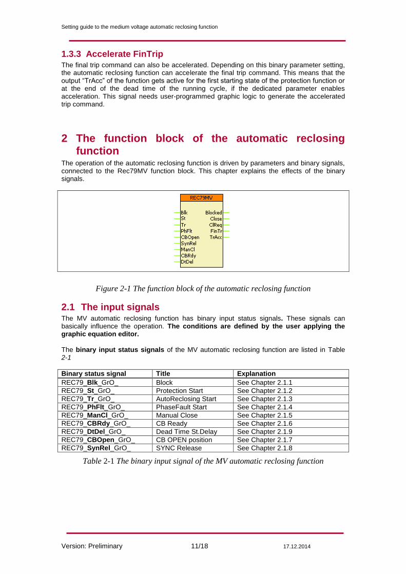
The operation of the automatic reclosing function is driven by parameters and binary signals, connected to the Rec79MV function block. This chapter explains the effects of the binary signals.
Figure 2-1 The function block of the automatic reclosing function
2.1 The input signals The MV automatic reclosing function has binary input status signals. These signals can basically influence the operation. The conditions are defined by the user applying the graphic equation editor. The binary input status signals of the MV automatic reclosing function are listed in Table 2-1
Binary status signal Title Explanation
REC79_Blk_GrO_ Block See Chapter 2.1.1
REC79_St_GrO_ Protection Start See Chapter 2.1.2
REC79_Tr_GrO_ AutoReclosing Start See Chapter 2.1.3
REC79_PhFlt_GrO_ PhaseFault Start See Chapter 2.1.4
REC79_ManCl_GrO_ Manual Close See Chapter 2.1.5
REC79_CBRdy_GrO_ CB Ready See Chapter 2.1.6
REC79_DtDel_GrO_ Dead Time St.Delay See Chapter 2.1.9
REC79_CBOpen_GrO_ CB OPEN position See Chapter 2.1.7
REC79_SynRel_GrO_ SYNC Release See Chapter 2.1.8
Table 2-1 The binary input signal of the MV automatic reclosing function
Setting guide to the medium voltage automatic reclosing function
Version: Preliminary 12/18 17.12.2014
2.1.1 Block The function can be switched Off /On using the parameter REC79_Op_EPar_ (Operation). The user can also block the MV automatic reclosing function applying the graphic logic editor. The binary status variable to be programmed is REC79_Blk_GrO_ (Block). Additionally, if the device is generally blocked, then the MV automatic reclosing function is also blocked.
2.1.2 Protection Start
If the user programmed the status variable REC79_St_GrO_ (St: Protection Start) and it gets TRUE during the “Reclaim time”, then the MV automatic reclosing function continues even if the trip command is received after the expiry of the “Reclaim time”.
2.1.3 AutoReclosing Start
Connect here the trip command of the protection functions, assigned to start the automatic reclosing function. The cycles can start, if this signal resets and the “Reclosing Started by” enumerated parameter is set to “Trip reset” (See Paragraph 1.1.4).
2.1.4 PhaseFault Start
The separation of the earth faults and phase faults for the operation of the automatic reclosing function is driven by the binary input „PhFlt” (PhaseFault Start) of the automatic reclosing function. If this input gets an active signal then the function uses the parameters related to phase faults (See Paragraph 1.1.3). In inactive state the parameters for the earth faults are considered.
2.1.5 Manual Close Connect here the manual close command, which is usually a dedicated binary input of the device. For a fault after manual close command the function does not start automatic reclosing cycles.
2.1.6 CB Ready Connect here the CB ready signal, which is usually a dedicated binary input of the device. If the circuit breaker is not ready for the possible subsequent trip command at the moment of the intended reclosing, then reclosing is not performed. See also Paragraph 1.2.9. If this function is not applied, connect this input to steady TRUE.
2.1.7 CB OPEN position If the binary parameter REC79_CBState_BPar_ (CB State Monitoring) is set to TRUE and the circuit breaker is in Open state, i.e., the value of the REC79_CBOpen_GrO_ (CB OPEN position) status variable gets TRUE then the function gets in “Not Ready” state.
2.1.8 SYNC Release Connect the signal of synchron state supervision function here. If this function is not applied, connect this input to steady TRUE.
2.1.9 Dead Time St.Delay
In the base case, the dead time counter of any reclosing cycle is started by the starting signal (See Chapter 1.1.4) but starting can be delayed. The delay is activated if the value of the REC79_DtDel_GrO_ (Dead Time St.Delay) status signal is TRUE. This delay is limited by the timer parameter REC79_DtDel_TPar_ (DeadTime Max.Delay).
Setting guide to the medium voltage automatic reclosing function
Version: Preliminary 13/18 17.12.2014
3 Examples
3.1 Example1: Logic connections of the REC79MV function block
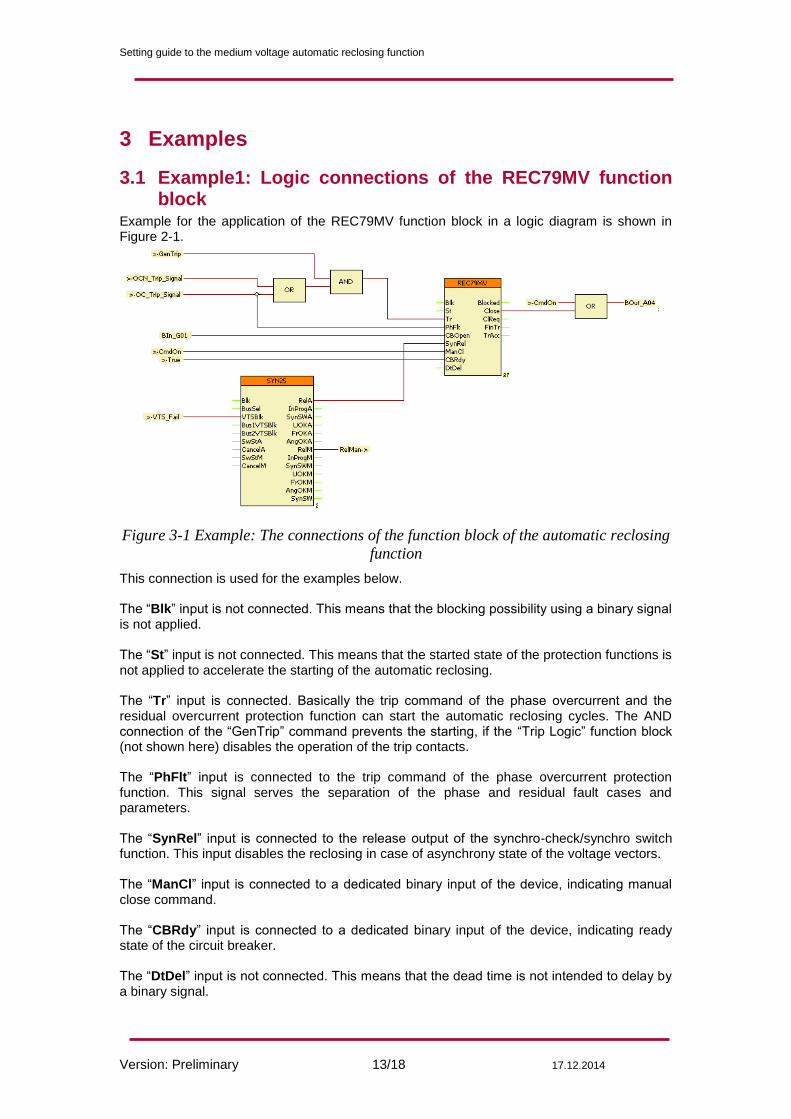
Example for the application of the REC79MV function block in a logic diagram is shown in Figure 2-1.
Figure 3-1 Example: The connections of the function block of the automatic reclosing
function
This connection is used for the examples below. The “Blk” input is not connected. This means that the blocking possibility using a binary signal is not applied. The “St” input is not connected. This means that the started state of the protection functions is not applied to accelerate the starting of the automatic reclosing. The “Tr” input is connected. Basically the trip command of the phase overcurrent and the residual overcurrent protection function can start the automatic reclosing cycles. The AND connection of the “GenTrip” command prevents the starting, if the “Trip Logic” function block (not shown here) disables the operation of the trip contacts. The “PhFlt” input is connected to the trip command of the phase overcurrent protection function. This signal serves the separation of the phase and residual fault cases and parameters. The “SynRel” input is connected to the release output of the synchro-check/synchro switch function. This input disables the reclosing in case of asynchrony state of the voltage vectors. The “ManCl” input is connected to a dedicated binary input of the device, indicating manual close command. The “CBRdy” input is connected to a dedicated binary input of the device, indicating ready state of the circuit breaker. The “DtDel” input is not connected. This means that the dead time is not intended to delay by a binary signal.
Setting guide to the medium voltage automatic reclosing function
Version: Preliminary 14/18 17.12.2014
3.2 Example1: Time diagram with two reclosing shots (first unsuccessful, second successful)
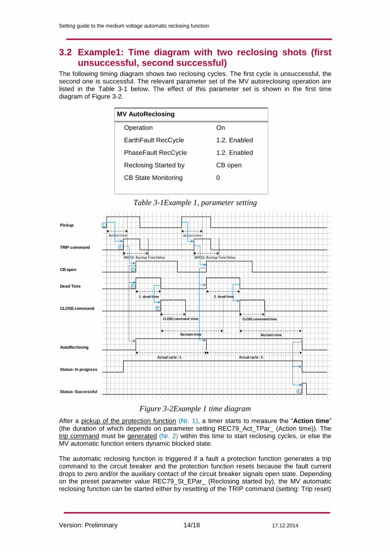
The following timing diagram shows two reclosing cycles. The first cycle is unsuccessful, the second one is successful. The relevant parameter set of the MV autoreclosing operation are listed in the Table 3-1 below. The effect of this parameter set is shown in the first time diagram of Figure 3-2.
MV AutoReclosing
Operation On
EarthFault RecCycle 1.2. Enabled
PhaseFault RecCycle 1.2. Enabled
Reclosing Started by CB open
CB State Monitoring 0
Table 3-1Example 1, parameter setting
Pickup
TRIP command
CB open
Dead Time
CLOSE command
AutoReclosing
Status: In progress
Status: Successful
Action time
BRF50: Backup Time Delay
1. dead time
CLOSE command time
Action time
2. dead time
CLOSE command time
BRF50: Backup Time Delay
Actual cycle : 1. Actual cycle : 2.
Reclaim time Reclaim time
4.
3.
2.
1.
6.
5.
Figure 3-2Example 1 time diagram
After a pickup of the protection function (Nr. 1), a timer starts to measure the “Action time” (the duration of which depends on parameter setting REC79_Act_TPar_ (Action time)). The trip command must be generated (Nr. 2) within this time to start reclosing cycles, or else the MV automatic function enters dynamic blocked state. The automatic reclosing function is triggered if a fault a protection function generates a trip command to the circuit breaker and the protection function resets because the fault current drops to zero and/or the auxiliary contact of the circuit breaker signals open state. Depending on the preset parameter value REC79_St_EPar_ (Reclosing started by), the MV automatic reclosing function can be started either by resetting of the TRIP command (setting: Trip reset)
Setting guide to the medium voltage automatic reclosing function
Version: Preliminary 15/18 17.12.2014
or by the binary signal indicating the open state of the circuit breaker (Nr. 3) (setting: CB open) – in the above example, the “Reclosing started by” parameter is set: “CB Open”. According to the preset parameter values, either of these two conditions starts the timer for counting the „Dead time” (Nr. 4). For all four reclosing cycles, separate dead times can be defined for line-to-line faults and for earth faults. The different dead time settings can be justified as follows: the medium voltage networks are usually compensated by Petersen coil or they are resistance earthed. Consequently, in case of a single-phase fault, the currents are relatively low, the electric arc regenerates quickly at the fault location. In case of line-to-line faults, the currents are high, so a longer dead time is needed for the air insulation to regenerate around the fault location. At the end of the dead time the MV automatic reclosing function generates a close command automatically (Nr. 5). The “Close command” impulse is generated as one of the output status signals of the MV automatic reclosing function REC79_Close_GrI_ (Close command). This signal is common to all three phases. The impulse duration is defined by the user setting the timer parameter REC79_Close_TPar_ (Close command time). When the close command is generated, a timer is started to measure the “Reclaim time”. The duration is defined by the parameter value REC79_Rec_TPar_ (Reclaim time), but it is prolonged up to the reset of the close command (if the close command duration is longer than the reclaim time set). If the fault is detected again during this time, then the sequence of the MV automatic reclosing cycles continues, the above example showing this case. If no fault is detected, then at the expiry of the reclaim time the reclosing is evaluated as successful and the function resets. If a fault is detected after the expiry of this timer, then the cycles restart with the first reclosing cycle. (If the user programmed the status variable REC79_St_GrO_ (Protection Start) and it gets TRUE during the Reclaim time, then the MV automatic reclosing function continues even if the trip command is received after the expiry of the Reclaim time.) After the second reclosing cycle no pickup is detected within the reclaim time, the MV auto reclosing function enters “Successful” state (Nr. 6). The MV automatic reclosing cycle resets and a new fault will start the procedure with the first cycle again.
Setting guide to the medium voltage automatic reclosing function
Version: Preliminary 16/18 17.12.2014
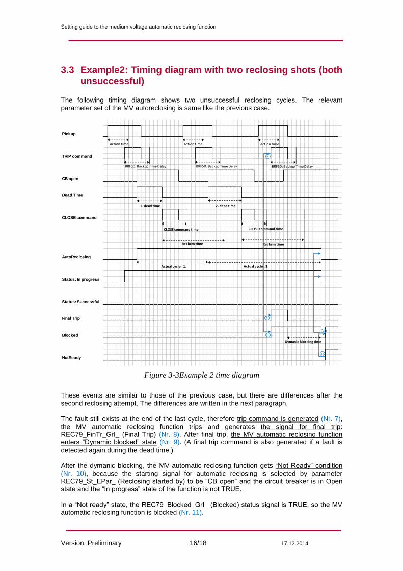
3.3 Example2: Timing diagram with two reclosing shots (both unsuccessful)
The following timing diagram shows two unsuccessful reclosing cycles. The relevant parameter set of the MV autoreclosing is same like the previous case.
Pickup
TRIP command
CB open
Dead Time
CLOSE command
AutoReclosing
Status: In progress
Status: Successful
Final Trip
Blocked
NotReady
Action time
BRF50: Backup Time Delay
1. dead time
CLOSE command time
Action time
2. dead time
CLOSE command time
BRF50: Backup Time Delay
Actual cycle : 1. Actual cycle : 2.
Reclaim time Reclaim time
Action time
BRF50: Backup Time Delay
Dymanic Blocking time
7.
8.
9.
10.
11.
Figure 3-3Example 2 time diagram
These events are similar to those of the previous case, but there are differences after the second reclosing attempt. The differences are written in the next paragraph. The fault still exists at the end of the last cycle, therefore trip command is generated (Nr. 7), the MV automatic reclosing function trips and generates the signal for final trip: REC79_FinTr_GrI_ (Final Trip) (Nr. 8). After final trip, the MV automatic reclosing function enters “Dynamic blocked” state (Nr. 9). (A final trip command is also generated if a fault is detected again during the dead time.) After the dymanic blocking, the MV automatic reclosing function gets “Not Ready” condition (Nr. 10), because the starting signal for automatic reclosing is selected by parameter REC79_St_EPar_ (Reclosing started by) to be “CB open” and the circuit breaker is in Open state and the “In progress” state of the function is not TRUE. In a “Not ready” state, the REC79_Blocked_GrI_ (Blocked) status signal is TRUE, so the MV automatic reclosing function is blocked (Nr. 11).
Setting guide to the medium voltage automatic reclosing function
Version: Preliminary 17/18 17.12.2014
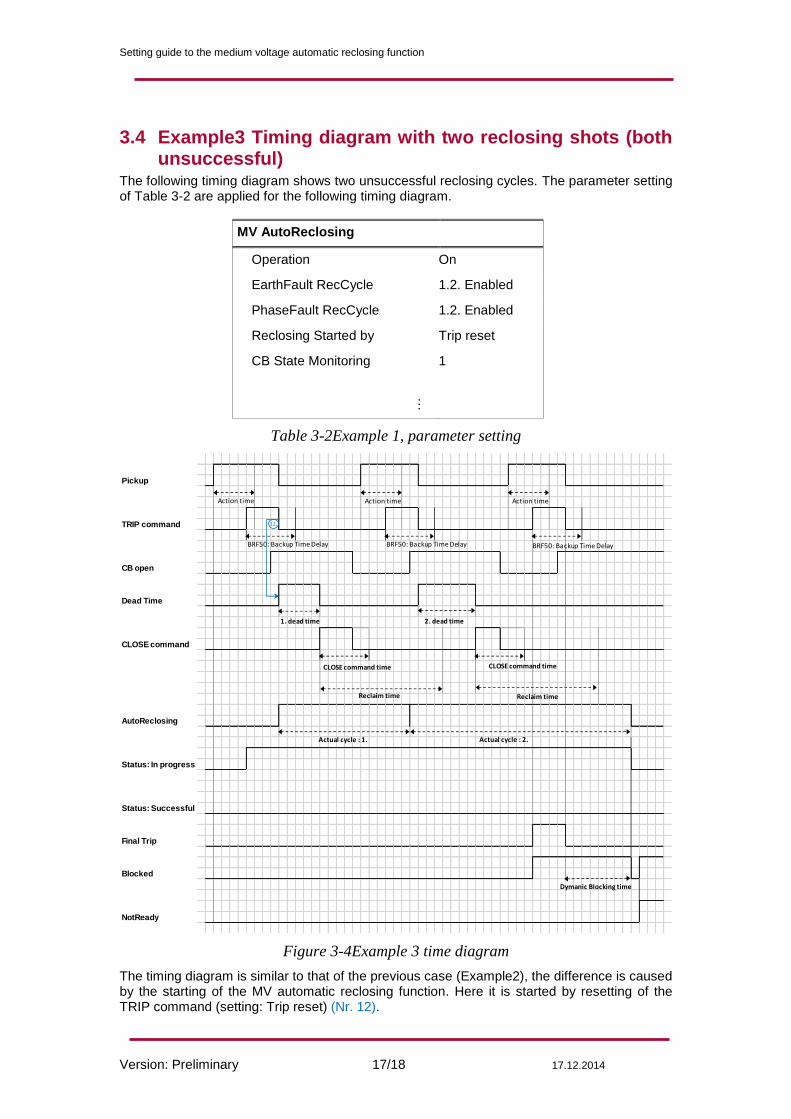
3.4 Example3 Timing diagram with two reclosing shots (both unsuccessful)
The following timing diagram shows two unsuccessful reclosing cycles. The parameter setting of Table 3-2 are applied for the following timing diagram.
MV AutoReclosing
Operation On
EarthFault RecCycle 1.2. Enabled
PhaseFault RecCycle 1.2. Enabled
Reclosing Started by Trip reset
CB State Monitoring 1 …
Table 3-2Example 1, parameter setting
Pickup
TRIP command
CB open
Dead Time
CLOSE command
AutoReclosing
Status: In progress
Status: Successful
Final Trip
Blocked
NotReady
Action time
BRF50: Backup Time Delay
1. dead time
CLOSE command time
Action time
2. dead time
CLOSE command time
BRF50: Backup Time Delay
Actual cycle : 1. Actual cycle : 2.
Reclaim time Reclaim time
Action time
BRF50: Backup Time Delay
Dymanic Blocking time
12.
Figure 3-4Example 3 time diagram
The timing diagram is similar to that of the previous case (Example2), the difference is caused by the starting of the MV automatic reclosing function. Here it is started by resetting of the TRIP command (setting: Trip reset) (Nr. 12).
Setting guide to the medium voltage automatic reclosing function
Version: Preliminary 18/18 17.12.2014
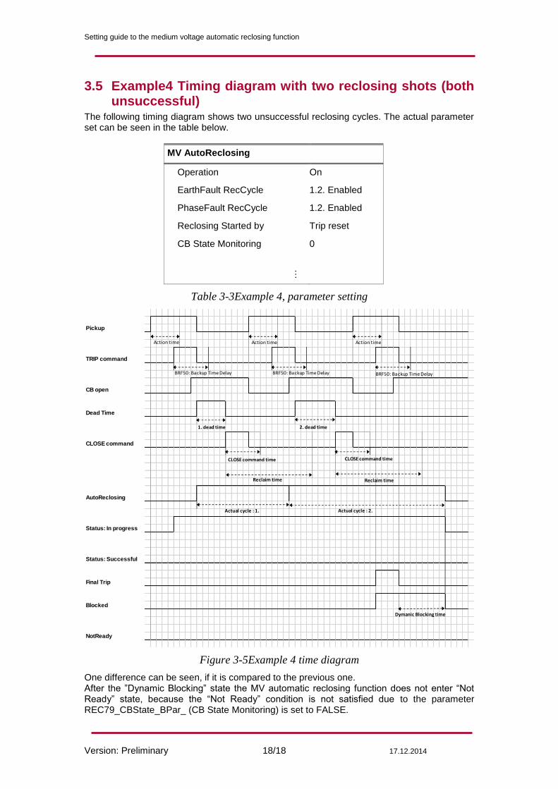
3.5 Example4 Timing diagram with two reclosing shots (both unsuccessful)
The following timing diagram shows two unsuccessful reclosing cycles. The actual parameter set can be seen in the table below.
MV AutoReclosing
Operation On
EarthFault RecCycle 1.2. Enabled
PhaseFault RecCycle 1.2. Enabled
Reclosing Started by Trip reset
CB State Monitoring 0
…
Table 3-3Example 4, parameter setting
Pickup
TRIP command
CB open
Dead Time
CLOSE command
AutoReclosing
Status: In progress
Status: Successful
Final Trip
Blocked
NotReady
Action time
BRF50: Backup Time Delay
1. dead time
CLOSE command time
Action time
2. dead time
CLOSE command time
BRF50: Backup Time Delay
Actual cycle : 1. Actual cycle : 2.
Reclaim time Reclaim time
Action time
BRF50: Backup Time Delay
Dymanic Blocking time
Figure 3-5Example 4 time diagram
One difference can be seen, if it is compared to the previous one. After the ”Dynamic Blocking” state the MV automatic reclosing function does not enter “Not Ready” state, because the “Not Ready” condition is not satisfied due to the parameter REC79_CBState_BPar_ (CB State Monitoring) is set to FALSE.