Embed Size (px)
Citation preview

SERVICE MANUAL
2005.112005.11Ver. 1.0Ver. 1.0
2005.11 Ver.1.0
2005.11 Ver.1.0
© 2005 KONICA MINOLTA BUSINESS TECHNOLOGIES, INC.© 2005 KONICA MINOLTA BUSINESS TECHNOLOGIES, INC.
Printed in JapanPrinted in JapanDD4139CE1-XXXXDD4139CE1-XXXX
Use of this manual should be strictly supervised toavoid disclosure of confidential information.Use of this manual should be strictly supervised toavoid disclosure of confidential information.
magicolor 2480MF
mag
icolo
r 2480MF
THEORY OF OPERATION
THE
OR
Y O
F OP
ER
ATION
THEORY OF OPERATION TOTAL CONTENTS
SAFETY AND IMPORTANT WARNING ITEMS ..............................................................S-1
IMPORTANT NOTICE ................................................................................................S-1
DESCRIPTION ITEMS FOR DANGER, WARNING AND CAUTION .........................S-1
SAFETY WARNINGS .................................................................................................S-2
WARNING INDICATIONS ON THE MACHINE ........................................................S-18
MEASURES TO TAKE IN CASE OF AN ACCIDENT ....................................................S-20
Composition of the service manual ................................................................................. C-1
Notation of the service manual ....................................................................................... C-2
magicolor 2480MF Main UnitOutline ............................................................................................................................ 1
Composition/Operation ................................................................................................... 9
Auto Document Feeder UnitOutline ............................................................................................................................ 1
Composition/Operation ................................................................................................... 3
Lower Feeder UnitOutline ............................................................................................................................ 1
Composition/Operation ................................................................................................... 3
Duplex OptionOutline ............................................................................................................................ 1
Composition/Operation ................................................................................................... 3
i

ii

SAFETY AND IMPORTANT WARNING ITEMS
Read carefully the Safety and Important Warning Items described below to understand them before doing service work.
Because of possible hazards to an inexperienced person servicing this product as well as the risk of damage to the product, KONICA MINOLTA BUSINESS TECHNOLOGIES, INC. (hereafter called the KMBT) strongly recommends that all servicing be performed only by KMBT-trained service technicians.Changes may have been made to this product to improve its performance after this Service Manual was printed. Accordingly, KMBT does not warrant, either explicitly or implicitly, that the information contained in this Service Manual is complete and accurate.The user of this Service Manual must assume all risks of personal injury and/or damage to the product while servicing the product for which this Service Manual is intended.Therefore, this Service Manual must be carefully read before doing service work both in the course of technical training and even after that, for performing maintenance and control of the product properly.Keep this Service Manual also for future service.
In this Service Manual, each of three expressions “ DANGER”, “ WARNING”, and “ CAUTION” is defined as follows together with a symbol mark to be used in a limited meaning. When servicing the product, the relevant works (disassembling, reassembling, adjustment, repair, maintenance, etc.) need to be conducted with utmost care.
Symbols used for safety and important warning items are defined as follows:
SAFETY AND IMPORTANT WARNING ITEMS
IMPORTANT NOTICE
DESCRIPTION ITEMS FOR DANGER, WARNING AND CAUTION
DANGER: Action having a high possibility of suffering death or serious injury
WARNING: Action having a possibility of suffering death or serious injury
CAUTION: Action having a possibility of suffering a slight wound, medium trouble, and property damage
:Precaution when servicing the product. General
precautionElectric hazard High
temperature
:Prohibition when servicing the product. General
prohibitionDo not touch with wet hand
Do not disassemble
:Direction when servicing the product. General
instructionUnplug Ground/Earth
S-1
SAFETY AND IMPORTANT WARNING ITEMS
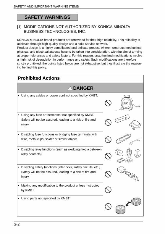
[1] MODIFICATIONS NOT AUTHORIZED BY KONICA MINOLTA BUSINESS TECHNOLOGIES, INC.
KONICA MINOLTA brand products are renowned for their high reliability. This reliability is achieved through high-quality design and a solid service network.Product design is a highly complicated and delicate process where numerous mechanical, physical, and electrical aspects have to be taken into consideration, with the aim of arriving at proper tolerances and safety factors. For this reason, unauthorized modifications involve a high risk of degradation in performance and safety. Such modifications are therefore strictly prohibited. the points listed below are not exhaustive, but they illustrate the reason-ing behind this policy.
SAFETY WARNINGS
Prohibited Actions
DANGER• Using any cables or power cord not specified by KMBT.
• Using any fuse or thermostat not specified by KMBT.
Safety will not be assured, leading to a risk of fire and
injury.
• Disabling fuse functions or bridging fuse terminals with
wire, metal clips, solder or similar object.
• Disabling relay functions (such as wedging media between
relay contacts)
• Disabling safety functions (interlocks, safety circuits, etc.)
Safety will not be assured, leading to a risk of fire and
injury.
• Making any modification to the product unless instructed
by KMBT
• Using parts not specified by KMBT
S-2
SAFETY AND IMPORTANT WARNING ITEMS
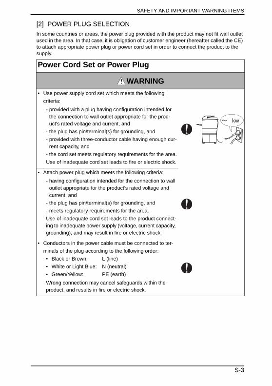
[2] POWER PLUG SELECTION
In some countries or areas, the power plug provided with the product may not fit wall outlet used in the area. In that case, it is obligation of customer engineer (hereafter called the CE) to attach appropriate power plug or power cord set in order to connect the product to the supply.
Power Cord Set or Power Plug
WARNING• Use power supply cord set which meets the following
criteria:
- provided with a plug having configuration intended for the connection to wall outlet appropriate for the prod-uct's rated voltage and current, and
- the plug has pin/terminal(s) for grounding, and
- provided with three-conductor cable having enough cur-rent capacity, and
- the cord set meets regulatory requirements for the area.
Use of inadequate cord set leads to fire or electric shock.
• Attach power plug which meets the following criteria:
- having configuration intended for the connection to wall outlet appropriate for the product's rated voltage and current, and
- the plug has pin/terminal(s) for grounding, and
- meets regulatory requirements for the area.
Use of inadequate cord set leads to the product connect-ing to inadequate power supply (voltage, current capacity, grounding), and may result in fire or electric shock.
• Conductors in the power cable must be connected to ter-
minals of the plug according to the following order:
• Black or Brown: L (line)
• White or Light Blue: N (neutral)
• Green/Yellow: PE (earth)
Wrong connection may cancel safeguards within the product, and results in fire or electric shock.
kw
S-3
SAFETY AND IMPORTANT WARNING ITEMS
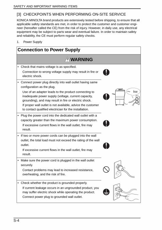
[3] CHECKPOINTS WHEN PERFORMING ON-SITE SERVICE
KONICA MINOLTA brand products are extensively tested before shipping, to ensure that all applicable safety standards are met, in order to protect the customer and customer engi-neer (hereafter called the CE) from the risk of injury. However, in daily use, any electrical equipment may be subject to parts wear and eventual failure. In order to maintain safety and reliability, the CE must perform regular safety checks.
1. Power Supply
Connection to Power Supply
WARNING• Check that mains voltage is as specified.
Connection to wrong voltage supply may result in fire or electric shock.
• Connect power plug directly into wall outlet having same
configuration as the plug.
Use of an adapter leads to the product connecting to inadequate power supply (voltage, current capacity, grounding), and may result in fire or electric shock.
If proper wall outlet is not available, advice the customer to contact qualified electrician for the installation.
• Plug the power cord into the dedicated wall outlet with a
capacity greater than the maximum power consumption.
If excessive current flows in the wall outlet, fire may result.
• If two or more power cords can be plugged into the wall
outlet, the total load must not exceed the rating of the wall
outlet.
If excessive current flows in the wall outlet, fire may result.
• Make sure the power cord is plugged in the wall outlet
securely.
Contact problems may lead to increased resistance, overheating, and the risk of fire.
• Check whether the product is grounded properly.
If current leakage occurs in an ungrounded product, you may suffer electric shock while operating the product.
Connect power plug to grounded wall outlet.
kw
S-4

SAFETY AND IMPORTANT WARNING ITEMS
Power Plug and Cord
WARNING• When using the power cord set (inlet type) that came with
this product, make sure the connector is securely inserted
in the inlet of the product.
When securing measure is provided, secure the cord with
the fixture properly.
If the power cord (inlet type) is not connected to the prod-uct securely, a contact problem may lead to increased resistance, overheating, and risk of fire.
• Check whether the power cord is not stepped on or
pinched by a table and so on.
Overheating may occur there, leading to a risk of fire.
• Check whether the power cord is damaged. Check
whether the sheath is damaged.
If the power plug, cord, or sheath is damaged, replace with a new power cord (with plug and connector on each end) specified by KMBT. Using the damaged power cord may result in fire or electric shock.
• Do not bundle or tie the power cord.
Overheating may occur there, leading to a risk of fire.
• Check whether dust is collected around the power plug
and wall outlet.
Using the power plug and wall outlet without removing dust may result in fire.
• Do not insert the power plug into the wall outlet with a wet
hand.
The risk of electric shock exists.
• When unplugging the power cord, grasp the plug, not the
cable.
The cable may be broken, leading to a risk of fire and electric shock.
S-5

SAFETY AND IMPORTANT WARNING ITEMS
2. Installation Requirements
Wiring
WARNING• Never use multi-plug adapters to plug multiple power cords
in the same outlet.
If used, the risk of fire exists.
• When an extension cord is required, use a specified one.
Current that can flow in the extension cord is limited, so
using a too long extension cord may result in fire.
Do not use an extension cable reel with the cable taken up. Fire may result.
Prohibited Installation Places
WARNING• Do not place the product near flammable materials or vola-
tile materials that may catch fire.
A risk of fire exists.
• Do not place the product in a place exposed to water such
as rain.
A risk of fire and electric shock exists.
When not Using the Product for a long time
WARNING• When the product is not used over an extended period of
time (holidays, etc.), switch it off and unplug the power
cord.
Dust collected around the power plug and outlet may cause fire.
S-6
SAFETY AND IMPORTANT WARNING ITEMS
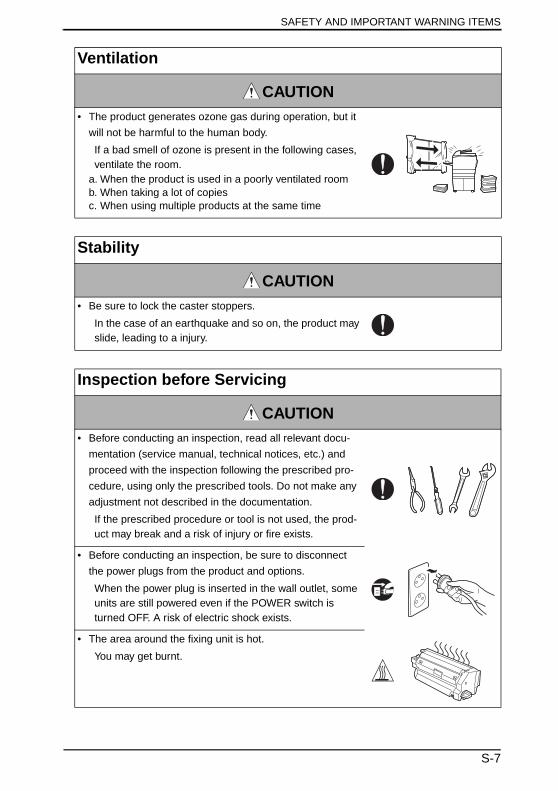
Ventilation
CAUTION• The product generates ozone gas during operation, but it
will not be harmful to the human body.
If a bad smell of ozone is present in the following cases, ventilate the room.
a. When the product is used in a poorly ventilated roomb. When taking a lot of copiesc. When using multiple products at the same time
Stability
CAUTION• Be sure to lock the caster stoppers.
In the case of an earthquake and so on, the product may slide, leading to a injury.
Inspection before Servicing
CAUTION• Before conducting an inspection, read all relevant docu-
mentation (service manual, technical notices, etc.) and
proceed with the inspection following the prescribed pro-
cedure, using only the prescribed tools. Do not make any
adjustment not described in the documentation.
If the prescribed procedure or tool is not used, the prod-uct may break and a risk of injury or fire exists.
• Before conducting an inspection, be sure to disconnect
the power plugs from the product and options.
When the power plug is inserted in the wall outlet, some units are still powered even if the POWER switch is turned OFF. A risk of electric shock exists.
• The area around the fixing unit is hot.
You may get burnt.
S-7
SAFETY AND IMPORTANT WARNING ITEMS
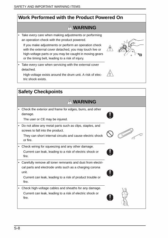
Work Performed with the Product Powered On
WARNING• Take every care when making adjustments or performing
an operation check with the product powered.
If you make adjustments or perform an operation check with the external cover detached, you may touch live or high-voltage parts or you may be caught in moving gears or the timing belt, leading to a risk of injury.
• Take every care when servicing with the external cover
detached.
High-voltage exists around the drum unit. A risk of elec-tric shock exists.
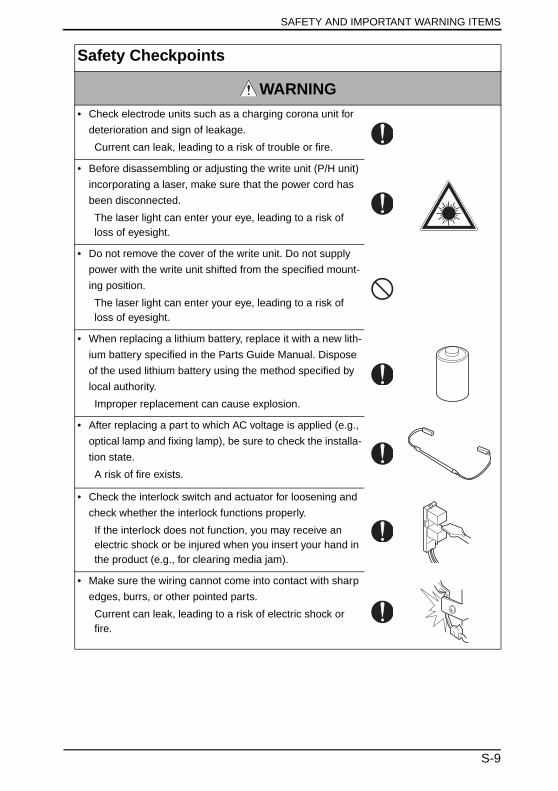
Safety Checkpoints
WARNING• Check the exterior and frame for edges, burrs, and other
damage.
The user or CE may be injured.
• Do not allow any metal parts such as clips, staples, and
screws to fall into the product.
They can short internal circuits and cause electric shock or fire.
• Check wiring for squeezing and any other damage.
Current can leak, leading to a risk of electric shock or fire.
• Carefully remove all toner remnants and dust from electri-
cal parts and electrode units such as a charging corona
unit.
Current can leak, leading to a risk of product trouble or fire.
• Check high-voltage cables and sheaths for any damage.
Current can leak, leading to a risk of electric shock or fire.
S-8
SAFETY AND IMPORTANT WARNING ITEMS
• Check electrode units such as a charging corona unit for
deterioration and sign of leakage.
Current can leak, leading to a risk of trouble or fire.
• Before disassembling or adjusting the write unit (P/H unit)
incorporating a laser, make sure that the power cord has
been disconnected.
The laser light can enter your eye, leading to a risk of loss of eyesight.
• Do not remove the cover of the write unit. Do not supply
power with the write unit shifted from the specified mount-
ing position.
The laser light can enter your eye, leading to a risk of loss of eyesight.
• When replacing a lithium battery, replace it with a new lith-
ium battery specified in the Parts Guide Manual. Dispose
of the used lithium battery using the method specified by
local authority.
Improper replacement can cause explosion.
• After replacing a part to which AC voltage is applied (e.g.,
optical lamp and fixing lamp), be sure to check the installa-
tion state.
A risk of fire exists.
• Check the interlock switch and actuator for loosening and
check whether the interlock functions properly.
If the interlock does not function, you may receive an electric shock or be injured when you insert your hand in the product (e.g., for clearing media jam).
• Make sure the wiring cannot come into contact with sharp
edges, burrs, or other pointed parts.
Current can leak, leading to a risk of electric shock or fire.
Safety Checkpoints
WARNING
S-9

SAFETY AND IMPORTANT WARNING ITEMS
• Make sure that all screws, components, wiring, connec-
tors, etc. that were removed for safety check and mainte-
nance have been reinstalled in the original location. (Pay
special attention to forgotten connectors, pinched cables,
forgotten screws, etc.)
A risk of product trouble, electric shock, and fire exists.
Safety Checkpoints
WARNING
Handling of Consumables
WARNING• Toner and developer are not harmful substances, but care
must be taken not to breathe excessive amounts or let the
substances come into contact with eyes, etc. It may be
stimulative.
If the substances get in the eye, rinse with plenty of water immediately. When symptoms are noticeable, consult a physician.
• Never throw the used cartridge and toner into fire.
You may be burned due to dust explosion.
Handling of Service Materials
CAUTION• Unplug the power cord from the wall outlet.
Drum cleaner (isopropyl alcohol) and roller cleaner (ace-tone-based) are highly flammable and must be handled with care. A risk of fire exists.
• Do not replace the cover or turn the product ON before
any solvent remnants on the cleaned parts have fully
evaporated.
A risk of fire exists.
S-10

SAFETY AND IMPORTANT WARNING ITEMS
• Use only a small amount of cleaner at a time and take
care not to spill any liquid. If this happens, immediately
wipe it off.
A risk of fire exists.
• When using any solvent, ventilate the room well.
Breathing large quantities of organic solvents can lead to
discomfort.
Handling of Service Materials
CAUTION
S-11
SAFETY AND IMPORTANT WARNING ITEMS
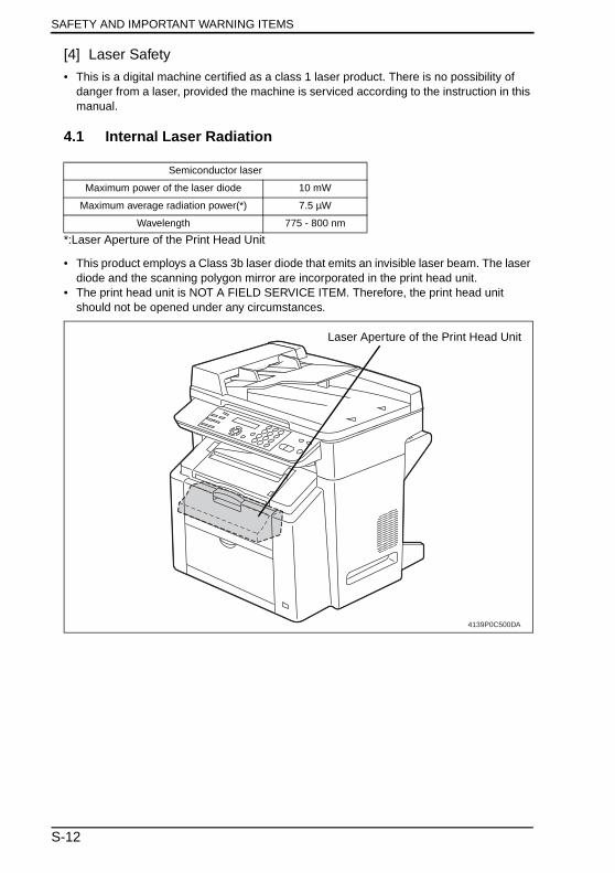
[4] Laser Safety
• This is a digital machine certified as a class 1 laser product. There is no possibility of danger from a laser, provided the machine is serviced according to the instruction in this manual.
4.1 Internal Laser Radiation
*:Laser Aperture of the Print Head Unit
• This product employs a Class 3b laser diode that emits an invisible laser beam. The laser diode and the scanning polygon mirror are incorporated in the print head unit.
• The print head unit is NOT A FIELD SERVICE ITEM. Therefore, the print head unit should not be opened under any circumstances.
Semiconductor laser
Maximum power of the laser diode 10 mW
Maximum average radiation power(*) 7.5 µW
Wavelength 775 - 800 nm
4139P0C500DA
Laser Aperture of the Print Head Unit
S-12
SAFETY AND IMPORTANT WARNING ITEMS
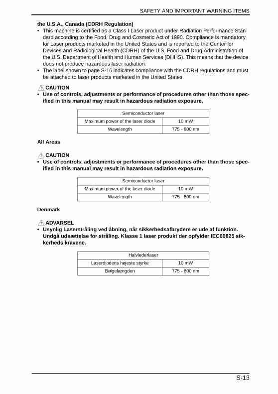
the U.S.A., Canada (CDRH Regulation)• This machine is certified as a Class I Laser product under Radiation Performance Stan-
dard according to the Food, Drug and Cosmetic Act of 1990. Compliance is mandatory for Laser products marketed in the United States and is reported to the Center for Devices and Radiological Health (CDRH) of the U.S. Food and Drug Administration of the U.S. Department of Health and Human Services (DHHS). This means that the device does not produce hazardous laser radiation.
• The label shown to page S-16 indicates compliance with the CDRH regulations and must be attached to laser products marketed in the United States.
CAUTION• Use of controls, adjustments or performance of procedures other than those spec-
ified in this manual may result in hazardous radiation exposure.
All Areas
CAUTION• Use of controls, adjustments or performance of procedures other than those spec-
ified in this manual may result in hazardous radiation exposure.
Denmark
ADVARSEL• Usynlig Laserstråling ved åbning, når sikkerhedsafbrydere er ude af funktion.
Undgå udsættelse for stråling. Klasse 1 laser produkt der opfylder IEC60825 sik-kerheds kravene.
Semiconductor laser
Maximum power of the laser diode 10 mW
Wavelength 775 - 800 nm
Semiconductor laser
Maximum power of the laser diode 10 mW
Wavelength 775 - 800 nm
Halvlederlaser
Laserdiodens højeste styrke 10 mW
Bølgelængden 775 - 800 nm
S-13
SAFETY AND IMPORTANT WARNING ITEMS
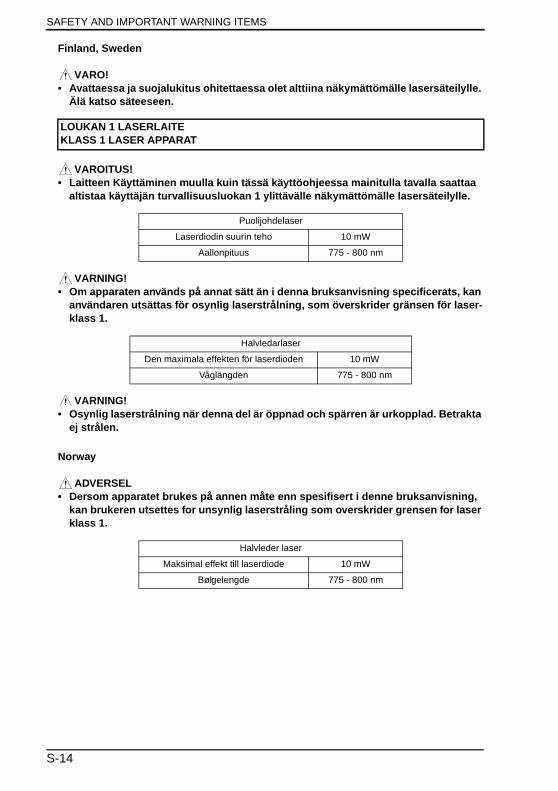
Finland, Sweden
VARO!• Avattaessa ja suojalukitus ohitettaessa olet alttiina näkymättömälle lasersäteilylle.
Älä katso säteeseen.
VAROITUS!• Laitteen Käyttäminen muulla kuin tässä käyttöohjeessa mainitulla tavalla saattaa
altistaa käyttäjän turvallisuusluokan 1 ylittävälle näkymättömälle lasersäteilylle.
VARNING!• Om apparaten används på annat sätt än i denna bruksanvisning specificerats, kan
användaren utsättas för osynlig laserstrålning, som överskrider gränsen för laser-klass 1.
VARNING!• Osynlig laserstrålning när denna del är öppnad och spärren är urkopplad. Betrakta
ej strålen.
Norway
ADVERSEL• Dersom apparatet brukes på annen måte enn spesifisert i denne bruksanvisning,
kan brukeren utsettes for unsynlig laserstråling som overskrider grensen for laser klass 1.
LOUKAN 1 LASERLAITEKLASS 1 LASER APPARAT
Puolijohdelaser
Laserdiodin suurin teho 10 mW
Aallonpituus 775 - 800 nm
Halvledarlaser
Den maximala effekten för laserdioden 10 mW
Våglängden 775 - 800 nm
Halvleder laser
Maksimal effekt till laserdiode 10 mW
Bølgelengde 775 - 800 nm
S-14
SAFETY AND IMPORTANT WARNING ITEMS
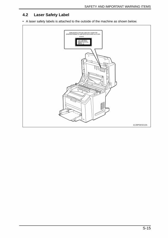
4.2 Laser Safety Label
• A laser safety labels is attached to the outside of the machine as shown below.
4139P0E501DA
COMPLIES WITH 21 CFR 1040.10 AND 1040.11 EXCEPT FORDEVIATIONS PURSUANT TO LASER NOTICE NO.50, DATED JULY 26, 2001.
or/and
S-15
SAFETY AND IMPORTANT WARNING ITEMS
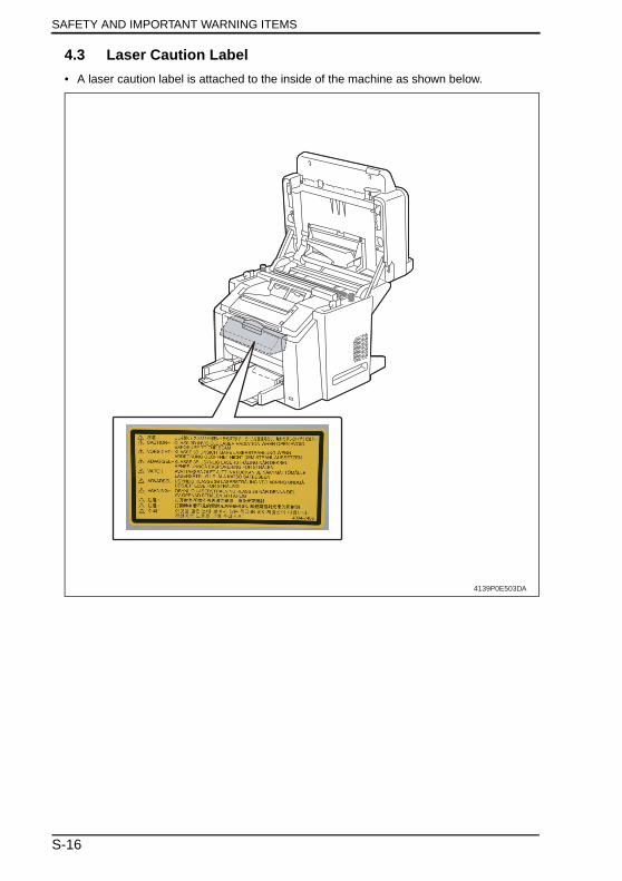
4.3 Laser Caution Label
• A laser caution label is attached to the inside of the machine as shown below.
4139P0E503DA
S-16

SAFETY AND IMPORTANT WARNING ITEMS
4.4 Precautions For Handling The Laser Equipment
• When laser protective goggles are to be used, select ones with a lens conforming to the above specifications.
• When a disassembly job needs to be performed in the laser beam path, such as when working around the printerhead and PC Drum, be sure first to turn the copier OFF.
• If the job requires that the copier be left ON, take off your watch and ring and wear laser protective goggles.
• A highly reflective tool can be dangerous if it is brought into the laser beam path. Use utmost care when handling tools on the user’s premises.
S-17
SAFETY AND IMPORTANT WARNING ITEMS
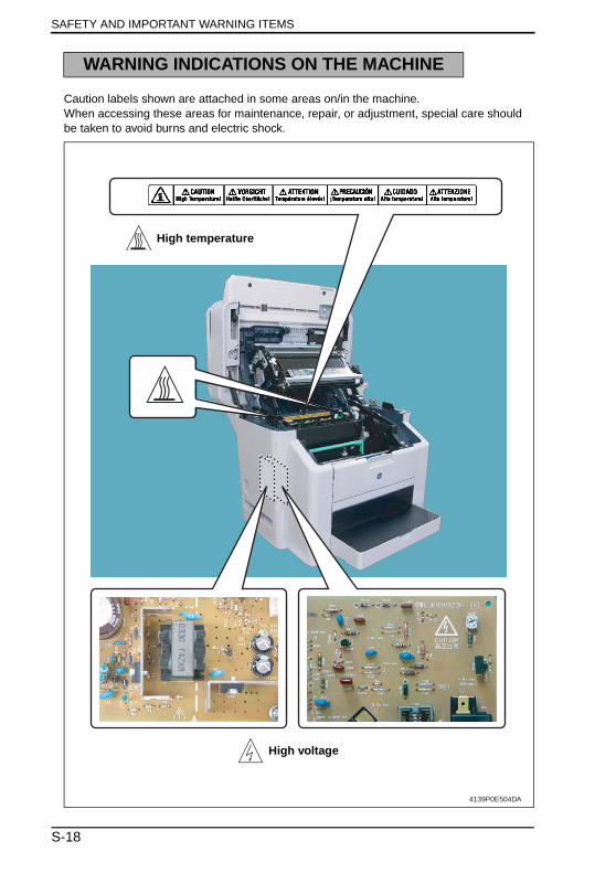
Caution labels shown are attached in some areas on/in the machine.When accessing these areas for maintenance, repair, or adjustment, special care should be taken to avoid burns and electric shock.
WARNING INDICATIONS ON THE MACHINE
4139P0E504DA
High temperature
High voltage
S-18
SAFETY AND IMPORTANT WARNING ITEMS
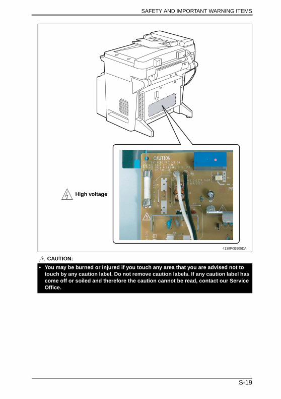
CAUTION:
4139P0E505DA
High voltage
• You may be burned or injured if you touch any area that you are advised not to touch by any caution label. Do not remove caution labels. If any caution label has come off or soiled and therefore the caution cannot be read, contact our Service Office.
S-19

MEASURES TO TAKE IN CASE OF AN ACCIDENT
1. If an accident has occurred, the distributor who has been notified first must immediately take emergency measures to provide relief to affected persons and to prevent further damage.
2. If a report of a serious accident has been received from a customer, an on-site evalua-tion must be carried out quickly and KMBT must be notified.
3. To determine the cause of the accident, conditions and materials must be recorded through direct on-site checks, in accordance with instructions issued by KMBT.
4. For reports and measures concerning serious accidents, follow the regulations speci-fied by every distributor.
MEASURES TO TAKE IN CASE OF AN ACCIDENT
S-20
Composition of the service manualThis service manual consists of Theory of Operation section and Field Service section to
explain the main machine and its corresponding options.
Theory of Operation section gives, as information for the CE to get a full understanding of
the product, a rough outline of the object and role of each function, the relationship
between the electrical system and the mechanical system, and the timing of operation of
each part.
Field Service section gives, as information required by the CE at the site (or at the cus-
tomer’s premise), a rough outline of the service schedule and its details, maintenance
steps, the object and role of each adjustment, error codes and supplementary information.
The basic configuration of each section is as follows. However some options may not be
applied to the following configuration.
<Theory of Operation section>
<Field service section>
OUTLINE: Explanation of system configuration,
product specifications, unit configuration, and paper path
COMPOSITION/OPERATION: Explanation of configuration of each unit,
operating system, and control system
GENERAL: Explanation of system configuration, and product
specifications
MAINTENANCE: Explanation of service schedule, maintenance steps, ser-
vice tools, removal/reinstallation methods of major parts,
and firmware version up method etc.
ADJUSTMENT/SETTING: Explanation of utility mode, service mode, and mechanical
adjustment etc.
TROUBLESHOOTING: Explanation of lists of jam codes and error codes, and
their countermeasures etc.
APPENDIX: Parts layout drawings, connector layout drawings, timing
chart, overall layout drawing are attached.
C-1
Notation of the service manualA. Product nameIn this manual, each of the products is described as follows:
B. Brand nameThe company names and product names mentioned in this manual are the brand name or
the registered trademark of each company.
(1) IC board: Standard printer
(2) magicolor 2480MF: Main body
(3) Microsoft Windows 95: Windows 95
Microsoft Windows 98: Windows 98
Microsoft Windows Me: Windows Me
Microsoft Windows NT 4.0: Windows NT 4.0 or Windows NT
Microsoft Windows 2000: Windows 2000
Microsoft Windows XP: Windows XP
When the description is made in combination of the OS’s mentioned above:
Windows 95/98/Me
Windows NT 4.0/2000
Windows NT/2000/XP
Windows 95/98/Me/ NT/2000/XP
C-2

SERVICE MANUAL
2005.11Ver. 1.0
THEORY OF OPERATION
Main Unitmagicolor 2480MFmagicolor 2480MF
®

Revision historyAfter publication of this service manual, the parts and mechanism may be subject to change forimprovement of their performance. Therefore, the descriptions given in this service manual may not coincide with the actual machine.
When any change has been made to the descriptions in the service manual, a revised version will beissued with a revision mark added as required.
Revision mark:• To indicate clearly a section revised, show to the left of the revised section.
A number within represents the number of times the revision has been made.
• To indicate clearly a section revised, show in the lower outside section of the correspond-ing page. A number within represents the number of times the revision has been made.
NOTERevision marks shown in a page are restricted only to the latest ones with the old ones deleted.
• When a page revised in Ver. 2.0 has been changed in Ver. 3.0: The revision marks for Ver. 3.0 only are shown with those for Ver. 2.0 deleted.
• When a page revised in Ver. 2.0 has not been changed in Ver. 3.0: The revision marks for Ver. 2.0 are left as they are.
11
1
1
2005/11 1.0 — Issue of the first edition
Date Service manual Ver. Revision mark Descriptions of revision
ma
gic
olo
r 2
48
0M
FO
utlin
eC
om
po
sitio
n/O
pe
ratio
n
Theory of Operation Ver. 1.0 Nov. 2005
CONTENTS
magicolor 2480MF Main Unit
Outline1. System configuration............................................................................................... 1
2. Product specifications ............................................................................................. 2
2.1 Built-in Controllers ................................................................................................ 4
3. Center cross section ............................................................................................... 5
4. Paper path............................................................................................................... 6
5. Image creation process........................................................................................... 7
Composition/Operation6. Overall composition................................................................................................. 9
6.1 Operation sequence ............................................................................................. 9
6.2 Control block diagram......................................................................................... 10
7. Scanner Section (IR Section)................................................................................ 11
7.1 Composition........................................................................................................ 11
7.2 Drive ................................................................................................................... 12
7.3 Operation ............................................................................................................ 13
7.3.1 IR Unit Open/Close Mechanism.................................................................. 13
7.3.2 Auto Document Feeder Unit Open/Close.................................................... 15
7.3.3 Original Size Detection ............................................................................... 15
8. Write section (PH section)..................................................................................... 16
8.1 Composition........................................................................................................ 16
8.2 Operation ............................................................................................................ 17
8.2.1 Outline......................................................................................................... 17
8.2.2 Laser exposure process.............................................................................. 17
8.2.3 Laser emission timing ................................................................................. 18
8.2.4 Laser emission area.................................................................................... 18
9. Cartridge section................................................................................................... 19
9.1 Composition........................................................................................................ 19
9.2 Drive ................................................................................................................... 20
9.3 Operation ............................................................................................................ 20
9.3.1 Drum Cartridge (DC) life control ................................................................. 20
9.3.2 Toner Cartridge (TC) life control.................................................................. 21
10. Photo Conductor section....................................................................................... 22
10.1 Composition........................................................................................................ 22
10.2 Drive ................................................................................................................... 22
i
ma
gic
olo
r 2
48
0M
FO
utlin
eC
om
po
sitio
n/O
pe
ratio
nTheory of Operation Ver. 1.0 Nov. 2005
10.3 Operation............................................................................................................ 23
10.3.1 Photo Conductor drive mechanism............................................................. 23
10.3.2 Photo Conductor cleaning mechanism....................................................... 23
11. Charge Corona section ......................................................................................... 24
11.1 Composition ....................................................................................................... 24
11.2 Operation............................................................................................................ 25
11.2.1 Charge Corona Unit ON/OFF control ......................................................... 25
12. Developing section................................................................................................ 26
12.1 Composition ....................................................................................................... 26
12.2 Drive ................................................................................................................... 27
12.2.1 Developing drive control ............................................................................. 28
12.2.2 Toner flow ................................................................................................... 28
12.2.3 Developing bias .......................................................................................... 29
12.2.4 Developing system...................................................................................... 29
12.2.5 Toner Cartridge Rack.................................................................................. 30
13. Image Transfer Section ......................................................................................... 36
13.1 Composition ....................................................................................................... 36
13.1.1 1st transfer section...................................................................................... 36
13.1.2 2nd transfer section .................................................................................... 37
13.2 Drive ................................................................................................................... 38
13.3 Operation............................................................................................................ 38
13.3.1 Transfer Belt cleaning mechanism.............................................................. 38
13.3.2 1st Transfer Roller voltage ON/OFF control ................................................ 42
13.3.3 2nd Transfer Roller pressure/retraction mechanism ................................... 42
13.3.4 2nd Transfer Roller cleaning ....................................................................... 44
13.3.5 Neutralization and separation of paper....................................................... 45
13.3.6 Belt Positioning Sensor............................................................................... 45
13.3.7 ATVC (Auto Transfer Voltage Control)......................................................... 46
14. Toner collecting section......................................................................................... 47
14.1 Composition ....................................................................................................... 47
14.2 Drive ................................................................................................................... 47
14.3 Operation............................................................................................................ 48
14.3.1 Toner collecting mechanism ....................................................................... 48
14.3.2 Waste toner full detection system............................................................... 49
15. Paper feed section ................................................................................................ 50
15.1 Composition ....................................................................................................... 50
15.2 Drive ................................................................................................................... 51
15.3 Operation............................................................................................................ 51
15.3.1 Paper feed control....................................................................................... 51
ii
ma
gic
olo
r 2
48
0M
FO
utlin
eC
om
po
sitio
n/O
pe
ratio
n
Theory of Operation Ver. 1.0 Nov. 2005
15.3.2 Paper feed speed control ............................................................................ 51
15.3.3 Paper feed mechanism ............................................................................... 52
15.3.4 Double feed prevention mechanism............................................................ 53
15.3.5 Paper empty condition detection................................................................. 53
15.3.6 Paper feed retry function............................................................................. 53
16. Conveyance Section/Registration Roller ............................................................... 54
16.1 Composition........................................................................................................ 54
16.2 Drive ................................................................................................................... 55
16.3 Operation ............................................................................................................ 55
16.3.1 Registration Roller control........................................................................... 55
16.3.2 OHP film detection ...................................................................................... 56
16.3.3 Size error detection control ......................................................................... 56
17. Fusing section ....................................................................................................... 57
17.1 Composition........................................................................................................ 57
17.2 Drive ................................................................................................................... 58
17.3 Operation ............................................................................................................ 58
17.3.1 Heating Roller drive control......................................................................... 58
17.3.2 Fusing temperature control ......................................................................... 60
17.3.3 Protection against abnormally high temperature ........................................ 64
17.3.4 PPM control ................................................................................................ 65
18. Paper exit section.................................................................................................. 66
18.1 Composition........................................................................................................ 66
18.2 Drive ................................................................................................................... 67
18.3 Operation ............................................................................................................ 67
18.3.1 Exit Tray Full Detection ............................................................................... 67
19. Image stabilization control..................................................................................... 68
19.1 Overview............................................................................................................. 68
19.2 Operation ............................................................................................................ 69
19.2.1 Leak detection control ................................................................................. 69
19.2.2 AIDC Sensor LED intensity control ............................................................. 69
19.2.3 Reflectance measurement control .............................................................. 69
19.2.4 Control of the maximum amount of toner sticking....................................... 69
19.2.5 Laser intensity adjustment control .............................................................. 69
19.2.6 g correction control ..................................................................................... 69
19.3 Operation timing ................................................................................................. 70
19.4 Operation flow..................................................................................................... 70
20. Other control ......................................................................................................... 71
20.1 Fan control .......................................................................................................... 71
20.1.1 Construction................................................................................................ 71
iii
ma
gic
olo
r 2
48
0M
FO
utlin
eC
om
po
sitio
n/O
pe
ratio
nTheory of Operation Ver. 1.0 Nov. 2005
20.1.2 Control ........................................................................................................ 72
20.2 Temperature/ Humidity Sensor ........................................................................... 73
20.2.1 Composition................................................................................................ 73
iv
Theory of Operation Ver. 1.0 Nov. 2005 1. System configuration
ma
gic
olo
r 2
48
0M
FO
utlin
e
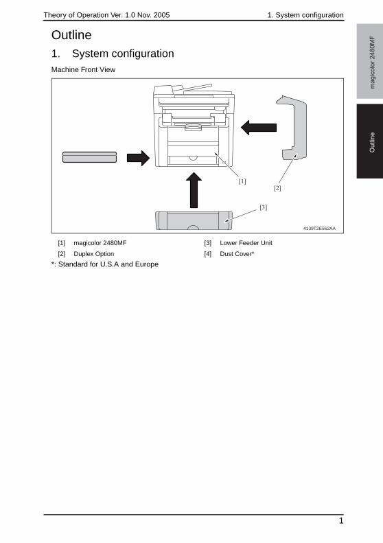
Outline1. System configurationMachine Front View
*: Standard for U.S.A and Europe
[1] magicolor 2480MF [3] Lower Feeder Unit
[2] Duplex Option [4] Dust Cover*
4139T2E562AA
[1][2]
[3]
1
2. Product specifications Theory of Operation Ver. 1.0 Nov. 2005m
ag
ico
lor
24
80
MF
Ou
tlin
e
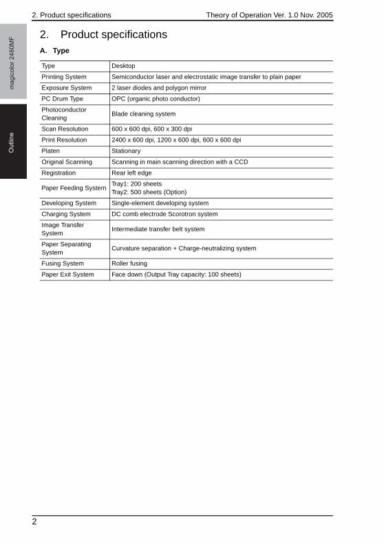
2. Product specificationsA. Type
Type Desktop
Printing System Semiconductor laser and electrostatic image transfer to plain paper
Exposure System 2 laser diodes and polygon mirror
PC Drum Type OPC (organic photo conductor)
Photoconductor Cleaning
Blade cleaning system
Scan Resolution 600 x 600 dpi, 600 x 300 dpi
Print Resolution 2400 x 600 dpi, 1200 x 600 dpi, 600 x 600 dpi
Platen Stationary
Original Scanning Scanning in main scanning direction with a CCD
Registration Rear left edge
Paper Feeding SystemTray1: 200 sheetsTray2: 500 sheets (Option)
Developing System Single-element developing system
Charging System DC comb electrode Scorotron system
Image Transfer System
Intermediate transfer belt system
Paper Separating System
Curvature separation + Charge-neutralizing system
Fusing System Roller fusing
Paper Exit System Face down (Output Tray capacity: 100 sheets)
2
Theory of Operation Ver. 1.0 Nov. 2005 2. Product specifications
ma
gic
olo
r 2
48
0M
FO
utlin
e
B. Functions
C. Maintenance
D. Machine Specifications
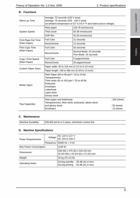
Warm-up TimeAverage: 70 seconds (100 V area)Average: 75 seconds (200 - 240 V area)(at ambient temperature of 23 °C/73.4 °F and rated source voltage)
System Speed
Plain paper 126.78 mm/second
Thick stock 63.39 mm/second
OHP film 42.26 mm/second
First-Page-Out Time(Plain Paper)
Full Color 21 seconds
Monochrome 12 seconds
First Copy Time(Plain Paper)
Full Color 52 seconds
MonochromeNormal Mode: 23 secondsFine Mode: 25 seconds
Copy / Print Speed(Plain Paper)
Full Color 5 pages/minute
Monochrome 20 pages/minute
Custom Paper SizesPaper width: 92 to 216 mm (3 1/2 to 8 1/2 inch)
Paper length: 148 to 356 mm (5 3/4 to 14 inch)
Media Types
Plain Paper (60 to 90 g/m2 / 16 to 24 lb)TransparenciesThick stock (91 to 163 g/m2 / 25 to 40 lb)PostcardsEnvelopesLetterheadLabel stockGlossy stock
Tray Capacities
Plain paper and letterhead : 200 sheetsTransparencies, thick stock, postcards, labels stock, and glossy stock : 50 sheetsEnvelopes : 10 sheets
Machine Durability 200,000 prints or 5 years, whichever comes first
Power RequirementsVoltage:
AC 110 to 127 VAC 220 to 240 V
Frequency: 50/60 Hz ± 3 Hz
Max Power Consumption 1100 W
Dimensions528 (W) x 475 (D) x 531 (H) mm20 3/4 (W) x 18 3/4 (D) x 21 (H) inch
Weight 32 kg (70 1/2 lb)
Operating NoiseDuring standby : 39 dB (A) or lessDuring printing : 53 dB (A) or less
3

2. Product specifications Theory of Operation Ver. 1.0 Nov. 2005m
ag
ico
lor
24
80
MF
Ou
tlin
e
E. Operating Environment
2.1 Built-in Controllers
NOTE• These specifications are subject to change without notice.
Temperature10 °C to 35 °C / 50 °F to 95 °F (with a fluctuation of 10 °C / 18 °F or less per hour)
Humidity 15% to 85% (with a fluctuation of 20% or less per hour)
CPU DC2040 108MHz
Standard Memory 96 MB
Interfaces USB2.0 compliant
OS Compatibility Windows 98SE/Me/2000/XP
4
Theory of Operation Ver. 1.0 Nov. 2005 3. Center cross section
ma
gic
olo
r 2
48
0M
FO
utlin
e
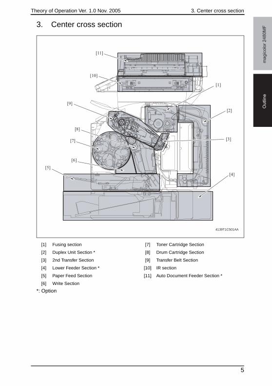
3. Center cross section
*: Option
[1] Fusing section [7] Toner Cartridge Section
[2] Duplex Unit Section * [8] Drum Cartridge Section
[3] 2nd Transfer Section [9] Transfer Belt Section
[4] Lower Feeder Section * [10] IR section
[5] Paper Feed Section [11] Auto Document Feeder Section *
[6] Write Section
4139T1C501AA
[11]
[1]
[2]
[4]
[3]
[6]
[7]
[8]
[9]
[10]
[5]
5
4. Paper path Theory of Operation Ver. 1.0 Nov. 2005m
ag
ico
lor
24
80
MF
Ou
tlin
e
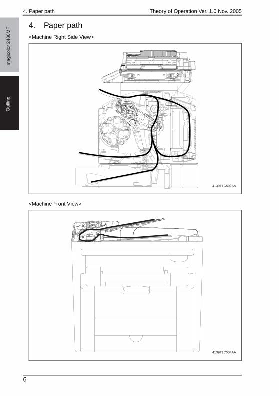
4. Paper path<Machine Right Side View>
<Machine Front View>
4139T1C502AA
4139T1C504AA
6
Theory of Operation Ver. 1.0 Nov. 2005 5. Image creation process
ma
gic
olo
r 2
48
0M
FO
utlin
e
5. Image creation process
4139T1C503AA
[1] CCD (Photoelectric Conversion)
[2] Image Processing Board
[3] Laser Exposure
[4] Photo conductor
[5] Photo Conductor Charging
[6] Developing
[7] 1st Image Transfer
[8] 2nd Image Transfer
[9] Paper Separation
[11] Transfer Belt Cleaning
[12] Fusing
[10] Photo Conductor Cleaning
7
5. Image creation process Theory of Operation Ver. 1.0 Nov. 2005m
ag
ico
lor
24
80
MF
Ou
tlin
e
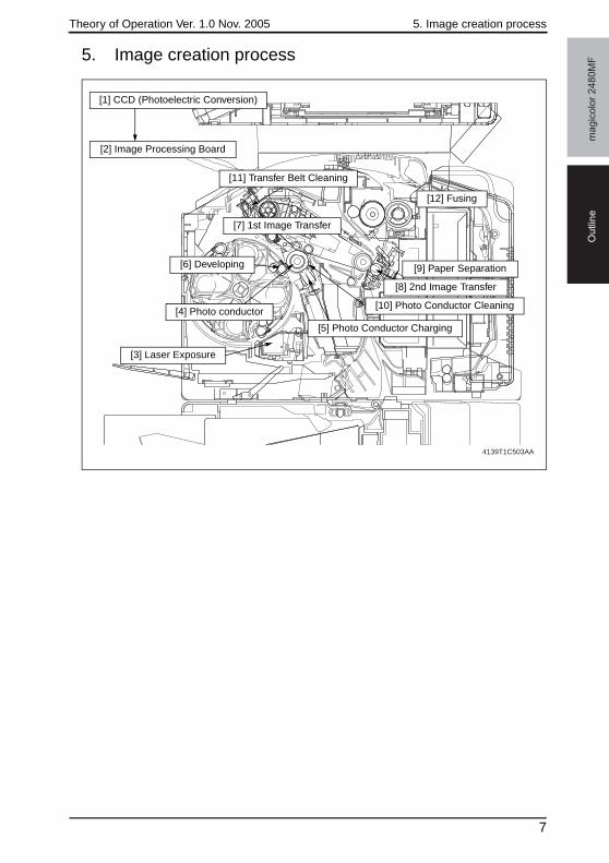
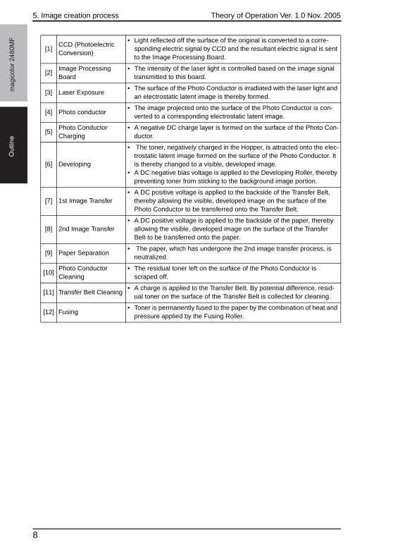
[1]CCD (Photoelectric Conversion)
• Light reflected off the surface of the original is converted to a corre-sponding electric signal by CCD and the resultant electric signal is sent to the Image Processing Board.
[2]Image Processing Board
• The intensity of the laser light is controlled based on the image signal transmitted to this board.
[3] Laser Exposure• The surface of the Photo Conductor is irradiated with the laser light and
an electrostatic latent image is thereby formed.
[4] Photo conductor• The image projected onto the surface of the Photo Conductor is con-
verted to a corresponding electrostatic latent image.
[5]Photo Conductor Charging
• A negative DC charge layer is formed on the surface of the Photo Con-ductor.
[6] Developing
• The toner, negatively charged in the Hopper, is attracted onto the elec-trostatic latent image formed on the surface of the Photo Conductor. It is thereby changed to a visible, developed image.
• A DC negative bias voltage is applied to the Developing Roller, thereby preventing toner from sticking to the background image portion.
[7] 1st Image Transfer• A DC positive voltage is applied to the backside of the Transfer Belt,
thereby allowing the visible, developed image on the surface of the Photo Conductor to be transferred onto the Transfer Belt.
[8] 2nd Image Transfer• A DC positive voltage is applied to the backside of the paper, thereby
allowing the visible, developed image on the surface of the Transfer Belt to be transferred onto the paper.
[9] Paper Separation• The paper, which has undergone the 2nd image transfer process, is
neutralized.
[10]Photo Conductor Cleaning
• The residual toner left on the surface of the Photo Conductor is scraped off.
[11] Transfer Belt Cleaning• A charge is applied to the Transfer Belt. By potential difference, resid-
ual toner on the surface of the Transfer Belt is collected for cleaning.
[12] Fusing• Toner is permanently fused to the paper by the combination of heat and
pressure applied by the Fusing Roller.
8
Theory of Operation Ver. 1.0 Nov. 2005 6. Overall composition
ma
gic
olo
r 2
48
0M
FC
om
po
sitio
n/O
pe
ratio
n
Composition/Operation6. Overall composition
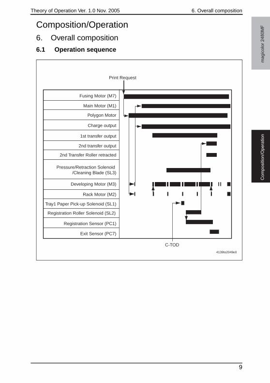
6.1 Operation sequence
Fusing Motor (M7)
Print Request
Main Motor (M1)
Polygon Motor
Charge output
1st transfer output
2nd transfer output
2nd Transfer Roller retracted
Pressure/Retraction Solenoid /Cleaning Blade (SL3)
Developing Motor (M3)
C-TOD
Rack Motor (M2)
Tray1 Paper Pick-up Solenoid (SL1)
Registration Roller Solenoid (SL2)
Registration Sensor (PC1)
Exit Sensor (PC7)
4139to2049e0
9

6. Overall composition Theory of Operation Ver. 1.0 Nov. 2005m
ag
ico
lor
24
80
MF
Co
mp
ositio
n/O
pe
ratio
n
6.2 Control block diagram
4139T2E543AA
Printer Control Board PRCB)
Image Processing Board (IPB)
Write Unit (PH)
Image processing
CPU
OperationPanel
CCD Unit
Scanner Motor
Various IR sensors
IR
Auto DocumentFeeder
Paper Pick-up/transport
Image process
Control System Line
Image Bus Line Fusing Power supply/high voltage
IR Cooling Fan Motor
Lower Feeder Unit
Duplex Unit
IR Unit open/close sensor
DC power supply2
10
Theory of Operation Ver. 1.0 Nov. 2005 7. Scanner Section (IR Section)
ma
gic
olo
r 2
48
0M
FC
om
po
sitio
n/O
pe
ratio
n
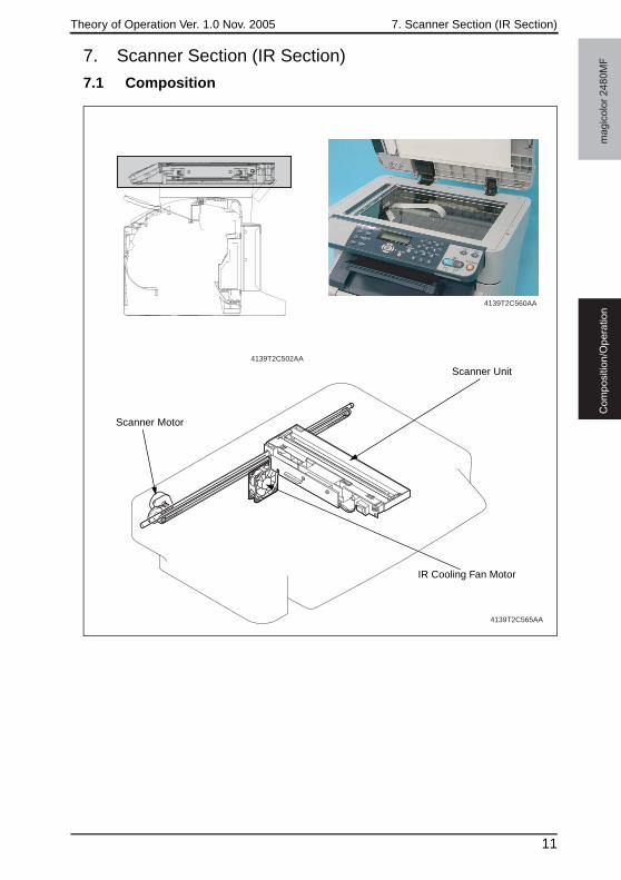
7. Scanner Section (IR Section)
7.1 Composition
4139T2C502AA
4139T2C560AA
4139T2C565AA
Scanner Unit
Scanner Motor
IR Cooling Fan Motor
11
7. Scanner Section (IR Section) Theory of Operation Ver. 1.0 Nov. 2005m
ag
ico
lor
24
80
MF
Co
mp
ositio
n/O
pe
ratio
n
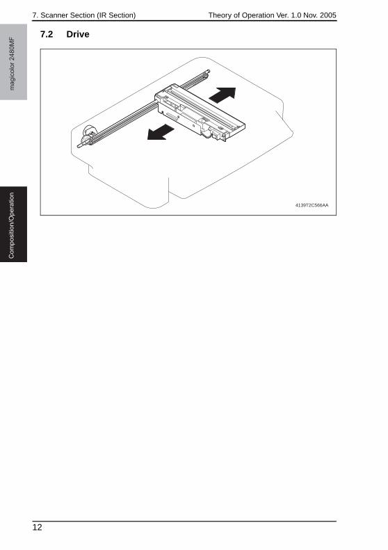
7.2 Drive
4139T2C566AA
12
Theory of Operation Ver. 1.0 Nov. 2005 7. Scanner Section (IR Section)
ma
gic
olo
r 2
48
0M
FC
om
po
sitio
n/O
pe
ratio
n
7.3 Operation
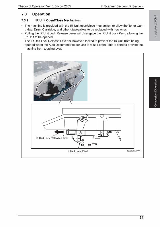
7.3.1 IR Unit Open/Close Mechanism
• The machine is provided with the IR Unit open/close mechanism to allow the Toner Car-tridge, Drum Cartridge, and other disposables to be replaced with new ones.
• Pulling the IR Unit Lock Release Lever will disengage the IR Unit Lock Pawl, allowing the IR Unit to be opened.The IR Unit Lock Release Lever is, however, locked to prevent the IR Unit from being opened when the Auto Document Feeder Unit is raised open. This is done to prevent the machine from toppling over.
4139T2C547AA
IR Unit Lock Release Lever
IR Unit Lock Pawl
13

7. Scanner Section (IR Section) Theory of Operation Ver. 1.0 Nov. 2005m
ag
ico
lor
24
80
MF
Co
mp
ositio
n/O
pe
ratio
n
A. IR Unit open/close operation• Pulling the IR Unit Lock Release Lever will disengage the IR Unit Lock Pawl, allowing the
IR Unit to be opened.
• When the Auto Document Feeder Unit is raised open, the ADF Lever is pushed upward to lock the IR Unit Lock Release Lever, thus preventing the IR Unit from being opened.
4139T2C550AA
IR Unit Lock PawlIR Unit Lock Release Lever
4139T2C548AA
IR Unit in locked conditionIR Unit in unlocked condition
ADF Lever
14
Theory of Operation Ver. 1.0 Nov. 2005 7. Scanner Section (IR Section)
ma
gic
olo
r 2
48
0M
FC
om
po
sitio
n/O
pe
ratio
n
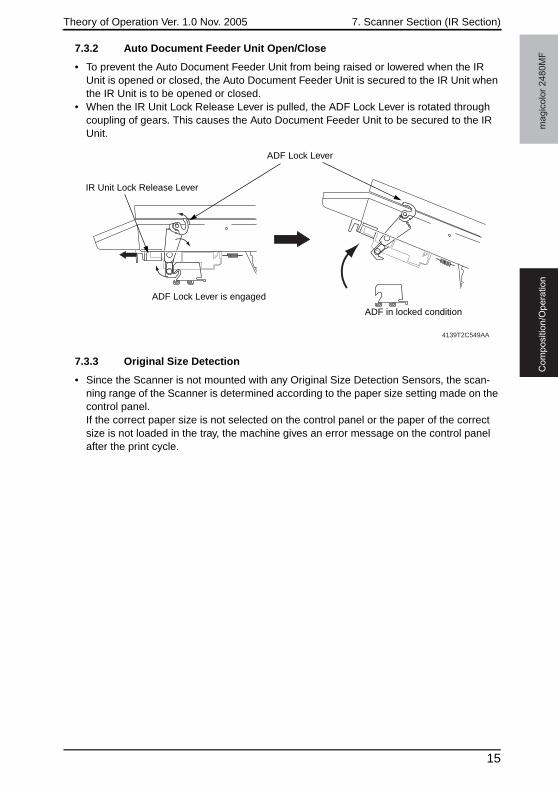
7.3.2 Auto Document Feeder Unit Open/Close
• To prevent the Auto Document Feeder Unit from being raised or lowered when the IR Unit is opened or closed, the Auto Document Feeder Unit is secured to the IR Unit when the IR Unit is to be opened or closed.
• When the IR Unit Lock Release Lever is pulled, the ADF Lock Lever is rotated through coupling of gears. This causes the Auto Document Feeder Unit to be secured to the IR Unit.
7.3.3 Original Size Detection
• Since the Scanner is not mounted with any Original Size Detection Sensors, the scan-ning range of the Scanner is determined according to the paper size setting made on the control panel.If the correct paper size is not selected on the control panel or the paper of the correct size is not loaded in the tray, the machine gives an error message on the control panel after the print cycle.
4139T2C549AA
ADF Lock Lever is engaged
ADF in locked condition
ADF Lock Lever
IR Unit Lock Release Lever
15
8. Write section (PH section) Theory of Operation Ver. 1.0 Nov. 2005m
ag
ico
lor
24
80
MF
Co
mp
ositio
n/O
pe
ratio
n
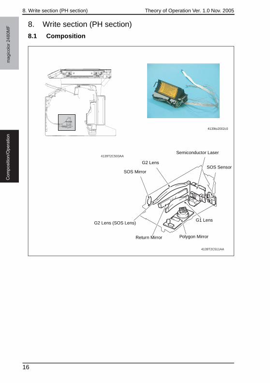
8. Write section (PH section)
8.1 Composition
4139to2002c0
4139T2C503AA
4139T2C511AA
SOS Mirror
G2 Lens
Semiconductor Laser
SOS Sensor
G1 Lens
Polygon MirrorReturn Mirror
G2 Lens (SOS Lens)
16
Theory of Operation Ver. 1.0 Nov. 2005 8. Write section (PH section)
ma
gic
olo
r 2
48
0M
FC
om
po
sitio
n/O
pe
ratio
n
8.2 Operation
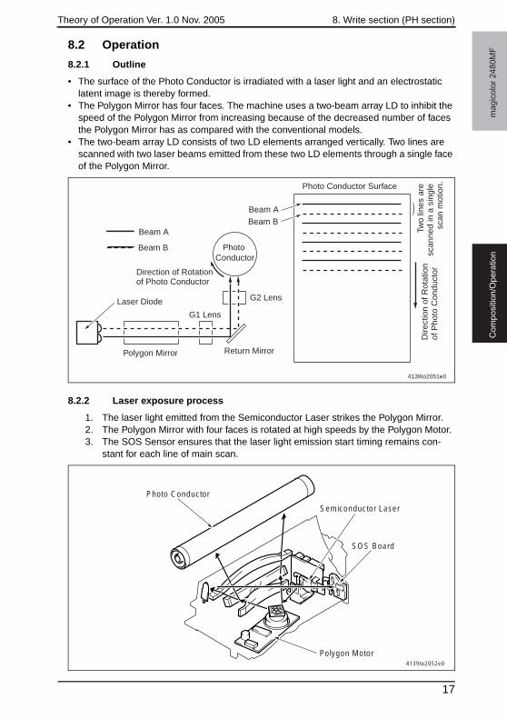
8.2.1 Outline
• The surface of the Photo Conductor is irradiated with a laser light and an electrostatic latent image is thereby formed.
• The Polygon Mirror has four faces. The machine uses a two-beam array LD to inhibit the speed of the Polygon Mirror from increasing because of the decreased number of faces the Polygon Mirror has as compared with the conventional models.
• The two-beam array LD consists of two LD elements arranged vertically. Two lines are scanned with two laser beams emitted from these two LD elements through a single face of the Polygon Mirror.
8.2.2 Laser exposure process
1. The laser light emitted from the Semiconductor Laser strikes the Polygon Mirror.2. The Polygon Mirror with four faces is rotated at high speeds by the Polygon Motor.3. The SOS Sensor ensures that the laser light emission start timing remains con-
stant for each line of main scan.
4139to2051e0
Photo Conductor
Polygon Mirror
Laser Diode
Beam A
Two
lines
are
sc
anne
d in
a s
ingl
e sc
an m
otio
n.Photo Conductor Surface
Dire
ctio
n of
Rot
atio
n of
Pho
to C
ondu
ctorDirection of Rotation
of Photo Conductor
Beam BBeam A
Beam B
Return Mirror
G2 Lens
G1 Lens
4139to2052e0
Photo Conductor
Semiconductor Laser
SOS Board
Polygon Motor
17
8. Write section (PH section) Theory of Operation Ver. 1.0 Nov. 2005m
ag
ico
lor
24
80
MF
Co
mp
ositio
n/O
pe
ratio
n
8.2.3 Laser emission timing
• When a Ready signal is detected after the lapse of a given period of time after the print cycle has been started, a Laser ON signal is output from the Print Control Board (PWB-P).
• The Laser ON signal triggers the firing of each laser light which illuminates the SOS Board via the Polygon Mirror, G1 Lens, Return Mirror, G2 Lens (SOS Lens), and SOS Mirror. This generates an SOS signal.
• This SOS (Start of Scan) signal unifies the timing at which the laser lights are irradiated for each main scan line.
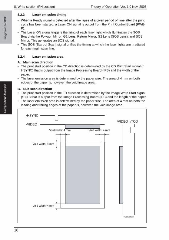
8.2.4 Laser emission area
A. Main scan direction • The print start position in the CD direction is determined by the CD Print Start signal (/
HSYNC) that is output from the Image Processing Board (IPB) and the width of the paper.
• The laser emission area is determined by the paper size. The area of 4 mm on both edges of the paper is, however, the void image area.
B. Sub scan direction • The print start position in the FD direction is determined by the Image Write Start signal
(/TOD) that is output from the Image Processing Board (IPB) and the length of the paper.• The laser emission area is determined by the paper size. The area of 4 mm on both the
leading and trailing edges of the paper is, however, the void image area.
4138to2595c0
Void width: 4 mm
Void width: 4 mm
Void width: 4 mm
Void width: 4 mm
18
Theory of Operation Ver. 1.0 Nov. 2005 9. Cartridge section
ma
gic
olo
r 2
48
0M
FC
om
po
sitio
n/O
pe
ratio
n
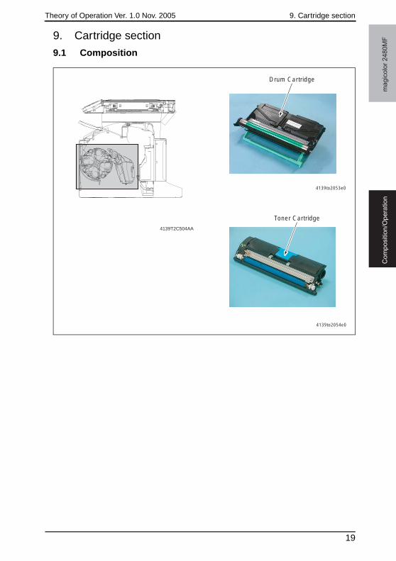
9. Cartridge section
9.1 Composition
4139T2C504AA
4139to2053e0
Drum Cartridge
4139to2054e0
Toner Cartridge
19
9. Cartridge section Theory of Operation Ver. 1.0 Nov. 2005m
ag
ico
lor
24
80
MF
Co
mp
ositio
n/O
pe
ratio
n
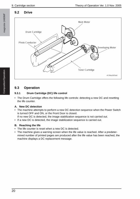
9.2 Drive
9.3 Operation
9.3.1 Drum Cartridge (DC) life control
• The Drum Cartridge offers the following life controls: detecting a new DC and resetting the life counter.
A. New DC detection• The machine attempts to perform a new DC detection sequence when the Power Switch
is turned OFF and ON, or the Front Door is closed.If no new DC is detected, the image stabilization sequence is not carried out.
• If a new DC is detected, the image stabilization sequence is carried out.
B. Reaching the life• The life counter is reset when a new DC is detected.• The machine gives a warning screen when the life value is reached. After a predeter-
mined number of printed pages are produced after the life value has been reached, the machine displays a DC replacement message.
4139to2055e0
Main Motor
Drum Cartridge
Photo Conductor
Toner Cartridge
Developing Motor
20
Theory of Operation Ver. 1.0 Nov. 2005 9. Cartridge section
ma
gic
olo
r 2
48
0M
FC
om
po
sitio
n/O
pe
ratio
n
9.3.2 Toner Cartridge (TC) life control
A. Toner Cartridge detection and new cartridge detection timing• The machine attempts to perform a detection sequence when the Front Door is closed.
B. Toner Cartridge detection• The machine accesses the TC Detection Board (CSIC) to check for data stored in it.
Using that data, the machine determines whether or not a Toner Cartridge is loaded.
C. New Toner Cartridge detection• After a Toner Cartridge has been detected, the machine determines whether it is new or
not based on the data acquired.
D. Toner Cartridge near empty and empty condition detection• The amount of toner consumed is calculated from the number of dots produced for one
printed page by the controller. A toner near empty condition and a toner empty condition are thereby detected.
<Toner near empty decision>1. The machine determines that there is a toner near empty condition when the image
counter and dot counter reach the life value.
<Toner empty decision>2. The machine determines that there is a toner empty condition when a predeter-
mined number of printed pages are produced after the toner near empty condition has been detected.
21
10. Photo Conductor section Theory of Operation Ver. 1.0 Nov. 2005m
ag
ico
lor
24
80
MF
Co
mp
ositio
n/O
pe
ratio
n
10. Photo Conductor section
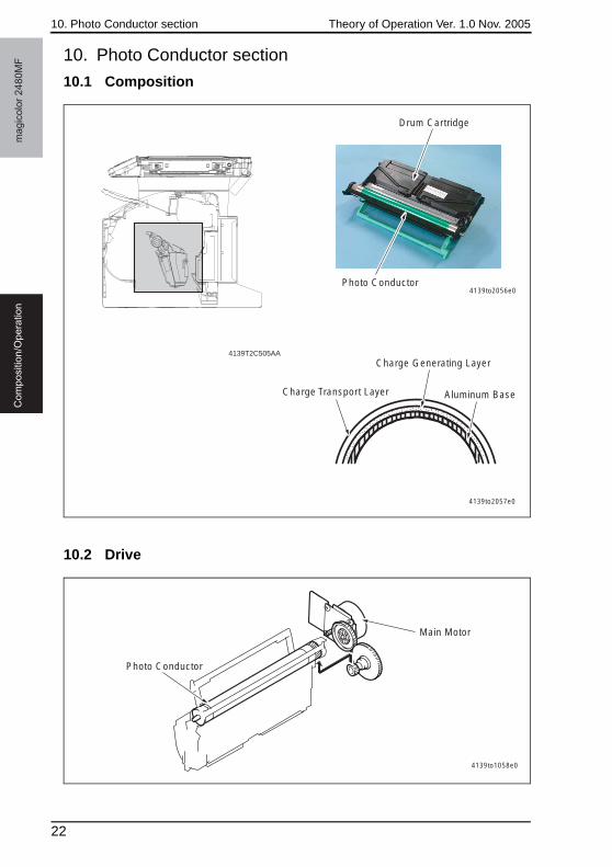
10.1 Composition
10.2 Drive
4139to2056e0
Drum Cartridge
Photo Conductor
Charge Generating Layer
Aluminum BaseCharge Transport Layer
4139to2057e0
4139T2C505AA
Main Motor
Photo Conductor
4139to1058e0
22
Theory of Operation Ver. 1.0 Nov. 2005 10. Photo Conductor section
ma
gic
olo
r 2
48
0M
FC
om
po
sitio
n/O
pe
ratio
n
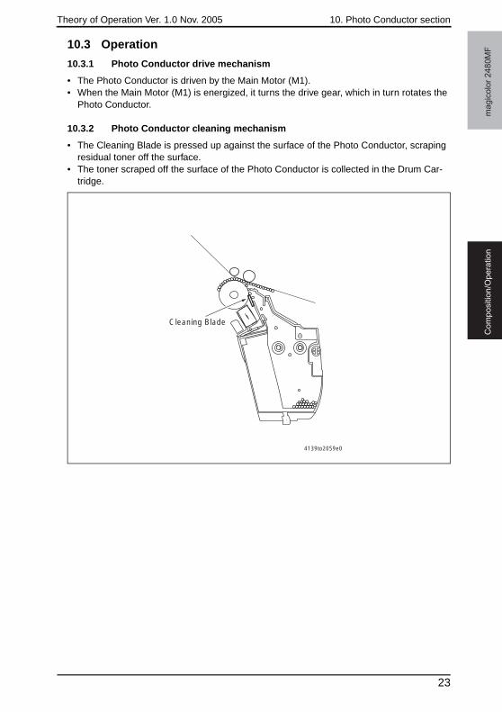
10.3 Operation
10.3.1 Photo Conductor drive mechanism
• The Photo Conductor is driven by the Main Motor (M1).• When the Main Motor (M1) is energized, it turns the drive gear, which in turn rotates the
Photo Conductor.
10.3.2 Photo Conductor cleaning mechanism
• The Cleaning Blade is pressed up against the surface of the Photo Conductor, scraping residual toner off the surface.
• The toner scraped off the surface of the Photo Conductor is collected in the Drum Car-tridge.
4139to2059e0
Cleaning Blade
23
11. Charge Corona section Theory of Operation Ver. 1.0 Nov. 2005m
ag
ico
lor
24
80
MF
Co
mp
ositio
n/O
pe
ratio
n
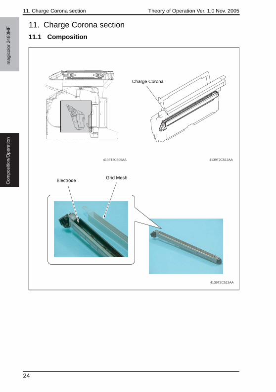
11. Charge Corona section
11.1 Composition
4139T2C513AA
4139T2C512AA4139T2C505AA
Charge Corona
ElectrodeGrid Mesh
24
Theory of Operation Ver. 1.0 Nov. 2005 11. Charge Corona section
ma
gic
olo
r 2
48
0M
FC
om
po
sitio
n/O
pe
ratio
n
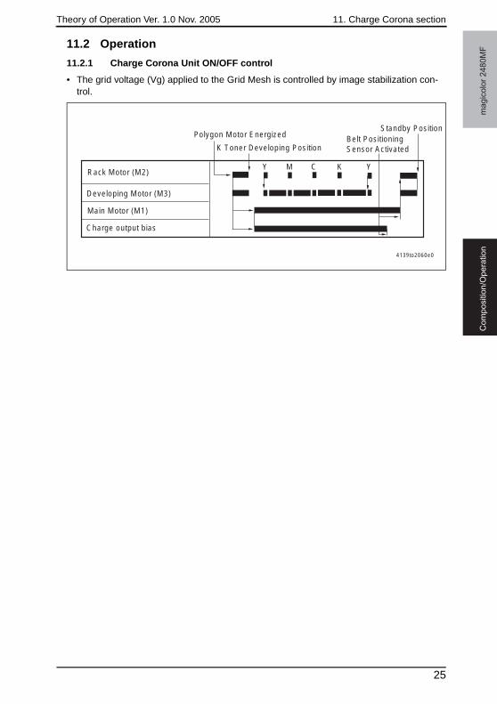
11.2 Operation
11.2.1 Charge Corona Unit ON/OFF control
• The grid voltage (Vg) applied to the Grid Mesh is controlled by image stabilization con-trol.
4139to2060e0
Y M C K Y
K Toner Developing Position
Standby PositionBelt Positioning Sensor Activated
Developing Motor (M3)
Charge output bias
Polygon Motor Energized
Rack Motor (M2)
Main Motor (M1)
25
12. Developing section Theory of Operation Ver. 1.0 Nov. 2005m
ag
ico
lor
24
80
MF
Co
mp
ositio
n/O
pe
ratio
n
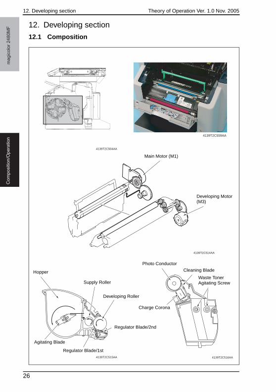
12. Developing section
12.1 Composition
4139T2C514AA
4139T2C515AA
4139T2C504AA
4139T2C516AA
4139T2C559AA
Main Motor (M1)
Developing Motor (M3)
Hopper
Supply Roller
Developing Roller
Regulator Blade/2nd
Regulator Blade/1st
Agitating Blade
Photo ConductorCleaning Blade
Waste Toner Agitating Screw
Charge Corona
26
Theory of Operation Ver. 1.0 Nov. 2005 12. Developing section
ma
gic
olo
r 2
48
0M
FC
om
po
sitio
n/O
pe
ratio
n
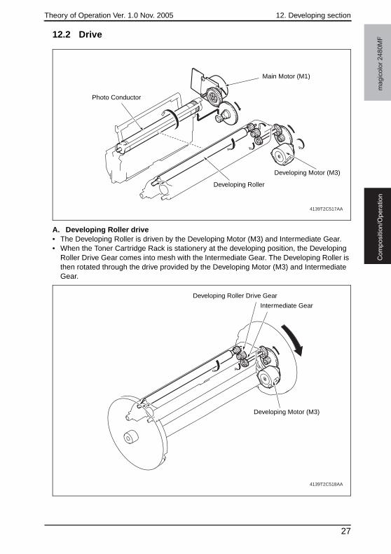
12.2 Drive
A. Developing Roller drive• The Developing Roller is driven by the Developing Motor (M3) and Intermediate Gear.• When the Toner Cartridge Rack is stationery at the developing position, the Developing
Roller Drive Gear comes into mesh with the Intermediate Gear. The Developing Roller is then rotated through the drive provided by the Developing Motor (M3) and Intermediate Gear.
4139T2C517AA
Photo Conductor
Main Motor (M1)
Developing Motor (M3)
Developing Roller
4139T2C518AA
Developing Roller Drive Gear
Intermediate Gear
Developing Motor (M3)
27
12. Developing section Theory of Operation Ver. 1.0 Nov. 2005m
ag
ico
lor
24
80
MF
Co
mp
ositio
n/O
pe
ratio
n
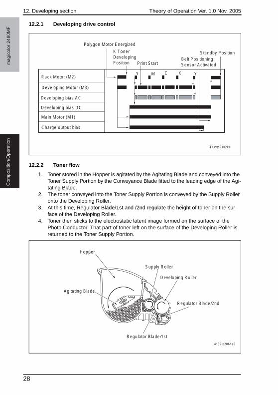
12.2.1 Developing drive control
12.2.2 Toner flow
1. Toner stored in the Hopper is agitated by the Agitating Blade and conveyed into the Toner Supply Portion by the Conveyance Blade fitted to the leading edge of the Agi-tating Blade.
2. The toner conveyed into the Toner Supply Portion is conveyed by the Supply Roller onto the Developing Roller.
3. At this time, Regulator Blade/1st and /2nd regulate the height of toner on the sur-face of the Developing Roller.
4. Toner then sticks to the electrostatic latent image formed on the surface of the Photo Conductor. That part of toner left on the surface of the Developing Roller is returned to the Toner Supply Portion.
Y M C K Y
K Toner Developing Position
Standby PositionBelt Positioning Sensor ActivatedPrint Start
Developing Motor (M3)
Charge output bias
Polygon Motor Energized
Rack Motor (M2)
Main Motor (M1)
Developing bias DC
Developing bias AC
4139to2102e0
4139to2061e0
Hopper
Supply Roller
Developing Roller
Regulator Blade/2nd
Regulator Blade/1st
Agitating Blade
28
Theory of Operation Ver. 1.0 Nov. 2005 12. Developing section
ma
gic
olo
r 2
48
0M
FC
om
po
sitio
n/O
pe
ratio
n
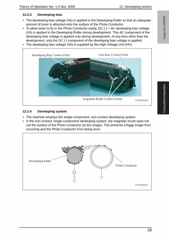
12.2.3 Developing bias
• The developing bias voltage (Vb) is applied to the Developing Roller so that an adequate amount of toner is attracted onto the surface of the Photo Conductor.
• To allow toner to fly to the Photo Conductor easily, DC (-) + AC developing bias voltage (Vb) is applied to the Developing Roller during development. This AC component of the developing bias voltage is applied only during development. At any time other than the development, only the DC (-) component of the developing bias voltage is applied.
• The developing bias voltage (Vb) is supplied by the High Voltage Unit (HV).
12.2.4 Developing system
• The machine employs the single-component, non-contact developing system.• In the non-contact, single-component developing system, the magnetic brush does not
rub the surface of the Photo Conductor (or the image). This prevents a foggy image from occurring and the Photo Conductor from being worn.
4139to2062e0
Developing Bias Contact Point
Regulator Blade Contact Points
Seal Bias Contact Point
4139to2063e1
Developing Roller
Photo Conductor
29
12. Developing section Theory of Operation Ver. 1.0 Nov. 2005m
ag
ico
lor
24
80
MF
Co
mp
ositio
n/O
pe
ratio
n
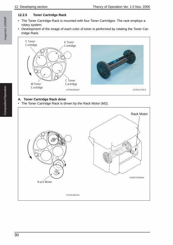
12.2.5 Toner Cartridge Rack
• The Toner Cartridge Rack is mounted with four Toner Cartridges. The rack employs a rotary system.
• Development of the image of each color of toner is performed by rotating the Toner Car-tridge Rack.
A. Toner Cartridge Rack drive• The Toner Cartridge Rack is driven by the Rack Motor (M2).
Y Toner Cartridge
K Toner Cartridge
C Toner CartridgeM Toner
Cartridge4139to2064e0 4139to1528c0
Rack Motor
4139to2065e0
4139T2C556AA
Rack Motor
30
Theory of Operation Ver. 1.0 Nov. 2005 12. Developing section
ma
gic
olo
r 2
48
0M
FC
om
po
sitio
n/O
pe
ratio
n
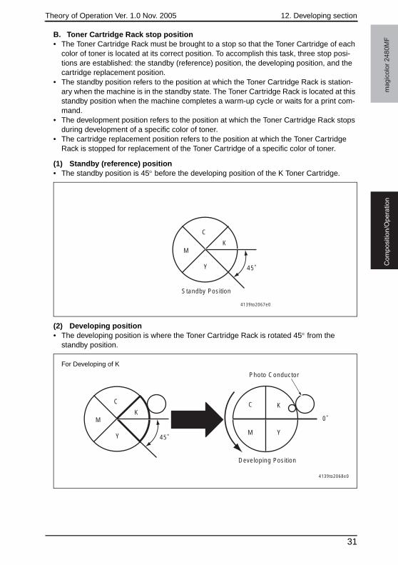
B. Toner Cartridge Rack stop position• The Toner Cartridge Rack must be brought to a stop so that the Toner Cartridge of each
color of toner is located at its correct position. To accomplish this task, three stop posi-tions are established: the standby (reference) position, the developing position, and the cartridge replacement position.
• The standby position refers to the position at which the Toner Cartridge Rack is station-ary when the machine is in the standby state. The Toner Cartridge Rack is located at this standby position when the machine completes a warm-up cycle or waits for a print com-mand.
• The development position refers to the position at which the Toner Cartridge Rack stops during development of a specific color of toner.
• The cartridge replacement position refers to the position at which the Toner Cartridge Rack is stopped for replacement of the Toner Cartridge of a specific color of toner.
(1) Standby (reference) position• The standby position is 45° before the developing position of the K Toner Cartridge.
(2) Developing position• The developing position is where the Toner Cartridge Rack is rotated 45° from the
standby position.
K
Y 45˚
Standby Position
C
M
4139to2067e0
K
Y
0˚
Developing Position
Photo Conductor
C
M
4139to2068e0
K
Y 45˚
C
M
For Developing of K
31
12. Developing section Theory of Operation Ver. 1.0 Nov. 2005m
ag
ico
lor
24
80
MF
Co
mp
ositio
n/O
pe
ratio
n
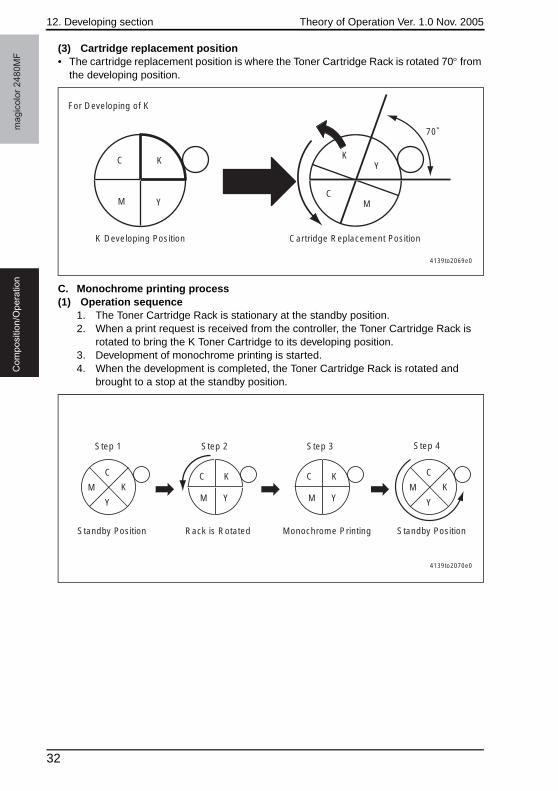
(3) Cartridge replacement position• The cartridge replacement position is where the Toner Cartridge Rack is rotated 70° from
the developing position.
C. Monochrome printing process(1) Operation sequence
1. The Toner Cartridge Rack is stationary at the standby position.2. When a print request is received from the controller, the Toner Cartridge Rack is
rotated to bring the K Toner Cartridge to its developing position.3. Development of monochrome printing is started.4. When the development is completed, the Toner Cartridge Rack is rotated and
brought to a stop at the standby position.
KY
70˚
Cartridge Replacement PositionK Developing Position
CM
4139to2069e0
K
Y
C
M
For Developing of K
KK K
Y Y
C C C
Step 1 Step 2 Step 3
Monochrome PrintingStandby Position Standby PositionRack is Rotated
Step 4
M K
Y
C
MM YM
4139to2070e0
32
Theory of Operation Ver. 1.0 Nov. 2005 12. Developing section
ma
gic
olo
r 2
48
0M
FC
om
po
sitio
n/O
pe
ratio
n
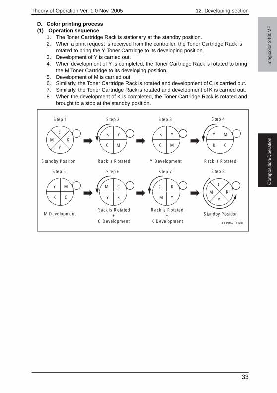
D. Color printing process(1) Operation sequence
1. The Toner Cartridge Rack is stationary at the standby position.2. When a print request is received from the controller, the Toner Cartridge Rack is
rotated to bring the Y Toner Cartridge to its developing position.3. Development of Y is carried out.4. When development of Y is completed, the Toner Cartridge Rack is rotated to bring
the M Toner Cartridge to its developing position.5. Development of M is carried out.6. Similarly, the Toner Cartridge Rack is rotated and development of C is carried out.7. Similarly, the Toner Cartridge Rack is rotated and development of K is carried out.8. When the development of K is completed, the Toner Cartridge Rack is rotated and
brought to a stop at the standby position.
KY Y
Y M
C K K
Step 1 Step 2 Step 3
Y DevelopmentStandby Position Rack is RotatedRack is Rotated
Step 4
MC MC
MY
Step 5
M Development
CK
MY
CK
C K
K
M C
Step 6 Step 7
Standby PositionRack is Rotated
+ C Development
Rack is Rotated +
K Development
Step 8
K
Y
C
MY YM
4139to2071e0
33
12. Developing section Theory of Operation Ver. 1.0 Nov. 2005m
ag
ico
lor
24
80
MF
Co
mp
ositio
n/O
pe
ratio
n
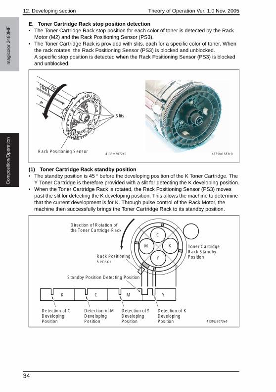
E. Toner Cartridge Rack stop position detection• The Toner Cartridge Rack stop position for each color of toner is detected by the Rack
Motor (M2) and the Rack Positioning Sensor (PS3).• The Toner Cartridge Rack is provided with slits, each for a specific color of toner. When
the rack rotates, the Rack Positioning Sensor (PS3) is blocked and unblocked.A specific stop position is detected when the Rack Positioning Sensor (PS3) is blocked and unblocked.
(1) Toner Cartridge Rack standby position• The standby position is 45 ° before the developing position of the K Toner Cartridge. The
Y Toner Cartridge is therefore provided with a slit for detecting the K developing position.• When the Toner Cartridge Rack is rotated, the Rack Positioning Sensor (PS3) moves
past the slit for detecting the K developing position. This allows the machine to determine that the current development is for K. Through pulse control of the Rack Motor, the machine then successfully brings the Toner Cartridge Rack to its standby position.
4139to2072e0Rack Positioning Sensor
Slits
4139to1583c0
4139to2073e0
YMCK
Y
M
C
K
Detection of K Developing Position
Detection of Y Developing Position
Detection of M Developing Position
Detection of C Developing Position
Standby Position Detecting Position
Rack Positioning Sensor
Direction of Rotation of the Toner Cartridge Rack
Toner Cartridge Rack Standby Position
34

Theory of Operation Ver. 1.0 Nov. 2005 12. Developing section
ma
gic
olo
r 2
48
0M
FC
om
po
sitio
n/O
pe
ratio
n
(2) Toner Cartridge Rack developing position• To bring the Toner Cartridge Rack to a stop at the corresponding developing position, the
rack is rotated from the standby position 45° through pulse control of the Rack Motor.
(3) Cartridge replacement position• When a request is made for replacing the Toner Cartridge of a specific color of toner (by
means of an input from the control panel, upon a toner empty condition, or through an input made via the printer driver), the Toner Cartridge Rack is rotated 70° from the devel-oping position through pulse control of the Rack Motor.
35
13. Image Transfer Section Theory of Operation Ver. 1.0 Nov. 2005m
ag
ico
lor
24
80
MF
Co
mp
ositio
n/O
pe
ratio
n
13. Image Transfer Section
13.1 Composition
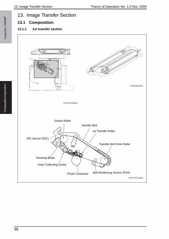
13.1.1 1st transfer section
4139T2C519AA
4139to2019c0
4139T2C506AA
Driven Roller
Transfer Belt
1st Transfer Roller
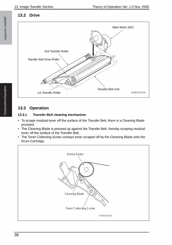
Transfer Belt Drive Roller
Belt Positioning Sensor (PS4)Photo Conductor
Toner Collecting Screw
Cleaning Blade
IDC Sensor (IDC)
36
Theory of Operation Ver. 1.0 Nov. 2005 13. Image Transfer Section
ma
gic
olo
r 2
48
0M
FC
om
po
sitio
n/O
pe
ratio
n
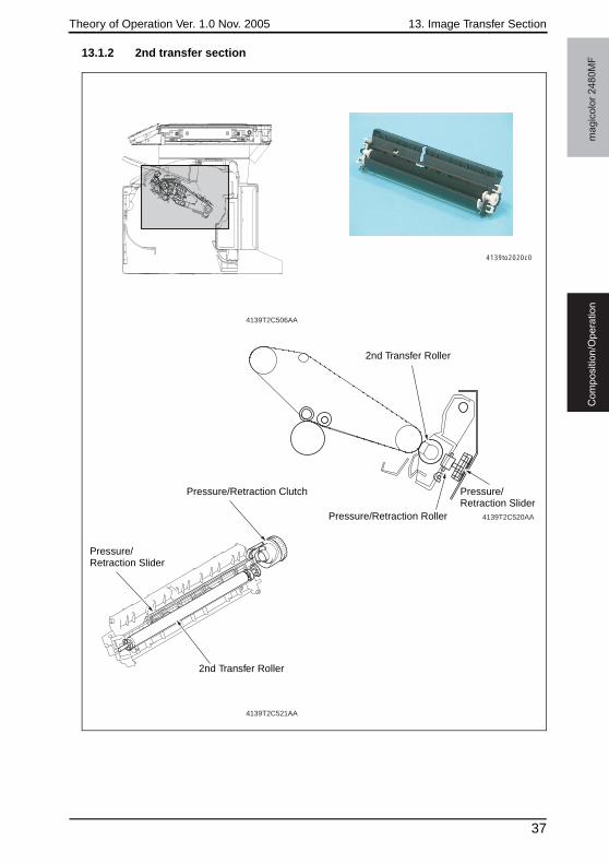
13.1.2 2nd transfer section
4139T2C506AA
4139T2C520AA
4139to2020c0
4139T2C521AA
2nd Transfer Roller
Pressure/Retraction Slider
Pressure/Retraction Roller
Pressure/Retraction Clutch
Pressure/Retraction Slider
2nd Transfer Roller
37
13. Image Transfer Section Theory of Operation Ver. 1.0 Nov. 2005m
ag
ico
lor
24
80
MF
Co
mp
ositio
n/O
pe
ratio
n
13.2 Drive
13.3 Operation
13.3.1 Transfer Belt cleaning mechanism
• To scrape residual toner off the surface of the Transfer Belt, there is a Cleaning Blade provided.
• The Cleaning Blade is pressed up against the Transfer Belt, thereby scraping residual toner off the surface of the Transfer Belt.
• The Toner Collecting Screw conveys toner scraped off by the Cleaning Blade onto the Drum Cartridge.
4139T2C522AA
Main Motor (M1)
Transfer Belt Unit1st Transfer Roller
Transfer Belt Drive Roller
2nd Transfer Roller
Driven Roller
Cleaning Blade
Toner Collecting Screw
4139to2074e0
38
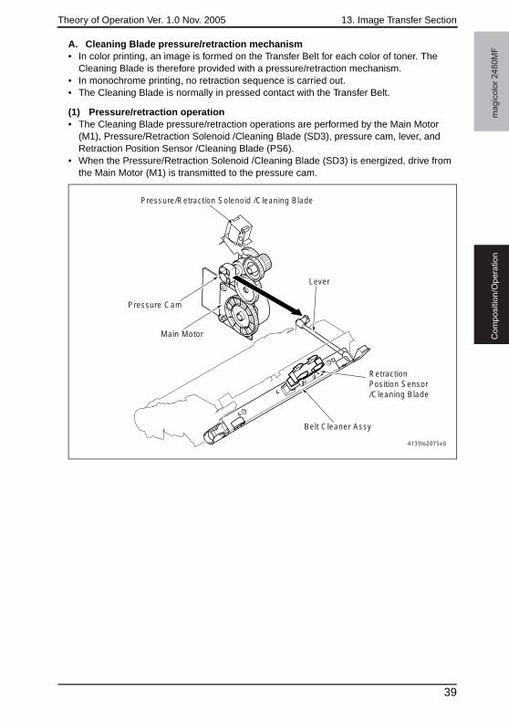
Theory of Operation Ver. 1.0 Nov. 2005 13. Image Transfer Section
ma
gic
olo
r 2
48
0M
FC
om
po
sitio
n/O
pe
ratio
n
A. Cleaning Blade pressure/retraction mechanism• In color printing, an image is formed on the Transfer Belt for each color of toner. The
Cleaning Blade is therefore provided with a pressure/retraction mechanism.• In monochrome printing, no retraction sequence is carried out.• The Cleaning Blade is normally in pressed contact with the Transfer Belt.
(1) Pressure/retraction operation• The Cleaning Blade pressure/retraction operations are performed by the Main Motor
(M1), Pressure/Retraction Solenoid /Cleaning Blade (SD3), pressure cam, lever, and Retraction Position Sensor /Cleaning Blade (PS6).
• When the Pressure/Retraction Solenoid /Cleaning Blade (SD3) is energized, drive from the Main Motor (M1) is transmitted to the pressure cam.
Pressure Cam
Pressure/Retraction Solenoid /Cleaning Blade
Main Motor
Belt Cleaner Assy
Retraction Position Sensor /Cleaning Blade
Lever
4139to2075e0
39
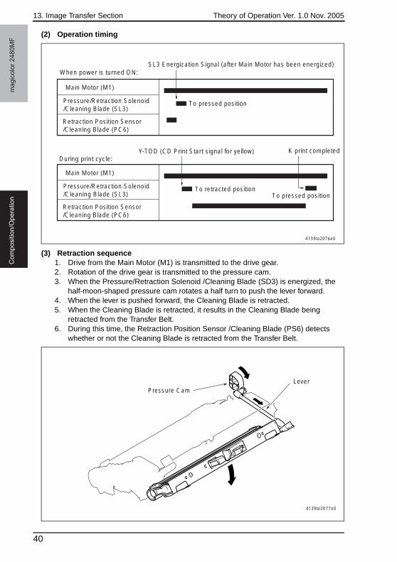
13. Image Transfer Section Theory of Operation Ver. 1.0 Nov. 2005m
ag
ico
lor
24
80
MF
Co
mp
ositio
n/O
pe
ratio
n
(2) Operation timing
(3) Retraction sequence1. Drive from the Main Motor (M1) is transmitted to the drive gear.2. Rotation of the drive gear is transmitted to the pressure cam.3. When the Pressure/Retraction Solenoid /Cleaning Blade (SD3) is energized, the
half-moon-shaped pressure cam rotates a half turn to push the lever forward.4. When the lever is pushed forward, the Cleaning Blade is retracted.5. When the Cleaning Blade is retracted, it results in the Cleaning Blade being
retracted from the Transfer Belt.6. During this time, the Retraction Position Sensor /Cleaning Blade (PS6) detects
whether or not the Cleaning Blade is retracted from the Transfer Belt.
Pressure/Retraction Solenoid/Cleaning Blade (SL3)
Main Motor (M1)
Retraction Position Sensor /Cleaning Blade (PC6)
SL3 Energization Signal (after Main Motor has been energized)
Pressure/Retraction Solenoid /Cleaning Blade (SL3)
Main Motor (M1)
Retraction Position Sensor /Cleaning Blade (PC6)
When power is turned ON:
To pressed position
During print cycle:Y-TOD (CD Print Start signal for yellow)
To retracted position
K print completed
To pressed position
4139to2076e0
Pressure CamLever
4139to2077e0
40
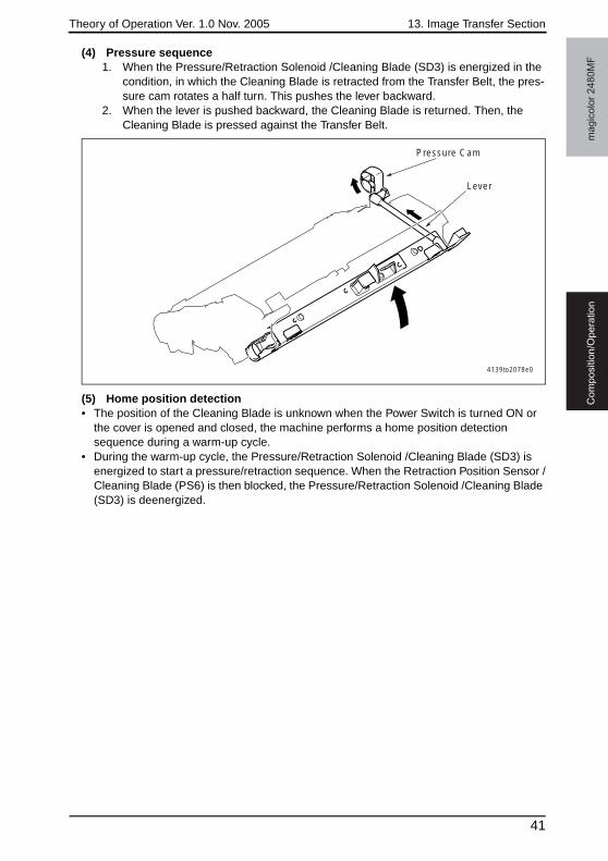
Theory of Operation Ver. 1.0 Nov. 2005 13. Image Transfer Section
ma
gic
olo
r 2
48
0M
FC
om
po
sitio
n/O
pe
ratio
n
(4) Pressure sequence1. When the Pressure/Retraction Solenoid /Cleaning Blade (SD3) is energized in the
condition, in which the Cleaning Blade is retracted from the Transfer Belt, the pres-sure cam rotates a half turn. This pushes the lever backward.
2. When the lever is pushed backward, the Cleaning Blade is returned. Then, the Cleaning Blade is pressed against the Transfer Belt.
(5) Home position detection• The position of the Cleaning Blade is unknown when the Power Switch is turned ON or
the cover is opened and closed, the machine performs a home position detection sequence during a warm-up cycle.
• During the warm-up cycle, the Pressure/Retraction Solenoid /Cleaning Blade (SD3) is energized to start a pressure/retraction sequence. When the Retraction Position Sensor /Cleaning Blade (PS6) is then blocked, the Pressure/Retraction Solenoid /Cleaning Blade (SD3) is deenergized.
Pressure Cam
Lever
4139to2078e0
41
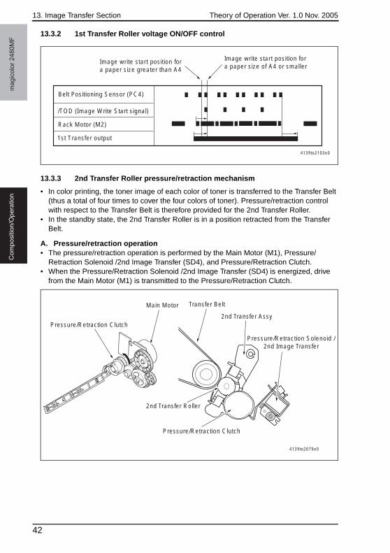
13. Image Transfer Section Theory of Operation Ver. 1.0 Nov. 2005m
ag
ico
lor
24
80
MF
Co
mp
ositio
n/O
pe
ratio
n
13.3.2 1st Transfer Roller voltage ON/OFF control
13.3.3 2nd Transfer Roller pressure/retraction mechanism
• In color printing, the toner image of each color of toner is transferred to the Transfer Belt (thus a total of four times to cover the four colors of toner). Pressure/retraction control with respect to the Transfer Belt is therefore provided for the 2nd Transfer Roller.
• In the standby state, the 2nd Transfer Roller is in a position retracted from the Transfer Belt.
A. Pressure/retraction operation• The pressure/retraction operation is performed by the Main Motor (M1), Pressure/
Retraction Solenoid /2nd Image Transfer (SD4), and Pressure/Retraction Clutch.• When the Pressure/Retraction Solenoid /2nd Image Transfer (SD4) is energized, drive
from the Main Motor (M1) is transmitted to the Pressure/Retraction Clutch.
4139to2103e0
/TOD (Image Write Start signal)
1st Transfer output
Belt Positioning Sensor (PC4)
Image write start position for a paper size of A4 or smaller
Image write start position for a paper size greater than A4
Rack Motor (M2)
4139to2079e0
Pressure/Retraction Clutch
Main Motor
2nd Transfer Roller
Pressure/Retraction Clutch
Transfer Belt
2nd Transfer Assy
Pressure/Retraction Solenoid /2nd Image Transfer
42
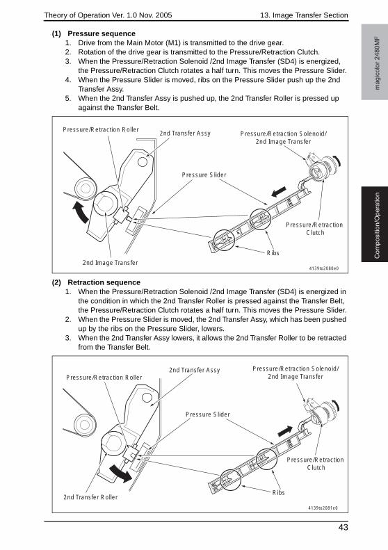
Theory of Operation Ver. 1.0 Nov. 2005 13. Image Transfer Section
ma
gic
olo
r 2
48
0M
FC
om
po
sitio
n/O
pe
ratio
n
(1) Pressure sequence1. Drive from the Main Motor (M1) is transmitted to the drive gear.2. Rotation of the drive gear is transmitted to the Pressure/Retraction Clutch.3. When the Pressure/Retraction Solenoid /2nd Image Transfer (SD4) is energized,
the Pressure/Retraction Clutch rotates a half turn. This moves the Pressure Slider.4. When the Pressure Slider is moved, ribs on the Pressure Slider push up the 2nd
Transfer Assy.5. When the 2nd Transfer Assy is pushed up, the 2nd Transfer Roller is pressed up
against the Transfer Belt.
(2) Retraction sequence1. When the Pressure/Retraction Solenoid /2nd Image Transfer (SD4) is energized in
the condition in which the 2nd Transfer Roller is pressed against the Transfer Belt, the Pressure/Retraction Clutch rotates a half turn. This moves the Pressure Slider.
2. When the Pressure Slider is moved, the 2nd Transfer Assy, which has been pushed up by the ribs on the Pressure Slider, lowers.
3. When the 2nd Transfer Assy lowers, it allows the 2nd Transfer Roller to be retracted from the Transfer Belt.
Ribs
Pressure Slider
Pressure/Retraction Solenoid/2nd Image Transfer
Pressure/Retraction Clutch
2nd Transfer AssyPressure/Retraction Roller
2nd Image Transfer4139to2080e0
Ribs
Pressure/Retraction Solenoid/2nd Image Transfer
Pressure/Retraction Clutch
Pressure Slider
2nd Transfer Roller
2nd Transfer AssyPressure/Retraction Roller
4139to2081e0
43
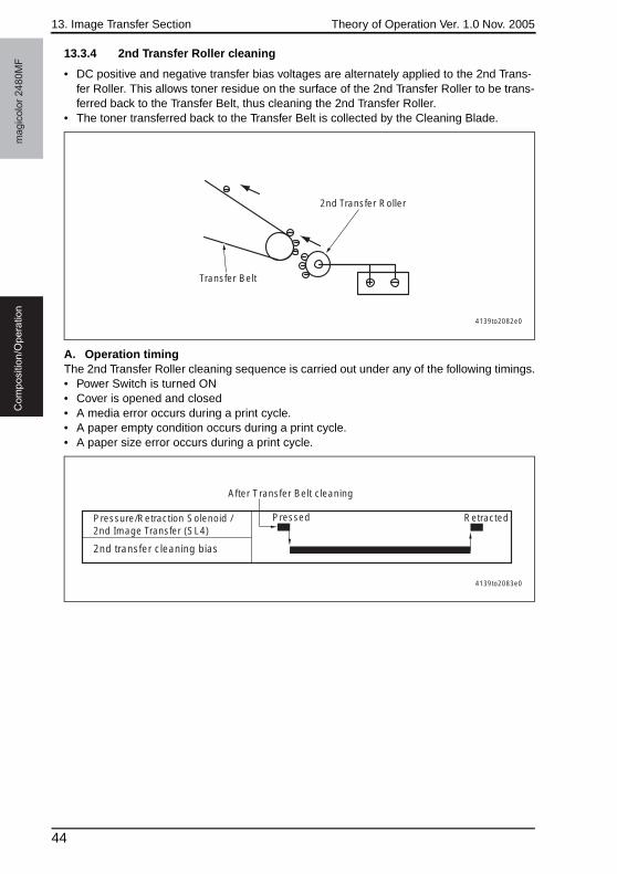
13. Image Transfer Section Theory of Operation Ver. 1.0 Nov. 2005m
ag
ico
lor
24
80
MF
Co
mp
ositio
n/O
pe
ratio
n
13.3.4 2nd Transfer Roller cleaning
• DC positive and negative transfer bias voltages are alternately applied to the 2nd Trans-fer Roller. This allows toner residue on the surface of the 2nd Transfer Roller to be trans-ferred back to the Transfer Belt, thus cleaning the 2nd Transfer Roller.
• The toner transferred back to the Transfer Belt is collected by the Cleaning Blade.
A. Operation timingThe 2nd Transfer Roller cleaning sequence is carried out under any of the following timings.• Power Switch is turned ON• Cover is opened and closed• A media error occurs during a print cycle.• A paper empty condition occurs during a print cycle.• A paper size error occurs during a print cycle.
Transfer Belt
2nd Transfer Roller
4139to2082e0
Pressure/Retraction Solenoid /2nd Image Transfer (SL4)
2nd transfer cleaning bias
Pressed Retracted
After Transfer Belt cleaning
4139to2083e0
44
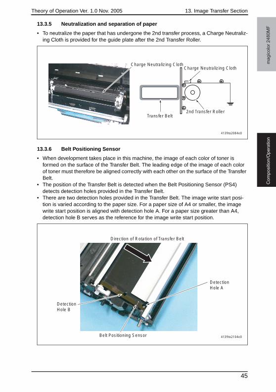
Theory of Operation Ver. 1.0 Nov. 2005 13. Image Transfer Section
ma
gic
olo
r 2
48
0M
FC
om
po
sitio
n/O
pe
ratio
n
13.3.5 Neutralization and separation of paper
• To neutralize the paper that has undergone the 2nd transfer process, a Charge Neutraliz-ing Cloth is provided for the guide plate after the 2nd Transfer Roller.
13.3.6 Belt Positioning Sensor
• When development takes place in this machine, the image of each color of toner is formed on the surface of the Transfer Belt. The leading edge of the image of each color of toner must therefore be aligned correctly with each other on the surface of the Transfer Belt.
• The position of the Transfer Belt is detected when the Belt Positioning Sensor (PS4) detects detection holes provided in the Transfer Belt.
• There are two detection holes provided in the Transfer Belt. The image write start posi-tion is varied according to the paper size. For a paper size of A4 or smaller, the image write start position is aligned with detection hole A. For a paper size greater than A4, detection hole B serves as the reference for the image write start position.
4139to2084e0
Transfer Belt 2nd Transfer Roller
Charge Neutralizing ClothCharge Neutralizing Cloth
4139to2104e0
Detection Hole A
Direction of Rotation of Transfer Belt
Detection Hole B
Belt Positioning Sensor
45
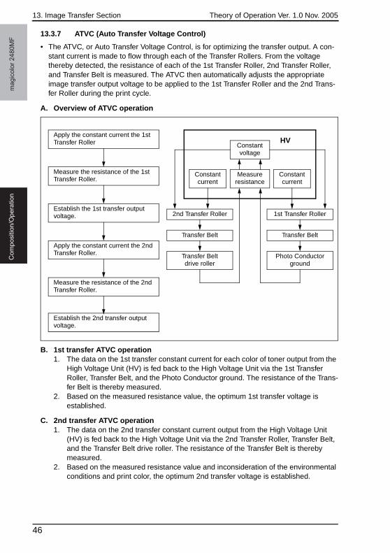
13. Image Transfer Section Theory of Operation Ver. 1.0 Nov. 2005m
ag
ico
lor
24
80
MF
Co
mp
ositio
n/O
pe
ratio
n
13.3.7 ATVC (Auto Transfer Voltage Control)
• The ATVC, or Auto Transfer Voltage Control, is for optimizing the transfer output. A con-stant current is made to flow through each of the Transfer Rollers. From the voltage thereby detected, the resistance of each of the 1st Transfer Roller, 2nd Transfer Roller, and Transfer Belt is measured. The ATVC then automatically adjusts the appropriate image transfer output voltage to be applied to the 1st Transfer Roller and the 2nd Trans-fer Roller during the print cycle.
A. Overview of ATVC operation
B. 1st transfer ATVC operation1. The data on the 1st transfer constant current for each color of toner output from the
High Voltage Unit (HV) is fed back to the High Voltage Unit via the 1st Transfer Roller, Transfer Belt, and the Photo Conductor ground. The resistance of the Trans-fer Belt is thereby measured.
2. Based on the measured resistance value, the optimum 1st transfer voltage is established.
C. 2nd transfer ATVC operation1. The data on the 2nd transfer constant current output from the High Voltage Unit
(HV) is fed back to the High Voltage Unit via the 2nd Transfer Roller, Transfer Belt, and the Transfer Belt drive roller. The resistance of the Transfer Belt is thereby measured.
2. Based on the measured resistance value and inconsideration of the environmental conditions and print color, the optimum 2nd transfer voltage is established.
Measure resistance
Constant current
Constant current
Constant voltage
2nd Transfer Roller
Transfer Belt
Transfer Belt drive roller
1st Transfer Roller
Transfer Belt
Photo Conductor ground
HVApply the constant current the 1st Transfer Roller
Measure the resistance of the 1st Transfer Roller.
Establish the 1st transfer output voltage.
Apply the constant current the 2nd Transfer Roller.
Measure the resistance of the 2nd Transfer Roller.
Establish the 2nd transfer output voltage.
46
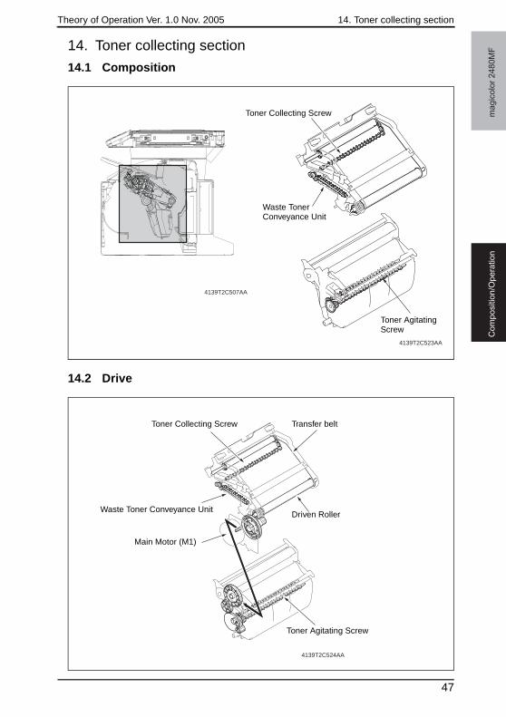
Theory of Operation Ver. 1.0 Nov. 2005 14. Toner collecting section
ma
gic
olo
r 2
48
0M
FC
om
po
sitio
n/O
pe
ratio
n
14. Toner collecting section
14.1 Composition
14.2 Drive
4139T2C507AA
4139T2C523AA
Toner Collecting Screw
Waste Toner Conveyance Unit
Toner Agitating Screw
4139T2C524AA
Toner Collecting Screw Transfer belt
Driven Roller
Toner Agitating Screw
Main Motor (M1)
Waste Toner Conveyance Unit
47
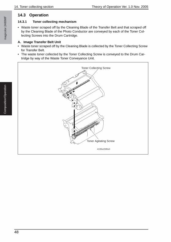
14. Toner collecting section Theory of Operation Ver. 1.0 Nov. 2005m
ag
ico
lor
24
80
MF
Co
mp
ositio
n/O
pe
ratio
n
14.3 Operation
14.3.1 Toner collecting mechanism
• Waste toner scraped off by the Cleaning Blade of the Transfer Belt and that scraped off by the Cleaning Blade of the Photo Conductor are conveyed by each of the Toner Col-lecting Screws into the Drum Cartridge.
A. Image Transfer Belt Unit• Waste toner scraped off by the Cleaning Blade is collected by the Toner Collecting Screw
for Transfer Belt.• The waste toner collected by the Toner Collecting Screw is conveyed to the Drum Car-
tridge by way of the Waste Toner Conveyance Unit.
4139to2085e0
Toner Collecting Screw
Toner Agitating Screw
48
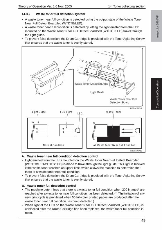
Theory of Operation Ver. 1.0 Nov. 2005 14. Toner collecting section
ma
gic
olo
r 2
48
0M
FC
om
po
sitio
n/O
pe
ratio
n
14.3.2 Waste toner full detection system
• A waste toner near full condition is detected using the output state of the Waste Toner Near Full Detect Board/led (WTDTB/LED).
• A waste toner near full condition is detected by letting the light emitted from the LED mounted on the Waste Toner Near Full Detect Board/led (WTDTB/LED) travel through the light guide.
• To prevent false detection, the Drum Cartridge is provided with the Toner Agitating Screw that ensures that the waste toner is evenly stored.
A. Waste toner near full condition detection control• Light emitted from the LED mounted on the Waste Toner Near Full Detect Board/led
(WTDTB/LEDWTDTB/LED) is made to travel through the light guide. This light is blocked if the waste toner reaches an upper limit, which allows the machine to determine that there is a waste toner near full condition.
• To prevent false detection, the Drum Cartridge is provided with the Toner Agitating Screw that ensures that the waste toner is evenly stored.
B. Waste toner full detection control• The machine determines that there is a waste toner full condition when 200 images* are
reached after a waste toner near full condition has been detected. (*: The initiation of any new print cycle is prohibited when 50 full-color printed pages are produced after the waste toner near full condition has been detected.)
• When light of the LED on the Waste Toner Near Full Detect Board/led (WTDTB/LED) is unblocked after the Drum Cartridge has been replaced, the waste toner full condition is reset.
Normal Condition
LED Waste TonerLED LightLight Guide
At Waste Toner Near Full Condition
4139to2087e0
Waste Toner Near Full Detection Board
Light Guide
Waste Toner Detection Area
4139to2086e1
49
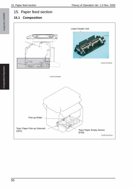
15. Paper feed section Theory of Operation Ver. 1.0 Nov. 2005m
ag
ico
lor
24
80
MF
Co
mp
ositio
n/O
pe
ratio
n
15. Paper feed section
15.1 Composition
4139T2C551AA
4139T2C508AA
4139T2C525AA
Lower Feeder Unit
Tray1 Paper Empty Sensor (PS9)
Tray1 Paper Pick-up Solenoid (SD1)
Pick-up Roller
50
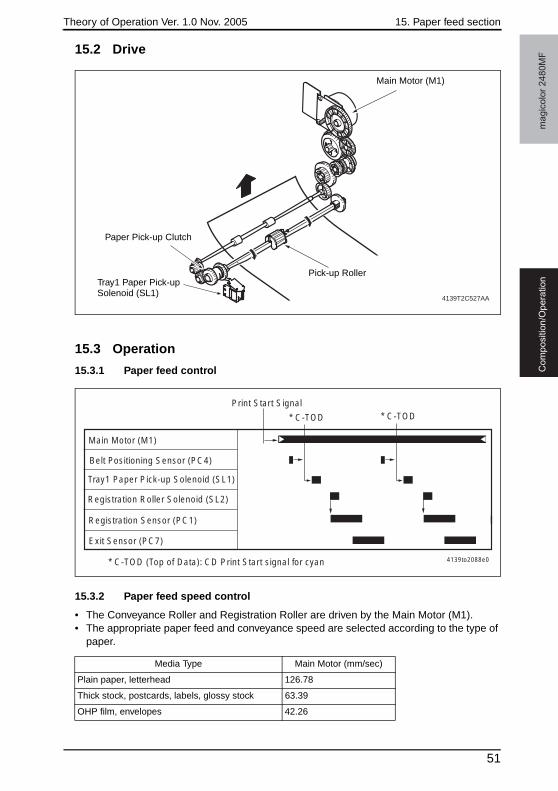
Theory of Operation Ver. 1.0 Nov. 2005 15. Paper feed section
ma
gic
olo
r 2
48
0M
FC
om
po
sitio
n/O
pe
ratio
n
15.2 Drive
15.3 Operation
15.3.1 Paper feed control
15.3.2 Paper feed speed control
• The Conveyance Roller and Registration Roller are driven by the Main Motor (M1).• The appropriate paper feed and conveyance speed are selected according to the type of
paper.
4139T2C527AA
Main Motor (M1)
Pick-up RollerTray1 Paper Pick-up Solenoid (SL1)
Paper Pick-up Clutch
Main Motor (M1)
* C-TOD
Tray1 Paper Pick-up Solenoid (SL1)
Registration Roller Solenoid (SL2)
Print Start Signal
Registration Sensor (PC1)
Belt Positioning Sensor (PC4)
* C-TOD
* C-TOD (Top of Data): CD Print Start signal for cyan
Exit Sensor (PC7)
4139to2088e0
Media Type Main Motor (mm/sec)
Plain paper, letterhead 126.78
Thick stock, postcards, labels, glossy stock 63.39
OHP film, envelopes 42.26
51
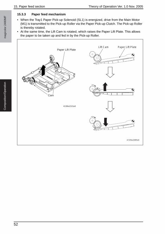
15. Paper feed section Theory of Operation Ver. 1.0 Nov. 2005m
ag
ico
lor
24
80
MF
Co
mp
ositio
n/O
pe
ratio
n
15.3.3 Paper feed mechanism
• When the Tray1 Paper Pick-up Solenoid (SL1) is energized, drive from the Main Motor (M1) is transmitted to the Pick-up Roller via the Paper Pick-up Clutch. The Pick-up Roller is thereby rotated.
• At the same time, the Lift Cam is rotated, which raises the Paper Lift Plate. This allows the paper to be taken up and fed in by the Pick-up Roller.
4139to2089e0
Lift Cam Paper Lift Plate
Cam
Paper Lift Plate
4139to2101e0
52
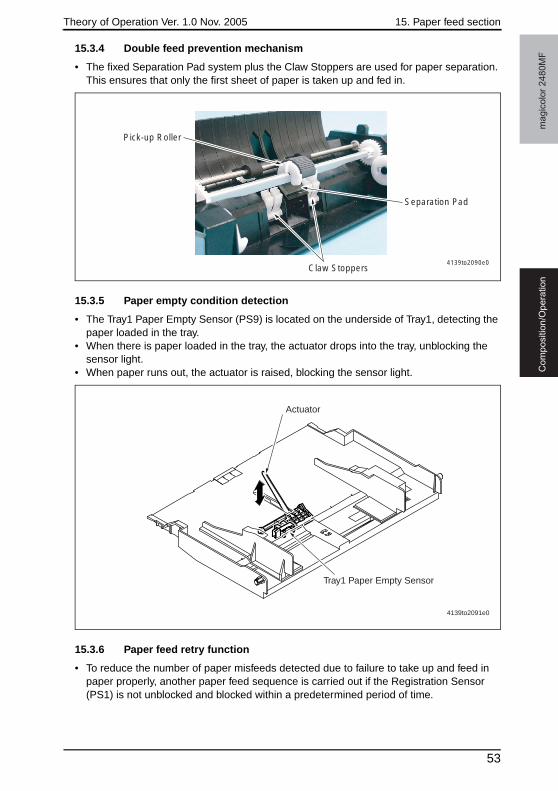
Theory of Operation Ver. 1.0 Nov. 2005 15. Paper feed section
ma
gic
olo
r 2
48
0M
FC
om
po
sitio
n/O
pe
ratio
n
15.3.4 Double feed prevention mechanism
• The fixed Separation Pad system plus the Claw Stoppers are used for paper separation. This ensures that only the first sheet of paper is taken up and fed in.
15.3.5 Paper empty condition detection
• The Tray1 Paper Empty Sensor (PS9) is located on the underside of Tray1, detecting the paper loaded in the tray.
• When there is paper loaded in the tray, the actuator drops into the tray, unblocking the sensor light.
• When paper runs out, the actuator is raised, blocking the sensor light.
15.3.6 Paper feed retry function
• To reduce the number of paper misfeeds detected due to failure to take up and feed in paper properly, another paper feed sequence is carried out if the Registration Sensor (PS1) is not unblocked and blocked within a predetermined period of time.
4139to2090e0
Separation Pad
Claw Stoppers
Pick-up Roller
Tray1 Paper Empty Sensor
Actuator
4139to2091e0
53
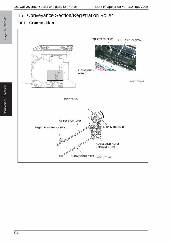
16. Conveyance Section/Registration Roller Theory of Operation Ver. 1.0 Nov. 2005m
ag
ico
lor
24
80
MF
Co
mp
ositio
n/O
pe
ratio
n
16. Conveyance Section/Registration Roller
16.1 Composition
4139T2C509AA
4139T2C529AA
4139T2C528AA
Registration roller OHP Sensor (PS2)
Conveyance roller
Registration Sensor (PS1) Main Motor (M1)
Registration Roller Solenoid (SD2)
Registration roller
Conveyance roller
54
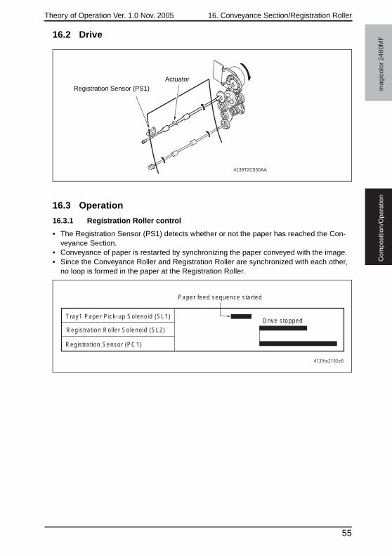
Theory of Operation Ver. 1.0 Nov. 2005 16. Conveyance Section/Registration Roller
ma
gic
olo
r 2
48
0M
FC
om
po
sitio
n/O
pe
ratio
n
16.2 Drive
16.3 Operation
16.3.1 Registration Roller control
• The Registration Sensor (PS1) detects whether or not the paper has reached the Con-veyance Section.
• Conveyance of paper is restarted by synchronizing the paper conveyed with the image.• Since the Conveyance Roller and Registration Roller are synchronized with each other,
no loop is formed in the paper at the Registration Roller.
4139T2C530AA
Registration Sensor (PS1)Actuator
4139to2105e0
Tray1 Paper Pick-up Solenoid (SL1)
Paper feed sequence started
Drive stopped
Registration Sensor (PC1)
Registration Roller Solenoid (SL2)
55
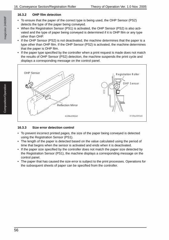
16. Conveyance Section/Registration Roller Theory of Operation Ver. 1.0 Nov. 2005m
ag
ico
lor
24
80
MF
Co
mp
ositio
n/O
pe
ratio
n
16.3.2 OHP film detection
• To ensure that the paper of the correct type is being used, the OHP Sensor (PS2) detects the type of the paper being conveyed.
• When the Registration Sensor (PS1) is activated, the OHP Sensor (PS2) is also acti-vated and the type of paper being conveyed is determined if it is OHP film or any type other than OHP.
• If the OHP Sensor (PS2) is not deactivated, the machine determines that the paper is a type other than OHP film. If the OHP Sensor (PS2) is activated, the machine determines that the paper is OHP film.
• If the paper type specified by the controller when a print request is made does not match the results of OHP Sensor (PS2) detection, the machine suspends the print cycle and displays a corresponding message on the control panel.
16.3.3 Size error detection control
• To prevent incorrect printed pages, the size of the paper being conveyed is detected using the Registration Sensor (PS1).
• The length of the paper is detected based on the value calculated using the period of time that begins when the sensor is activated and ends when it is deactivated.
• If the paper size specified by the controller does not match the paper size detected by the Registration Sensor (PS1), the machine displays a corresponding message on the control panel.
• The paper that has caused the size error is subject to the print processes. Operations for the subsequent sheets of paper can be specified from the controller.
4139to2092e0
OHP Sensor
Reflection Mirror
Registration Roller
OHP Sensor
4139to2093e0
56
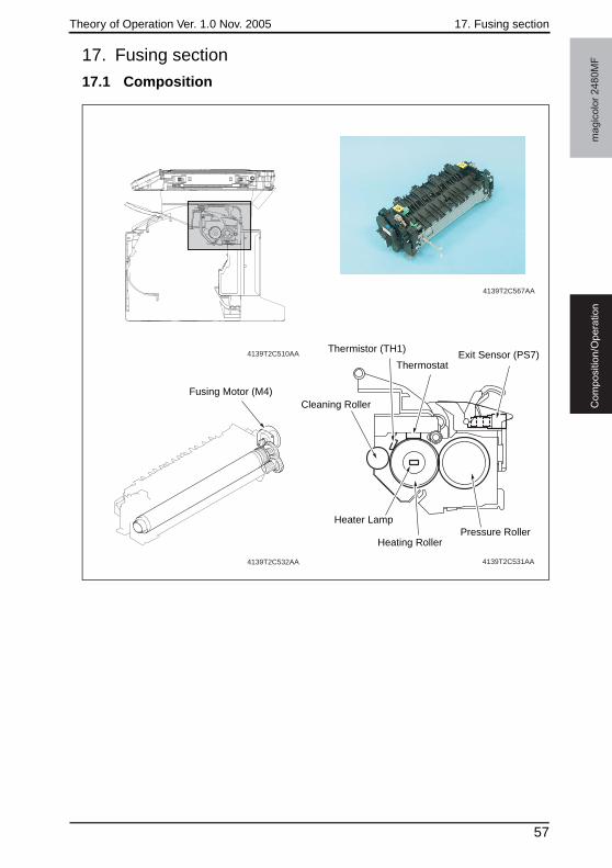
Theory of Operation Ver. 1.0 Nov. 2005 17. Fusing section
ma
gic
olo
r 2
48
0M
FC
om
po
sitio
n/O
pe
ratio
n
17. Fusing section
17.1 Composition
4139T2C510AA
4139T2C567AA
4139T2C531AA4139T2C532AA
Thermistor (TH1)
ThermostatExit Sensor (PS7)
Pressure RollerHeating Roller
Heater Lamp
Cleaning RollerFusing Motor (M4)
57
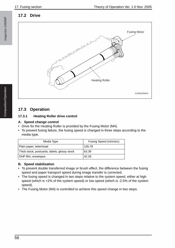
17. Fusing section Theory of Operation Ver. 1.0 Nov. 2005m
ag
ico
lor
24
80
MF
Co
mp
ositio
n/O
pe
ratio
n
17.2 Drive
17.3 Operation
17.3.1 Heating Roller drive control
A. Speed change control• Drive for the Heating Roller is provided by the Fusing Motor (M4).• To prevent fusing failure, the fusing speed is changed in three steps according to the
media type.
B. Speed stabilization• To prevent double transferred image or brush effect, the difference between the fusing
speed and paper transport speed during image transfer is corrected.• The fusing speed is changed in two steps relative to the system speed, either at high
speed (which is +2% of the system speed) or low speed (which is -2.5% of the system speed).
• The Fusing Motor (M4) is controlled to achieve this speed change in two steps.
Fusing Motor
Heating Roller
4139to2094e0
Media Type Fusing Speed (mm/sec)
Plain paper, letterhead 126.78
Thick stock, postcards, labels, glossy stock 63.39
OHP film, envelopes 42.26
58
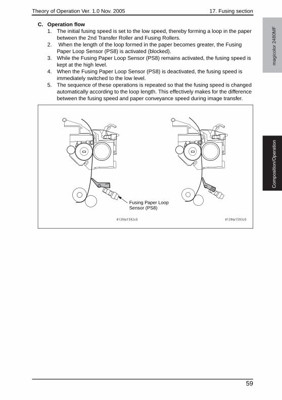
Theory of Operation Ver. 1.0 Nov. 2005 17. Fusing section
ma
gic
olo
r 2
48
0M
FC
om
po
sitio
n/O
pe
ratio
n
C. Operation flow1. The initial fusing speed is set to the low speed, thereby forming a loop in the paper
between the 2nd Transfer Roller and Fusing Rollers.2. When the length of the loop formed in the paper becomes greater, the Fusing
Paper Loop Sensor (PS8) is activated (blocked).3. While the Fusing Paper Loop Sensor (PS8) remains activated, the fusing speed is
kept at the high level.4. When the Fusing Paper Loop Sensor (PS8) is deactivated, the fusing speed is
immediately switched to the low level.5. The sequence of these operations is repeated so that the fusing speed is changed
automatically according to the loop length. This effectively makes for the difference between the fusing speed and paper conveyance speed during image transfer.
4139to1592c0 4139to1593c0
Fusing Paper Loop Sensor (PS8)
59
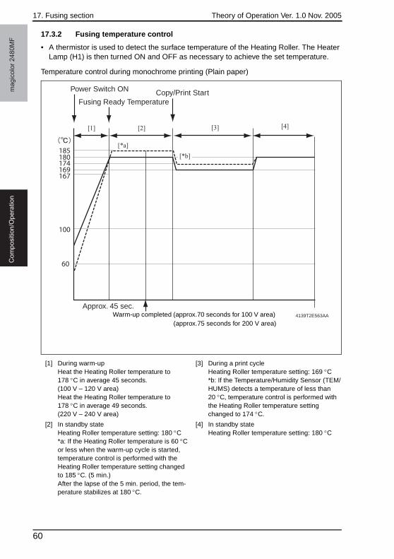
17. Fusing section Theory of Operation Ver. 1.0 Nov. 2005m
ag
ico
lor
24
80
MF
Co
mp
ositio
n/O
pe
ratio
n
17.3.2 Fusing temperature control
• A thermistor is used to detect the surface temperature of the Heating Roller. The Heater Lamp (H1) is then turned ON and OFF as necessary to achieve the set temperature.
Temperature control during monochrome printing (Plain paper)
[1] During warm-upHeat the Heating Roller temperature to 178 °C in average 45 seconds. (100 V – 120 V area)Heat the Heating Roller temperature to 178 °C in average 49 seconds. (220 V – 240 V area)
[3] During a print cycleHeating Roller temperature setting: 169 °C*b: If the Temperature/Humidity Sensor (TEM/HUMS) detects a temperature of less than 20 °C, temperature control is performed with the Heating Roller temperature setting changed to 174 °C.
[2] In standby stateHeating Roller temperature setting: 180 °C*a: If the Heating Roller temperature is 60 °C or less when the warm-up cycle is started, temperature control is performed with the Heating Roller temperature setting changed to 185 °C. (5 min.)After the lapse of the 5 min. period, the tem-perature stabilizes at 180 °C.
[4] In standby stateHeating Roller temperature setting: 180 °C
100
60
Approx. 45 sec.
169167
180185
174
Power Switch ON
Fusing Ready TemperatureCopy/Print Start
[3] [4][2]
[*a]
[1]
4139T2E563AA
[*b]
Warm-up completed (approx.70 seconds for 100 V area)(approx.75 seconds for 200 V area)
60
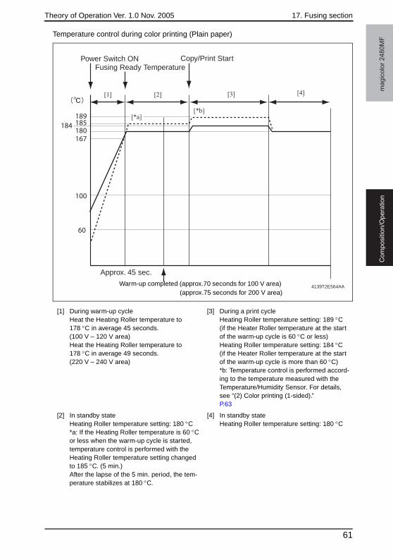
Theory of Operation Ver. 1.0 Nov. 2005 17. Fusing section
ma
gic
olo
r 2
48
0M
FC
om
po
sitio
n/O
pe
ratio
n
Temperature control during color printing (Plain paper)
[1] During warm-up cycleHeat the Heating Roller temperature to 178 °C in average 45 seconds. (100 V – 120 V area)Heat the Heating Roller temperature to 178 °C in average 49 seconds. (220 V – 240 V area)
[3] During a print cycleHeating Roller temperature setting: 189 °C (if the Heater Roller temperature at the start of the warm-up cycle is 60 °C or less)Heating Roller temperature setting: 184 °C (if the Heater Roller temperature at the start of the warm-up cycle is more than 60 °C)*b: Temperature control is performed accord-ing to the temperature measured with the Temperature/Humidity Sensor. For details, see “(2) Color printing (1-sided).”P.63
[2] In standby stateHeating Roller temperature setting: 180 °C*a: If the Heating Roller temperature is 60 °C or less when the warm-up cycle is started, temperature control is performed with the Heating Roller temperature setting changed to 185 °C. (5 min.)After the lapse of the 5 min. period, the tem-perature stabilizes at 180 °C.
[4] In standby stateHeating Roller temperature setting: 180 °C
100
60
Approx. 45 sec.
167
185184189
180
Power Switch ONFusing Ready Temperature
Copy/Print Start
[3] [4][2]
[*b]
[1]
4139T2E564AA
[*a]
Warm-up completed (approx.70 seconds for 100 V area)(approx.75 seconds for 200 V area)
61
17. Fusing section Theory of Operation Ver. 1.0 Nov. 2005m
ag
ico
lor
24
80
MF
Co
mp
ositio
n/O
pe
ratio
n
A. Warm-up• Control is provided until the Heating Roller temperature reaches 178 °C.• This control is performed when the Power Switch is turned ON, a malfunction or paper
misfeed is reset, the Energy Saver mode is canceled, or the door is opened and closed.
B. In standby• The fusing temperature in the standby state is prevented from being dropped.• The control temperature in the standby state after the warm-up cycle which was started
with the Heating Roller temperature 60 °C or less is changed to that of the ordinary standby after the lapse of a predetermined period of time.
*a: The fusing temperature in the standby state is changed if the standby state lasts for 20 min. or longer. Machine interior temperature is less than 20 °C: 170 °C Machine interior temperature is 20 °C or more: 165 °C
C. During print cycle• To ensure good fusing performance, the set temperature of each roller is varied accord-
ing to the paper type and environment.
(1) Monochrome printing• Temperature control is changed back to that listed under “Ordinary Environment” in the
table when the Temperature/Humidity Sensor (TEM/HUMS) detects 20 °C or more.
*a: The temperature is controlled at 159 °C if the machine interior temperature is 20 °C or more and humidity is 40% or higher.
Standby State Temperature (°C)
Ordinary standby 180*a
In standby state after the warm-up cycle started with the Heating Roller tem-perature below 60 °C
185
Media TypeOrdinary
environment (°C)
Temperature/humidity Sensor less than 20 °C
(°C)
Plain paper (plain paper, letterhead) 169 174
Plain paper (plain paper, letterhead) 257 mm or less 169 174
Thick stock (thick stock, postcards, labels) 169
OHP 169
Envelopes 194*a
Glossy stock 169
62
Theory of Operation Ver. 1.0 Nov. 2005 17. Fusing section
ma
gic
olo
r 2
48
0M
FC
om
po
sitio
n/O
pe
ratio
n
(2) Color printing (1-sided)• If the print cycle is started in a condition, in which the Temperature/Humidity Sensor
(TEM/HUMS) detects 20 °C or more, control is returned back to one having a control temperature of more than 60 °C after five printed pages have been produced.
*a: The temperature is controlled at 159 °C if the machine interior temperature is 20 °C or more and humidity is 40% or higher.
D. Energy Saver mode• Heater control is suspended when a malfunction or paper misfeed occurs or in the
Energy Saver mode.
(1) Control start timing• The door is opened or a malfunction or paper misfeed occurs• A request for Energy Saver mode is granted
(2) Control termination timing• All of the following events are canceled: door open, an error or malfunction that has
occurred, and Energy Saver mode.
Media Type
Heating Roller temperature at
the start of warm-up cycle
Ordinary environment
(°C)
Temperature/humidity Sensor less than 20 °C
(°C)
Temperature/humidity Sensor 28 °C or more
(°C)
Plain paper (plain paper, letterhead)
60 °C or less 189 194 189
More than 60 °C 184 194 184
Plain paper (plain paper, letter-head) 257 mm or less
60 °C or less 189 194 189
More than 60 °C 184 194 184
Thick stock (thick stock, postcards, labels)
- 184
OHP - 179
Envelopes - 194*a
Glossy stock - 190 190 185
63
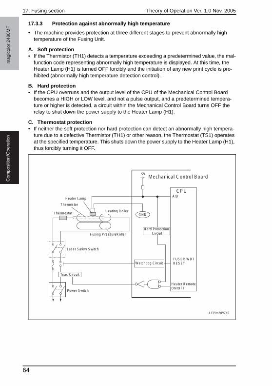
17. Fusing section Theory of Operation Ver. 1.0 Nov. 2005m
ag
ico
lor
24
80
MF
Co
mp
ositio
n/O
pe
ratio
n
17.3.3 Protection against abnormally high temperature
• The machine provides protection at three different stages to prevent abnormally high temperature of the Fusing Unit.
A. Soft protection• If the Thermistor (TH1) detects a temperature exceeding a predetermined value, the mal-
function code representing abnormally high temperature is displayed. At this time, the Heater Lamp (H1) is turned OFF forcibly and the initiation of any new print cycle is pro-hibited (abnormally high temperature detection control).
B. Hard protection• If the CPU overruns and the output level of the CPU of the Mechanical Control Board
becomes a HIGH or LOW level, and not a pulse output, and a predetermined tempera-ture or higher is detected, a circuit within the Mechanical Control Board turns OFF the relay to shut down the power supply to the Heater Lamp (H1).
C. Thermostat protection• If neither the soft protection nor hard protection can detect an abnormally high tempera-
ture due to a defective Thermistor (TH1) or other reason, the Thermostat (TS1) operates at the specified temperature. This shuts down the power supply to the Heater Lamp (H1), thus forcibly turning it OFF.
Triac Circuit
Power Switch
Watchdog Circuit
A/D
FUSER WDT RESET
Heater Remote ON/OFF
Heating Roller
Fusing PressureRoller
Thermostat
Laser Safety Switch
Heater Lamp
Thermistor
GND
5VMechanical Control Board
CPU
Hard Protection Circuit
4139to2097e0
64
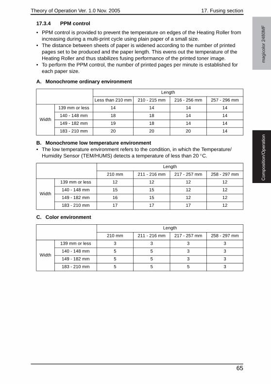
Theory of Operation Ver. 1.0 Nov. 2005 17. Fusing section
ma
gic
olo
r 2
48
0M
FC
om
po
sitio
n/O
pe
ratio
n
17.3.4 PPM control
• PPM control is provided to prevent the temperature on edges of the Heating Roller from increasing during a multi-print cycle using plain paper of a small size.
• The distance between sheets of paper is widened according to the number of printed pages set to be produced and the paper length. This evens out the temperature of the Heating Roller and thus stabilizes fusing performance of the printed toner image.
• To perform the PPM control, the number of printed pages per minute is established for each paper size.
A. Monochrome ordinary environment
B. Monochrome low temperature environment• The low temperature environment refers to the condition, in which the Temperature/
Humidity Sensor (TEM/HUMS) detects a temperature of less than 20 °C.
C. Color environment
Length
Less than 210 mm 210 - 215 mm 216 - 256 mm 257 - 296 mm
Width
139 mm or less 14 14 14 14
140 - 148 mm 18 18 14 14
149 - 182 mm 19 18 14 14
183 - 210 mm 20 20 20 14
Length
210 mm 211 - 216 mm 217 - 257 mm 258 - 297 mm
Width
139 mm or less 12 12 12 12
140 - 148 mm 15 15 12 12
149 - 182 mm 16 15 12 12
183 - 210 mm 17 17 17 12
Length
210 mm 211 - 216 mm 217 - 257 mm 258 - 297 mm
Width
139 mm or less 3 3 3 3
140 - 148 mm 5 5 3 3
149 - 182 mm 5 5 3 3
183 - 210 mm 5 5 5 3
65
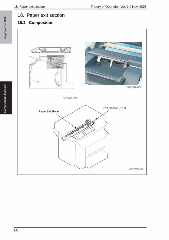
18. Paper exit section Theory of Operation Ver. 1.0 Nov. 2005m
ag
ico
lor
24
80
MF
Co
mp
ositio
n/O
pe
ratio
n
18. Paper exit section
18.1 Composition
4139T2C510AA
4139T2C552AA
4139T2C558AA
Exit Sensor (PS7)Paper Exit Roller
66
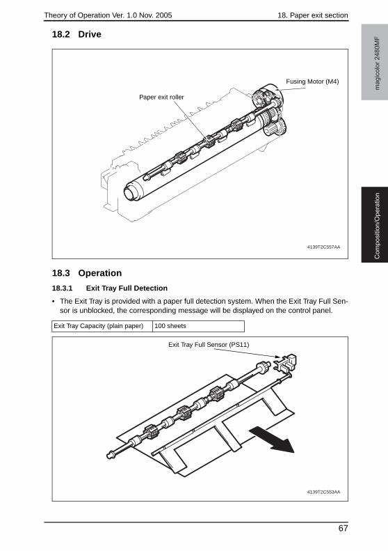
Theory of Operation Ver. 1.0 Nov. 2005 18. Paper exit section
ma
gic
olo
r 2
48
0M
FC
om
po
sitio
n/O
pe
ratio
n
18.2 Drive
18.3 Operation
18.3.1 Exit Tray Full Detection
• The Exit Tray is provided with a paper full detection system. When the Exit Tray Full Sen-sor is unblocked, the corresponding message will be displayed on the control panel.
4139T2C557AA
Paper exit roller
Fusing Motor (M4)
Exit Tray Capacity (plain paper) 100 sheets
4139T2C553AA
Exit Tray Full Sensor (PS11)
67
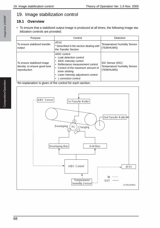
19. Image stabilization control Theory of Operation Ver. 1.0 Nov. 2005m
ag
ico
lor
24
80
MF
Co
mp
ositio
n/O
pe
ratio
n
19. Image stabilization control
19.1 Overview
• To ensure that a stabilized output image is produced at all times, the following image sta-bilization controls are provided.
*An explanation is given of the control for each section.
Purpose Control Detection
To ensure stabilized transfer output
ATVC* Described in the section dealing with the Transfer Section
Temperature/ humidity Sensor (TEM/HUMS)
To ensure stabilized image density; to ensure good tone reproduction
AIDC control• Leak detection control• AIDC intensity control• Reflectance measurement control• Control of the maximum amount of
toner sticking• Laser intensity adjustment control• γ correction control
IDC Sensor (IDC)Temperature/ humidity Sensor (TEM/HUMS)
4139to2098e0
INOUT
1st Transfer Roller
2nd Transfer Roller
ATVC
Grid BiasDeveloping Bias
Developing ChargingPC
AIDC Sensor
Temperature/humidity Sensor
AIDC Control
68
Theory of Operation Ver. 1.0 Nov. 2005 19. Image stabilization control
ma
gic
olo
r 2
48
0M
FC
om
po
sitio
n/O
pe
ratio
n
19.2 Operation
19.2.1 Leak detection control
• For the clearance between the Photo Conductor and Developing Roller, an optimum developing bias voltage is established that does not result in a leak image or uneven density.
19.2.2 AIDC Sensor LED intensity control
• The following adjustment is made to correct any changes in characteristics occurring due to change with time and contamination of the IDC Sensor (IDC): the intensity of the LED is adjusted for the surface of the Transfer Belt on which no toner sticks, so that the output value of the IDC Sensor (IDC) becomes constant.
19.2.3 Reflectance measurement control
• The reflectance of the Image Transfer Belt is measured using the IDC Sensor (IDC). One measurement is taken for one complete turn of the Image Transfer Belt.
• The measured value is corrected during the laser intensity adjustment control and γ cor-rection control.
19.2.4 Control of the maximum amount of toner sticking
• The developing bias setting value is adjusted to keep constant the amount of toner stick-ing to the surface of the Photo Conductor with reference to the 100% solid image.
19.2.5 Laser intensity adjustment control
• Characteristics of the Photo Conductor, developing, and charging change as affected by changes with time and in environment. The intensity of the laser light is adjusted so that fine lines and gradations of a predetermined level are reproduced at all times.
19.2.6 γ correction control
• A gradation pattern is produced on the surface of the Image Transfer Belt. The IDC Sen-sor (IDC) measures the density of the pattern and sends the measured result to the con-troller for gradation adjustment.
69
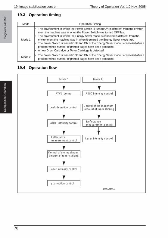
19. Image stabilization control Theory of Operation Ver. 1.0 Nov. 2005m
ag
ico
lor
24
80
MF
Co
mp
ositio
n/O
pe
ratio
n
19.3 Operation timing
19.4 Operation flow
Mode Operation Timing
Mode 1
• The environment in which the Power Switch is turned ON is different from the environ-ment the machine was in when the Power Switch was turned OFF last.
• The environment in which the Energy Saver mode is canceled is different from the environment the machine was in when it entered the Energy Saver mode last.
• The Power Switch is turned OFF and ON or the Energy Saver mode is canceled after a predetermined number of printed pages have been produced.
• A new Drum Cartridge or Toner Cartridge is detected.
Mode 2• The Power Switch is turned OFF and ON or the Energy Saver mode is canceled after a
predetermined number of printed pages have been produced.
Mode 2
AIDC intensity control
Reflectance measurement control
Laser intensity control
Mode 1
ATVC control
Leak detection control
AIDC intensity control
Reflectance measurement control
Control of the maximum amount of toner sticking
Control of the maximum amount of toner sticking
Laser intensity control
γ correction control
4139to2099e0
70
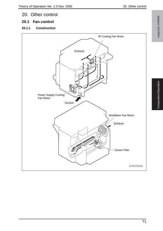
Theory of Operation Ver. 1.0 Nov. 2005 20. Other control
ma
gic
olo
r 2
48
0M
FC
om
po
sitio
n/O
pe
ratio
n
20. Other control
20.1 Fan control
20.1.1 Construction
4139T2C554AA
Suction
Exhaust
Ozone Filter
Power Supply Cooling Fan Motor
Ventilation Fan Motor
IR Cooling Fan Motor
Exhaust
71
20. Other control Theory of Operation Ver. 1.0 Nov. 2005m
ag
ico
lor
24
80
MF
Co
mp
ositio
n/O
pe
ratio
n
20.1.2 Control
A. Power Supply Cooling Fan Motor<Full-speed conditions>• For the predetermined period of time after the Power Switch has been turned ON• For the specified period of time up to the end of Energy Saver mode• At the start of a print cycle (full-speed rotation after the lapse of a predetermined period
of time of half-speed rotation). No full-speed rotation is performed if the print cycle is completed during half-speed rotation.
<Half-speed conditions>• At the end of a print cycle (half-speed rotation after the lapse of a predetermined period
of time of full-speed rotation)• Half-speed rotation under any condition other than above
<Stop conditions>• In Energy Saver mode• The Power Supply Cooling Fan Motor (FM1) develops a malfunction
B. Ventilation Fan Motor<Full-speed condition>• While the Main Motor (M1) remains energized
<Stop conditions>• The lapse of a predetermined period of time after the Main Motor (M1) has been deener-
gized• Stop under any condition other than above
<Forced stop condition>• A door is opened, a paper misfeed has occurred, or a malfunction has occurred.
C. IR Cooling Fan Motor<Full-speed conditions>• For the predetermined period of time after the Power Switch has been turned ON• At the start of a print cycle (full-speed rotation after the lapse of a predetermined period
of time of half-speed rotation)
<Half-speed conditions>• At the end of a print cycle (half-speed rotation after the lapse of a predetermined period
of time of full-speed rotation)• Half-speed rotation under any condition other than above
72
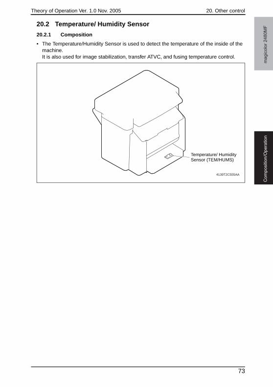
Theory of Operation Ver. 1.0 Nov. 2005 20. Other control
ma
gic
olo
r 2
48
0M
FC
om
po
sitio
n/O
pe
ratio
n
20.2 Temperature/ Humidity Sensor
20.2.1 Composition
• The Temperature/Humidity Sensor is used to detect the temperature of the inside of the machine.It is also used for image stabilization, transfer ATVC, and fusing temperature control.
4139T2C555AA
Temperature/ Humidity Sensor (TEM/HUMS)
73

20. Other control Theory of Operation Ver. 1.0 Nov. 2005m
ag
ico
lor
24
80
MF
Co
mp
ositio
n/O
pe
ratio
n
Blank Page
74

SERVICE MANUAL
2005.11Ver. 1.0
Auto Document Feeder Unit
THEORY OF OPERATION

Revision historyAfter publication of this service manual, the parts and mechanism may be subject to change forimprovement of their performance. Therefore, the descriptions given in this service manual may not coincide with the actual machine.
When any change has been made to the descriptions in the service manual, a revised version will beissued with a revision mark added as required.
Revision mark:• To indicate clearly a section revised, show to the left of the revised section.
A number within represents the number of times the revision has been made.
• To indicate clearly a section revised, show in the lower outside section of the correspond-ing page. A number within represents the number of times the revision has been made.
NOTERevision marks shown in a page are restricted only to the latest ones with the old ones deleted.
• When a page revised in Ver. 2.0 has been changed in Ver. 3.0: The revision marks for Ver. 3.0 only are shown with those for Ver. 2.0 deleted.
• When a page revised in Ver. 2.0 has not been changed in Ver. 3.0: The revision marks for Ver. 2.0 are left as they are.
11
1
1
2005/11 1.0 — Issue of the first edition
Date Service manual Ver. Revision mark Descriptions of revision
Au
to D
ocu
me
nt
Fe
ed
er
Un
itO
utlin
eC
om
po
sitio
n/O
pe
ratio
n
Theory of Operation Ver. 1.0 Nov. 2005
CONTENTS
Auto Document Feeder Unit
Outline1. Product Specifications............................................................................................. 1
Composition/Operation2. Composition ............................................................................................................ 3
3. Drive........................................................................................................................ 4
4. Mechanical operations ............................................................................................ 5
4.1 Document Take-up Mechanism ............................................................................ 5
4.1.1 Document Take-up Mechanism..................................................................... 5
4.1.2 Document Separation Mechanism................................................................ 6
4.2 Document Transport/Exit Mechanism................................................................... 7
4.2.1 Document transport mechanism................................................................... 7
4.2.2 Document exit mechanism............................................................................ 8
4.3 Miscellaneous....................................................................................................... 9
4.3.1 Document Feeder raised/lowered position detection mechanism................. 9
i
Au
to D
ocu
me
nt
Fe
ed
er
Un
itO
utlin
eC
om
po
sitio
n/O
pe
ratio
nTheory of Operation Ver. 1.0 Nov. 2005
Blank Page
ii
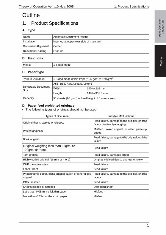
Theory of Operation Ver. 1.0 Nov. 2005 1. Product Specifications
Ou
tlin
eA
uto
Do
cu
me
nt
Fe
ed
er
Un
it
Outline1. Product SpecificationsA. Type
B. Functions
C. Paper type
D. Paper feed prohibited originals• The following types of originals should not be used.
Name Automatic Document Feeder
Installation Inserted at upper-rear side of main unit
Document Alignment Center
Document Loading Face up
Modes 1-Sided Mode
Type of Document 1-Sided mode (Plain Paper): 35 g/m2 to 128 g/m2
Detectable Document Size
A5S, B5S, A4S, LegalS, LetterS
Width 140 to 216 mm
Length 148 to 355.6 mm
Capacity 50 sheets (80 g/m2) or load height of 8 mm or less.
Types of Document Possible Malfunctions
Original that is stapled or clipped.Feed failure, damage to the original, or drive failure due to clip clogging
Pasted originalsMisfeed, broken original, or folded paste-up edges
Book originalFeed failure, damage to the original, or drive failure
Original weighing less than 35g/m2 or129g/m2 or more
Feed failure
Torn original Feed failure, damaged sheet
Highly curled original (15 mm or more) Original misfeed due to dog-ear or skew
OHP transparencies Feed failure
Label Sheet Feed failure
Photographic paper, gloss enamel paper, or other gloss original
Feed failure, damage to the original, or drive failure
Offset master Feed failure
Sheets clipped or notched Damaged sheet
Less-than-0.05-mm-thick thin paper Misfeed
More-than-0.15-mm-thick thin paper Misfeed
1
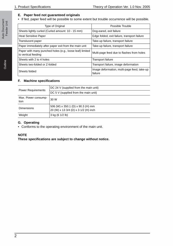
1. Product Specifications Theory of Operation Ver. 1.0 Nov. 2005O
utlin
eA
uto
Do
cu
me
nt
Fe
ed
er
Un
it
E. Paper feed not guaranteed originals• If fed, paper feed will be possible to some extent but trouble occurrence will be possible.
F. Machine specifications
G. Operating• Conforms to the operating environment of the main unit.
NOTEThese specifications are subject to change without notice.
Type of Original Possible Trouble
Sheets lightly curled (Curled amount: 10 - 15 mm) Dog-eared, exit failure
Heat Sensitive Paper Edge folded, exit failure, transport failure
Translucent paper Take-up failure, transport failure
Paper immediately after paper exit from the main unit Take-up failure, transport failure
Paper with many punched holes (e.g., loose leaf) limited to vertical feeding
Multi-page feed due to flashes from holes
Sheets with 2 to 4 holes Transport failure
Sheets two-folded or Z-folded Transport failure, image deformation
Sheets foldedImage deformation, multi-page feed, take-up failure
Power RequirementsDC 24 V (supplied from the main unit)
DC 5 V (supplied from the main unit)
Max. Power consump-tion
30 W
Dimensions506 (W) x 350.1 (D) x 90.3 (H) mm20 (W) x 13 3/4 (D) x 3 1/2 (H) inch
Weight 3 kg (6 1/2 lb)
2
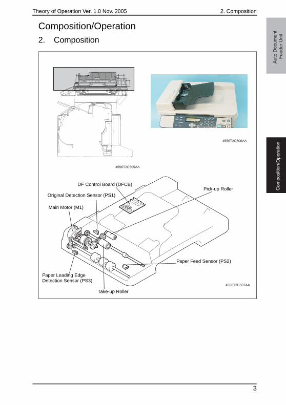
Theory of Operation Ver. 1.0 Nov. 2005 2. Composition
Co
mp
ositio
n/O
pe
ratio
nA
uto
Do
cu
me
nt
Fe
ed
er
Un
it
Composition/Operation2. Composition
4556T2C505AA
4556T2C506AA
4556T2C507AA
Main Motor (M1)
DF Control Board (DFCB)
Paper Feed Sensor (PS2)
Paper Leading Edge Detection Sensor (PS3)
Original Detection Sensor (PS1)
Take-up Roller
Pick-up Roller
3

3. Drive Theory of Operation Ver. 1.0 Nov. 2005A
uto
Do
cu
me
nt
Fe
ed
er
Un
itC
om
po
sitio
n/O
pe
ratio
n
3. Drive
4556T2C508AA
4
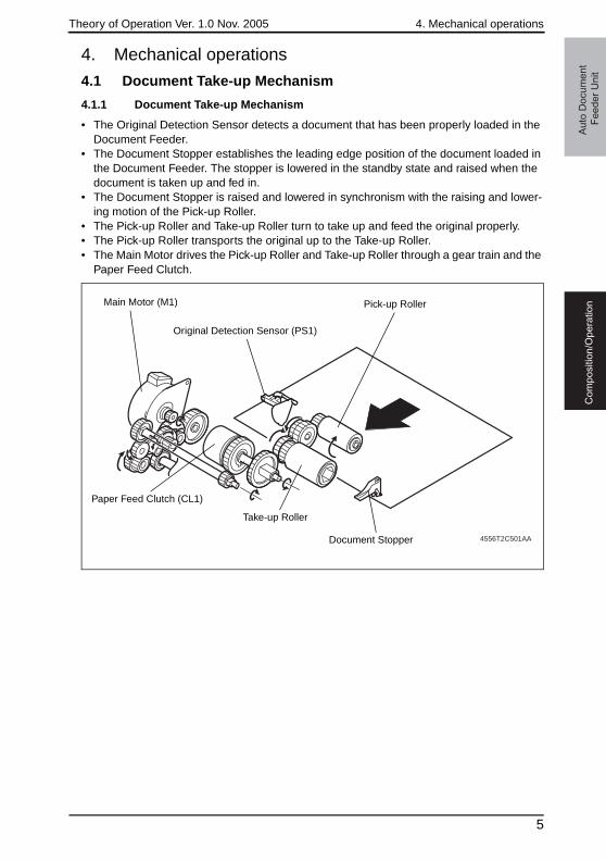
Theory of Operation Ver. 1.0 Nov. 2005 4. Mechanical operations
Co
mp
ositio
n/O
pe
ratio
nA
uto
Do
cu
me
nt
Fe
ed
er
Un
it
4. Mechanical operations
4.1 Document Take-up Mechanism
4.1.1 Document Take-up Mechanism
• The Original Detection Sensor detects a document that has been properly loaded in the Document Feeder.
• The Document Stopper establishes the leading edge position of the document loaded in the Document Feeder. The stopper is lowered in the standby state and raised when the document is taken up and fed in.
• The Document Stopper is raised and lowered in synchronism with the raising and lower-ing motion of the Pick-up Roller.
• The Pick-up Roller and Take-up Roller turn to take up and feed the original properly.• The Pick-up Roller transports the original up to the Take-up Roller.• The Main Motor drives the Pick-up Roller and Take-up Roller through a gear train and the
Paper Feed Clutch.
4556T2C501AA
Main Motor (M1) Pick-up Roller
Take-up Roller
Paper Feed Clutch (CL1)
Document Stopper
Original Detection Sensor (PS1)
5
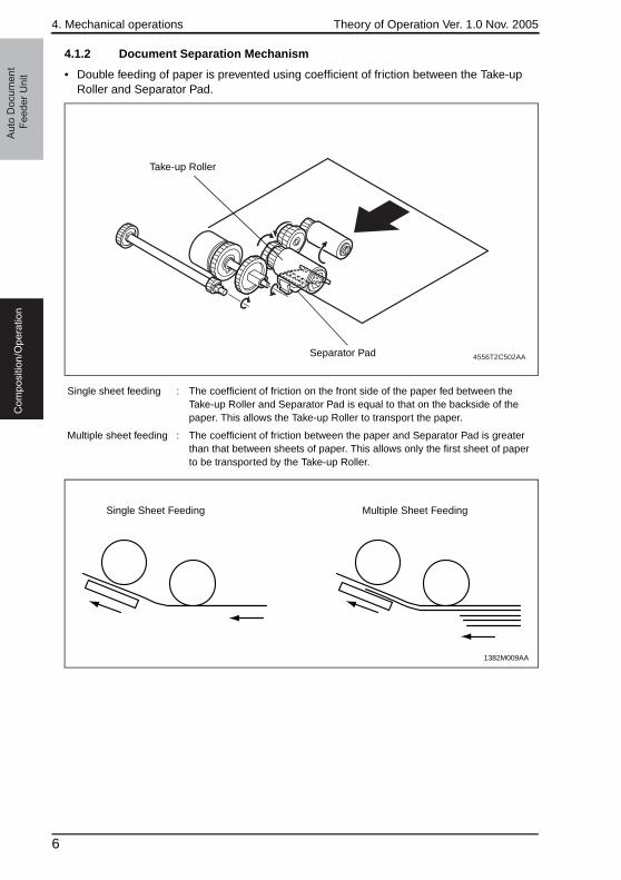
4. Mechanical operations Theory of Operation Ver. 1.0 Nov. 2005A
uto
Do
cu
me
nt
Fe
ed
er
Un
itC
om
po
sitio
n/O
pe
ratio
n
4.1.2 Document Separation Mechanism
• Double feeding of paper is prevented using coefficient of friction between the Take-up Roller and Separator Pad.
Single sheet feeding : The coefficient of friction on the front side of the paper fed between the Take-up Roller and Separator Pad is equal to that on the backside of the paper. This allows the Take-up Roller to transport the paper.
Multiple sheet feeding : The coefficient of friction between the paper and Separator Pad is greater than that between sheets of paper. This allows only the first sheet of paper to be transported by the Take-up Roller.
4556T2C502AASeparator Pad
Take-up Roller
1382M009AA
Single Sheet Feeding Multiple Sheet Feeding
6
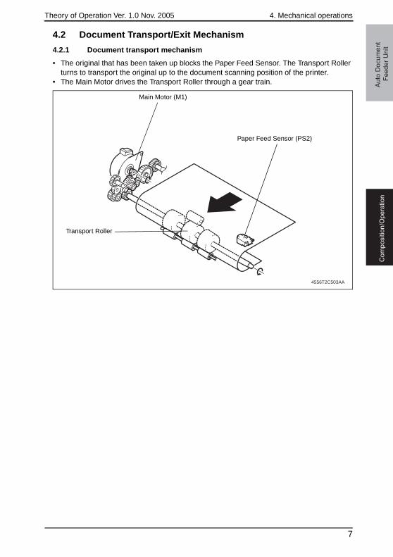
Theory of Operation Ver. 1.0 Nov. 2005 4. Mechanical operations
Co
mp
ositio
n/O
pe
ratio
nA
uto
Do
cu
me
nt
Fe
ed
er
Un
it
4.2 Document Transport/Exit Mechanism
4.2.1 Document transport mechanism
• The original that has been taken up blocks the Paper Feed Sensor. The Transport Roller turns to transport the original up to the document scanning position of the printer.
• The Main Motor drives the Transport Roller through a gear train.
4556T2C503AA
Main Motor (M1)
Transport Roller
Paper Feed Sensor (PS2)
7
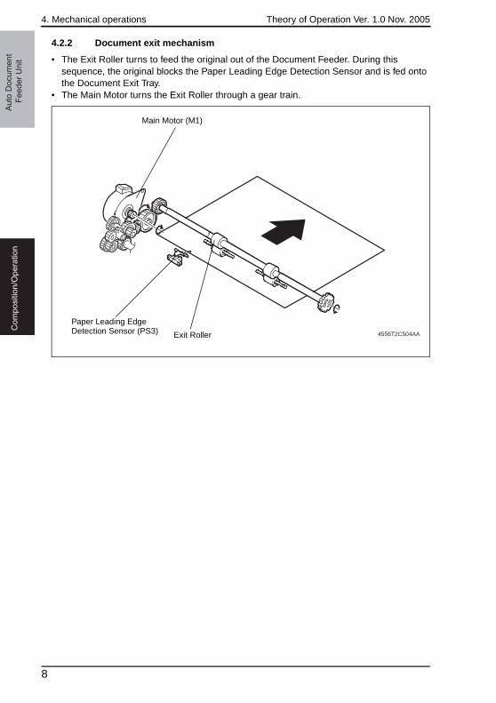
4. Mechanical operations Theory of Operation Ver. 1.0 Nov. 2005A
uto
Do
cu
me
nt
Fe
ed
er
Un
itC
om
po
sitio
n/O
pe
ratio
n
4.2.2 Document exit mechanism
• The Exit Roller turns to feed the original out of the Document Feeder. During this sequence, the original blocks the Paper Leading Edge Detection Sensor and is fed onto the Document Exit Tray.
• The Main Motor turns the Exit Roller through a gear train.
4556T2C504AA
Main Motor (M1)
Exit Roller
Paper Leading Edge Detection Sensor (PS3)
8

Theory of Operation Ver. 1.0 Nov. 2005 4. Mechanical operations
Co
mp
ositio
n/O
pe
ratio
nA
uto
Do
cu
me
nt
Fe
ed
er
Un
it
4.3 Miscellaneous
4.3.1 Document Feeder raised/lowered position detection mechanism
• There is a magnet provided in the Document Feeder, allowing the printer to detect the position of the Document Feeder whether the Document Feeder is raised or lowered.
• This magnet attracts the Original Cover Set Switch provided on the printer side, thus acti-vating the sensor. The printer will then detect the position of the Document Feeder.
4139T2C561AA
Original Cover Set Switch (SW4)
Magnet
9

4. Mechanical operations Theory of Operation Ver. 1.0 Nov. 2005A
uto
Do
cu
me
nt
Fe
ed
er
Un
itC
om
po
sitio
n/O
pe
ratio
n
Blank Page
10

SERVICE MANUAL
2005.11Ver. 1.0
Lower Feeder Unit
THEORY OF OPERATION

Revision historyAfter publication of this service manual, the parts and mechanism may be subject to change forimprovement of their performance. Therefore, the descriptions given in this service manual may not coincide with the actual machine.
When any change has been made to the descriptions in the service manual, a revised version will beissued with a revision mark added as required.
Revision mark:• To indicate clearly a section revised, show to the left of the revised section.
A number within represents the number of times the revision has been made.
• To indicate clearly a section revised, show in the lower outside section of the correspond-ing page. A number within represents the number of times the revision has been made.
NOTERevision marks shown in a page are restricted only to the latest ones with the old ones deleted.
• When a page revised in Ver. 2.0 has been changed in Ver. 3.0: The revision marks for Ver. 3.0 only are shown with those for Ver. 2.0 deleted.
• When a page revised in Ver. 2.0 has not been changed in Ver. 3.0: The revision marks for Ver. 2.0 are left as they are.
11
1
1
2005/11 1.0 — Issue of the first edition
Date Service manual Ver. Revision mark Descriptions of revision
Lo
we
r F
ee
de
r U
nit
Ou
tlin
eC
om
po
sitio
n/O
pe
ratio
n
Theory of Operation Ver. 1.0 Nov. 2005
CONTENTS
Lower Feeder Unit
Outline1. Product specifications ............................................................................................. 1
Composition/Operation2. Composition ............................................................................................................ 3
3. Drive........................................................................................................................ 4
4. Mechanical operation .............................................................................................. 5
4.1 Conveyance Drive Mechanism ............................................................................. 5
4.2 Paper Empty Detection......................................................................................... 6
4.3 Tray Set Detection ................................................................................................ 7
i

Lo
we
r F
ee
de
r U
nit
Ou
tlin
eC
om
po
sitio
n/O
pe
ratio
nTheory of Operation Ver. 1.0 Nov. 2005
Blank Page
ii
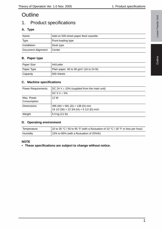
Theory of Operation Ver. 1.0 Nov. 2005 1. Product specifications
Ou
tlin
eL
ow
er
Fe
ed
er
Un
it
Outline1. Product specificationsA. TypeB. Paper type
C. Machine specifications
D. Operating environment
NOTE• These specifications are subject to change without notice.
Name Add-on 500-sheet paper feed cassette
Type Front-loading type
Installation Desk type
Document Alignment Center
Paper Size A4/Letter
Paper Type Plain paper: 60 to 90 g/m2 (16 to 24 lb)
Capacity 500 sheets
Power Requirements DC 24 V ± 10% (supplied from the main unit)
DC 5 V ± 5%
Max. Power Consumption
12 W
Dimensions 495 (W) × 581 (D) × 138 (H) mm 19 1/2 (W) × 22 3/4 (H) × 5 1/2 (D) inch
Weight 5.0 kg (11 lb)
Temperature 10 to 35 °C / 50 to 95 °F (with a fluctuation of 10 °C / 18 °F or less per hour)
Humidity 15% to 85% (with a fluctuation of 20%/h)
1

1. Product specifications Theory of Operation Ver. 1.0 Nov. 2005O
utlin
eL
ow
er
Fe
ed
er
Un
it
Blank Page
2
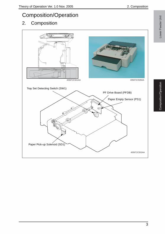
Theory of Operation Ver. 1.0 Nov. 2005 2. Composition
Co
mp
ositio
n/O
pe
ratio
nL
ow
er
Fe
ed
er
Un
it
Composition/Operation2. Composition4056T2C509AA4056T2C501AA
4056T2C502AA
PF Drive Board (PFDB)
Paper Empty Sensor (PS1)
Tray Set Detecting Switch (SW1)
Paper Pick-up Solenoid (SD1)
3
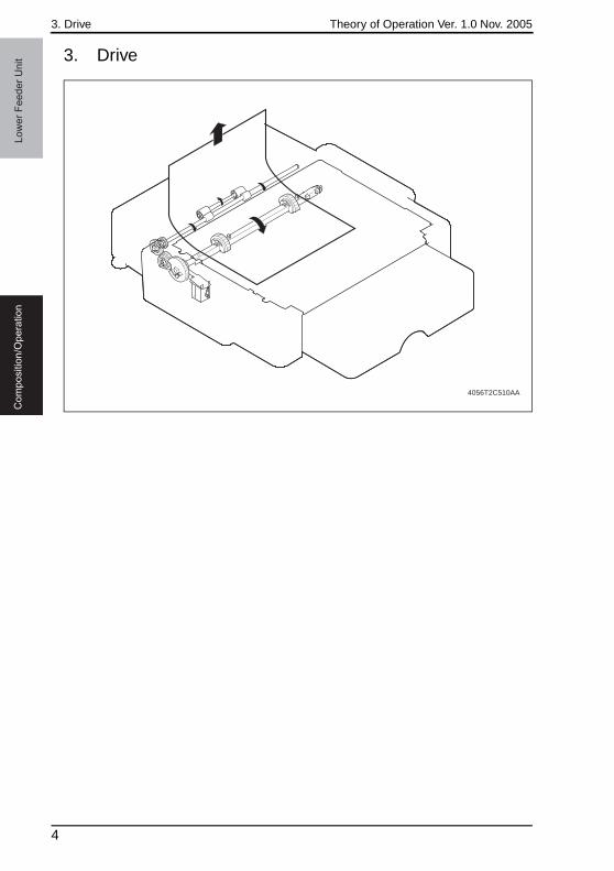
3. Drive Theory of Operation Ver. 1.0 Nov. 2005L
ow
er
Fe
ed
er
Un
itC
om
po
sitio
n/O
pe
ratio
n
3. Drive
4056T2C510AA
4
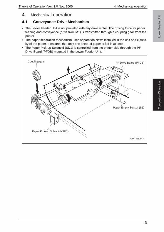
Theory of Operation Ver. 1.0 Nov. 2005 4. Mechanical operation
Co
mp
ositio
n/O
pe
ratio
nL
ow
er
Fe
ed
er
Un
it
4. Mechanical operation4.1 Conveyance Drive Mechanism
• The Lower Feeder Unit is not provided with any drive motor. The driving force for paper feeding and conveyance (drive from M1) is transmitted through a coupling gear from the printer.
• The paper separation mechanism uses separation claws installed in the unit and elastic-ity of the paper. It ensures that only one sheet of paper is fed in at time.
• The Paper Pick-up Solenoid (SD1) is controlled from the printer side through the PF Drive Board (PFDB) mounted in the Lower Feeder Unit.
4056T2E506AA
Paper Pick-up Solenoid (SD1)
PF Drive Board (PFDB)
Paper Empty Sensor (S1)
Coupling gear
5
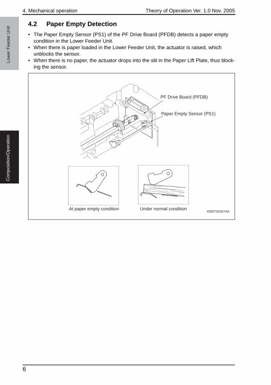
4. Mechanical operation Theory of Operation Ver. 1.0 Nov. 2005L
ow
er
Fe
ed
er
Un
itC
om
po
sitio
n/O
pe
ratio
n
4.2 Paper Empty Detection
• The Paper Empty Sensor (PS1) of the PF Drive Board (PFDB) detects a paper empty condition in the Lower Feeder Unit.
• When there is paper loaded in the Lower Feeder Unit, the actuator is raised, which unblocks the sensor.
• When there is no paper, the actuator drops into the slit in the Paper Lift Plate, thus block-ing the sensor.
4056T2E507AA
PF Drive Board (PFDB)
At paper empty condition Under normal condition
Paper Empty Sensor (PS1)
6
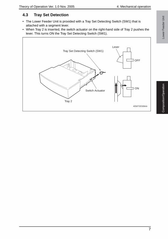
Theory of Operation Ver. 1.0 Nov. 2005 4. Mechanical operation
Co
mp
ositio
n/O
pe
ratio
nL
ow
er
Fe
ed
er
Un
it
4.3 Tray Set Detection• The Lower Feeder Unit is provided with a Tray Set Detecting Switch (SW1) that is attached with a segment lever.
• When Tray 2 is inserted, the switch actuator on the right-hand side of Tray 2 pushes the lever. This turns ON the Tray Set Detecting Switch (SW1).
Tray Set Detecting Switch (SW1)
Switch Actuator
Tray 2
Lever
OFF
ON
4056T2E508AA
7

4. Mechanical operation Theory of Operation Ver. 1.0 Nov. 2005L
ow
er
Fe
ed
er
Un
itC
om
po
sitio
n/O
pe
ratio
n
Blank Page
8

SERVICE MANUAL
2005.11Ver. 1.0
Duplex OptionTHEORY OF OPERATION

Revision historyAfter publication of this service manual, the parts and mechanism may be subject to change forimprovement of their performance. Therefore, the descriptions given in this service manual may not coincide with the actual machine.
When any change has been made to the descriptions in the service manual, a revised version will beissued with a revision mark added as required.
Revision mark:• To indicate clearly a section revised, show to the left of the revised section.
A number within represents the number of times the revision has been made.
• To indicate clearly a section revised, show in the lower outside section of the correspond-ing page. A number within represents the number of times the revision has been made.
NOTERevision marks shown in a page are restricted only to the latest ones with the old ones deleted.
• When a page revised in Ver. 2.0 has been changed in Ver. 3.0: The revision marks for Ver. 3.0 only are shown with those for Ver. 2.0 deleted.
• When a page revised in Ver. 2.0 has not been changed in Ver. 3.0: The revision marks for Ver. 2.0 are left as they are.
11
1
1
2005/11 1.0 — Issue of the first edition
Date Service manual Ver. Revision mark Descriptions of revision
Du
ple
x O
ptio
nO
utlin
eC
om
po
sitio
n/O
pe
ratio
n
Theory of Operation Ver. 1.0 Nov. 2005
CONTENTS
Duplex Option
Outline1. Product specifications ............................................................................................. 1
Composition/Operation2. Composition ............................................................................................................ 3
3. Drive........................................................................................................................ 4
4. Mechanical operations ............................................................................................ 5
4.1 Switchback mechanism ........................................................................................ 5
4.1.1 Switchback operation .................................................................................... 5
4.1.2 Paper exit roller drive coupling mechanism................................................... 6
4.1.3 Switchback Motor Control ............................................................................. 6
4.2 Transport and duplex paper take-up mechanism.................................................. 7
4.2.1 Transport and duplex paper take-up operation ............................................. 7
4.2.2 Duplex Option Transport Motor Control......................................................... 7
4.2.3 Duplex Option Loop Correction Control ........................................................ 7
4.3 2-sided printing method ........................................................................................ 8
4.3.1 Operations in 2-sided printing with a single sheet of paper resident in the system......................................................................... 8
4.3.2 Operations in 2-sided printing with two sheets of paper resident in the system....................................................................... 10
i

Du
ple
x O
ptio
nO
utlin
eC
om
po
sitio
n/O
pe
ratio
nTheory of Operation Ver. 1.0 Nov. 2005
Blank Page
ii

Theory of Operation Ver. 1.0 Nov. 2005 1. Product specifications
Ou
tlin
eD
up
lex O
ptio
n
Outline1. Product specificationsA. Type
B. Paper type
C. Machine specifications
D. Operating environment
NOTE• These specifications are subject to change without notice.
Name Duplex Option
Type Switchback and Circulating Duplex Unit
Installation Mounted on the right side door of main unit
Reversing System Exit Roller switchback
Conveyance system Rubber roller + driven rolls
Document Alignment Center
Paper Size A4/Letter
Paper Type• Plain paper: 60 to 90 g/m2 (16 to 24 lb)• Recycled paper: 60 to 90 g/m2 (16 to 24 lb)
Power RequirementsDC 24 V ± 10% (supplied from the main unit)
DC 5 V ± 5% (supplied from the main unit)
Max. Power Consumption
42 W
Dimensions370 (W) × 153 (D) × 327 (H) mm14 1/2 (W) × 6 (D) × 12 3/4 (H) inch
Weight Approx. 2.3 kg (5 lb)
Temperature 10 to 35 °C / 50 to 95 °F (with a fluctuation of 10 °C / 18 °F or less per hour)
Humidity 15% to 85% (with a fluctuation of 20%/h)
1

1. Product specifications Theory of Operation Ver. 1.0 Nov. 2005O
utlin
eD
up
lex O
ptio
n
Blank Page
2
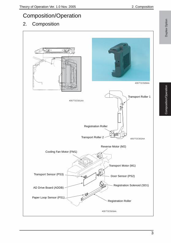
Theory of Operation Ver. 1.0 Nov. 2005 2. Composition
Co
mp
ositio
n/O
pe
ratio
nD
up
lex O
ptio
n
Composition/Operation2. Composition
4057T2C509AA
4057T2C502AA
4057T2C501AA
4057T2C503AA
Transport Roller 1
Registration Roller
Transport Roller 2
Cooling Fan Motor (FM1)
Reverse Motor (M2)
Transport Motor (M1)
Door Sensor (PS2)
Registration Solenoid (SD1)
Registration RollerPaper Loop Sensor (PS1)
AD Drive Board (ADDB)
Transport Sensor (PS3)
3
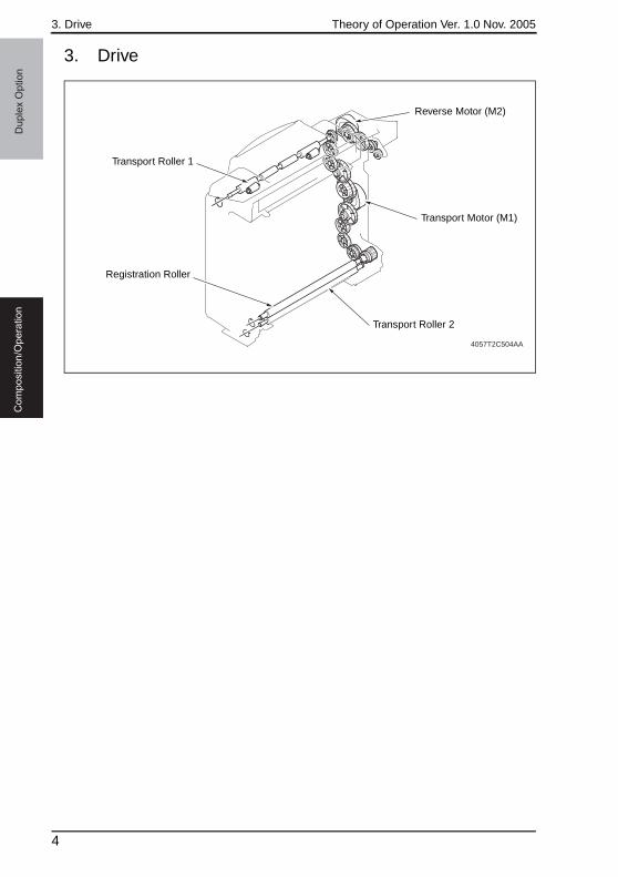
3. Drive Theory of Operation Ver. 1.0 Nov. 2005D
up
lex O
ptio
nC
om
po
sitio
n/O
pe
ratio
n
3. Drive
4057T2C504AA
Reverse Motor (M2)
Transport Motor (M1)
Transport Roller 2
Registration Roller
Transport Roller 1
4
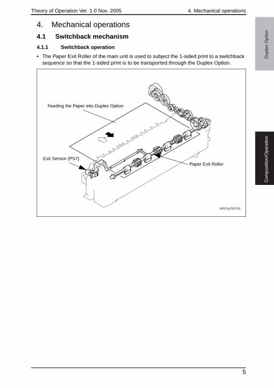
Theory of Operation Ver. 1.0 Nov. 2005 4. Mechanical operations
Co
mp
ositio
n/O
pe
ratio
nD
up
lex O
ptio
n
4. Mechanical operations
4.1 Switchback mechanism
4.1.1 Switchback operation
• The Paper Exit Roller of the main unit is used to subject the 1-sided print to a switchback sequence so that the 1-sided print is to be transported through the Duplex Option.
4057to2507c0
Exit Sensor (PS7)
Feeding the Paper into Duplex Option
Paper Exit Roller
5
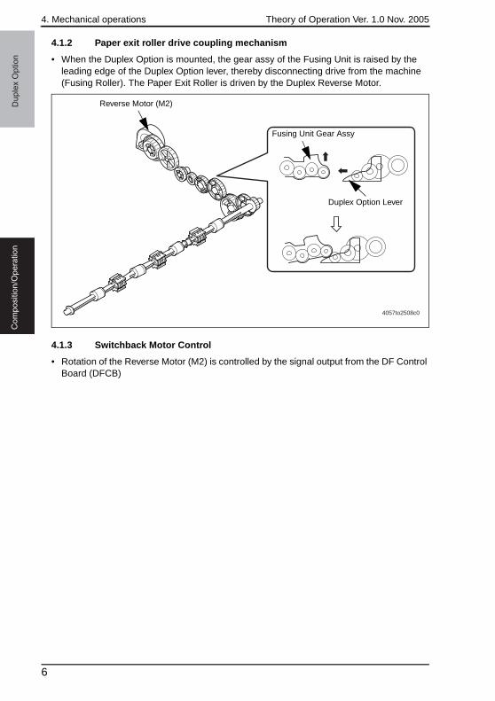
4. Mechanical operations Theory of Operation Ver. 1.0 Nov. 2005D
up
lex O
ptio
nC
om
po
sitio
n/O
pe
ratio
n
4.1.2 Paper exit roller drive coupling mechanism
• When the Duplex Option is mounted, the gear assy of the Fusing Unit is raised by the leading edge of the Duplex Option lever, thereby disconnecting drive from the machine (Fusing Roller). The Paper Exit Roller is driven by the Duplex Reverse Motor.
4.1.3 Switchback Motor Control
• Rotation of the Reverse Motor (M2) is controlled by the signal output from the DF Control Board (DFCB)
4057to2508c0
Reverse Motor (M2)
Duplex Option Lever
Fusing Unit Gear Assy
6
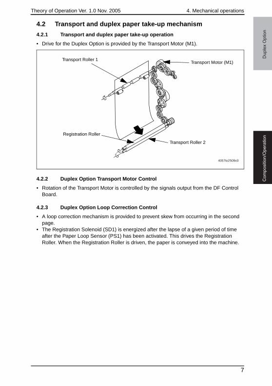
Theory of Operation Ver. 1.0 Nov. 2005 4. Mechanical operations
Co
mp
ositio
n/O
pe
ratio
nD
up
lex O
ptio
n
4.2 Transport and duplex paper take-up mechanism
4.2.1 Transport and duplex paper take-up operation
• Drive for the Duplex Option is provided by the Transport Motor (M1).
4.2.2 Duplex Option Transport Motor Control
• Rotation of the Transport Motor is controlled by the signals output from the DF Control Board.
4.2.3 Duplex Option Loop Correction Control
• A loop correction mechanism is provided to prevent skew from occurring in the second page.
• The Registration Solenoid (SD1) is energized after the lapse of a given period of time after the Paper Loop Sensor (PS1) has been activated. This drives the Registration Roller. When the Registration Roller is driven, the paper is conveyed into the machine.
4057to2509c0
Transport Motor (M1)Transport Roller 1
Transport Roller 2
Registration Roller
7
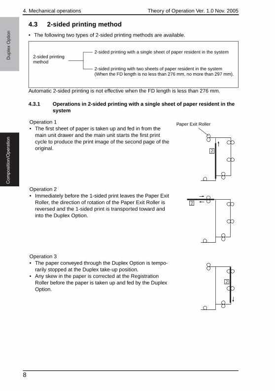
4. Mechanical operations Theory of Operation Ver. 1.0 Nov. 2005D
up
lex O
ptio
nC
om
po
sitio
n/O
pe
ratio
n
4.3 2-sided printing method
• The following two types of 2-sided printing methods are available.
Automatic 2-sided printing is not effective when the FD length is less than 276 mm.
4.3.1 Operations in 2-sided printing with a single sheet of paper resident in the system
2-sided printing method
2-sided printing with a single sheet of paper resident in the system
2-sided printing with two sheets of paper resident in the system (When the FD length is no less than 276 mm, no more than 297 mm).
2
Operation 1• The first sheet of paper is taken up and fed in from the
main unit drawer and the main unit starts the first print cycle to produce the print image of the second page of the original.
Paper Exit Roller
Operation 2• Immediately before the 1-sided print leaves the Paper Exit
Roller, the direction of rotation of the Paper Exit Roller is reversed and the 1-sided print is transported toward and into the Duplex Option.
2
Operation 3• The paper conveyed through the Duplex Option is tempo-
rarily stopped at the Duplex take-up position.• Any skew in the paper is corrected at the Registration
Roller before the paper is taken up and fed by the Duplex Option.
2
8
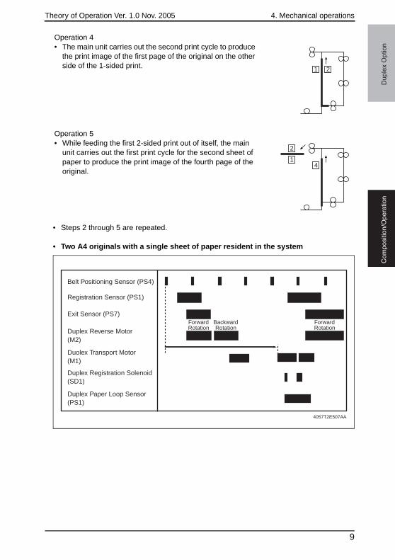
Theory of Operation Ver. 1.0 Nov. 2005 4. Mechanical operations
Co
mp
ositio
n/O
pe
ratio
nD
up
lex O
ptio
n
• Steps 2 through 5 are repeated.
• Two A4 originals with a single sheet of paper resident in the system
Operation 4• The main unit carries out the second print cycle to produce
the print image of the first page of the original on the other side of the 1-sided print. 1 2
Operation 5• While feeding the first 2-sided print out of itself, the main
unit carries out the first print cycle for the second sheet of paper to produce the print image of the fourth page of the original.
1
2
4
ForwardRotation
ForwardRotation
BackwardRotation
Duplex Registration Solenoid (SD1)
Duolex Transport Motor(M1)
Duplex Reverse Motor (M2)
Registration Sensor (PS1)
Exit Sensor (PS7)
Belt Positioning Sensor (PS4)
Duplex Paper Loop Sensor (PS1)
4057T2E507AA
9
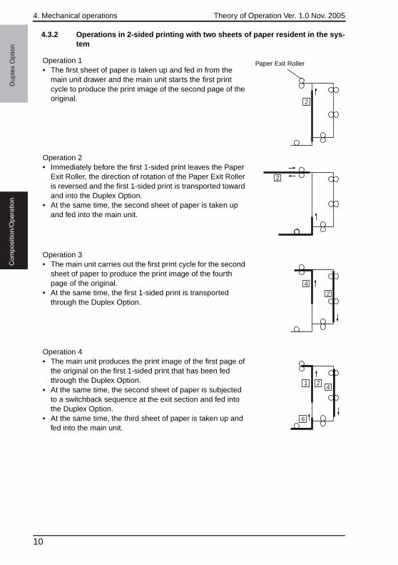
4. Mechanical operations Theory of Operation Ver. 1.0 Nov. 2005D
up
lex O
ptio
nC
om
po
sitio
n/O
pe
ratio
n
4.3.2 Operations in 2-sided printing with two sheets of paper resident in the sys-tem
2
Operation 1• The first sheet of paper is taken up and fed in from the
main unit drawer and the main unit starts the first print cycle to produce the print image of the second page of the original.
Paper Exit Roller
2
Operation 2• Immediately before the first 1-sided print leaves the Paper
Exit Roller, the direction of rotation of the Paper Exit Roller is reversed and the first 1-sided print is transported toward and into the Duplex Option.
• At the same time, the second sheet of paper is taken up and fed into the main unit.
4
2
Operation 3• The main unit carries out the first print cycle for the second
sheet of paper to produce the print image of the fourth page of the original.
• At the same time, the first 1-sided print is transported through the Duplex Option.
Operation 4• The main unit produces the print image of the first page of
the original on the first 1-sided print that has been fed through the Duplex Option.
• At the same time, the second sheet of paper is subjected to a switchback sequence at the exit section and fed into the Duplex Option.
• At the same time, the third sheet of paper is taken up and fed into the main unit.
1 2
6
4
10
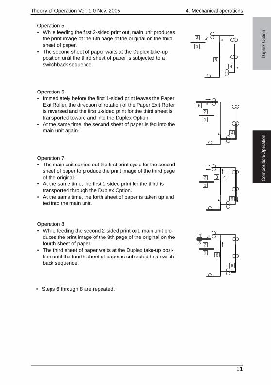
Theory of Operation Ver. 1.0 Nov. 2005 4. Mechanical operations
Co
mp
ositio
n/O
pe
ratio
nD
up
lex O
ptio
n
• Steps 6 through 8 are repeated.
Operation 5• While feeding the first 2-sided print out, main unit produces
the print image of the 6th page of the original on the third sheet of paper.
• The second sheet of paper waits at the Duplex take-up position until the third sheet of paper is subjected to a switchback sequence.
1
4
2
6
1
4
2
6
Operation 6• Immediately before the first 1-sided print leaves the Paper
Exit Roller, the direction of rotation of the Paper Exit Roller is reversed and the first 1-sided print for the third sheet is transported toward and into the Duplex Option.
• At the same time, the second sheet of paper is fed into the main unit again.
1
42
6
3
Operation 7• The main unit carries out the first print cycle for the second
sheet of paper to produce the print image of the third page of the original.
• At the same time, the first 1-sided print for the third is transported through the Duplex Option.
• At the same time, the forth sheet of paper is taken up and fed into the main unit.
1 8
23
4
6
Operation 8• While feeding the second 2-sided print out, main unit pro-
duces the print image of the 8th page of the original on the fourth sheet of paper.
• The third sheet of paper waits at the Duplex take-up posi-tion until the fourth sheet of paper is subjected to a switch-back sequence.
11
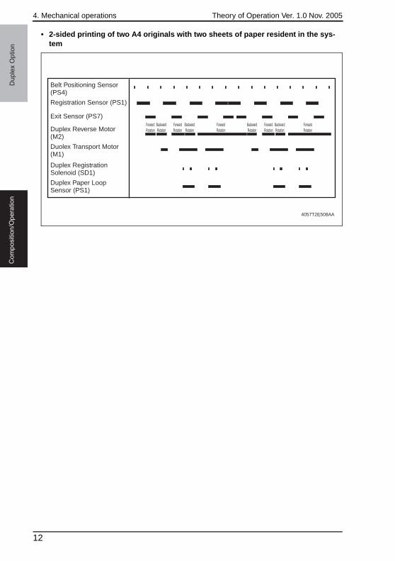
4. Mechanical operations Theory of Operation Ver. 1.0 Nov. 2005D
up
lex O
ptio
nC
om
po
sitio
n/O
pe
ratio
n
• 2-sided printing of two A4 originals with two sheets of paper resident in the sys-tem
4057T2E508AA
Belt Positioning Sensor (PS4)
Registration Sensor (PS1)
Exit Sensor (PS7)
Duplex Reverse Motor (M2)
Duolex Transport Motor (M1)
Duplex Registration Solenoid (SD1)
Duplex Paper Loop Sensor (PS1)
ForwardRotation
BackwardRotation
ForwardRotation
ForwardRotation
ForwardRotation
ForwardRotation
BackwardRotation
BackwardRotation
BackwardRotation
12

SERVICE MANUAL
2005.112005.11Ver. 1.0Ver. 1.0
2005.11 Ver.1.0
2005.11 Ver.1.0
© 2005 KONICA MINOLTA BUSINESS TECHNOLOGIES, INC.© 2005 KONICA MINOLTA BUSINESS TECHNOLOGIES, INC.
Printed in JapanPrinted in JapanDD4139CE1-XXXXDD4139CE1-XXXX
Use of this manual should be strictly supervised toavoid disclosure of confidential information.Use of this manual should be strictly supervised toavoid disclosure of confidential information.
magicolor 2480MF
mag
icolo
r 2480MF
THEORY OF OPERATION
THE
OR
Y O
F OP
ER
ATION