Embed Size (px)
Citation preview

Sept.2001 Shanghai symposiumD.T. Jiang
Acknowledgements
Deming Shu, APS
Tom Rebedeue, SSRL

Sept.2001 Shanghai symposiumD.T. Jiang
Canadian Light Source Front Ends
D.T. Jiang and E. Hallin, CLS, Saskatoon, Canada
Outline• Generic Specs of CLS Front Ends• Type of SR Sources• SR Thermal Power Loads• FE Layouts: Two-ID/Straight, One-ID/Straight, BM• SR Ray Tracing• Bremsstrahlung Ray Tracing• Current Design Issues• Summary

Sept.2001 Shanghai symposiumD.T. Jiang
CLS Top View

Sept.2001 Shanghai symposiumD.T. Jiang
45mm-U(SGM)
185mm-U (PGM)
75mm-EPU(SPM)
22mm-SGU(PX)
WSup33(Sup-conduct)
Period length (cm) 4.5 18.5 7.5 2.2 3.3
Device length (m) 1.189 1.760 1.60 1.610 1.221
Number of periods 26 9 21 74 37
Max. magnetic field B0(T) 0.843 0.751 0.747 0.912 1.917
Critical Ec (keV) - - - - 10.727
Max. deflection parameter, K 3.54 13.0 5.23 1.87 5.91
K/ (rad) (CLS 1/= 176 rad) 623 2291 922 330 1040
Total Power (kW) 2.21 2.51 2.34 3.60 11.95
Peak Power (kW/mrad2) 8.4 2.6 6.0 25.3 27.2
ID-photon shutter distance (m) 10.94 8.785 10.00 8.21* 10.00
Peak heat flux @ shutter (W/mm2) 70 34 60 484 272
Summary of Design Parameters for CLS Insertion Devices

Sept.2001 Shanghai symposiumD.T. Jiang
Superconducting Wiggler Brilliance
1016
2
3
4
567
1017
Phot
/s/0
.1%
bw/m
m2 /m
r2
100 eV2 3 4 5 6 7 8
1keV2 3 4 5 6 7 8
10keV2 3 4 5 6 7 8
100keVPhoton Energy
Period = 33 mm, B = 1.9 T, K = 5.91,
Length ~1.2 m

Sept.2001 Shanghai symposiumD.T. Jiang
Superconduction WigglerHeat Flux at the 1st FE Fixed Mask
-3
-2
-1
0
1
2
3
mm
-10 -5 0 5 10mm
530 510 490 470 450
430
410 390
370 350 330
310 290 270
250
230
210 190
170 150
130
110
90
70
50
30 10
Sept.2001 Shanghai symposiumD.T. Jiang
SGU Heat Flux Density Map @ FM-1
-2
-1
0
1
2
mm
3210-1-2-3mm
650
630 610 590 550
530 510
490
470
450
430
410 390 370
350 330 310
290
270
250
230
210 190
170 150
130
110
90 70
50
30 10
Max heat flux density 702 W/mm2
This is calculated for a second CLS Small Gap Undulator at thedown stream location in a chicaned Two-SGU/Straight.

Sept.2001 Shanghai symposiumD.T. Jiang
Thermal Power Loads
CLS IDsPtotal
(kW)W/mm2
@FM1W/mm2
@FM2W/mm2
@PSH-1W/mm2
@FM3W/mm2
@PSH-2W/mm2
@FM4
33mm1.9T Wiggler (XAFS)
11.73 536 345 - - 273 162
22mm-SGU (PX)
3.60 702 593 466 350 270 176
45mm-U(SGM)
&185mm-U
(PGM)
4.72 213 136 - - 108 64
75mm-EPU x 2 4.68 258 162 - - 127 74
BM10.070 /H-
mrad29 14 12 6 6 -

Sept.2001 Shanghai symposiumD.T. Jiang
Reference APS FE Specifications 1) APS Undulator A @ 1st fixed mask Ptotal = 6.0 kW, Pdensity=559
W/mm2 . D. Shu et. al. Nucl. Instrum. & Methods, A 347, 584-590(1994)
2) APS FE V1.2 would accommodate the total power (>~6 kW)
and power density load of 600 W/mm2. D. Shu et. al. (preprint)
3) In APS FE V1.5, Ptotal = 9 kW and Pdensity=800 W/mm2, a design
targeting at thermal load capacity of 12 kW total power with 1.2 kW/mm2 maximum power density (4.8-meter-long double undulator A with APS operating at 100 mA).
D. Shu et. al. (unpublished)

Sept.2001 Shanghai symposiumD.T. Jiang
Schematic of CLS Two-ID/Straight FE
Sept.2001 Shanghai symposiumD.T. Jiang
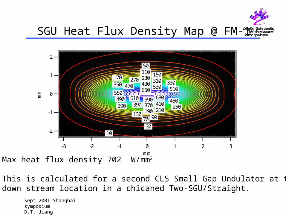
Layout of CLS Two-ID/Straight FE: plan view

Sept.2001 Shanghai symposiumD.T. Jiang
Layout of CLS Two-ID/Straight FE: side view

Sept.2001 Shanghai symposiumD.T. Jiang
FE Angular throughput required for phase I CLS beamlines
FE Identifier Source/BL IdentifierVertical (mrad)
Horizontal (mrad)
Duplex ID FE (11ID) 185mm-U (11ID.2, VLS PGM) 0.7 0.7
45mm-U (11ID.1, SGM) 0.140 0.360
Duplex ID FE (10ID)
75mm-EPU (10ID.1 Spectromicroscopy)
0.20 0.20
75mm-EPU (10ID.2, NOT TO BE IMPLEMENTED INNITIALLY)
Assumed same as above
Assumed same as above
Single ID FE(08ID)
22mm-SGU (08ID.1, Protein crystallgraphy)
0.060 0.120
Sing ID FE(07ID)
35mm-Wiggler (XAFS) 0.24 1.60
BM FE (BM1)BM1
0.6 2.0
Sept.2001 Shanghai symposiumD.T. Jiang
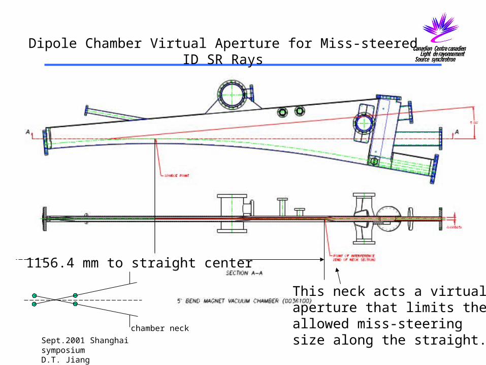
Dipole Chamber Virtual Aperture for Miss-steered ID SR Rays
This neck acts a virtualaperture that limits theallowed miss-steeringsize along the straight.
1156.4 mm to straight center
chamber neck

Sept.2001 Shanghai symposiumD.T. Jiang
SR Ray Tracing of Two-ID/Straight FE: vertical
Sept.2001 Shanghai symposiumD.T. Jiang

Sept.2001 Shanghai symposiumD.T. Jiang
SR Ray Tracing of Two-ID/Straight FE: horizontal
Example:SGM/PGMSector

Sept.2001 Shanghai symposiumD.T. Jiang
SR Horizontal trace detail

Sept.2001 Shanghai symposiumD.T. Jiang
Bremsstrahlung Ray Tracing for Two-ID/Straight FE: vertical
1st Collimator thickness determined by EGS4 calculation.

Sept.2001 Shanghai symposiumD.T. Jiang
Bremsstrahlung Ray Tracing for Two-ID/Straight FE:horizontal

Sept.2001 Shanghai symposiumD.T. Jiang
Layout of Single ID/Straight FE: plan view

Sept.2001 Shanghai symposiumD.T. Jiang
Layout of Single ID/Straight FE: side view

Sept.2001 Shanghai symposiumD.T. Jiang
Shutter:moving box-type mask (D.Shu et al,APS)

Sept.2001 Shanghai symposiumD.T. Jiang
Bending Magnet FE (BM1): plan view
Sept.2001 Shanghai symposiumD.T. Jiang
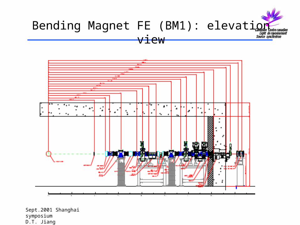
Bending Magnet FE (BM1): elevation view
Sept.2001 Shanghai symposiumD.T. Jiang
Status of CLS BL FE Construction
•Conceptual Designs are completed. The designs are compact, simpler and with the same thermal power load capacity compared to the template APS FE design. •Detail engineering design is in progress (mainly FEA Analysis confirmation for the results Extrapolated from the parametric studies of the APS FE designs).
•Tendering process is scheduled to start by the end of 2001.


![The Canton advocate (Canton, D.T. [S.D.]). (Canton, D.T](https://img.pdfslide.us/doc/110x75/627da8d50d94944094392a89/the-canton-advocate-canton-dt-sd-canton-dt-.jpg)