Embed Size (px)
Citation preview
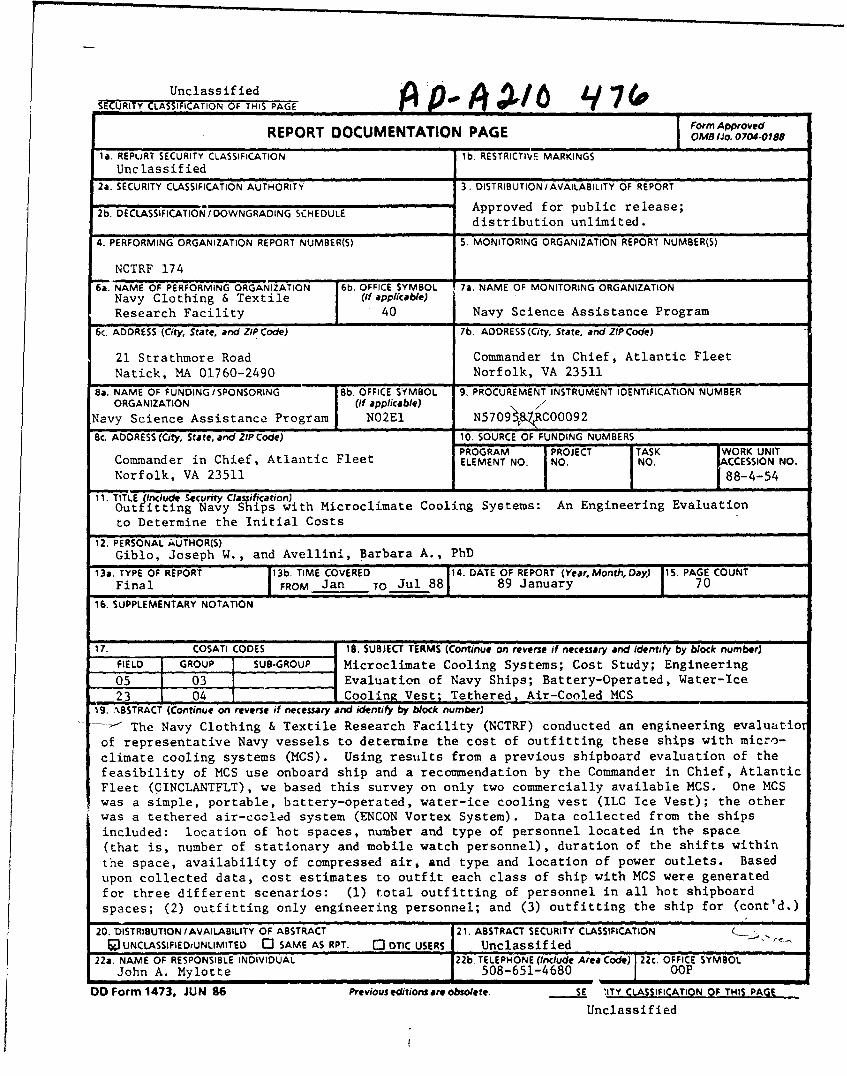
UnclassifiedSECURITY CLASSIFICATION OF THIS PAGE , A
Form Approved
REPORT DOCUMENTATION PAGE OMr fo.o0o0rOv
la. REPURT SECURITY CLASSIFICATION lb. RESTRICTIVE MARKINGS
Unclassified
2a. SECURITY CLASSIFICATION AUTHORITY 3. DISTRIBUTION /AVAILABILITY OF REPORT
2b. DECLASSIFICATION /DOWNGRADING SCHEDULE Approved for public release;distribution unlimited.
4. PERFORMING ORGANIZATION REPORT NUMBER(S) 5. MONITORING ORGANIZATION REPORT NUMBER(S)
NCTRF 174
6a. NAME OF PERFORMING ORGANIZATION 6b. OFFICE SYMBOL 7a. NAME OF MONITORING ORGANIZATIONNavy Clothing & Textile (If applicable)Research Facility 40 Navy Science Assistance Program
6c. ADDRESS (City, State. and ZIP Code) 7b. ADDRESS (City, State, and ZIP Code)
21 Strathmore Road Commander in Chief, Atlantic FleetNatick, MA 01760-2490 Norfolk, VA 23511
8a. NAME OF FUNDING/SPONSORING 8b. OFFICE SYMBOL 9. PROCUREMENT INSTRUMENT IDENTIFICATION NUMBERORGANIZATION (if applicable)\/C0
Navy Science Assistance Program N02EI N57098&RCO0092
8c. ADDRESS (City, State, and ZIP Code) 10. SOURCE OF FUNDING NUMBERS
PROGRAM PROJECT TASK WORK UNITCommander in Chief, Atlantic Fleet ELEMENT NO. NO. NO. ACCESSION NO.Norfolk, VA 23511 88-4-54
11. TITLEInclude Security Classification) I t,
Outfitting Navy Ships with Microclimate Cooling Systems: An Engineering Evaluation
to Determine the Initial Costs
12. PERSONAL AUTHOR(S)Giblo, Joseph W., and Avellini, Barbara A., PhD
13a. TYPE OF REPORT 13b. TIME COVERED 14. DATE OF REPORT (Year, Month, Day) 15. PAGE COUNTFinal FROM Jan TO Jul 88 89 January 70
16. SUPPLEMENTARY NOTATION
17. COSATI CODES i8. SUBJECT TERMS (Continue on reverse if necessary and identify by block number)FIELD GROUP SUB-GROUP Microclimate Cooling Systems; Cost Study; Engineering
05 03 Evaluation of Navy Ships; Battery-Operated, Water-Icek23 04 Cooling Vest; Tethered, Air-Cooled MCS,
'9. ABSTRACT (Continue on reverse if necessary and identify by block number r
-- The Navy Clothing & Textile Research Facility (NCTRF) conducted an engineering eva]uatior
of representative Navy vessels to determine the cost of outfitting these ships with micro-
climate cooling systems (MCS). Using results from a previous shipboard evaluation of the
feasibility of MCS use onboard ship and a recommendation by the Commander in Chief, AtlanticFleet (PINCLANTFLT), we based this survey on only two commercially available MCS. One MCSwas a simple, portable, battery-operated, water-ice cooling vest (ILC Ice Vest); the otherwas a tethered air-cooled system (ENCON Vortex System). Data collected from the ships
included: location of hot spaces, number and type of personnel located in the space
(that is, number of stationary and mobile watch personnel), duration of the shifts within
the space, availability of compressed air, and type and location of power outlets. Basedupon collected data, cost estimates to outfit each class of ship with MCS were generated
for three different scenarios: (1) total outfitting of personnel in all hot shipboard
spaces; (2) outfitting only engineering personnel; and (3) outfitting the ship for (cont'd.)
20. DISTRIBUTION/AVAILABILITY OF ABSTRACT 21. ABSTRACT SECURITY CLASSIFICATIONOUNCLASSIFIEDiUNLIMITED C3 SAME AS RPT. 0 DTIC USERS Unclassified
22a. NAME OF RESPONSIBLE INDIVIDUAL 22b, TELEPHONE (Include Area Code) 22c. OFFICE SYMBOLJohn A. Mylotte 508-651-4680 OOP
DO Form 1473, JUN 86 Previous editions are obsolete. SE 'ITY CLASSIFICATIQN OF THIS PAGE
Unclassified
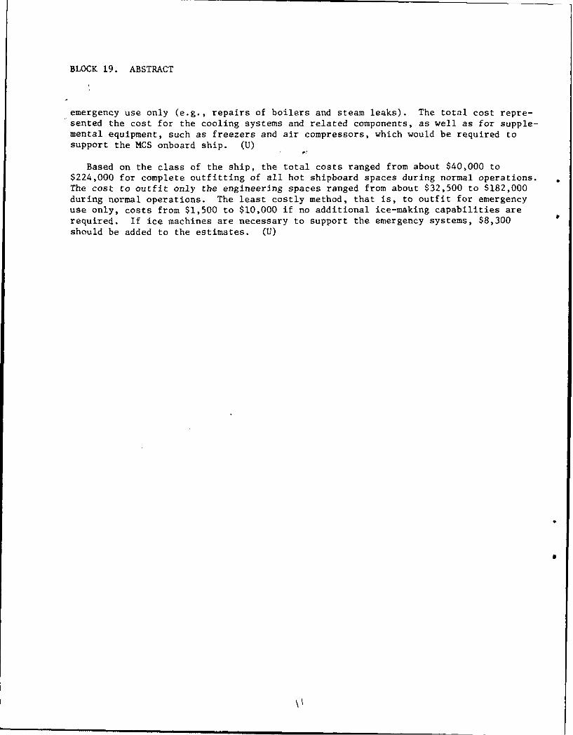
BLOCK 19. ABSTRACT
emergency use only (e.g., repairs of boilers and steam leaks). The total cost repre-sented the cost for the cooling systems and related components, as well as for supple-mental equipment, such as freezers and air compressors, which would be required tosupport the MCS onboard ship. (U)
Based on the class of the ship, the total costs ranged from about $40,000 to$224,000 for complete outfitting of all hot shipboard spaces during normal operations.The cost to outfit only the engineering spaces ranged from about $32,500 to $182,000during normal operations. The least costly method, that is, to outfit for emergencyuse only, costs from $1,500 to $10,000 if no additional ice-making capabilities arerequired. If ice machines are necessary to support the emergency systems, $8,300
should be added to the estimates. (U)
. . . . m ~ , mum m i u| nnnu mnmnununav1 1 llr ...

TABLE OF CONTENTS
PAGE
List of Illustrations iv
List of Tables vi
Introduction i
Background 2
Description of Cooling Systems 4
Methods 5
Results 6
Discussion 12
References 19
Illustrations 20
Tables 42
Accession For
NTIS GRA&IDTIO TABUnanounced 0
Justifleatlo-
By
Distribution/
Availability CodesAvail and/or
Dist Speolal
iii
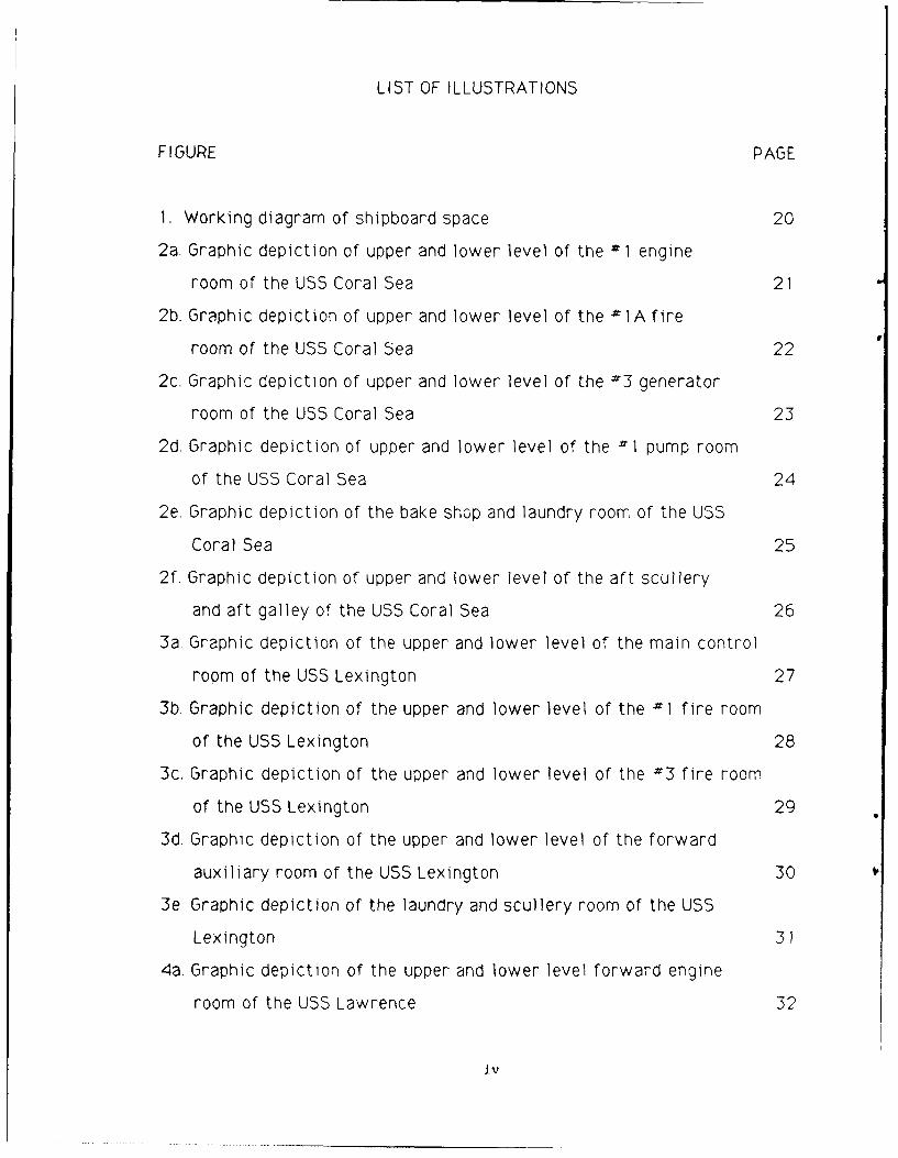
LIST OF ILLUSTRATIONS
F I GURE PAGE
1. Working diagram of shipboard space 20
2a. Graphic depiction of upper and lower level of the -1 engine
room of the USS Coral Sea 21
2b. Graphic depiction of upper and lower level of the -'1 A fire
room of the USS Coral Sea 22
2c. Graphic depiction of upper and lower level of the #3 generator
room of the USS Coral Sea 23
2d. Graphic depiction of upper and lower level of the I pump room
of the USS Coral Sea 24
2e. Graphic depiction of the bake shop and laundry room of the USS
Coral Sea 25
2f. Graphic depiction of upper and lower level of the aft scullery
and aft galley of the USS Coral Sea 26
3a. Graphic depiction of the upper and lower level of the main control
room of the USS Lexington 27
3b. Graphic depiction of the upper and lower level of the #1 fire room
of the USS Lexington 28
3c. Graphic depiction of the upper and lower level of the #3 fire room
of the USS Lexington 29
3d. Graphic depiction of the upper and lower level of the forward
auxiliary room of the USS Lexington 30
3e. Graphic depiction of the laundry and scullery room of the USS
Lexington 31
4a. Graphic depiction of the upper and lower level forward engine
room of the USS Lawrence 32
iv
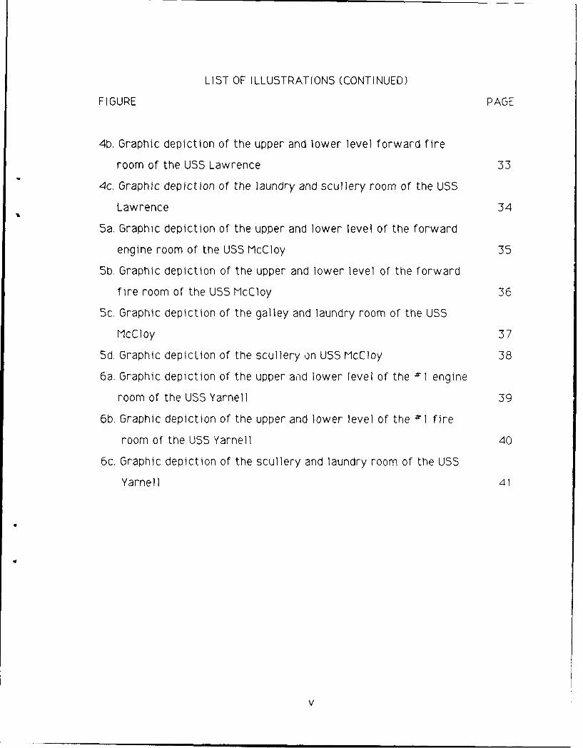
LIST OF ILLUSTRATIONS (CONTINUED)
F I GURE PAGE
4b. Graphic depiction of the upper and lower level forward fire
room of the USS Lawrence 33
4c. Graphic depiction of the laundry and scullery room of the USS
Lawrence 34
5a. Graphic depiction of the upper and lower level of the forward
engine room of the USS McCloy 35
5b. Graphic depiction of the upper and lower level of the forward
fire room of the USS McCloy 36
5c. Graphic depiction of the galley and laundry room of the USS
McCloy 37
5d. Graphic depiction of the scullery on USS McCloy 38
6a. Graphic depiction of the upper and lower level of the -I engine
room of the USS Yarnell 39
6b. Graphic depiction of the upper and lower level of the #1 fire
room of the USS Yarnell 40
6c. Graphic depiction of the scullery and laundry room of the USS
Yarnell 41
V
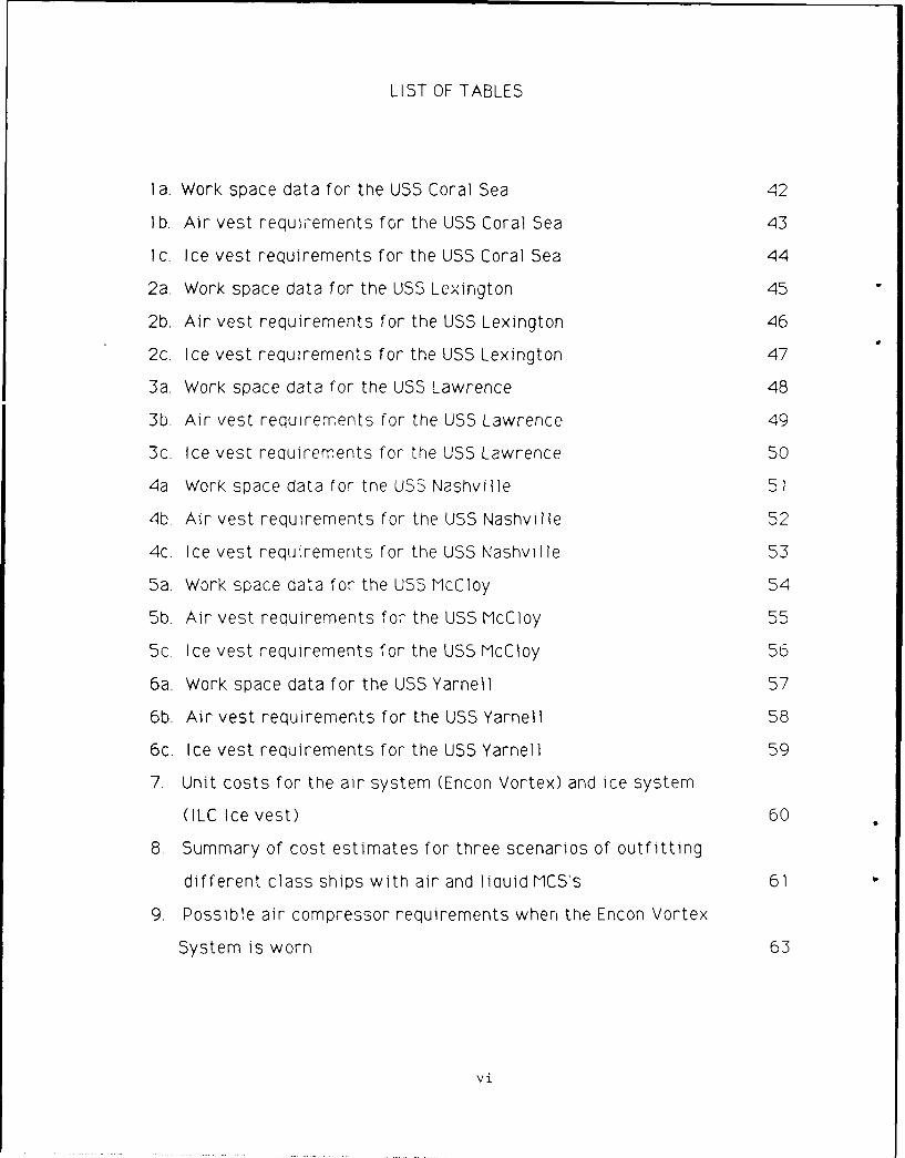
LIST OF TABLES
1 a. Work space data for the USS Coral Sea 42
I b. Air vest requiements for the USS Coral Sea 43
I c. Ice vest requirements for the USS Coral Sea 44
2a. Work space data for the USS Lexington 45
2b. Air vest requirements for the USS Lexington 46
2c. Ice vest requirements for the USS Lexington 47
3a. Work space data for the USS Lawrence 48
3b. Air vest requirements for the USS Lawrence 49
3c. Ice vest requirements for the USS Lawrence 50
4a Work space data for tne USS Nashville 51
4b. Air vest requirements for the USS Nashville 52
4c. Ice vest requirements for the USS Nashville 53
5a. Work space data for the USS McCloy 54
5b. Air vest requirements for the USS McCloy 55
5c. Ice vest requirements for the USS McCloy 56
6a. Work space data for the USS Yarnell 57
6b. Air vest requirements for the USS Yarnell 58
6c. Ice vest requirements for the USS Yarnell 59
7. Unit costs for the air system (Encon Vortex) and ice system
(ILC Ice vest) 60
8. Summary of cost estimates for three scenarios of outfitting
different class ships with air and liquid MCS's 61
9. Possible air compressor requirements when the Encon Vortex
System is worn 63
vi
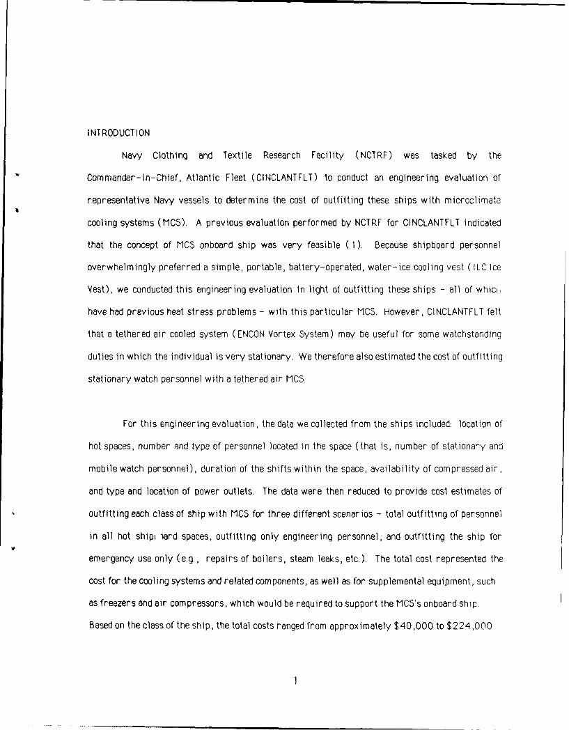
INTRODUCTION
Navy Clothing and Textile Research Facility (NCTRF) was tasked by the
Commander-in-Chief, Atlantic Fleet (CINCLANTFLT) to conduct an engineering evaluation of
representative Navy vessels to determine the cost of outfitting these ships with microclimate
cooling systems (MCS). A previous evaluation performed by NCTRF for CINCLANTFLT indicated
that the concept of MCS onboard ship was very feasible (1). Because shipboard personnel
overwhelmingly preferred a simple, portable, battery-operated, water-ice cooling vest ( ILC Ice
Vest), we conducted this engineering evaluation in light of outfitting these ships - all of whici,
have had previous heat stress problems - with this particular MCS. However, CINCLANTFLT felt
that a tethered air cooled system (ENCON Vortex System) may be useful for some watchstarding
duties in which the individual is very stationary. We therefore also estimated the cost of outfitting
stationary watch personnel with a tethered air MCS.
For this engineering evaluation, the data we collected from the ships included: location of
hot spaces, number and type of personnel located in the space (that is, number of stationary and
mobile watch personnel), duration of the shifts within the space, availability of compressed air,
and type and location of power outlets. The data were then reduced to provide cost estimates of
outfitting each class of ship with MCS for three different scenarios - total outfitting of personnel
in all hot shipi iard spaces, outfitting only engineering personnel, and outfitting the ship for
emergency use only (e.g., repairs of boilers, steam leaks, etc.). The total cost represented the
cost for the cooling systems and related components, as well as for supplemental equipment, such
as freezers and air compressors, which would be required to support the MCS's onboard ship.
Based on the class of the ship, the total costs ranged from approximately $40,000 to $224,000
for complete outfitting of all hot shipboard spaces during normal operations. The cost to outfit
only the engineering spaces ranged from approximately $32,500 to $182,000. The least-costly
method - that is, to outfit for emergency use only - costs between $1 500 to $10,000 if no
additional ice source is needed.
This report provides some background as to the use of MCS onboard ship and details the
methodology and results of the shipboard survey. Recommendations for utilization of the cooling
systems onboard ship are also included.
BACKGROUND
Heat stress is a severe problem on older, steam-driven vessels and is responsible for
limiting work times, reducing work performance, and jeopardizing personnel safety. One
method of alleviating heat stress is through the use of personal cooling systems which condition
the environment in immediate contact witn the individual. To investigate the feasibility of using
microclimate cooling systems onboard ship, CINCLANTFLT tasked NCTRF to conduct an evaluation
on hot-designated Navy ships. The study was intended as a subjective and objective evaluation of
the concept of using MCS to relieve heat stress, increase work times, and improve personnel
morale in engine spaces and in other hot spots aboard the ship.
Two cooling concepts, air and liquid, were evaluated aboard the USS Lexington in
March-April 1987 ( 1 ). Data gathered during this study included physiological measurements,
performance assessment, and subjective comments gathered through questionnaires and verbal
debriefings. We also evaluated the extent of logistic support required to maintain the cooling
systems. The main conclusion of the evaluation indicated that MCS was strongly favored, with
the portable, battery-operated water-ice vest (ILC Ice Vest) the preferred system. The air
concept ( Encon Vortex), although extremely effective and low-cost, was not well-received The
overwhelming complaint for the air vortex system was the need to be tethered to a compressed
air line. (There are no suitable commercially available portable air systems.) The sailors did
not like the limitation on mobility imposed by the tethered cord, and even individuals who were
quite stationary on their watch did not prefer the air vest concept.
Based on the results of the shipboard study of MCS and laboratory evaluations that
demonstrated the effectiveness of MCS's in reducing heat stress (2,3), CINCLANTFLT wanted to
determine the cost of outfitting representative Navy vessels with MCS's. Even though the
tethered air system was not favorably received, CINCLANTFLT felt that it may be uscful for some
shipboard applications. The system is effective, low-cost, provides excellent cooling and, after
the initial setup, requires little logistic support. This system should be quite rugged for
individuals who are stationary. A better method for handling the tether cord may make the
system much more attractive to shipboard personnel.
A survey was conducted by CINCLANTFLT to identify which ships, and which spaces
onboard these ships, have a significant heat stress problem.
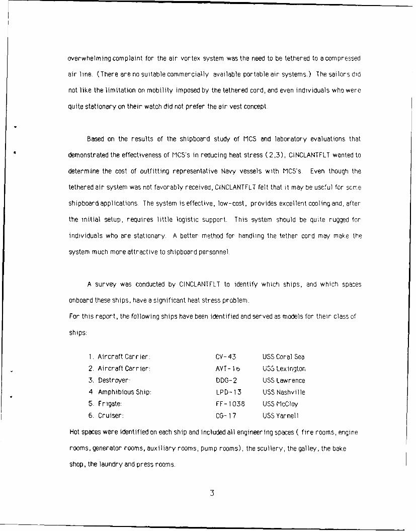
For this report, the following ships have been identified and served as models for their class of
ships:
I. Aircraft Carrier: CV-43 USS Coral Sea
2. Aircraft Carrier: AVT- 16 USS Lexington
3. Destroyer: DDG-2 USS Lawrence
4 Amphibious Ship: LPD- 13 USS Nashville
5. Frigate: FF- 1038 USS McCloy
6. Cruiser: CG- 17 USS Yarnell
Hot spaces were identified on each ship and included all engineering spaces ( fire rooms, engine
rooms, generator rooms, auxiliary rooms, pump rooms), the scullery, the galley, the bake
shop, the laundry and press rooms.
3
Tiiere are several approaches to outfitting ships with MCS. The most comprehensive and
most expensive approach is to outfit each person working in each hot space with his/her own
MCS. The second approach would be to outfit only engineering space personnel with MCS The
third and least comprehensii e approach is to provide each ship, based upon class, with a fixed
number of MCS, for emergency repair work in hot spaces. For this report, we generated data to
support each of these three possible scenarios under two possible conditions Normal Operations
and General Quarters A spectrum of cost estimates, depending upon each ship's unique needs
and/or wants, could therefore be generated
DESCRIPTION OF COOLING SYSTEMS
The two cooling systems considered in this evaluation are commercially available One is
a portable circulating liquid system and the other a tethered air circulating system The Model
1905 Cool Vest is manufactured by ILC Dover, Inc , of Frederica, DE It includes a torso vest
made of heat-sealed, polyurethane-coated nylon with an inner bladder that allows liquid to flow
through Its backpack contains an 8-volt, rechargeabie gel-cell battery (which lasts two hours
under normal usage) and pump/motor assembly. The backpack also contains a resealable plastic
bag which is filled with water (the circulating liquid) and ice (the cooling medium) The
manufacturer recommends 4-8 pounds of ice. In our shipboard evaluation, we used6 lbs of ise
so that replenishment was needed only every 2 hours We therefore based our cost estimate on
this utilization rate The total weight of the system with 6 lbs of ice was 13.5 pounds
The Encon Air Vortex System, Model 02-6360, consists of an air vest connected to a
vortex tube It is manufactured by Encon Corporation, Houston, TX The vest comes in two
sizes, regular and ext d large, and is constructed of a Buna-N-coated nylon shell with a
perforated interior and an inner air distribution system for both the front and rear of the vl,
High pressure air enters a vortex to be separated The cold air frnm the vortex tube is fel riln
4
the vest, while the warm air is directed away from the user. The temperature and flow rate of
the air into the vest can be controlled using the control valve located on the vortex tube. The
system is powered by a compressed air line. The manufacturer recommends anywhere from
80- 100 psig @ 20 scfm.
METHODS
The original representative list of ships identified in the BACKGROUND was followed.
With the exception of the USS Nashville, we personally visited the ships to gather and/or verify
information. Data from the USS Nashville were obtained from a previous study conducted by Life
Support Systems, Inc.( 4).
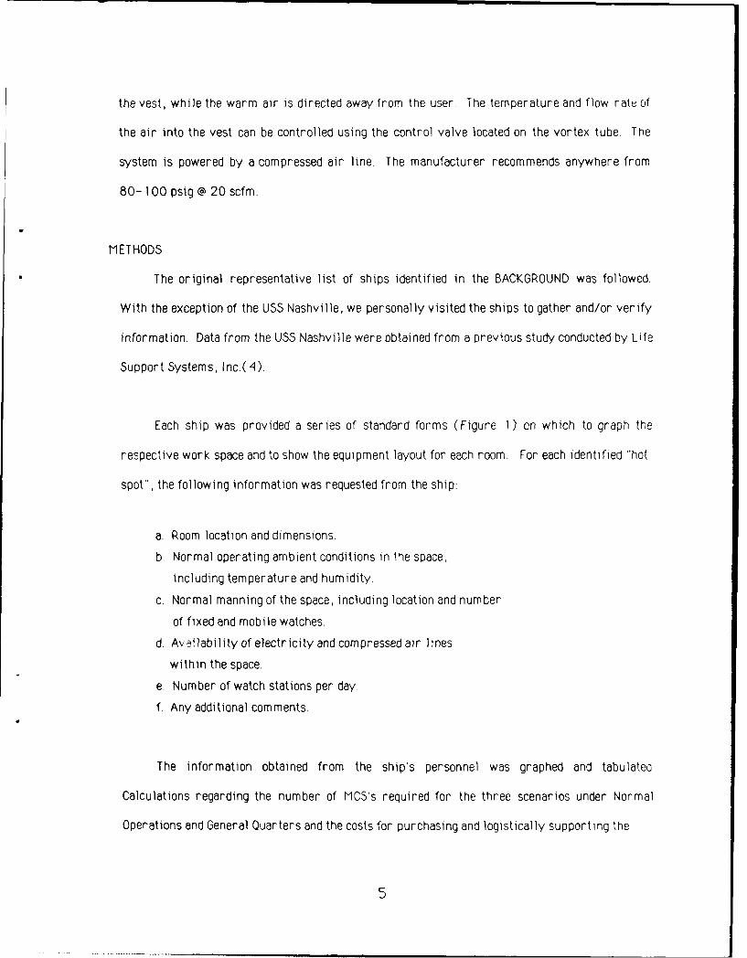
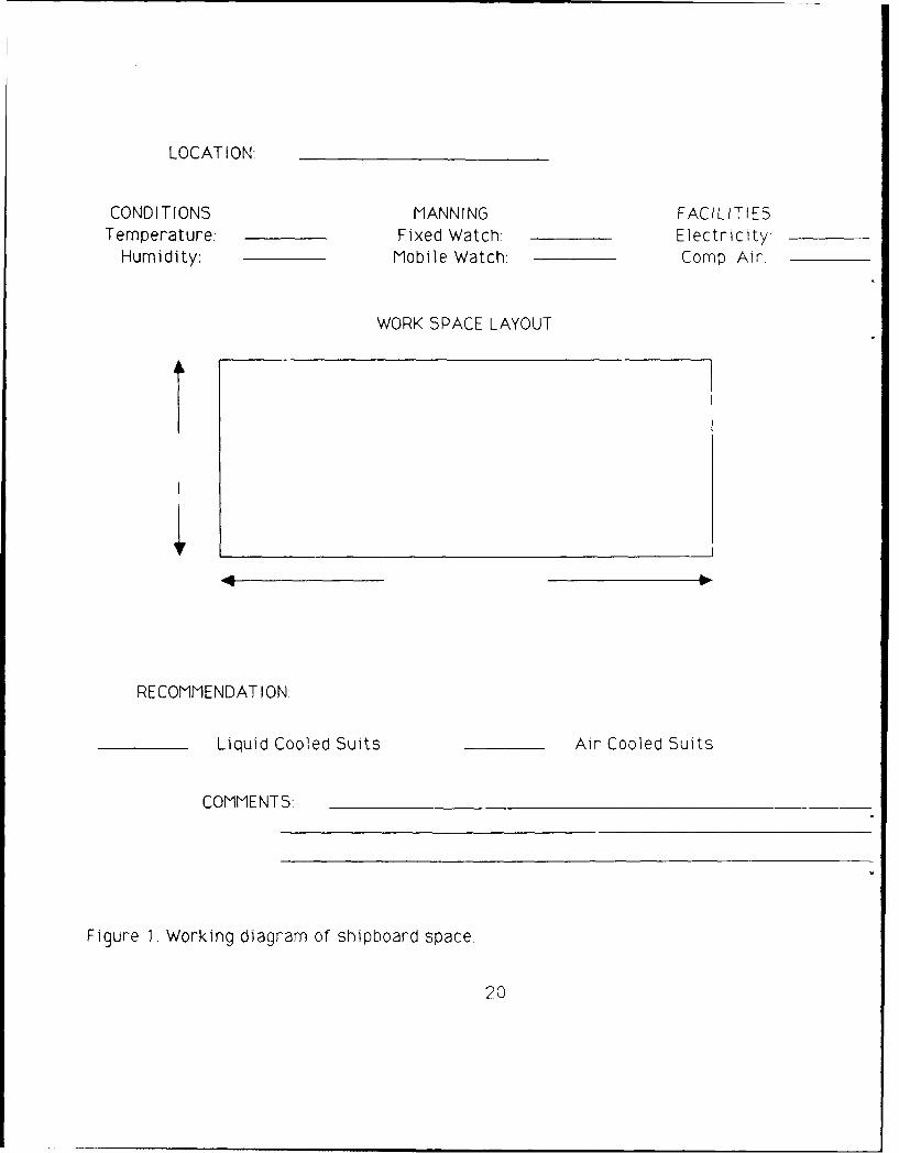
Each ship was provided a series of standard forms (Figure I) on which to graph the
respective work space and to show the equipment layout for each room. For each identified "hot
spot", the following information was requested from the ship:
a. Room location and dimensions.
b. Normal operating ambient conditions in tie space,
including temperature and humidity.
c. Normal manning of the space, including location and number
of fixed and mobile watches.
d. A'ailability of electricity and compressed air lines
within the space.
e. Number of watch stations per day
f. Any additional comments.
The information obtained from the ship's personnel was graphed and tabulateo
Calculations regarding the number of MCS's required for the three scenarios under Normal
Operations and General Quarters and the costs for purchasing and logistically supporting the
5
cooling systems were then made. (Normal operations are the normal every day manning
requirements. General Quarters are the emergency or alert operating conditions when manning
in the engineering spaces increase.)
The total number of required systems was determined through evaluation of the graphical
depiction of the spaces returned to us by the ships and verified by personal visits. Each
stationary (fixed) watchstander was issued an air vest; each mobile watchstander was issued a
portable ice vest. Except for emergency use only, all scenarios assumed that each watchstander
was issued his/her own MCS. This was the result of discussions with CINCLANTFLT and shl.s'
personnel who were concerned about cleanliness and hygiene of MCS that were shareo among
individuals.
Support equipment for the Encon Air Vest included regulators and filters, which could
support up to three vests at a time. For the ice vest, battery/charger systems were necessary to
operate the vest. The RESULTS section details the rationale for what comprised a system for
different classes of ships. In addition, because we were advised that available free2er capacity
onboard ship is limited, we estimated the number of ice machines required to support the total
number of portable ice vests for each ship. The costs for outfitting the ship for the three
scenarios was determined by multiplying the unit cost for each component by the total number of
required components.
RESULTS
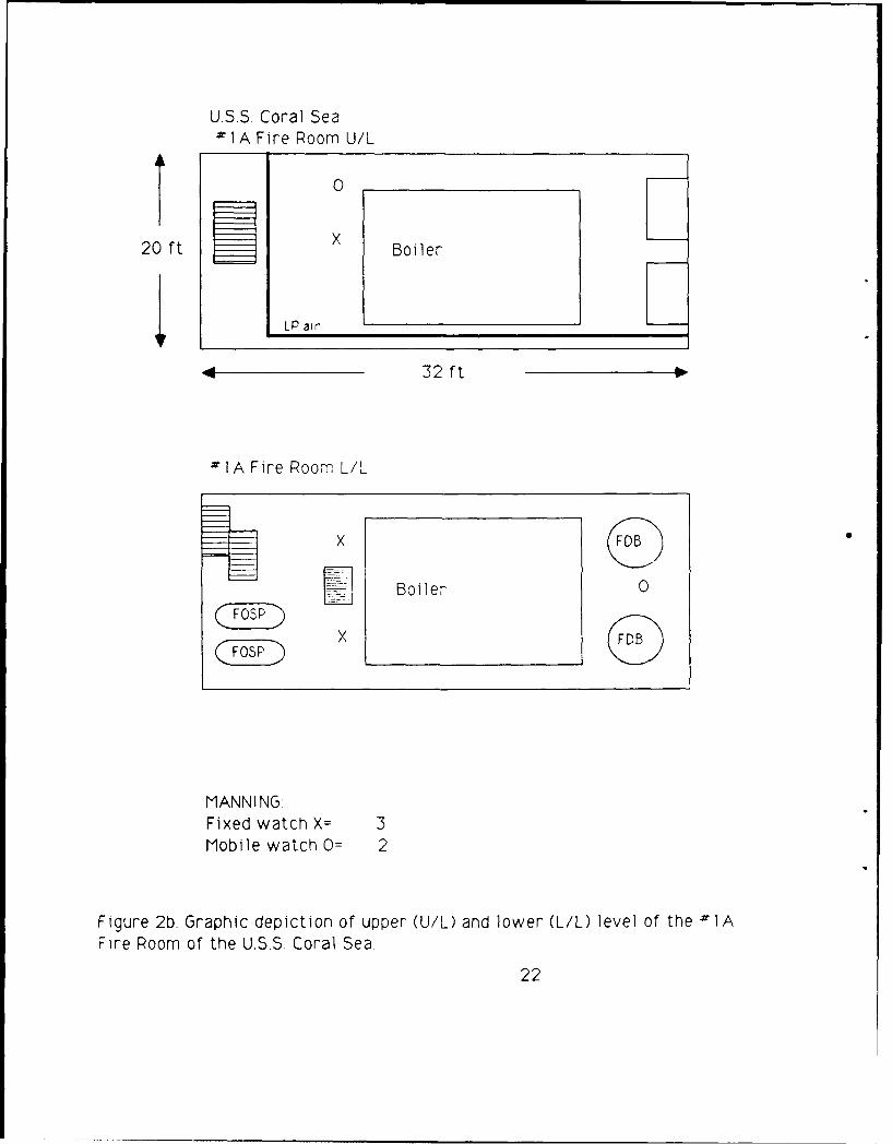
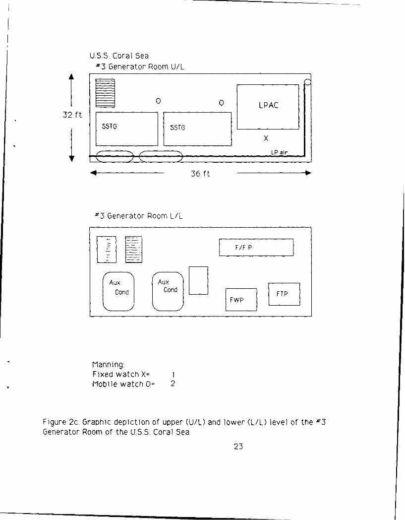
Figures 2 through 6 depict representative hot spaces from the classes of ships outlined in
the BACKGROUND. (As data from the USS Nashville were previously presented (4), no graphics
are provided for this ship.) The location of the ship's personnel (fixed or mobile) and maior
equipment are plotted in graphic form. The low-pressure compressed-air availability is
6

indicated as "LP Air". The location of the 440 YAC in or around the hot spaces could not be shown
on the graphs because of its location outside the immediate work space. Because of the
similarity of spaces, not all identified hot spaces were graphed. For example the USS Coral Sea
provided graphics for Engine Room -1 only, implying that Engine Rooms 2,3, and 4 are
arranged and manned in a similar fashion. Only Fire Room IA was graphed, implying that the 11
other fire rooms are similar. Unique spaces - such as the bake shop, laundry, scullery and
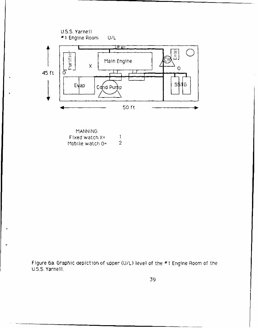
galley -were all individually graphed. We were not able to represent the lower level of the
engine room of the USS Yarnell because the ship was being refurbished at the time of our visit
and our ship's contact felt that, since there was no manning in the lower level, the graphics of
the upper level would suffice.
Tables 1 through 6 present the tabulated data for each ship. The hot spaces were
separated into engineering and other spaces. For each ship, three separate tables are presented
- one for a general description of the space, one for the air vest requirements, and one for the
ice vest requirements. Part A of the Tables describes the environmental conditions within the
space and the availability of electricity and 100 psi air supply. We were not able to get
information concerning the specific capacity size of each ship's air compressor. As described by
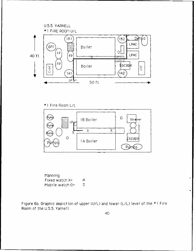
USS Yarnell personnel and noted in Table 6a, air supply may be prioritized under emergency
situations in which the air system would be shunted to operating engineering controls only.
Part B in the Tables represents tabulated data for the fixed watch air vest requirements
and cost. "Fixed Watch" refers to the number of personnel requiring a stationary system in the
work space. "Shifts" refers to the number of rotations of workers manning a watch station.
Normally, there are two or three shifts per work space. A two-shift watch station mans the
work space in two, twelve-hour or four, six-hour shifts. For the six-hour watches,
watchstanders return to duty every 1 2 hours. A three-shift work station mans the work soace
7
in three, eight-hour or six, four-hour shifts. For the four-hour watches, workers return to
their watch station every 12 hours. Therefore, for a two-shift watch station, only two groups
of workers stand watch throughout the day; for the three-shift stations, three groups are rotated
over 24 hours. The number of "Air Vests & Hoses" for any hot space is calculated as the product
of "Fixed Watch" x "Shifts". The summation of these numbers for all hot spaces provides the
total number of air vests needed to outfit all stationary personnel. Regulators and filters are
provided to support no more than three air vests at one time. Therefore, the required number of
"Regulators and Filters" for each space would equal the "Fixed Watch" divided by 3 and rounded
up to the next higher number.
Using unit cost values from Table 7, total cost estimates have been determined for both
Normal and General Quarters (GO) operations for Engineering, Other (non-engineering) spaces,
and Complete Outfitting. For outfitting during normal operations, the total number of required
vests and support equipment is the sum of the columns "Air Vests & Hoses" and "Regulators and
Filters", respectively. For the Complete Outfitting during normal operations, the required
number of vests and support equipment is the sum of "Total Engineering" and "Total Other." As
noted above, during GOQ all personnel assigned to a particular space will be on duty at the same
time. However, all of these people may not be at their assigned duty stations, but may be rotated
to elsewhere on the ship (e.g. to damage control teams). As discussed with the Fleet Maintenance
Officer at CINCLANTFLT (5), during GO manning in the engineering spaces will probably double.
We therefore used the estimate of 2 times the normal watchstanders to calculate the
requirements for GO. Since we have already assumed that all personnel will be issued their own
air vest, GO will not affect the number of "Air Vests & Hoses." (For simplicity, we have
assumed that each person will also be issued his/her own hose, even though this may not be
necessary during normal operations ) The amount of support equipment, however, may have to
be increased when MCS usage is increased. For example, according to Table I b, during GO there
8
will be 2 watchstanders in each of the Generator rooms where only 1 had been during normal
operations, However, since each regulator and filter will support up to three air vests, the
number of required support equipment will not increase in these spaces. In the Firerooms,
there are normally three watchstanders who can be supported with one regulator and filter.
During GQ, there will be 6 watchstanders, who will now require 2 regulators and filters to
support their air vests. Manning in the "Other" spaces does not change during GO; therefore,
there are no additional costs to consider.
Costs for the vests and hoses were calculated by multiplying the unit costs found in Table 7
for the vest, vortex, belt, and hose ($452.00) by the number of "Air Vests& Hoses." For the
support equipment, the sum of the number of "Regulators and Filters" was multiplied by the
unit cost for these components ( $ 120).
Part C of the Tables provides data for mobile personnel who would wear the ice vest.
"Mobile Watch" refers to the number of personnel who move around the space and would require
a portable system in the work space. As discussed above, "Shifts" refer to the number of
rotations of workers manning a space. The number of "Ice Vests" for any hot space is calculated
as the product of: "Mobile Watch" and "Shifts." The summation of "Ice Vests" provides the
number of ice vests needed to outfit all personnel requiring a portable MCS in the hot spaces.
"Ice Machines" is the number of ice machines required to support the total number of ice vests
expected to be operating in each scenario. The number of ice machines was determined on the
basis of each ice machine's producing 1500 pounds of ice per 24 hours and each ice vest using
six pounds of ice every two hours, as described in the BACKGROUND. In twenty four hours, a
single ice vest can consume seventy two pounds of ice ( 6 lbs/2 hrs X 24 hrs/day) ; therefore, a
minimum of twenty ice vests can be supported full-time by each ice machine. "Battery &
Charging Systems" refers to the number of batteries and chargers required to operate an ice
9
vest. This number is also dependent upon the number of shifts at a particular watch station and
whether we are calculating for normal or G operations. Based on the manufacturer's
specifications, each battery lasts 2 hours and can be fully recharged in 8 hours. For calculation
purposes, we assumed that the sailor will pick up the required number of batteries for his/her
shift prior to reporting to the duty station. Batteries will only be recharged at the end of the
rotation. For the 2, 12-hour watches, 6 batteries and 6 chargers would be needed per station.
For the 2, 6-hour watches, 6 batteries and 3 chargers would be required. For the 3, 4-hour
shifts, 4 batteries and 2 chargers are needed. For the 3, 8-hour shifts, 4 batteries and 4
chargers are required. Because we did not know the specific information about the hourly cycles
of the watches, we averaged the requirements for each of the 2 and 3-shift possibilities
Therefore, for spaces with two shifts, we assumed that 6 batteries and 4 chargers would be
required to support each mobile watch during normal operations. For spaces with three shifts,
4 batteries and 3 chargers would be necessary for each ice vest. During GO when we have
assumed that manning in the engine spaces will double, personnel may be expected to stand watch
for 24 hours. To outfit for GO purposes, therefore, we will provide a system with 12 batteries
and 6 chargers for both 2 and 3-shift ships.
Using the unit cost figures in Table 7, we calculated the cost of outfitting these
representative ships with portable MCS. Total costs were determined for both normal and GO
operations for outfitting the Engineering spaces only and for a Complete Outfitting.
Table 8 provides an Outfitting Cost Summary by class of ship. In this Table, we describe
three scenarios for providing shipboard MCS, namely, Emergency Use Only, Engineering Use
Only, and Complete Outfitting of hot spaces (engineering and other hot spaces combined ) for
both Normal Operations and General Quarters Operations. We defined an emergency use system
as one in which the cooling vests would be available to any ship's personnel in case of extreme
10
hot conditions. For the emergency scenario, we considered only the portable, liquid-cooled
system because, according to CINCLANTFLT, in case of repairs, steam leaks, etc., the individual
would require mobility throughout the space.
The determination of Emergency Use Only requirements was made by counting the number
of hot spaces reported for each ship and then estimating what percentage of these spaces will
need personal cooling at any one time. Realizing the continuous upkeep of the ships, we decided
to take an overly cautious estimate and assumed that 25% of the hot work spaces could require
emergency repairs at the same time. We then assumed that if an emergency repair was needed,
two sailors may be required to perform the duty. Using this rationale, the USS Coral Sea would
need to support 14 ice vests (28 hot spaces X .25 x 2 vests /space), the USS Lexington would
need 5 ice vests, the USS Lawrence would need 3 ice vests, the USS Nashville would need 2 ice
vests, the USS McCloy would need 4 ice vests, and the USS Yarnell would need 3 ice vests. Since,
as previously noted, a single ice machine can support 20 ice vests utilized continuously, each
ship can be supported by a single ice machine for the Emergency Use Only requirements. Of
course, with so few ice vests, an additional source of ice may not be required. The ship may be
able to support the vests with its current ice machines. For each vest, 5 batteries and 5
chargers should be provided to support continuous usage. Therefore the Emergency Use Only
requirements can be determined by multiplying the number of vests required by $720.00
($220 for the vest and $500 for battery/charging system) and adding the $8,300 for the ice
machine. Therefore the cost to provide Emergency Use Only support for the USS Coral Sea is
$1 8,380, the cost for the USS Lexington is $11,900 , the cost for the USS Mc Cloy is $ 1 1,180,
the cost for the USS Lawrence and the USS Yarnell is $10,460, and the cost for the USS
Nashville is $9,740. With no additional ice machine, the costs would range from $ ,440 for
the USS Nashville to $10,080 for the USS Coral Sea.
11
We determined the additional air flow requirements on existing shipboard low pressure
air compressors (LPAC) when the air-cooled MCS are used minimally and maximally. Outfitting
only engineering personnel during normal operations was considered the minimum supplemental
demand on the LPAC. Outfitting the complete ship during GO was considered the maximum
supplemental demand on the LPAC. These data, which are presented in Table 9, were calculated
by multiplying the number of air vests found in Tables 1 b - 6b by the recommended air flow
(20 scfm) for each vest. Because of the number of watchstanders, the greatest demand on the
LPAC was found on the USS Coral Sea, with a minimum air flow requirement of 960 standard
cubic feet per minute (scfm) and a maximum air flow requirement of 2,040 scfm. The US
Lexington has the second largest additional LPAC demands, with a minimum of 740 scfm and a
maximum of 1,580 scfm. The USS Lawrence may have additional LPAC demands of between 240
scfm and 520 scfm; the USS Nashville of between 280 scfm and 560 scfm; the USS McCloy of
between 320 scfm and 660 scfm, and the USS Yarnell of between 200 scfm and 400 scfm. We
were not able to obtain information regarding the capacity of any of the ships' current LPAC. We
are presenting these data so that the ship's personnel can determine whether additional air
compressors may be needed to meet the demand for Microclimate cooling.
DISCUSSION
The summary of data from the ships involved in this survey demonstrates that MCS's can
be installed onboard Navy vessels at a relatively low cost. For the larger of the "hot" carriers,
such as the USS Coral Sea, the cost to completely outfit the vessel with air- and liquid-cooled
MCS's ranges from $224,000 under Normal Operations to $336,392 for General Quarters
operations.
To permit flexibility in outfitting each of the particular ships, we estimated these costs on
the high side. For example, we provided each sailor with his/her own cooling vest, including
12
battery/charger systems where necessary. We also assumed that cooling will be required
continuously for 24 hours. Further, we outfitted each watchstanding location in every hot space
identified on the ship. We therefore built in options to permit ships to cut costs and to customize a
MCS outfitting for their particular needs. For example, a particular ship may determine that
cooling will not be necessary for the entire 24 hours; the number of required cooling systems can
therefore be adjusted as necessary. They may further decide that providing each watch station,
rather than each watchstander, with a cooling system may be more economical, feasible, and
logistically easier to handle.
Further flexibility for outfitting any ship can be found in the three different scenarios for
installing MCS's. A ship can determine that only the Engineering spaces should be provided with
MCS. They can also decide whether they Want o ouifit for all operating conditions (GQ scenario),
for Normal Operations, or only for Emergency Use, which is by far the least expensive of the three
options.
Within each scenario, costs can also be reduced by decreasing the number of
battery/chargers needed per vest. We assumed that the required number of batteries will be
carried to the duty station at one time. If a sailor is permitted to leave the duty station to pick up
recharged batteries and/or if the station is equipped with its own chargers, the required number
can be substantially reduced.
Costs can also be reduced by evaluating the ship's current source of ice and determining if
the calculated number is actually required. Because each ice machine is quite expensive
($8,300), savings can be considerable if fewer ice machines than we calculated are needed.
As is obvious, space aboard any ship is at a premium. If a ship detpr'minp, it wnuld like to
13
purchase MCS's, storage of the components may become a serious problem. For example, if the
USS Coral Sea completely outfits for GQ operations, they would require 156 air vests, 38
regulators and filters, 206 ice vests, 2,072 batteries, 1,086 chargers, 7 ice machines, and
possibly an air compressor that can support the additional 2,040 scfm of compressed air required
to run the air vests! (According to CINCLANTFLT, the existing compressors should be sufficient to
support the cooling systems in the aircraft carriers). These storage problems would have to be
analyzed and addressed by any ship attempting to outfit with MCS's.
For the most part, the MCS's discussed in this report could not be simply purchased and
then installed onboard the ship. There are numerous requirements for the Ice Vest, including the
ice itself, ice machines, batteries, and chargers. Because most ships are probably not equipped to
provide additional ice to support the MCS, ice machines would have to be purchased, centrally
installed, and maintained. Placement of the ice machines on the ship can be determined by a
number of factors, including ease of access, ease of installation, availability of electrical power
and water supply, Access to the machines may have to be controlled so that a supply of ice can
be continuously maintained for the Ice Vests. Because of the heat and lack of storage space within
the hot spaces, it is probably not practical to locate the ice machines in these areas. Rather, it
may be more useful to install these machines in a central area that could be equally accessible to
personnel in engine spaces, laundry, scullery, etc. Prior to their work shift, the personnel could
stop by the ice machine, fill up a container with enough ice to last for the entire shift, and then
proceed to their work station. These containers can be locally purchased and can range in price
from $25.00 to $50.00 depending upon size. The ice can be stored in the container for 4 to 6
hours.
Battery support for the Ice Vest may also present problems for the ships. Because of the
number of batteries and chargers required for a 24-hour period, a central charging station may
14
have to be set up to handle the logistics of assuring completely recharged batteries for each watch.
Because of both space and electrical power supply limitations, it is doubtful whether each of the
individual hot spaces would be able to maintain its own bank of charged batteries. As with the ice,
prior to their shift, personnel would stop by the central charging station to pick up the necessary
number of batteries to last for the shift's duration. After their duty is completed, they would have
to return the batteries to the charging station and assure that they are properly hooked up to the
chargers. Access to this station would also have to be limited.
Although not as extensive as for the Ice Vest, the Air Vest will also require some logistical
support. First, a source of clean, dry compressed air will need to be provided within the hot
space. Regulators and filters will have to be attached to the compressed air source, and hoses will
be needed to attach the air source to the vortex tube. Once these fixtures are in place, however,
little maintenance or support should be required. The fittings should not have to be moved and
would be accessible for all watchstanders within the space.
One of the more significant problems with the Air Vest is the tether cord. Unless there is
some modification to the current handling of the cord, it probably will present a safety problem in
terms of entanglement and/or tripping over the exposed cord. This problem may be alleviated by
suspending swivel connectors from the ceiling within the spaces. Further, if multiple tap-offs
could be placed within the space, personnel may feel more mobile and less restricted by the tether
cord. They will be able to move around the space freely by disconnecting and connecting to the
various tap-offs.
Air availability may also present a problem with the use of the Air Vest. As indicated in
Tables la-6a, all spaces, except for the Galley and Scullery, have LPAC available. Some air lines
are prioritized (for example, on the USS Yarnell) and in some conditions will provide support for
15
necessary engineering machinery only. In such a case, no air will be available for air vest
cooling. In this situation, the wearer could either leave the cooling vest on and disconnect from the
tether cord or remove the air vest completely. In either case, the sailor would be no worse off
than if no cooling system at all were worn, as is the current situation aboard ship.
It is possible that the capacity of the current shipboard compressors may not be sufficient
when numerous Air Vests are being utilized. Since we were not able to get information on the
capacities of the existing shipboard compressors, we calculated the additional minimum and
maximum air flow requirements required if MCS were installed aboard the ships (Table 9). If the
Air Vest requirements exceed the capacity of the ship's existing compressors, the ship would have
to determine if additional air compressors should be installed. According to CINCLANTFLT no
additional compressors should be needed for the larger ships (aircraft carriers). Smaller ships,
however, may require new compressors to support the MCS. The space required for this additional
equipment will hc a significant factor in a ship's decision to outfit with MCS.
There are power, cost and upkeep requirements for these compressors. Each compressor
will have power requirements that must be met by the ships own electrical generators. Costs have
been approximated for a Flooded Rotary Screw type compressor from several Massachusetts
vendors. Since this compressor can provide 5 scfm of air flow per horse power, and each vest
requires 20 scfm, each vest will require 4 horse power for proper operation. Therefore, the
additional compressor requirements can range from 40 to 410 horse power at a cost of
approximately $160 per horse power. Therefore, costs can range from $6,400 to $65,600 to
provide the necessary air compressor support. Since it is possible that these air compressors
will be running continuously, the ship must also consider the maintenance of the additional
equipment (the compressors).
16
All outfitting prices provided in this report have been for initial outfitting only. The ships must
also consider replacement cost of MCS's components. Items to consider are the vests, batteries,
pump assemblies, vortex tubes, hoses, regulators and filters. Replacement needs will depend on
everyday usage, abuse, loss and failure of equipment. The replacement costs for the air vests are
listed in Table 7. Encon Corporation of Houston, Texas was contacted for information about the life
expectancy of their equipment. They stated that the air vest can easily be expected to last greater
than 10 years. The vortex tube (with no moving parts) can also be expected to last greater than
10 years as long as clean dry air is provided. This can be accomplished with regular replacement
of the $5.00 element in the filter regulator. Replacement intervals will depend upon the
cleanliness of the air supply to the filter/regulator. The hose, regulator and connectors are
expected to provide a similar life span with proper care and handling.
The replacement costs for the ice vests are also listed in Table 7. ILC Dover of Frederica,
Delaware was contacted for information about the life expectancy of their equipment. They stated
that the vest has been manufactured for more than 10 years, that there has been no heat seal
degradation in the vests, and that it can easily be expected to last greater than 1 0 years. A kit for
repairing small punctures in the ice vest is also available at a cost of $25. They also stated that if
a vest were to be destroyed, an entire vest must be purchased for replacement because individual
replacement vests without hardware are not available. In the 10 years of manufacture, ILC knows
of no pump failures. However, if one were to be destroyed or fail, the replacement cost would be
$125. ILC Dover and a battery manufacturer suggest yearly replacement of the rechargeable
batteries and replacement of the chargers only when they fail. No life expectancy could be
provided for the chargers. Depending upon class of ship, an estimate for yearly replacement of
batteries ranges from $3,200 to $3 1,200 for Engineering Outfitting under normal operations
In determining whether the cost for MCS is warranted, the ships should keep in mind that
17
using MCS will increase stay times in hot shipboard spaces. During deployments in the summe-
dnd/or in hot climates in which the environmental conditions dictate that the Physiological Heat
Exposure Limit (PHEL) curves will be invoked, stay times will normally be reduced and more
personnel per watch station will be required to assure continuous manning of the station. Because
MCS reduces heat stress, these stay times should be significantly increased. Future research at
NCTRF will investigate modifications of the existing PHEL curves based on the use of MCS in hot
spaces.
MCS will also diminish the likelihood of heat casualties within hot spaces. Provided the
sailors are well hydrated and follow other guidelines for work in hot climates, the MCS should
keep body temperatures significantly lower compared to when no MCS is worn (2, 3). Further,
the cool sensation of the MOS will significantly improve the sailor's feeling of well-being and
should improve worker morale in hnt spaces.
18
REFERENCES
1. Janik, C.R., B.A. Avellini , and N.A. Pimental. Microclimate cooling systems: A shipboara
evaluation of commercial models. Natick, MA: Navy Clothing and Textile Research Facility,
1988; Technical Report No. 163.
2. Pimental, N.A. and B.A. Avellini. Effectiveness of various microclimate cooling systems in
reducing heat stress. Natick, MA: Navy Clothing and Textile Research Facility report, Oct
1987.
3. Pimental, N.A., B.A. Avellini, and C.R. Janik. Microclimate cooling systems: A physiological
evaluation of two commercial systems. Natick, MA Navy Clothing and Textile Research Facility,
1988; Technical Report No. 164.
4. Life Support Systems, Inc. Final report: Engineering study to determine operational
requirements and installation of microclimate systems aboard USS NASHVILLE-type ships
Contract No. N00189-87-M-AQ-26, Report No. 900420, 18 November 1986.
S. Moore, Greg, LCDR, CINCLANTFLT Fleet Maintenance Officer, Norfolk, VA Personal
communication, May 1988.
19
LOCATION:
CONDITIONS MANNING FACILITIESTemperature: Fixed Watch: Electricity
Humidity: Mobile Watch: Comp Air
WORK SPACE LAYOUT
AI
RECOMMENDATION:
Liquid Cooled Suits Air Cooled Suits
COMMENTS:
Figure 1. Working diagram of shipboard space.
20

U.S.S Coral Sea1 Engine Room U/L
LO Stor
0 LP Turbine Th r 1e
23 ft Red Gears X
HP Turbine
4 45 ft
Il Engine Room L/L
1-1 F- F-1
Main Condenser
Reduction Gears 0
~zm~LP a-- LO oolerr P
MANNING:Fixed watch X= IMobile watch 0= 4
Figure 2a. Graphic depiction of upper (U/L) and lower (L/L) level of the 1Engine Room of the U.S.S. Coral Sea
21
U.S.S. Coral Sea1 A Fire Room U/L
20 ft X Boiler
4 32 ft
#l A Fire Room L/L
Boiler 0
MANNING:Fixed watch X= 3Mobile watch O= 2
Figure 2b. Graphic depiction of upper (U/L) and lower (L/L) level of the I A
Fire Room of the U.S.S. Coral Sea.
22
U.SS. Coral Sea03 Generator Room U/L
0 0 LPAC32 ft
S5TG 55TO
______ _____LP air
36 ft
03 Generator Room L/L
F/F P
Aux AuxCond Cond FTP
ManningFixed watch X=Mobile watch O= 2
Figure 2c. Graphic depiction of upper (U/L) and lower (L/L) level of the -=3Generator Room of the U.S.S. Coral Sea.
23
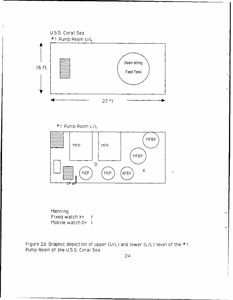
U.S.S. Coral Sea#1 Pump Room U/L
Dealnating
16 ft
16 ftFeed Tank
423 ft
1 Pump Room L/L
L FP MFP
0
Manning:Fixed watch X= 1Mobile watch 0= 1
Figure 2d. Graphic depiction of upper (U/L) and lower (L/L) level of the "'Pump Room of the U.S.S. Coral Sea.
24
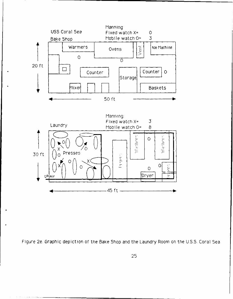
Manning:
USS Coral Sea Fixed watch X= 0
Bake Shop Mobile watch 0= 3
Warmers Ovens Ice Machine
0020 ft
SCounter Storage
ixe Basket
50 ft
Manning:Fixed watch X= 3
Laundry Mobile watch 0= 8
30 ft ( )0 Presses
30 ft () U XA
LP Air Dr y - '
"45 ft
Figure 2e. Graphic depiction of the Bake Shop and the Laundry Room on the U.S.S. Coral Sea
25
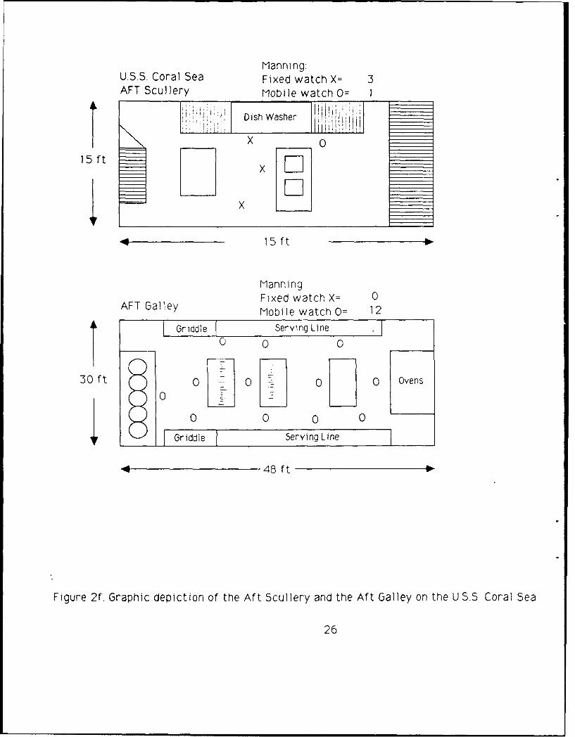
ManningU.S.S. Coral Sea Fixed watch X= 3AFT Scullery Mobile watch 0= I
Dish Washer il H
15 ft x F-]
, 15 ft
ManningFixed watch X= 0
AFT Galley Mobile watch 0= 12
riddle Serving Line
0 0
30 ft 0 0 0 0 Ovens
0
0 0 0 0
Griddle Serving Line
4 48 ft
Figure 2f. Graphic depiction of the Aft Scullery and the Aft Galley on the U 5S. Coral Sea
26
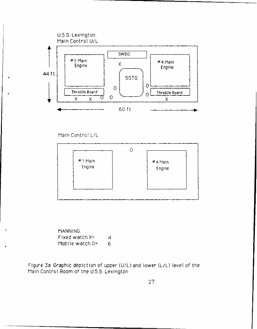
U.S.S. LexingtonMain Control U/L
1 Main 4 Main
Engine XEnin Engine
44 ftSSTG
Tho0 01Throttle Board Throttle Board
60 ft
Main Control L/L
0
# 1 Main #4 MainEngine Engine
MANNING-Fixed watch X= 4Mobile watch 0= 6
Figure 3a. Graphic depiction of upper (U/L) and lower (L/L) level of the
Main Control Room of the U.S.S. Lexington.
27

US.S Lexington
"'1 Fire Room U/L
X0 7xo
28 ft -2 Boiler -111 Boiler XO
4 60Oft
Il Fire Room L/L
0 X X 0
- 2 Boiler ~ I Boiler X
0
Manning;Fixed watch X= 6Mobile watch O=: 6
Figure 3b. Graphic depiction of upper (U/L) and lower (L/L) level of the
Fire Room of the US.S. Lexington.
28
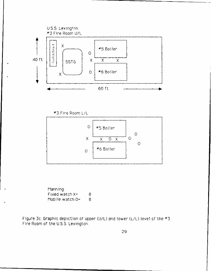
U.S.S. Lexingtona3 Fire Room U/L
K x #5 Boiler
0
40 ft X X X* ~~~SSTG_______
X 0 a6 Boiler
" 60 ft
#3 Fire Room L/L
0 -5 Boiler0
X X 0 X 0
00 #16 Boiler
Manning:Fixed watch X= 8Mobile watch 0= 8
Figure 3c. Graphic depiction of upper (U/L) and lower (L/L) level of the #3Fire Room of the U.S.S. Lexington.
29
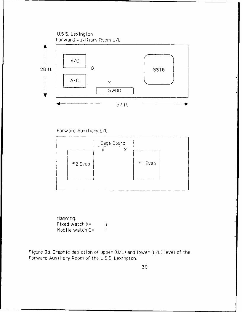
U.S.S. LexingtonForward Auxiliary Room U/L
28 ft / SSTG
SWBD
57 ft
Forward Auxiliary L/L
Gage BoardX X
#2 Evap #1 Evap
Manning:Fixed watch X= 3Mobile watch 0=
Figure 3d Graphic depiction of upper (U/L) and lower (L/L) level of the
Forward Auxiliary Room of the U.S.S. Lexington.
30
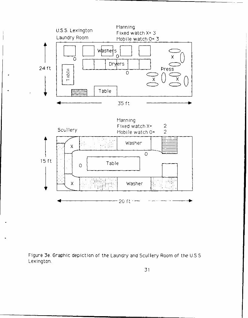
U.S.S. Lexington ManningFixed watch X= 3Laundry Room Mobile watch 0= 3
F- F- W iso l F-124 ft 0 Dr(s Iess
0 _0 0x
X X0 C~Q0Table
S35 ft
ManningFixed watch X= 2Scullery Mobile watch 0= 2
Washer
15 ft Table
X Washer
4
~20 Qt-
Figure 3e. Graphic depiction of the Laundry and Scullery Room of the U.S.SLexington.
31
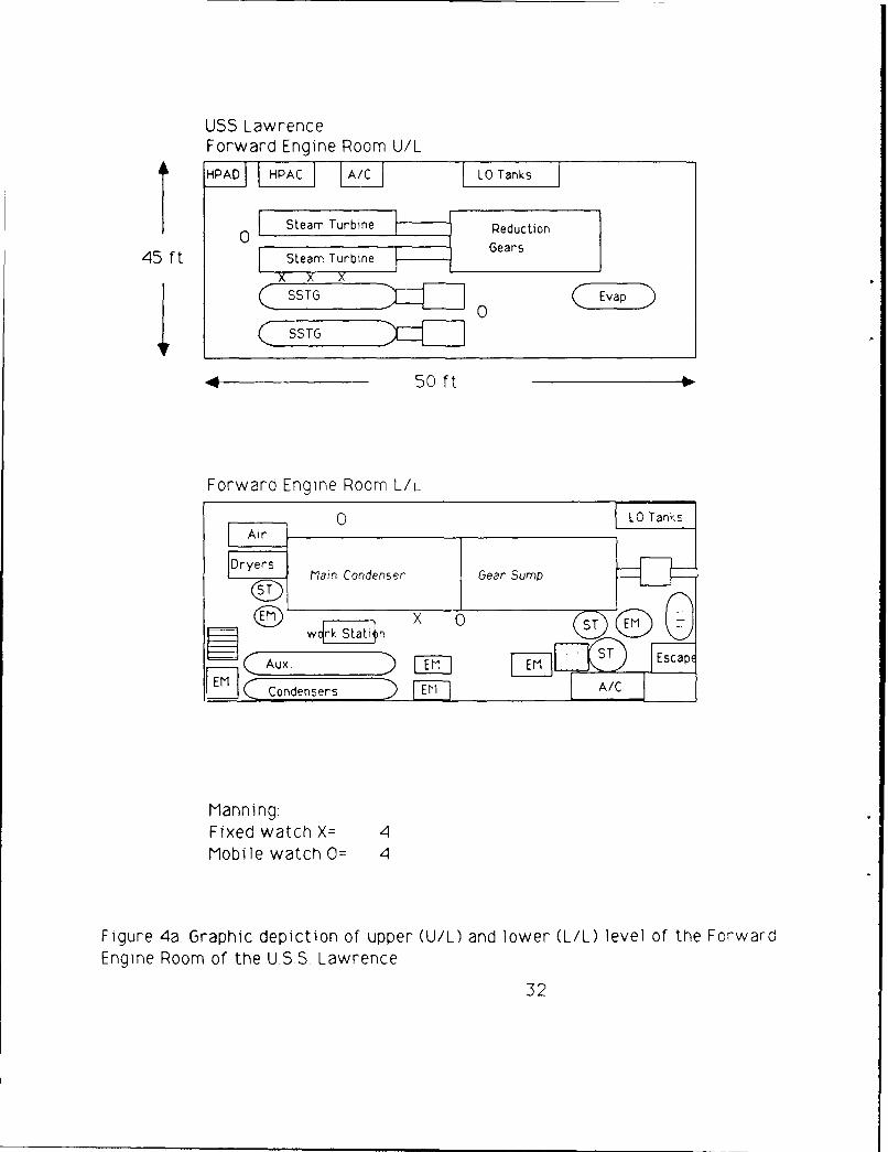
USS LawrenceForward Engine Room U/L
HPAD I PAC A/C LO Tanks
0 Steam Turbn Reduction
45 ft Steam Turbine Gears
X X X(~~~SSTG ]0(Ea
Forward Engine Room L/L
g Main Condeser Gear Sump
w4~atI STST. I EscapE
D Condensers EiA/C
Manning:Fixed watch X= 4Mobile watch 0= 4
Figure 4a Graphic depiction of upper (U/L) and lower (L/L) level of the ForwardEngine Room of the U.S.S Lawrence
32

U.S.S. LawrenceForward Fire Room U/L
dryer Llpazc(ST 0L ST
45 ft Boiler Boiler
(s~L ur ST
" 65 ft
Forward Fire Room L/L
(!"D X U CID (M)
Boiler Boiler
0 0
F 7c) I SFP! pu mp T O
Manning:Fixed watch X= 2Mobile watch 0= 4
Figure 4b. Graphic depiction of upper (U/L) and lower (L/L) level of the
Forward Fire Room of the U.SS. Lawrence,
33
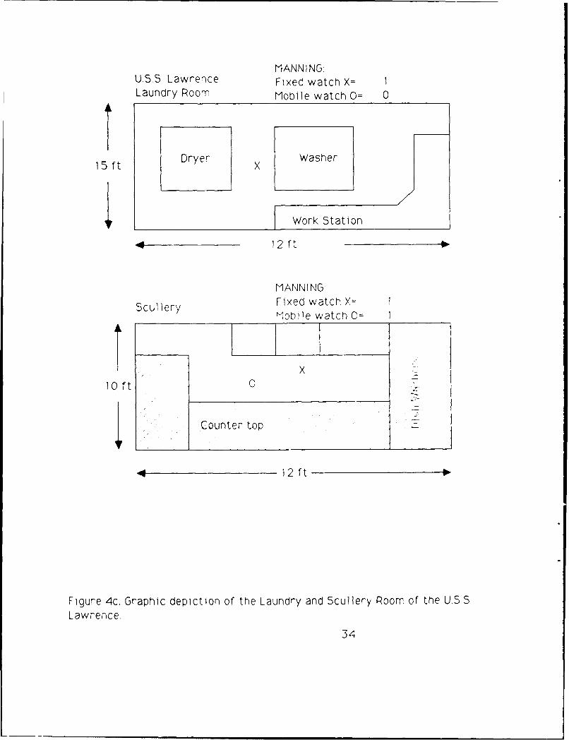
MANNINGU.S.S. Lawrence Fixed watch X= 1Laundry Room Mobile watch 0= 0
15 ft Dryer Washer
Work Station
412ft
MANN I N&
Scullery Fixed watch X= IMobile watchO =
X c
10 ft 0
Counter top
.0 12 ft
Figure 4c. Graphic depiction of the Laundry and Scullery Room of the U.S.S
Lawrence.
34
U.S.S. McCloy
Forward Engine Room U/L
-L ] [LPAC OIL STORAGE
1 -i 115V LPHP ILPAC 1 5
44TURBINE TURBINE h V1115Xi X X
SWITCH BOARDS
39 ft
Forward Engine Room L/L
AUX MtNCNOND _ _ _ _
MAINLO
X CONDENSO LO TRINER
ManningFixed watch X = 4Mobile watch 0 = 2
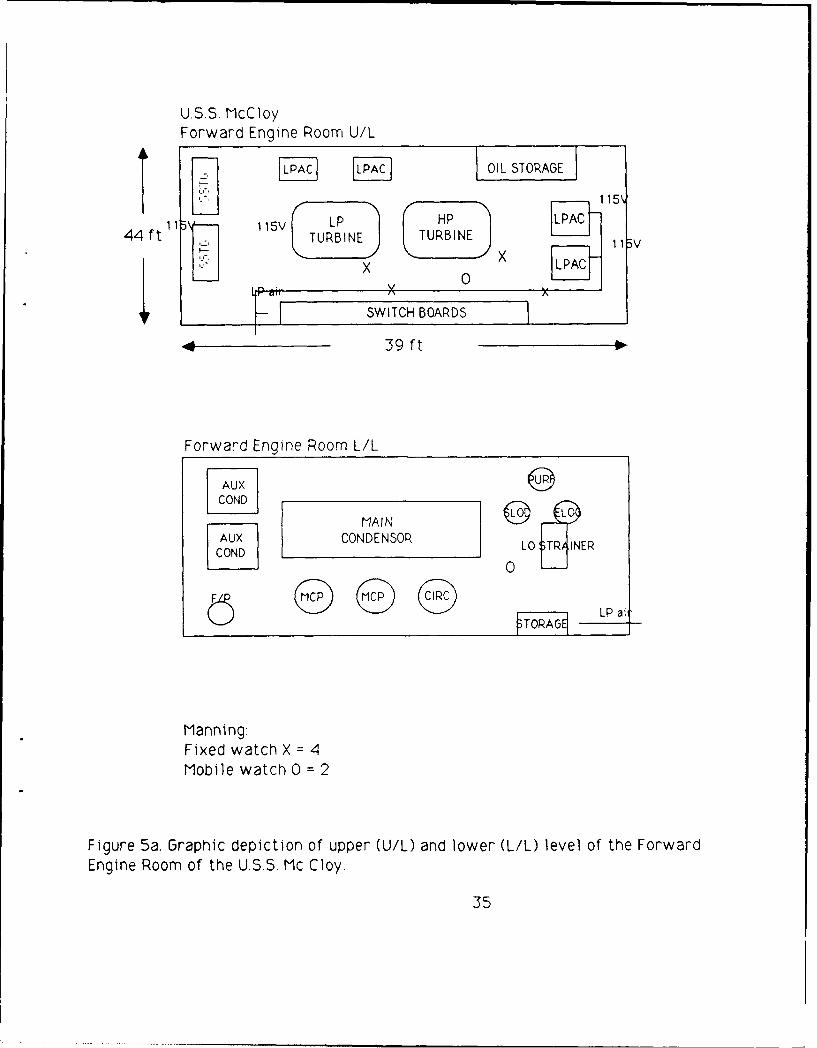
Figure 5a. Graphic depiction of upper (U/L) and lower (L/L) level of the Forward
Engine Room of the U.S.S. Mc Cloy.
35
U.S.S. McCloyForward Fire Room U/L
E 1 BOILER DFT LP air
44 ft 115V 0 X 115V
STO F 2 BOILER
44 39 ft
Forward Fire Room L/L115V
=1 BOILER F
*r2 BOILER
Manning:Fixed watch X = 4Mobile watch 0 = 2
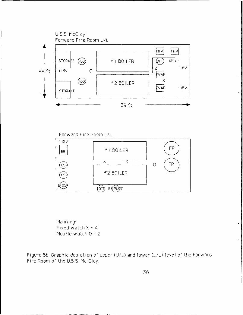
Figure 5b. Graphic depiction of upper (U/L) and lower (L/L) level of the Forward
Fire Room of the U.S.S Mc Cloy.
36
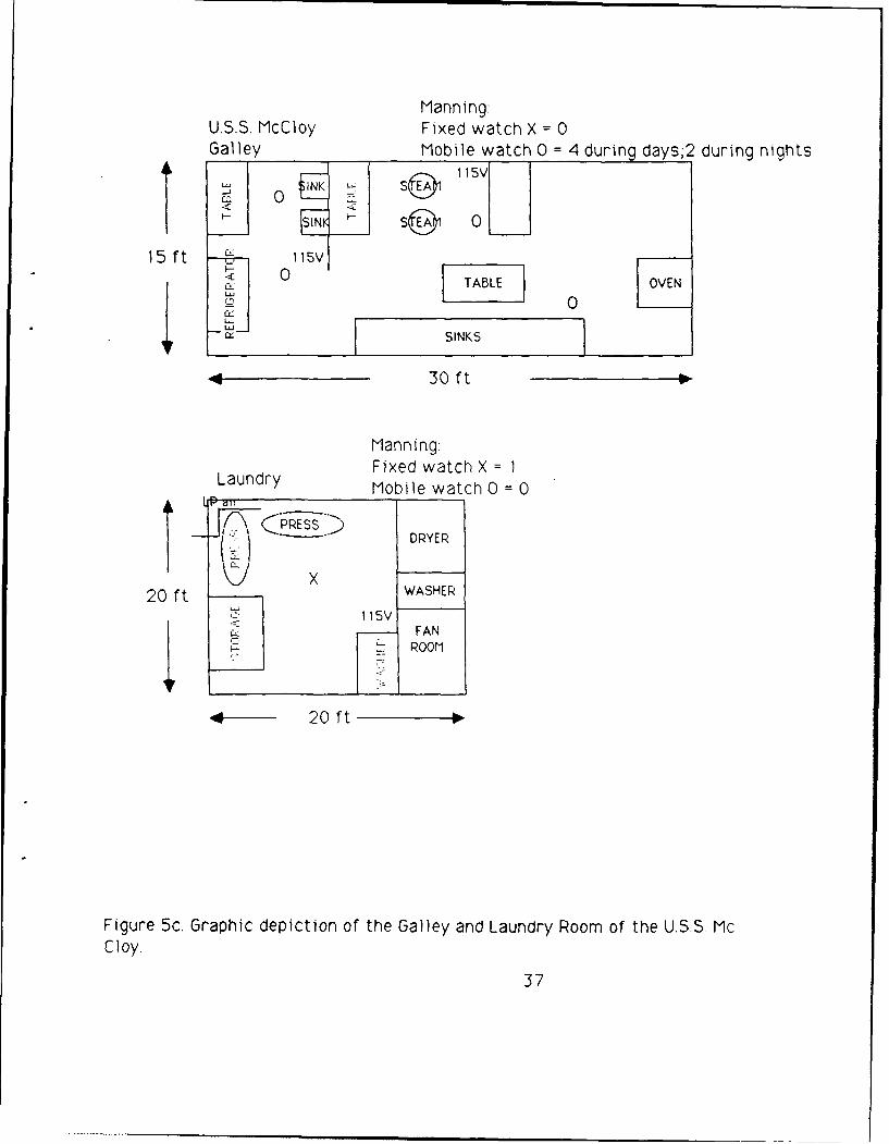
Manning:U.S.S. McCloy Fixed watch X = 0Galley Mobile watch 0 = 4 during days;2 during nights
I-I
< 0
4 F SINKS
4 30Oft
Manning:Fixed watch X = 1
Laundry Mobile watch 0 = 0
20 ft WASHER,: 1 15V
_ FANSROOM
4-"20 ft
Figure 5c. Graphic depiction of the Galley and Laundry Room of the U.S.S. Mc
Cloy.
37
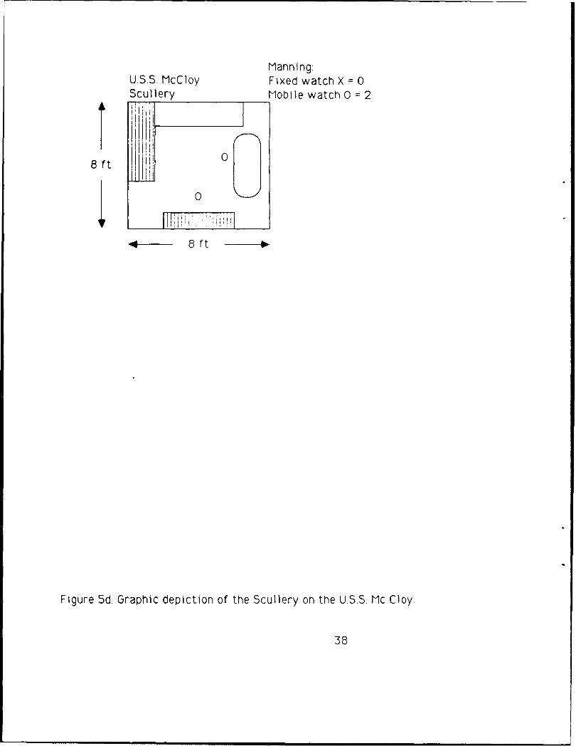
Manning.USS. MCIoy Fixed watch X = 0Scullery Mobile watch 0 =2
8ftIId
8~ ~ ftt
Figure 5d. Graphic depiction of the Scullery on the USS. Mc Cloy.
38
U.S.S. Yarnell
01 Engine Room U/L
0
45 ft 0 a
En app
4 50 ft
MANNIN&Fixed watch X= !Mobile watch 0= 2
Figure 6a. Graphic depiction of upper (U/L) level of the 1 Engine Room of the
U.S.S. Yarnell.
39
U.S.S. YARNELL1 FIRE ROOM U/L
Boller LPA
40 ft FP_ _ __ _ .
Boiler
sca
LP r 50ft
1 Fire Room L/L
LD IBBoiler 0 Str iner
o XL~ X st m
DIrB 0 1A Boiler s cap
Manning-Fixed watch X= 4Mobile watch 0= 3
Figure 6b. Graphic depiction of upper (U/L) and lower (L/L) level of the 1 FireRoom of the U.S.S. Yarnell,
40

Manning.USS. Yarnel IFixed watch X= 0Scullery Mobile watch O= 4
Shelf R~r
0 0
0 f t Washer0 0
.. Washer Washer
10 lft
Manning:Fixed watch X= 0
Laundry Mobile watch0O= 2
Dryer Dryer CWasher
00
Sench Washer
15 ft 0
Figure 6c. Graphic depiction of the Scullery and Laundry Room of the USS.Yarnell.
41
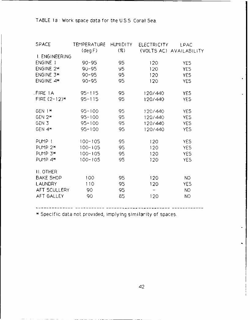
TABLE 1 a : Work space data for the USS. Coral Sea
SPACE TEMPERATURE HUMIDITY ELECTRICITY LPAC(deg.F) (%) (VOLTS AC) AVAILABILITY
I. ENGINEERINGENGINE 1 90-95 95 120 YESENGINE 2* 9U-95 95 120 YESENGINE 3* 90-95 95 120 YESENGINE 4* 90-95 95 120 YES
.FIRE IA 95-115 95 120/440 YESFIRE (2-12)* 95-115 95 120/440 YES
GEN 1* 95-100 95 120/440 YESGEN 2* 95-100 95 120/440 YESGEN 3 95-100 95 120/440 YESGEN 4* 95-100 95 120/440 YES
PUMP 1 100-105 95 120 YESPUMP 2* 100-105 95 120 YESPUMP 3* 100-105 95 120 YESPUMP 4* 100-105 95 120 YES
II. OTHERBAKE SHOP 100 95 120 NOLAUNDRY 110 95 120 YESAFT SCULLERY 90 95 - NOAFT GALLEY 90 85 120 NO
* Specific data not provided, implying similarity of spaces
42

TABLE 1 b : Air vest requirements for the U.S.S. Coral Sea.
SPACE FIXED SHIFTS AIR VESTS REGULATORS TOTALWATCH &HOSES & FILTERS COST
ENGINEERINGENGINE 1 1 3 3 1ENGINE 2* 1 3 3 1ENGINE 3* 1 3 3 1ENGINE 4* 1 3 3 1
FIRE IA 3 3 9 1
FIRE (2- 12)* 33 3 99 11
GEN I* 1 3 3 1GEN 2* 1 3 3 1GEN 3 1 3 3 1GEN 4* 1 3 3 1
PUMP I 1 3 3 1PUMP 2* 1 3 3 IPUMP 3* 1 3 3 1PUMP 4* 1 3 3 1
TOTAL ENGINEERINGNORMAL OPS 48 144 24 $67,968
**[GEN QUARTERS 96 144 36 $69,408)
OTHERBAKE SHOP 0 1 0 0LAUNDRY 3 1 3 1AFT SCULLERY 3 3 9 1AFT GALLEY 0 3 0 0
TOTAL OTHERNORMAL OPS 6 12 2 $5,664
COMPLETE OUTFITNORMAL OPS 54 156 26 $73,632
**[GEN QUARTERS 102 156 38 $75,072)
• Specific data not provided, implying similarity of spaces.** Because manning during GQ can double, manning for fixed watch was calculated as Fixed WatchX 2. Regulators and Filters were adjusted to meet this increased demand. A Regulator & Filter assembly wasprovided as support for every 3 air vests in a work space.Note: Additional LPAC requirements are listed in Table 9.
43
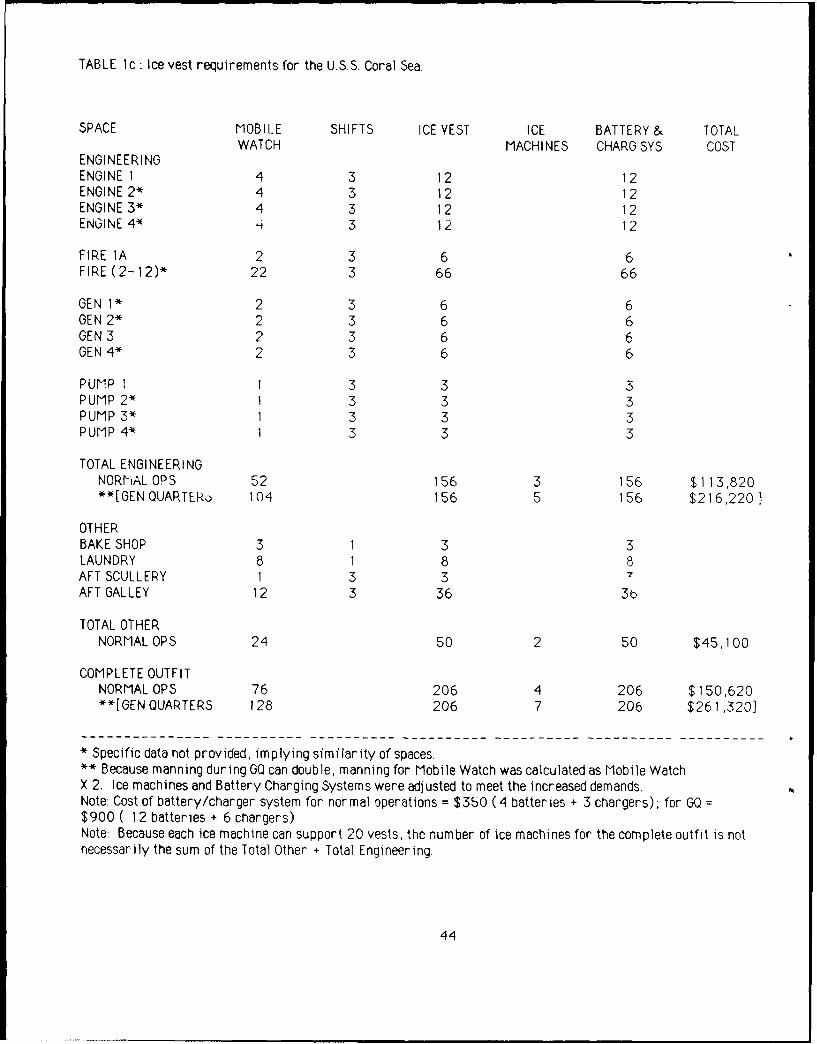
TABLE c: Ice vest requirements for the U.S.S. Coral Sea.
SPACE MOBILE SHIFTS ICE VEST ICE BATTERY & TOTALWATCH MACHINES CHARO SYS COST
ENGINEERINGENGINE 1 4 3 12 12ENGINE 2* 4 3 12 12ENGINE 3* 4 3 12 12ENGINE 4* '4 3 1 2 1 2
FIRE 1A 2 3 6 6FIRE (2-12)* 22 3 66 66
GEN 1* 2 3 6 6GEN 2* 2 3 6 6GEN 3 2 3 6 6GEN 4* 2 3 6 6
PUMP I 1 3 3 3PUMP 2* 1 3 3 3PUMP 3* 1 3 3 3PUMP 4* 1 3 3 3
TOTAL ENGINEERINGNORhiAL OPS 52 156 3 156 $113,820**[GEN QUARTER3 104 156 5 156 $216,220]
OTHERBAKE SHOP 3 1 3 3LAUNDRY 8 1 8 8AFT SCULLERY 1 3 3 7AFT GALLEY 12 3 36 3b
TOTAL OTHERNORMALOPS 24 50 2 50 $45,100
COMPLETE OUTFITNORMAL OPS 76 206 4 206 $150,620**[GEN QUARTERS 128 206 7 206 $261,320]
* Specific data not provided, implying similarity of spaces.** Because manning during GO can double, manning for Mobile Watch was calculated as Mobile WatchX 2. Ice machines and Battery Charging Systems were adjusted to meet the increased demands.Note: Cost of battery/charger system for normal operations = $350 (4 batteries + 3 chargers); for GQ =$900 ( 12 batteries + 6 chargers)Note: Because each ice machine can support 20 vests, the number of ice machines for the complete outfit is notnecessarily the sum of the Total Other + Total Engineering.
44

TABLE 2a Work space data for the U.S.S. Lexington.
SPACE TEMPERATURE HUMIDITY ELECTRICITY LPAC
(deg.F) (%) (VOLTS AC) AVAILABILITY
I. ENGINEERINGMAIN CONTROL 120 95 120/440 YES
AFT ENGINE* 110 95 120/440 YES
FIRE 1 120 95 120/440 YES
FIRE 2* 120 95 120/440 YES
FIRE 3 120 95 120/440 YES
FIRE 4* 120 95 120/440 YES
FWD AUX 95 85 120/440 YES
AFT AUX* 95 90 120/440 YES
II. OTHERLAUNDRY 110 90 120 YES
SCULLERY 95 90 120 NO
--------------------------------------------- ------------ ------------
* Specific data not provided, implying similarity of spaces.
45
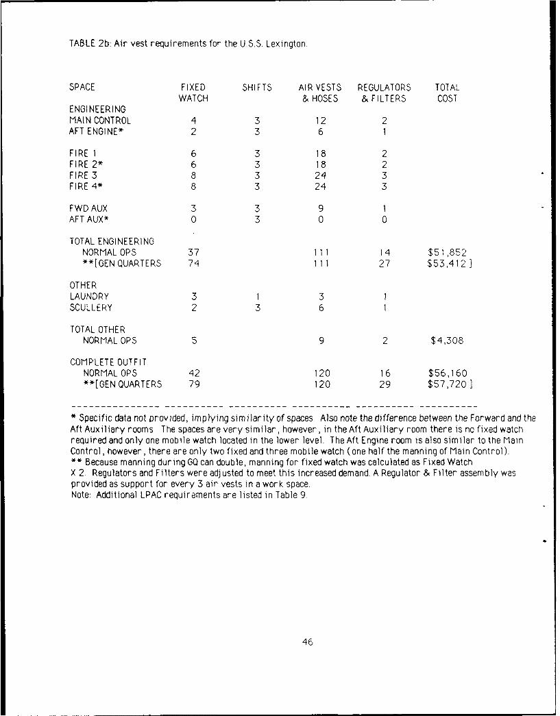
TABLE 2b: Air vest requirements for the U.S.S. Lexington.
SPACE FIXED SHIFTS AIR VESTS REGULATORS TOTALWATCH & HOSES & FILTERS COST
ENGINEERINGMAIN CONTROL 4 3 12 2AFT ENGINE* 2 3 6 1
FIRE 1 6 3 18 2FIRE 2* 6 3 18 2FIRE 3 8 3 24 3FIRE 4* 8 3 24 3
FWD AUX 3 3 9 1AFT AUX* 0 3 0 0
TOTAL ENGINEERINGNORMALOPS 37 111 14 $51,852**[GEN QUARTERS 74 111 27 $53,412]
OTHERLAUNDRY 3 1 3 1SCULLERY 2 3 6 1
TOTAL OTHERNORMAL OPS 5 9 2 $4,308
COMPLETE OUTFITNORMAL OPS 42 120 16 $56,160**[GEN QUARTERS 79 120 29 $57,720]
* Specific data not provided, implying similarity of spaces. Also note the difference between the Forward and theAft Auxiliary rooms The spaces are very similar, however, in the Aft Auxiliary room there is no fixed watchrequired and only one mobile watch located in the lower level. The Aft Engine room is also similar to the MainControl, however, there are only two fixed and three mobile watch (one half the manning of Main Control).** Because manning during GQ can double, manning for fixed watch was calculated as Fixed WatchX 2. Regulators and Filters were adjusted to meet this increased demand. A Regulator & Filter assembly wasprovided as support for every 3 air vests in a work space.Note: Additional LPAC requirements are listed in Table 9.
46

TABLE 2c : Ice vest requirements for the U.S.S. Lexington.
SPACE MOBILE SHIFTS ICE VEST ICE BATTERY& TOTALWATCH MACHINES CHARG SYS COST
ENGINEERINGMAIN CONTROL 6 3 18 18
AFT ENGINE* 3 3 9 9
FIRE 1 6 3 18 18
FIRE 2* 6 3 18 18FIRE 3 8 3 24 24FIRE 4* 8 3 24 24
FWD AUX 1 3 3 3AFT AUX* 1 3 3 3
TOTAL ENGINEERINGNORMAL OPS 39 1 17 2 117 $83,290**[GEN QUARTERS 78 117 4 117 $164,240)
OTHERLAUNDRY 3 1 3 3
SCULLERY 2 3 6 6
TOTAL OTHERNORMAL OPS 5 9 1 9 $13,430
COMPLETE OUTFITNORMALOPS 44 126 3 126 $96,720**[GEN QUARTERS 83 126 4 126 $169,370]
* Specific data not provided, implying similarity of spaces.
** Because manning during GO can double, manning for Mobile Watch 'Vas calculated as Mobile WatchX 2. Ice machines and Battery Charging Systems were adjusted to meet the increased demands.Note: Cost of battery/charger system for normal operations = $350 (4 batteries + 3 chargers); for GO =
$900 ( 12 batteries + 6 chargers)Note: Because each ice machine can support 20 vests, the number of ice machines for the complete outfit is notnecessarily the sum of the Total Other + Total Engineering.
47
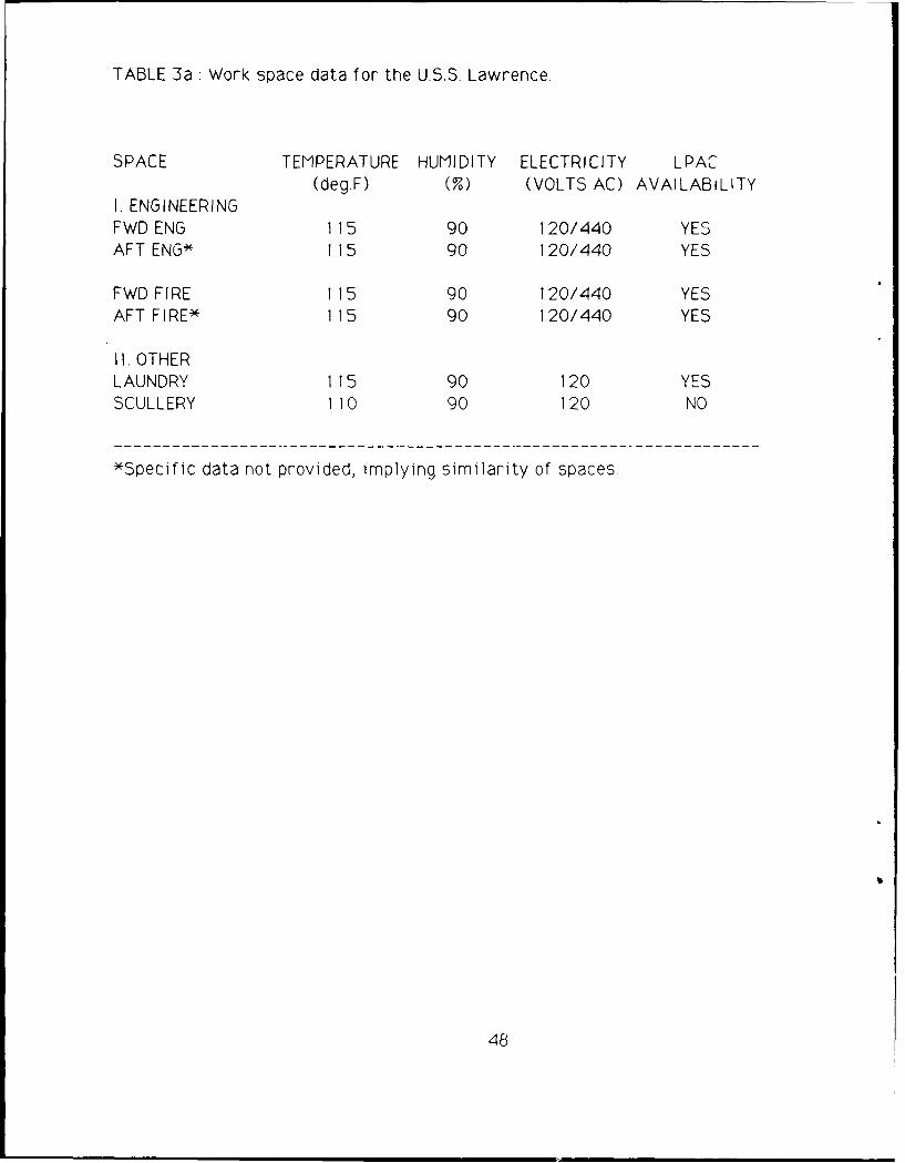
TABLE 3a: Work space data for the U.S.S. Lawrence.
SPACE TEMPERATURE HUMIDITY ELECTRICITY LPAC(degF) (%) (VOLTSAC) AVAILABILITY
1. ENGINEERINGFWD ENG 115 90 120/440 YESAFT ENG* 115 90 120/440 YES
FWD FIRE 115 90 120/440 YESAFT FIRE* 115 90 120/440 YES
II. OTHERLAUNDRY 115 90 120 YESSCULLERY 110 90 120 NO
*Specific data not provided, implying similarity of spaces.
48
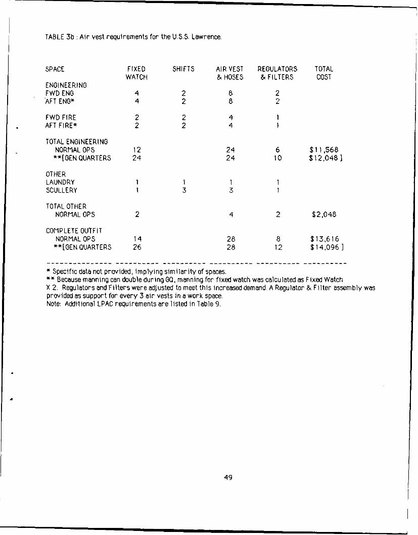
TABLE 3b Air vest requirements for the U.S.S. Lawrence.
SPACE FIXED SHIFTS AIR VEST REGULATORS TOTALWATCH & HOSES & FILTERS COST
ENGINEERINGFWD ENG 4 2 8 2AFT ENG* 4 2 8 2
FWD FIRE 2 2 4 1AFT FIRE* 2 2 4 1
TOTAL ENGINEERINGNORMAL OPS 12 24 6 $11,568**[GEN QUARTERS 24 24 10 $12,048)
OTHERLAUNDRY 1 1 1 1SCULLERY 1 3 3 1
TOTAL OTHERNORMAL OPS 2 4 2 $2,048
COMPLETE OUTFITNORMAL OPS 14 28 8 $13,616**[GEN QUARTERS 26 28 12 $14,096 3
* Specific data not provided, implying similarity of spaces.
** Because manning can double during GQ, manning for fixed watch was calculated as Fixed WatchX 2. Regulators and Filters were adjusted to meet this increased demand. A Regulator & Filter assembly wasprovided as support for every 3 air vests in a work space.Note: Additional LPAC requirements are listed in Table 9.
4
49
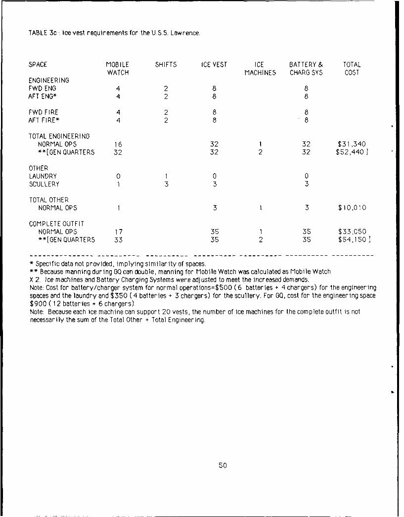
TABLE 3c : Ice vest requirements for the U.S.S. Lawrence.
SPACE MOBILE SHIFTS ICE VEST ICE BATTERY& TOTALWATCH MACHINES CHARG SYS COST
ENGINEERINGFWD ENG 4 2 8 8AFT ENG* 4 2 8 8
FWD FIRE 4 2 8 8AFT FIRE* 4 2 8 8
TOTAL ENGINEERINGNORMAL OPS 16 32 1 32 $31,340**[GEN QUARTERS 32 32 2 32 $52,4401
OTHERLAUNDRY 0 1 0 0SCULLERY 1 3 3 3
TOTAL OTHERNORMAL OPS 1 3 1 3 $10,010
COMPLETE OUTFITNORMAL OPS 17 35 1 35 $33,050**[GEN QUARTERS 33 35 2 35 $54,1501
* Specific data not provided, implying similarity of spaces.** Because manning during GQ can double, manning for Mobile Watch was calculated as Mobile WatchX 2. Ice machines and Battery Charging Systems were adjusted to meet the increased demands.Note: Cost for battery/charger system for normal operations=$500 (6 batteries + 4 chargers) for the engineeringspaces and the laundry and $350 ( 4 batteries + 3 chargers) for the scullery. For G0, cost for the engineering space$900 ( 12 batteries + 6 chargers).Note: Because each ice machine can support 20 vests, the number of ice machines for the complete outfit is notnecessarily the sum of the Total Other + Total Engineering.
50

TABLE 4a: Work space data for the U.S.S. Nashville.
SPACE TEMPERATURE HUMIDITY ELECTRICITY LPAC(deg.F) (%) (VOLTS AC) AVAILABILITY
I. ENGINEERINGENGINE 1 * * 120/440 YESENGINE 2 * 120/440 YES
II. OTHERLAUNDRY * * 120 YESSCULLERY * * 120 NO
• Data were not reported in reference (4)
51
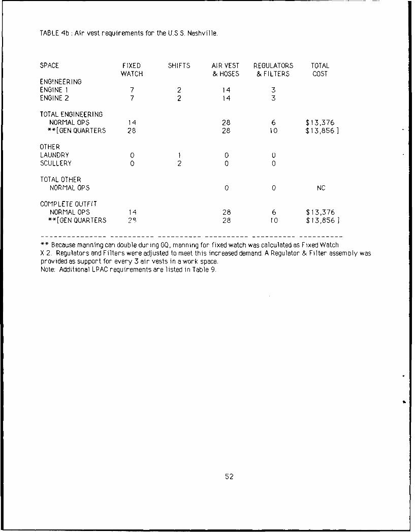
TABLE 4b :Air vest requirements for the U.S.S. Nashville.
SPACE FIXED SHIFTS AIR VEST REGULATORS TOTALWATCH & HOSES & FILTERS COST
ENGINEERINGENGINE 1 7 2 14 3ENGINE 2 7 2 14 3
TOTAL ENGINEERINGNORMAL OPS 14 28 6 $13,376**[GEN QUARTERS 28 28 10 $13,8561
OTHERLAUNDRY 0 1 0 0SCULLERY 0 2 0 0
TOTAL OTHERNORMAL OPS 0 0 NC
COMPLETE OUTFITNORMALOPS 14 28 6 $13,376
**[GEN QUARTERS 23 28 10 $13,856]
** Because manning can double during GQ, manning for fixed watch was calculated as Fixed WatchX 2. Regulators and Filters were adjusted to meet this increased demand. A Regulator & Filter assembly wasprovided as support for every 3 air vests in a work space.Note: Additional LPAC requirements are listed in Table 9.
52
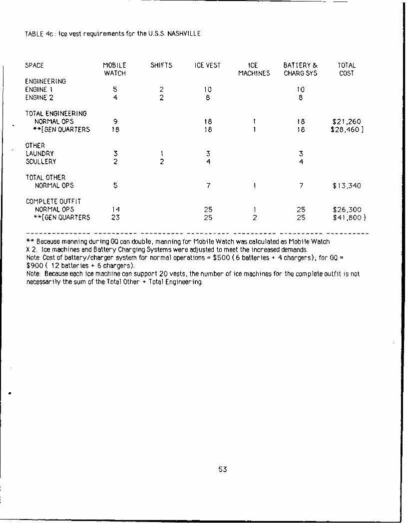
TABLE 4c : Ice vest requirements for the U.S.S. NASHVILLE
SPACE MOBILE SHIFTS ICE VEST ICE BATTERY & TOTALWATCH MACHINES CHARGSYS COST
ENGINEERING
ENGINE 1 5 2 10 10ENGINE 2 4 2 8 8
TOTAL ENGINEERINGNORMAL OPS 9 18 1 18 $21,260
**[GEN QUARTERS 18 18 1 18 $28,460]
OTHERLAUNDRY 3 1 3 3SCULLERY 2 2 4 4
TOTAL OTHERNORMALOPS 5 7 1 7 $13,340
COMPLETE OUTFITNORMAL OPS 14 25 1 25 $26,300
**[GEN QUARTERS 23 25 2 25 $41,800]
** Because manning during GQ can double, manning for Mobile Watch was calculated as Mobile WatchX 2. Ice machines and Battery Charging Systems were adjusted to meet the increased demands.Note: Cost of battery/charger system for normal operations = $500 (6 batteries + 4 chargers); for GQ =
$900 ( 12 batteries + 6 chargers).Note: Because each ice machine can support 20 vests, the number of ice machines for the complete outfit is notnecessarily the sum of the Total Other + Total Engineering.
53
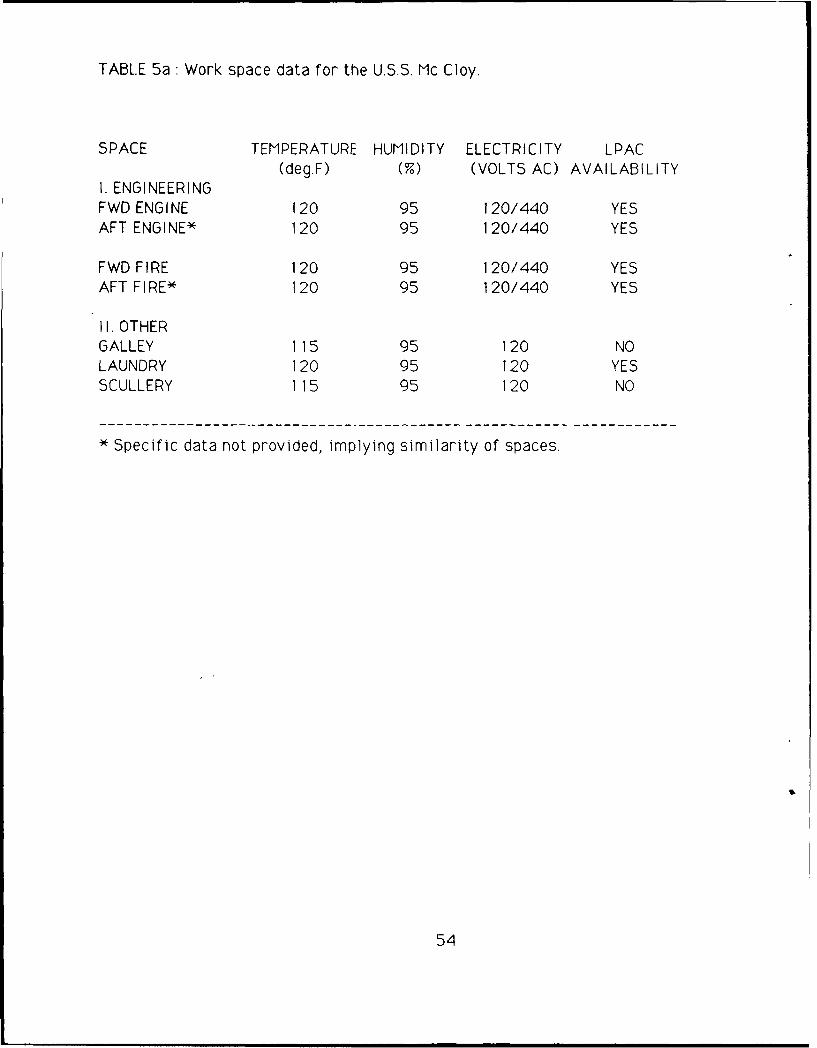
TABLE 5a: Work space data for the U.S.S. Mc Cloy.
SPACE TEMPERATURE HUMIDITY ELECTRICITY LPAC(deg.F) (%) (VOLTS AC) AVAILABILITY
I. ENGINEERINGFWD ENGINE 120 95 120/440 YESAFT ENGINE* 120 95 120/440 YES
FWD FIRE 120 95 120/440 YESAFT FIRE* 120 95 120/440 YES
II. OTHERGALLEY 115 95 120 NOLAUNDRY 120 95 120 YESSCULLERY 115 95 120 NO
* Specific data not provided, implying similarity of spaces.
54
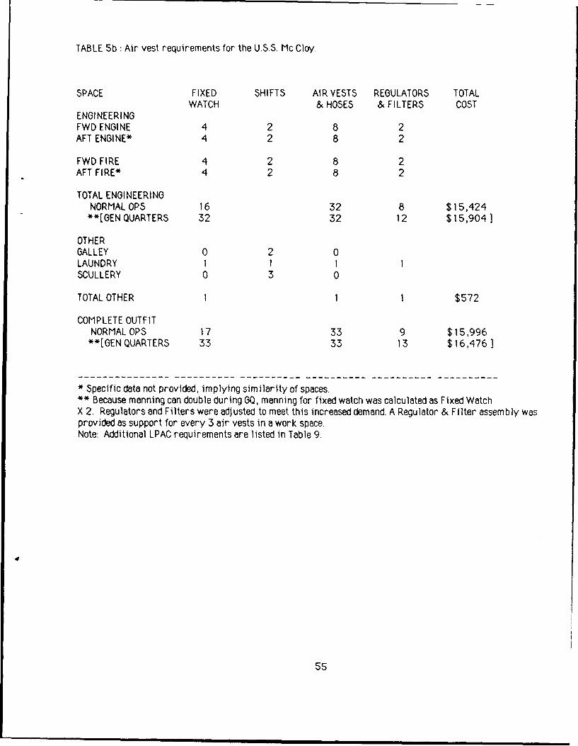
TABLE 5b : Air vest requirements for the U.S.S. Mc Cloy.
SPACE FIXED SHIFTS AIR VESTS REGULATORS TOTALWATCH & HOSES & FILTERS COST
ENGINEERINGFWD ENGINE 4 2 8 2AFT ENGINE* 4 2 8 2
FWD FIRE 4 2 8 2AFT FIRE* 4 2 8 2
TOTAL ENGINEERINGNORMAL OPS 16 32 8 $15,424
**[GEN QUARTERS 32 32 12 $15,904]
OTHERGALLEY 0 2 0LAUNDRY 1 I I 1SCULLERY 0 3 0
TOTAL OTHER 1 1 1 $572
COMPLETE OUTFITNORMAL OPS 17 33 9 $15,996**[GEN QUARTERS 33 33 13 $16,476]
* Specific data not provided, implying similarity of spaces.** Because manning can double during GO, manning for fixed watch was calculated as Fixed WatchX 2. Regulators and Filters were adjusted to meet this increased demand. A Regulator & Filter assembly wasprovided as support for every 3 air vests in a work space.Note: Additional LPAC requirements are listed in Table 9.
55

TABLE 5c : Ice vest requirements for the U.5. Mc Cloy
SPACE MOBILE SHIFTS ICE VEST ICE BATTERY & TOTALWATCH MACHINE CHAROSYS COST
ENGINEERINGFWD ENGINE 2 2 4 4AFT ENGINE* 2 2 4 4
FWD FIRE 2 2 4 4AFT FIRE* 2 2 4 4
TOTAL ENGINEERINGNORMALOPS 8 16 1 16 $19,820**[GEN QUARTERS 16 16 1 16 $26,220]
OTHERGALLEY*** 3 2 6 6LAUNDRY 0 1 0 0SCULLERY 2 3 6 6
TOTAL OTHERNORMALOPS 5 12 1 12 $16,040
COMPLETE OUTFITNORMALOPS 13 28 1 28 $27,560**[GEN QUARTERS 21 28 1 28 $33,960]
* Specific data not provided, implying similarity of spaces.
** Because manning curing C-0 can double, mnning for Mobile Watch was calculated as Mobile WatchX 2. Ice machines and Battery Charging Systems are adjusted to meet the increased demands.*** According to Figure 5c, there are 4 mobile watches during the day and 2 at night in the galley.For simplicity, we used an average figure of three mobile watches for the calculation.Note: Cost for battery/charger system for normal operations=$500 (6 batteries + 4 chargers) for the engineer-ing spaces, galley, and laundry and $350 ( 4 batteries + 3 chargers) for scullery. For GQ, cost for engineeringspace = $900 ( 12 batteries + 6 chargers).Note: Because each ice machine can support 20 vests, the number of ice machines for the complete outfit is notnecessarily the sum of the Total Other + Total Engineering.
56
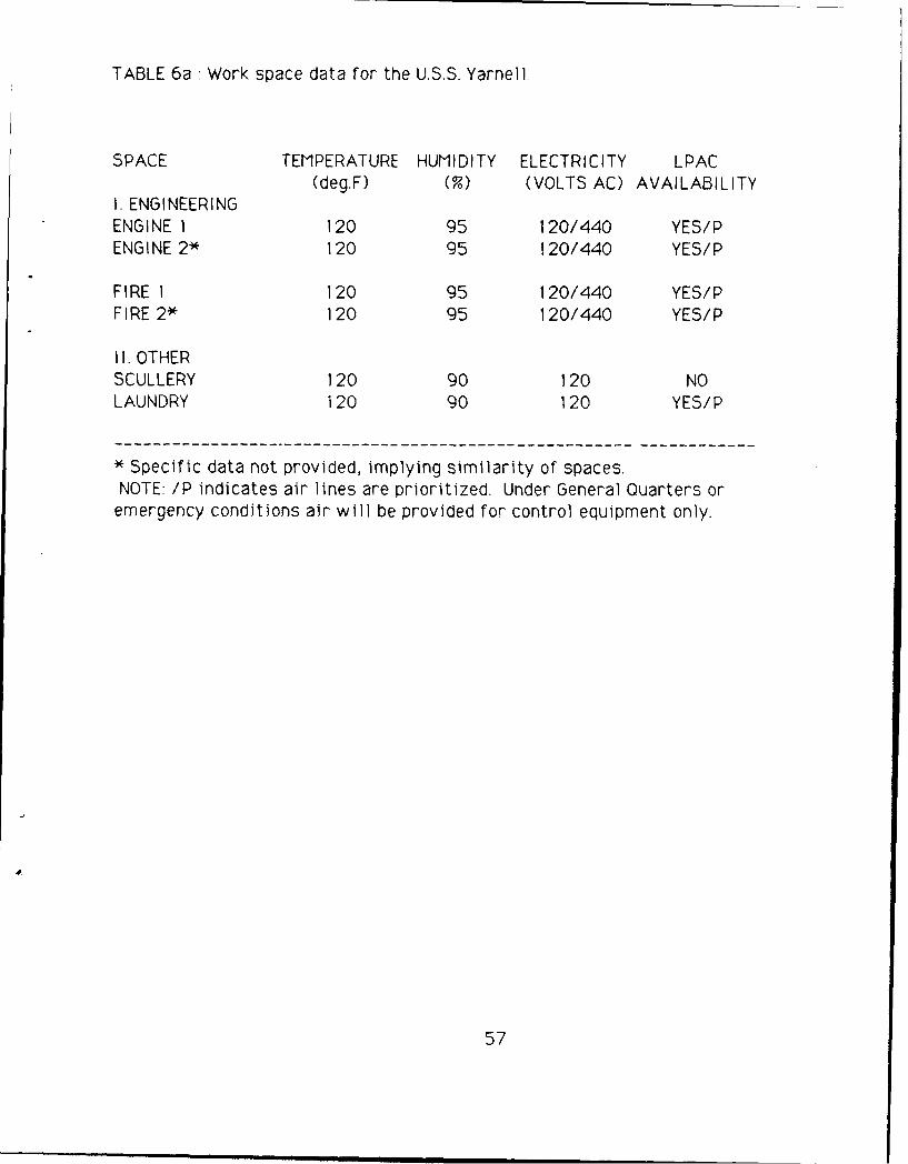
TABLE 6a: Work space data for the U.S.S. Yarnell,
SPACE TEMPERATURE HUMIDITY ELECTRICITY LPAC(deg.F) (%) (VOLTS AC) AVAILABILITY
I. ENGINEERINGENGINE 1 120 95 120/440 YES/PENGINE 2* 120 95 120/440 YES/P
FIRE 1 120 95 120/440 YES/PFIRE 2* 120 95 120/440 YES/P
II. OTHERSCULLERY 120 90 120 NOLAUNDRY 120 90 120 YES/P
* Specific data not provided, implying similarity of spaces.NOTE: /P indicates air lines are prioritized. Under General Quarters oremergency conditions air will be provided for control equipment only.
57
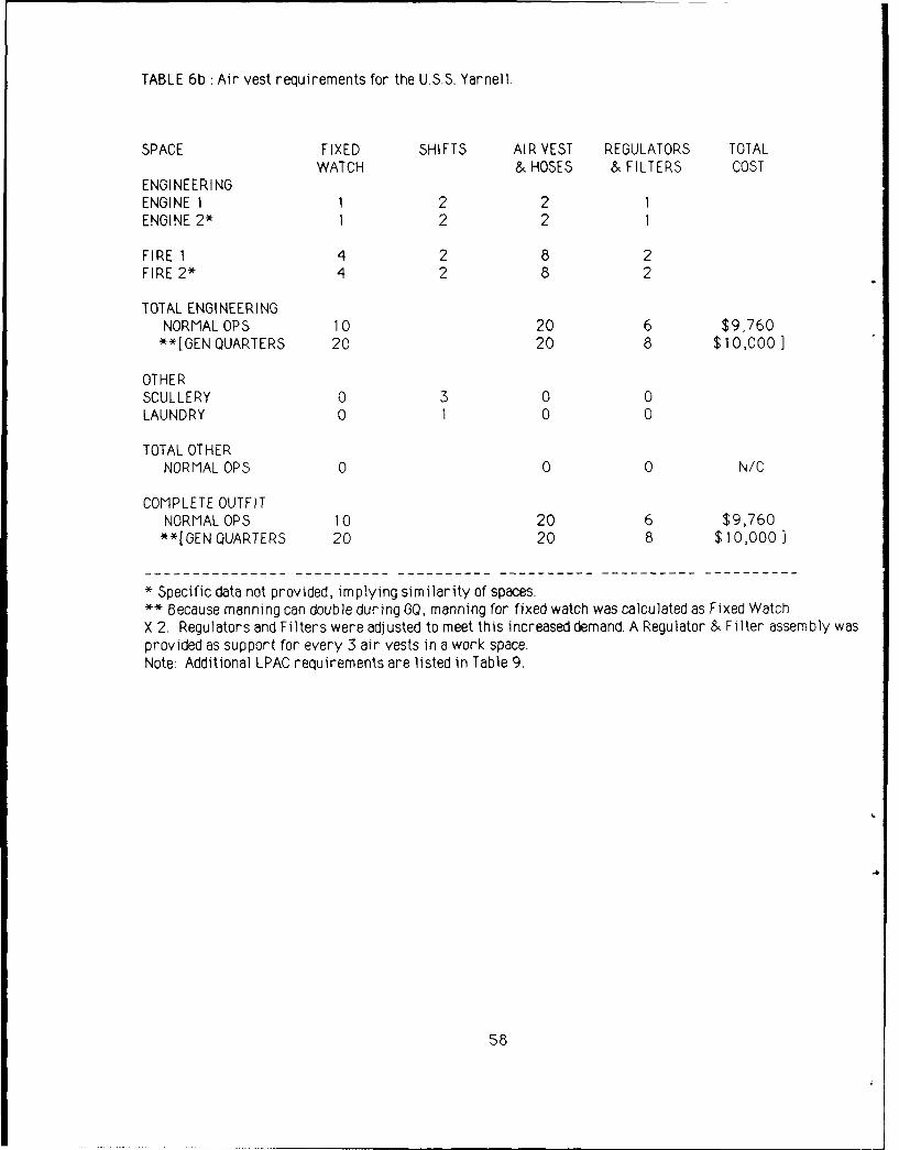
TABLE 6b : Air vest requirements for the U.SS. Yarnell.
SPACE FIXED SHIFTS AIR VEST REGULATORS TOTALWATCH & HOSES & FILTERS COST
ENGINEERINGENGINE 1 1 2 2 1ENGINE 2* 1 2 2 1
FIRE 1 4 2 8 2FIRE 2* 4 2 8 2
TOTAL ENGINEERINGNORMALOPS 10 20 6 $9,760**[GEN QUARTERS 20 20 8 $10,000]
OTHERSCULLERY 0 3 0 0LAUNDRY 0 1 0 0
TOTAL OTHERNORMAL OPS 0 0 0 N/C
COMPLETE OUTFITNORMAL OPS 10 20 6 $9,760
**[GEN QUARTERS 20 20 8 $10,000]
* Specific data not provided, implying similarity of spaces.** Because manning can double during GQ, manning for fixed watch was calculated as Fixed WatchX 2. Regulators and Filters were adjusted to meet this increased demand. A Regulator & Filter assembly wasprovided as support for every 3 air vests in a work space.Note: Additional LPAC requirements are listed in Table 9.
58
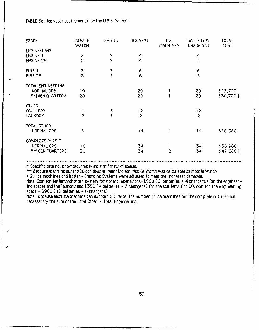
TABLE 6c: Ice vest requirements for the U.S.S. Yarnell.
SPACE MOBILE SHIFTS ICE VEST ICE BATTERY & TOTALWATCH MACHINES CHARG SYS COST
ENGINEEP!NGENGINE 1 2 2 4 4ENGINE 2* 2 2 4 4
FIRE 1 3 2 6 6FIRE 2* 3 2 6 6
TOTAL ENGINEERINGNORMAL OPS 10 20 1 20 $22,700
**[GEN QUARTERS 20 20 1 20 $30,700)
OTHERSCULLERY 4 3 12 12LAUNDRY 2 1 2 2
TOTAL OTHERNORMAL OPS 6 14 1 14 $16,580
COMPLETE OUTFITNORMAL OPS 16 34 1 34 $30,980**[GEN QUARTERS 26 34 2 34 $47,280 ]
* Specific data not provided, implying similarity of spaces.** Because manning during GO can double, manning for Mobile Watch was calculated as Mobile WatchX 2. Ice machines and Battery Charging Systems were adjusted to meet the increased demands.Note: Cost for battery/charger system for normal operations=$500 (6 batteries + 4 chargers) for the engineer-ing spaces and the laundry and $350 ( 4 batteries + 3 chargers) for the scullery. For GQ, cost for the engineeringspace = $900 ( 12 batteries + 6 chargers).Note: Bxause each ice machine can support 20 vests, the number of ice machines for the complete outfit is notnecessarily the sum of the Total Other + Total Engineering.
59
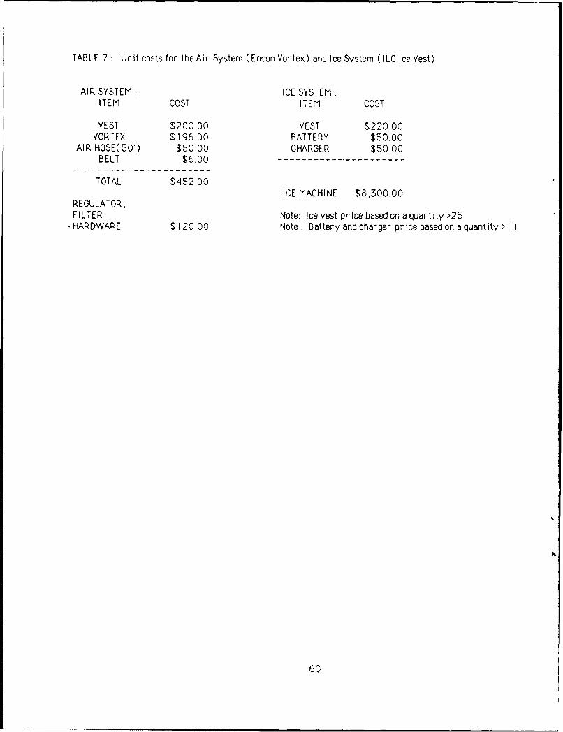
TABLE 7 : Unit costs for the Air System (Encon Vortex) and Ice System (ILC Ice Vest).
AIR SYSTEM ICE SYSTEMITEM COST ITEM COST
VEST $200 00 VEST $220.00VORTEX $19600 BATTERY $50.00
AIR HOSE(50') $50,00 CHARGER $50.00BELT $6.00
TOTAL $452 00'E MACHINE $8,300.00
REGULATOR,FILTER; Note. Ice vest price based on a quantity >25
* HARDWARE $120.00 Note : Battery and charger price based on a quantity >1 1
60
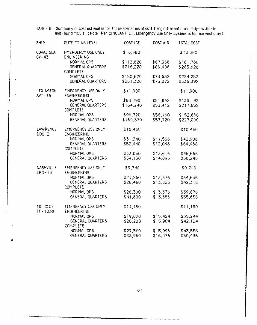
TABLE 8 : Summary of cost estimates for three scenarios of outfitting different class ships with air
and liquid MCS's (Note: Per CINCLANTFLT, Emergency Use Only System is for ice vest only).
SHIP OUTFITTING LEVEL COST ICE COST AIR TOTAL COST
CORAL SEA EMERGENCY USE ONLY $18,380 $18,380CV-43 ENGINEERING
NORMALO05 $113,820 $67,968 $181,788GENERAL QUARTERS $216,220 $69,408 $285,628
COMPLETENORMALOPS $150,620 $73,632 $224,252GENERAL QUARTERS $261,320 $75,072 $336,392
LEXINGTON EMERGENCY USE ONLY $1 1 ,900 $1 1,900AVT-16 ENGINEERING
NORMAL OPS $83,290 $51,852 $135,142GENERAL QUARTERS $164,240 $53,412 $217,652
COMPLETENORMAL OPS $96,720 $56,160 $152,880GENERAL QUARTERS $169,370 $57,720 $227,090
LAWRENCE EMERGENCY USE ONLY $10,460 $10,460DDG-2 ENGINEERING
NORMAL OPS $31,340 $11,568 $42,908GENERAL QUARTERS $52,440 $12,048 $64,488
COMPLETENORMAL OPS $33,050 $ 13,6 16 $46,666GENERAL QUARTERS $54,150 $14,096 $68,246
NASHVILLE EMERGENCY USE ONLY $9,740 $9,740LPD- 13 ENGINEERING
NORMAL OPS $21,260 $13,376 $34,636GENERAL QUARTERS $28,460 $13,856 $42,316
COMPLETENORMALOPS $26,300 $13,376 $39,676GENERAL QUARTERS $41,800 $13,856 $55,656
MC CLOY EMERGENCY USE ONLY $1 1,180 $11,180FF- 1038 ENGINEERING
NORMAL OPS $19,820 $15,424 $35,244GENERAL QUARTERS $26,220 $15,904 $42,124
COMPLETENORMAL OPS $27,560 $15,996 $43,556GENERAL QUARTERS $33,960 $16,476 $50,436
61
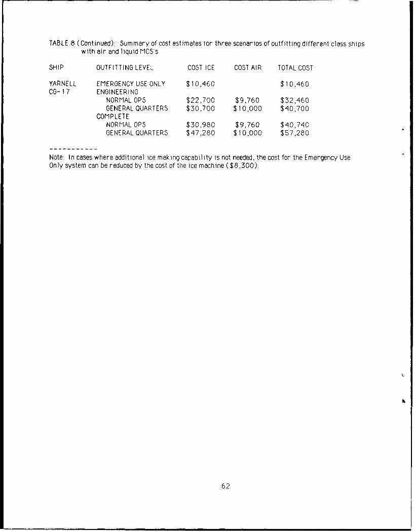
TABLE 8 (Continued): Summary of cost estimates Ior three scenarios of outfitting different class ships
with air and liquid MCS's.
SHIP OUTFITTING LEVEL COST ICE COST AIR TOTAL COST
YARNELL EMERGENCY USE ONLY $10,460 $10,460CG-17 ENGINEERING
NORMAL OPS $22,700 $9,760 $32,460GENERAL QUARTERS $30,700 $10,000 $40,700
COMPLETENORMAL OPS $30,980 $9,760 $40,740GENERAL QUARTERS $47,280 $10,000 $57,280
Note: In cases where additional ice making capability is not needed, the cost for the Emergency UseOnly system can be reduced by the cost of the ice machine ($8,300).
62
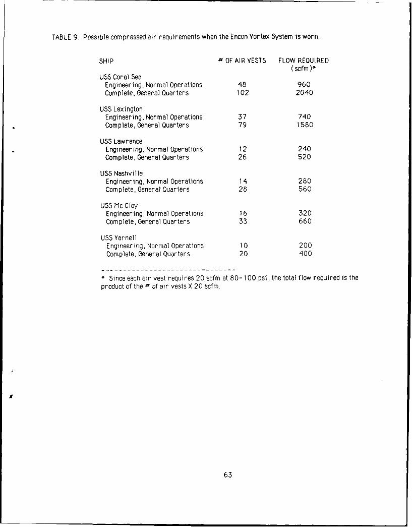
TABLE 9. Possible compressed air requirements when the Encon Vortex System is worn.
SHIP = OF AIR VESTS FLOW REQUIRED(scfm)*
USS Coral SeaEngineering, Normal Operations 48 960Complete, General Quarters 102 2040
USS LexingtonEngineering, Normal Operations 37 740Complete, General Quarters 79 1580
USS LawrenceEngineering, Normal Operations 12 240Complete, General Quarters 26 520
USS NashvilleEngineering, Normal Operations 14 280Complete, General Quarters 28 560
USS Mc CloyEngineering, Normal Operations 16 320Complete, General Quarters 33 660
USS YarnellEngineering, Normal Operations 10 200Complete, General Quarters 20 400
* Since each air vest requires 20 scfm at 80- 1 00 psi, the total flow required is theproduct of the = of air vests X 20 scfm
63