Embed Size (px)
Citation preview

REPORT DOCUMENTATION PAGE Form Approved OMB No. 0704-0188
The public reportmg burden for th1s collection of mformation is estimated to average 1 hour per response. includmg the time for rev>ewing instruct>ons. searclhing existing data sources. gathering and mmnta1mng the data needed. and completing and rev1ew1ng the collection of 1nforma t1 on. Send comments regarding th1s burden est1mate or any other aspect o fth1s collection of mformat1on . 1nclud1ng suggestions for reduc1ng the burden. to the Department of Defense. ExecutiVe Serv1ce D>rectorate (0704-0188) Respondents should be aware that notwithstanding any other prov1s1on of law. no person shall be sub;ect to any penalty for fall ing to comply w1th a collect>on of 1nformat1on if 1t does not display a currently valid OMB control number
PLEASE DO NOT RETURN YOUR FORM TO THE ABOVE ORGANIZATION.
1. REPORT DATE (DD-MM-YYYY) 12. REPORT TYPE 3. DATES COVERED (From- To)
31-08-2010 Final Report June 2006-11ay 2010 4. TITLE AND SUBTITLE Sa. CONTRACT NUMBER
(DEPSCOR 06) -A DISPERSED MONOPROPELLANT MICROSLUG APPROACH
FOR DISCRETE SATELLITE MICROPROPULSION Sb. GRANT NUMBER
F A9550-06-l-0364
Sc. PROGRAM ELEMENT NUMBER
6. AUTHOR(S) Sd. PROJECT NUMBER
Darren L. Hitt
Se. TASK NUMBER
Sf. WORK UNIT NUMBER
7. PERFORMING ORGANIZATION NAME(S) AND ADDRESS(ES) 8. PERFORMING ORGANIZATION
Mechanical Engineering Program REPORT NUMBER
School of Engineering University of Vermont
Burlington, Vermont 05405
9. SPONSORING/MONITORING AGENCY NAME(S) AND ADDRESS(ES) 10. SPONSOR/MONITOR'S ACRONYM(S)
Dr. Mitat Birkan Space Propulsion and Power
Air Force Office of Scientific Research 11. SPONSOR/MONITOR'S REPORT
4015 Wilson Blvd. NUMBER(S)
Arlington, VA 22203-1954 AFRL-OSR-VA-TR-2012-0447
12. DISTRIBUTION/AVAILABILITY STATEMENT
A
13. SUPPLEMENTARY NOTES
14. ABSTRACT Miniaturized spacecraft (nanosats) require propulsion systems capable of providing extremely low levels of thrust (1-1 00 uN) and impulse (1 uN ·
sec). We have demonstrated the feasibility of a 'digital' monopropellant propulsion system in which the delivery of the monopropellant is in the
form of discrete and dispersed microscopic slugs. By utilizing recent developments in experimental microfluidics, a controlled slug formation
process represents a virtual 'self-valving' mechanism which affords finer resolution than a micro-valve for a continuous stream. Through a
combination of experiment and computation, we have demonstrated the ability to controllably deliver monopropellant fuel as dispersed droplets
leading to a throttling of the flow rate by as much as 50% over a continuous flow. This throttling capability allows impulse bits to be
correspondingly reduced. In parallel, microfabrication efforts have produced a novel catalytic micro-reactor prototype for the monopropellant decomposition using ruthernium-oxide nanorods. Finally, extensive computational studies have yielded comprehensive performance information
critical to the micro-scale design of efficient supersonic nozzles for incorporation in the propulsion system.
1S. SUBJECT TERMS
micropropulsion, hydrogen-peroxide, micro-nozzle, chemical decomposition, nanosats
16. SECURITY CLASSIFICATION OF: 17. LIMITATION OF 18. NUMBER
a. REPORT b. ABSTRACT c. THIS PAGE ABSTRACT OF PAGES
19a. NAME OF RESPONSIBLE PERSON
Darren L. Hitt 19b. TELEPHONE NUMBER (Include area code)
Reset
802-656-1940 Standard Form 298 (Rev. 8/98)
Prescribed by ANSI Std Z39 18 Adobe Professional 7.0
AFOSR 2009-10 Progress Report:
“DEPSCOR06: A Dispersed Monopropellant Microslug Approach for discrete Satellite Micropropulsion”
Darren L. Hitt (PI)Mechanical Engineering Program
Walter J. Varhue (Co-I)Electrical & Computer Engineering Program
School of EngineeringUniversity of Vermont
Burlington, Vermont 05405
Grant #: FA9550-06-1-0364Program Officer: Mitat Birkan, AFOSR
(August, 2010)
D.L. Hitt - 2010 Progress Report
Overview
This report summarizes the progress made during the final year of the grant entitled “DEPSCOR06: A Dispersed Monopropellant Microslug Approach for Discrete Satellite Micropropulsion.” The final year of the project has met with substantial success in achieving a key goal in the project: the demonstration of the ability to deliver liquid monopropellant in the form of well-controlled, dispersed liquid slugs. Experiments have characterized the slug formation process and demonstrated that an effective throttling of the monopropellant flow rate of nearly 50%. This is a significant achievement in the ability to reduce minimum impulse bits for nanosat micropropulsion. Success was also achieved in developing time-dependent computational models of the high-speed droplet formation process which will allow further design optimization of the system and explore still smaller length scales flow regimes not yet experimentally accessible to our instrumentation. Experimental delays associated with the microfabrication of the micro-catalyst chamber have been overcome and prototype chambers are now being completed and should be ready for testing in the very near future. Lastly, our ongoing computational efforts at characterizing supersonic micronozzle flows have been extended to more complex flow scenarios including: 3-D transient micronozzle operation, condensation onset in the expander, and multiphase-flow effects on thrust production. A patent application for a micro-scale plug nozzle has been filed jointly with Purdue University.
The detailed progress information, delineated in the pages to follow, is grouped according to three primary research tasks:
Task #1 - Experimental and computational studies of the controlled formation of dispersed monopropellant micro-slugs as a fuel delivery scheme.
Task #2 - Computational studies of the performance characteristics of supersonic micro-nozzles
Task #3 - Experimental design and fabrication of a catalytic micro-reactor using ruthenium-oxide nanostructures
D.L. Hitt - 2010 Progress Report
Research Objectives & Progress for 2009-10
TASK #1 - “Monopropellant Micro-Slug Delivery and Optimization”
Overview. The primary objective of this investigation is to create a discrete, monopropellant delivery system for use in the nanosat attitude control thruster. This system will make use of the steady, periodic formation of microslugs at a microchannel junction to allow finer resolution of impulse-bits than current microvalve technology allows. Efforts involve a combination of experimental and computational approaches as described below.
A. Experimental Study of Microslug Formation
Scope of the Project. This sub-project is focused on the creation and testing of a pressure-driven microfluidic flow system to study the effects of geometry and material properties on the microslug formation phenomena. The inspiration for this work is derived largely by a series of articles authored by Cubaud and collaborators involving complex flow structures formed by immiscible fluids in microchannels. [1-6] These experiments include flow visualizations using high speed video and flow characterization using two-phase pressure drop across the microchannel. Using these techniques a clearly defined relationship between the primary inlet parameter, pressure ratio of the monopropellant and an inert gas, and the microslug characteristics will be defined for various microchannel sizes and geometries.
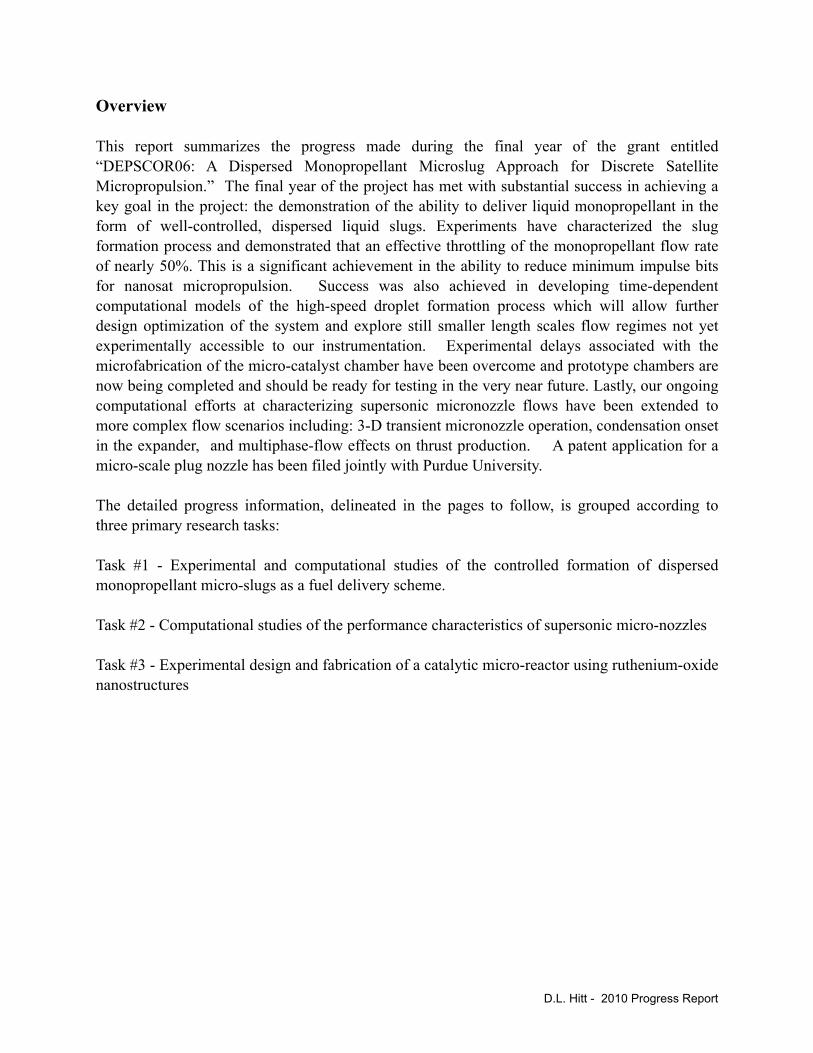
Experimental Design & Testing. To characterize the microslug formation by the inlet parameters, a pressure-driven flow system was developed. As a starting point for evaluation, an off-the-shelf microfluidic chip, manufactured by Micralyne, Inc. was used as shown in Figure A-1.1.
Figure 1.A.1: Geometry of the Micralyne 50 µm x 20 µm Microfluidic Chip
D.L. Hitt - 2010 Progress Report

A schematic of the experimental setup is shown in Figure 1.A.2. By controlling the pressure ratio of the air and water lines, a range of microslugs can be generated. Using flow visualization and image reconstruction software, the size and frequency of the microslugs can be calculated, which can be used to calculate a propellant flow rate which can lead to calculations of a range of thruster performance calculations.
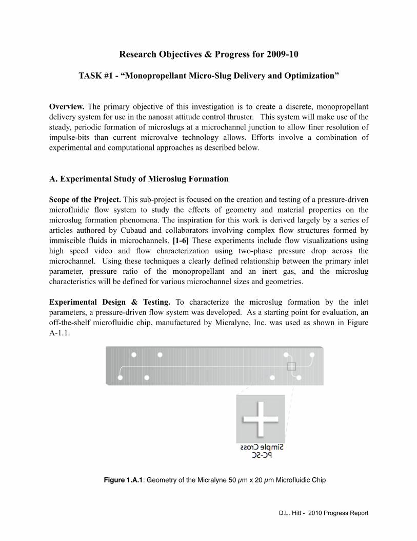
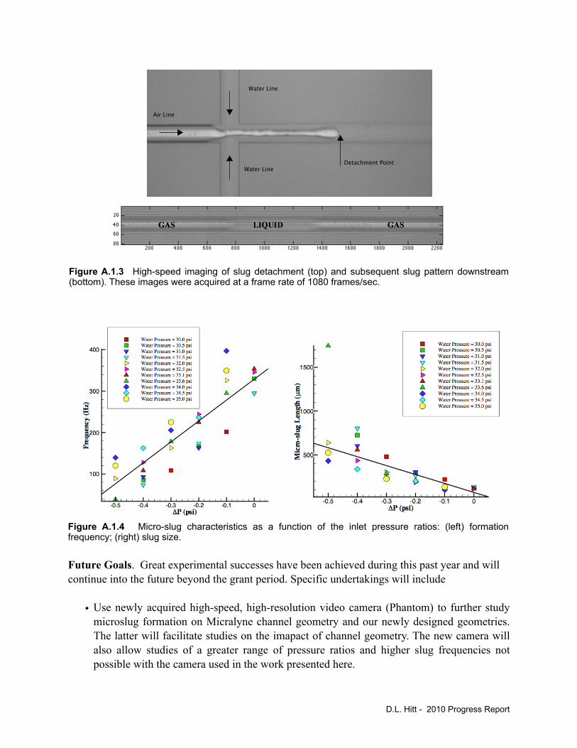
Summary of Findings. A pressure-driven flow apparatus for studying microslug formation was designed and tested using high speed video imaging and digital image analysis. Using this apparatus and methodology developed, the Micralyne-based microfluidic chip design was studied and microslug formation was characterized for a range of inlet pressure ratios. The results of this study has been submitted to the AIAA Journal of Propulsion and Power. [7] An illustrative case of the high-speed imaging of the slug formation is shown in Figure 1.A.3. From such data, the slug characteristics (size, frequency) can be correlated with inlet pressure conditions (Figure 1.A.4). In terms of propulsion consequences, one may estimate the time-averaged thrust level associated with different slug size/frequency combinations by modeling the slugs as a hydrogen-peroxide monopropellant. The result is shown in Figure 1.A.5. Here is it seen that an effective throttling of the baseline time-averaged thrust is possible with a magnitude of nearly 50% by the alteration of the slug characteristics.
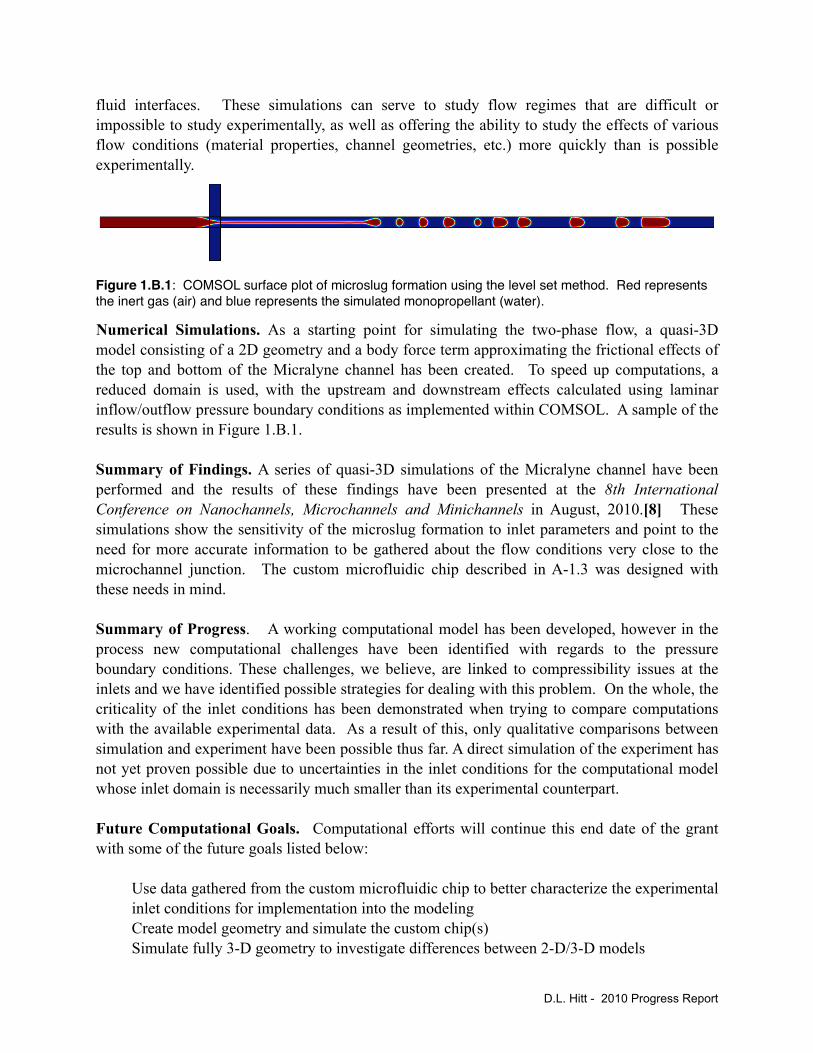
Current efforts are focused on the study the effects of channel size on microslug formation. To this end two custom microfluidic chips were designed as shown in Figure A-1.6. In addition to having a cross-sectional area an order of magnitude smaller than the Micralyne chip (O[100 µm]) these chips will allow access to pressure-drop data via ports within the microchannel. These channels will be built by Dr. Varhue’s group in collaboration with the University of Maryland Nanotechnology Center and/or the microfabrication facilities at NASA GSFC.
D.L. Hitt - 2010 Progress Report
Pressurized Air Lines
Digital!
Manometers
Outlet
MicrochannelPressurized Water Line
Water!Reservoir
Figure 1.A.2: Schematic of Microfluidic Flow Apparatus
Future Goals. Great experimental successes have been achieved during this past year and will continue into the future beyond the grant period. Specific undertakings will include
• Use newly acquired high-speed, high-resolution video camera (Phantom) to further study microslug formation on Micralyne channel geometry and our newly designed geometries. The latter will facilitate studies on the imapact of channel geometry. The new camera will also allow studies of a greater range of pressure ratios and higher slug frequencies not possible with the camera used in the work presented here.
D.L. Hitt - 2010 Progress Report
Figure A.1.3 High-speed imaging of slug detachment (top) and subsequent slug pattern downstream (bottom). These images were acquired at a frame rate of 1080 frames/sec.
Water Line
Air Line
Water Line
Detachment Point
Figure A.1.4 Micro-slug characteristics as a function of the inlet pressure ratios: (left) formation frequency; (right) slug size.
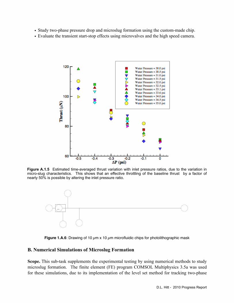
• Study two-phase pressure drop and microslug formation using the custom-made chip.• Evaluate the transient start-stop effects using microvalves and the high speed camera.
B. Numerical Simulations of Microslug Formation
Scope. This sub-task supplements the experimental testing by using numerical methods to study microslug formation. The finite element (FE) program COMSOL Multiphysics 3.5a was used for these simulations, due to its implementation of the level set method for tracking two-phase
D.L. Hitt - 2010 Progress Report
Figure A.1.5 Estimated time-averaged thrust variation with inlet pressure ratios, due to the variation in micro-slug characteristics. This shows that an effective throttling of the baseline thrust by a factor of nearly 50% is possible by altering the inlet pressure ratio.
Figure 1.A.6: Drawing of 10 µm x 10 µm microfluidic chips for photolithographic mask
fluid interfaces. These simulations can serve to study flow regimes that are difficult or impossible to study experimentally, as well as offering the ability to study the effects of various flow conditions (material properties, channel geometries, etc.) more quickly than is possible experimentally.
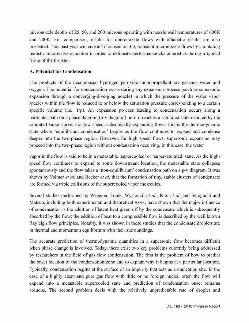
Numerical Simulations. As a starting point for simulating the two-phase flow, a quasi-3D model consisting of a 2D geometry and a body force term approximating the frictional effects of the top and bottom of the Micralyne channel has been created. To speed up computations, a reduced domain is used, with the upstream and downstream effects calculated using laminar inflow/outflow pressure boundary conditions as implemented within COMSOL. A sample of the results is shown in Figure 1.B.1.
Summary of Findings. A series of quasi-3D simulations of the Micralyne channel have been performed and the results of these findings have been presented at the 8th International Conference on Nanochannels, Microchannels and Minichannels in August, 2010.[8] These simulations show the sensitivity of the microslug formation to inlet parameters and point to the need for more accurate information to be gathered about the flow conditions very close to the microchannel junction. The custom microfluidic chip described in A-1.3 was designed with these needs in mind.
Summary of Progress. A working computational model has been developed, however in the process new computational challenges have been identified with regards to the pressure boundary conditions. These challenges, we believe, are linked to compressibility issues at the inlets and we have identified possible strategies for dealing with this problem. On the whole, the criticality of the inlet conditions has been demonstrated when trying to compare computations with the available experimental data. As a result of this, only qualitative comparisons between simulation and experiment have been possible thus far. A direct simulation of the experiment has not yet proven possible due to uncertainties in the inlet conditions for the computational model whose inlet domain is necessarily much smaller than its experimental counterpart.
Future Computational Goals. Computational efforts will continue this end date of the grant with some of the future goals listed below:
Use data gathered from the custom microfluidic chip to better characterize the experimental inlet conditions for implementation into the modelingCreate model geometry and simulate the custom chip(s)Simulate fully 3-D geometry to investigate differences between 2-D/3-D models
Figure 1.B.1: COMSOL surface plot of microslug formation using the level set method. Red represents the inert gas (air) and blue represents the simulated monopropellant (water).
D.L. Hitt - 2010 Progress Report

Evaluate the importance of compressible effects using COMSOL 4.0 capabilitiesPerform comprehensive parametric study of material properties (surface tension, viscosity, contact angle) on microslug formation.This sub-task supplements the experimental testing by using numerical methods to study microslug formation. The finite element (FE) program COMSOL Multiphysics 3.5a was used for these simulations, due to its implementation of the level set method for tracking two-phase fluid interfaces. These simulations can serve to study flow regimes that are difficult or impossible to study experimentally, as well as offering the ability to study the effects of various flow conditions (material properties, channel geometries, etc.) more quickly than is possible experimentally.
D.L. Hitt - 2010 Progress Report
Research Objectives & Progress for 2009-10 (Hitt)
TASK #3 - “Numerical Simulations of Supersonic Flows in Micronozzles”
Overview. This work is part of an ongoing numerical investigation of supersonic, viscous flow in a MEMS-based micronozzle. The model for this study is derived from the original NASA/Goddard Space Flight Center hydrogen peroxide monopropellant prototype thruster by Hitt et al. 2001. Here we extend the previous 3D numerical models in order to investigate the potential for condensation of the gaseous flow-field as well as delineate performance characteristics of transient operation. Owing to the large surface area to volume ratio of a 3D MEMS device, heat transfer from the flow field and viscous forces have been shown to significantly alter micronozzle flow field characteristics. The potential exists for large viscous, subsonic layers to grow with downstream distance in the expander. For appropriate flow parameters, these subsonic layers from adjacent expander walls have been shown to merge and thus render the entire cross section of the flow field subsonic. This scenario greatly reduces nozzle performance characteristics.
One method employed to compensate for these subsonic layers is to increase the micronozzle expansion angle. However, doing so generates transverse velocity components and results in geometric losses. It has been shown that a 30° expander half-angle balances this trade-off between losses associated with the viscous, subsonic layer and geometric losses. Moreover, it was also found that heat transfer from the flow-field acts to reduces viscous forces (viscosity decreases with decreasing temperature), reduce subsonic layer growth (via a reduction in the local speed of sound), further increases flow velocity (via Rayleigh flow principles), and as such, increase micronozzle performance.
As a result of the cold space environment combined with the high thermal conductivity of the silicon substrate in which the micronozzle geometry is etched (k = 150 W/m·K at 300K), it is expected that the substrate will provide negligible insulation, result in reduced nozzle wall temperatures, and allow for significant heat loss from the nozzle flow-field. This notion of heat loss from the flow is further supported by the inherently transient usage of a station keeping thruster. Although monopropellant decomposition is highly exothermic, the amount of heat produced during a single duty cycle is not sufficient to appreciably raise the substrate temperature and thus the micronozzle walls are well approximated as being isothermal.
This past year’s efforts have been targeted at delineating the range of micronozzle flow parameters that will lead to condensation within the flow-field and to determine the impact on nozzle performance. Specifically, we examined throat Reynolds numbers of 800 and 160 for
D.L. Hitt - 2010 Progress Report
micronozzle depths of 25, 50, and 200 microns operating with nozzle wall temperatures of 600K and 200K. For comparison, results for micronozzle flows with adiabatic results are also presented. This past year we have also focused on 3D, transient micronozzle flows by simulating realistic microvalve actuation in order to delineate performance characteristics during a typical firing of the thruster.
A. Potential for Condensation
The products of the decomposed hydrogen peroxide monopropellant are gaseous water and oxygen. The potential for condensation exists during any expansion process (such as supersonic expansion through a converging-diverging nozzle) in which the pressure of the water vapor species within the flow is reduced to or below the saturation pressure corresponding to a certain specific volume (i.e., 1/ρ). An expansion process leading to condensation occurs along a particular path on a phase diagram (p-v diagram) until it reaches a saturated state denoted by the saturated vapor curve. For low speed, subsonically expanding flows, this is the thermodynamic state where ‘equilibrium condensation’ begins as the flow continues to expand and condense deeper into the two-phase region. However, for high speed flows, supersonic expansion may proceed into the two-phase region without condensation occurring. In this case, the water
vapor in the flow is said to be in a metastable ‘supercooled’ or ‘supersaturated’ state. As the high-speed flow continues to expand to some downstream location, the metastable state collapses spontaneously and the flow takes a ‘non-equilibrium’ condensation path on a p-v diagram. It was shown by Volmer et al. and Becker et al. that the formation of tiny, stable clusters of condensate are formed via triple collisions of the supercooled vapor molecules.
Several studies performed by Wegener, Frank, Wyslouzil et al., Kim et al. and Setoguchi and Matsuo, including both experimental and theoretical work, have shown that the major influence of condensation is the addition of latent heat given off by the condensate which is subsequently absorbed by the flow; the addition of heat to a compressible flow is described by the well known Rayleigh flow principles. Notably, it was shown in these studies that the condensate droplets are in thermal and momentum equilibrium with their surroundings.
The accurate prediction of thermodynamic quantities in a supersonic flow becomes difficult when phase change is involved. Today, there exist two key problems currently being addressed by researchers in the field of gas flow condensation. The first is the problem of how to predict the onset location of the condensation zone and to explain why it begins at a particular location. Typically, condensation begins at the surface of an impurity that acts as a nucleation site. In the case of a highly clean and pure gas flow with little or no foreign nuclei, often the flow will expand into a metastable supercooled state and prediction of condensation onset remains arduous. The second problem deals with the relatively unpredictable rate of droplet and
D.L. Hitt - 2010 Progress Report
nucleation growth as described by Kim et al. Owing to the inherent complexities and unknowns when trying to model or predict condensation onset and the rate of condensation, we do not attempt to model condensation in this study. Rather, we model the micronozzle flow-field and seek to identify potential flow regimes in which condensation would be possible or even likely.
Results have previously been reported for 3D micronozzle flows with isothermal walls as a tool to model varying degrees of heat transfer from the flow. Here we seek to extend this data set with an analysis delineating flow regimes that exhibit potential for condensation and to determine the condensation type (subsonic or supersonic), the amount of latent heat released, the mass percentage of water condensate, the resulting temperature increases of the flow, and the effective heat flux into the flow from the latent heat.
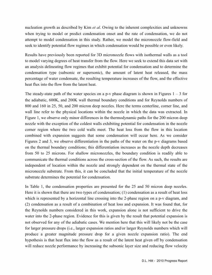
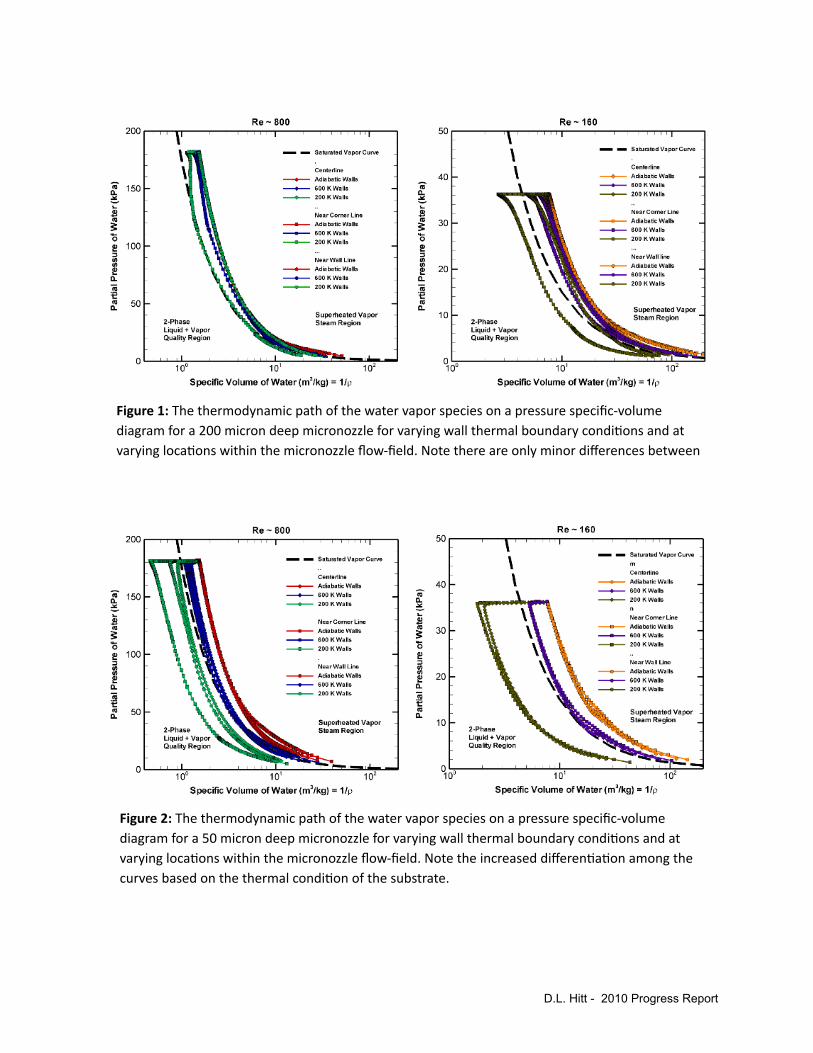
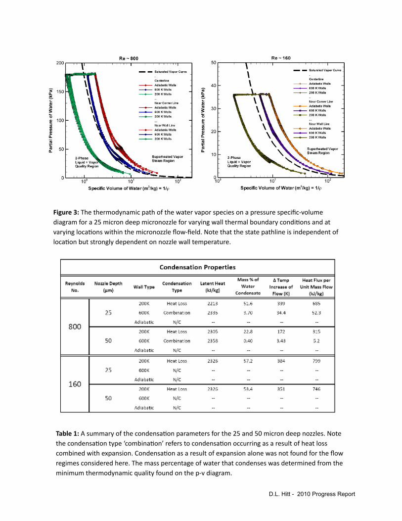
The steady-state path of the water species on a p-v phase diagram is shown in Figures 1 – 3 for the adiabatic, 600K, and 200K wall thermal boundary conditions and for Reynolds numbers of 800 and 160 in 25, 50, and 200 micron deep nozzles. Here the terms centerline, corner line, and wall line refer to the physical locations within the nozzle in which the data was extracted. In Figure 1, we observe only minor differences in the thermodynamic paths for the 200 micron deep nozzle with the exception of the coldest walls exhibiting potential for condensation in the nozzle corner region where the two cold walls meet. The heat loss from the flow in this location combined with expansion suggests that some condensation will occur here. As we consider Figures 2 and 3, we observe differentiation in the paths of the water on the p-v diagrams based on the thermal boundary conditions; this differentiation increases as the nozzle depth decreases from 50 to 25 microns. For shallow micronozzles, the boundary condition is readily able to communicate the thermal conditions across the cross-section of the flow. As such, the results are independent of location within the nozzle and strongly dependent on the thermal state of the micronozzle substrate. From this, it can be concluded that the initial temperature of the nozzle substrate determines the potential for condensation.
In Table 1, the condensation properties are presented for the 25 and 50 micron deep nozzles. Here it is shown that there are two types of condensation; (1) condensation as a result of heat loss which is represented by a horizontal line crossing into the 2-phase region on a p-v diagram, and (2) condensation as a result of a combination of heat loss and expansion. It was found that, for the Reynolds numbers considered in this work, expansion alone is not sufficient to drive the water into the 2-phase region. Evidence for this is given by the result that potential expansion is not observed for any of the adiabatic cases. We mention here that this will likely not be the case for larger pressure drops (i.e., larger expansion ratios and/or larger Reynolds numbers which will produce a greater magnitude pressure drop for a given nozzle expansion ratio). The end hypothesis is that heat flux into the flow as a result of the latent heat given off by condensation will reduce nozzle performance by increasing the subsonic layer size and reducing flow velocity
D.L. Hitt - 2010 Progress Report

via Rayleigh flow. As such, this represents a trade-off as heat loss increases nozzle performance, as previous data suggests, but only to the point in which condensation begins.
B. 3D Transient Performance Characteristics
We next consider transient simulations of 3D micronozzles with varying depths of 25, 50, 100, and 150 microns. Simulations are based on current microvalve designs and a single thruster firing is modeled by adjusting the nozzle inlet according to a hyperbolic-tangent valve actuation profile. This is achieved by employing a time-dependent, user-defined-function (UDF) on the stagnation pressure inlet boundary condition. The valve actuation time is 0.5 ms and a systematic approach of successive reductions in time-step size yields a final solution that is insensitive to further reductions in time-step size. The temporal discretization is second-order and the time-step size is Δt = 10-5 seconds which yields 170 time-steps necessary to model the complete duty cycle which includes start-up, steady-state, and the shut-down sequence.
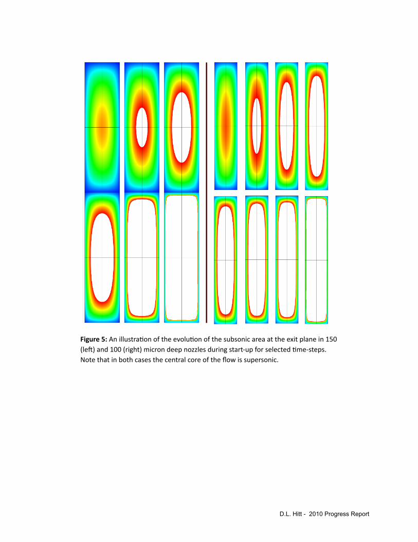
An illustration of the transient evolution of the subsonic Mach contours in a 150 micron deep nozzle is shown in Figure 4 for selected time-steps during start-up. In Figure 5, the Mach number values on the nozzle exit plane have been extracted from simulation data and the evolution of the subsonic layer on the exit plane is shown for selected time-steps during start-up in a 150 and 100 micron deep nozzle.
The subsonic layer evolution in time quantified as an area-percentage of the micronozzle exit plane is presented in Figure 6. We note here the that 25 micron deep nozzle remains subsonic throughout the entire duty cycle owing to the viscous, subsonic layers from opposing nozzle walls merging in the center of the flow. As the nozzle depth increases, the subsonic layer area-percentage decreases.
Figure 7 shows the impulse efficiency for the start-up, steady-state, and shut-down phases of the nozzle duty cycle. The phases are defined by an inlet stagnation pressure that is 99% of the steady-state inlet pressure of 250kPa and the corresponding times define the ti and tf in the efficiency equation. In Figure 8 one can see that the highest efficiency is achieved during steady-state while the lowest efficiency is found during start-up. This can be attributed to viscous forces impeding flow during start-up while viscous forces actually facilitate shut-down and prevent the occurrence of any residual thrust. In Figure 7 the total impulse per unit depth produced during a single firing is presented along with the total impulse efficiency; the quasi-1D, inviscid values are also presented. In summary, the total impulse per unit depth and impulse efficiency increase with nozzle depth and approach that of the 2D results and quasi-1D theory as the micronozzle becomes sufficiently deep.
D.L. Hitt - 2010 Progress Report
D.L. Hitt - 2010 Progress Report
Figure1:Thethermodynamicpathofthewatervaporspeciesonapressurespecific‐volumediagramfora200microndeepmicronozzleforvaryingwallthermalboundarycondi=onsandatvaryingloca=onswithinthemicronozzleflow‐field.Notethereareonlyminordifferencesbetween
Figure2:Thethermodynamicpathofthewatervaporspeciesonapressurespecific‐volumediagramfora50microndeepmicronozzleforvaryingwallthermalboundarycondi=onsandatvaryingloca=onswithinthemicronozzleflow‐field.Notetheincreaseddifferen=a=onamongthecurvesbasedonthethermalcondi=onofthesubstrate.
D.L. Hitt - 2010 Progress Report
Figure3:Thethermodynamicpathofthewatervaporspeciesonapressurespecific‐volumediagramfora25microndeepmicronozzleforvaryingwallthermalboundarycondi=onsandatvaryingloca=onswithinthemicronozzleflow‐field.Notethatthestatepathlineisindependentofloca=onbutstronglydependentonnozzlewalltemperature.
Table1:Asummaryofthecondensa=onparametersforthe25and50microndeepnozzles.Notethecondensa=ontype‘combina=on’referstocondensa=onoccurringasaresultofheatlosscombinedwithexpansion.Condensa=onasaresultofexpansionalonewasnotfoundfortheflowregimesconsideredhere.Themasspercentageofwaterthatcondenseswasdeterminedfromtheminimumthermodynamicqualityfoundonthep‐vdiagram.

D.L. Hitt - 2010 Progress Report
Figure4:Anillustra=onoftheevolu=onofthesubsonicMachcontoursina150microndeepmicronozzleduringstart‐upforselected=me‐steps.
D.L. Hitt - 2010 Progress Report
Figure5:Anillustra=onoftheevolu=onofthesubsonicareaattheexitplanein150(leL)and100(right)microndeepnozzlesduringstart‐upforselected=me‐steps.Notethatinbothcasesthecentralcoreoftheflowissupersonic.

References Cited:
Hitt, D.L. Zakrzwski C., and Thomas, M., “MEMS-based satellite micropropulsion via catalyzed hydrogen peroxide decomposition.” Smart Materials and Structures, 2001.
D.L. Hitt - 2010 Progress Report
Figure6:(LeL)Theevolu=onofthesubsonicareameasuredasapercentageofthenozzleexitplaneasafunc=onof=me.Notethatthe25microndeepnozzleremainssubsonicthroughouttheen=redutycycle.(Right)Thethrustproduc=onasafunc=onof=me.
Figure7:(LeL)Theimpulseefficiencyforthethreephasesofthemicronozzledutycycle.(Right)Thetotalimpulseperunitdepthandtheefficiencyfortheen=redutycycle.

Research Objectives & Progress for 2009-10 (Varhue)
TASK #3 - “Micro-Reactor using RuO2 Catalytic Nanostructures”
Scope. The fabrication of the Micro-Reactor is a multi-step process which must be carefully choreographed to optimize efficiency and guarantee the greatest likelihood of success. In other words, although it is simplest to repeat a single fabrication step multiple times producing multiple samples, the ability to produce a requisite number of working devices is difficult because the quality or specifications of partially fabricated parts may be insufficient to lead to a successful integrated device. To date, we have patterned a significant number of samples, i.e. Si (1” X 2”) rectangular pieces, and have etched them in a DRIE process to obtain the substrate structure for the fabrication of the micro-thruster reactor. This effort involved the following accomplishments:
• Ordering and receiving the photo-masks for the above reactor designs from Infinite Graphics.• Ordering and receiving the supplies: wafers, photo-resist and developer required to perform
the photolithographic process.• Re-establishing and in some cases repairing the equipment necessary to perform the
photolithographic process: two bake ovens, spinner and the alignment tool.• Successfully performing the photolithographic process of transferring the micro-reactor design
obtained from our design team onto the Si wafer surfaces. This effort required the development of a photolithographic process capable of withstanding an unknown etch process. Three resist/photo mask options were tried (single layer resist, double layer resist and single layer, hard mask design) and each was successful at maintaining pattern integrity, in retrospect, we were overly cautious.
The fabrication of the micro-thruster reactor requires the etching of Si material to define the channels and the catalysis support pillars. The proposed depth of the channels is 5 to 50 micron. The catalyst support pillars are approximately 5 microns across in the lateral dimension. These dimensions will require the use of an etching processes which is moderately anisotropic. Wet chemical etching is isotropic by nature and will be unable to produce the etched patterns in the Si substrate with sufficient resolution. Our plan is to prepare a good number of photoresist patterned substrates as described above, and travel to a facility where a Deep Reactive Ion Etching process can be contracted. The site where this process was obtained was the University of Maryland’s Nanotechnology Center.
!
Figure 3.1 - SEM image of RuO2 nanorods grown in the Varhue lab.
See Ref. [11] for details.
D.L. Hitt - 2010 Progress Report

Photolithographic Mask Design. The essence of the catalytic bed will be the microfabrication of an array of pillars to serve as “scaffolding” upon which catalytic nanorods (Figure 3.1) will be grown. The design of the scaffolding is motivated by a geometry previously reported by Hitt et al. in collaboration with NASA GSFC [10] . Several different configurations are being considered to optimize the decomposition of hydrogen peroxide. Several considerations were made when developing a set of possible configurations. It is important to maximize surface area for decomposition efficiency yet being careful not to impede the flow by creating excessive hydraulic resistance. Also the length of the catalyst bed is very important: if the bed is too short the fuel will not be completely decomposed; however, if it is too long the water vapor generated may condense into a liquid because of heat heat losses resulting from the large surface area to volume ratio. Thus, we have settled upon 5 different mask configurations with these points in mind. These have different pillar, gap, and channel dimensions. At each end of the channel there are reservoirs for the attachment of nano-ports to connect to external plumbing. Figure 3.2 shows one configuration with 20 micron square pillars, 40 micron gaps, and a 500 micron overall channel width. The pillars only occupy the first millimeter of the channel. The space down stream of this will allow for development of a temperature profile as a function of distance downstream of the catalytic reaction.
Figure 3.2 Mask design geometry showing overall configuration of catalytic chamber within the microchannel. The inset shows the pillar scaffolding which is only present in the initial portion of the microchannel. The staggered pillars feature square cross sections.
D.L. Hitt - 2010 Progress Report
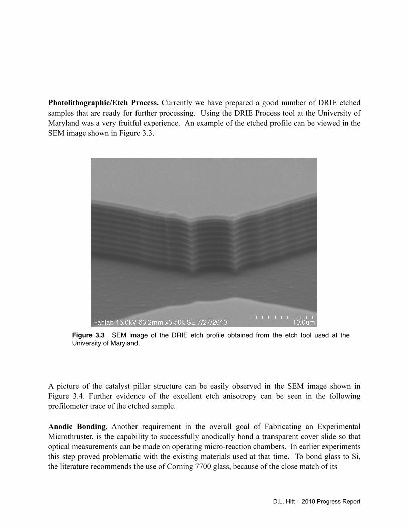
Photolithographic/Etch Process. Currently we have prepared a good number of DRIE etched samples that are ready for further processing. Using the DRIE Process tool at the University of Maryland was a very fruitful experience. An example of the etched profile can be viewed in the SEM image shown in Figure 3.3.
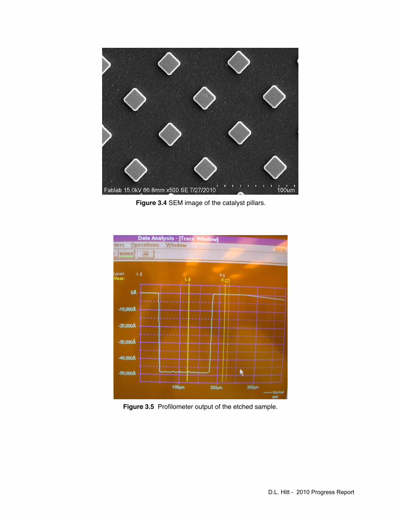
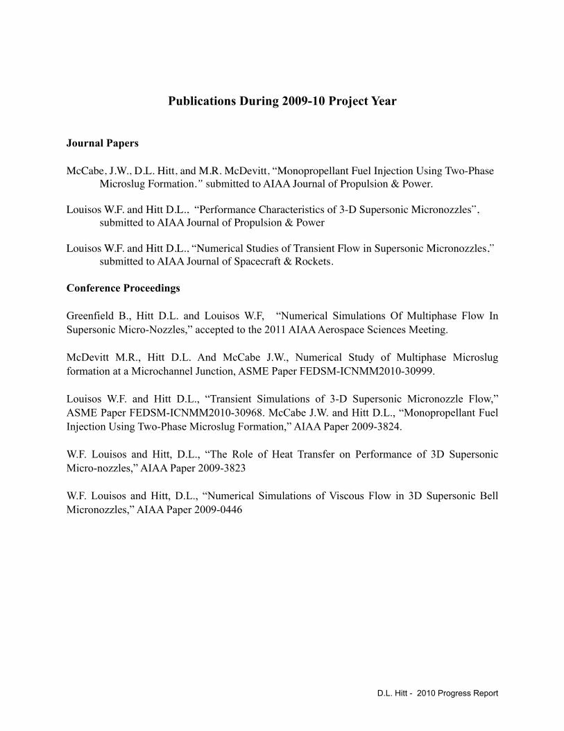
A picture of the catalyst pillar structure can be easily observed in the SEM image shown in Figure 3.4. Further evidence of the excellent etch anisotropy can be seen in the following profilometer trace of the etched sample.
Anodic Bonding. Another requirement in the overall goal of Fabricating an Experimental Microthruster, is the capability to successfully anodically bond a transparent cover slide so that optical measurements can be made on operating micro-reaction chambers. In earlier experiments this step proved problematic with the existing materials used at that time. To bond glass to Si, the literature recommends the use of Corning 7700 glass, because of the close match of its
D.L. Hitt - 2010 Progress Report
Figure 3.3 SEM image of the DRIE etch profile obtained from the etch tool used at the University of Maryland.
D.L. Hitt - 2010 Progress Report
Figure 3.4 SEM image of the catalyst pillars.
Figure 3.5 Profilometer output of the etched sample.

coefficient of thermal expansion to that of Si. This material was used previously, but was unsuccessful because the required electric field intensity was not reach with the available power supply and the thicker glass slides. Thinner glass slides were purchased from Technical Glass Products and proved to be successful. There were still problems with the inclusion of gas bubble trapped between the glass and the Si layer. This was corrected by careful attention to cleanliness, dust particles and desorption of residual moisture from the surfaces prior to bonding.
Future Experimental Goals. Despite the expiration of the grant cycle, we will continue forward with this experimental initiative. With the progress made in this final year we are now in a good position to begin constructing prototypes for testing in the Fall of 2010 as originally laid out in the project goals.
D.L. Hitt - 2010 Progress Report
Publications During 2009-10 Project Year
Journal Papers
McCabe, J.W., D.L. Hitt, and M.R. McDevitt, “Monopropellant Fuel Injection Using Two-Phase Microslug Formation.” submitted to AIAA Journal of Propulsion & Power.
Louisos W.F. and Hitt D.L., “Performance Characteristics of 3-D Supersonic Micronozzles”, submitted to AIAA Journal of Propulsion & Power
Louisos W.F. and Hitt D.L., “Numerical Studies of Transient Flow in Supersonic Micronozzles,” submitted to AIAA Journal of Spacecraft & Rockets.
Conference Proceedings
Greenfield B., Hitt D.L. and Louisos W.F, “Numerical Simulations Of Multiphase Flow In Supersonic Micro-Nozzles,” accepted to the 2011 AIAA Aerospace Sciences Meeting.
McDevitt M.R., Hitt D.L. And McCabe J.W., Numerical Study of Multiphase Microslug formation at a Microchannel Junction, ASME Paper FEDSM-ICNMM2010-30999.
Louisos W.F. and Hitt D.L., “Transient Simulations of 3-D Supersonic Micronozzle Flow,” ASME Paper FEDSM-ICNMM2010-30968. McCabe J.W. and Hitt D.L., “Monopropellant Fuel Injection Using Two-Phase Microslug Formation,” AIAA Paper 2009-3824.
W.F. Louisos and Hitt, D.L., “The Role of Heat Transfer on Performance of 3D Supersonic Micro-nozzles,” AIAA Paper 2009-3823
W.F. Louisos and Hitt, D.L., “Numerical Simulations of Viscous Flow in 3D Supersonic Bell Micronozzles,” AIAA Paper 2009-0446
D.L. Hitt - 2010 Progress Report
References Cited
1. Cubaud, T. and T.G. Mason, Capillary threads and viscous droplets in square microchannels. Physics of Fluids, 2008. 20(5): p. -.
2. Cubaud, T. and T.G. Mason, A microfluidic aquarium. Physics of Fluids, 2007. 19(9): p. -.3. Cubaud, T. and C. Ho, Transport of bubbles in square microchannels. Physics of Fluids,
2004.4. Cubaud, T., et al., Bubble dispenser in microfluidic devices. Physical Review E, 2005.5. Cubaud, T., U. Ulmanella, and C. Ho, Two-phase flow in microchannels with surface
modifications. Fluid Dynamics Research, 2006.6. Wu, M., T. Cubaud, and C. Ho, Scaling law in liquid drop coalescence driven by surface
tension. Physics of Fluids, 2004.7. McCabe, J.W., D.L. Hitt, and M.R. McDevitt, Monopropellant Fuel Injection Using Two-
Phase Microslug Formation. AIAA Journal of Propulsion & Power (submitted), 2010.8. McDevitt, M., D. Hitt, and J. McCabe. Numerical Study of Disperse, Multiphase
Microslug Formation at a Microchannel Junction. in 8th International Conference on Nanochannels, Microchannels, and Minichannels. 2010. Montreal, Canada.
9. Gray, G.F.P.a.W.G., Essentials of Multiphase Flow and Transport in Porous Media. 2008: John Wiley & Sons, Inc.
10. Hitt, D.L., C.M. Zakrzwski, and M.A. Thomas, MEMS-based satellite micropropulsion via catalyzed hydrogen peroxide decomposition. Smart Materials & Structures, 2001. 10(6): p. 1163-1175.Volmer, M. and Weber, A. “Nucleation in Supersaturated Formations,” Journal of Research in Physical Chemistry and Chemical Physics Vol. 119, 1926.
11. Wegener, P.P. ``Water Vapor Condensation Process in Supersonic Nozzles,'' Journal of Applied Physics, Vol. 25, No. 12, 1954.
12. Frank, W. “Condensation Phenomena in Supersonic Nozzles,” Acta Mechanica, Vol. 54, 1985.
13. Wyslouzil, B.E., Heath, C.H., Cheung, J.L. “Binary Condensation in a Supersonic Nozzle.” Journal of Chemical Physics, Vol 113, No. 17, November 2000.
14. Kim, Y.J., Wyslouzil, B.E., Wilemski, G., Wolk, J.,and Strey, R. “Isothermal Nucleation Rates in Supersonic Nozzles and the Properties of Small Water Clusters,” Journal of Physical Chemistry, Vol.108, No. 20, 2004.
15. Setoguchi, T., Matsuo, S., Yu, S., and Hirahara, H. “Effect of Nonequilibrium Homogenous Condensation on Flow Fields in a Supersonic Nozzle.” Journal of Thermal Science, Vol. 6, No. 2, 1997.
16. Cross, M.W., et al., Control of ruthenium oxide nanorod length in reactive sputtering. Nanotechnology, 2008. 19(4): p. 045611.
D.L. Hitt - 2010 Progress Report