Embed Size (px)
Citation preview

04-01-13
02 41 00 - 1 Project No. 437-13-111
SECTION 02 41 00
DEMOLITION
PART 1 - GENERAL
1.1 DESCRIPTION:
A. This section specifies demolition and removal of portions of buildings
and utilities.
1.2 RELATED WORK:
A. Safety Requirements: GENERAL CONDITIONS Article, ACCIDENT PREVENTION.
B. Disconnecting utility services prior to demolition: Section 01 00 00,
GENERAL REQUIREMENTS.
C. Reserved items that are to remain the property of the Government:
Section 01 00 00, GENERAL REQUIREMENTS.
D. Construction Waste Management: Section 01 74 19 CONSTRUCTION WASTE
MANAGEMENT.
E. Infection Control: Section 01 00 00, GENERAL REQUIREMENTS, INFECTION
PREVENTION MEASURES.
1.3 PROTECTION:
A. Perform demolition in such manner as to eliminate hazards to persons and
property; to minimize interference with use of adjacent areas, utilities
and structures or interruption of use of such utilities; and to provide
free passage to and from such adjacent areas of structures. Comply with
requirements of GENERAL CONDITIONS Article, ACCIDENT PREVENTION.
B. Provide safeguards, including warning signs, barricades, temporary
fences, warning lights, and other similar items that are required for
protection of all personnel during demolition and removal operations.
Comply with requirements of Section 01 00 00, GENERAL REQUIREMENTS,
Article PROTECTION OF EXISTING VEGETATION, STRUCTURES, EQUIPMENT,
UTILITIES AND IMPROVEMENTS.
C. Prevent spread of flying particles and dust. Sprinkle rubbish and debris
with water to keep dust to a minimum. Do not use water if it results in
hazardous or objectionable condition such as, but not limited to; ice,
flooding, or pollution. Vacuum and dust the work area daily.
D. In addition to previously listed fire and safety rules to be observed in
performance of work, include following:
1. Maintain at least one stairway in each structure in usable condition
to highest remaining floor. Keep stairway free of obstructions and
debris until that level of structure has been removed.
2. Wherever a cutting torch or other equipment that might cause a fire
is used, provide and maintain fire extinguishers nearby ready for
04-01-13
02 41 00 - 2 Project No. 437-13-111
immediate use. Instruct all possible users in use of fire
extinguishers.
3. Keep hydrants clear and accessible at all times. Prohibit debris from
accumulating within a radius of 4500 mm (15 feet) of fire hydrants.
E. Before beginning any demolition work, the Contractor shall survey the
site and examine the drawings and specifications to determine the extent
of the work. The contractor shall take necessary precautions to avoid
damages to existing items to remain in place, to be reused, or to remain
the property of the Medical Center; any damaged items shall be repaired
or replaced as approved by the Contracting Officer’s Representative
(COR). The Contractor shall coordinate the work of this section with all
other work. The Contractor shall ensure that structural elements are not
overloaded and shall be responsible for increasing structural supports
or adding new supports as may be required as a result of any cutting,
removal, or demolition work performed under this contract. Do not
overload structural elements. Provide new supports and reinforcement for
existing construction weakened by demolition or removal works. Repairs,
reinforcement, or structural replacement must have an approved
Structural Engineer’s design (at no additional cost to the Government)
and the COR’s approval.
F. The work shall comply with the requirements of Section 01 00 00, GENERAL
REQUIREMENTS, INFECTION PREVENTION MEASURES.
PART 2 - PRODUCTS (NOT USED)
PART 3 – EXECUTION
3.1 DEMOLITION:
A. Completely demolish and remove items as indicated in the drawings.
B. Debris, including brick, concrete, stone, metals and similar materials
shall become property of Contractor and shall be disposed of by him
daily, off the Medical Center to avoid accumulation at the demolition
site. Materials that cannot be removed daily shall be stored in areas
specified by COR. Contractor shall dispose debris in compliance with
applicable federal, state or local permits, rules and/or regulations.
C. Remove and legally dispose of all materials. Materials removed shall
become property of contractor and shall be disposed of in compliance
with applicable federal, state or local permits, rules and/or
regulations. .
3.2 CLEAN-UP:
A. On completion of work of this section and after removal of all debris,
leave site in clean condition satisfactory to COR. Clean-up shall
include off the Medical Center Property disposal of all items and
04-01-13
02 41 00 - 3 Project No. 437-13-111
materials not required to remain property of the Government as well as
all debris and rubbish resulting from demolition operations.
- - - E N D - - -

11-01-12
05 12 00 - 1 Project No. 437-13-111
SECTION 05 12 00
STRUCTURAL STEEL FRAMING
PART 1 - GENERAL
1.1 DESCRIPTION:
A. This section specifies structural steel shown and classified by Section
2, Code of Standard Practice for Steel Buildings and Bridges.
1.2 RELATED WORK:
A. Materials testing and inspection during construction: Section 01 45 29,
TESTING LABORATORY SERVICES.
B. Painting: Section 09 91 00, PAINTING.
1.3 QUALITY ASSURANCE:
A. Fabricator and erector shall maintain a program of quality assurance in
conformance with Section 8, Code of Standard Practice for Steel
Buildings and Bridges. Work shall be fabricated in an AISC certified
Category Std fabrication plant.
B. Before authorizing the commencement of steel erection, the controlling
contractor shall ensure that the steel erector is provided with the
written notification required by 29 CFR 1926.752. Provide copy of this
notification to the Project Engineer.
1.4 TOLERANCES:
A. Fabrication tolerances for structural steel shall be held within limits
established by ASTM A6, by AISC 303, Sections 6 and 7, Code of Standard
Practice for Buildings and Bridges, except as follows:
1.5 DESIGN:
A. Connections: Design and detail all connections for each member size,
steel grade and connection type to resist the loads and reactions
indicated on the drawings or specified herein. Use details consistent
with the details shown on the drawings, supplementing where necessary.
The details shown on the drawings are conceptual and do not indicate the
required weld sizes or number of bolts unless specifically noted. Use
rational engineering design and standard practice in detailing,
accounting for all loads and eccentricities in both the connection and
the members. Promptly notify the COR of any location where the
connection design criteria is not clearly indicated. The design of all
connections is subject to the review and acceptance of the Project
Engineer. Submit structural calculations prepared and sealed by a
qualified engineer registered in the state where the project is located.
Submit calculations for review before preparation of detail drawings.
1.6 REGULATORY REQUIREMENTS:
A. AISC 360: Specification for Structural Steel Buildings
11-01-12
05 12 00 - 2 Project No. 437-13-111
B. AISC 303: Code of Standard Practice for Steel Buildings and Bridges.
1.7 SUBMITTALS:
A. Submit in accordance with Section 01 33 23, SHOP DRAWINGS, PRODUCT DATA,
AND SAMPLES.
B. Shop and Erection Drawings: Complete
C. Certificates:
1. Structural steel.
2. Steel for all connections.
3. Welding materials.
4. Shop coat primer paint.
D. Test Reports:
1. Welders' qualifying tests.
E. Design Calculations and Drawings:
1. Connection calculations.
1.8 APPLICABLE PUBLICATIONS:
A. Publications listed below form a part of this specification to extent
referenced. Publications are referenced in text by basic designation
only.
B. American Institute of Steel Construction (AISC):
1. AISC 360-10 Specification for Structural Steel Buildings
3. AISC 303-10 Code of Standard Practice for Steel Buildings and Bridges
C. American National Standards Institute (ANSI):
B18.22.1-65(R2008)......Plain Washers
B18.22M-81(R2000).......Metric Plain Washers
D. American Society for Testing and Materials (ASTM):
A36/A36M-08.............Standard Specification for Carbon Structural
Steel
A53/A53M-10.............Standard Specification for Pipe, Steel, Black
and Hot-Dipped, Zinc-Coated Welded and Seamless
A123/A123M-09...........Standard Specification for Zinc (Hot-Dip
Galvanized) Coatings on Iron and Steel Products
A283/A283M-03(R2007)....Standard Specification for Low and Intermediate
Tensile Strength Carbon Steel Plates
A307-10.................Standard Specification for Carbon Steel Bolts
and Studs, 60,000 psi Tensile Strength
A325-10.................Standard Specification for Structural Bolts,
Steel, Heat Treated, 120/105 ksi Minimum Tensile
Strength
A490-12.................Standard Specification for Heat-Treated Steel
Structural Bolts 150 ksi Minimum Tensile
Strength
11-01-12
05 12 00 - 3 Project No. 437-13-111
E. American Welding Society (AWS):
D1.1/D1.1M-10...........Structural Welding Code-Steel
F. Research Council on Structural Connections (RCSC) of The Engineering
Foundation:
Specification for Structural Joints Using ASTM A325 or A490 Bolts
G. Military Specifications (Mil. Spec.):
MIL-P-21035.............Paint, High Zinc Dust Content, Galvanizing,
Repair
H. Occupational Safety and Health Administration (OSHA):
29 CFR Part 1926-2001...Safety Standards for Steel Erection
PART 2 - PRODUCTS
2.1 MATERIALS:
A. Structural Steel: ASTM A36.
B. Steel Pipe: ASTM A53, Grade B.
C. Bolts, Nuts and Washers:
1. High-strength bolts, including nuts and washers: ASTM A325.
2. Bolts and nuts, other than high-strength: ASTM A307, Grade A.
3. Plain washers, other than those in contact with high-strength bolt
heads and nuts: ANSI Standard B18.22.1.
D. Zinc Coating: ASTM A123.
E. Galvanizing Repair Paint: Mil. Spec. MIL-P-21035.
PART 3 - EXECUTION
3.1 CONNECTIONS (SHOP AND FIELD):
A. Welding: Welding in accordance with AWS D1.1. Welds shall be made only
by welders and welding operators who have been previously qualified by
tests as prescribed in AWS D1.1 to perform type of work required.
B. High-Strength Bolts: High-strength bolts tightened to a bolt tension not
less than 70% of their minimum tensile strength. Tightening done with
properly calibrated wrenches, by turn-of-nut method or by use of direct
tension indicators (bolts or washers). Tighten bolts in connections
identified as slip-critical using Direct Tension Indicators. Twist-off
torque bolts are not an acceptable alternate fastener for slip critical
connections.
3.2 FABRICATION:
A. Fabrication in accordance with Chapter M, AISC 360.
3.3 SHOP PAINTING:
A. General: Shop paint steel with primer in accordance with AISC 303,
Section 6.
B. Shop paint for steel surfaces is specified in Section 09 91 00,
PAINTING.

11-01-12
05 12 00 - 4 Project No. 437-13-111
C. Do not apply paint to following:
1. Surfaces within 50 mm (2 inches) of joints to be welded in field.
2. Top flange of members which will have shear connector studs applied.
D. Zinc Coated (Hot Dip Galvanized) per ASTM A123 (after fabrication):
Touch-up after erection: Clean and wire brush any abraded and other
spots worn through zinc coating, including threaded portions of bolts
and welds and touch-up with galvanizing repair paint.
3.4 ERECTION:
A. General: Erection in accordance with AISC 303, Section 7B. Temporary
Supports: Temporary support of structural steel frames during erection
in accordance with AISC 303, Section 7
3.5 FIELD PAINTING:
A. After erection, touch-up steel surfaces specified to be shop painted.
After welding is completed, clean and prime areas not painted due to
field welding.
B. Finish painting of steel surfaces is specified in Section 09 91 00,
PAINTING. Touch-up existing steel damaged, abraded, or chipped due to
new construction and welding operations.
- - - E N D - - -

07-01-14
05 50 00- 1 Project No. 437-13-111
SECTION 05 50 00
METAL FABRICATIONS
PART 1 - GENERAL
1.1 DESCRIPTION
A. This section specifies items and assemblies fabricated from structural
steel shapes and other materials as shown and specified.
1.2 RELATED WORK
A. Prime and finish painting: Section 09 91 00, PAINTING.
1.3 SUBMITTALS
A. Submit in accordance with Section 01 33 23, SHOP DRAWINGS, PRODUCT
DATA, AND SAMPLES.
B. Shop Drawings:
1. Each item specified, showing complete detail, location in the
project, material and size of components, method of joining various
components and assemblies, finish, and location, size and type of
anchors.
2. Mark items requiring field assembly for erection identification and
furnish erection drawings and instructions.
3. Provide templates and rough-in measurements as required.
1.4 QUALITY ASSURANCE
A. Each manufactured product shall meet, as a minimum, the requirements
specified, and shall be a standard commercial product of a manufacturer
regularly presently manufacturing items of type specified.
B. Each product type shall be the same and be made by the same
manufacturer.
C. Assembled product to the greatest extent possible before delivery to
the site.
D. Include additional features, which are not specifically prohibited by
this specification, but which are a part of the manufacturer's standard
commercial product.
1.5 APPLICABLE PUBLICATIONS
A. The publications listed below form a part of this specification to the
extent referenced. The publications are referenced in the text by the
basic designation only.
B. American Society of Mechanical Engineers (ASME):
B18.6.1-97..............Wood Screws
B18.2.2-87(R2005).......Square and Hex Nuts
C. American Society for Testing and Materials (ASTM):
07-01-14
05 50 00- 2 Project No. 437-13-111
A36/A36M-12.............Structural Steel
A53-12..................Pipe, Steel, Black and Hot-Dipped, Zinc-Coated
Welded and Seamless
A123-12.................Zinc (Hot-Dip Galvanized) Coatings on Iron and
Steel Products
F468-06(R2012)..........Nonferrous Bolts, Hex Cap Screws, Socket Head
Cap Screws and Studs for General Use
F593-13.................Stainless Steel Bolts, Hex Cap Screws, and
Studs
F1667-11................Driven Fasteners: Nails, Spikes and Staples
D. American Welding Society (AWS):
D1.1-10.................Structural Welding Code Steel
D1.3-08.................Structural Welding Code Sheet Steel
E. National Association of Architectural Metal Manufacturers (NAAMM)
AMP 500-06..............Metal Finishes Manual
F. Structural Steel Painting Council (SSPC)/Society of Protective
Coatings:
SP 1-04.................No. 1, Solvent Cleaning
SP 2-04.................No. 2, Hand Tool Cleaning
SP 3-04.................No. 3, Power Tool Cleaning
PART 2 - PRODUCTS
2.1 MATERIALS
A. Structural Steel: ASTM A36.
B. Steel Pipe: ASTM A53.
1. Galvanized for exterior locations.
2. Type S, Grade A unless specified otherwise.
3. NPS (inside diameter) as shown.
C. Primer Paint: As specified in Section 09 91 00, PAINTING.
D. Modular Channel Units:
1. Factory fabricated, channel shaped, cold formed sheet steel shapes,
complete with fittings bolts and nuts required for assembly.
2. Form channel within turned pyramid shaped clamping ridges on each
side.
3. Provide case hardened steel nuts with serrated grooves in the top
edges designed to be inserted in the channel at any point and be
given a quarter turn so as to engage the channel clamping ridges.
Provide each nut with a spring designed to hold the nut in place.
07-01-14
05 50 00- 3 Project No. 437-13-111
4. Factory finish channels and parts with oven baked primer when
exposed to view. Channels fabricated of ASTM A525, G90 galvanized
steel may have primer omitted in concealed locations. Finish screws
and nuts with zinc coating.
2.2 HARDWARE
A. Rough Hardware:
1. Furnish rough hardware with a standard plating, applied after
punching, forming and assembly of parts; galvanized, cadmium plated,
or zinc-coated by electro-galvanizing process. Galvanized G-90 where
specified.
2. Use G90 galvanized coating on ferrous metal for exterior work unless
non-ferrous metal or stainless is used.
B. Fasteners:
1. Bolts with Nuts:
a. ASME B18.2.2.
b. ASTM A307 for 415 MPa (60,000 psi) tensile strength bolts.
c. ASTM F468 for nonferrous bolts.
d. ASTM F593 for stainless steel.
2. Screws: ASME B18.6.1.
3. Washers: ASTM F436, type to suit material and anchorage.
4. Nails: ASTM F1667, Type I, style 6 or 14 for finish work.
2.3 FABRICATION GENERAL
A. Material
1. Use material as specified. Use material of commercial quality and
suitable for intended purpose for material that is not named or its
standard of quality not specified.
2. Use material free of defects which could affect the appearance or
service ability of the finished product.
B. Size:
1. Size and thickness of members as shown.
2. When size and thickness is not specified or shown for an individual
part, use size and thickness not less than that used for the same
component on similar standard commercial items or in accordance with
established shop methods.
C. Connections
1. Except as otherwise specified, connections may be made by welding,
riveting or bolting.
2. Field riveting will not be approved.
07-01-14
05 50 00- 4 Project No. 437-13-111
3. Design size, number and placement of fasteners, to develop a joint
strength of not less than the design value.
4. Holes, for rivets and bolts: Accurately punched or drilled and burrs
removed.
5. Size and shape welds to develop the full design strength of the
parts connected by welds and to transmit imposed stresses without
permanent deformation or failure when subject to service loadings.
6. Use rivets and bolts of material selected to prevent corrosion
(electrolysis) at bimetallic contacts. Plated or coated material
will not be approved.
7. Use stainless steel connectors for removable members machine screws
or bolts.
D. Fasteners and Anchors
1. Use methods for fastening or anchoring metal fabrications to
building construction as shown or specified.
2. Where fasteners and anchors are not shown, design the type, size,
location and spacing to resist the loads imposed without deformation
of the members or causing failure of the anchor or fastener, and
suit the sequence of installation.
3. Use material and finish of the fasteners compatible with the kinds
of materials which are fastened together and their location in the
finished work.
4. Fasteners for securing metal fabrications to new construction only,
may be by use of threaded or wedge type inserts or by anchors for
welding to the metal fabrication for installation before the
concrete is placed or as masonry is laid.
5. Fasteners for securing metal fabrication to existing construction or
new construction may be expansion bolts, toggle bolts, power
actuated drive pins, welding, self drilling and tapping screws or
bolts.
E. Workmanship
1. General:
a. Fabricate items to design shown.
b. Furnish members in longest lengths commercially available within
the limits shown and specified.
c. Fabricate straight, true, free from warp and twist, and where
applicable square and in same plane.
07-01-14
05 50 00- 5 Project No. 437-13-111
d. Provide holes, sinkages and reinforcement shown and required for
fasteners and anchorage items.
e. Provide openings, cut-outs, and tapped holes for attachment and
clearances required for work of other trades.
f. Prepare members for the installation and fitting of hardware.
g. Fabricate surfaces and edges free from sharp edges, burrs and
projections which may cause injury.
2. Welding:
a. Weld in accordance with AWS.
b. Welds shall show good fusion, be free from cracks and porosity
and accomplish secure and rigid joints in proper alignment.
c. Where exposed in the finished work, continuous weld for the full
length of the members joined and have depressed areas filled and
protruding welds finished smooth and flush with adjacent
surfaces.
d. Finish welded joints to match finish of adjacent surface.
3. Joining:
a. Miter or butt members at corners.
b. Where frames members are butted at corners, cut leg of frame
member perpendicular to surface, as required for clearance.
4. Cutting and Fitting:
a. Accurately cut, machine and fit joints, corners, copes, and
miters.
b. Fit removable members to be easily removed.
c. Design and construct field connections in the most practical
place for appearance and ease of installation.
d. Fit pieces together as required.
e. Fabricate connections for ease of assembly and disassembly
without use of special tools.
f. Joints firm when assembled.
g. Conceal joining, fitting and welding on exposed work as far as
practical.
h. Do not show rivets and screws prominently on the exposed face.
i. The fit of components and the alignment of holes shall eliminate
the need to modify component or to use exceptional force in the
assembly of item and eliminate the need to use other than common
tools.
F. Finish:
07-01-14
05 50 00- 6 Project No. 437-13-111
1. Finish exposed surfaces in accordance with NAAMM AMP 500 Metal
Finishes Manual.
2. Steel and Iron: NAAMM AMP 504.
a. Zinc coated (Galvanized): ASTM A123, G90 unless noted otherwise.
b. Surfaces exposed in the finished work:
1) Finish smooth rough surfaces and remove projections.
2) Fill holes, dents and similar voids and depressions with epoxy
type patching compound.
c. Shop Prime Painting:
1) Surfaces of Ferrous metal:
a) Items not specified to have other coatings.
b) Galvanized surfaces specified to have prime paint.
c) Remove all loose mill scale, rust, and paint, by hand or
power tool cleaning as defined in SSPC-SP2 and SP3.
d) Clean of oil, grease, soil and other detrimental matter by
use of solvents or cleaning compounds as defined in SSPC-
SP1.
e) After cleaning and finishing apply one coat of primer as
specified in Section 09 91 00, PAINTING.
2) Non ferrous metals: Comply with MAAMM-500 series.
G. Protection:
1. Spot prime all abraded and damaged areas of zinc coating which
expose the bare metal, using zinc rich paint on hot-dip zinc coat
items and zinc dust primer on all other zinc coated items.
2.4 SUPPORTS
A. General:
1. Fabricate ASTM A36 structural steel shapes as shown.
2. Use clip angles or make provisions for welding hangers and braces to
overhead construction.
3. Field connections may be welded or bolted.
B. For Wall Mounted Items:
1. For items supported by metal stud partitions.
2. Steel strip or hat channel minimum of 1.5 mm (0.0598 inch) thick.
3. Steel strip minimum of 150 mm (6 inches) wide, length extending one
stud space beyond end of item supported.
4. Steel hat channels where shown. Flange cut and flatted for anchorage
to stud.
07-01-14
05 50 00- 7 Project No. 437-13-111
PART 3 - EXECUTION
3.1 INSTALLATION, GENERAL
A. Set work accurately, in alignment and where shown, plumb, level, free
of rack and twist, and set parallel or perpendicular as required to
line and plane of surface.
B. Field weld in accordance with AWS.
1. Design and finish as specified for shop welding.
2. Use continuous weld unless specified otherwise.
C. Install anchoring devices and fasteners as shown and as necessary for
securing metal fabrications to building construction as specified.
Power actuated drive pins may be used except for removable items and
where members would be deformed or substrate damaged by their use.
D. Spot prime all abraded and damaged areas of zinc coating as specified
and all abraded and damaged areas of shop prime coat with same kind of
paint used for shop priming.
3.2 INSTALLATION OF SUPPORTS
A. Anchorage to structure.
1. Secure angles or channels and clips to overhead structural steel by
continuous welding unless bolting is shown.
2. Secure supports to concrete inserts by bolting or continuous welding
as shown.
3. Secure supports to mid height of concrete beams when inserts do not
exist with expansion bolts and to slabs, with expansion bolts.
unless shown otherwise.
4. Secure steel plate or hat channels to studs as detailed.
B. Supports for Wall Mounted items:
1. Locate center of support at anchorage point of supported item.
2. Locate supports where required for items shown.
3.3 CLEAN AND ADJUSTING
A. Clean after installation exposed prefinished and plated items and items
fabricated from stainless steel, aluminum and copper alloys, as
recommended by the metal manufacture and protected from damage until
completion of the project.
- - - E N D - - -

09-11
06 10 00 - 1 Project No. 437-13-111
SECTION 06 10 00
ROUGH CARPENTRY
PART 1 - GENERAL
1.1 DESCRIPTION:
A. Section specifies wood blocking and furring.
1.2 SUMBITTALS:
A. Submit in accordance with Section 01 33 23, SHOP DRAWINGS, PRODUCT DATA,
AND SAMPLES.
B. Shop Drawings showing framing connection details, fasteners, connections
and dimensions.
1.3 PRODUCT DELIVERY, STORAGE AND HANDLING:
A. Protect lumber and other products from dampness both during and after
delivery at site.
B. Pile lumber in stacks in such manner as to provide air circulation
around surfaces of each piece.
C. Stack plywood and other board products so as to prevent warping.
D. Locate stacks on well drained areas, supported at least 150 mm (6
inches) above grade and cover with well ventilated sheds having firmly
constructed over hanging roof with sufficient end wall to protect lumber
from driving rain.
1.4 APPLICABLE PUBLICATIONS:
A. Publications listed below form a part of this specification to extent
referenced. Publications are referenced in the text by basic designation
only.
B. American Society of Mechanical Engineers (ASME):
B18.2.1-96(R2005).......Square and Hex Bolts and Screws
B18.2.2-87..............Square and Hex Nuts
B18.6.1-97..............Wood Screws
B18.6.4-98(R2005).......Thread Forming and Thread Cutting Tapping Screws
and Metallic Drive Screws
C. American Society for Testing And Materials (ASTM):
A47-99(R2009)...........Ferritic Malleable Iron Castings
A48-03(R2008)...........Gray Iron Castings
A653/A653M-10...........Steel Sheet Zinc-Coated (Galvanized) or Zinc-
Iron Alloy Coated (Galvannealed) by the Hot Dip
Process
C954-10.................Steel Drill Screws for the Application of Gypsum
Board or Metal Plaster Bases to Steel Studs from
0.033 inch (2.24 mm) to 0.112-inch (2.84 mm) in
thickness

09-11
06 10 00 - 2 Project No. 437-13-111
C1002-07................Steel Self-Piercing Tapping Screws for the
Application of Gypsum Panel Products or Metal
Plaster Bases to Wood Studs or Metal Studs
D143-09.................Small Clear Specimens of Timber, Method of
Testing
D1760-01................Pressure Treatment of Timber Products
F844-07.................Washers, Steel, Plan (Flat) Unhardened for
General Use
F1667-08................Nails, Spikes, and Staples
D. Federal Specifications (Fed. Spec.):
MM-L-736C...............Lumber; Hardwood
E. Commercial Item Description (CID):
A-A-55615...............Shield, Expansion (Wood Screw and Lag Bolt Self
Threading Anchors)
F. U.S. Department of Commerce Product Standard (PS)
PS 1-95.................Construction and Industrial Plywood
PS 20-05................American Softwood Lumber Standard
PART 2 - PRODUCTS
2.1 LUMBER:
A. Unless otherwise specified, each piece of lumber bear grade mark, stamp,
or other identifying marks indicating grades of material, and rules or
standards under which produced.
1. Identifying marks in accordance with rule or standard under which
material is produced, including requirements for qualifications and
authority of the inspection organization, usage of authorized
identification, and information included in the identification.
2. Inspection agency for lumber approved by the Board of Review,
American Lumber Standards Committee, to grade species used.
B. Lumber Other Than Structural:
1. Unless otherwise specified, species graded under the grading rules of
an inspection agency approved by Board of Review, American Lumber
Standards Committee.
2. Furring, blocking, nailers and similar items 100 mm (4 inches) and
narrower Standard Grade; and, members 150 mm (6 inches) and wider,
Number 2 Grade.
C. Sizes:
1. Conforming to Prod. Std., PS20.
2. Size references are nominal sizes, unless otherwise specified, actual
sizes within manufacturing tolerances allowed by standard under which
produced.
09-11
06 10 00 - 3 Project No. 437-13-111
D. Moisture Content:
1. At time of delivery and maintained at the site.
2. Boards and lumber 50 mm (2 inches) and less in thickness: 19 percent
or less.
3. Lumber over 50 mm (2 inches) thick: 25 percent or less.
E. Fire Retardant Treatment:
1. Treatment and performance inspection, by an independent and qualified
testing agency that establishes performance ratings.
F. Preservative Treatment:
1. Treat wood members exposed to weather or in contact with plaster,
masonry or concrete, including framing of open roofed structures;
sills, sole plates, furring, and sleepers that are less than 600 mm
(24 inches) from ground; nailers, edge strips, blocking, crickets,
curbs, cant, vent strips and other members used in connection with
roofing and flashing materials.
3. Treat other members specified as preservative treated (PT).
4. Preservative treat by the pressure method complying with ASTM D1760,
except any process involving the use of Chromated Copper arsenate
(CCA) for pressure treating wood is not permitted.
2.2 ROUGH HARDWARE AND ADHESIVES:
A. Anchor Bolts:
1. ASME B18.2.1 and ANSI B18.2.2 galvanized, 13 mm (1/2 inch) unless
shown otherwise.
2. Extend at least 200 mm (8 inches) into masonry or concrete with ends
bent 50 mm (2 inches).
B. Miscellaneous Bolts: Expansion Bolts: C1D, A-A-55615; lag bolt, long
enough to extend at least 65 mm (2-1/2 inches) into masonry or concrete.
Use 13 mm (1/2 inch) bolt unless shown otherwise.
C. Washers
1. ASTM F844.
2. Use zinc or cadmium coated steel or cast iron for washers exposed to
weather.
D. Screws:
1. Wood to Wood: ANSI B18.6.1 or ASTM C1002.
2. Wood to Steel: ASTM C954, or ASTM C1002.
E. Nails:
1. Size and type best suited for purpose unless noted otherwise. Use
aluminum-alloy nails, plated nails, or zinc-coated nails, for nailing
wood work exposed to weather and on roof blocking.
2. ASTM F1667:
a. Common: Type I, Style 10.
09-11
06 10 00 - 4 Project No. 437-13-111
b. Concrete: Type I, Style 11.
c. Barbed: Type I, Style 26.
d. Underlayment: Type I, Style 25.
e. Masonry: Type I, Style 27.
f. Use special nails designed for use with ties, strap anchors,
framing connectors, joists hangers, and similar items. Nails not
less than 32 mm (1-1/4 inches) long, 8d and deformed or annular
ring shank.
PART 3 - EXECUTION
3.1 INSTALLATION OF MISCELLANEOUS WOOD MEMBERS:
A. Blocking Nailers, and Furring:
1. Install furring, blocking, nailers, and grounds where shown.
2. Use longest lengths practicable.
3. Use fire retardant treated wood blocking where shown at openings and
where shown or specified.
4. Layers of Blocking or Plates:
a. Stagger end joints between upper and lower pieces.
b. Nail at ends and not over 600 mm (24 inches) between ends.
c. Stagger nails from side to side of wood member over 125 mm (5
inches) in width.
- - - E N D - - -
06-01-12
07 21 13 - 1 Project No. 437-13-111
SECTION 07 21 13
THERMAL INSULATION
PART 1 - GENERAL
1.1 DESCRIPTION:
A. This section specifies thermal insulation for buildings.
1.2 RELATED WORK
A. Safing insulation: Section 07 84 00, FIRESTOPPING.
1.3 SUBMITTALS:
A. Submit in accordance with Section 01 33 23, SHOP DRAWINGS, PRODUCT
DATA, AND SAMPLES .
B. Manufacturer's Literature and Data:
1. Insulation, each type used
2. Adhesive, each type used.
3. Tape
C. Certificates: Stating the type, thickness and "R" value (thermal
resistance) of the insulation to be installed.
1.4 STORAGE AND HANDLING:
A. Store insulation materials in weathertight enclosure.
B. Protect insulation from damage from handling, weather and construction
operations before, during, and after installation.
1.5 APPLICABLE PUBLICATIONS:
A. The publications listed below form a part of this specification to the
extent referenced. The publications are referenced in the text by basic
designation only.
B. American Society for Testing and Materials (ASTM):
C665-06.................Mineral Fiber Blanket Thermal Insulation for
Light Frame Construction and Manufactured
Housing
PART 2 - PRODUCTS
2.1 INSULATION – GENERAL:
A. Where "R" value is not specified for insulation, use the thickness
shown on the drawings.
2.2 EXTERIOR FRAMING OR FURRING INSULATION:
A. Batt or Blanket: Optional.
B. Mineral Fiber: ASTM C665, Type II, Class C, Category I where framing is
faced with gypsum board.
C. Mineral Fiber: ASTM C665, Type III, Class A where framing is not faced
with gypsum board.

06-01-12
07 21 13 - 2 Project No. 437-13-111
PART 3 - EXECUTION
3.1 INSTALLATION - GENERAL
A. Install batt or blanket insulation with tight joints and filling
framing void completely. Seal cuts, tears, and unlapped joints with
tape.
B. Fit insulation tight against adjoining construction and penetrations,
unless specified otherwise.
- - - E N D - - -
10-11
07 53 23 - 1 Project No. 437-13-111
SECTION 07 53 23
ETHYLENE-PROPYLENE-DIENE-MONOMER ROOFING
PART 1 GENERAL
1.1 DESCRIPTION
A. Ethylene Propylene Diene Monomer (EPDM) sheet roofing adhered and
ballasted to roof deck.
1.2 RELATED WORK
A. Treated wood framing, blocking, and nailers: Section 06 10 00, ROUGH
CARPENTRY.
B. Metal cap flashings, copings, fascias, and expansion joints: Section 07
60 00, FLASHING AND SHEET METAL.
C. Mechanical equipment supports: Section 23 34 00, HVAC FANS and Section
23 31 00, HVAC DUCTS AND CASINGS, Section 23 37 00, AIR OUTLETS AND
INLETS.
1.3 QUALITY ASSURANCE
A. Approved applicator by the membrane roofing system manufacturer, and
certified by the manufacturer as having the necessary expertise to
install the specific system.
1.4 SUBMITTALS
A. Submit in accordance with Section 01 33 23, SHOP DRAWINGS, PRODUCT DATA,
AND SAMPLES.
B. Applicators approval certification by manufacturer.
1.5 DELIVERY, STORAGE AND HANDLING
A. Deliver, store, and handle materials as specified by manufacturer.
B. Store volatile materials separate from other materials with separation
to prevent fire from damaging the work, or other materials.
1.6 WARRANTY
A. Roofing work subject to the terms of the Article “Warranty of
Construction”, FAR clause 52.246-21, except extend the warranty period
to five years.
1.7 APPLICABLE PUBLICATIONS
A. Publications listed below form a part of this specification to the
extent referenced. Publications are referenced in the text by the basic
designation only.
B. American Society for Testing and Materials (ASTM):
A167-99(R2009)..........Stainless and Heat-Resisting Chromium-Nickel
Steel Plate, Sheet and Strip
B209-07.................Aluminum and Aluminum-Alloy Sheet and Plate
D751-06.................Coated Fabrics
D2103-10................Polyethylene Film and Sheeting

10-11
07 53 23 - 2 Project No. 437-13-111
D2240-05(R2010).........Rubber Property - Durometer Hardness
D3884-09................Abrasive Resistance of Textile Fabrics (Rotary
Platform, Double-Head Method)
D4637-10................EPDM Sheet Used in Single-Ply Roof Membrane
D4586-07................Asphalt Roof Cement, Asbestos Free
E96-10..................Water Vapor Transmission of Materials
E108-10.................Fire Tests of Roof Coverings
G21-09..................Resistance of Synthetic Polymeric Materials to
Fungi
C. National Roofing Contractors Association (NRCA):
Fifth Edition - 05......The NRCA Roofing and Waterproofing Manual.
D. Federal Specifications (Fed. Spec.)
FF-S-107C(2)............Screws, Tapping and Drive
FF-S-111D(1)............Screw, Wood
UU-B-790A...............Building Paper, Vegetable Fiber (Kraft,
Waterproofed, Water Repellent and Fire
Resistant)
E. Factory Mutual Engineering and Research Corporation (FM):
Annual Issue............Approval Guide Building Materials
F. Underwriters Laboratories, Inc (UL):
Annual Issue............Building Materials Directory
Annual Issue............Fire Resistance Directory
G. Warnock Hersey (WH):
Annual Issue............Certification Listings
PART 2 - PRODUCTS
2.1 EPDM SHEET ROOFING
A. Conform to ASTM D4637, Type I, Grade 1, black color; verify and match
existing.
B. Additional Properties:
PROPERTY TEST METHOD REQUIREMENT
Shore A Hardness ASTM D2240 55 to 75 Durometer
Water Vapor Permeance ASTM E96 Minimum 0.14 perms
Water Method
Fungi Resistance ASTM G21 After 21 days, no
sustained growth or
discoloration.
Fire Resistance ASTM E108
Class A
No Combustion Beyond
Flame/Heat Source
C. Thickness:
1. Use 1.5 mm (0.060-inch) thick sheet for mechanically anchored system.

10-11
07 53 23 - 3 Project No. 437-13-111
D. Pipe Boots:
1. Molded EDPM designed for flashing of round penetrations, 200 mm (8
inch) minimum height.
2. Color same as roof membrane.
2.2 EPDM FLASHING SHEET
A. Conform to ASTM D4637, Type I, Grade 1, Class U, unreinforced, color,
same as roof membrane modified as specified for flashing.
B. Self curing EPDM flashing, adaptable to irregular shapes and surfaces.
C. Minimum thickness 1.5 mm (0.060-inch).
2.3 MISCELLANEOUS ROOFING MEMBRANE MATERIALS
A. Sheet roofing manufacturers specified products.
B. Splice Adhesive: For roofing and flashing sheet.
C. Lap Sealant: Liquid EPDM rubber for roofing sheet exposed lap edge.
D. Bonding Adhesives: Neoprene, compatible with roofing membrane, flashing
membrane, insulation, metals, concrete, and masonry for bonding roofing
and flashing sheet to substrate.
E. Fastener Sealer: One part elastomeric adhesive sealant.
F. Temporary Closure Sealers (Night Sealant): Polyurethane two part sealer.
G. Primers, Splice Tapes, Cleaners, and Butyl Rubber Seals: As specified by
roof membrane manufacturer.
H. Asphalt Roof Cement: ASTM D4586.
2.4 FASTENERS
A. Pipe Compression Clamp or Drawband:
1. Stainless steel or cadmium plated steel drawband.
2. Worm drive clamp device.
B. Surface mounted base flashing clamp strip:
1. Stainless steel strip, ASTM A167, type 302 or 304, dead soft temper,
minimum 0.5 mm (0.018-inch) thick.
2. Aluminum strip: ASTM B209 24 mm (.094-inch) thick.
3. For exposed location, form strips with 6 mm (1/4 inch) wide top edge
bent out 45 degrees (for sealant) from 40 mm (1-1/2 inch) wide
material; 2400 mm (8 feet) maximum length with slotted 6 mm x 10 mm
(1/4 by 3/8-inch) holes punched at 200 mm (8 inch) centers, centered
between bend and bottom edges.
4. For locations covered by cap flashings, form strips 30 mm (1-1/4
inch) wide, 2400 mm (8 feet) maximum length with slotted holes 6 mm x
10 mm (1/4 by 3/8 inch) punched at 200 mm (8 inch) centers, centered
on strip width.
2.5 BALLAST
A. Reuse existing ballast.

10-11
07 53 23 - 4 Project No. 437-13-111
PART 3 - EXECUTION
3.1 GENERAL
A. Phased construction is not permitted. The complete installation of
roofing system is required in the same day except for area where
temporary protection is required when work is stopped. Complete
installation includes pavers and ballast for ballasted systems.
B. Dry out surfaces, including the flutes of metal deck, that become wet
from any cause during progress of the work before roofing work is
resumed.
C. Apply materials only to dry substrates.
D. Except for temporary protection specified, do not apply materials during
damp or rainy weather, during excessive wind conditions, nor while
moisture (dew, snow, fog, ice, or frost) is present in any amount in or
on the materials.
1. Do not apply materials to substrate having temperature of 4°C (40
degrees F) or less, or when materials applied with the roof require
higher application temperature.
2. Do not apply materials when the temperature is below 4°C (40 degrees
F).
E. Temporary Protection:
1. Install temporary protection consisting of a temporary seal and water
cut-offs at the end of each day's work and when work is halted for an
indefinite period or work is stopped when precipitation is imminent.
2. Temporarily seal exposed surfaces of insulation within the roofing
membrane.
3. Do not leave insulation surfaces or edges exposed.
4. Use polyethylene film or building paper to separate roof sheet from
bituminous materials.
5. Apply the temporary seal and water cut off by extending the roof
membrane beyond the insulation and securely embedding the edge of the
roof membrane in 6 mm (1/4 inch) thick by 50 mm (2 inches) wide strip
of temporary closure sealant (night sealant) and weight edge with
sandbags, to prevent displacement; space sandbags not over 2400 mm (8
foot) centers. Check daily to insure temporary seal remains
watertight. Reseal open areas and weight down.
6. Before the work resumes, cut off and discard portions of the roof
membrane in contact with roof cement or bituminous materials.
a. Cut not less than 150 mm (6 inches) back from bituminous coated
edges or surfaces.
b. Remove temporary polyethylene film or building paper.
7. Remove and discard sandbags contaminated with bituminous products.

10-11
07 53 23 - 5 Project No. 437-13-111
8. For roof areas that are to remain intact and that are subject to foot
traffic and damage, provide temporary wood walkways with notches in
sleepers to permit free drainage.
9. Provide 2 mm (6 mil) polyethylene sheeting or building paper cover
over roofing membrane under temporary wood walkways and adjacent
areas. Round all edges and corners of wood bearing on roof surface.
3.2 PREPARATION
A. Remove dirt, debris, and surface moisture. Cover or fill voids greater
than 6 mm (1/4 inch) wide to provide solid support for roof membrane.
B. Install separation sheet over bituminous material on deck surface
lapping edges and ends 150 mm (6 inches) or as recommended by roof
membrane manufacturer.
1. Do not install of separation sheet beyond what can be covered by
roofing membrane each day.
2. Use polyethylene, or building paper, that will be compatible with
seaming method.
3. Insure separation sheet completely isolates bituminous materials from
EPDM roofing membrane.
4. Turn up at penetrations, or other surfaces where bituminous materials
occur, to cover bituminous product.
5. Turn down over edges of blocking at perimeters to cover blocking.
3.3 INSTALLATION OF ROOFING AND FLASHING
A. Do not allow the membrane to come in contact with surfaces contaminated
with asphalt, coal tar, oil, grease, or other substances which are not
compatible with EPDM roofing membrane.
B. Position the membrane so it is free of buckles and wrinkles.
C. Roll sheet out on deck; inspect for defects as sheet is being rolled out
and remove defective areas:
1. Allow 30 minutes for relaxing before proceeding.
2. Lap edges and ends of sheets 75 mm (3 inches) or more as recommended
by the manufacturer. Clean lap surfaces as specified by manufacturer.
3. Adhesively splice laps. Apply pressure as required. Seam strength of
laps as required by ASTM D4637.
4. Check seams to ensure continuous adhesion and correct defects.
5. Finish edges of laps with a continuous beveled bead of lap sealant to
sheet edges to provide smooth transition as specified by
manufacturer.
6. Finish seams as the membrane is being installed (same day).
7. Anchor perimeter to deck or wall as specified.
D. Adhered System:
10-11
07 53 23 - 6 Project No. 437-13-111
1. Apply bonding adhesive in quantities required by roof membrane
manufacturer.
2. Fold sheet back on itself, clean and coat the bottom side of the
membrane and the top of the deck with adhesive. Do not coat the lap
joint area.
3. After adhesive has set according to adhesive manufacturer's
application instruction, roll the membrane into the adhesive in
manner that minimizes voids and wrinkles.
4. Repeat for other half of sheet. Cut voids and wrinkles to lay flat
and clean for repair patch over cut area.
E. Install flashings as the membrane is being installed (same day). If the
flashing cannot be completely installed in one day, complete the
installation until the flashing is in a watertight condition and provide
temporary covers or seals.
F. Installing EPDM Base Flashing and Pipe Flashing:
1. Install EPDM flashing membranes to pipes, walls or curbs to a height
not less than 200 mm (8 inches) above roof surfaces and 100 mm (4
inches) on roof membranes. Install in accordance with NRCA manual:
a. Adhere flashing to pipe, wall or curb with bonding adhesive.
b. Form inside and outside corners of EPDM flashing membrane in
accordance with NRCA manual (Fifth Edition). Form pipe flashing in
accordance with NRCA manual (Fifth Edition).
c. Lap ends not less than 100 mm (4 inches).
d. Adhesively splice flashing membranes together and flashing
membranes to roof membranes. Finish exposed edges with sealant as
specified.
2. Anchor top of flashing to walls or curbs with fasteners spaced not
over 150 mm (6 inches) on center. Use surface mounted fastening strip
with sealant on ducts. Use pipe clamps on pipes or other round
penetrations.
3. Apply sealant to top edge of flashing.
G. Repairs to membrane and flashings:
1. Remove sections of EPDM sheet roofing or flashing that is creased
wrinkled or fishmouthed.
2. Cover removed areas, cuts and damaged areas with a patch extending
100 mm (4 inches) beyond damaged, cut, or removed area. Adhesively
splice to roof membrane or flashing. Finish edge of lap with sealant
as specified.
3.4 INSTALLATION OF BALLAST SYSTEM
A. Install as soon as roof membrane is laid.
10-11
07 53 23 - 7 Project No. 437-13-111
3.5 FIELD QUALITY CONTROL
A. Examine and probe seams in the membrane and flashing in the presence of
the COR and Membrane Manufacturer's Inspector.
B. Probe the edges of welded seams with a blunt tipped instrument. Use
sufficient hand pressure to detect marginal bonds, voids, skips, and
fishmouths.
C. Cut 100 mm (4 inch) wide by 300 mm (12 inch) long samples through the
seams where directed by the COR.
1. Cut one sample for every 450 m (1500 linear feet) of seams.
2. Cut the samples perpendicular to the longitudinal direction of the
seams.
3. Failure of the samples to maintain the standard of quality within a
reasonable tolerance of the approved samples will be cause for
rejection of the work.
D. Repair areas of welded seams where samples have been taken or marginal
bond voids or skips occur.
E. Repair fishmouths and wrinkles by cutting to lay flat and installing
patch over cut area extending 100 mm (4 inches) beyond cut.
- - - E N D - - -

07-01-14
07 60 00 - 1 Project No. 437-13-111
SECTION 07 60 00
FLASHING AND SHEET METAL
PART 1 - GENERAL
1.1 DESCRIPTION
A. Formed sheet metal work for wall and roof flashing are specified in
this section.
1.2 RELATED WORK
A. Joint Sealants: Section 07 92 00, JOINT SEALANTS.
1.3 APPLICABLE PUBLICATIONS
A. Publications listed below form a part of this specification to the
extent referenced. Publications are referenced in the text by the basic
designation only. Editions of applicable publications current on date
of issue of bidding documents apply unless otherwise indicated.
B. American Architectural Manufacturers Association (AAMA):
AAMA 621................Voluntary Specification for High Performance
Organic Coatings on Coil Coated Architectural
Hot Dipped Galvanized (HDG) and Zinc-Aluminum
Coated Steel Substrates
C. ASTM International (ASTM):
A653/A653M-11...........Steel Sheet Zinc-Coated (Galvanized) or Zinc
Alloy Coated (Galvanized) by the Hot- Dip
Process
D4586-07................Asphalt Roof Cement, Asbestos Free
1.4 SUBMITTALS
A. Submit in accordance with Section 01 33 23, SHOP DRAWINGS, PRODUCT
DATA, AND SAMPLES.
B. Shop Drawings: For all specified items, including:
1. Flashings
PART 2 - PRODUCTS
2.1 FLASHING AND SHEET METAL MATERIALS
A. Galvanized Sheet: ASTM, A653.
2.2 FLASHING ACCESSORIES
A. Fasteners:
07-01-14
07 60 00 - 2 Project No. 437-13-111
1. Use galvanized steel or stainless steel for galvanized steel.
2. Nails:
a. Minimum diameter for stainless steel nails: 2 mm (0.095 inch) and
annular threaded.
b. Length to provide not less than 22 mm (7/8 inch) penetration into
anchorage.
B. Sealant: As specified in Section 07 92 00, JOINT SEALANTS for exterior
locations.
C. Roof Cement: ASTM D4586.
2.3 SHEET METAL THICKNESS
A. Except as otherwise shown or specified use thickness or weight of sheet
metal as follows:
B. Thickness of galvanized steel is 24 gauge unless otherwise indicated in
drawings.
2.4 FABRICATION, GENERAL
A. Jointing:
1. Joints shall conform to following requirements:
a. Flat-lock joints shall finish not less than 19 mm (3/4 inch)
wide.
b. Lap joints subject to stress shall finish not less than 25 mm
(one inch) wide and shall be soldered and riveted.
c. Unsoldered lap joints shall finish not less than 100 mm (4
inches) wide.
2. Flat and lap joints shall be made in direction of flow.
B. Drips:
1. Form drips at lower edge of sheet metal counter-flashings (cap
flashings), by folding edge back 13 mm (1/2 inch) and bending out 45
degrees from vertical to carry water away from the wall.
2. Form drip to provide hook to engage cleat or edge strip for
fastening for not less than 19 mm (3/4 inch) loose lock where shown.
2.5 FINISHES
A. Use same finish on adjacent metal or components and exposed metal
surfaces unless specified or shown otherwise.
B. In accordance with NAAMM Metal Finishes Manual AMP 500, unless
otherwise specified.
C. Finish exposed metal surfaces as follows, unless specified otherwise:
07-01-14
07 60 00 - 3 Project No. 437-13-111
1. Steel and Galvanized Steel:
a. Manufacturer's finish:
1) Fluorocarbon Finish: AAMA 621, high performance organic
coating.
2) Color: Match existing.
PART 3 - EXECUTION
3.1 INSTALLATION
A. General:
1. Install flashing and sheet metal items as shown in Sheet Metal and
Air Conditioning Contractors National Association, Inc.,
publication, ARCHITECTURAL SHEET METAL MANUAL, except as otherwise
shown or specified.
2. Apply Sealant as specified in Section 07 92 00, JOINT SEALANTS.
3. Apply sheet metal and other flashing material to surfaces which are
smooth, sound, clean, dry and free from defects that might affect
the application.
4. Remove projections which would puncture the materials and fill holes
and depressions with material compatible with the substrate. Cover
holes or cracks in wood wider than 6 mm (1/4 inch) with sheet metal
compatible with the roofing and flashing material used.
5. Confine direct nailing of sheet metal to strips 300 mm (12 inch) or
less wide. Nail flashing along one edge only. Space nail not over
100 mm (4 inches) on center unless specified otherwise.
6. Coordinate with roofing work for the installation of metal base
flashings and other metal items having roof flanges for anchorage
and watertight installation.
7. Install flashings in conjunction with other trades so that flashings
are inserted in other materials and joined together to provide a
water tight installation.
8. Where required to prevent galvanic action between dissimilar metal
isolate the contact areas of dissimilar metal with sheet lead,
waterproof building paper, or a coat of bituminous paint.
- - - E N D - - -

10-11
07 84 00 - 1 Project No. 437-13-111
SECTION 07 84 00
FIRESTOPPING
PART 1 GENERAL
1.1 DESCRIPTION
A. Closures of openings in walls, floors, and roof decks against
penetration of flame, heat, and smoke or gases in fire resistant rated
construction.
B. Closure of openings in walls and floors against penetration of gases or
smoke.
1.2 RELATED WORK
A. Sealants and application: Section 07 92 00, JOINT SEALANTS.
1.3 SUBMITTALS
A. Submit in accordance with Section 01 33 23, SHOP DRAWINGS, PRODUCT
DATA, AND SAMPLES.
B. Manufacturers literature, data, and installation instructions for types
of firestopping and smoke stopping used.
C. List of FM, UL, or WH classification number of systems installed.
D. Certified laboratory test reports for ASTM E814 tests for systems not
listed by FM, UL, or WH proposed for use.
1.4 DELIVERY AND STORAGE
A. Deliver materials in their original unopened containers with
manufacturer’s name and product identification.
B. Store in a location providing protection from damage and exposure to
the elements.
1.5 WARRANTY
A. Firestopping work subject to the terms of the Article “Warranty of
Construction”, FAR clause 52.246-21, except extend the warranty period
to five years.
1.6 QUALITY ASSURANCE
A. FM, UL, or WH or other approved laboratory tested products will be
acceptable.
1.7 APPLICABLE PUBLICATIONS
A. Publications listed below form a part of this specification to the
extent referenced. Publications are referenced in the text by the basic
designation only.
B. American Society for Testing and Materials (ASTM):
10-11
07 84 00 - 2 Project No. 437-13-111
E84-10..................Surface Burning Characteristics of Building
Materials
E814-11.................Fire Tests of Through-Penetration Fire Stops
C. Factory Mutual Engineering and Research Corporation (FM):
Annual Issue Approval Guide Building Materials
D. Underwriters Laboratories, Inc. (UL):
Annual Issue Building Materials Directory
Annual Issue Fire Resistance Directory
1479-10.................Fire Tests of Through-Penetration Firestops
E. Warnock Hersey (WH):
Annual Issue Certification Listings
PART 2 - PRODUCTS
2.1 FIRESTOP SYSTEMS
A. Use either factory built (Firestop Devices) or field erected (through-
Penetration Firestop Systems) to form a specific building system
maintaining required integrity of the fire barrier and stop the passage
of gases or smoke.
B. Through-penetration firestop systems and firestop devices tested in
accordance with ASTM E814 or UL 1479 using the "F" or "T" rating to
maintain the same rating and integrity as the fire barrier being
sealed. "T" ratings are not required for penetrations smaller than or
equal to 100 mm (4 in) nominal pipe or 0.01 m2 (16 sq. in.) in overall
cross sectional area.
C. Products requiring heat activation to seal an opening by its
intumescence shall exhibit a demonstrated ability to function as
designed to maintain the fire barrier.
D. Firestop sealants used for firestopping or smoke sealing shall have
following properties:
1. Contain no flammable or toxic solvents.
2. Have no dangerous or flammable out gassing during the drying or
curing of products.
3. Water-resistant after drying or curing and unaffected by high
humidity, condensation or transient water exposure.
4. When used in exposed areas, shall be capable of being sanded and
finished with similar surface treatments as used on the surrounding
wall or floor surface.
10-11
07 84 00 - 3 Project No. 437-13-111
E. Firestopping system or devices used for penetrations by glass pipe,
plastic pipe or conduits, unenclosed cables, or other non-metallic
materials shall have following properties:
1. Classified for use with the particular type of penetrating material
used.
2. Penetrations containing loose electrical cables, computer data
cables, and communications cables protected using firestopping
systems that allow unrestricted cable changes without damage to the
seal.
3. Intumescent products which would expand to seal the opening and act
as fire, smoke, toxic fumes, and, water sealant.
F. Maximum flame spread of 25 and smoke development of 50 when tested in
accordance with ASTM E84.
G. FM, UL, or WH rated or tested by an approved laboratory in accordance
with ASTM E814.
H. Materials to be asbestos free.
I. Materials shall be red in color.
J. Material ID: <FR STOP>
PART 3 - EXECUTION
3.1 EXAMINATION
A. Submit product data and installation instructions, as required by
article, submittals, after an on site examination of areas to receive
firestopping.
3.2 PREPARATION
A. Remove dirt, grease, oil, loose materials, or other substances that
prevent adherence and bonding or application of the firestopping
materials.
B. Remove insulation on insulated pipe for a distance of 150 mm (six
inches) on either side of the fire rated assembly prior to applying the
firestopping materials unless the firestopping materials are tested and
approved for use on insulated pipes.
3.3 INSTALLATION
A. Do not begin work until the specified material data and installation
instructions of the proposed firestopping systems have been submitted
and approved.
B. Install firestopping systems with smoke stopping in accordance with FM,
UL, WH, or other approved system details and installation instructions.
10-11
07 84 00 - 4 Project No. 437-13-111
C. Where work will be performed at existing walls, Contractor shall be
responsible for ensuring that all penetration, new, resulting from
demo, or existing, are property firestopped. The Contractor shall have
VA COR verify seals as work is done or completed prior to ceiling tile
or systems being reinstalled.
3.4 CLEAN-UP AND ACCEPTANCE OF WORK
A. As work on each floor is completed, remove materials, litter, and
debris.
B. Do not move materials and equipment to the next-scheduled work area
until completed work is inspected and accepted by the COR.
C. Clean up spills of liquid type materials.
- - - E N D - - -

12-11
07 92 00 - 1 Project No. 437-13-111
SECTION 07 92 00
JOINT SEALANTS
PART 1 - GENERAL
1.1 DESCRIPTION:
A. Section covers all sealant and caulking materials and their
application, wherever required for complete installation of building
materials or systems.
1.2 RELATED WORK:
A. Firestopping penetrations: Section 07 84 00, FIRESTOPPING.
1.3 QUALITY CONTROL:
A. Installer Qualifications: An experienced installer who has specialized
in installing joint sealants similar in material, design, and extent to
those indicated for this Project and whose work has resulted in joint-
sealant installations with a record of successful in-service
performance.
B. Source Limitations: Obtain each type of joint sealant through one
source from a single manufacturer.
C. VOC: Acrylic latex and Silicon sealants shall have less than 50g/l VOC
content.
1.4 SUBMITTALS:
A. Submit in accordance with Section 01 33 23, SHOP DRAWINGS, PRODUCT
DATA, AND SAMPLES.
B. Manufacturer's installation instructions for each product used.
C. Cured samples of exposed sealants for each color where required to
match adjacent material.
D. Manufacturer's Literature and Data:
1. Caulking compound
2. Primers
3. Sealing compound, each type, including compatibility when different
sealants are in contact with each other.
1.5 PROJECT CONDITIONS:
A. Environmental Limitations:
1. Do not proceed with installation of joint sealants under following
conditions:
a. When ambient and substrate temperature conditions are outside
limits permitted by joint sealant manufacturer or are below 4.4 C
(40 F).
12-11
07 92 00 - 2 Project No. 437-13-111
b. When joint substrates are wet.
B. Joint-Width Conditions:
1. Do not proceed with installation of joint sealants where joint
widths are less than those allowed by joint sealant manufacturer for
applications indicated.
C. Joint-Substrate Conditions:
1. Do not proceed with installation of joint sealants until
contaminants capable of interfering with adhesion are removed from
joint substrates.
1.6 DELIVERY, HANDLING, AND STORAGE:
A. Deliver materials in manufacturers' original unopened containers, with
brand names, date of manufacture, shelf life, and material designation
clearly marked thereon.
B. Carefully handle and store to prevent inclusion of foreign materials.
C. Do not subject to sustained temperatures exceeding 32 C (90 F) or less
than 5 C (40 F).
1.7 DEFINITIONS:
A. Definitions of terms in accordance with ASTM C717 and as specified.
B. Back-up Rod: A type of sealant backing.
C. Bond Breakers: A type of sealant backing.
D. Filler: A sealant backing used behind a back-up rod.
1.8 WARRANTY:
A. Warranty exterior sealing against leaks, adhesion, and cohesive
failure, and subject to terms of "Warranty of Construction", FAR clause
52.246-21, except that warranty period shall be extended to two years.
B. General Warranty: Special warranty specified in this Article shall not
deprive Government of other rights Government may have under other
provisions of Contract Documents and shall be in addition to, and run
concurrent with, other warranties made by Contractor under requirements
of Contract Documents.
1.9 APPLICABLE PUBLICATIONS:
A. Publications listed below form a part of this specification to extent
referenced. Publications are referenced in text by basic designation
only.
B. American Society for Testing and Materials (ASTM):
C509-06.................Elastomeric Cellular Preformed Gasket and
Sealing Material.
12-11
07 92 00 - 3 Project No. 437-13-111
C612-10.................Mineral Fiber Block and Board Thermal
Insulation.
C717-10.................Standard Terminology of Building Seals and
Sealants.
C834-10.................Latex Sealants.
C919-08.................Use of Sealants in Acoustical Applications.
C920-10.................Elastomeric Joint Sealants.
C1021-08................Laboratories Engaged in Testing of Building
Sealants.
C1193-09................Standard Guide for Use of Joint Sealants.
C1330-02 (R2007)........Cylindrical Sealant Backing for Use with Cold
Liquid Applied Sealants.
D1056-07................Specification for Flexible Cellular Materials—
Sponge or Expanded Rubber.
E84-09..................Surface Burning Characteristics of Building
Materials.
C. Sealant, Waterproofing and Restoration Institute (SWRI).
The Professionals’ Guide
PART 2 - PRODUCTS
2.1 SEALANTS:
A. S-1:
1. ASTM C920, polyurethane or polysulfide.
2. Type M.
3. Class 25.
4. Grade NS.
5. Shore A hardness of 20-40
B. S-2:
1. ASTM C920, polyurethane or polysulfide.
2. Type M.
3. Class 25.
4. Grade P.
5. Shore A hardness of 25-40.
C. S-6:
1. ASTM C920, silicone, neutral cure.
2. Type S.
3. Class: Joint movement range of plus 100 percent to minus 50 percent.
4. Grade NS.
5. Shore A hardness of 15-20.

12-11
07 92 00 - 4 Project No. 437-13-111
6. Minimum elongation of 1200 percent.
D. S-9:
1. ASTM C920 silicone.
2. Type S.
3. Class 25.
4. Grade NS.
5. Shore A hardness of 25-30.
6. Non-yellowing, mildew resistant.
2.2 CAULKING COMPOUND:
A. C-1: ASTM C834, acrylic latex, paintable.
B. C-2: One component acoustical caulking, non drying, non hardening,
synthetic rubber, paintable.
2.3 COLOR:
A. Sealants used with exposed masonry shall match color of mortar joints.
B. Sealants used with unpainted concrete shall match color of adjacent
concrete.
C. Color of sealants for other locations shall be light gray or aluminum,
unless specified otherwise.
D. Caulking shall be light gray or white, unless specified otherwise.
2.4 JOINT SEALANT BACKING:
A. General: Provide sealant backings of material and type that are
nonstaining; are compatible with joint substrates, sealants, primers,
and other joint fillers; and are approved for applications indicated by
sealant manufacturer based on field experience and laboratory testing.
B. Cylindrical Sealant Backings: ASTM C1330, of type indicated below and
of size and density to control sealant depth and otherwise contribute
to producing optimum sealant performance:
1. Type C: Closed-cell material with a surface skin.
C. Elastomeric Tubing Sealant Backings: Neoprene, butyl, EPDM, or silicone
tubing complying with ASTM D1056, nonabsorbent to water and gas, and
capable of remaining resilient at temperatures down to minus 32 C
(minus 26 F). Provide products with low compression set and of size and
shape to provide a secondary seal, to control sealant depth, and
otherwise contribute to optimum sealant performance.
D. Bond-Breaker Tape: Polyethylene tape or other plastic tape recommended
by sealant manufacturer for preventing sealant from adhering to rigid,
inflexible joint-filler materials or joint surfaces at back of joint

12-11
07 92 00 - 5 Project No. 437-13-111
where such adhesion would result in sealant failure. Provide self-
adhesive tape where applicable.
2.5 FILLER:
A. Mineral fiber board: ASTM C612, Class 1.
B. Thickness same as joint width.
C. Depth to fill void completely behind back-up rod.
2.6 PRIMER:
A. As recommended by manufacturer of caulking or sealant material.
B. Stain free type.
2.7 CLEANERS-NON POUROUS SURFACES:
A. Chemical cleaners acceptable to manufacturer of sealants and sealant
backing material, free of oily residues and other substances capable of
staining or harming joint substrates and adjacent non-porous surfaces
and formulated to promote adhesion of sealant and substrates.
PART 3 - EXECUTION
3.1 INSPECTION:
A. Inspect substrate surface for bond breaker contamination and unsound
materials at adherent faces of sealant.
B. Coordinate for repair and resolution of unsound substrate materials.
C. Inspect for uniform joint widths and that dimensions are within
tolerance established by sealant manufacturer.
3.2 PREPARATIONS:
A. Prepare joints in accordance with manufacturer's instructions and SWRI.
B. Clean surfaces of joint to receive caulking or sealants leaving joint
dry to the touch, free from frost, moisture, grease, oil, wax, lacquer
paint, or other foreign matter that would tend to destroy or impair
adhesion.
1. Clean porous joint substrate surfaces by brushing, grinding, blast
cleaning, mechanical abrading, or a combination of these methods to
produce a clean, sound substrate capable of developing optimum bond
with joint sealants.
2. Remove loose particles remaining from above cleaning operations by
vacuuming or blowing out joints with oil-free compressed air. Porous
joint surfaces include the following:
a. Concrete.
b. Masonry.
c. Unglazed surfaces of ceramic tile.
3. Remove laitance and form-release agents from concrete.
12-11
07 92 00 - 6 Project No. 437-13-111
4. Clean nonporous surfaces with chemical cleaners or other means that
do not stain, harm substrates, or leave residues capable of
interfering with adhesion of joint sealants.
a. Metal.
b. Glass.
c. Porcelain enamel.
d. Glazed surfaces of ceramic tile.
C. Do not cut or damage joint edges.
D. Apply masking tape to face of surfaces adjacent to joints before
applying primers, caulking, or sealing compounds.
1. Do not leave gaps between ends of sealant backings.
2. Do not stretch, twist, puncture, or tear sealant backings.
3. Remove absorbent sealant backings that have become wet before
sealant application and replace them with dry materials.
E. Apply primer to sides of joints wherever required by compound
manufacturer's printed instructions.
1. Apply primer prior to installation of back-up rod or bond breaker
tape.
2. Use brush or other approved means that will reach all parts of
joints.
F. Take all necessary steps to prevent three sided adhesion of sealants.
3.3 BACKING INSTALLATION:
A. Install back-up material, to form joints enclosed on three sides as
required for specified depth of sealant.
B. Where deep joints occur, install filler to fill space behind the back-
up rod and position the rod at proper depth.
C. Cut fillers installed by others to proper depth for installation of
back-up rod and sealants.
D. Install back-up rod, without puncturing the material, to a uniform
depth, within plus or minus 3 mm (1/8 inch) for sealant depths
specified.
E. Where space for back-up rod does not exist, install bond breaker tape
strip at bottom (or back) of joint so sealant bonds only to two
opposing surfaces.
F. Take all necessary steps to prevent three sided adhesion of sealants.
3.4 SEALANT DEPTHS AND GEOMETRY:
A. At widths up to 6 mm (1/4 inch), sealant depth equal to width.

12-11
07 92 00 - 7 Project No. 437-13-111
B. At widths over 6 mm (1/4 inch), sealant depth 1/2 of width up to 13 mm
(1/2 inch) maximum depth at center of joint with sealant thickness at
center of joint approximately 1/2 of depth at adhesion surface.
3.5 INSTALLATION:
A. General:
1. Apply sealants and caulking only when ambient temperature is between
5 C and 38 C (40 and 100 F).
2. Do not use polysulfide base sealants where sealant may be exposed to
fumes from bituminous materials, or where water vapor in continuous
contact with cementitious materials may be present.
3. Do not use sealant type listed by manufacture as not suitable for
use in locations specified.
4. Apply caulking and sealing compound in accordance with
manufacturer's printed instructions.
5. Avoid dropping or smearing compound on adjacent surfaces.
6. Fill joints solidly with compound and finish compound smooth.
7. Tool joints to concave surface unless shown or specified otherwise.
8. Apply compounds with nozzle size to fit joint width.
9. Test sealants for compatibility with each other and substrate. Use
only compatible sealant.
B. For application of sealants, follow requirements of ASTM C1193 unless
specified otherwise.
3.6 FIELD QUALITY CONTROL:
A. Field-Adhesion Testing: Field-test joint-sealant adhesion to joint
substrates as recommended by sealant manufacturer:
1. Extent of Testing: Test completed elastomeric sealant joints as
follows:
a. Perform one test for each 300 m (1000 feet) of joint length
thereafter or one test per each floor per elevation.
B. Inspect joints for complete fill, for absence of voids, and for joint
configuration complying with specified requirements. Record results in
a field adhesion test log.
3.7 CLEANING:
A. Fresh compound accidentally smeared on adjoining surfaces: Scrape off
immediately and rub clean with a solvent as recommended by the caulking
or sealant manufacturer.
B. After filling and finishing joints, remove masking tape.

12-11
07 92 00 - 8 Project No. 437-13-111
C. Leave adjacent surfaces in a clean and unstained condition.
3.8 LOCATIONS:
A. Exterior Building Joints, Horizontal and Vertical:
1. Metal to Metal: Type S-1, S-2
2. Metal to Masonry or Stone: Type S-1
3. Masonry to Masonry or Stone: Type S-1
B. Metal Reglets and Flashings:
1. Flashings to Wall: Type S-6
2. Metal to Metal: Type S-6
C. Sanitary Joints:
1. Pipe Penetrations: Type S-9
D. Interior Caulking:
1. Typical Narrow Joint 6 mm, (1/4 inch) or less at Walls and Adjacent
Components: Types C-1 and C-2.
2. Perimeter of Doors, Windows, Access Panels which Adjoin Concrete or
Masonry Surfaces: Types C-1 and C-2.
3. Joints at Masonry Walls and Columns, Piers, Concrete Walls or
Exterior Walls: Types C-1 and C-2.
4. Exposed Isolation Joints at Top of Full Height Walls: Types C-1 and
C-2.
- - - E N D - - -
02-01-13
09 29 00 - 1 Project No. 437-13-111
SECTION 09 29 00
GYPSUM BOARD
PART 1 - GENERAL
1.1 DESCRIPTION
A. This section specifies installation and finishing of gypsum board.
1.2 RELATED WORK
A. Acoustical Sealants: Section 07 92 00, JOINT SEALANTS.
1.3 TERMINOLOGY
A. Definitions and description of terms shall be in accordance with ASTM
C11, C840, and as specified.
B. Underside of Structure Overhead: In spaces where steel trusses or bar
joists are shown, the underside of structure overhead shall be the
underside of the floor or roof construction supported by the trusses or
bar joists.
C. "Yoked": Gypsum board cut out for opening with no joint at the opening
(along door jamb or above the door).
1.4 SUBMITTALS
A. Submit in accordance with Section 01 33 23, SHOP DRAWINGS, PRODUCT DATA,
AND SAMPLES.
B. Manufacturer's Literature and Data:
1. Finishing materials.
2. Gypsum board, each type.
1.5 DELIVERY, IDENTIFICATION, HANDLING AND STORAGE
A. In accordance with the requirements of ASTM C840.
1.6 ENVIRONMENTAL CONDITIONS
A. In accordance with the requirements of ASTM C840.
1.7 APPLICABLE PUBLICATIONS
A. The publications listed below form a part of this specification to the
extent referenced. The publications are referenced in the text by the
basic designation only.
B. American Society for Testing And Materials (ASTM):
C11-08..................Terminology Relating to Gypsum and Related
Building Materials and Systems
C475-02.................Joint Compound and Joint Tape for Finishing
Gypsum Board
C840-08.................Application and Finishing of Gypsum Board
C954-07.................Steel Drill Screws for the Application of Gypsum
Board or Metal Plaster Bases to Steel Stud from
0.033 in. (0.84mm) to 0.112 in. (2.84mm) in
thickness
02-01-13
09 29 00 - 2 Project No. 437-13-111
C1002-07................Steel Self-Piercing Tapping Screws for the
Application of Gypsum Panel Products or Metal
Plaster Bases to Wood Studs or Steel Studs
C1047-05................Accessories for Gypsum Wallboard and Gypsum
Veneer Base
C1396-06................Gypsum Board
E84-08..................Surface Burning Characteristics of Building
Materials
C. Underwriters Laboratories Inc. (UL):
Latest Edition..........Fire Resistance Directory
D. Inchcape Testing Services (ITS):
Latest Editions.........Certification Listings
PART 2 - PRODUCTS
2.1 GYPSUM BOARD
A. Gypsum Board: ASTM C1396, Type X, fire rated, 16 mm (5/8 inch) thick.
Shall contain a minimum of 20 percent recycled gypsum.
B. Coreboard or Shaft Wall Liner Panels.
1. ASTM C1396, Type X, fire rated.
2. Coreboard for shaft walls 300, 400, 600 mm (12, 16, or 24 inches)
wide by required lengths 25 mm (one inch) thick with paper faces
treated to resist moisture.
C. Gypsum cores shall contain maximum percentage of post industrial
recycled gypsum content available in the area (a minimum of 95 percent
post industrial recycled gypsum content). Paper facings shall contain
100 percent post-consumer recycled paper content.
2.2 FASTENERS
A. ASTM C1002 and ASTM C840, except as otherwise specified.
B. ASTM C954, for steel studs thicker than 0.04 mm (0.33 inch).
C. Select screws of size and type recommended by the manufacturer of the
material being fastened.
D. For fire rated construction, type and size same as used in fire rating
test.
E. Clips: Zinc-coated (galvanized) steel; gypsum board manufacturer's
standard items.
2.3 FINISHING MATERIALS AND LAMINATING ADHESIVE
A. ASTM C475 and ASTM C840. Free of antifreeze, vinyl adhesives,
preservatives, biocides and other VOC. Adhesive shall contain a maximum
VOC content of 50 g/l.
02-01-13
09 29 00 - 3 Project No. 437-13-111
PART 3 - EXECUTION
3.1 INSTALLING GYPSUM BOARD
A. Coordinate installation of gypsum board with other trades and related
work.
B. Install gypsum board in accordance with ASTM C840, except as otherwise
specified.
C. Use gypsum boards in maximum practical lengths to minimize number of end
joints.
D. Bring gypsum board into contact, but do not force into place.
E. Ceilings:
1. For single-ply construction, use perpendicular application.
2. For two-ply assembles:
a. Use perpendicular application.
b. Apply face ply of gypsum board so that joints of face ply do not
occur at joints of base ply with joints over framing members.
3.2 CAVITY SHAFT WALL
A. Conform to UL Design No. U438 or FM WALL CONSTRUCTION 12-2/HR
(Nonbearing for two-hour fire rating.
B. Cut coreboard (liner) panels 25 mm (one inch) less than floor-to-ceiling
height, and erect vertically between J-runners on shaft side.
1. Where shaft walls exceed 4300 mm (14 feet) in height, position panel
end joints within upper and lower third points of wall.
2. Stagger joints top and bottom in adjacent panels.
C. Gypsum Board:
1. Two hour wall:
a. Erect base layer (backing board) vertically on finish side of wall
with end joints staggered. Fasten base layer panels to studs with
25 mm (one inch) long screws, spaced 600 mm (24 inches) on center.
b. Use laminating adhesive between plies in accordance with UL or FM
if required by fire test.
c. Apply face layer of gypsum board required by fire test vertically
over base layer with joints staggered and attach with screws of
sufficient length to secure to framing staggered from those in
base, spaced 300 mm (12 inches) on center.
2. One hour wall with one layer on finish side of wall: Apply face layer
of gypsum board vertically. Attach to studs with screws of sufficient
length to secure to framing, spaced 300 mm (12 inches) on center in
field and along edges.
3. Where coreboard is covered with face layer of gypsum board, stagger
joints of face layer from those in the coreboard base.

02-01-13
09 29 00 - 4 Project No. 437-13-111
D. Treat joints, corners, and fasteners in face layer as specified for
finishing of gypsum board.
3.3 FINISHING OF GYPSUM BOARD
A. Finish joints, edges, corners, and fastener heads in accordance with
ASTM C840. Use Level 4 finish for al finished areas open to public view.
B. Before proceeding with installation of finishing materials, assure the
following:
1. Gypsum board is fastened and held close to framing or furring.
2. Fastening heads in gypsum board are slightly below surface in dimple
formed by driving tool.
C. Finish joints, fasteners, and all openings, including openings around
penetrations, on that part of the gypsum board extending above suspended
ceilings to seal surface of non decorated gypsum board construction.
After the installation of hanger rods, hanger wires, supports,
equipment, conduits, piping and similar work, seal remaining openings
and maintain the integrity of the construction. Sanding is not required
of non decorated surfaces.
3.4 REPAIRS
A. After taping and finishing has been completed, and before decoration,
repair all damaged and defective work, including nondecorated surfaces.
B. Patch holes or openings 13 mm (1/2 inch) or less in diameter, or
equivalent size, with a setting type finishing compound or patching
plaster.
C. Repair holes or openings over 13 mm (1/2 inch) diameter, or equivalent
size, with 16 mm (5/8 inch) thick gypsum board secured in such a manner
as to provide solid substrate equivalent to undamaged surface.
D. Tape and refinish scratched, abraded or damaged finish surfaces
including cracks and joints in non decorated surface to provide fire
protection equivalent to the rated construction.
- - - E N D - - -

10-10
09 51 00 - 1 Project No. 437-13-111
SECTION 09 51 00
ACOUSTICAL CEILINGS
PART 1- GENERAL
1.1 DESCRIPTION
A. Metal ceiling suspension system for acoustical ceilings.
B. Acoustical units.
1.2 RELATED WORK
A. Color, pattern, and location of each type of acoustical unit: Match
adjacent materials.
1.3 SUBMITTAL
A. Submit in accordance with Section 01 33 23, SHOP DRAWINGS, PRODUCT DATA,
AND SAMPLES.
B. Samples:
1. Acoustical units, each type, with label indicating conformance to
specification requirements, including units specified to match
existing.
2. Colored markers for units providing access if existing markers need
replacement.
C. Manufacturer's Literature and Data:
1. Ceiling suspension system, each type, showing complete details of
installation, including suspension system specified to match existing
and upward access system details for concealed grid systems.
2. Acoustical units, each type
D. Manufacturer's Certificates: Acoustical units, each type, in accordance
with specification requirements.
1.4 DEFINITIONS
A. Standard definitions as defined in ASTM C634.
B. Terminology as defined in ASTM E1264.
1.5 APPLICABLE PUBLICATIONS
A. Publications listed below form a part of this specification to extent
referenced. Publications are referenced in the text by basic
designation only.
B. American Society for Testing and Materials (ASTM):
A641/A641M-03...........Zinc-coated (Galvanized) Carbon Steel Wire
A653/A653M-07...........Steel Sheet, Zinc-Coated (Galvanized) or Zinc-
Iron Alloy-coated (Galvannealed) by the Hot-Dip
Process
C423-07.................Sound Absorption and Sound Absorption
Coefficients by the Reverberation Room Method
10-10
09 51 00 - 2 Project No. 437-13-111
C634-02 (E2007).........Standard Terminology Relating to Environmental
Acoustics
C635-04.................Metal Suspension Systems for Acoustical Tile and
Lay-in Panel Ceilings
C636-06.................Installation of Metal Ceiling Suspension Systems
for Acoustical Tile and Lay-in Panels
E84-07..................Surface Burning Characteristics of Building
Materials
E119-07.................Fire Tests of Building Construction and
Materials
E413-04.................Classification for Rating Sound Insulation.
E580-06.................Application of Ceiling Suspension Systems for
Acoustical Tile and Lay-in Panels in Areas
Requiring Seismic Restraint
E1264-(R2005)...........Classification for Acoustical Ceiling Products
PART 2- PRODUCTS
2.1 METAL SUSPENSION SYSTEM
A. ASTM C635, heavy-duty system, except as otherwise specified.
1. Ceiling suspension system members may be fabricated from either of
the following unless specified otherwise.
a. Extruded aluminum.
2. Use same construction for cross runners as main runners. Use of
lighter-duty sections for cross runners is not acceptable.
3. Use aluminum suspension in kitchens.
B. Exposed grid suspension system for support of lay-in panels:
1. Exposed grid width not less than 22 mm (7/8 inch) with not less than
8 mm (5/16 inch) panel bearing surface.
2. Fabricate wall molding and other special molding from the same
material with same exposed width and finish as the exposed grid
members.
3. On exposed metal surfaces apply baked-on enamel flat texture finish
in color to match adjacent acoustical units.
2.2 PERIMETER SEAL
A. Vinyl, polyethylene or polyurethane open cell sponge material having
density of 1.3 plus or minus 10 percent, compression set less than 10
percent with pressure sensitive adhesive coating on one side.
B. Thickness as required to fill voids between back of wall molding and
finish wall.
C. Not less than 9 mm (3/8 inch) wide strip.

10-10
09 51 00 - 3 Project No. 437-13-111
2.3 WIRE
A. ASTM A641.
B. For wire hangers: Minimum diameter 2.68 mm (0.1055 inch).
C. For bracing wires: Minimum diameter 3.43 mm (0.1350 inch).
2.4 ANCHORS AND INSERTS
A. Use anchors or inserts to support twice the loads imposed by hangers
attached thereto.
B. Hanger Inserts:
1. Fabricate inserts from steel, zinc-coated (galvanized after
fabrication).
2. Nailing type option for wood forms:
a. Upper portion designed for anchorage in concrete and positioning
lower portion below surface of concrete approximately 25 mm (one
inch).
b. Lower portion provided with not less than 8 mm (5/16 inch) hole to
permit attachment of hangers.
3. Flush ceiling insert type:
a. Designed to provide a shell covered opening over a wire loop to
permit attachment of hangers and keep concrete out of insert
recess.
b. Insert opening inside shell approximately 16 mm (5/8 inch) wide by
9 mm (3/8 inch) high over top of wire.
c. Wire 5 mm (3/16 inch) diameter with length to provide positive
hooked anchorage in concrete.
C. Clips:
1. Galvanized steel.
2. Designed to clamp to steel beam or bar joists, or secure framing
member together.
3. Designed to rigidly secure framing members together.
4. Designed to sustain twice the loads imposed by hangers or items
supported.
D. Tile Splines: ASTM C635.
2.5 CARRYING CHANNELS FOR SECONDARY FRAMING
A. Fabricate from cold-rolled or hot-rolled steel, black asphaltic paint
finish, free of rust. Do not use ceiling grid pieces for carrying
channels, or secondary support framing.
B. Weighing not less than the following, per 300 m (per thousand linear
feet):

10-10
09 51 00 - 4 Project No. 437-13-111
Size mm Size
Inches
Cold-rolled
Kg Pound
Hot-rolled
Kg Pound
38 1 1/2 215.4 475 508 1120
50 2 267.6 590 571.5 1260
2.6 ACOUSTICAL UNITS
A. General:
1. Ceiling Tile shall meet minimum 37% bio-based content in accordance
with USDA Bio-Preferred Product requirements.
2. ASTM E1264, weighing 3.6 kg/m2 (3/4 psf) minimum for mineral fiber
panels or tile.
3. Class A Flame Spread: ASTM 84
4. Minimum NRC (Noise Reduction Coefficient): 0.55 unless specified
otherwise: ASTM C423.
5. Minimum CAC (Ceiling Attenuation Class): 40-44 range unless specified
otherwise: ASTM E413.
6. Manufacturers standard finish, minimum Light Reflectance (LR)
coefficient of 0.75 on the exposed surfaces.
7. Lay-in panels: Size 2 feet square or 2 feet by 4 feet, with square or
reveal edges.
8. Provide an addition 25% of each type of panel for replacement of
existing damaged or stained tiles.
B. Type III Units - Mineral base with water-based painted finish less than
10 g/l VOC, Form 2 - Water felted, minimum 16 mm (5/8 inch) thick.
Mineral base to contain minimum 65 percent recycled content.
1. Basis of Design: Fissured Square Lay-in #756A by Armstrong
2. Locations: Provide in Rooms 2E-44, 2E-45, 2E-46, and 2E-48.
C. PVC Ceiling Panels: Virgin grade polyvinyl chloride (PVC), 0.76 to 0.81
mm thick.
1. Basis of Design: Genesis Printed Pro by Acoustic Ceiling Products.
2. Locations: All areas indicated to have ceiling tiles, except the
rooms noted above.
D. Legend:
1. Type I: 2x2 or 2x4 square lay-in fissured. Size to match existing.
2. Type II: 2x2 tegular lay-in fissured.
3. Type III: 2x4 square lay-in PVC panels.
2.3 ACCESS IDENTIFICATION
A. Markers:
1. Match any existing identification on replaced units.
10-10
09 51 00 - 5 Project No. 437-13-111
2. Use colored markers with pressure sensitive adhesive on one side.
3. Make colored markers of paper of plastic, 6 to 9 mm (1/4 to 3/8 inch)
in diameter.
B. Use markers of the same diameter throughout building.
C. Color Code: Use following color markers for service identification:
Color...................Service
Red.....................Sprinkler System: Valves and Controls
Green...................Domestic Water: Valves and Controls
Yellow..................Chilled Water and Heating Water
Red with white text.....Ductwork: Fire Dampers
Blue....................Ductwork: Dampers and Controls
White with black text...VAV Boxes
Black...................Gas: Laboratory, Medical, Air and Vacuum
PART 3 EXECUTION
3.1 CEILING TREATMENT
A. Lay out acoustical units so that the suspensions system falls in the
same location as existing.
B. Moldings:
1. Install metal wall molding at perimeter of room, column, or edge at
vertical surfaces.
2. Install special shaped molding at changes in ceiling heights and at
other breaks in ceiling construction to support acoustical units and
to conceal their edges.
C. Perimeter Seal:
1. Install perimeter seal between vertical leg of wall molding and
finish wall, partition, and other vertical surfaces.
2. Install perimeter seal to finish flush with exposed faces of
horizontal legs of wall molding.
3.2 CEILING SUSPENSION SYSTEM INSTALLATION
A. General:
1. Install metal suspension system for acoustical tile and lay-in panels
in accordance with ASTM C636, except as specified otherwise.
2. Use direct or indirect hung suspension system or combination thereof
as defined in ASTM C635.
3. Support a maximum area of 1.48 m2 (16 sf) of ceiling per hanger.
4. Prevent deflection in excess of 1/360 of span of cross runner and
main runner.
5. Provide extra hangers, minimum of one hanger at each corner of each
item of mechanical, electrical and miscellaneous equipment supported
by ceiling suspension system not having separate support or hangers.

10-10
09 51 00 - 6 Project No. 437-13-111
6. Provide not less than 100 mm (4 inch) clearance from the exposed face
of the acoustical units to the underside of ducts, pipe, conduit,
secondary suspension channels, concrete beams or joists; and steel
beam or bar joist unless furred system is shown,
7. Use main runners not less than 1200 mm (48 inches) in length.
8. Install hanger wires vertically. Angled wires are not acceptable
except for seismic restraint bracing wires.
B. Anchorage to Structure:
1. Steel:
a. When steel framing does not permit installation of hanger wires at
spacing required, install carrying channels for attachment of
hanger wires.
(1) Size and space carrying channels to insure that the maximum
deflection specified will not be exceeded.
(2) Attach hangers to steel carrying channels, spaced four feet on
center, unless area supported or deflection exceeds the amount
specified.
b. Attach carrying channels to the bottom flange of steel beams
spaced not 1200 mm (4 feet) on center before fire proofing is
installed. Weld or use steel clips to attach to beam to develop
full strength of carrying channel.
c. Attach hangers to bottom chord of bar joists or to carrying
channels installed between the bar joists when hanger spacing
prevents anchorage to joist. Rest carrying channels on top of the
bottom chord of the bar joists, and securely wire tie or clip to
joist.
B. Direct Hung Suspension System:
1. As illustrated in ASTM C635.
2. Support main runners by hanger wires attached directly to the
structure overhead.
3. Maximum spacing of hangers, 1200 mm (4 feet) on centers unless
interference occurs by mechanical systems. Use indirect hung
suspension system where not possible to maintain hanger spacing.
C. Indirect Hung Suspension System:
1. As illustrated in ASTM C635.
2. Space carrying channels for indirect hung suspension system not more
than 1200 mm (4 feet) on center. Space hangers for carrying channels
not more than 2400 mm (8 feet) on center or for carrying channels
less than 1200 mm (4 feet) or center so as to insure that specified
requirements are not exceeded.

10-10
09 51 00 - 7 Project No. 437-13-111
3. Support main runners by specially designed clips attached to carrying
channels.
4. Do not use ceiling grid pieces for indirect suspension system.
3.3 ACOUSTICAL UNIT INSTALLATION
A. Cut acoustic units for perimeter borders and penetrations to fit tight
against penetration for joint not concealed by molding.
B. Install lay-in acoustic panels in exposed grid with not less than 6 mm
(1/4 inch) bearing at edges on supports.
1. Install tile to lay level and in full contact with exposed grid.
2. Replace cracked, broken, stained, dirty, or tile not cut for minimum
bearing.
C. Tile in concealed grid upward access suspension system:
1. Install acoustical tile with joints close, straight and true to line,
and with exposed surfaces level and flush at joints.
2. Make corners and arises full, and without worn or broken places.
3. Locate acoustical units providing access as specified under Article,
ACCESS.
D. Markers:
1. Match any existing markers on replaced units.
2. Install markers of color code specified to identify the various
concealed piping, mechanical, and plumbing systems.
3. Attach colored markers to exposed grid.
3.4 CLEAN-UP AND COMPLETION
A. Replace damaged, discolored, dirty, cracked and broken acoustical units.
B. Leave finished work free from defects.
- - - E N D - - -

07-01-13
09 91 00 - 1 Project No. 437-13-111
SECTION 09 91 00
PAINTING
PART 1-GENERAL
1.1 DESCRIPTION
A. Section specifies field painting.
B. Section specifies prime coats which may be applied in shop under other
sections.
1.2 SUBMITTALS
A. Submit in accordance with Section 01 33 23, SHOP DRAWINGS, PRODUCT DATA,
AND SAMPLES.
B. Manufacturer's Literature and Data:
Before work is started, or sample panels are prepared, submit
manufacturer's literature, MSDS information, the current Master Painters
Institute (MPI) "Approved Product List" indicating brand label, product
name and product code as of the date of contract award, will be used to
determine compliance with the submittal requirements of this
specification. The Contractor may choose to use subsequent MPI "Approved
Product List", however, only one list may be used for the entire contract
and each coating system is to be from a single manufacturer. All coats on
a particular substrate must be from a single manufacturer. No variation
from the MPI "Approved Product List" where applicable is acceptable.
C. Sample of identity markers if used.
D. Manufacturers' Certificates indicating compliance with specified
requirements:
1. Manufacturer's paint substituted for Federal Specification paints meets
or exceeds performance of paint specified.
2. MSDS information sheets for all products.
1.3 DELIVERY AND STORAGE
A. Deliver materials to site in manufacturer's sealed container marked to
show following:
1. Name of manufacturer.
2. Product type.
3. Batch number.
4. Instructions for use.
5. Safety precautions.
6. VA project number.
7. VA project title.
8. VA contract number
B. In addition to manufacturer's label, provide a label legibly printed as
following:

07-01-13
09 91 00 - 2 Project No. 437-13-111
1. Federal Specification Number, where applicable, and name of material.
2. Surface upon which material is to be applied.
3. If paint or other coating, state coat types; prime, body or finish.
C. Maintain space for storage, and handling of painting materials and
equipment in a neat and orderly condition to prevent spontaneous
combustion from occurring or igniting adjacent items.
D. Store materials at site at least 24 hours before using, at a temperature
between 18 and 30 degrees C (65 and 85 degrees F).
1.4 APPLICABLE PUBLICATIONS
A. Publications listed below form a part of this specification to the extent
referenced. Publications are referenced in the text by basic designation
only.
B. American Conference of Governmental Industrial Hygienists (ACGIH):
ACGIH TLV-BKLT-2012.....Threshold Limit Values (TLV) for Chemical
Substances and Physical Agents and Biological
Exposure Indices (BEIs)
ACGIH TLV-DOC-2012......Documentation of Threshold Limit Values and
Biological Exposure Indices, (Seventh Edition)
C. American National Standards Institute (ANSI):
A13.1-07................Scheme for the Identification of Piping Systems
D. American Society for Testing and Materials (ASTM):
D260-86..........Boiled Linseed Oil
E. Federal Specifications (Fed Spec):
TT-P-1411A..............Paint, Copolymer-Resin, Cementitious (For
Waterproofing Concrete and Masonry Walls) (CEP)
F. Master Painters Institute (MPI):
No. 4-12................Interior/ Exterior Latex Block Filler
No. 45-12...............Interior Primer Sealer
No. 47-12...............Interior Alkyd, Semi-Gloss, MPI Gloss Level 5 (AK)
No. 50-12...............Interior Latex Primer Sealer
No. 51-12...............Interior Alkyd, Eggshell, MPI Gloss Level 3
No. 52-12...............Interior Latex, MPI Gloss Level 3 (LE)
No. 53-12...............Interior Latex, Flat, MPI Gloss Level 1 (LE)
No. 54-12...............Interior Latex, Semi-Gloss, MPI Gloss Level 5 (LE)
PART 2 - PRODUCTS
2.1 MATERIALS
A. Interior/Exterior Latex Block Filler: MPI 4.
B. Interior Primer Sealer: MPI 45.
C. Interior Alkyd, Semi-Gloss (AK): MPI 47.
D. Interior Latex Primer Sealer: MPI 50.
07-01-13
09 91 00 - 3 Project No. 437-13-111
E. Interior Alkyd, Eggshell: MPI 51
F. Interior Latex, MPI Gloss Level 3 (LE): MPI 52.
G. Interior Latex, Flat, MPI Gloss Level 1 (LE): MPI 53.
H. Interior Latex, Semi-Gloss, MPI Gloss Level 5 (LE): MPI 54.
2.2 PAINT PROPERTIES
A. Use ready-mixed (including colors), except two component epoxies,
polyurethanes, polyesters, paints having metallic powders packaged
separately and paints requiring specified additives.
B. Where no requirements are given in the referenced specifications for
primers, use primers with pigment and vehicle, compatible with substrate
and finish coats specified.
2.3 REGULATORY REQUIREMENTS/QUALITY ASSURANCE
A. Paint materials shall conform to the restrictions of the local
Environmental and Toxic Control jurisdiction.
1. Volatile Organic Compounds (VOC): VOC content of paint materials shall
not exceed 10g/l for interior latex paints/primers and 50g/l for
exterior latex paints and primers.
2. Lead-Base Paint:
a. Comply with Section 410 of the Lead-Based Paint Poisoning Prevention
Act, as amended, and with implementing regulations promulgated by
Secretary of Housing and Urban Development.
b. Regulations concerning prohibition against use of lead-based paint
in federal and federally assisted construction, or rehabilitation of
residential structures are set forth in Subpart F, Title 24, Code of
Federal Regulations, Department of Housing and Urban Development.
3. Asbestos: Materials shall not contain asbestos.
4. Chromate, Cadmium, Mercury, and Silica: Materials shall not contain
zinc-chromate, strontium-chromate, Cadmium, mercury or mercury
compounds or free crystalline silica.
5. Human Carcinogens: Materials shall not contain any of the ACGIH-BKLT
and ACGHI-DOC confirmed or suspected human carcinogens.
6. Use high performance acrylic paints in place of alkyd paints, where
possible.
7. VOC content for solvent-based paints shall not exceed 250g/l and shall
not be formulated with more than one percent aromatic hydro carbons by
weight.
PART 3 - EXECUTION
3.1 JOB CONDITIONS
A. Safety: Observe required safety regulations and manufacturer's warning and
instructions for storage, handling and application of painting materials.

07-01-13
09 91 00 - 4 Project No. 437-13-111
1. Take necessary precautions to protect personnel and property from
hazards due to falls, injuries, toxic fumes, fire, explosion, or other
harm.
2. Deposit soiled cleaning rags and waste materials in metal containers
approved for that purpose. Dispose of such items off the site at end of
each days work.
B. Atmospheric and Surface Conditions:
1. Do not apply coating when air or substrate conditions are:
a. Less than 3 degrees C (5 degrees F) above dew point.
b. Below 10 degrees C (50 degrees F) or over 35 degrees C (95 degrees
F), unless specifically pre-approved by the COR and the product
manufacturer. Under no circumstances shall application conditions
exceed manufacturer recommendations.
2. Maintain interior temperatures until paint dries hard.
3. Do no exterior painting when it is windy and dusty.
4. Do not paint in direct sunlight or on surfaces that the sun will soon
warm.
5. Apply only on clean, dry and frost free surfaces except as follows:
a. Apply water thinned acrylic and cementitious paints to damp (not
wet) surfaces where allowed by manufacturer's printed instructions.
b. Dampened with a fine mist of water on hot dry days concrete and
masonry surfaces to which water thinned acrylic and cementitious
paints are applied to prevent excessive suction and to cool surface.
3.2 SURFACE PREPARATION
A. Method of surface preparation is optional, provided results of finish
painting produce solid even color and texture specified with no overlays.
B. General:
1. Remove prefinished items not to be painted such as lighting fixtures,
escutcheon plates, hardware, trim, and similar items for reinstallation
after paint is dried.
2. Remove items for reinstallation and complete painting of such items and
adjacent areas when item or adjacent surface is not accessible or
finish is different.
3. See other sections of specifications for specified surface conditions
and prime coat.
4. Clean surfaces for painting with materials and methods compatible with
substrate and specified finish. Remove any residue remaining from
cleaning agents used. Do not use solvents, acid, or steam on concrete
and masonry.
07-01-13
09 91 00 - 5 Project No. 437-13-111
C. Ferrous Metals:
1. Remove oil, grease, soil, drawing and cutting compounds, flux and other
detrimental foreign matter in accordance with SSPC-SP 1 (Solvent
Cleaning).
2. Remove loose mill scale, rust, and paint, by hand or power tool
cleaning, as defined in SSPC-SP 2 (Hand Tool Cleaning) and SSPC-SP 3
(Power Tool Cleaning). Exception: where high temperature aluminum paint
is used, prepare surface in accordance with paint manufacturer's
instructions.
3. Fill dents, holes and similar voids and depressions in flat exposed
surfaces of hollow steel doors and frames, access panels, roll-up steel
doors and similar items specified to have semi-gloss or gloss finish
with TT-F-322D (Filler, Two-Component Type, For Dents, Small Holes and
Blow-Holes). Finish flush with adjacent surfaces.
a. This includes flat head countersunk screws used for permanent
anchors.
b. Do not fill screws of item intended for removal such as glazing
beads.
4. Spot prime abraded and damaged areas in shop prime coat which expose
bare metal with same type of paint used for prime coat. Feather edge of
spot prime to produce smooth finish coat.
5. Spot prime abraded and damaged areas which expose bare metal of factory
finished items with paint as recommended by manufacturer of item.
D. Masonry, Concrete, Cement Board, Cement Plaster and Stucco:
1. Clean and remove dust, dirt, oil, grease efflorescence, form release
agents, laitance, and other deterrents to paint adhesion.
2. Use emulsion type cleaning agents to remove oil, grease, paint and
similar products. Use of solvents, acid, or steam is not permitted.
3. Remove loose mortar in masonry work.
E. Gypsum Plaster and Gypsum Board:
1. Remove efflorescence, loose and chalking plaster or finishing
materials.
2. Remove dust, dirt, and other deterrents to paint adhesion.
3. Fill holes, cracks, and other depressions with CID-A-A-1272A [Plaster,
Gypsum (Spackling Compound) finished flush with adjacent surface, with
texture to match texture of adjacent surface. Patch holes over 25 mm
(1-inch) in diameter as specified in Section for plaster or gypsum
board.
3.3 PAINT PREPARATION
A. Thoroughly mix painting materials to ensure uniformity of color, complete
dispersion of pigment and uniform composition.
07-01-13
09 91 00 - 6 Project No. 437-13-111
B. Do not thin unless necessary for application and when finish paint is used
for body and prime coats. Use materials and quantities for thinning as
specified in manufacturer's printed instructions.
C. Remove paint skins, then strain paint through commercial paint strainer to
remove lumps and other particles.
D. Mix two component and two part paint and those requiring additives in such
a manner as to uniformly blend as specified in manufacturer's printed
instructions unless specified otherwise.
E. For tinting required to produce exact shades specified, use color pigment
recommended by the paint manufacturer.
3.4 APPLICATION
A. Start of surface preparation or painting will be construed as acceptance
of the surface as satisfactory for the application of materials.
B. Unless otherwise specified, apply paint in three coats; prime, body, and
finish. When two coats applied to prime coat are the same, first coat
applied over primer is body coat and second coat is finish coat.
C. Apply each coat evenly and cover substrate completely.
D. Allow not less than 48 hours between application of succeeding coats,
except as allowed by manufacturer's printed instructions, and approved by
COR.
E. Finish surfaces to show solid even color, free from runs, lumps,
brushmarks, laps, holidays, or other defects.
F. Apply by brush or roller.
G. Do not spray paint.
H. Do not paint in closed position operable items such as access doors and
panels, window sashes, overhead doors, and similar items except overhead
roll-up doors and shutters.
3.5 PRIME PAINTING
A. After surface preparation prime surfaces before application of body and
finish coats, except as otherwise specified.
B. Spot prime and apply body coat to damaged and abraded painted surfaces
before applying succeeding coats.
C. Additional field applied prime coats over shop or factory applied prime
coats are not required except for exterior exposed steel apply an
additional prime coat.
D. Prime rebates for stop and face glazing of wood, and for face glazing of
steel.
E. Gypsum Board:
1. Surfaces scheduled to have MPI 53 (Interior Latex, Flat), MPI Gloss
Level 1 LE)) MPI 52 (Interior Latex, MPI Gloss Level 3 (LE)) MPI 54
(Interior Latex, Semi-Gloss, MPI Gloss Level 5 (LE)) finish: Use MPI
07-01-13
09 91 00 - 7 Project No. 437-13-111
53 (Interior Latex, MPI Gloss Level 3 (LE)) MPI 52 (Interior Latex, MPI
Gloss Level 3 (LE)) MPI 54 (Interior Latex, Semi-Gloss, MPI Gloss Level
5 (LE)).
2. Primer: MPI 50(Interior Latex Primer Sealer).
F. Gypsum Plaster and Veneer Plaster:
1. MPI 45 (Interior Primer Sealer), except use MPI 50 (Interior Latex
Primer Sealer) when an alkyd flat finish is specified.
2. Surfaces scheduled to have MPI 53 (Interior Latex, Flat, MPI Gloss
Level 1 LE)) MPI 52 (Interior Latex, MPI Gloss Level 3 (LE)) MPI 54
(Interior Latex, Semi-Gloss, MPI Gloss Level 5 (LE)) finish: Use MPI 53
(Interior Latex, Flat, MPI Gloss Level 1 LE)) MPI 52 Latex, MPI Gloss
Level 3 (LE)) MPI 54 (Interior Latex, Semi-Gloss, MPI Gloss Level 5
(LE)).
G. Concrete Masonry Units except glazed or integrally colored and decorative
units:
1. MPI 4 (Block Filler) on interior surfaces.
2. Prime exterior surface as specified for exterior finishes.
H. Cement Plaster or Stucco, Concrete Masonry, Brick Masonry, and Cement
Board Interior Surfaces of Ceilings and Walls:
1. MPI 53 (Interior Latex, Flat, MPI Gloss Level 1 LE)) MPI 52 (Interior
Latex, MPI Gloss Level 3 (LE)) MPI 54 (Interior Latex, Semi-Gloss, MPI
Gloss Level 5 (LE)).
3.6 INTERIOR FINISHES
A. Apply following finish coats over prime coats in spaces or on surfaces.
B. Metal Work:
1. Apply to exposed surfaces.
2. Omit body and finish coats on surfaces concealed after installation
except electrical conduit containing conductors over 600 volts.
3. Ferrous Metal, Galvanized Metal, and Other Metals Scheduled:
a. Apply two coats of MPI 47 (Interior Alkyd, Semi-Gloss (AK)) unless
specified otherwise.
C. Gypsum Board:
1. One coat of MPI 45 (Interior Primer Sealer) plus two coats of MPI 54
(Interior Latex, Semi-Gloss, MPI Gloss Level 5 (LE)).
D. Plaster:
1. Two coats of MPI 51 (Interior Alkyd, Eggshell) (AK)).
E. Masonry and Concrete Walls:
1. Over MPI 4 (Interior/Exterior Latex Block Filler) on CMU surfaces.
2. Two coats of MPI 53 (Interior Latex, Flat, MPI Gloss Level 1 (LE)) or
MPI 52 (Interior Latex, MPI Gloss Level 3 (LE)) or MPI 54 (Interior
Latex, Semi-Gloss, MPI Gloss Level 5 (LE)).
07-01-13
09 91 00 - 8 Project No. 437-13-111
3.7 REFINISHING EXISTING PAINTED SURFACES
A. Clean, patch and repair existing surfaces as specified under surface
preparation.
B. Remove and reinstall items as specified under surface preparation.
C. Remove existing finishes or apply separation coats to prevent non
compatible coatings from having contact.
D. Patched or Replaced Areas in Surfaces and Components: Apply spot prime and
body coats as specified for new work to repaired areas or replaced
components.
E. Except where scheduled for complete painting apply finish coat over plane
surface to nearest break in plane, such as corner.
F. Refinish areas as specified for new work to match adjoining work unless
specified or scheduled otherwise.
G. Sand or dull glossy surfaces prior to painting.
H. Sand existing coatings to a feather edge so that transition between new
and existing finish will not show in finished work.
3.8 PAINT COLOR
A. Color and gloss of finish coats is to match adjacent finishes.
B. Coat Colors:
1. Color of priming coat: Lighter than body coat.
2. Color of body coat: Lighter than finish coat.
3. Color prime and body coats to not show through the finish coat and to
mask surface imperfections or contrasts.
C. Painting, Caulking, Closures, and Fillers Adjacent to Casework:
1. Paint to match color of casework where casework has a paint finish.
2. Paint to match color of wall where casework is stainless steel, plastic
laminate, or varnished wood.
3.9 MECHANICAL AND ELECTRICAL WORK FIELD PAINTING SCHEDULE
A. Field painting of mechanical and electrical consists of cleaning,
touching-up abraded shop prime coats, and applying prime, body and finish
coats to materials and equipment if not factory finished in space
scheduled to be finished.
B. Paint various systems specified in Division 23 – HEATING, VENTILATION AND
AIR-CONDITIONING, Division 26 - ELECTRICAL, and Division 27 -
COMMUNICATIONS.
C. Paint after tests have been completed.
D. Omit prime coat from factory prime-coated items.
E. Finish painting of mechanical and electrical equipment is not required
when located in interstitial spaces, above suspended ceilings, in
concealed areas such as pipe and electric closets, pipe basements, pipe
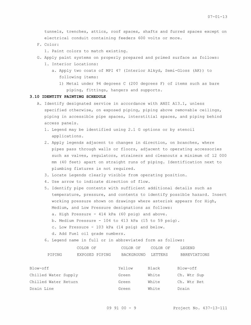
07-01-13
09 91 00 - 9 Project No. 437-13-111
tunnels, trenches, attics, roof spaces, shafts and furred spaces except on
electrical conduit containing feeders 600 volts or more.
F. Color:
1. Paint colors to match existing.
G. Apply paint systems on properly prepared and primed surface as follows:
1. Interior Locations:
a. Apply two coats of MPI 47 (Interior Alkyd, Semi-Gloss (AK)) to
following items:
1) Metal under 94 degrees C (200 degrees F) of items such as bare
piping, fittings, hangers and supports.
3.10 IDENTITY PAINTING SCHEDULE
A. Identify designated service in accordance with ANSI A13.1, unless
specified otherwise, on exposed piping, piping above removable ceilings,
piping in accessible pipe spaces, interstitial spaces, and piping behind
access panels.
1. Legend may be identified using 2.1 G options or by stencil
applications.
2. Apply legends adjacent to changes in direction, on branches, where
pipes pass through walls or floors, adjacent to operating accessories
such as valves, regulators, strainers and cleanouts a minimum of 12 000
mm (40 feet) apart on straight runs of piping. Identification next to
plumbing fixtures is not required.
3. Locate Legends clearly visible from operating position.
4. Use arrow to indicate direction of flow.
5. Identify pipe contents with sufficient additional details such as
temperature, pressure, and contents to identify possible hazard. Insert
working pressure shown on drawings where asterisk appears for High,
Medium, and Low Pressure designations as follows:
a. High Pressure - 414 kPa (60 psig) and above.
b. Medium Pressure - 104 to 413 kPa (15 to 59 psig).
c. Low Pressure - 103 kPa (14 psig) and below.
d. Add Fuel oil grade numbers.
6. Legend name in full or in abbreviated form as follows:
COLOR OF COLOR OF COLOR OF LEGEND
PIPING EXPOSED PIPING BACKGROUND LETTERS BBREVIATIONS
Blow-off Yellow Black Blow-off
Chilled Water Supply Green White Ch. Wtr Sup
Chilled Water Return Green White Ch. Wtr Ret
Drain Line Green White Drain

07-01-13
09 91 00 - 10 Project No. 437-13-111
Medium Pressure Steam Yellow Black M. P. Stm ____*
Medium Pressure Condensate Return Yellow Black M.P. Ret _____*
Low Pressure Steam Yellow Black L.P. Stm _____*
Low Pressure Condensate Return Yellow Black L.P. Ret _____*
Hot Water Heating Supply Yellow Black H. W. Htg Sup
Hot Water Heating Return Yellow Black H. W. Htg Ret
Gravity Condensate Return Yellow Black Gravity Cond Ret
Pumped Condensate Return Yellow Black Pumped Cond Ret
Fire Protection Water
Sprinkler Red White Auto Spr
Sprinkler Red White Drain
B. Fire and Smoke Partitions:
1. Identify partitions above ceilings on both sides of partitions except
within shafts in letters not less than 64 mm (2 1/2 inches) high.
2. Stenciled message: "SMOKE BARRIER" or, "FIRE BARRIER" as applicable.
3. Locate not more than 6100 mm (20 feet) on center on corridor sides of
partitions, and with a least one message per room on room side of
partition.
4. Use semigloss paint of color that contrasts with color of substrate.
C. Identify columns in pipe basements and interstitial space:
1. Apply stenciled number and letters to correspond with grid numbering
and lettering shown.
2. Paint numbers and letters 100 mm (4 inches) high, locate 450 mm (18
inches) below overhead structural slab.
3. Apply on four sides of interior columns and on inside face only of
exterior wall columns.
4. Color:
a. Use black on concrete columns.
b. Use white or contrasting color on steel columns.
3.11 PROTECTION CLEAN UP, AND TOUCH-UP
A. Protect work from paint droppings and spattering by use of masking, drop
cloths, removal of items or by other approved methods.
B. Upon completion, clean paint from hardware, glass and other surfaces and
items not required to be painted of paint drops or smears.
C. Before final inspection, touch-up or refinished in a manner to produce
solid even color and finish texture, free from defects in work which was
damaged or discolored.
- - - E N D - - -
21 00 60 - 1
SECTION 21 00 60 FIRE PROTECTION DEMOLITION
PART 1 - GENERAL
1.1 DESCRIPTION
A. This section specifies the demolition and removal of fire protection
piping, heads and accessories in existing building.
PART 2 - PRODUCTS
2.1 MATERIALS AND EQUIPMENT A. Materials and equipment for patching and extending work: As specified
in individual Sections.
PART 3 - EXECUTION
3.1 EXAMINATION
A. Verify field measurements and piping and head arrangements are as shown
on drawings.
B. Verify that abandoned equipment serve only abandoned facilities.
C. Demolition drawings are based on casual field observation and existing
record documents. The demolition drawings are diagrammatic and show the
general scope of demolition work and do not show all the construction
detail of the original record drawings. Report discrepancies to the VA
Project Engineer before disturbing existing installations.
D. The contractor shall visit the existing building and grounds and review
the existing building record drawings for details of existing
installation to familiarize himself/herself with existing conditions
prior to submitting bid. No allowance will be made subsequently, in
this connection, on behalf of the contractor for any error or negligence
on his part.
E. Beginning of demolition means the contractor accepts existing
conditions.
3.2 PREPARATION
A. Disconnect fire protection systems in areas scheduled for removal.
Notify VA Project Engineer of areas to be affected by fire protection
demolition work prior to commencing.
3.3 DEMOLITION AND EXTENSION OF EXISTING FIRE PROTECTION WORK
A. Demolish and remove from site, and extend existing fire protection work
under provisions of this division and as indicated on the drawings
unless otherwise noted.
B. Unless otherwise noted on the drawings, all salvage items removed in
connection with this contract are to become the property of the

21 00 60 - 2
contractor. Salvage items noted to remain the property of the VA shall
be delivered to a location to be designated by the VA Project Engineer.
Contractor shall remove from construction areas all trash or debris as
it accumulates and dispose of it off campus at no additional cost to the
VA. All construction areas shall be kept clean, safe, and orderly at
all times. At the completion and acceptance for work, contractor shall
remove from the site all debris and surplus materials resulting from
this work and dispose of them off campus at no additional cost to the
VA.
C. Remove, relocate, and extend existing installations to accommodate new
construction as required for proper installation and system operation.
D. Remove, relocate or provide brackets, hangers, and other accessories as
required.
E. Repair adjacent construction and finishes damaged during demolition and
extension work.
F. Maintain access to existing fire protection installations, which remain
active.
3.4 CLEANING AND REPAIR
A. Clean and repair existing materials and equipment, which remain or are
to be returned to the VA Project Engineer.
B. All building surfaces damaged and openings left by new work or the
removal or relocation of fire protection systems shall be repaired to
original condition and painted by the Contractor.
- - - E N D - - -
11-09
21 05 11 - 1
SECTION 21 05 11 COMMON WORK RESULTS FOR FIRE SUPPRESSION
PART 1 - GENERAL
1.1 DESCRIPTION
A. The requirements of this Section apply to all sections of Division 21.
B. Definitions:
1. Exposed: Piping and equipment exposed to view in finished rooms.
2. Option or optional: Contractor's choice of an alternate material or
method.
1.2 RELATED WORK
A. Section 01 00 00, GENERAL REQUIREMENTS.
B. Section 01 33 23, SHOP DRAWINGS, PRODUCT DATA, AND SAMPLES.
C. Section 07 84 00, FIRESTOPPING.
D. Section 07 92 00, JOINT SEALANTS.
E. Section 09 91 00, PAINTING.
F. Section 26 05 11, REQUIREMENTS FOR ELECTRICAL INSTALLATIONS
1.3 QUALITY ASSURANCE
A. Products Criteria:
1. Standard Products: Material and equipment shall be the standard
products of a manufacturer regularly engaged in the manufacture of
the products for at least 3 years. See other specification sections
for any exceptions.
2. Equipment Service: Products shall be supported by a service
organization which maintains a complete inventory of repair parts and
is located reasonably close to the site.
3. Multiple Units: When two or more units of materials or equipment of
the same type or class are required, these units shall be products of
one manufacturer.
4. Assembled Units: Manufacturers of equipment assemblies, which use
components made by others, assume complete responsibility for the
final assembled product.
5. Nameplates: Nameplate bearing manufacturer's name or identifiable
trademark shall be securely affixed in a conspicuous place on
equipment, or name or trademark cast integrally with equipment,
stamped or otherwise permanently marked on each item of equipment.
6. Asbestos products or equipment or materials containing asbestos shall
not be used.
B. Manufacturer's Recommendations: Where installation procedures or any
part thereof are required to be in accordance with the recommendations
11-09
21 05 11 - 2
of the manufacturer of the material being installed, printed copies of
these recommendations shall be furnished to the VA Project Engineer
prior to installation. Installation of the item will not be allowed to
proceed until the recommendations are received. Failure to furnish these
recommendations can be cause for rejection of the material.
C. Supports for sprinkler piping shall be in conformance with NFPA 13.
1.4 SUBMITTALS
A. Submit in accordance with Section 01 33 23, SHOP DRAWINGS, PRODUCT DATA,
AND SAMPLES.
B. Manufacturer's Literature and Data: Submit under the pertinent section
rather than under this section.
1. Equipment and materials identification.
2. Fire-stopping materials.
3. Hangers, inserts, supports and bracing. Provide load calculations for
variable spring and constant support hangers.
4. Wall, floor, and ceiling plates.
C. Provide detailed layout drawings of all piping systems. In addition
provide details of the following. Final drawings of installed sprinkler
systems shall be submitted to the VA in the most current version of
AutoCAD that the VA is using.
1. Hangers, inserts, supports, and bracing.
2. Pipe sleeves.
D. Maintenance Data and Operating Instructions:
1. Maintenance and operating manuals in accordance with Section 01 00
00, GENERAL REQUIREMENTS, Article, INSTRUCTIONS, for systems and
equipment.
2. Provide a listing of recommended replacement parts for keeping in
stock supply, including sources of supply, for equipment. Include in
the listing belts for equipment.
1.5 APPLICABLE PUBLICATIONS
A. The publications listed below form a part of this specification to the
extent referenced. The publications are referenced in the text by the
basic designation only.
B. American Society for Testing and Materials (ASTM):
A36/A36M-2001...........Carbon Structural Steel
A575-96.................Steel Bars, Carbon, Merchant Quality, M-Grades R
(2002)
E84-2003................Standard Test Method for Burning Characteristics
of Building Materials
11-09
21 05 11 - 3
E119-2000...............Standard Test Method for Fire Tests of Building
Construction and Materials
C. National Fire Protection Association (NFPA):
90A-96..................Installation of Air Conditioning and Ventilating
Systems
101-97..................Life Safety Code
PART 2 - PRODUCTS
2.1 EQUIPMENT AND MATERIALS IDENTIFICATION
A. Use symbols, nomenclature and equipment numbers specified, shown on the
drawings and shown in the maintenance manuals. Identification for piping
is specified in Section 09 91 00, PAINTING.
B. All exposed pipe or pipe in unfinished areas shall be painted red to
match the existing color used on sprinkler pipe currently installed at
the Fargo VA Medical Center.
2.2 FIRESTOPPING
A. Section 07 84 00, FIRESTOPPING specifies an effective barrier against
the spread of fire, smoke and gases where penetrations occur for piping.
2.3 PIPE PENETRATIONS
A. Install sleeves during construction for other than blocked out floor
openings for risers in mechanical bays.
B. Penetrations are not allowed through beams or ribs, but may be installed
in concrete beam flanges. Any deviation from this requirement must
receive prior approval of VA Project Engineer.
C. Sheet Metal, Plastic, or Moisture-Resistant Fiber Sleeves: Provide for
pipe passing through floors, interior walls, and partitions, unless
brass or steel pipe sleeves are specifically called for below.
D. Sleeve Clearance: Sleeve through floors, walls, partitions, and beam
flanges shall be one inch greater in diameter than external diameter of
pipe. Sleeve for pipe with insulation shall be large enough to
accommodate the insulation. Interior openings shall be caulked tight
with fire stopping material and sealant to prevent the spread of fire,
smoke, and gases.
2.4 TOOLS AND LUBRICANTS
A. Furnish, and turn over to the VA Project Engineer, special tools not
readily available commercially, that are required for disassembly or
adjustment of equipment and machinery furnished.
2.5 WALL, FLOOR AND CEILING PLATES
A. Material and Type: Chrome plated brass or chrome plated steel, one piece
or split type with concealed hinge, with set screw for fastening to

11-09
21 05 11 - 4
pipe, or sleeve. Use plates that fit tight around pipes, cover openings
around pipes and cover the entire pipe sleeve projection.
B. Thickness: Not less than 2.4 mm (3/32-inch) for floor plates. For wall
and ceiling plates, not less than 0.64 mm (0.025-inch) for up to 80 mm
(3-inch pipe), 0.89 mm (0.035-inch) for larger pipe.
C. Locations: Use where pipe penetrates floors, walls and ceilings in
exposed locations, in finished areas only. Use also where insulation
ends on exposed water supply pipe drop from overhead. Provide a
watertight joint in spaces where brass or steel pipe sleeves are
specified.
PART 3 - EXECUTION
3.1 INSTALLATION
A. Coordinate location of piping, sleeves, inserts, hangers, and equipment.
Locate piping, sleeves, inserts, hangers, and equipment clear of
windows, doors, openings, light outlets, and other services and
utilities. Follow manufacturer's published recommendations for
installation methods not otherwise specified.
B. Protection and Cleaning:
1. Equipment and materials shall be carefully handled, properly stored,
and adequately protected to prevent damage before and during
installation, in accordance with the manufacturer's recommendations
and as approved by the VA Project Engineer. Damaged or defective
items in the opinion of the VA Project Engineer shall be replaced.
2. Protect all finished parts of equipment, such as shafts and bearings
where accessible, from rust prior to operation by means of protective
grease coating and wrapping. Close pipe openings with caps or plugs
during installation. Tightly cover and protect equipment against
dirt, water chemical, or mechanical injury. At completion of all work
thoroughly exposed materials and equipment.
C. Install gages, valves, and other devices with due regard for ease in
reading or operating and maintaining said devices. Locate and position
gages to be easily read by operator or staff standing on floor or
walkway provided. Servicing shall not require dismantling adjacent
equipment or pipe work.
D. Work in Existing Building:
1. Perform as specified in Article, OPERATIONS AND STORAGE AREAS,
Article, ALTERATIONS, and Article, RESTORATION of the Section 01 00
00, GENERAL REQUIREMENTS for relocation of existing equipment,
alterations and restoration of existing building(s).

11-09
21 05 11 - 5
2. As specified in Section 01 00 00, GENERAL REQUIREMENTS, Article,
OPERATIONS AND STORAGE AREAS, make alterations to existing service
piping at times that will least interfere with normal operation of
the facility.
3. Cut required openings through existing masonry and reinforced
concrete using diamond core drills. Use of pneumatic hammer type
drills, impact type electric drills, and hand or manual hammer type
drills, will be permitted only with approval of the VA Project
Engineer. Locate openings that will not affect structural slabs,
columns, ribs or beams. Do not cut or drill through structural
elements.
E. Switchgear and IRM/HUB Rooms & Equipment Drip Protection: Every effort
shall be made to eliminate the installation of pipe above electrical and
telephone switchgear. If this is not possible, provide a drip pan below
the piping and provide drip pan drain to nearest floor drain.
F. All exposed pipe or pipe in unfinished areas shall be painted red to
match the existing color used on sprinkler pipe currently installed at
the Fargo VA Medical Center.
G. Inaccessible Equipment:
1. Where the Government determines that the Contractor has installed
equipment not conveniently accessible for operation and maintenance,
equipment shall be removed and reinstalled or remedial action
performed as directed at no additional cost to the Government.
2. The term "conveniently accessible" is defined as capable of being
reached without the use of ladders, or without climbing or crawling
under or over obstacles such as motors, fans, pumps, belt guards,
transformers, high voltage lines, piping, and ductwork.
3.2 LUBRICATION
A. Field check and lubricate equipment requiring lubrication prior to
initial operation.
3.3 OPERATING AND PERFORMANCE TESTS
A. Prior to the final inspection, perform required tests as specified in
Section 01 00 00, GENERAL REQUIREMENTS, Article, TESTS and submit the
test reports and records to the VA Project Engineer.
B. Should evidence of malfunction in any tested system, or piece of
equipment or component part thereof, occur during or as a result of
tests, make proper corrections, repairs or replacements, and repeat
tests at no additional cost to the Government.
- - - E N D - - -


09-11
21 10 00 - 1
SECTION 21 10 00 WATER-BASED FIRE-SUPPRESSION SYSTEMS
PART 1 - GENERAL
1.1 DESCRIPTION
A. Modification of the existing sprinkler systems as indicated on the
drawings.
B. Existing piping to be reused, replaced or removed as indicated on the
drawings. Removal of piping to include all hangers and supports.
C. Relocation of all existing sprinklers and piping in remodeled area
where required for coordination with new mechanical systems. Work to
include all necessary piping modifications, new sprinklers and new
sprinkler escutcheons.
D. Painting of exposed piping and supports to follow Section 09 91 00,
PAINTING. All exposed pipe or pipe in unfinished areas shall be painted
red to match the existing color used on sprinkler pipe currently
installed at the Fargo VA Medical Center.
1.2 RELATED WORK
A. Treatment of penetrations through rated enclosures: Section 07 84 00,
FIRESTOPPING.
B. Painting of exposed pipe: Section 09 91 00, PAINTING.
C. Section 21 05 11, COMMON WORK RESULTS FOR FIRE SUPPRESSION.
D. Section 01 33 23, SHOP DRAWINGS, PRODUCT DATA, AND SAMPLES.
1.3 DESIGN CRITERIA
A. The design, materials, equipment, installation, inspection, and testing
of the automatic sprinkler system shall be in accordance with the
required advisory provisions of NFPA 13, 14, 20, 25, 75, and 82.
1.4 QUALIFICATIONS:
A. Designer's Qualifications: Design work and shop drawings shall be
prepared by a licensed engineer practicing in the field of Fire
Protection Engineering or a NICET (National Institute for Certification
in Engineering Technologies) Level III sprinkler technician.
B. Installer's Qualifications: The installer shall possess a valid State
fire protection contractor’s license. The installer shall provide
documentation of having successfully completed three projects of
similar size and scope.
C. On-site emergency service within four hours notification.
09-11
21 10 00 - 2
1.5 SUBMITTALS
A. Submit as one package in accordance with Section 01 33 23, SHOP
DRAWINGS, PRODUCT DATA, AND SAMPLES.
B. Sprinkler design shall be done by a certified professional. All plans
shall be stamped by qualified P.E.
C. Emergency service point of contact name and 24 hour emergency telephone
number.
D. Manufacturer’s Literature and Data:
1. Pipe and fittings.
2. Drips
3. Sprinklers-each type, temperature and model
4. Pipe Hangers and Supports
1.6 AS-BUILT DOCUMENTATION
A. A Mylar as-built drawing and two blueline copies shall be provided for
each drawing. One copy of final AutoCAD drawing files shall also be
provided on CD-ROM, DVD+R, or DVD+RW.
B. Two sets of manufacturer’s literature and data updated to include
submittal review comments and any equipment substitutions. Adobe PDF
copies of the literature and data shall also be provided.
C. Two sets of operation and maintenance data updated to include submittal
review comments and any equipment substitutions including one copy of
NFPA 25. Adobe PDF copies of the operation and maintenance data shall
also be provided.
D. Manufacturers literature, reports and operation and maintenance data
shall be in a labeled 3-ring binder. PDF copies of the O&M manuals
shall also be provided.
1.7 WARRANTY
A. All work performed and materials and equipment furnished under this
contract shall be free from defects for a period of one year from date
of acceptance by the government.
B. All new piping and equipment incorporated into the new system shall be
hydrostatically tested and warranted as new.
1.8 APPLICABLE PUBLICATIONS
A. Publications listed below form a part of this specification to the
extent referenced. The publications are referenced in the text by the
basic designation only.
B. National Fire Protection Association (NFPA)
13-2010.................Installation of Sprinkler Systems

09-11
21 10 00 - 3
25-2011.................Inspection, Testing and Maintenance of water
Based Fire Protection Systems
70-2011.................National Electrical Code
72-2010.................National Fire Alarm Code
170-2009................Standards for Fire Safety Symbols
C. Underwriters Laboratories Inc. (UL)
2011....................Fire Protection Equipment Directory
D. Factory Mutual Engineering Corporation (FM)
2010....................Approval Guide
E. Contractor shall provide all necessary test equipment, parts and labor
to perform required maintenance.
F. All inspections, testing and maintenance work required by NFPA 25, NFPA
20, NFPA 13 and recommended by the equipment manufacturer shall be
provided. Work shall include operation of sprinkler system alarm and
supervisory devices.
G. Non-included Work: Maintenance service shall not include the
performance of any work due to improper use, accidents or negligence
for what the contractor is not responsible.
PART 2 - PRODUCTS
2.1 GENERAL
A. All devices and equipment shall be Underwriters Laboratories Inc.
listed for their intended purpose. All sprinklers shall be Factory
Mutual approved.
2.2 PIPING AND FITTINGS
A. Fire Protection water supply within the building up to sprinkler system
isolation valves shall be black steel, schedule 10 minimum.
B. Sprinkler piping downstream of the isolation valve on wet-pipe systems
shall be black steel, schedule 10 minimum.
C. Threaded or flanged fittings shall be ANSIB1 6.3 cast iron, class 125
minimum. Threaded fittings are not permitted on pipe with wall
thickness less than schedule 40.
D. Slip type or clamp-on type rubber gasketed fittings shall be listed for
each piping application.
E. Piping Materials Standards:
1. Ferrous piping – follow ASTM A 795 Standard
2. Welded and seamless steel pipe – follow ANSI/ASTM A 53
3. Wrought steel pipe – follow ANSI/ASME B36.10M
4. Electric resistance welded steel pipe – follow ASTM A 135
09-11
21 10 00 - 4
5. Seamless copper tube – follow ASTM B 75
6. Seamless copper water tube - follow ASTM B 88
7. Wrought seamless copper and copper alloy tube - follow ASTM B 251
8. Fluxes for soldering applications of copper and copper alloy tube –
follow ASTM B 813
9. Brazing filler metal - follow AWS A5.8
10. Solder metal, 95-5 - follow ASTM B 32
11. Alloy material - follow ASTM B 446
F. Fitting Materials Standards:
1. Cast iron threaded fitting, Class 125 and 250 - follow ASME B16.4
2. Cast iron pipe flanges and flanged fittings - follow ASME B16.1
3. Malleable iron threaded fittings, Class 150 and 300 steel - follow
ASME B16.3
4. Factory made wrought steel buttweld fittings - follow ASME B16.9
5. Buttwelding ends for pipe, valves, flanges, and fitting - follow
ASME B16.25
6. Wrought copper and copper alloy solder joint pressure fittings –
follow ASME B16.22
7. Cast copper alloy solder joint pressure fitting - follow ASME B16.18
G. Pipe Identification – All pipe, including specially listed pipe allowed
by NFPA 13, shall be marked continuously along its length by the
manufacturer in such a way as to properly identify the type of pipe.
Pipe identification shall include the manufacturer’s name, model
designation, or schedule.
H. All exposed pipe or pipe in unfinished areas shall be painted red to
match the existing color used on sprinkler pipe currently installed at
the Fargo VA Medical Center.
2.3 SPRINKLERS
A. Quick response sprinklers shall be standard type except as noted below.
The maximum distance from the deflector to finished ceiling shall be
50 mm (2 in.) for pendent sprinklers. Pendent sprinklers in finished
areas shall be provided with semi-recessed adjustable screwed
escutcheons and installed within the center one-third of their
adjustment. The sprinkler shall be installed in the flush position with
the element exposed below the ceiling line. At the specified locations,
provide the following type of sprinklers. All sprinklers except
“institutional” type sprinklers shall be FM approved. Provide quick

09-11
21 10 00 - 5
response sprinklers in all areas, except where specifically prohibited
by their listing or approval, and the following:
LOCATION TYPE
Mechanical Equipment Rooms, Electrical & Electrical Switch
Gear Rooms
Quick Response, Upright or Telephone Closets, Transformer Vaults Pendent Brass [93 °C
(200 °F)]
All Areas Not Listed Above Quick Response, Recessed Pendent, Sidewall, Chrome Plated [66-74 °C
(150-165 °F)]
B. Do not use quick response sprinklers in the same sprinkler zone with
other sprinklers types. In sprinklered light hazard patient zones that
are expanded into fully sprinklered zones, revise the existing system
to contain quick response sprinklers.
C. Sprinklers to be installed as per NFPA 13.
2.4 TOOLS AND REPLACEMENT PARTS
A. Provide any special tools or replacement parts to the owner that are
not readily available.
2.5 WALL, FLOOR AND CEILING PLATES
A. Exposed piping passing through walls, floors or ceilings shall be
provided with chrome colored escutcheon plates.
B. Comply with NFPA 101 Fire Barrier Penetration codes.
C. Firestop all walls and floor penetrations.
2.6 HANGERS
A. Hangers shall be designed to support five times the weight of the water
filled pipe plus 250 Lb (114Kg) at each point of piping support.
B. These points of support shall be adequate to support the system.
C. The spacing between hangers shall not exceed the value given for the
type of pipe as indicated in NFPA 13 tables.
D. Hanger components shall be ferrous.
E. Detailed calculations shall be submitted, when required by the
reviewing authority, showing stress developed in hangers, piping,
fittings and safety factors allowed.
PART 3 - EXECUTION
3.1 INSTALLATION
A. Drains, Test Pipes and Accessories:

09-11
21 10 00 - 6
1. Provide a drain at base of risers, drain connection on valved
sections, and drains at other locations for complete drainage of the
system. Provide valve in drain lines and connect to the central
drain riser.
2. Provide test pipes in accordance with NFPA 13. Test pipes shall be
valved and piped to discharge through proper orifice as specified
above for drains.
B. Conceal all piping, except in pipe basements, stairwells and rooms
without ceilings.
C. Install new piping and sprinklers aligned with natural building and
other sprinklers lines.
D. Locate piping in stairways as near ceiling as possible to prevent
tampering by unauthorized personnel. Provide a minimum headroom of
2250 mm (7 ft.-6 in.) for all piping.
E. Piping arrangement shall avoid contact with other piping and equipment
and allow clear access to other equipment or devices requiring access
or maintenance.
F. No other utilities (i.e. piping, ductwork, etc.) above the ceiling
shall be allowed to rest on existing or new sprinkler piping and
accessories. The contractor shall provide supports for any other
utility that touches existing or new sprinkler piping. This shall be
checked during on-site above ceiling inspections to make sure this
complies.
G. All exposed pipe or pipe in unfinished areas shall be painted red to
match the existing color used on sprinkler pipe currently installed at
the Fargo VA Medical Center.
H. Firestopping shall comply with Section 07 84 00, FIRESTOPPING. All
piping and holes through walls or floors shall be sealed on a daily
basis.
3.2 TEST
A. Automatic Sprinkler System: NFPA 13 and 25.
- - - END - - -
23 00 60 - 1
SECTION 23 00 60 HVAC DEMOLITION
PART 1 - GENERAL
1.1 DESCRIPTION
A. This section specifies the demolition and removal of diffusers,
ductwork, ductwork insulation and accessories in existing building.
PART 2 - PRODUCTS
2.1 MATERIALS AND EQUIPMENT
A. Materials and equipment for patching and extending work: As specified
in individual sections.
PART 3 - EXECUTION
3.1 EXAMINATION
A. Verify field measurements and existing ductwork arrangements are as
shown on drawings.
B. Verify that abandoned equipment serve only abandoned facilities.
C. Demolition drawings are based on casual field observation and existing
record documents. The demolition drawings are diagrammatic and show the
general scope of demolition work and do not show all the construction
detail of the original record drawings. Report discrepancies to the VA
Project Engineer before disturbing existing installations.
D. The contractor shall visit the existing building and grounds and review
the existing building record drawings for details of existing
installation to familiarize himself with existing conditions prior to
submitting bid. No allowance will be made subsequently, in this
connection, on behalf of the contractor for any error or negligence on
his part.
E. Beginning of demolition means the contractor accepts existing
conditions.
3.2 PREPARATION
A. Disconnect mechanical systems in areas scheduled for removal. Notify
the VA Project Engineer of areas to be affected by mechanical demolition
work prior to commencing.
3.3 DEMOLITION AND EXTENSION OF EXISTING MECHANICAL WORK
A. Demolish and remove from site, and extend existing mechanical work under
provisions of this division and as indicated on the drawings unless
otherwise noted.
B. Unless otherwise noted on the drawings, all salvage items removed in
connection with this contract are to become the property of the
contractor. Salvage items noted to remain the property of the VA shall
23 00 60 - 2
be delivered to a location to be designated by the VA Project Engineer.
Contractor shall remove from construction areas all trash or debris as
it accumulates and dispose of it off campus at no additional cost to the
VA. All construction areas shall be kept clean, safe, and orderly at
all times. At the completion and acceptance for work, contractor shall
remove from the site all debris and surplus materials resulting from
this work and dispose of them off campus at no additional cost to the
VA.
C. Remove, relocate, and extend existing installations to accommodate new
construction as required for proper installation and system operation.
D. Remove all accessories above grade.
E. Seal all existing roof penetrations, which will not be reused.
F. Remove, relocate or provide brackets, hangers, and other accessories as
required.
G. Repair adjacent construction and finishes damaged during demolition and
extension work.
H. Maintain access to existing mechanical installations, which remain
active.
I. The contractor shall remove diffusers, ductwork, and their appurtenances
no longer required unless otherwise noted. The mixing boxes shall be
refurbished and reused as noted in drawings.
3.4 CLEANING AND REPAIR
A. Clean and repair existing materials and equipment, which remain or are
to be returned to the VA Project Engineer.
B. All building surfaces damaged and openings left by new work or the
removal or relocation of mechanical equipment, shall be repaired to
original condition and painted by the contractor.
C. All ductwork identified as remaining shall be reinsulated with ductwrap
per specification section 23 07 11.
- - - E N D - - -

11-10
23 05 11 - 1
SECTION 23 05 11 COMMON WORK RESULTS FOR HVAC
PART 1 - GENERAL
1.1 DESCRIPTION
A. The requirements of this Section apply to all secti ons of Division 23.
B. Definitions:
1. Exposed: Piping, ductwork, and equipment exposed to view in finished
rooms.
2. Option or optional: Contractor's choice of an alter nate material or
method.
3. PE: VA Project Engineer
4. COTR: Contracting Officer’s Technical Representativ e.
1.2 RELATED WORK
A. Section 01 00 00, GENERAL REQUIREMENTS
B. Section 01 33 23, SHOP DRAWINGS, PRODUCT DATA, and SAMPLES
C. Section 07 84 00, FIRESTOPPING
D. Section 07 60 00, FLASHING AND SHEET METAL: Flashin g for Wall and Roof
Penetrations
E. Section 07 92 00, JOINT SEALANTS
F. Section 09 91 00, PAINTING
G. Section 23 05 12, GENERAL MOTOR REQUIREMENTS FOR HV AC and STEAM
GENERATION
H. Section 23 05 41, NOISE AND VIBRATION CONTROL FOR H VAC PIPING and
EQUIPMENT
I. Section 23 05 93, TESTING, ADJUSTING, and BALANCING FOR HVAC
J. Section 23 07 11, HVAC Insulation
K. Section 23 09 23, DIRECT-DIGITAL CONTROL SYSTEM FOR HVAC
L. Section 23 21 13, HYDRONIC PIPING
M. Section 23 21 23, HYDRONIC PUMPS
N. Section 23 22 13, STEAM and CONDENSATE HEATING PIPI NG
O. Section 23 23 00, REFRIGERANT PIPING
P. Section 23 25 00, HVAC WATER TREATMENT
Q. Section 23 31 00, HVAC DUCTS and CASINGS
R. Section 23 34 00, HVAC FANS
S. Section 23 36 00, AIR TERMINAL UNITS
T. Section 23 37 00, AIR OUTLETS and INLETS
U. Section 23 40 00, HVAC AIR CLEANING DEVICES
V. Section 23 64 00, PACKAGED WATER CHILLERS
W. Section 23 73 00, INDOOR CENTRAL-STATION AIR-HANDLI NG UNITS
11-10
23 05 11 - 2
X. Section 23 81 23, COMPUTER-ROOM AIR-CONDITIONERS AN D VARIABLE
REFRIGERANT VOLUME SYSTEMS
Y. Section 23 82 00, CONVECTION HEATING and COOLING UN ITS
Z. Section 23 82 16, AIR COILS
AA.Section 23 08 00, COMMISSIONING OF HVAC SYSTEMS: Requirements for
commissioning, systems readiness checklists, and tr aining
BB.Section 26 05 11, REQUIREMENTS FOR ELECTRICAL IN STALLATIONS
1.3 QUALITY ASSURANCE
A. Mechanical, electrical and associated systems shall be safe, reliable,
efficient, durable, easily and safely operable and maintainable, easily
and safely accessible, and in compliance with appli cable codes as
specified. The systems shall be comprised of high q uality institutional-
class and industrial-class products of manufacturer s that are
experienced specialists in the required product lin es. All construction
firms and personnel shall be experienced and qualif ied specialists in
industrial and institutional HVAC or steam boiler p lant construction, as
applicable.
B. Flow Rate Tolerance for HVAC Equipment: Section 23 05 93, TESTING,
ADJUSTING, AND BALANCING FOR HVAC.
C. Equipment Vibration Tolerance:
1. Refer to Section 23 05 41, NOISE AND VIBRATION CONT ROL FOR HVAC
PIPING AND EQUIPMENT. Equipment shall be factory-ba lanced to this
tolerance and re-balanced on site, as necessary.
2. After HVAC air balance work is completed and perman ent drive sheaves
are in place, perform field mechanical balancing an d adjustments
required to meet the specified vibration tolerance.
D. Products Criteria:
1. Standard Products: Material and equipment shall be the standard
products of a manufacturer regularly engaged in the manufacture of
the products for at least 3 years. The design, mode l and size of each
item shall have been in satisfactory and efficient operation on at
least three installations for approximately three y ears. However,
digital electronics devices, software and systems s uch as controls,
instruments, computer work station, shall be the cu rrent generation
of technology and basic design that has a proven sa tisfactory service
record of at least three years. See other specifica tion sections for
any exceptions.
2. All items furnished shall be free from defects that would adversely
affect the performance, maintainability and appeara nce of individual
components and overall assembly.

11-10
23 05 11 - 3
3. Conform to codes and standards as required by the s pecifications.
Conform to local codes, if required by local author ities such as the
natural gas supplier, if the local codes are more s tringent then
those specified. Refer any conflicts to the Contrac ting Officers
Technical Representative (COTR).
4. Multiple Units: When two or more units of materials or equipment of
the same type or class are required, these units sh all be products of
one manufacturer.
5. Assembled Units: Manufacturers of equipment assembl ies, which use
components made by others, assume complete responsi bility for the
final assembled product.
6. Nameplates: Nameplate bearing manufacturer's name o r identifiable
trademark shall be securely affixed in a conspicuou s place on
equipment, or name or trademark cast integrally wit h equipment,
stamped or otherwise permanently marked on each ite m of equipment.
7. Asbestos products or equipment or materials contain ing asbestos shall
not be used.
E. Equipment Service Organizations:
1. HVAC: Products and systems shall be supported by se rvice
organizations that maintain a complete inventory of repair parts and
are located within 50 miles to the site.
F. HVAC Mechanical Systems Welding: Before any welding is performed,
contractor shall submit a certificate certifying th at welders comply
with the following requirements:
1. Qualify welding processes and operators for piping according to ASME
"Boiler and Pressure Vessel Code", Section IX, "Wel ding and Brazing
Qualifications".
2. Comply with provisions of ASME B31 series "Code for Pressure Piping".
3. Certify that each welder has passed American Weldin g Society (AWS)
qualification tests for the welding processes invol ved, and that
certification is current.
G. Execution (Installation, Construction) Quality:
1. Apply and install all items in accordance with manu facturer's written
instructions. Refer conflicts between the manufactu rer's instructions
and the contract drawings and specifications to the PE/COTR for
resolution. Provide written hard copies or computer files of
manufacturer’s installation instructions to the PE/ COTR at least two
weeks prior to commencing installation of any item. Installation of
the item will not be allowed to proceed until the r ecommendations are
received. Failure to furnish these recommendations is a cause for
rejection of the material.
11-10
23 05 11 - 4
2. Provide complete layout drawings required by Paragr aph, SUBMITTALS.
Do not commence construction work on any system unt il the layout
drawings have been approved.
1.4 SUBMITTALS
A. Submit in accordance with Section 01 33 23, SHOP DR AWINGS, PRODUCT DATA,
AND SAMPLES, and with requirements in the individua l specification
sections.
B. Contractor shall make all necessary field measureme nts and
investigations to assure that the equipment and ass emblies will meet
contract requirements.
C. If equipment is submitted which differs in arrangem ent from that shown,
provide drawings that show the rearrangement of all associated systems.
Approval will be given only if all features of the equipment and
associated systems, including accessibility, are eq uivalent to that
required by the contract.
D. Prior to submitting shop drawings for approval, con tractor shall certify
in writing that manufacturers of all major items of equipment have each
reviewed drawings and specifications, and have join tly coordinated and
properly integrated their equipment and controls to provide a complete
and efficient installation.
E. Submittals and shop drawings for interdependent ite ms, containing
applicable descriptive information, shall be furnis hed together and
complete in a group. Coordinate and properly integr ate materials and
equipment in each group to provide a completely com patible and efficient
installation.
F. Samples: Samples will not be required, except for i nsulation or where
materials offered differ from specification require ments. Samples shall
be accompanied by full description of characteristi cs different from
specification. The Contractor may submit samples of additional material
at the Contractor's option.
G. Manufacturer's Literature and Data: Submit under th e pertinent section
rather than under this section.
1. Submit belt drive with the driven equipment. Submit selection data
for specific drives when requested by the VA Projec t Engineer.
2. Submit electric motor data and variable speed drive data with the
driven equipment.
3. Equipment and materials identification.
4. Fire-stopping materials.
5. Hangers, inserts, supports and bracing. Provide loa d calculations for
variable spring and constant support hangers.
6. Wall, floor, and ceiling plates.

11-10
23 05 11 - 5
H. HVAC Maintenance Data and Operating Instructions:
1. Maintenance and operating manuals in accordance wit h Section 01 00
00, GENERAL REQUIREMENTS, Article, INSTRUCTIONS, fo r systems and
equipment.
2. Provide a listing of recommended replacement parts for keeping in
stock supply, including sources of supply, for equi pment. Include in
the listing belts for equipment: Belt manufacturer, model number,
size and style, and distinguished whether of multip le belt sets.
I. Provide copies of approved HVAC equipment submittal s to the Testing,
Adjusting and Balancing Subcontractor.
1.5 APPLICABLE PUBLICATIONS
A. The publications listed below form a part of this s pecification to the
extent referenced. The publications are referenced in the text by the
basic designation only.
B. Air Conditioning and Refrigeration Institute (ARI):
430-99..................Central Station Air-Handlin g Units
C. American National Standard Institute (ANSI):
B31.1-2004..............Power Piping
D. Rubber Manufacturers Association (ANSI/RMA):
IP-20-2007..............Drives Using Classical V-Be lts and Sheaves
IP-21-1991(1997)........Drives Using Double-V (Hexa gonal) Belts
IP-22-2007..............Drives Using Narrow V-Belts and Sheaves
E. Air Movement and Control Association (AMCA):
410-96..................Recommended Safety Practice s for Air Moving
Devices
F. American Society of Mechanical Engineers (ASME):
Boiler and Pressure Vessel Code (BPVC):
Section I-2007..........Power Boilers
Section IX-2007.........Welding and Brazing Qualifi cations
Code for Pressure Piping:
B31.1-2004..............Power Piping, with Amendmen ts
G. American Society for Testing and Materials (ASTM):
A36/A36M-05.............Carbon Structural Steel
A575-96(2002)...........Steel Bars, Carbon, Merchan t Quality, M-Grades R
(2002)
E84-07..................Standard Test Method for Bu rning Characteristics
of Building Materials
E119-07.................Standard Test Method for Fi re Tests of Building
Construction and Materials
11-10
23 05 11 - 6
H. Manufacturers Standardization Society (MSS) of the Valve and Fittings
Industry, Inc:
SP-58-2002..............Pipe Hangers and Supports-M aterials, Design and
Manufacture
SP 69-2003..............Pipe Hangers and Supports-S election and
Application
SP 127-2001.............Bracing for Piping Systems, Seismic – Wind –
Dynamic, Design, Selection, Application
I. National Electrical Manufacturers Association (NEMA ):
MG-1-2006 Motors and Generators
J. National Fire Protection Association (NFPA):
70-08...................National Electrical Code
90A-02..................Installation of Air Conditi oning and Ventilating
Systems
101-06..................Life Safety Code
1.6 DELIVERY, STORAGE AND HANDLING
A. Protection of Equipment:
1. Equipment and material placed on the job site shall remain in the
custody of the Contractor until phased acceptance, whether or not the
Government has reimbursed the Contractor for the eq uipment and
material. The Contractor is solely responsible for the protection of
such equipment and material against any damage.
2. Place damaged equipment in first class, new operati ng condition; or,
replace same as determined and directed by the PE/C OTR. Such repair
or replacement shall be at no additional cost to th e Government.
3. Protect interiors of new equipment and piping syste ms against entry
of foreign matter. Clean both inside and outside be fore painting or
placing equipment in operation.
4. Existing equipment and piping being worked on by th e Contractor shall
be under the custody and responsibility of the Cont ractor and shall
be protected as required for new work.
B. Cleanliness of Piping and Equipment Systems:
1. Exercise care in storage and handling of equipment and piping
material to be incorporated in the work. Remove deb ris arising from
cutting, threading and welding of piping.
2. Piping systems shall be flushed, blown or pigged as necessary to
deliver clean systems.
3. Contractor shall be fully responsible for all costs , damage, and
delay arising from failure to provide clean systems .
11-10
23 05 11 - 7
1.7 JOB CONDITIONS – WORK IN EXISTING BUILDING
A. Building Operation: Government employees will be co ntinuously operating
and managing all facilities, including temporary fa cilities that serve
the Medical Center.
B. Maintenance of Service: Schedule all work to permit continuous service
as required by the Medical Center.
C. Steam and Condensate Service Interruptions: Limited steam and condensate
service interruptions, as required for interconnect ions of new and
existing systems, will be permitted by the VA Proje ct Engineer during
periods when the demands are not critical to the op eration of the
Medical Center. These non-critical periods are limi ted to between 8 pm
and 5 am in the appropriate off-season (if applicab le). Provide at
least two weeks advance notice to the VA Project En gineer.
D. Phasing of Work: Comply with all requirements shown on drawings or
specified.
E. Building Working Environment: Maintain the architec tural and structural
integrity of the building and the working environme nt at all times.
Maintain the interior of building at 18 degrees C ( 65 degrees F)
minimum. Limit the opening of doors, windows or oth er access openings to
brief periods as necessary for rigging purposes. No storm water or
ground water leakage permitted. Provide daily clean -up of construction
and demolition debris on all floor surfaces and on all equipment being
operated by VA.
F. Acceptance of Work for Government Operation: As new facilities are made
available for operation and these facilities are of beneficial use to
the Government, inspections will be made and tests will be performed.
Based on the inspections, a list of contract defici encies will be issued
to the Contractor. After correction of deficiencies as necessary for
beneficial use, the Contracting Officer will proces s necessary
acceptance and the equipment will then be under the control and
operation of Government personnel.
PART 2 - PRODUCTS
2.1 FACTORY-ASSEMBLED PRODUCTS
A. Provide maximum standardization of components to re duce spare part
requirements.
B. Manufacturers of equipment assemblies that include components made by
others shall assume complete responsibility for fin al assembled unit.
1. All components of an assembled unit need not be pro ducts of same
manufacturer.
2. Constituent parts that are alike shall be products of a single
manufacturer.

11-10
23 05 11 - 8
3. Components shall be compatible with each other and with the total
assembly for intended service.
4. Contractor shall guarantee performance of assemblie s of components,
and shall repair or replace elements of the assembl ies as required to
deliver specified performance of the complete assem bly.
C. Components of equipment shall bear manufacturer's n ame and trademark,
model number, serial number and performance data on a name plate
securely affixed in a conspicuous place, or cast in tegral with, stamped
or otherwise permanently marked upon the components of the equipment.
D. Major items of equipment, which serve the same func tion, must be the
same make and model. Exceptions will be permitted i f performance
requirements cannot be met.
2.2 COMPATIBILITY OF RELATED EQUIPMENT
A. Equipment and materials installed shall be compatib le in all respects
with other items being furnished and with existing items so that the
result will be a complete and fully operational pla nt that conforms to
contract requirements.
2.3 BELT DRIVES
A. Type: ANSI/RMA standard V-belts with proper motor p ulley and driven
sheave. Belts shall be constructed of reinforced co rd and rubber.
B. Dimensions, rating and selection standards: ANSI/R MA IP-20 and IP-21.
C. Minimum Horsepower Rating: Motor horsepower plus re commended ANSI/RMA
service factor (not less than 20 percent) in additi on to the ANSI/RMA
allowances for pitch diameter, center distance, and arc of contact.
D. Maximum Speed: 25 m/s (5000 feet per minute).
E. Adjustment Provisions: For alignment and ANSI/RMA s tandard allowances
for installation and take-up.
F. Drives may utilize a single V-Belt (any cross secti on) when it is the
manufacturer's standard.
G. Multiple Belts: Matched to ANSI/RMA specified limit s by measurement on a
belt measuring fixture. Seal matched sets together to prevent mixing or
partial loss of sets. Replacement, when necessary, shall be an entire
set of new matched belts.
H. Sheaves and Pulleys:
1. Material: Pressed steel, or close grained cast iron .
2. Bore: Fixed or bushing type for securing to shaft w ith keys.
3. Balanced: Statically and dynamically.
4. Groove spacing for driving and driven pulleys shall be the same.
I. Drive Types, Based on ARI 435:
1. Provide adjustable-pitch or fixed-pitch drive as fo llows:
a. Fan speeds up to 1800 RPM: 7.5 kW (10 horsepower) a nd smaller.
11-10
23 05 11 - 9
b. Fan speeds over 1800 RPM: 2.2 kW (3 horsepower) and smaller.
2. Provide fixed-pitch drives for drives larger than t hose listed above.
3. The final fan speeds required to just meet the syst em CFM and
pressure requirements, without throttling, shall be determined by
adjustment of a temporary adjustable-pitch motor sh eave or by fan law
calculation if a fixed-pitch drive is used initiall y.
2.4 DRIVE GUARDS
A. For machinery and equipment, provide guards as show n in AMCA 410 for
belts, chains, couplings, pulleys, sheaves, shafts, gears and other
moving parts regardless of height above the floor t o prevent damage to
equipment and injury to personnel. Drive guards may be excluded where
motors and drives are inside factory fabricated air handling unit
casings.
B. Pump shafts and couplings shall be fully guarded by a sheet steel guard,
covering coupling and shaft but not bearings. Mater ial shall be minimum
16-gage sheet steel; ends shall be braked and drill ed and attached to
pump base with minimum of four 6 mm (1/4-inch) bolt s. Reinforce guard as
necessary to prevent side play forcing guard onto c ouplings.
C. V-belt and sheave assemblies shall be totally enclo sed, firmly mounted,
non-resonant. Guard shall be an assembly of minimum 22-gage sheet steel
and expanded or perforated metal to permit observat ion of belts. 25 mm
(one-inch) diameter hole shall be provided at each shaft centerline to
permit speed measurement.
D. Materials: Sheet steel, cast iron, expanded metal o r wire mesh rigidly
secured so as to be removable without disassembling pipe, duct, or
electrical connections to equipment.
E. Access for Speed Measurement: 25 mm (One inch) diam eter hole at each
shaft center.
2.5 LIFTING ATTACHMENTS
A. Provide equipment with suitable lifting attachments to enable equipment
to be lifted in its normal position. Lifting attach ments shall withstand
any handling conditions that might be encountered, without bending or
distortion of shape, such as rapid lowering and bra king of load.
2.6 ELECTRIC MOTORS
A. All material and equipment furnished and installati on methods shall
conform to the requirements of Section 23 05 12, GE NERAL MOTOR
REQUIREMENTS FOR HVAC AND STEAM GENERATION EQUIPMENT; Section 26 29 11,
LOW-VOLTAGE MOTOR STARTERS; and, Section 26 05 21, LOW-VOLTAGE
ELECTRICAL POWER CONDUCTORS AND CABLES (600 VOLTS AND BELOW). Provide
all electrical wiring, conduit, and devices necessa ry for the proper
connection, protection and operation of the systems . Provide special
11-10
23 05 11 - 10
energy efficient premium efficiency type motors as scheduled. The
mechanical contractor shall provide all motor start ers for all motors
that are not listed with variable speed controllers .
2.7 VARIABLE SPEED MOTOR CONTROLLERS
A. Refer to Section 26 05 11, REQUIREMENTS FOR ELECTRI CAL INSTALLATIONS and
Section 26 29 11, LOW-VOLTAGE MOTOR STARTERS for sp ecifications.
B. The combination of controller and motor shall be pr ovided by the
manufacturer of the driven equipment, such as pumps and fans, and shall
be rated for 100 percent output performance. Multip le units of the same
class of equipment, i.e. air handlers, fans, pumps, shall be product of
a single manufacturer.
C. Motors shall be energy efficient type and be approv ed by the motor
controller manufacturer. The controller-motor combi nation shall be
guaranteed to provide full motor nameplate horsepow er in variable
frequency operation. Both driving and driven motor/ fan sheaves shall be
fixed pitch.
D. Controller shall not add any current or voltage tra nsients to the input
AC power distribution system, DDC controls, sensiti ve medical equipment,
etc., nor shall be affected from other devices on t he AC power system.
E. Controller shall be provided with the following ope rating features and
accessories:
1. Suitable for variable torque load.
2. Provide thermal magnetic circuit breaker or fused s witch with
external operator and incoming line fuses. Unit sh all be rated for
minimum 30,000 AIC. Provide AC input line reactors (3% impedance) on
incoming power line. Provide output line reactors on line between
drive and motor where the distance between the brea ker and motor
exceeds 50 feet.
2.8 EQUIPMENT AND MATERIALS IDENTIFICATION
A. Use symbols, nomenclature and equipment numbers spe cified, shown on the
drawings and shown in the maintenance manuals. Iden tification for piping
is specified in Section 09 91 00, PAINTING.
B. Interior (Indoor) Equipment: Engraved nameplates, w ith letters not less
than 48 mm (3/16-inch) high of brass with black-fil led letters, or rigid
black plastic with white letters permanently fasten ed to the equipment.
Identify unit components such as coils, filters, fa ns, etc.
C. Control Items: Label all temperature and humidity s ensors, controllers
and control dampers. Identify and label each item a s they appear on the
control diagrams.
D. Valve Tags and Lists:
11-10
23 05 11 - 11
1. Valve tags: Engraved black filled numbers and lette rs not less than
13 mm (1/2-inch) high for number designation, and n ot less than 6.4
mm(1/4-inch) for service designation on 19 gage 38 mm (1-1/2 inches)
round brass disc, attached with brass "S" hook or b rass chain.
Coordinate the valve tags with the Shops Foreman pr ior to
installation for compliance.
a. Valve number shall be labeled as follows: M-V-XXX-X XXXX-XXX.
1) The first letter of the valve tag refers to the bui lding
number. M refers to Main Hospital.
2) V stands for “Valve.”
3) The first grouping of XXX indicates the type of pip ing. Refer
to 09 91 00 Painting specification for labels for d ifferent
types of piping (i.e. HWH is Hot Water Heating, DC is Domestic
Cold Water, DH is Domestic Hot Water, and DR is Dom estic Re-
circulating Hot Water).
4) The second grouping of XXXXX indicates the room num ber.
5) The final grouping of XXX refers to the valve numbe r in the
room.
2. Valve lists: Typed or printed plastic coated card(s ), sized 216
mm(8-1/2 inches) by 280 mm (11 inches) showing tag number, valve
function and area of control, for each service or s ystem. Punch
sheets for a 3-ring notebook.
3. Provide detailed plan for each floor of the buildin g indicating the
location and valve number for each valve. Identify location of each
valve with a color coded thumb tack in ceiling. Add itionally,
provide a hardcopy drawing and AutoCADD copy (versi on compatible
with Fargo VA current version of CADD) of valve loc ations.
2.9 FIRESTOPPING
A. Section 07 84 00, FIRESTOPPING specifies an effecti ve barrier against
the spread of fire, smoke and gases where penetrati ons occur for piping
and ductwork. Refer to Section 23 07 11, HVAC, PLUM BING, AND BOILER
PLANT INSULATION, for firestop pipe and duct insula tion.
2.10 GALVANIZED REPAIR COMPOUND
A. Mil. Spec. DOD-P-21035B, paint form.
2.11 HVAC PIPE AND EQUIPMENT SUPPORTS AND RESTRAINTS
A. Vibration Isolators: Refer to Section 23 05 41, NOI SE AND VIBRATION
CONTROL FOR HVAC PIPING AND EQUIPMENT.
B. Supports for Roof Mounted Items:
1. Pipe/duct pedestals: Piping shall be supported by a polyethylene, or
vulcanized recycled rubber block with an integral s trut channel for
receiving standard clamps and/or support accessorie s. Piping shall be
11-10
23 05 11 - 12
placed at the same elevation where running parallel . Pipe supports
shall be installed according to manufacturer’s reco mmendations.
Supports shall be installed to allow for expansion and contraction
and shall not be adhered to roof surface.
C. Pipe Supports: Comply with MSS SP-58. Type Numbers specified refer to
this standard. For selection and application comply with MSS SP-69.
Refer to Section 05 50 00, METAL FABRICATIONS, for miscellaneous metal
support materials and prime coat painting requireme nts.
D. Attachment to Concrete Building Construction:
1. Concrete insert: MSS SP-58, Type 18.
2. Self-drilling expansion shields and machine bolt ex pansion anchors:
Permitted in concrete not less than 102 mm (four in ches) thick when
approved by the VA Project Engineer for each job co ndition.
3. Power-driven fasteners: Permitted in existing concr ete or masonry not
less than 102 mm (four inches) thick when approved by the VA Project
Engineer for each job condition.
E. Attachment to Steel Building Construction:
1. Welded attachment: MSS SP-58, Type 22.
2. Beam clamps: MSS SP-58, Types 20, 21, 28 or 29. Typ e 23 C-clamp may
be used for individual copper tubing up to 23mm (7/ 8-inch) outside
diameter.
F. Attachment to existing structure: Support from exis ting floor/roof
frame.
G. Hanger Rods: Hot-rolled steel, ASTM A36 or A575 for allowable load
listed in MSS SP-58. For piping, provide adjustment means for
controlling level or slope. Types 13 or 15 turn-buc kles shall provide 38
mm (1-1/2 inches) minimum of adjustment and incorpo rate locknuts.
All-thread rods are acceptable.
H. Hangers Supporting Multiple Pipes (Trapeze Hangers) : Galvanized, cold
formed, lipped steel channel horizontal member, not less than 41 mm by
41 mm (1-5/8 inches by 1-5/8 inches) , 2.7 mm (No. 12 gage), designed to
accept special spring held, hardened steel nuts. No t permitted for steam
supply and condensate piping.
1. Allowable hanger load: Manufacturers rating less 91 kg (200 pounds).
2. Guide individual pipes on the horizontal member of every other
trapeze hanger with 6 mm (1/4-inch) U-bolt fabricat ed from steel rod.
Provide Type 40 insulation shield, secured by two 1 3mm (1/2-inch)
galvanized steel bands, or preinsulated calcium sil icate shield for
insulated piping at each hanger.

11-10
23 05 11 - 13
I. Supports for Piping Systems:
1. Select hangers sized to encircle insulation on insu lated piping.
Refer to Section 23 07 11, HVAC INSULATION for insu lation thickness.
To protect insulation, provide Type 39 saddles for roller type
supports or preinsulated calcium silicate shields. Provide Type 40
insulation shield or preinsulated calcium silicate shield at all
other types of supports and hangers including those for preinsulated
piping.
2. Piping Systems except High and Medium Pressure Stea m (MSS SP-58):
a. Standard clevis hanger: Type 1; provide locknut.
b. Riser clamps: Type 8.
c. Wall brackets: Types 31, 32 or 33.
d. Roller supports: Type 41, 43, 44 and 46.
e. Saddle support: Type 36, 37 or 38.
f. Turnbuckle: Types 13 or 15. Preinsulate.
g. U-bolt clamp: Type 24.
h. Copper Tube:
1) Hangers, clamps and other support material in conta ct with
tubing shall be copper to prevent electrolysis.
2) For vertical runs use copper riser clamps.
3) For supporting tube to strut: Provide epoxy painted pipe straps
for copper tube or plastic inserted vibration isola tion
clamps.
4) Insulated Lines: Provide pre-insulated calcium sili cate shields
sized for copper tube.
3. Medium Pressure Steam (MSS SP-58):
a. Provide eye rod or Type 17 eye nut near the upper a ttachment.
b. Piping 50 mm (2 inches) and larger: Type 43 roller hanger. For
roller hangers requiring seismic bracing provide a Type 1 clevis
hanger with Type 41 roller attached by flat side ba rs.
1)
J. Pre-insulated Calcium Silicate Shields:
1. Provide 360 degree water resistant high density 965 kPa (140 psi)
compressive strength calcium silicate shields encas ed in galvanized
metal.
2. Pre-insulated calcium silicate shields to be ins talled at the point
of support during erection.
3. Shield thickness shall match the pipe insulation .
4. The type of shield is selected by the temperatur e of the pipe, the
load it must carry, and the type of support it wil l be used with.
11-10
23 05 11 - 14
a. Shields for supporting chilled or cold water shall have insulation
that extends a minimum of 1 inch past the sheet met al. Provide for
an adequate vapor barrier in chilled lines.
b. The pre-insulated calcium silicate shield shall sup port the
maximum allowable water filled span as indicated in MSS-SP 69. To
support the load, the shields may have one or more of the
following features: structural inserts 4138 kPa (60 0 psi)
compressive strength, an extra bottom metal shield, or formed
structural steel (ASTM A36) wear plates welded to t he bottom sheet
metal jacket.
5. Shields may be used on steel clevis hanger type sup ports, roller
supports or flat surfaces.
2.12 PIPE PENETRATIONS
A. Install sleeves during construction for other than blocked out floor
openings for risers in mechanical bays.
B. To prevent accidental liquid spills from passing to a lower level,
provide the following:
1. For sleeves: Extend sleeve 25 mm (one inch) above f inished floor and
provide sealant for watertight joint.
2. For blocked out floor openings: Provide 40 mm (1-1/ 2 inch) angle set
in silicone adhesive around opening.
3. For drilled penetrations: Provide 40 mm (1-1/2 inch ) angle ring or
square set in silicone adhesive around penetration.
C. Penetrations are not allowed through structural mem bers.
D. Sheet Metal, Plastic, or Moisture-Resistant Fiber S leeves: Provide for
pipe passing through floors, interior walls, and pa rtitions, unless
brass or steel pipe sleeves are specifically called for below.
E. Galvanized Steel or an Alternate Black Iron Pipe wi th Asphalt Coating
Sleeves: Provide for pipe passing through concrete beam flanges, except
where brass pipe sleeves are called for. Provide sl eeve for pipe passing
through floor of mechanical rooms. Except in mechan ical rooms, connect
sleeve with floor plate.
F. Brass Pipe Sleeves: Provide for pipe passing throug h quarry tile,
terrazzo or ceramic tile floors. Connect sleeve wit h floor plate.
G. Sleeves are not required for wall hydrants for fire department
connections or in drywall construction.
H. Sleeve Clearance: Sleeve through floors, walls, par titions, and beam
flanges shall be one inch greater in diameter than external diameter of
pipe. Sleeve for pipe with insulation shall be larg e enough to
accommodate the insulation. Interior openings shall be caulked tight

11-10
23 05 11 - 15
with fire stopping material and sealant to prevent the spread of fire,
smoke, and gases.
I. Sealant and Adhesives: Shall be as specified in Sec tion 07 92 00, JOINT
SEALANTS.
2.13 DUCT PENETRATIONS
A. Provide firestopping for openings through barriers, floor, ceiling or
wall assembly. See section 07 84 00, FIRESTOPPING.
2.14 SPECIAL TOOLS AND LUBRICANTS
A. Furnish, and turn over to the PE/COTR, special tool s not readily
available commercially, that are required for disas sembly or adjustment
of equipment and machinery furnished.
2.15 WALL, FLOOR AND CEILING PLATES
A. Material and Type: Chrome plated brass or chrome pl ated steel, one piece
or split type with concealed hinge, with set screw for fastening to
pipe, or sleeve. Use plates that fit tight around p ipes, cover openings
around pipes and cover the entire pipe sleeve proje ction.
B. Thickness: Not less than 2.4 mm (3/32-inch) for flo or plates. For wall
and ceiling plates, not less than 0.64 mm (0.025-in ch) for up to 80 mm
(3-inch pipe), 0.89 mm (0.035-inch) for larger pipe .
C. Locations: Use where pipe penetrates floors, walls and ceilings in
exposed locations, in finished areas only. Provide a watertight joint in
spaces where brass or steel pipe sleeves are specif ied.
2.16 ASBESTOS
A. Materials containing asbestos are not permitted.
PART 3 - EXECUTION
3.1 ARRANGEMENT AND INSTALLATION OF EQUIPMENT AND PIPING
A. Coordinate location of piping, sleeves, inserts, ha ngers, ductwork and
equipment. Locate piping, sleeves, inserts, hangers , ductwork and
equipment clear of windows, doors, openings, light outlets, and other
services and utilities. Prepare equipment layout dr awings to coordinate
proper location and personnel access of all facilit ies. Submit the
drawings for review as required by Part 1. Follow m anufacturer's
published recommendations for installation methods not otherwise
specified.
B. Operating Personnel Access and Observation Provisio ns: Select and
arrange all equipment and systems to provide clear view and easy access,
without use of portable ladders, for maintenance an d operation of all
devices including, but not limited to: all equipmen t items, valves,
filters, strainers, transmitters, sensors, control devices. All gages
and indicators shall be clearly visible by personne l standing on the
11-10
23 05 11 - 16
floor or on permanent platforms. Do not reduce or c hange maintenance and
operating space and access provisions that are show n on the drawings.
C. Equipment and Piping Support: Coordinate structural systems necessary
for pipe and equipment support with pipe and equipm ent locations to
permit proper installation.
D. Location of pipe sleeves, trenches and chases shall be accurately
coordinated with equipment and piping locations.
E. Cutting Holes:
1. Cut holes through concrete and masonry by rotary co re drill.
Pneumatic hammer, impact electric, and hand or manu al hammer type
drill will not be allowed, except as permitted by P E/COTR where
working area space is limited.
2. Locate holes to avoid interference with structural members such as
beams or grade beams. Holes shall be laid out in ad vance and drilling
done only after approval by PE/COTR.
3. Do not penetrate membrane waterproofing.
F. Interconnection of Instrumentation or Control Devic es: Generally,
electrical interconnections are not shown but must be provided.
G. Minor Piping: Generally, small diameter pipe runs f rom drips and drains,
water cooling, and other service are not shown but must be provided.
H. Electrical Interconnection of Controls and Instrume nts: This generally
not shown but must be provided. This includes inter connections of
sensors, transmitters, transducers, control devices , control and
instrumentation panels, instruments and computer wo rkstations. Comply
with NFPA-70.
I. Protection and Cleaning:
1. Equipment and materials shall be carefully handled, properly stored,
and adequately protected to prevent damage before a nd during
installation, in accordance with the manufacturer's recommendations
and as approved by the VA Project Engineer. Damaged or defective
items in the opinion of the VA Project Engineer, sh all be replaced.
2. Protect all finished parts of equipment, such as sh afts and bearings
where accessible, from rust prior to operation by m eans of protective
grease coating and wrapping. Close pipe openings wi th caps or plugs
during installation. Tightly cover and protect fixt ures and equipment
against dirt, water chemical, or mechanical injury. At completion of
all work thoroughly clean fixtures, exposed materia ls and equipment.
J. Install gages, thermometers, valves and other devic es with due regard
for ease in reading or operating and maintaining sa id devices. Locate
and position thermometers and gages to be easily re ad by operator or
11-10
23 05 11 - 17
staff standing on floor or walkway provided. Servic ing shall not require
dismantling adjacent equipment or pipe work.
K. Work in Existing Building:
1. Perform as specified in Article, OPERATIONS AND STO RAGE AREAS,
Article, ALTERATIONS, and Article, RESTORATION of t he Section 01 00
00, GENERAL REQUIREMENTS for relocation of existing equipment,
alterations and restoration of existing building(s) .
2. As specified in Section 01 00 00, GENERAL REQUIREME NTS, Article,
OPERATIONS AND STORAGE AREAS, make alterations to e xisting service
piping at times that will least interfere with norm al operation of
the facility.
3. Cut required openings through existing masonry a nd reinforced
concrete using diamond core drills. Use of pneumati c hammer type
drills, impact type electric drills, and hand or ma nual hammer type
drills, will be permitted only with approval of the VA Project
Engineer. Locate openings that will not affect stru ctural slabs,
columns, ribs or beams.
L. Switchgear/Electrical Equipment and IRM/HUB Rooms a nd Equipment Drip
Protection: Every effort shall be made to eliminate the installation of
pipe above electrical and telephone switchgear. If this is not possible,
drip pans shall be installed below piping to protec t electrical and
telephone switchgear. Provide a drain line from the drain pan to the
nearest floor drain or mop basin. Installation of p iping, ductwork, leak
protection apparatus or other installations foreign to the electrical
installation shall be located in the space equal to the width and depth
of the equipment and extending from to a height of 1.8 m (6 ft.) above
the equipment of to ceiling structure, whichever is lower (NFPA 70).
M. Inaccessible Equipment:
1. Where the Government determines that the Contractor has installed
equipment not conveniently accessible for operation and maintenance,
equipment shall be removed and reinstalled or remed ial action
performed as directed at no additional cost to the Government.
2. The term "conveniently accessible" is defined as ca pable of being
reached without the use of ladders, or without clim bing or crawling
under or over obstacles such as motors, fans, pumps , belt guards,
transformers, high voltage lines, piping, and ductw ork.
3.2 TEMPORARY PIPING AND EQUIPMENT
A. Continuity of operation of existing facilities will generally require
temporary installation or relocation of equipment a nd piping.
1. For air handler replacements, provide temporary fan s along with HEPA
filter mounted directly in the supply duct for temp orary operation
11-10
23 05 11 - 18
during installation of the new unit. Provide tempor ary additional
heat or cooling in the mechanical room as required to maintain a
room temperature of 55-60 degrees.
2. All unit disconnections and downtimes shall be sche duled with the
owner a minimum of 4 weeks in advance and carefully coordinated.
B. The Contractor shall provide all required facilitie s in accordance with
the requirements of phased construction and mainten ance of service. All
piping and equipment shall be properly supported, s loped to drain,
operate without excessive stress, and shall be insu lated where injury
can occur to personnel by contact with operating fa cilities. The
requirements of Para. 3.1 apply.
C. Temporary facilities and piping shall be completely removed and any
openings in structures sealed. Provide necessary bl ind flanges and caps
to seal open piping remaining in service.
3.3 RIGGING
A. Design is based on application of available equipme nt. Openings in
building structures are planned to accommodate desi gn scheme.
B. Alternative methods of equipment delivery may be of fered by Contractor
and will be considered by Government under specifie d restrictions of
phasing and maintenance of service as well as struc tural integrity of
the building.
C. Close all openings in the building when not require d for rigging
operations to maintain proper environment in the fa cility for Government
operation and maintenance of service.
D. Contractor shall provide all facilities required to deliver specified
equipment and place on foundations. Attachments to structures for
rigging purposes and support of equipment on struct ures shall be
Contractor's full responsibility.
E. Contractor shall check all clearances, weight limit ations and shall
offer a rigging plan designed by a Registered Profe ssional Engineer. All
modifications to structures, including reinforcemen t thereof, shall be
at Contractor's cost, time and responsibility.
F. Rigging plan and methods shall be referred to PE/CO TR for evaluation
prior to actual work.
G. Restore building to original condition upon complet ion of rigging work.
3.4 PIPE AND EQUIPMENT SUPPORTS
A. Where hanger spacing does not correspond with joist or rib spacing, use
structural steel channels secured directly to joist and rib structure
that will correspond to the required hanger spacing , and then suspend
the equipment and piping from the channels. Do not drill or burn holes
in structural steel.
11-10
23 05 11 - 19
B. Use of chain, wire or strap hangers; wood for block ing, stays and
bracing; or, hangers suspended from piping above wi ll not be permitted.
Replace or thoroughly clean rusty products and pain t with zinc primer.
C. Use hanger rods that are straight and vertical. Tur nbuckles for vertical
adjustments may be omitted where limited space prev ents use. Provide a
minimum of 15 mm (1/2-inch) clearance between pipe or piping covering
and adjacent work.
D. HVAC Horizontal Pipe Support Spacing: Refer to MSS SP-69. Provide
additional supports at valves, strainers, in-line p umps and other heavy
components. Provide a support within one foot of ea ch elbow.
E. HVAC Vertical Pipe Supports:
1. Up to 150 mm (6-inch pipe), 9 m (30 feet) long, bol t riser clamps to
the pipe below couplings, or welded to the pipe and rests supports
securely on the building structure.
2. Vertical pipe larger than the foregoing, support on base elbows or
tees, or substantial pipe legs extending to the bui lding structure.
F. Overhead Supports:
1. The basic structural system of the building is desi gned to sustain
the loads imposed by equipment and piping to be sup ported overhead.
2. Provide steel structural members, in addition to th ose shown, of
adequate capability to support the imposed loads, l ocated in
accordance with the final approved layout of equipm ent and piping.
3. Tubing and capillary systems shall be supported in channel troughs.
G. Floor Supports:
1. Provide concrete bases, concrete anchor blocks and pedestals, and
structural steel systems for support of equipment a nd piping. Anchor
and dowel concrete bases and structural systems to resist forces
under operating and seismic conditions (if applicab le) without
excessive displacement or structural failure.
2. Do not locate or install bases and supports until e quipment mounted
thereon has been approved. Size bases to match equi pment mounted
thereon plus 50 mm (2 inch) excess on all edges. B ases shall be
neatly finished and smoothed, shall have chamfered edges at the top.
3. All equipment shall be shimmed, leveled, firmly anc hored, and grouted
with epoxy grout. Anchor bolts shall be placed in s leeves, anchored
to the bases. Fill the annular space between sleeve s and bolts with a
granular material to permit alignment and realignme nt.
3.5 MECHANICAL DEMOLITION
A. Rigging access, other than indicated on the drawing s, shall be provided
by the Contractor after approval for structural int egrity by the PE/COTR
and after the contractor has had a structural engin eer review and stamp
11-10
23 05 11 - 20
the design. Such access shall be provided without a dditional cost or
time to the Government.
B. In an operating facility, maintain the operation, c leanliness and
safety. Government personnel will be carrying on th eir normal duties of
operating, cleaning and maintaining equipment and p lant operation.
Confine the work to the immediate area concerned; m aintain cleanliness
and wet down demolished materials to eliminate dust . Do not permit
debris to accumulate in the area to the detriment o f plant operation.
Perform all flame cutting to maintain the fire safe ty integrity of this
plant. Adequate fire extinguishing facilities shall be available at all
times. Perform all work in accordance with recogniz ed fire protection
standards. Inspection will be made by personnel of the VA Medical
Center, and Contractor shall follow all directives of the PE or COTR
with regard to rigging, safety, fire safety, and ma intenance of
operations.
C. Completely remove all piping, wiring, conduit, and other devices
associated with the equipment not to be re-used in the new work. This
includes all pipe, valves, fittings, insulation, an d all hangers
including the top connection and any fastenings to building structural
systems. Seal all openings, after removal of equipm ent, pipes, ducts,
and other penetrations in roof, walls, floors, in a n approved manner and
in accordance with plans and specifications where s pecifically covered.
Structural integrity of the building system shall b e maintained.
Reference shall also be made to the drawings and sp ecifications of the
other disciplines in the project for additional fac ilities to be
demolished or handled.
D. All valves including gate, globe, ball, and check, all pressure gages
and thermometers with wells shall remain Government property and shall
be removed and delivered to PE/COTR and stored as d irected. The
Contractor shall remove all other material and equi pment, devices and
demolition debris under these plans and specificati ons. Such material
shall be removed from Government property expeditio usly and shall not be
allowed to accumulate.
3.6 CLEANING AND PAINTING
A. Prior to final inspection and acceptance of the pla nt and facilities for
beneficial use by the Government, the plant facilit ies, equipment and
systems shall be thoroughly cleaned. Refer to Secti on 09 91 00,
PAINTING.
B. In addition, the following special conditions apply :
1. Cleaning shall be thorough. Use solvents, cleaning materials and
methods recommended by the manufacturers for the sp ecific tasks.
11-10
23 05 11 - 21
Remove all rust prior to painting and from surfaces to remain
unpainted. Repair scratches, scuffs, and abrasions prior to applying
prime and finish coats.
2. Control and instrument panels shall be cleaned, dam aged surfaces
repaired, and shall be touched-up with matching pai nt obtained from
panel manufacturer.
3. Pumps, motors, steel and cast iron bases, and coupl ing guards shall
be cleaned, and shall be touched-up with the same c olor as utilized
by the pump manufacturer.
3.7 IDENTIFICATION SIGNS
A. Provide laminated plastic signs, with engraved lett ering not less than
5 mm (3/16-inch) high, designating functions, for a ll equipment,
switches, motor controllers, relays, meters, contro l devices, including
automatic control valves. Nomenclature and identifi cation symbols shall
correspond to that used in maintenance manual, and in diagrams specified
elsewhere. Attach by chain, adhesive, or screws.
B. Factory Built Equipment: Metal plate, securely atta ched, with name and
address of manufacturer, serial number, model numbe r, size, performance.
C. Pipe Identification: Refer to Section 09 91 00, PAI NTING.
3.8 MOTOR AND DRIVE ALIGNMENT
A. Belt Drive: Set driving and driven shafts parallel and align so that the
corresponding grooves are in the same plane.
B. Direct-connect Drive: Securely mount motor in accur ate alignment so that
shafts are free from both angular and parallel misa lignment when both
motor and driven machine are operating at normal te mperatures.
3.9 LUBRICATION
A. Lubricate all devices requiring lubrication prior t o initial operation.
Field-check all devices for proper lubrication.
B. Equip all devices with required lubrication fitting s or devices.
C. Provide any specialized grease gun(s) with attachme nts for applicable
fittings for each type of grease applied.
D. All lubrication points shall be accessible without disassembling
equipment, except to remove access plates.
3.10 COMMISSIONING
A. Provide commissioning documentation in accordanc e with the requirements
of Section 23 08 00 – COMMISSIONING OF HVAC SYSTEMS for all inspection,
start up, and contractor testing required above and required by the
System Readiness Checklist provided by the Commissi oning Agent.
B. Components provided under this section of the sp ecifications will be
tested as part of a larger system. Refer to Sectio n 23 08 00 –
11-10
23 05 11 - 22
COMMISSIONING OF HVAC SYSTEMS and related sections for contractor
responsibilities for system commissioning.
3.11 STARTUP AND TEMPORARY OPERATION
A. Start up equipment as described in equipment specif ications. Verify that
vibration is within specified tolerance prior to ex tended operation.
Temporary use of equipment is specified in Section 01 00 00, GENERAL
REQUIREMENTS, Article, TEMPORARY USE OF MECHANICAL AND ELECTRICAL
EQUIPMENT.
3.12 OPERATING AND PERFORMANCE TESTS
A. Prior to the final inspection, perform required tes ts as specified in
Section 01 00 00, GENERAL REQUIREMENTS, Article, TE STS, and submit the
test reports and records to the PE/COTR.
B. Should evidence of malfunction in any tested system , or piece of
equipment or component part thereof, occur during o r as a result of
tests, make proper corrections, repairs or replacem ents, and repeat
tests at no additional cost to the Government.
C. When completion of certain work or system occurs at a time when final
control settings and adjustments cannot be properly made to make
performance tests, then make performance tests for heating systems and
for cooling systems respectively during first actua l seasonal use of
respective systems following completion of work.
3.13 INSTRUCTIONS TO VA PERSONNEL
A. Provide in accordance with Article, INSTRUCTIONS, o f Section 01 00 00,
GENERAL REQUIREMENTS.
- - - E N D O F S E C T I O N - - -
11-10
23 05 12 - 1
SECTION 23 05 12 GENERAL MOTOR REQUIREMENTS FOR HVAC AND STEAM GENERATION EQUIPMENT
PART 1 - GENERAL
1.1 DESCRIPTION:
A. This section specifies the furnishing, installation and connection of
motors for HVAC and steam generation equipment.
1.2 RELATED WORK:
A. Section 26 05 11, REQUIREMENTS FOR ELECTRICAL INSTA LLATIONS: General
electrical requirements common to more than one Sec tion of Division 26.
B. Section 26 29 11, LOW-VOLTAGE MOTOR STARTERS: Start ers, control and
protection for motors.
C. Other sections specifying motor driven equipment in Division 23.
D. Section 23 05 11, COMMON WORK RESULTS FOR HVAC.
E. Section 23 21 23, HYDRONIC PUMPS.
F. Section 23 34 00, HVAC FANS.
G. Section 23 64 00, PACKAGED WATER CHILLERS.
H. Section 23 73 00, INDOOR CENTRAL-STATION AIR-HANDLI NG UNITS.
I. Section 23 81 23, COMPUTER-ROOM AIR-CONDITIONERS AN D VARIABLE
REFRIGERANT VOLUME SYSTEMS.
J. Section 23 23 00, REFRIGERANT PIPING.
K. Section 23 82 00, CONVECTION HEATING and COOLING UN ITS.
L. Section 23 08 00, COMMISSIONING OF HVAC SYSTEMS: Re quirements for
commissioning, systems readiness checklists, and tr aining.
1.3 SUBMITTALS:
A. In accordance with Section, REQUIREMENTS FOR ELECTR ICAL INSTALLATIONS,
submit the following:
B. Shop Drawings:
1. Sufficient information, clearly presented, shall be included to
determine compliance with drawings and specificatio ns.
2. Include electrical ratings, dimensions, mounting de tails, materials,
horsepower, RPM, enclosure, starting characteristic s, torque
characteristics, code letter, full load and locked rotor current,
service factor, and lubrication method.
C. Manuals:
1. Submit simultaneously with the shop drawings, compa nion copies of
complete maintenance and operating manuals, includi ng technical data
sheets and application data.
11-10
23 05 12 - 2
1.4 APPLICABLE PUBLICATIONS:
A. Publications listed below (including amendments, ad denda, revisions,
supplements and errata) form a part of this specifi cation to the extent
referenced. Publications are referenced in the text by designation only.
B. National Electrical Manufacturers Association (NEMA ):
MG 1-98.................Motors and Generators
MG 2-01.................Safety Standard and Guide f or Selection,
Installation and Use of Electric Motors and
Generators
C. National Fire Protection Association (NFPA):
70-02...................National Electrical Code (N EC)
D. Institute of Electrical and Electronics Engineers ( IEEE):
112-04..................Standard Test Procedure for Polyphase Induction
Motors and Generators
E. American Society of Heating, Refrigerating and Air- Conditioning
Engineers (ASHRAE):
90.1-2007...............Energy Standard for Buildin gs Except Low-Rise
Residential Buildings
PART 2 - PRODUCTS
2.1 MOTORS:
A. For alternating current, fractional and integral ho rsepower motors, NEMA
Publications MG 1 and MG 2 shall apply.
B. All material and equipment furnished and installati on methods shall
conform to the requirements of Section 26 29 11, LO W-VOLTAGE MOTOR
STARTERS; and Section 26 05 21, LOW-VOLTAGE ELECTRI CAL POWER CONDUCTORS
AND CABLES (600 VOLTS AND BELOW). Provide all elect rical wiring,
conduit, and devices necessary for the proper conne ction, protection and
operation of the systems. Provide premium efficienc y type motors as
scheduled. Unless otherwise specified for a particu lar application, use
electric motors with the following requirements.
C. Single-phase Motors: Motors for centrifugal fans an d pumps may be split
phase or permanent split capacitor (PSC) type. Pro vide capacitor-start
type for hard starting applications.
1. Contractor’s Option - Electrically Commutated Motor (EC Type): Motor
shall be brushless DC type specifically designed fo r applications
with heavy duty ball bearings and electronic commut ation. The motor
shall be speed controllable down to 20% of full spe ed and 85%
efficient at all speeds.
D. Poly-phase Motors: NEMA Design B, Squirrel cage, in duction type.
11-10
23 05 12 - 3
1. Two Speed Motors: Each two-speed motor shall have t wo separate
windings. Provide a time-delay (20 seconds minimum) relay for
switching from high to low speed.
E. Voltage ratings shall be as follows:
1. Single phase:
a. Motors connected to 120-volt systems: 115 volts.
2. Three phase:
a. Motors connected to 208-volt systems: 200 volts.
F. Number of phases shall be as follows:
1. Motors, less than 373 W (1/2 HP): Single phase.
2. Motors, 373 W (1/2 HP) and larger: 3 phase.
3. Exceptions:
a. Hermetically sealed motors.
b. Motors for equipment assemblies, less than 746 W (o ne HP), may be
single phase provided the manufacturer of the propo sed assemblies
cannot supply the assemblies with three phase motor s.
G. Motors shall be designed for operating the connecte d loads continuously
in a 40°C (104°F) environment, where the motors are installed, without
exceeding the NEMA standard temperature rises for t he motor insulation.
If the motors exceed 40°C (104°F), the motors shall be rated for the
actual ambient temperatures.
H. Motor designs, as indicated by the NEMA code letter s, shall be
coordinated with the connected loads to assure adeq uate starting and
running torque.
I. Motor Enclosures:
1. Shall be the NEMA types as specified and/or shown o n the drawings.
2. Where the types of motor enclosures are not shown o n the drawings,
they shall be the NEMA types, which are most suitab le for the
environmental conditions where the motors are being installed.
Enclosure requirements for certain conditions are a s follows:
a. Motors located outdoors, indoors in wet or high hum idity
locations, or in unfiltered airstreams shall be tot ally enclosed
type.
b. Where motors are located in an NEC 511 classified a rea, provide
TEFC explosion proof motor enclosures.
c. Where motors are located in a corrosive environment , provide TEFC
enclosures with corrosion resistant finish.
3. Enclosures shall be primed and finish coated at the factory with
manufacturer's prime coat and standard finish.
J. Special Requirements:
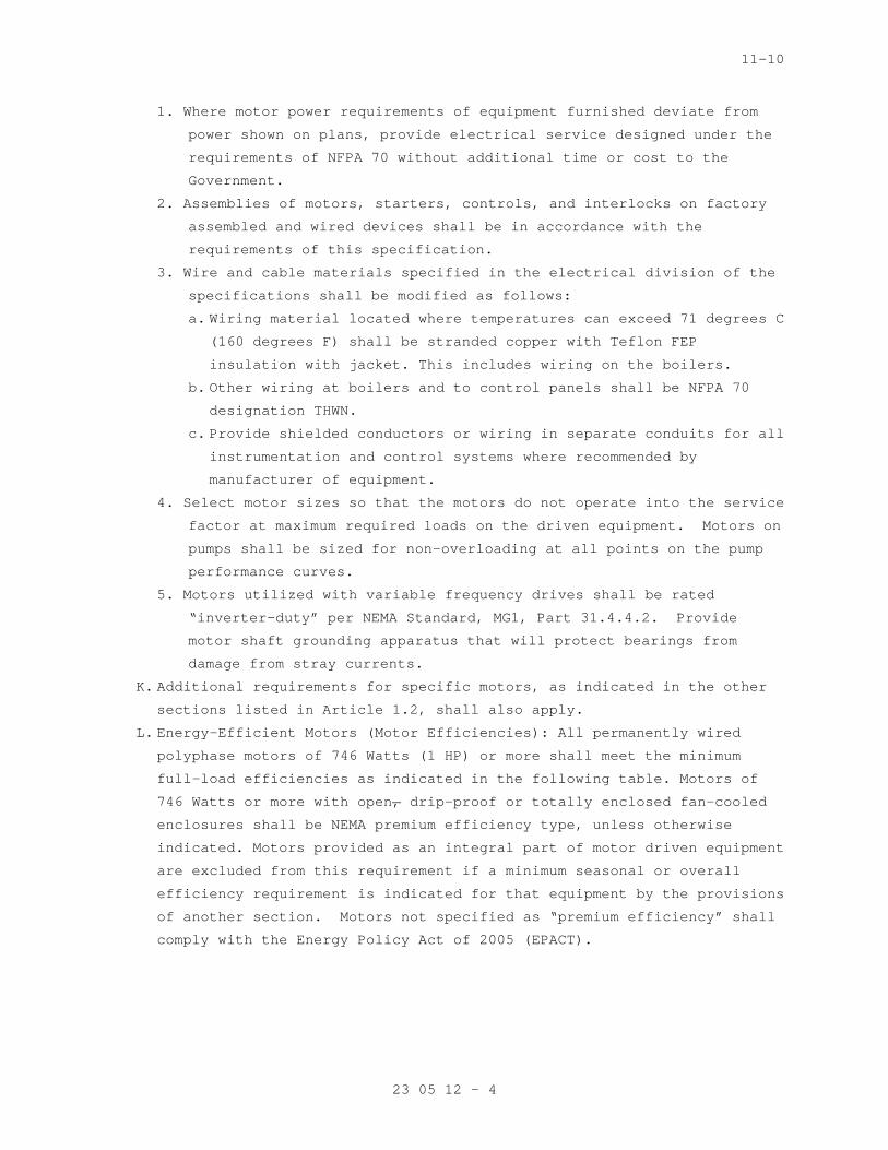
11-10
23 05 12 - 4
1. Where motor power requirements of equipment furnish ed deviate from
power shown on plans, provide electrical service de signed under the
requirements of NFPA 70 without additional time or cost to the
Government.
2. Assemblies of motors, starters, controls, and inter locks on factory
assembled and wired devices shall be in accordance with the
requirements of this specification.
3. Wire and cable materials specified in the electrica l division of the
specifications shall be modified as follows:
a. Wiring material located where temperatures can exce ed 71 degrees C
(160 degrees F) shall be stranded copper with Teflo n FEP
insulation with jacket. This includes wiring on the boilers.
b. Other wiring at boilers and to control panels shall be NFPA 70
designation THWN.
c. Provide shielded conductors or wiring in separate c onduits for all
instrumentation and control systems where recommend ed by
manufacturer of equipment.
4. Select motor sizes so that the motors do not operat e into the service
factor at maximum required loads on the driven equi pment. Motors on
pumps shall be sized for non-overloading at all poi nts on the pump
performance curves.
5. Motors utilized with variable frequency drives shal l be rated
“inverter-duty” per NEMA Standard, MG1, Part 31.4.4 .2. Provide
motor shaft grounding apparatus that will protect b earings from
damage from stray currents.
K. Additional requirements for specific motors, as ind icated in the other
sections listed in Article 1.2, shall also apply.
L. Energy-Efficient Motors (Motor Efficiencies): All p ermanently wired
polyphase motors of 746 Watts (1 HP) or more shall meet the minimum
full-load efficiencies as indicated in the followin g table. Motors of
746 Watts or more with open, drip-proof or totally enclosed fan-cooled
enclosures shall be NEMA premium efficiency type, u nless otherwise
indicated. Motors provided as an integral part of m otor driven equipment
are excluded from this requirement if a minimum sea sonal or overall
efficiency requirement is indicated for that equipm ent by the provisions
of another section. Motors not specified as “premi um efficiency” shall
comply with the Energy Policy Act of 2005 (EPACT).

11-10
23 05 12 - 5
Minimum Premium Efficiencies
Open Drip-Proof
Minimum Premium Efficiencies
Totally Enclosed Fan-Cooled
Rating
kW (HP)
1200
RPM
1800
RPM
3600
RPM
Rating
kW (HP)
1200
RPM
1800
RPM
3600
RPM
0.746 (1) 82.5% 85.5% 77.0% 0.746 (1) 82.5% 85.5% 77.0%
1.12 (1.5) 86.5% 86.5% 84.0% 1.12 (1.5) 87.5% 86. 5% 84.0%
1.49 (2) 87.5% 86.5% 85.5% 1.49 (2) 88.5% 86.5% 85. 5%
2.24 (3) 88.5% 89.5% 85.5% 2.24 (3) 89.5% 89.5% 86. 5%
3.73 (5) 89.5% 89.5% 86.5% 3.73 (5) 89.5% 89.5% 88. 5%
5.60 (7.5) 90.2% 91.0% 88.5% 5.60 (7.5) 91.0% 91.7% 89.5%
7.46 (10) 91.7% 91.7% 89.5% 7.46 (10) 91.0% 91.7% 9 0.2%
11.2 (15) 91.7% 93.0% 90.2% 11.2 (15) 91.7% 92.4% 9 1.0%
14.9 (20) 92.4% 93.0% 91.0% 14.9 (20) 91.7% 93.0% 9 1.0%
18.7 (25) 93.0% 93.6% 91.7% 18.7 (25) 93.0% 93.6% 9 1.7%
22.4 (30) 93.6% 94.1% 91.7% 22.4 (30) 93.0% 93.6% 91.7%
29.8 (40) 94.1% 94.1% 92.4% 29.8 (40) 94.1% 94.1% 9 2.4%
37.3 (50) 94.1% 94.5% 93.0% 37.3 (50) 94.1% 94.5% 9 3.0%
44.8 (60) 94.5% 95.0% 93.6% 44.8 (60) 94.5% 95.0% 9 3.6%
56.9 (75) 94.5% 95.0% 93.6% 56.9 (75) 94.5% 95.4% 9 3.6%
74.6 (100) 95.0% 95.4% 93.6% 74.6 (100) 95.0% 95.4% 94.1%
93.3 (125) 95.0% 95.4% 94.1% 93.3 (125) 95.0% 95.4% 95.0%
112 (150) 95.4% 95.8% 94.1% 112 (150) 95.8% 95.8% 9 5.0%
149.2 (200) 95.4% 95.8% 95.0% 149.2 (200) 95.8% 96. 2% 95.4%
M. Minimum Power Factor at Full Load and Rated Volt age: 90 percent at 1200
RPM, 1800 RPM and 3600 RPM.
PART 3 - EXECUTION
3.1 INSTALLATION:
A. Install motors in accordance with manufacturer’s re commendations, the
NEC, NEMA, as shown on the drawings and/or as requi red by other sections
of these specifications.
3.2 FIELD TESTS
A. Perform an electric insulation resistance Test usin g a megohmmeter on
all motors after installation, before start-up. All shall test free from
grounds.
B. Perform Load test in accordance with ANSI/IEEE 112, Test Method B, to
determine freedom from electrical or mechanical def ects and compliance
with performance data.
C. Insulation Resistance: Not less than one-half meg-o hm between stator
conductors and frame, to be determined at the time of final inspection.

11-10
23 05 12 - 6
3.3 STARTUP AND TESTING
A. The Commissioning Agent will observe startup and co ntractor testing of
selected equipment. Coordinate the startup and con tractor testing
schedules with VA Project Engineer and Commissionin g Agent. Provide a
minimum of 7 days prior notice.
3.4 COMMISSIONING
A. Provide commissioning documentation in accordance w ith the requirements
of Section 23 08 00 – COMMISSIONING OF HVAC SYSTEMS for all inspection,
start up, and contractor testing required above and required by the
System Readiness Checklist provided by the Commissi oning Agent.
B. Components provided under this section of the speci fication will be
tested as part of a larger system. Refer to Sectio n 23 08 00 –
COMMISSIONING OF HVAC SYSTEMS and related sections for contractor
responsibilities for system commissioning.
3.5 DEMONSTRATION AND TRAINING
A. Provide services of manufacturer’s technical repres entative for two
hours to instruct VA personnel in operation and mai ntenance of units.
B. Submit training plans and instructor qualifications in accordance with
the requirements of Section 23 08 00 – COMMISSIONIN G OF HVAC SYSTEMS.
- - - E N D O F S E C T I O N - - -
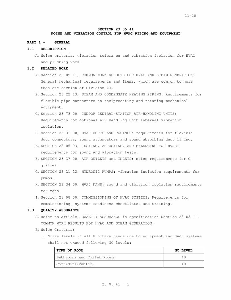
11-10
23 05 41 - 1
SECTION 23 05 41 NOISE AND VIBRATION CONTROL FOR HVAC PIPING AND EQUIPMENT
PART 1 - GENERAL
1.1 DESCRIPTION
A. Noise criteria, vibration tolerance and vibration i solation for HVAC
and plumbing work.
1.2 RELATED WORK
A. Section 23 05 11, COMMON WORK RESULTS FOR HVAC AND STEAM GENERATION:
General mechanical requirements and items, which ar e common to more
than one section of Division 23.
B. Section 23 22 13, STEAM AND CONDENSATE HEATING PIPI NG: Requirements for
flexible pipe connectors to reciprocating and rotat ing mechanical
equipment.
C. Section 23 73 00, INDOOR CENTRAL-STATION AIR-HANDLI NG UNITS:
Requirements for optional Air Handling Unit interna l vibration
isolation.
D. Section 23 31 00, HVAC DUCTS AND CASINGS: requireme nts for flexible
duct connectors, sound attenuators and sound absorb ing duct lining.
E. SECTION 23 05 93, TESTING, ADJUSTING, AND BALANCING FOR HVAC:
requirements for sound and vibration tests.
F. SECTION 23 37 00, AIR OUTLETS and INLETS: noise req uirements for G-
grilles.
G. SECTION 23 21 23, HYDRONIC PUMPS: vibration isolati on requirements for
pumps.
H. SECTION 23 34 00, HVAC FANS: sound and vibration is olation requirements
for fans.
I. Section 23 08 00, COMMISSIONING OF HVAC SYSTEMS: Re quirements for
commissioning, systems readiness checklists, and tr aining.
1.3 QUALITY ASSURANCE
A. Refer to article, QUALITY ASSURANCE in specificatio n Section 23 05 11,
COMMON WORK RESULTS FOR HVAC AND STEAM GENERATION.
B. Noise Criteria:
1. Noise levels in all 8 octave bands due to equipment and duct systems
shall not exceed following NC levels:
TYPE OF ROOM NC LEVEL
Bathrooms and Toilet Rooms 40
Corridors(Public) 40

11-10
23 05 41 - 2
Kitchens 50
Locker Rooms 45
Offices, Large Open 40
Offices, Small Private 35
Patient Rooms 35
2. For equipment which has no sound power ratings sche duled on the
plans, the contractor shall select equipment such t hat the fore-
going noise criteria, local ordinance noise levels, and OSHA re-
quirements are not exceeded. Selection procedure sh all be in
accordance with ASHRAE Fundamentals Handbook, Chapt er 7, Sound and
Vibration.
3. An allowance, not to exceed 5db, may be added to th e measured value
to compensate for the variation of the room attenua ting effect
between room test condition prior to occupancy and design condition
after occupancy which may include the addition of s ound absorbing
material, such as, furniture. This allowance may no t be taken after
occupancy. The room attenuating effect is defined a s the difference
between sound power level emitted to room and sound pressure level
in room.
4. In absence of specified measurement requirements, m easure equipment
noise levels three feet from equipment and at an el evation of maxi-
mum noise generation.
C. Vibration Criteria:
1. Allowable Vibration Tolerances for Rotating, Non-re ciprocating
Equipment: Not to exceed a self-excited vibration m aximum velocity
of 5 mm per second (0.20 inch per second) RMS, filt er in, when
measured with a vibration meter on bearing caps of machine in
vertical, horizontal and axial directions or measur ed at equipment
mounting feet if bearings are concealed. Measuremen ts for internally
isolated fans and motors may be made at the mountin g feet.
1.4 SUBMITTALS
A. Submit in accordance with specification Section 01 33 23, SHOP
DRAWINGS, PRODUCT DATA, AND SAMPLES.
B. Manufacturer's Literature and Data:
1. Vibration isolators:
a. Floor mountings
b. Hangers

11-10
23 05 41 - 3
c. Thrust restraints
2. Bases.
C. Isolator manufacturer shall furnish with submittal load calculations
for selection of isolators, including supplemental bases, based on
lowest operating speed of equipment supported.
1.5 APPLICABLE PUBLICATIONS
A. The publications listed below form a part of this s pecification to the
extent referenced. The publications are referenced in the text by the
basic designation only.
B. American Society of Heating, Refrigerating and Air- Conditioning
Engineers, Inc. (ASHRAE):
2009 ...................Fundamentals Handbook, Chapter 7 , Sound and
Vibration
C. American Society for Testing and Materials (ASTM):
A123/A123M-09...........Standard Specification for Zinc (Hot-Dip
Galvanized) Coatings on Iron and Steel Products
A307-07b................Standard Specification for Carbon Steel Bolts
and Studs, 60,000 PSI Tensile Strength
D2240-05(2010)..........Standard Test Method for Ru bber Property -
Durometer Hardness
D. Manufacturers Standardization (MSS):
SP-58-2009..............Pipe Hangers and Supports-M aterials, Design and
Manufacture
E. Occupational Safety and Health Administration (OSHA ):
29 CFR 1910.95..........Occupational Noise Exposure
F. American Society of Civil Engineers (ASCE):
ASCE 7-10 ..............Minimum Design Loads for Buildings an d Other
Structures.
G. American National Standards Institute / Sheet Metal and Air
Conditioning Contractor’s National Association (ANS I/SMACNA):
001-2008................Seismic Restraint Manual: G uidelines for
Mechanical Systems, 3rd Edition.
H. International Code Council (ICC):
2009 IBC................International Building Code.
I. Department of Veterans Affairs (VA):
H-18-8 2010.............Seismic Design Requirements .
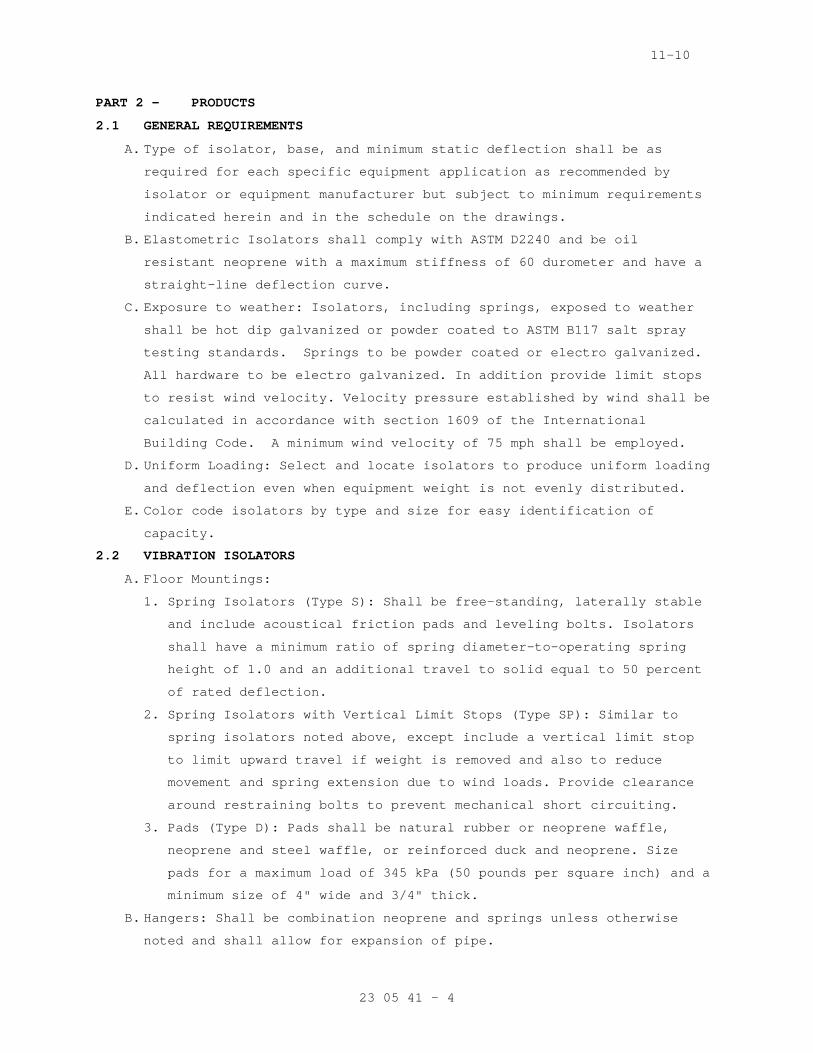
11-10
23 05 41 - 4
PART 2 - PRODUCTS
2.1 GENERAL REQUIREMENTS
A. Type of isolator, base, and minimum static deflecti on shall be as
required for each specific equipment application as recommended by
isolator or equipment manufacturer but subject to m inimum requirements
indicated herein and in the schedule on the drawing s.
B. Elastometric Isolators shall comply with ASTM D2240 and be oil
resistant neoprene with a maximum stiffness of 60 d urometer and have a
straight-line deflection curve.
C. Exposure to weather: Isolators, including springs, exposed to weather
shall be hot dip galvanized or powder coated to AST M B117 salt spray
testing standards. Springs to be powder coated or electro galvanized.
All hardware to be electro galvanized. In addition provide limit stops
to resist wind velocity. Velocity pressure establis hed by wind shall be
calculated in accordance with section 1609 of the I nternational
Building Code. A minimum wind velocity of 75 mph s hall be employed.
D. Uniform Loading: Select and locate isolators to pro duce uniform loading
and deflection even when equipment weight is not ev enly distributed.
E. Color code isolators by type and size for easy iden tification of
capacity.
2.2 VIBRATION ISOLATORS
A. Floor Mountings:
1. Spring Isolators (Type S): Shall be free-standing, laterally stable
and include acoustical friction pads and leveling b olts. Isolators
shall have a minimum ratio of spring diameter-to-op erating spring
height of 1.0 and an additional travel to solid equ al to 50 percent
of rated deflection.
2. Spring Isolators with Vertical Limit Stops (Type SP ): Similar to
spring isolators noted above, except include a vert ical limit stop
to limit upward travel if weight is removed and als o to reduce
movement and spring extension due to wind loads. Pr ovide clearance
around restraining bolts to prevent mechanical shor t circuiting.
3. Pads (Type D): Pads shall be natural rubber or neop rene waffle,
neoprene and steel waffle, or reinforced duck and n eoprene. Size
pads for a maximum load of 345 kPa (50 pounds per s quare inch) and a
minimum size of 4" wide and 3/4" thick.
B. Hangers: Shall be combination neoprene and springs unless otherwise
noted and shall allow for expansion of pipe.
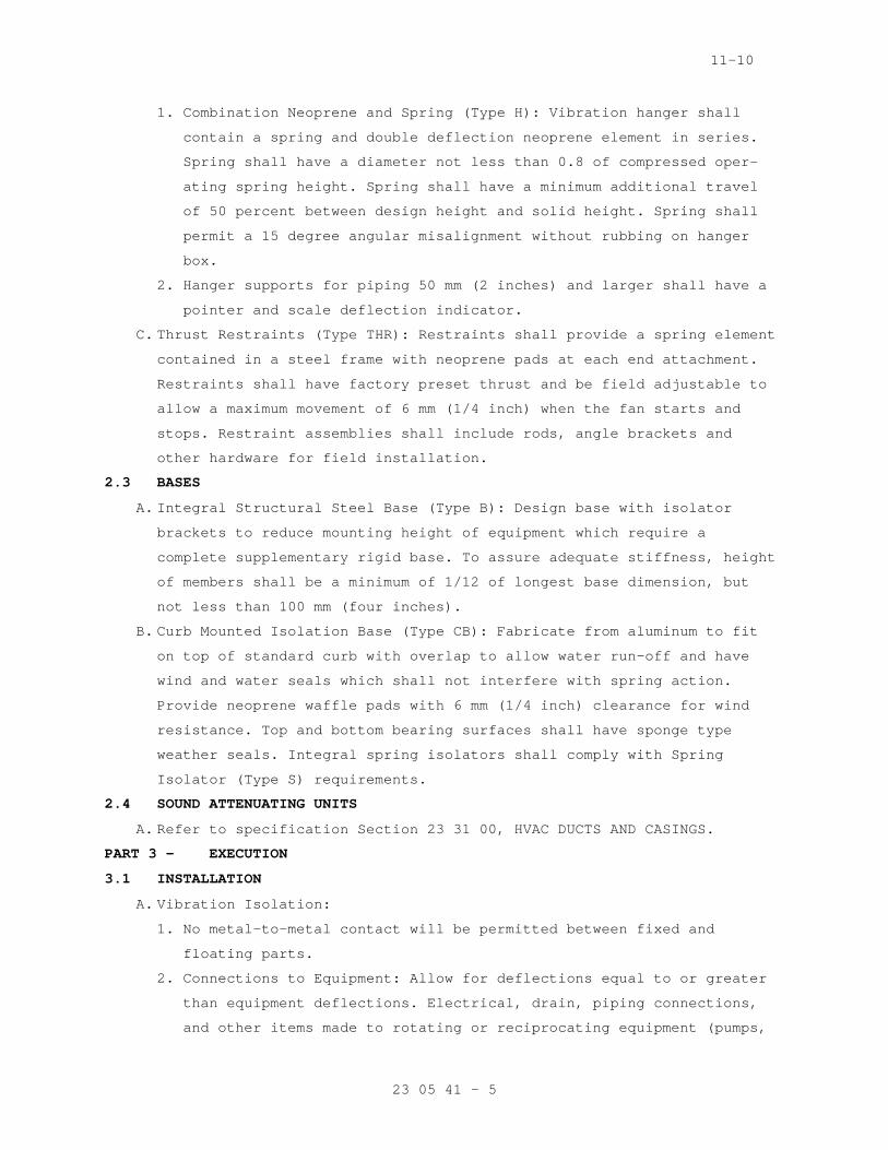
11-10
23 05 41 - 5
1. Combination Neoprene and Spring (Type H): Vibration hanger shall
contain a spring and double deflection neoprene ele ment in series.
Spring shall have a diameter not less than 0.8 of c ompressed oper-
ating spring height. Spring shall have a minimum ad ditional travel
of 50 percent between design height and solid heigh t. Spring shall
permit a 15 degree angular misalignment without rub bing on hanger
box.
2. Hanger supports for piping 50 mm (2 inches) and lar ger shall have a
pointer and scale deflection indicator.
C. Thrust Restraints (Type THR): Restraints shall prov ide a spring element
contained in a steel frame with neoprene pads at ea ch end attachment.
Restraints shall have factory preset thrust and be field adjustable to
allow a maximum movement of 6 mm (1/4 inch) when th e fan starts and
stops. Restraint assemblies shall include rods, ang le brackets and
other hardware for field installation.
2.3 BASES
A. Integral Structural Steel Base (Type B): Design bas e with isolator
brackets to reduce mounting height of equipment whi ch require a
complete supplementary rigid base. To assure adequa te stiffness, height
of members shall be a minimum of 1/12 of longest ba se dimension, but
not less than 100 mm (four inches).
B. Curb Mounted Isolation Base (Type CB): Fabricate fr om aluminum to fit
on top of standard curb with overlap to allow water run-off and have
wind and water seals which shall not interfere with spring action.
Provide neoprene waffle pads with 6 mm (1/4 inch) c learance for wind
resistance. Top and bottom bearing surfaces shall h ave sponge type
weather seals. Integral spring isolators shall comp ly with Spring
Isolator (Type S) requirements.
2.4 SOUND ATTENUATING UNITS
A. Refer to specification Section 23 31 00, HVAC DUCTS AND CASINGS.
PART 3 - EXECUTION
3.1 INSTALLATION
A. Vibration Isolation:
1. No metal-to-metal contact will be permitted between fixed and
floating parts.
2. Connections to Equipment: Allow for deflections equ al to or greater
than equipment deflections. Electrical, drain, pipi ng connections,
and other items made to rotating or reciprocating e quipment (pumps,
11-10
23 05 41 - 6
compressors, etc.) which rests on vibration isolato rs, shall be
isolated from building structure for first three ha ngers or supports
with a deflection equal to that used on the corresp onding equipment.
3. Common Foundation: Mount each electric motor on sam e foundation as
driven machine. Hold driving motor and driven machi ne in positive
rigid alignment with provision for adjusting motor alignment and
belt tension. Bases shall be level throughout lengt h and width.
Provide shims to facilitate pipe connections, level ing, and bolting.
4. Provide heat shields where elastomers are subject t o temperatures
over 38 degrees C (l00 degrees F).
5. Extend bases for pipe elbow supports at discharge a nd suction
connections at pumps. Pipe elbow supports shall not short circuit
pump vibration to structure.
6. Non-rotating equipment such as heat exchangers and convertors shall
be mounted on isolation units having the same stati c deflection as
the isolation hangers or support of the pipe connec ted to the
equipment.
B. Inspection and Adjustments: Check for vibration and noise transmission
through connections, piping, ductwork, foundations, and walls. Adjust,
repair, or replace isolators as required to reduce vibration and noise
transmissions to specified levels.
3.2 ADJUSTING
A. Adjust vibration isolators after piping systems are filled and
equipment is at operating weight.
B. Adjust limit stops on restrained spring isolators t o mount equipment at
normal operating height. After equipment installati on is complete,
adjust limit stops so they are out of contact durin g normal operation.
C. Attach thrust limits at centerline of thrust and ad just to a maximum of
1/4inch (6-mm) movement during start and stop.
D. Adjust active height of spring isolators.
3.3 COMMISSIONING
A. Provide commissioning documentation in accordance w ith the requirements
of section 23 08 00 – COMMISSIONING OF HVAC SYSTEMS for all inspection,
start up, and contractor testing required above and required by the
System Readiness Checklist provided by the Commissi oning Agent.
B. Components provided under this section of the speci fication will be
tested as part of a larger system. Refer to sectio n 23 08 00 –

11-10
23 05 41 - 7
COMMISSIONING OF HVAC SYSTEMS and related sections for contractor
responsibilities for system commissioning.
- - - E N D - - -

11-10
T-1
SELECTION GUIDE FOR VIBRATION ISOLATORS
EQUIPMENT ON GRADE 20FT FLOOR SPAN 30FT FLOOR SPAN 40FT FLOOR SPAN 50FT FLOOR SPAN
BASE TYPE
ISOL TYPE
MIN DEFL
BASE TYPE
ISOL TYPE
MIN DEFL
BASE TYPE
ISOL TYPE
MIN DEFL
BASE TYPE
ISOL TYPE
MIN DEFL
BASE TYPE
ISOL TYPE
MIN DEFL
OUTDOOR AIR CONDENSERS
UP THROUGH 1-1/2 HP
--- D 0.8 ---- D 0.8 --- D 1.5 --- D 1.5 --- D ---
2 HP AND OVER:
500 - 750 RPM --- D 0.8 --- S 0.8 --- S 1.5 --- S 1 .5 --- S 2.5
750 RPM & OVER --- D 0.8 --- S 0.8 --- S 1.5 --- S 1.5 --- S 2.5
CENTRIFUGAL FANS
UP TO 50 HP:
UP TO 200 RPM B S 0.3 B S 2.5 B S 2.5 B S 3.5 B S 3 .5
201 - 300 RPM B S 0.3 B S 2.0 B S 2.5 B S 2.5 B S 3 .5
301 - 500 RPM B S 0.3 B S 2.0 B S 2.0 B S 2.5 B S 3 .5
501 RPM & OVER B S 0.3 B S 2.0 B S 2.0 B S 2.0 B S 2.5
AIR HANDLING UNIT PACKAGES AND SUSPENDED INLINE FANS
SUSPENDED INLINE FANS:
UP THRU 5 HP --- --- --- --- H 1.0 --- H 1.0 --- H 1.0 --- H 1.0
7-1/2 HP & OVER:
UP TO 500 RPM --- --- --- --- H, THR
1.5 --- H, THR
2.5 --- H, THR
2.5 --- H, THR
2.5

11-10
T-2
EQUIPMENT ON GRADE 20FT FLOOR SPAN 30FT FLOOR SPAN 40FT FLOOR SPAN 50FT FLOOR SPAN
BASE TYPE
ISOL TYPE
MIN DEFL
BASE TYPE
ISOL TYPE
MIN DEFL
BASE TYPE
ISOL TYPE
MIN DEFL
BASE TYPE
ISOL TYPE
MIN DEFL
BASE TYPE
ISOL TYPE
MIN DEFL
501 RPM & OVER --- --- --- --- H, THR
0.8 --- H, THR
0.8 --- H,THR
0.8 --- H,THR
2.0
FLOOR MOUNTED:
UP THRU 5 HP B D --- B D 1.0 B D 1.0 B D 1.0 B D 1. 0
7-1/2 HP & OVER:
UP TO 500 RPM B D --- B D 1.5 B D 2.5 B D 2.5 B D 2 .5
501 RPM & OVER B D --- B D 0.8 B D 0.8 B D 1.5 B D 2.0
CONDENSING UNITS
ALL --- SP 0.25 --- SP 0.75 --- SP 1.5 CB SP 1.5 -- - --- NA
IN-LINE CENTRIFUGAL AND VANE AXIAL FANS, FLOOR MOUNTED:
UP THRU 50 HP:
UP TO 300 RPM --- D --- R S 2.5 R S 2.5 R S 2.5 R S 3.5
301 - 500 RPM --- D --- R S 2.0 R S 2.0 R S 2.5 R S 2.5
501 - & OVER --- D --- --- S 1.0 --- S 1.0 R S 2.0 R S 2.5

05-11
23 05 93 - 1
SECTION 23 05 93 TESTING, ADJUSTING, AND BALANCING FOR HVAC
PART 1 - GENERAL
1.1 DESCRIPTION
A. Testing, adjusting, and balancing (TAB) of heating, ventilating and air
conditioning (HVAC) systems. TAB includes the follo wing:
1. Planning systematic TAB procedures.
2. Design Review Report.
3. Systems Inspection report.
4. Duct Air Leakage test report.
5. Systems Readiness Report.
6. Balancing air and water distribution systems; adjus tment of total
system to provide design performance; and testing p erformance of
equipment and automatic controls.
7. Vibration measurements.
8. Recording and reporting results.
B. Definitions:
1. Basic TAB used in this Section: Chapter 37, "Testin g, Adjusting and
Balancing" of 2007 ASHRAE Handbook, "HVAC Applicati ons".
2. TAB: Testing, Adjusting and Balancing; the process of checking and
adjusting HVAC systems to meet design objectives.
3. AABC: Associated Air Balance Council.
4. NEBB: National Environmental Balancing Bureau.
Hydronic Systems: Includes chilled water, heating h ot water, and
glycol-water systems.
a. Air Systems: Includes all outside air, supply air, return air,
exhaust air and relief air systems.
b. Flow rate tolerance: The allowable percentage varia tion, minus to
plus, of actual flow rate from values (design) in t he contract
documents.
1.2 RELATED WORK
A. Section 23 05 11, COMMON WORK RESULTS FOR HVAC: Gen eral Mechanical
Requirements.
B. Section 23 05 41, NOISE AND VIBRATION CONTROL FOR H VAC PIPING AND
EQUIPMENT: Noise and Vibration Requirements.
C. Section 23 07 11, HVAC INSULATION: Piping and Equip ment Insulation.
D. Section 23 64 00, PACKAGED WATER CHILLERS: Testing Refrigeration
Equipment.

05-11
23 05 93 - 2
E. Section 23 36 00, AIR TERMINAL UNITS: Terminal Unit s Performance.
F. Section 23 31 00, HVAC DUCTS AND CASINGS: Duct Leak age.
G. Section 23 09 23, DIRECT-DIGITAL CONTROL SYSTEM FOR HVAC: Controls and
Instrumentation Settings.
H. Section 23 82 16, AIR COILS
I. Section 23 82 00, CONVECTION HEATING AND COOLING UN ITS
J. Section 23 73 00, INDOOR CENTRAL-STATION AIR-HANDLI NG UNITS
K. Section 23 34 00, HVAC FANS
L. Section 23 21 23, HYDRONIC PUMPS
M. Section 23 37 00, AIR OUTLETS AND INLETS
N. Section 23 81 23, COMPUTER-ROOM AIR-CONDITIONERS AN D VARIABLE
REFRIGERANT VOLUME SYSTEMS.
O. Section 23 21 13, HYDRONIC PIPING
P. Section 23 08 00, COMMISSIONING OF HVAC SYSTEMS. Re quirements for
commissioning, systems readiness checklists, and tr aining
Q. Section 23 05 12 GENERAL MOTOR REQUIREMENTS FOR HVA C AND STEAM
GENERATION EQUIPMENT
1.3 QUALITY ASSURANCE
A. Refer to Articles, Quality Assurance and Submittals , in Section
23 05 11, COMMON WORK RESULTS FOR HVAC and Section 23 08 00,
COMMISSIONING OF HVAC SYSTEMS.
B. Qualifications:
1. TAB Agency: The TAB agency shall be a subcontractor of the General
Contractor and shall report to and be paid by the G eneral
Contractor.
2. The TAB agency shall be either a certified member o f AABC or
certified by the NEBB to perform TAB service for HV AC, water
balancing and vibrations and sound testing of equip ment. The
certification shall be maintained for the entire du ration of duties
specified herein. If, for any reason, the agency lo ses subject
certification during this period, the General Contr actor shall
immediately notify the VA Project Engineer and subm it another TAB
firm for approval. Any agency that has been the sub ject of
disciplinary action by either the AABC or the NEBB within the five
years preceding Contract Award shall not be eligibl e to perform any
work related to the TAB. All work performed in this Section and in
other related Sections by the TAB agency shall be c onsidered invalid
if the TAB agency loses its certification prior to contract
05-11
23 05 93 - 3
completion, and the successor agency’s review shows unsatisfactory
work performed by the predecessor agency.
3. TAB Specialist: The TAB specialist shall be either a member of AABC
or an experienced technician of the Agency certifie d by NEBB. The
certification shall be maintained for the entire du ration of duties
specified herein. If, for any reason, the Specialis t loses subject
certification during this period, the General Contr actor shall
immediately notify the VA Project Engineer and subm it another TAB
Specialist for approval. Any individual that has be en the subject of
disciplinary action by either the AABC or the NEBB within the five
years preceding Contract Award shall not be eligibl e to perform any
duties related to the HVAC systems, including TAB. All work
specified in this Section and in other related Sect ions performed by
the TAB specialist shall be considered invalid if t he TAB Specialist
loses its certification prior to Contract completio n and must be
performed by an approved successor.
4. TAB Specialist shall be identified by the General C ontractor within
60 days after the notice to proceed. The TAB specia list will be
coordinating, scheduling and reporting all TAB work and related
activities and will provide necessary information a s required by the
VA Project Engineer. The responsibilities would spe cifically
include:
a. Shall directly supervise all TAB work.
b. Shall sign the TAB reports that bear the seal of th e TAB
standard. The reports shall be accompanied by repor t forms and
schematic drawings required by the TAB standard, AA BC or NEBB.
c. Would follow all TAB work through its satisfactory completion.
d. Shall provide final markings of settings of all HVA C adjustment
devices.
e. Permanently mark location of duct test ports.
5. All TAB technicians performing actual TAB work shal l be experienced
and must have done satisfactory work on a minimum o f 3 projects
comparable in size and complexity to this project. Qualifications
must be certified by the TAB agency in writing. The lead technician
shall be certified by AABC or NEBB
C. Test Equipment Criteria: The instrumentation shall meet the
accuracy/calibration requirements established by AA BC National
Standards or by NEBB Procedural Standards for Testi ng, Adjusting and
05-11
23 05 93 - 4
Balancing of Environmental Systems and instrument m anufacturer. Provide
calibration history of the instruments to be used f or test and balance
purpose.
D. Tab Criteria:
1. One or more of the applicable AABC, NEBB or SMACNA publications,
supplemented by ASHRAE Handbook "HVAC Applications" Chapter 36, and
requirements stated herein shall be the basis for p lanning,
procedures, and reports.
2. Flow rate tolerance: Following tolerances are allow ed. For
tolerances not mentioned herein follow ASHRAE Handb ook "HVAC
Applications", Chapter 36, as a guideline. Air Filt er resistance
during tests, artificially imposed if necessary, sh all be at least
100 percent of manufacturer recommended change over pressure drop
values for pre-filters and after-filters.
a. Air handling unit and all other fans, cubic meters/ min (cubic
feet per minute): Minus 0 percent to plus l0 percen t.
b. Air terminal units (maximum values): Minus 2 percen t to plus l0
percent.
c. Minimum outside air: 0 percent to plus 10 percent.
d. Individual room air outlets and inlets, and air flo w rates not
mentioned above: Minus 5 percent to plus l0 percent except if the
air to a space is 100 CFM or less the tolerance wou ld be minus 5
to plus 5 percent.
e. Heating hot water pumps and hot water coils: Minus 5 percent to
plus 5 percent.
f. Chilled water pumps: Minus 0 percent to plus 5 perc ent.
g. Chilled water coils: Minus 0 percent to plus 5 perc ent.
h. Dedicated Air Conditioning Unit Coils: Minus 2 perc ent to plus 5
percent.
3. Systems shall be adjusted for energy efficient oper ation as
described in PART 3.
1.4 SUBMITTALS
A. Submit in accordance with Section 01 33 23, SHOP DR AWINGS, PRODUCT
DATA, and SAMPLES.
B. Submit names and qualifications of TAB agency and T AB specialists
within 60 days after the notice to proceed. Submit information on three
recently completed projects and a list of proposed test equipment.
C. Submit Following for Review and Approval:
05-11
23 05 93 - 5
1. Systems inspection report on equipment and installa tion for
conformance with design.
2. Duct Air Leakage Test Report.
3. Systems Readiness Report.
4. Final TAB reports covering flow balance and adjustm ents and
performance tests.
5. Include in final reports uncorrected installation d eficiencies noted
during TAB and applicable explanatory comments on t est results that
differ from design requirements.
D. Prior to request for Final or Partial Final inspect ion, submit
completed Test and Balance report for the area.
1.5 APPLICABLE PUBLICATIONS
A. The following publications form a part of this spec ification to the
extent indicated by the reference thereto. In text the publications are
referenced to by the acronym of the organization.
B. American Society of Heating, Refrigerating and Air Conditioning
Engineers, Inc. (ASHRAE):
2007 ...................HVAC Applications ASHRAE Handboo k, Chapter 37,
Testing, Adjusting, and Balancing and Chapter
47, Sound and Vibration Control
C. Associated Air Balance Council (AABC):
2002....................AABC National Standards for Total System
Balance
D. National Environmental Balancing Bureau (NEBB):
7th Edition 2005 ........Procedural Standards for Test ing, Adjusting,
Balancing of Environmental Systems
2nd Edition 2006 .......Procedural Standards for the Measurement of
Sound and Vibration
3rd Edition 2009 ........Procedural Standards for Whol e Building Systems
Commissioning of New Construction
E. Sheet Metal and Air Conditioning Contractors Nation al Association
(SMACNA):
3rd Edition 2002 ........HVAC SYSTEMS Testing, Adjusti ng and Balancing
PART 2 - PRODUCTS
2.1 PLUGS
A. Provide plastic plugs to seal holes drilled in duct work for test
purposes. The plastic plugs shall be caulked in pla ce to completely
seal the holes.

05-11
23 05 93 - 6
2.2 INSULATION REPAIR MATERIAL
A. See Section 23 07 11, HVAC and BOILER PLANT INSULAT ION Provide for
repair of insulation removed or damaged for TAB wor k.
PART 3 - EXECUTION
3.1 GENERAL
A. Refer to TAB Criteria in Article, Quality Assurance .
B. Obtain applicable contract documents and copies of approved submittals
for HVAC equipment and automatic control systems.
3.2 DESIGN REVIEW REPORT
A. The TAB Specialist shall review the Contract Plans and specifications
and advise the VA Project Engineer of any design de ficiencies that
would prevent the HVAC systems from effectively ope rating in accordance
with the sequence of operation specified or prevent the effective and
accurate TAB of the system. The TAB Specialist shal l provide a report
individually listing each deficiency and the corres ponding proposed
corrective action necessary for proper system opera tion.
3.3 SYSTEMS INSPECTION REPORT
A. Inspect equipment and installation for conformance with design.
B. The inspection and report is to be done after air d istribution
equipment is on site and duct installation has begu n, but well in
advance of performance testing and balancing work. The purpose of the
inspection is to identify and report deviations fro m design and ensure
that systems will be ready for TAB at the appropria te time.
C. Reports: Follow check list format developed by AABC , NEBB or SMACNA,
supplemented by narrative comments, with emphasis o n air handling units
and fans. Check for conformance with submittals. Ve rify that diffuser
and register sizes are correct.
3.4 DUCT AIR LEAKAGE TEST REPORT
A. TAB Agency shall perform the leakage test as outlin ed in "Duct leakage
Tests and Repairs" in Section 23 31 00, HVAC DUCTS and CASINGS for TAB
agency’s role and responsibilities in witnessing, r ecording and
reporting of deficiencies.
3.5 SYSTEM READINESS REPORT
A. Inspect each system to ensure that it is complete i ncluding
installation and operation of controls. Submit rep ort to PE in
standard format.
05-11
23 05 93 - 7
B. Verify that all items such as ductwork, piping, por ts, terminals,
connectors, etc., that is required for TAB are inst alled. Provide a
report to the VA Project Engineer.
3.6 TAB REPORTS
A. Submit report for systems and equipment tested and balanced to
establish satisfactory test results.
B. The TAB contractor shall provide raw data immediate ly in writing to the
VA Project Engineer if there is a problem in achiev ing intended results
before submitting a formal report.
3.7 TAB PROCEDURES
A. Tab shall be performed in accordance with the requi rement of the
Standard under which TAB agency is certified by eit her AABC or NEBB.
B. General: During TAB all related system components s hall be in full
operation. Fan and pump rotation and motor loads sh all be checked and
corrected as necessary before proceeding with TAB. Set controls and/or
block off parts of distribution systems to simulate design operation of
variable volume air or water systems for test and b alance work.
C. Coordinate TAB procedures with existing systems and any phased
construction completion requirements for the projec t. Provide TAB
reports for each phase of the project prior to part ial final
inspections of each phase of the project.
D. Allow sufficient time in construction schedule for TAB and submission
of all reports for an organized and timely correcti on of deficiencies.
E. Air Balance and Equipment Test: Include air handlin g units, fans,
terminal units, room diffusers/outlets/inlets, and computer room AC
units.
1. Artificially load air filters by partial blanking t o produce air
pressure drop of manufacturer’s recommended pressur e drop.
2. Adjust fan speeds to provide design air flow. V-bel t drives,
including fixed pitch pulley requirements, are spec ified in Section
23 05 11, COMMON WORK RESULTS FOR HVAC.
3. Test and balance systems in all specified modes of operation,
including variable volume, economizer, and fire eme rgency modes.
Verify that dampers and other controls function pro perly.
4. Balance outside air flow rates for each air handler included in this
project whether unit is being replaced or getting a controls
upgrade. Modify outside air damper or minimum outsi de air damper in
05-11
23 05 93 - 8
order to achieve scheduled outside air cfm at maxim um supply
airflow.
5. For each air handler being replaced, test and recor d the supply and
return airflows for all modes of operation prior to replacement.
Provide pitot duct traverses as required for airflo w testing. Supply
and return airflows shall be re-tested and recorded following unit
replacement. Final airflow measurements shall be ba lanced to the
originally recorded supply and return airflows or s cheduled airflows
at a minimum (whichever is higher). Provide additio nal balancing to
increase airflows even higher in coordination with owner.
6. Variable Air Volume (VAV) Systems:
a. Coordinate TAB, including system volumetric control s, with
Section 23 09 23, DIRECT-DIGITAL CONTROL SYSTEM FOR HVAC.
b. Adjust operating pressure control setpoint to maint ain the design
flow to each space with the lowest setpoint.
7. Record final measurements for air handling equipmen t performance
data sheets.
F. Water Balance and Equipment Test: Include circulati ng pumps and coils:
1. Adjust flow rates for equipment. Set coils to value s on equipment
submittals, if different from values on contract dr awings.
2. Record final measurements for hydronic equipment on performance data
sheets. Include entering and leaving water temperat ures for heating
and cooling coils, and for convertors. Include ente ring and leaving
air temperatures (DB/WB for cooling coils) for air handling units
and reheat coils. Make air and water temperature me asurements at the
same time.
3.8 VIBRATION TESTING
A. Furnish instruments and perform vibration measureme nts as specified in
Section 23 05 41, NOISE and VIBRATION CONTROL FOR H VAC PIPING and
EQUIPMENT. Provide measurements for all rotating HV AC equipment of 373
watts (1/2 horsepower) and larger, including compr essor units, pumps,
fans and motors.
B. Record initial measurements for each unit of equipm ent on test forms
and submit a report to the VA Project Engineer. Whe re vibration
readings exceed the allowable tolerance, the contra ctor shall be
directed to correct the problem. The TAB agency sha ll verify that the
corrections are done and submit a final report to t he VA Project
Engineer.

05-11
23 05 93 - 9
3.9 MARKING OF SETTINGS
A. Following approval of tab final report, the setting of all HVAC
adjustment devices including dampers shall be perma nently marked by the
TAB Specialist so that adjustment can be restored i f disturbed at any
time. Style and colors used for markings shall be c oordinated with the
VA Project Engineer.
3.10 IDENTIFICATION OF TEST PORTS
A. The TAB Specialist shall permanently and legibly id entify the location
points of duct test ports. If the ductwork has exte rior insulation, the
identification shall be made on the exterior side o f the insulation.
All penetrations through ductwork and ductwork insu lation shall be
sealed to prevent air leaks and maintain integrity of vapor barrier.
3.11 PHASING
A. Phased Projects: Testing and Balancing Work to foll ow project with
areas shall be completed per the project phasing. U pon completion of
the project all areas shall have been tested and ba lanced per the
contract documents.
B. Existing Areas: Systems that serve areas outside of the project scope
shall not be adversely affected. Measure existing p arameters where
shown to document system capacity.
3.12 COMMISSIONING
A. Provide commissioning documentation in accordance w ith the requirements
of Section 23 08 00 – COMMISSIONING OF HVAC SYSTEMS for all inspection,
start up, and contractor testing required above and required by the
System Readiness Checklist provided by the Commissi oning Agent.
B. Components provided under this section of the speci fication will be
tested as part of a larger system. Refer to Section 23 08 00 –
COMMISSIONING OF HVAC SYSTEMS and related sections for contractor
responsibilities for system commissioning.
- - E N D - - -


05-11
23 07 11 - 1
SECTION 23 07 11 HVAC INSULATION
PART 1 - GENERAL
1.1 DESCRIPTION
A. Field applied insulation for thermal efficiency and condensation
control for:
1. HVAC piping, ductwork and equipment.
B. Definitions
1. ASJ: All service jacket, white finish facing or jac ket.
2. Air conditioned space: Space having air temperature and/or humidity
controlled by mechanical equipment.
3. Cold: Equipment, ductwork or piping handling media at design
temperature of 16 degrees C (60 degrees F) or below .
4. Concealed: Ductwork and piping above ceilings and i n chases,
interstitial space, and pipe spaces.
5. Exposed: Piping, ductwork, and equipment exposed to view in finished
areas including mechanical and electrical equipment rooms or exposed
to outdoor weather. Attics and crawl spaces where a ir handling units
are located are considered to be mechanical rooms. Shafts, chases,
interstitial spaces, unfinished attics, crawl space s and pipe
basements are not considered finished areas.
6. FSK: Foil-scrim-kraft facing.
7. Hot: HVAC Ductwork handling air at design temperatu re above 16
degrees C (60 degrees F); HVAC equipment or piping handling media
above 41 degrees C (105 degrees F).
8. Density: kg/m3 - kilograms per cubic meter (Pcf - p ounds per cubic
foot).
9. Runouts: Branch pipe connections up to 25-mm (one-i nch) nominal size
to fan coil units or reheat coils for terminal unit s.
10. Thermal conductance: Heat flow rate through materia ls.
a. Flat surface: Watt per square meter (BTU per hour p er square
foot).
b. Pipe or Cylinder: Watt per square meter (BTU per ho ur per linear
foot).
11. Thermal Conductivity (k): Watt per meter, per degre e C (BTU per inch
thickness, per hour, per square foot, per degree F temperature
difference).

05-11
23 07 11 - 2
12. Vapor Retarder (Vapor Barrier): A material which r etards the
transmission (migration) of water vapor. Performan ce of the vapor
retarder is rated in terms of permeance (perms). F or the purpose of
this specification, vapor retarders shall have a ma ximum published
permeance of 0.1 perms and vapor barriers shall hav e a maximum
published permeance of 0.001 perms.
13. MPS: Medium pressure steam (110 kPa [16 psig] thru 414 kPa [59
psig].
14. MPR: Medium pressure steam condensate return.
15. LPS: Low pressure steam (103 kPa [15 psig] and belo w).
16. LPR: Low pressure steam condensate gravity return.
17. HWH: Hot water heating supply.
18. HWHR: Hot water heating return.
19. GH: Hot glycol-water heating supply.
20. GHR: Hot glycol-water heating return.
21. GC: Chilled glycol-water supply.
22. GCR: Chilled glycol-water return.
1.2 RELATED WORK
A. Section 07 84 00, FIRESTOPPING: Mineral fiber and b ond breaker behind
sealant.
B. Section 23 05 11, COMMON WORK RESULTS FOR HVAC: Gen eral mechanical
requirements and items, which are common to more th an one section of
Division 23.
C. Section 23 05 41, NOISE AND VIBRATION CONTROL FOR H VAC PIPING and
EQUIPMENT
D. Section 23 21 23, HYDRONIC PUMPS
E. Section 23 22 13, STEAM and CONDENSATE HEATING PIPI NG
F. Section 23 64 00, PACKAGED WATER CHILLERS: Compress or, evaporator and
piping.
G. Section 23 23 00, REFRIGERANT PIPING: Requirements for refrigerant
piping and fittings.
H. Section 23 21 13, HYDRONIC PIPING: Hot water, chill ed water, and glycol
piping.
I. Section 23 31 00, HVAC DUCTS AND CASINGS: Ductwork, plenum and
fittings.
J. Section 23 08 00, COMMISSIONING OF HVAC SYSTEMS. Re quirements for
commissioning, systems readiness checklists, and tr aining.

05-11
23 07 11 - 3
1.3 QUALITY ASSURANCE
A. Refer to article QUALITY ASSURANCE, in Section 23 0 5 11, COMMON WORK
RESULTS FOR HVAC.
B. Criteria:
1. Comply with NFPA 90A, particularly paragraphs 4.3.3 .1 through
4.3.3.6, 4.3.10.2.6, and 5.4.6.4, parts of which ar e quoted as
follows:
4.3.3.1 Pipe insulation and coverings, duct coverings, duct linings, vapor retarder facings, adhesives, fastene rs, tapes, and supplementary materials added to air ducts, plenums , panels, and duct silencers used in duct systems, unless otherwi se provided for in 4.3.3.1.1 or 4.3.3.1.2., shall have, in th e form in which they are used, a maximum flame spread index o f 25 without evidence of continued progressive combustion and a maximum smoke developed index of 50 when tested in accordance wit h NFPA 255, Standard Method of Test of Surface Burning Characteristics of Building Materials.
4.3.3.1.1 Where these products are to be applied with adhesiv es, they shall be tested with such adhesives applied, o r the adhesives used shall have a maximum flame spread in dex of 25 and a maximum smoke developed index of 50 when in the f inal dry state. (See 4.2.4.2.)
4.3.3.1.2 The flame spread and smoke developed index requirem ents of 4.3.3.1.1 shall not apply to air duct weatherpr oof coverings where they are located entirely outside of a buildi ng, do not penetrate a wall or roof, and do not create an expo sure hazard.
4.3.3.2 Closure systems for use with rigid and flex ible air ducts tested in accordance with UL 181, Standard for Safe ty Factory-Made Air Ducts and Air Connectors, shall have been tested, listed, and used in accordance with the conditions of their listings, in accordance with one of the following:
(1) UL 181A, Standard for Safety Closure Systems fo r Use with Rigid Air Ducts and Air Connectors
(2) UL 181B, Standard for Safety Closure Systems fo r Use with Flexible Air Ducts and Air Connectors
4.3.3.3 Air duct, panel, and plenum coverings, and pipe insulation and coverings shall not flame, glow, smo lder, or smoke when tested in accordance with a similar test for p ipe covering, ASTM C 411, Standard Test Method for Hot-Surface Pe rformance of High-Temperature Thermal Insulation, at the tempera ture to which they are exposed in service.
4.3.3.3.1 In no case shall the test temperature be below 121°C (250°F).
4.3.3.4 Air duct coverings shall not extend through walls or floors that are required to be fire stopped or requ ired to have a fire resistance rating, unless such coverings meet the requirements of 5.4.6.4.
05-11
23 07 11 - 4
4.3.3.6 Air duct coverings shall not be installed s o as to conceal or prevent the use of any service opening.
4.3.10.2.6 Materials exposed to the airflow shall b e noncombustible or limited combustible and have a ma ximum smoke developed index of 50 or comply with the following.
4.3.10.2.6.1 Electrical wires and cables and optica l fiber cables shall be listed as noncombustible or limited combus tible and have a maximum smoke developed index of 50 or shall be l isted as having a maximum peak optical density of 0.5 or les s, an average optical density of 0.15 or less, and a maximum flam e spread distance of 1.5 m (5 ft) or less when tested in acc ordance with NFPA 262, Standard Method of Test for Flame T ravel and Smoke of Wires and Cables for Use in Air-Handling S paces.
4.3.10.2.6.6 Supplementary materials for air distri bution systems shall be permitted when complying with the provisio ns of 4.3.3.
5.4.6.4 Where air ducts pass through walls, floors, or partitions that are required to have a fire resistance rating and where fire dampers are not required, the opening in the constr uction around the air duct shall be as follows:
(1) Not exceeding a 25.4 mm (1 in.) average cl earance on all sides
(2) Filled solid with an approved material cap able of preventing the passage of flame and hot gases suffi cient to ignite cotton waste when subjected to the time-temp erature fire conditions required for fire barrier penetration as specified in NFPA 251, Standard Methods of Tests of Fire Endurance of Building Construction and Materials
2. Test methods: ASTM E84, UL 723, or NFPA 255.
3. Specified k factors are at 24 degrees C (75 degrees F) mean
temperature unless stated otherwise. Where optional thermal
insulation material is used, select thickness to pr ovide thermal
conductance no greater than that for the specified material. For
pipe, use insulation manufacturer's published heat flow tables. For
domestic hot water supply and return, run out insul ation and
condensation control insulation, no thickness adjus tment need be
made.
4. All materials shall be compatible and suitable for service
temperature, and shall not contribute to corrosion or otherwise
attack surface to which applied in either the wet o r dry state.
C. Every package or standard container of insulation o r accessories
delivered to the job site for use must have a manuf acturer's stamp or
label giving the name of the manufacturer and descr iption of the
material.
05-11
23 07 11 - 5
1.4 SUBMITTALS
A. Submit in accordance with Section 01 33 23, SHOP DR AWINGS, PRODUCT
DATA, and SAMPLES.
B. Shop Drawings:
1. All information, clearly presented, shall be includ ed to determine
compliance with drawings and specifications and AST M, federal and
military specifications.
a. Insulation materials: Specify each type used and st ate surface
burning characteristics.
b. Insulation facings and jackets: Each type used. Mak e it clear
that white finish will be furnished for exposed duc twork, casings
and equipment.
c. Insulation accessory materials: Each type used.
d. Manufacturer's installation and fitting fabrication instructions
for flexible unicellular insulation.
e. Make reference to applicable specification paragrap h numbers for
coordination.
C. Samples:
1. Each type of insulation: Minimum size 100 mm (4 inc hes) square for
board/block/blanket; 150 mm (6 inches) long, full d iameter for round
types.
2. Each type of facing and jacket: Minimum size 100 mm (4 inches
square).
3. Each accessory material: Minimum 120 ML (4 ounce) l iquid container
or 120 gram (4 ounce) dry weight for adhesives/ceme nt/mastic.
1.5 STORAGE AND HANDLING OF MATERIAL
A. Store materials in clean and dry environment, pipe covering jackets
shall be clean and unmarred. Place adhesives in ori ginal containers.
Maintain ambient temperatures and conditions as req uired by printed
instructions of manufacturers of adhesives, mastics and finishing
cements.
1.6 APPLICABLE PUBLICATIONS
A. The publications listed below form a part of this s pecification to the
extent referenced. The publications are referenced in the text by basic
designation only.
B. Federal Specifications (Fed. Spec.):

05-11
23 07 11 - 6
L-P-535E (2)- 99........Plastic Sheet (Sheeting): P lastic Strip; Poly
(Vinyl Chloride) and Poly (Vinyl Chloride -
Vinyl Acetate), Rigid.
C. Military Specifications (Mil. Spec.):
MIL-A-3316C (2)-90......Adhesives, Fire-Resistant, Thermal Insulation
MIL-A-24179A (1)-87.....Adhesive, Flexible Unicellu lar-Plastic
Thermal Insulation
MIL-C-19565C (1)-88.....Coating Compounds, Thermal Insulation, Fire-and
Water-Resistant, Vapor-Barrier
MIL-C-20079H-87.........Cloth, Glass; Tape, Textile Glass; and Thread,
Glass and Wire-Reinforced Glass
D. American Society for Testing and Materials (ASTM):
A167-99(2004)...........Standard Specification for Stainless and
Heat-Resisting Chromium-Nickel Steel Plate,
Sheet, and Strip
B209-07.................Standard Specification for Aluminum and
Aluminum-Alloy Sheet and Plate
C411-05.................Standard test method for Ho t-Surface
Performance of High-Temperature Thermal
Insulation
C449-07.................Standard Specification for Mineral Fiber
Hydraulic-Setting Thermal Insulating and
Finishing Cement
C533-09.................Standard Specification for Calcium Silicate
Block and Pipe Thermal Insulation
C534-08.................Standard Specification for Preformed Flexible
Elastomeric Cellular Thermal Insulation in
Sheet and Tubular Form
C547-07.................Standard Specification for Mineral Fiber pipe
Insulation
C552-07.................Standard Specification for Cellular Glass
Thermal Insulation
C553-08.................Standard Specification for Mineral Fiber
Blanket Thermal Insulation for Commercial and
Industrial Applications
C585-09.................Standard Practice for Inner and Outer Diameters
of Rigid Thermal Insulation for Nominal Sizes
of Pipe and Tubing (NPS System) R (1998)
05-11
23 07 11 - 7
C612-10.................Standard Specification for Mineral Fiber Block
and Board Thermal Insulation
C1126-04................Standard Specification for Faced or Unfaced
Rigid Cellular Phenolic Thermal Insulation
C1136-10................Standard Specification for Flexible, Low
Permeance Vapor Retarders for Thermal
Insulation
D1668-97a (2006)........Standard Specification for Glass Fabrics (Woven
and Treated) for Roofing and Waterproofing
E84-10..................Standard Test Method for Su rface Burning
Characteristics of Building
Materials
E119-09c ................Standard Test Method for Fire Tests of Building
Construction and Materials
E136-09b................Standard Test Methods for B ehavior of Materials
in a Vertical Tube Furnace at 750 degrees C
(1380 F)
E. National Fire Protection Association (NFPA):
90A-09..................Standard for the Installati on of Air
Conditioning and Ventilating Systems
96-08...................Standards for Ventilation C ontrol and Fire
Protection of Commercial Cooking Operations
101-09..................Life Safety Code
251-06..................Standard methods of Tests o f Fire Endurance of
Building Construction Materials
255-06..................Standard Method of tests of Surface Burning
Characteristics of Building Materials
F. Underwriters Laboratories, Inc (UL):
723.....................UL Standard for Safety Test for Surface Burning
Characteristics of Building Materials with
Revision of 09/08
G. Manufacturer’s Standardization Society of the Valve and Fitting
Industry (MSS):
SP58-2009...............Pipe Hangers and Supports M aterials, Design,
and Manufacture
PART 2 - PRODUCTS
05-11
23 07 11 - 8
2.1 MINERAL FIBER
A. ASTM C1136 (Board, Block), Class 1 or 2, density 48 kg/m3 (3 pcf), k =
0.033 (0.22) at 24 degrees C (75 degrees F), extern al insulation for
temperatures up to 121 degrees C (250 degrees F) wi th foil scrim (FSK)
facing.
B. ASTM C553 (Blanket, Flexible) Type I, Grade 3, Dens ity 24 kg/m3 (1.5
pcf), k = 0.035 (0.24) at 24 degrees C (75 degrees F), for use at
temperatures up to 121 degrees C (250 degrees F) wi th foil scrim (FSK)
facing.
C. ASTM C547 (Pipe Fitting Insulation and Preformed Pi pe Insulation),
Class 1, k = 0.033 (0.23) at 24 degrees C (75 degre es F), for use at
temperatures up to 230 degrees C (450 degrees F) wi th an all service
vapor retarder jacket with polyvinyl chloride premo lded fitting
covering. PVC cover shall be provided for exposed i nsulated piping in
all areas where piping is below 8'-0" above the fin ished floor.
D. No fiberglass insulation products shall be allowed. Even though
fiberglass meets ASTM and other standards, it will not be approved.
E. The insulation shall not contain any formaldehyde o r petroleum
products.
2.2 POLYISOCYANURATE CLOSED-CELL RIGID
A. Preformed (fabricated) pipe insulation, ASTM C591, type IV,
K=0.027(0.19) at 24 degrees C (75 degrees F), flame spread not over 25,
smoke developed not over 50, for use at temperature s up to 149 degree C
(300 degree F) with factory applied PVDC or all ser vice vapor retarder
jacket with polyvinyl chloride premolded fitting co vers.
2.3 FLEXIBLE ELASTOMERIC CELLULAR THERMAL
A. ASTM C177, C518, k = 0.039 (0.27) at 24 degrees C ( 75 degrees F), flame
spread not over 25, smoke developed not over 50, fo r temperatures from
minus 4 degrees C (40 degrees F) to 93 degrees C (2 00 degrees F). No
jacket required.
2.4 INSULATION FACINGS AND JACKETS
A. Vapor retarder, higher strength with low water perm eance = 0.02 or less
perm rating, Beach puncture 50 units for insulation facing on exposed
ductwork, casings and equipment, and for pipe insul ation jackets.
Facings and jackets shall be all service type (ASJ) or PVDC Vapor
Retarder jacketing.
B. ASJ jacket shall be white kraft bonded to 0.025 mm (1 mil) thick
aluminum foil, fiberglass reinforced, with pressure sensitive adhesive

05-11
23 07 11 - 9
closure. Comply with ASTM C1136. Beach puncture 50 units, Suitable for
painting without sizing. Jackets shall have minimum 40 mm (1-1/2 inch)
lap on longitudinal joints and minimum 75 mm (3 inc h) butt strip on end
joints. Butt strip material shall be same as the ja cket. Lap and butt
strips shall be self-sealing type with factory-appl ied pressure
sensitive adhesive.
C. Vapor Retarder medium strength with low water vapor permeance of 0.02
or less perm rating), Beach puncture 25 units: Foil -Scrim-Kraft (FSK)
or PVDC vapor retarder jacketing type for concealed ductwork and
equipment.
D. Factory composite materials may be used provided th at they have been
tested and certified by the manufacturer.
E. Pipe fitting insulation covering (jackets): Fitting covering shall be
premolded to match shape of fitting and shall be po lyvinyl chloride
(PVC) conforming to Fed Spec L-P-335, composition A , Type II Grade GU,
and Type III, minimum thickness 0.7 mm (0.03 inches ). Provide color
matching vapor retarder pressure sensitive tape. Pr ovide PVC
F. Aluminum Jacket-Piping systems: ASTM B209, 3003 all oy, H-14 temper, 0.6
mm (0.023 inch) minimum thickness with locking long itudinal joints.
Jackets for elbows, tees and other fittings shall b e factory-fabricated
to match shape of fitting and of 0.6 mm (0.024) inc h minimum thickness
aluminum. Fittings shall be of same construction a s straight run
jackets but need not be of the same alloy. Factory -fabricated
stainless steel bands shall be installed on all cir cumferential joints.
Bands shall be 13 mm (0.5 inch) wide on 450 mm (18 inch) centers.
System shall be weatherproof if utilized for outsid e service.
2.5 REMOVABLE INSULATION JACKETS
A. Insulation and Jacket:
1. Non-Asbestos mineral wool.
2. Temperature maximum of 450°F, Maximum water vapor t ransmission of
0.00 perm, and maximum moisture absorption of 0.2 p ercent by volume.
3. Jacket Material: 20 gauge aluminum or galvanized st eel.
4. Construction: One piece jacket body with three-ply braided pure
Teflon or Kevlar thread and insulation sewn as part of jacket. Belt
fastened.
5. Provide jackets for all steam valves, strainers, tr aps, and
fittings.
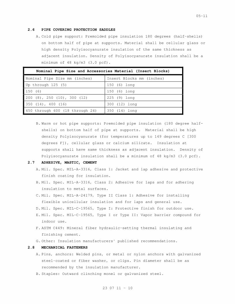
05-11
23 07 11 - 10
2.6 PIPE COVERING PROTECTION SADDLES
A. Cold pipe support: Premolded pipe insulation 180 de grees (half-shells)
on bottom half of pipe at supports. Material shall be cellular glass or
high density Polyisocyanurate insulation of the sam e thickness as
adjacent insulation. Density of Polyisocyanurate in sulation shall be a
minimum of 48 kg/m3 (3.0 pcf).
Nominal Pipe Size and Accessories Material (Insert Blocks)
Nominal Pipe Size mm (inches) Insert Blocks mm (inc hes)
Up through 125 (5) 150 (6) long
150 (6) 150 (6) long
200 (8), 250 (10), 300 (12) 225 (9) long
350 (14), 400 (16) 300 (12) long
450 through 600 (18 through 24) 350 (14) long
B. Warm or hot pipe supports: Premolded pipe insulatio n (180 degree half-
shells) on bottom half of pipe at supports. Materi al shall be high
density Polyisocyanurate (for temperatures up to 14 9 degrees C [300
degrees F]), cellular glass or calcium silicate. I nsulation at
supports shall have same thickness as adjacent insu lation. Density of
Polyisocyanurate insulation shall be a minimum of 4 8 kg/m3 (3.0 pcf).
2.7 ADHESIVE, MASTIC, CEMENT
A. Mil. Spec. MIL-A-3316, Class 1: Jacket and lap adhe sive and protective
finish coating for insulation.
B. Mil. Spec. MIL-A-3316, Class 2: Adhesive for laps a nd for adhering
insulation to metal surfaces.
C. Mil. Spec. MIL-A-24179, Type II Class 1: Adhesive f or installing
flexible unicellular insulation and for laps and ge neral use.
D. Mil. Spec. MIL-C-19565, Type I: Protective finish f or outdoor use.
E. Mil. Spec. MIL-C-19565, Type I or Type II: Vapor ba rrier compound for
indoor use.
F. ASTM C449: Mineral fiber hydraulic-setting thermal insulating and
finishing cement.
G. Other: Insulation manufacturers' published recommen dations.
2.8 MECHANICAL FASTENERS
A. Pins, anchors: Welded pins, or metal or nylon ancho rs with galvanized
steel-coated or fiber washer, or clips. Pin diamete r shall be as
recommended by the insulation manufacturer.
B. Staples: Outward clinching monel or galvanized stee l.

05-11
23 07 11 - 11
C. Wire: 1.3 mm thick (18 gage) soft annealed galvaniz ed or 1.9 mm (14
gage) copper clad steel or nickel copper alloy.
D. Bands: 13 mm (0.5 inch) nominal width, brass, galva nized steel,
aluminum or stainless steel.
2.9 REINFORCEMENT AND FINISHES
A. Tape for Flexible Elastomeric Cellular Insulation: As recommended by
the insulation manufacturer.
B. Hexagonal wire netting: 25 mm (one inch) mesh, 0.85 mm thick (22 gage)
galvanized steel.
C. Corner beads: 50 mm (2 inch) by 50 mm (2 inch), 0.5 5 mm thick (26 gage)
galvanized steel; or, 25 mm (1 inch) by 25 mm (1 in ch), 0.47 mm thick
(28 gage) aluminum angle adhered to 50 mm (2 inch) by 50 mm (2 inch)
Kraft paper.
D. PVC fitting cover: Fed. Spec L-P-535, Composition A , 11-86 Type II,
Grade GU, with Form B Mineral Fiber insert, for med ia temperature 4
degrees C (40 degrees F) to 121 degrees C (250 degr ees F). Below 4
degrees C (40 degrees F) and above 121 degrees C (2 50 degrees F).
Provide double layer insert. Provide color matching vapor barrier
pressure sensitive tape.
2.10 FIRESTOPPING MATERIAL
A. Other than pipe and duct insulation, refer to Secti on 07 84 00
FIRESTOPPING.
2.11 FLAME AND SMOKE
A. Unless shown otherwise all assembled systems shall meet flame spread 25
and smoke developed 50 rating as developed under AS TM, NFPA and UL
standards and specifications. See paragraph 1.3 "Qu ality Assurance".
PART 3 - EXECUTION
3.1 GENERAL REQUIREMENTS
A. Required pressure tests of duct and piping joints a nd connections shall
be completed and the work approved by the VA Projec t Engineer for
application of insulation. Surface shall be clean a nd dry with all
foreign materials, such as dirt, oil, loose scale a nd rust removed.
B. Except for specific exceptions, insulate entire spe cified equipment,
piping (pipe, fittings, valves, accessories), and d uct systems.
Insulate each pipe and duct individually. Do not us e scrap pieces of
insulation where a full length section will fit.
C. Insulation materials shall be installed in a first class manner with
smooth and even surfaces, with jackets and facings drawn tight and
05-11
23 07 11 - 12
smoothly cemented down at all laps. Insulation shal l be continuous
through all sleeves and openings, except at fire da mpers and duct
heaters (NFPA 90A). Vapor retarders shall be contin uous and
uninterrupted throughout systems with operating tem perature 16 degrees
C (60 degrees F) and below. Lap and seal vapor ret arder over ends and
exposed edges of insulation. Anchors, supports and other metal
projections through insulation on cold surfaces sha ll be insulated and
vapor sealed for a minimum length of 150 mm (6 inch es).
D. Install vapor stops at all insulation terminations on either side of
valves, pumps and equipment and particularly in str aight lengths of
pipe insulation.
E. Construct insulation on parts of equipment such as chilled water pumps
that must be opened periodically for maintenance or repair, so
insulation can be removed and replaced without dama ge. Install
insulation with bolted 1 mm thick (20 gage) galvani zed steel or
aluminum covers as complete units, or in sections, with all necessary
supports, and split to coincide with flange/split o f the equipment.
F. Insulation on hot piping and equipment shall be ter minated square at
items not to be insulated, access openings and name plates. Cover all
exposed raw insulation with white sealer or jacket material.
G. Protect all insulations outside of buildings with a luminum jacket using
lock joint or other approved system for a continuou s weather tight
system. Access doors and other items requiring mai ntenance or access
shall be removable and sealable.
H. HVAC work not to be insulated:
1. In hot piping: Unions, flexible connectors, control valves,
thermostatic vent valves, steam traps 20 mm (3/4 in ch) and smaller,
exposed piping through floor for convectors and rad iators. Insulate
piping to within approximately 25 mm (1 inches) of uninsulated
items.
I. Apply insulation materials subject to the manufactu rer's recommended
temperature limits. Apply adhesives, mastic and coa tings at the
manufacturer's recommended minimum coverage.
J. Elbows, flanges and other fittings shall be insulat ed with the same
material as is used on the pipe straights. The elbo w/fitting insulation
shall be field-fabricated, mitered or factory prefa bricated to the
necessary size and shape to fit on the elbow/fittin g. Use of
polyurethane spray-foam to fill a PVC elbow jacket is prohibited.

05-11
23 07 11 - 13
K. Firestop Pipe and Duct insulation:
1. Provide firestopping insulation at floor and barrie r through
penetrations. Fire stopping insulation shall be UL listed as defined
in Section 07 84 00, FIRESTOPPING.
2. Pipe and duct penetrations requiring fire stop insu lation including,
but not limited to the following:
a. Pipe risers through floors
b. Pipe or duct chase walls and floors
c. Partitions
L. Provide metal jackets over insulation as follows:
1. All piping and ducts exposed to outdoor weather.
2. A 50 mm (2 inch) overlap is required at longitudina l and
circumferential joints.
3.2 INSULATION INSTALLATION
A. Mineral Fiber Board:
1. Faced board: Apply board on pins spaced not more th an 300 mm (12
inches) on center each way, and not less than 75 mm (3 inches) from
each edge of board. In addition to pins, apply insu lation bonding
adhesive to entire underside of horizontal metal su rfaces. Butt
insulation edges tightly and seal all joints with l aps and butt
strips. After applying speed clips cut pins off flu sh and apply
vapor seal patches over clips.
2. Plain board:
a. Insulation shall be scored, beveled or mitered to p rovide tight
joints and be secured to equipment with bands space d 225 mm (9
inches) on center for irregular surfaces or with pi ns and clips
on flat surfaces. Use corner beads to protect edges of
insulation.
b. For hot equipment: Stretch 25 mm (1 inch) mesh wire , with edges
wire laced together, over insulation and finish wit h insulating
and finishing cement applied in one coat, 6 mm (1/4 inch) thick,
trowel led to a smooth finish.
c. For cold equipment: Apply meshed glass fabric in a tack coat 1.5
to 1.7 square meter per liter (60 to 70 square feet per gallon)
of vapor mastic and finish with mastic at 0.3 to 0. 4 square meter
per liter (12 to 15 square feet per gallon) over th e entire
fabric surface.
05-11
23 07 11 - 14
d. Chilled water pumps: Insulate with removable and re placeable 1 mm
thick (20 gage) aluminum or galvanized steel covers lined with
insulation. Seal closure joints/flanges of covers w ith gasket
material. Fill void space in enclosure with flexibl e mineral
fiber insulation.
3. Exposed, unlined ductwork and equipment in unfinish ed areas,
mechanical and electrical equipment rooms and attic s, and duct work
exposed to outdoor weather:
a. 50 mm (2 inch) thick insulation faced with ASJ (whi te all service
jacket): Supply air duct.
b. 50 mm (2 inch) thick insulation faced with ASJ: Re lief or
exhaust air duct.
c. Outside air intake ducts: 75 mm (three inch) thick insulation
faced with ASJ.
B. Flexible Mineral Fiber Blanket:
1. Adhere insulation to metal with 75 mm (3 inch) wide strips of
insulation bonding adhesive at 200 mm (8 inches) on center all
around duct. Additionally secure insulation to bott om of ducts
exceeding 600 mm (24 inches) in width with pins wel ded or adhered on
450 mm (18 inch) centers. Secure washers on pins. B utt insulation
edges and seal joints with laps and butt strips. St aples may be used
to assist in securing insulation. Seal all vapor re tarder
penetrations with mastic. Sagging duct insulation w ill not be
acceptable. Install firestop duct insulation where required.
2. Supply air ductwork to be insulated includes main a nd branch ducts
from AHU discharge to room supply outlets to preven t condensation.
Insulate sound attenuator units, coil casings and d amper frames. To
prevent condensation insulate trapeze type supports and angle iron
hangers for flat oval ducts that are in direct cont act with metal
duct.
3. Concealed supply air ductwork.
a. Above ceilings: 40 mm (1 ½ inch) thick insulation f aced with FSK.
4. Concealed return air duct:
a. Above ceilings at a roof level, unconditioned areas , and in
chases with external wall or containing steam pipin g; 40 mm (1-
1/2 inch) thick, insulation faced with FSK.
5. Exhaust air branch duct: 40 mm (1-1/2 inch) thick i nsulation faced
with FSK.
05-11
23 07 11 - 15
C. Molded Mineral Fiber Pipe and Tubing Covering:
1. Fit insulation to pipe or duct, aligning longitudin al joints. Seal
longitudinal joint laps and circumferential butt st rips by rubbing
hard with a nylon sealing tool to assure a positive seal. Staples
may be used to assist in securing insulation. Seal all vapor
retarder penetrations on cold piping with a generou s application of
vapor barrier mastic.
2. Nominal thickness in millimeters and inches specifi ed in the
schedule at the end of this section.
D. Polyisocyanurate Closed-Cell Rigid Insulation:
1. Polyisocyanurate closed-cell rigid insulation (PIR) may be provided
for exterior piping, equipment and ductwork for tem perature up to
149 degree C (300 degree F).
2. Install insulation, vapor barrier and jacketing per manufacturer’s
recommendations. Particular attention should be pai d to
recommendations for joint staggering, adhesive appl ication, external
hanger design, expansion/contraction joint design a nd spacing and
vapor barrier integrity.
3. Install insulation with all joints tightly butted ( except expansion)
joints in hot applications).
4. If insulation thickness exceeds 63 mm (2.5 inches), install as a
double layer system with longitudinal (lap) and but t joint
staggering as recommended by manufacturer.
5. For cold applications, vapor barrier shall be insta lled in a
continuous manner. No staples, rivets, screws or an y other
attachment device capable of penetrating the vapor barrier shall be
used to attach the vapor barrier or jacketing. No w ire ties capable
of penetrating the vapor barrier shall be used to h old the
insulation in place. Banding shall be used to attac h PVC or metal
jacketing.
6. Elbows, flanges and other fittings shall be insulat ed with the same
material as is used on the pipe straights. The elbo w/ fitting
insulation shall be field-fabricated, mitered or fa ctory
prefabricated to the necessary size and shape to fi t on the elbow/
fitting. Use of polyurethane spray-foam to fill PVC elbow jacket is
prohibited on cold applications.
05-11
23 07 11 - 16
7. For cold applications, the vapor barrier on elbows/ fittings shall be
either mastic-fabric-mastic or 2 mil thick PVDC vap or barrier
adhesive tape.
8. All PVC and metal jacketing shall be installed so a s to naturally
shed water. Joints shall point down and shall be se aled with either
adhesive or caulking (except for periodic slip join ts).
9. Minimum thickness in millimeter (inches) specified in the schedule
at the end of this section.
E. Flexible Elastomeric Cellular Thermal Insulation:
1. Apply insulation and fabricate fittings in accordan ce with the
manufacturer's installation instructions and finish with two coats
of weather resistant finish as recommended by the i nsulation
manufacturer.
2. Pipe and tubing insulation:
a. Use proper size material. Do not stretch or strain insulation.
b. To avoid undue compression of insulation, provide c ork stoppers
or wood inserts at supports as recommended by the i nsulation
manufacturer. Insulation shields are specified unde r Section
23 05 11, COMMON WORK RESULTS FOR HVAC.
c. Where possible, slip insulation over the pipe or tu bing prior to
connection, and seal the butt joints with adhesive. Where the
slip-on technique is not possible, slit the insulat ion and apply
it to the pipe sealing the seam and joints with con tact adhesive.
Optional tape sealing, as recommended by the manufa cturer, may be
employed. Make changes from mineral fiber insulatio n in a
straight run of pipe, not at a fitting. Seal joint with tape.
3. Apply sheet insulation to flat or large curved surf aces with 100
percent adhesive coverage. For fittings and large p ipe, apply
adhesive to seams only.
4. Pipe insulation: nominal thickness in millimeters ( inches as
specified in the schedule at the end of this sectio n.
5. Minimum 20 mm (0.75 inch) thick insulation for pneu matic control
lines for a minimum distance of 6 m (20 feet) from discharge side of
the refrigerated dryer.
6. Use Class S (Sheet), 20 mm (3/4 inch) thick for the following:
a. Chilled water pumps
a. Chillers, insulate any cold chiller surfaces subjec t to
condensation which has not been factory insulated.

05-11
23 07 11 - 17
7. Exposed, unlined supply and return ductwork exposed to outdoor
weather: 50 mm (2 inch) thick insulation faced with a multi-layer
vapor barrier with a water vapor permeance of 0.00 perms.
3.3 COMMISSIONING
A. Provide commissioning documentation in accordance w ith the requirements
of section 23 08 00 – COMMISSIONING OF HVAC SYSTEMS for all inspection,
start up, and contractor testing required above and required by the
System Readiness Checklist provided by the Commissi oning Agent.
B. Components provided under this section of the speci fication will be
tested as part of a larger system. Refer to sectio n 23 08 00 –
COMMISSIONING OF HVAC SYSTEMS and related sections for contractor
responsibilities for system commissioning.
3.4 PIPE INSULATION SCHEDULE
A. Provide insulation for piping systems as scheduled below:
Insulation Thickness Millimeters (Inches)
Nominal Pipe Size Millimeters (Inches)
Operating Temperature Range/Service
Insulation Material
Less than
25 (1)
25 – 32 (1 – 1¼)
38 – 75
(1½ - 3)
100 (4) and Above
122-177 degrees C (251-350 degrees F)
(MPS)
Mineral Fiber (Above ground piping only)
50 (2) 62 (2.5) 62 (2.5) 87 (3.5)
100-121 degrees C (212-250 degrees F)
(MPR, LPS)
Mineral Fiber (Above ground piping only)
38 (1.5)
50 (2.0) 75 (3.0) 75 (3.0)
38-94 degrees C (100-200 degrees F)
(LPR, HWH, HWHR, GC, GCR, GH, GHR)
Mineral Fiber (Interior Above ground piping only)
25 (1.0)
38 (1.5) 38 (1.5) 50 (2.0)
4-16 degrees C
(40-60 degrees F)
(GC, GCR)
Polyiso-cyanurate Closed-Cell Rigid (Exterior Locations only)
38 (1.5)
38 (1.5) 38 (1.5) 50 (2.0)
(40-60 degrees F)
(RL and RS for DX refrigeration,, condenser supply and return for Dedicated
Flexible Elastomeric Cellular Thermal (Above ground piping
12 (0.5)
18 (0.75)
25 (1.0) 38 (1.5)
05-11
23 07 11 - 18
A/C Units) only)
- - - E N D - - -

06-13
23 08 00 - 1
SECTION 23 08 00
COMMISSIONING OF HVAC SYSTEMS
PART 1 - GENERAL
1.1 DESCRIPTION
A. The requirements of this Section apply to all secti ons of Division 23.
This section shall be removed in its entirety under a Deduct Alternate.
Refer to Specification Section 01 00 00 General Req uirements for more
information.
B. This project will have selected building systems co mmissioned. The
complete list of equipment and systems to be commis sioned are specified
in Section 01 91 00 GENERAL COMMISSIONING REQUIREME NTS. The
commissioning process, which the Contractor is resp onsible to execute,
is defined in Section 01 91 00 GENERAL COMMISSIONIN G REQUIREMENTS. A
Commissioning Agent (CxA) hired by the general cont ractor will manage
the commissioning process. The commissioning agent may in no way be
related to or otherwise work for the architect, eng ineer, general
contractor, or sub-contractors.
1.2 RELATED WORK
A. Section 01 00 00 GENERAL REQUIREMENTS.
B. Section 01 91 00 GENERAL COMMISSIONING REQUIREMENTS .
C. Section 01 33 23 SHOP DRAWINGS, PRODUCT DATA, AND S AMPLES.
1.3 SUMMARY
A. This section includes requirements for commissionin g the HVAC systems,
subsystems and equipment. This Section supplements the general
requirements specified in Section 01 91 00 GENERAL COMMISSIONING
REQUIREMENTS.
B. The commissioning activities have been developed to support the VA
requirements to meet guidelines for Federal Leaders hip in
Environmental, Energy, and Economic Performance.
C. Refer to Section 01 91 00 GENERAL COMMISSIONING REQ UIREMENTS for more
specifics regarding processes and procedures as wel l as roles and
responsibilities for all Commissioning Team members .
1.4 DEFINITIONS
A. Refer to Section 01 91 00 GENERAL COMMISSIONING REQ UIREMENTS for
definitions.
06-13
23 08 00 - 2
1.5 COMMISSIONED SYSTEMS
A. Commissioning of a system or systems specified in D ivision 23 is part
of the construction process. Documentation and test ing of these
systems, as well as training of the VA’s Operation and Maintenance
personnel in accordance with the requirements of Se ction 01 91 00 and
of Division 23, is required in cooperation with the VA and the
Commissioning Agent.
1.6 SUBMITTALS
A. The commissioning process requires review of select ed Submittals. The
Commissioning Agent will provide a list of submitta ls that will be
reviewed by the Commissioning Agent. This list wil l be reviewed and
approved by the VA and A/E prior to forwarding to t he Contractor.
Refer to Section 01 33 23 SHOP DRAWINGS, PRODUCT DA TA, and SAMPLES for
further details.
B. The commissioning process requires submittal review simultaneously with
engineering review. Specific submittal requirements related to the
commissioning process are specified in Section 01 9 1 00 GENERAL
COMMISSIONING REQUIREMENTS.
PART 2 - PRODUCTS (NOT USED)
PART 3 - EXECUTION
3.1 CONSTRUCTION INSPECTIONS
A. Commissioning of HVAC systems will require inspecti on of individual
elements of the HVAC systems construction throughou t the construction
period. The Contractor shall coordinate with the C ommissioning Agent
in accordance with Section 01 19 00 and the Commiss ioning plan to
schedule HVAC systems inspections as required to su pport the
Commissioning Process.
3.2 PRE-FUNCTIONAL CHECKLISTS
A. The Contractor shall complete Pre-Functional Checkl ists to verify
systems, subsystems, and equipment installation is complete and systems
are ready for Systems Functional Performance Testin g. The
Commissioning Agent will prepare Pre-Functional Che cklists to be used
to document equipment installation. The Contractor shall complete the
checklists. Completed checklists shall be submitte d to the VA and A/E,
and to the Commissioning Agent for review. The Com missioning Agent may
spot check a sample of completed checklists. If th e Commissioning
Agent determines that the information provided on t he checklist is not
accurate, the Commissioning Agent will return the m arked-up checklist

06-13
23 08 00 - 3
to the Contractor for correction and resubmission. If the
Commissioning Agent determines that a significant n umber of completed
checklists for similar equipment are not accurate, the Commissioning
Agent will select a broader sample of checklists fo r review. If the
Commissioning Agent determines that a significant n umber of the broader
sample of checklists is also inaccurate, all the ch ecklists for the
type of equipment will be returned to the contracto r for correction and
resubmission. Refer to SECTION 01 91 00 GENERAL CO MMISSIONING
REQUIREMENTS for submittal requirements for Pre-Fun ctional Checklists,
Equipment Startup Reports, and other commissioning documents.
3.3 CONTRACTORS TESTS
A. Contractor tests as required by other sections of D ivision 23 shall be
scheduled and documented in accordance with Section 01 00 00 GENERAL
REQUIREMENTS. The Commissioning Agent will witness selected contractor
tests. Contractor tests shall be completed prior t o scheduling systems
Functional Performance Testing.
3.4 SYSTEMS FUNCTIONAL PERFORMANCE TESTING:
A. The Commissioning Process includes Systems Function al Performance
Testing that is intended to test systems functional performance under
steady state conditions, to test system reaction to changes in
operating conditions, and system performance under emergency
conditions. The Commissioning Agent will prepare d etailed Systems
Functional Performance Test procedures for review a nd approval by the
Project Engineer and A/E. The Contractor shall rev iew and comment on
the tests prior to approval. The Contractor shall provide the required
labor, materials, and test equipment identified in the test procedure
to perform the tests. The Commissioning Agent will witness and
document the testing. The Contractor shall sign th e test reports to
verify tests were performed. See Section 01 91 00 GENERAL
COMMISSIONING REQUIREMENTS, for additional details.
3.5 TRAINING OF VA PERSONNEL
A. Training of the VA’s operation and maintenance pers onnel is required in
cooperation with the VA Project Engineer, A/E, and Commissioning Agent.
Provide competent, factory authorized personnel to provide instruction
to operation and maintenance personnel concerning t he location,
operation, and troubleshooting of the installed sys tems. The
instruction shall be scheduled in coordination with the Project
Engineer after submission and approval of formal tr aining plans.

06-13
23 08 00 - 4
Refer to Section 01 91 00 GENERAL COMMISSIONING REQ UIREMENTS and
Division 23 Sections for additional Contractor trai ning requirements.
----- END -----

09-11
23 09 23 - 1
SECTION 23 09 23 DIRECT-DIGITAL CONTROL SYSTEM FOR HVAC
PART 1 - GENERAL
1.1 DESCRIPTION
A. Provide (a) direct-digital control system(s) as ind icated on the
project documents, point list, interoperability tab les, drawings and as
described in these specifications. Include a comple te and working
direct-digital control system. Include all enginee ring, programming,
controls and installation materials, installation l abor, commissioning
and start-up, training, final project documentation and warranty.
1. The direct-digital control system(s) shall consist of high-speed,
peer-to-peer network of DDC controllers, and a cont rol system
server..
2. The direct-digital control system(s) shall be nativ e BACnet. All
new workstations, controllers, devices and componen ts shall be listed
by BACnet Testing Laboratories. All new workstatio ns, controller,
devices and components shall be accessible using a web browser
interface and shall communicate exclusively using t he ASHRAE Standard
135 BACnet communications protocol without the use of gateways,
unless otherwise allowed by this section of the tec hnical
specifications, specifically shown on the design dr awings and
specifically requested otherwise by the VA.
3. The work administered by this Section of the techni cal
specifications shall include all labor, materials, special tools,
equipment, enclosures, power supplies, software, so ftware licenses,
Project specific software configurations and databa se entries,
interfaces, wiring, installation, labeling, enginee ring, calibration,
documentation, submittals, testing, verification, t raining services,
permits and licenses, transportation, shipping, han dling,
administration, supervision, management, insurance, Warranty,
specified services and items required for complete and fully
functional Controls Systems.
4. The control systems shall be designed such that eac h mechanical
system shall operate under stand-alone mode. The co ntractor
administered by this Section of the technical speci fications shall
provide controllers for each mechanical system. In the event of a
network communication failure, or the loss of any o ther controller,
the control system shall continue to operate indepe ndently. Failure
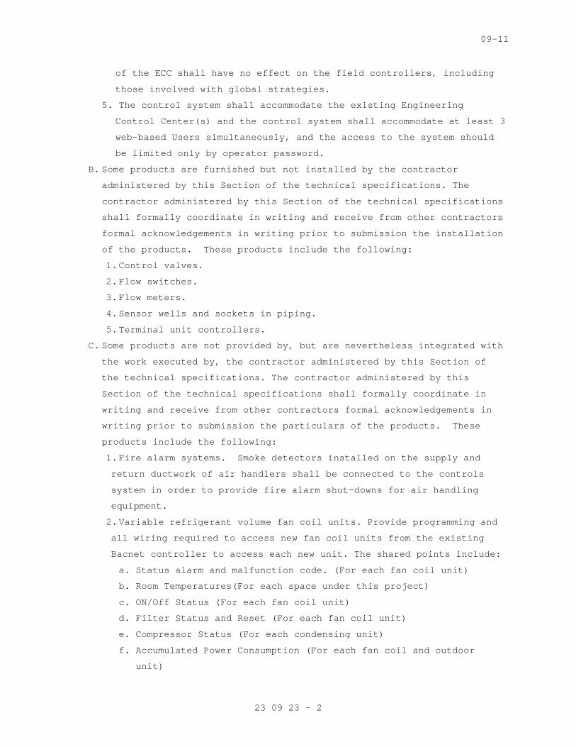
09-11
23 09 23 - 2
of the ECC shall have no effect on the field contro llers, including
those involved with global strategies.
5. The control system shall accommodate the existing E ngineering
Control Center(s) and the control system shall acco mmodate at least 3
web-based Users simultaneously, and the access to t he system should
be limited only by operator password.
B. Some products are furnished but not installed by th e contractor
administered by this Section of the technical speci fications. The
contractor administered by this Section of the tech nical specifications
shall formally coordinate in writing and receive fr om other contractors
formal acknowledgements in writing prior to submiss ion the installation
of the products. These products include the follow ing:
1. Control valves.
2. Flow switches.
3. Flow meters.
4. Sensor wells and sockets in piping.
5. Terminal unit controllers.
C. Some products are not provided by, but are neverthe less integrated with
the work executed by, the contractor administered b y this Section of
the technical specifications. The contractor admini stered by this
Section of the technical specifications shall forma lly coordinate in
writing and receive from other contractors formal a cknowledgements in
writing prior to submission the particulars of the products. These
products include the following:
1. Fire alarm systems. Smoke detectors installed on t he supply and
return ductwork of air handlers shall be connected to the controls
system in order to provide fire alarm shut-downs fo r air handling
equipment.
2. Variable refrigerant volume fan coil units. Provide programming and
all wiring required to access new fan coil units fr om the existing
Bacnet controller to access each new unit. The shar ed points include:
a. Status alarm and malfunction code. (For each fan co il unit)
b. Room Temperatures(For each space under this project )
c. ON/Off Status (For each fan coil unit)
d. Filter Status and Reset (For each fan coil unit)
e. Compressor Status (For each condensing unit)
f. Accumulated Power Consumption (For each fan coil an d outdoor
unit)

09-11
23 09 23 - 3
g. Indoor Fan Status (For each fan coil unit)
h. Start/Stop Operation (For each fan coil and outdoor unit)
i. Room Temperature Setting (For each space under this project)
j. Remote Controller Enable/Disable (For each fan coil unit)
3. Airflow control valves and room pressure sensors/co ntrollers. Refer
to 23 36 00 for more information. The BAS operator' s workstation shall
receive at a minimum the following information from the isolation room
pressure controllers (provide all wiring connection s as necessary):
a. Room differential pressure and alarm.
b. Room differential pressure alarm low limit for nega tive pressure.
c. Room Temperature.
d. Alarm delay.
e. Supply, return, and exhaust airflow.
f. Condition banner indication (Room pressure mode).
g. Room occupancy status.
h. Door condition and door alarm condition.
4. Unitary HVAC equipment (Computer Room A/C Units) co ntrols. These
include:
a. Discharge air temperature.
b. Return air temperature.
c. Minimum and maximum return air temperature in last 24 hours.
d. Humidity level and setpoint.
e. Unit On/Off status.
f. Room temperature and setpoint.
g. Water temperature.
h. Status alarm.
5. Variable frequency drives. These controls, if not n ative BACnet,
will require a BACnet Gateway.
a. The following points shall be made available as a m inimum to be
communicated via the communications interface into the Building
Automation System:
1) Fault diagnostics
2) Meter points:
3) Motor power in HP
4) Motor power in kW
5) Motor kW-hr
6) Motor current
7) Motor voltage
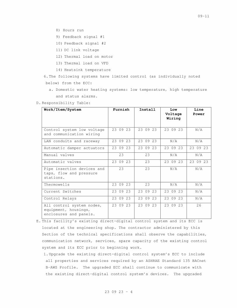
09-11
23 09 23 - 4
8) Hours run
9) Feedback signal #1
10) Feedback signal #2
11) DC link voltage
12) Thermal load on motor
13) Thermal load on VFD
14) Heatsink temperature
6. The following systems have limited control (as indi vidually noted
below) from the ECC:
a. Domestic water heating systems: low temperature, hi gh temperature
and status alarms.
D. Responsibility Table:
Work/Item/System Furnish Install Low Voltage Wiring
Line Power
Control system low voltage and communication wiring
23 09 23 23 09 23 23 09 23 N/A
LAN conduits and raceway 23 09 23 23 09 23 N/A N/A
Automatic damper actuators 23 09 23 23 09 23 23 09 23 23 09 23
Manual valves 23 23 N/A N/A
Automatic valves 23 09 23 23 23 09 23 23 09 23
Pipe insertion devices and taps, flow and pressure stations.
23 23 N/A N/A
Thermowells 23 09 23 23 N/A N/A
Current Switches 23 09 23 23 09 23 23 09 23 N/A
Control Relays 23 09 23 23 09 23 23 09 23 N/A
All control system nodes, equipment, housings, enclosures and panels.
23 09 23 23 09 23 23 09 23 26
E. This facility’s existing direct-digital control sys tem and its ECC is
located at the engineering shop. The contractor adm inistered by this
Section of the technical specifications shall obser ve the capabilities,
communication network, services, spare capacity of the existing control
system and its ECC prior to beginning work.
1. Upgrade the existing direct-digital control system’ s ECC to include
all properties and services required by an ASHRAE S tandard 135 BACnet
B-AWS Profile. The upgraded ECC shall continue to communicate with
the existing direct-digital control system’s device s. The upgraded
09-11
23 09 23 - 5
ECC shall communicate directly with the new native- BACnet devices over
the existing control system’s communications networ k without the use
of a gateway. The contractor administered by this S ection of the
technical specifications shall provide all necessar y investigation and
site-specific programming to execute the interopera bility schedules.
The ECC shall be upgraded to the control contractor 's current
software.
F. This campus has standardized on an existing standar d ASHRAE Standard
135, BACnet/IP Control System supported by a presel ected controls
service company (G & R Controls – Siemens, Trane, o r Direct Digital
Control) – see plan for specific controls required in certain areas
(i.e. Trane controls only in Building 13). This ent ity is referred to
as the “Control System Integrator” in this Section of the technical
specifications. The Control system integrator is r esponsible for ECC
system graphics and expansion. It also prescribes control system-
specific commissioning/verification procedures to t he contractor
administered by this Section of the technical speci fication. It lastly
provides limited assistance to the contractor admin istered by this
Section of the technical specification in its
commissioning/verification work. The Control System Integrator shall be
removed under Deduct Alternate. Refer to Specificat ion Section 01 00 00
General Requirements for more information. If the d educt alternate is
accepted, each controls contractor shall be respons ible for its own
ECC, system graphics and expansion. All of the item s in the “Control
System Integrator” column (of the responsibility ta ble on the next
page) would turn into the responsibility of the con trols contractor
(Section 23 09 23 Contractor) if the alternate is a ccepted.
1. The General Contractor of this project shall direct ly hire the
Control System Integrator in a contract separate fr om the contract
procuring the controls contractor administered by t his Section of the
technical specifications.
2. The contractor administered by this Section of the technical
specifications shall coordinate all work with the C ontrol System
Integrator. The contractor administered by this Se ction of the
technical specifications shall integrate the ASHRAE Standard 135,
BACnet/IP control network(s) with the Control Syste m Integrator’s area
control through an Ethernet connection provided by the Control System
Integrator.
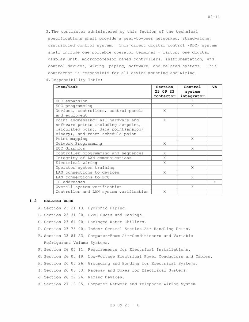
09-11
23 09 23 - 6
3. The contractor administered by this Section of the technical
specifications shall provide a peer-to-peer network ed, stand-alone,
distributed control system. This direct digital co ntrol (DDC) system
shall include one portable operator terminal - lapt op, one digital
display unit, microprocessor-based controllers, ins trumentation, end
control devices, wiring, piping, software, and rela ted systems. This
contractor is responsible for all device mounting a nd wiring.
4. Responsibility Table:
Item/Task Section 23 09 23 contactor
Control system
integrator
VA
ECC expansion X ECC programming X Devices, controllers, control panels and equipment
X
Point addressing: all hardware and software points including setpoint, calculated point, data point(analog/ binary), and reset schedule point
X
Point mapping X Network Programming X ECC Graphics X Controller programming and sequences X Integrity of LAN communications X Electrical wiring X Operator system training X LAN connections to devices X LAN connections to ECC X IP addresses X Overall system verification X Controller and LAN system verification X
1.2 RELATED WORK
A. Section 23 21 13, Hydronic Piping.
B. Section 23 31 00, HVAC Ducts and Casings.
C. Section 23 64 00, Packaged Water Chillers.
D. Section 23 73 00, Indoor Central-Station Air-Handli ng Units.
E. Section 23 81 23, Computer-Room Air-Conditioners an d Variable
Refrigerant Volume Systems.
F. Section 26 05 11, Requirements for Electrical Insta llations.
G. Section 26 05 19, Low-Voltage Electrical Power Cond uctors and Cables.
H. Section 26 05 26, Grounding and Bonding for Electri cal Systems.
I. Section 26 05 33, Raceway and Boxes for Electrical Systems.
J. Section 26 27 26, Wiring Devices.
K. Section 27 10 05, Computer Network and Telephone Wi ring System
09-11
23 09 23 - 7
1.3 DEFINITION
A. Algorithm: A logical procedure for solving a recurr ent mathematical
problem; A prescribed set of well-defined rules or processes for the
solution of a problem in a finite number of steps.
B. Analog: A continuously varying signal value (e.g., temperature,
current, velocity etc.
C. BACnet: A Data Communication Protocol for Building Automation and
Control Networks, ANSI/ASHRAE Standard 135. This c ommunications
protocol allows diverse building automation devices to communicate data
over and services over a network.
D. BACnet/IP: Annex J of Standard 135. It defines and allows for using a
reserved UDP socket to transmit BACnet messages ove r IP networks. A
BACnet/IP network is a collection of one or more IP sub-networks that
share the same BACnet network number.
E. BACnet Internetwork: Two or more BACnet networks co nnected with
routers. The two networks may sue different LAN te chnologies.
F. BACnet Network: One or more BACnet segments that ha ve the same network
address and are interconnected by bridges at the ph ysical and data link
layers.
G. BACnet Segment: One or more physical segments of BA Cnet devices on a
BACnet network, connected at the physical layer by repeaters.
H. BACnet Broadcast Management Device (BBMD): A commun ications device
which broadcasts BACnet messages to all BACnet/IP d evices and other
BBMDs connected to the same BACnet/IP network.
I. BACnet Interoperability Building Blocks (BIBBs): BA Cnet
Interoperability Building Blocks (BIBBs) are collec tions of one or more
BACnet services. These are prescribed in terms of a n "A" and a "B"
device. Both of these devices are nodes on a BACnet internetwork.
J. BACnet Testing Laboratories (BTL). The organization responsible for
testing products for compliance with the BACnet sta ndard, operated
under the direction of BACnet International.
K. Baud: It is a signal change in a communication link . One signal change
can represent one or more bits of information depen ding on type of
transmission scheme. Simple peripheral communicatio n is normally one
bit per Baud. (e.g., Baud rate = 78,000 Baud/sec is 78,000 bits/sec, if
one signal change = 1 bit).
L. Binary: A two-state system where a high signal leve l represents an "ON"
condition and an "OFF" condition is represented by a low signal level.
09-11
23 09 23 - 8
M. BMP or bmp: Suffix, computerized image file, used a fter the period in a
DOS-based computer file to show that the file is an image stored as a
series of pixels.
N. Bus Topology: A network topology that physically in terconnects
workstations and network devices in parallel on a n etwork segment.
O. Control Unit (CU): Generic term for any controlling unit, stand-alone,
microprocessor based, digital controller residing o n secondary LAN or
Primary LAN, used for local controls or global cont rols
P. Deadband: A temperature range over which no heating or cooling is
supplied, i.e., 22-25 degrees C (72-78 degrees F), as opposed to a
single point change over or overlap).
Q. Device: a control system component that contains a BACnet Device Object
and uses BACnet to communicate with other devices.
R. Device Object: Every BACnet device requires one Dev ice Object, whose
properties represent the network visible properties of that device.
Every Device Object requires a unique Object Identi fier number on the
BACnet internetwork. This number is often referred to as the device
instance.
S. Device Profile: A specific group of services descri bing BACnet
capabilities of a device, as defined in ASHRAE Stan dard 135-2008, Annex
L. Standard device profiles include BACnet Operator Workstations (B-
OWS), BACnet Building Controllers (B-BC), BACnet Ad vanced Application
Controllers (B-AAC), BACnet Application Specific Co ntrollers (B-ASC),
BACnet Smart Actuator (B-SA), and BACnet Smart Sens or (B-SS). Each
device used in new construction is required to have a PICS statement
listing which service and BIBBs are supported by th e device.
T. Diagnostic Program: A software test program, which is used to detect
and report system or peripheral malfunctions and fa ilures. Generally,
this system is performed at the initial startup of the system.
U. Direct Digital Control (DDC): Microprocessor based control including
Analog/Digital conversion and program logic. A cont rol loop or
subsystem in which digital and analog information i s received and
processed by a microprocessor, and digital control signals are
generated based on control algorithms and transmitt ed to field devices
in order to achieve a set of predefined conditions.
V. Distributed Control System: A system in which the p rocessing of system
data is decentralized and control decisions can and are made at the
subsystem level. System operational programs and in formation are
09-11
23 09 23 - 9
provided to the remote subsystems and status is rep orted back to the
Engineering Control Center. Upon the loss of commun ication with the
Engineering Control center, the subsystems shall be capable of
operating in a stand-alone mode using the last best available data.
W. Download: The electronic transfer of programs and d ata files from a
central computer or operation workstation with seco ndary memory devices
to remote computers in a network (distributed) syst em.
X. DXF: An AutoCAD 2-D graphics file format. Many CAD systems import and
export the DXF format for graphics interchange.
Y. Electrical Control: A control circuit that operates on line or low
voltage and uses a mechanical means, such as a temp erature sensitive
bimetal or bellows, to perform control functions, s uch as actuating a
switch or positioning a potentiometer.
Z. Electronic Control: A control circuit that operates on low voltage and
uses a solid-state components to amplify input sign als and perform
control functions, such as operating a relay or pro viding an output
signal to position an actuator.
AA. Engineering Control Center (ECC): The centralized c ontrol point
for the intelligent control network. The ECC compri ses of personal
computer and connected devices to form a single wor kstation.
BB. Ethernet: A trademark for a system for exchanging m essages
between computers on a local area network using coa xial, fiber optic,
or twisted-pair cables.
CC. Firmware: Firmware is software programmed into read only memory
(ROM) chips. Software may not be changed without ph ysically altering
the chip.
DD. Gateway: Communication hardware connecting two or m ore different
protocols. It translates one protocol into equivale nt concepts for the
other protocol. In BACnet applications, a gateway h as BACnet on one
side and non-BACnet (usually proprietary) protocols on the other side.
EE. GIF: Abbreviation of Graphic interchange format.
FF. Graphic Program (GP): Program used to produce image s of air
handler systems, fans, chillers, pumps, and buildin g spaces. These
images can be animated and/or color-coded to indica te operation of the
equipment.
GG. Graphic Sequence of Operation: It is a graphical re presentation
of the sequence of operation, showing all inputs an d output logical
blocks.
09-11
23 09 23 - 10
HH. I/O Unit: The section of a digital control system t hrough which
information is received and transmitted. I/O refers to analog input
(AI, digital input (DI), analog output (AO) and dig ital output (DO).
Analog signals are continuous and represent tempera ture, pressure, flow
rate etc, whereas digital signals convert electroni c signals to digital
pulses (values), represent motor status, filter sta tus, on-off
equipment etc.
II. I/P: a method for conveying and routing packets of information
over LAN paths. User Datagram Protocol (UDP) conve ys information to
“sockets” without confirmation of receipt. Transmis sion Control
Protocol (TCP) establishes "sessions", which have e nd-to-end
confirmation and guaranteed sequence of delivery.
JJ. JPEG: A standardized image compression mechanism st ands for Joint
Photographic Experts Group, the original name of th e committee that
wrote the standard.
KK. Local Area Network (LAN): A communication bus that interconnects
operator workstation and digital controllers for pe er-to-peer
communications, sharing resources and exchanging in formation.
LL. Network Repeater: A device that receives data packe t from one
network and rebroadcasts to another network. No rou ting information is
added to the protocol.
MM. Native BACnet Device: A device that uses BACnet as its primary
method of communication with other BACnet devices w ithout intermediary
gateways. A system that uses native BACnet devices at all levels is a
native BACnet system.
NN. Network Number: A site-specific number assigned to each network
segment to identify for routing. This network numbe r must be unique
throughout the BACnet internetwork.
OO. Object: The concept of organizing BACnet informatio n into
standard components with various associated propert ies. Examples
include analog input objects and binary output obje cts.
PP. Object Identifier: An object property used to ident ify the
object, including object type and instance. Object Identifiers must be
unique within a device.
QQ. Object Properties: Attributes of an object. Example s include
present value and high limit properties of an analo g input object.
Properties are defined in ASHRAE 135; some are opti onal and some are
09-11
23 09 23 - 11
required. Objects are controlled by reading from an d writing to object
properties.
RR. Operating system (OS): Software, which controls the execution of
computer application programs.
SS. PCX: File type for an image file. When photographs are scanned
onto a personal computer they can be saved as PCX f iles and viewed or
changed by a special application program as Photo S hop.
TT. Peripheral: Different components that make the cont rol system
function as one unit. Peripherals include monitor, printer, and I/O
unit.
UU. Peer-to-Peer: A networking architecture that treats all network
stations as equal partners- any device can initiate and respond to
communication with other devices.
VV. PICS: Protocol Implementation Conformance Statement , describing
the BACnet capabilities of a device. All BACnet de vices have published
PICS.
WW. PID: Proportional, integral, and derivative control , used to
control modulating equipment to maintain a setpoint .
XX. Repeater: A network component that connects two or more physical
segments at the physical layer.
YY. Router: a component that joins together two or more networks
using different LAN technologies. Examples include joining a BACnet
Ethernet LAN to a BACnet MS/TP LAN.
ZZ. Sensors: devices measuring state points or flows, w hich are then
transmitted back to the DDC system.
AAA. Thermostats : devices measuring temperatures, which are used in
control of standalone or unitary systems and equipm ent not attached to
the DDC system.
1.4 QUALITY ASSURANCE
A. Criteria:
1. Single Source Responsibility of subcontractor: The Contractor shall
obtain hardware and software supplied under this Se ction and
delegate the responsibility to a single source cont rols installation
subcontractor. The controls subcontractor shall be responsible for
the complete design, installation, and commissionin g of the system.
The controls subcontractor shall be in the business of design,
installation and service of such building automatio n control systems
similar in size and complexity.

09-11
23 09 23 - 12
2. Equipment and Materials: Equipment and materials sh all be cataloged
products of manufacturers regularly engaged in prod uction and
installation of HVAC control systems. Products shal l be
manufacturer’s latest standard design and have been tested and
proven in actual use.
3. The controls subcontractor shall provide a list of no less than five
similar projects which have building control system s as specified in
this Section. These projects must be on-line and fu nctional such
that the Department of Veterans Affairs (VA) repres entative would
observe the control systems in full operation.
4. The controls subcontractor shall have in-place faci lity within 50
miles with technical staff, spare parts inventory f or the next five
(5) years, and necessary test and diagnostic equipm ent to support
the control systems.
5. The controls subcontractor shall have minimum of th ree years
experience in design and installation of building a utomation systems
similar in performance to those specified in this S ection. Provide
evidence of experience by submitting resumes of the project manager,
the local branch manager, project engineer, the app lication
engineering staff, and the electronic technicians w ho would be
involved with the supervision, the engineering, and the installation
of the control systems. Training and experience of these personnel
shall not be less than three years. Failure to disc lose this
information will be a ground for disqualification o f the supplier.
6. Provide a competent and experienced Project Manager employed by the
Controls Contractor. The Project Manager shall be s upported as
necessary by other Contractor employees in order to provide
professional engineering, technical and management service for the
work. The Project Manager shall attend scheduled Pr oject Meetings as
required and shall be empowered to make technical, scheduling and
related decisions on behalf of the Controls Contrac tor.
B. Codes and Standards:
1. All work shall conform to the applicable Codes and Standards.
2. Electronic equipment shall conform to the requireme nts of FCC
Regulation, Part 15, Governing Radio Frequency Elec tromagnetic
Interference, and be so labeled.
1.5 PERFORMANCE
A. The system shall conform to the following:

09-11
23 09 23 - 13
1. Graphic Display: The system shall display up to fou r (4) graphics on
a single screen with a minimum of twenty (20) dynam ic points per
graphic. All current data shall be displayed within ten (10) seconds
of the request.
2. Graphic Refresh: The system shall update all dynami c points with
current data within eight (8) seconds. Data refresh shall be
automatic, without operator intervention.
3. Object Command: The maximum time between the comman d of a binary
object by the operator and the reaction by the devi ce shall be
two(2) seconds. Analog objects shall start to adjus t within two (2)
seconds.
4. Object Scan: All changes of state and change of ana log values shall
be transmitted over the high-speed network such tha t any data used
or displayed at a controller or work-station will b e current, within
the prior six (6) seconds.
5. Alarm Response Time: The maximum time from when an object goes into
alarm to when it is annunciated at the workstation shall not exceed
(10) seconds.
6. Program Execution Frequency: Custom and standard ap plications shall
be capable of running as often as once every (5) se conds. The
Contractor shall be responsible for selecting execu tion times
consistent with the mechanical process under contro l.
7. Multiple Alarm Annunciations: All workstations on t he network shall
receive alarms within five (5) seconds of each othe r.
8. Performance: Programmable Controllers shall be able to execute DDC
PID control loops at a selectable frequency from at least once every
one (1) second. The controller shall scan and updat e the process
value and output generated by this calculation at t his same
frequency.
9. Reporting Accuracy: Listed below are minimum accept able reporting
end-to-end accuracies for all values reported by th e specified
system:
Measured Variable Reported Accuracy
Space temperature ±0.5 °C (±1 °F)
Ducted air temperature ±0.5 °C [±1 °F]
Outdoor air temperature ±1.0 °C [±2 °F]
Dew Point ±1.5 °C [±3 °F]
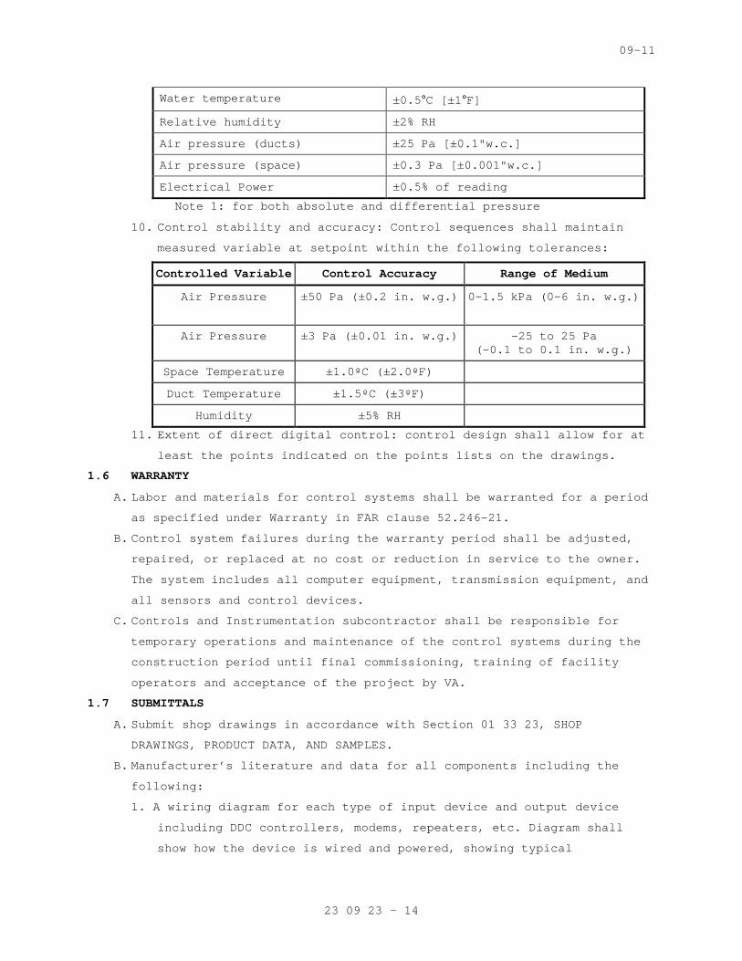
09-11
23 09 23 - 14
Water temperature ±0.5 °C [±1 °F]
Relative humidity ±2% RH
Air pressure (ducts) ±25 Pa [±0.1"w.c.]
Air pressure (space) ±0.3 Pa [±0.001"w.c.]
Electrical Power ±0.5% of reading
Note 1: for both absolute and differential pressure
10. Control stability and accuracy: Control sequences s hall maintain
measured variable at setpoint within the following tolerances:
Controlled Variable Control Accuracy Range of Medium
Air Pressure ±50 Pa (±0.2 in. w.g.)
0–1.5 kPa (0–6 in. w.g.)
Air Pressure ±3 Pa (±0.01 in. w.g.) -25 to 25 Pa (-0.1 to 0.1 in. w.g.)
Space Temperature ±1.0ºC (±2.0ºF)
Duct Temperature ±1.5ºC (±3ºF)
Humidity ±5% RH
11. Extent of direct digital control: control design sh all allow for at
least the points indicated on the points lists on t he drawings.
1.6 WARRANTY
A. Labor and materials for control systems shall be wa rranted for a period
as specified under Warranty in FAR clause 52.246-21 .
B. Control system failures during the warranty period shall be adjusted,
repaired, or replaced at no cost or reduction in se rvice to the owner.
The system includes all computer equipment, transmi ssion equipment, and
all sensors and control devices.
C. Controls and Instrumentation subcontractor shall be responsible for
temporary operations and maintenance of the control systems during the
construction period until final commissioning, trai ning of facility
operators and acceptance of the project by VA.
1.7 SUBMITTALS
A. Submit shop drawings in accordance with Section 01 33 23, SHOP
DRAWINGS, PRODUCT DATA, AND SAMPLES.
B. Manufacturer’s literature and data for all componen ts including the
following:
1. A wiring diagram for each type of input device and output device
including DDC controllers, modems, repeaters, etc. Diagram shall
show how the device is wired and powered, showing t ypical
09-11
23 09 23 - 15
connections at the digital controllers and each pow er supply, as
well as the device itself. Show for all field conne cted devices,
including but not limited to, control relays, motor starters,
electric or electronic actuators, and temperature p ressure, flow and
humidity sensors and transmitters.
2. A diagram of each terminal strip, including digital controller
terminal strips, terminal strip location, terminati on numbers and
the associated point names.
3. Control dampers and control valves schedule, includ ing the size and
pressure drop.
4. Catalog cut sheets of all equipment used. This incl udes, but is not
limited to software (by manufacturer and by third p arties), DDC
controllers, panels, peripherals, airflow measuring stations and
associated components, and auxiliary control device s such as
sensors, actuators, and control dampers. When manuf acturer’s cut
sheets apply to a product series rather than a spec ific product, the
data specifically applicable to the project shall b e highlighted.
Each submitted piece of literature and drawings sho uld clearly
reference the specification and/or drawings that it supposed to
represent.
5. Sequence of operations for each HVAC system and the associated
control diagrams. Equipment and control labels shal l correspond to
those shown on the drawings.
6. Color prints of proposed graphics with a list of po ints for display.
7. Furnish a BACnet Protocol Implementation Conformanc e Statement
(PICS) for each BACnet-compliant device.
8. Schematic wiring diagrams for all control, communic ation and power
wiring. Provide a schematic drawing of the central system
installation. Label all cables and ports with compu ter
manufacturers’ model numbers and functions. Show al l interface
wiring to the control system.
9. An instrumentation list for each controlled system. Each element of
the controlled system shall be listed in table form at. The table
shall show element name, type of device, manufactur er, model number,
and product data sheet number.
10. Riser diagrams of wiring between central control un it and all
control panels.

09-11
23 09 23 - 16
11. Scaled plan drawings showing routing of LAN and loc ations of control
panels, controllers, routers, gateways, ECC, and la rger controlled
devices.
12. Construction details for all installed conduit, cab ling, raceway,
cabinets, and similar. Construction details of all penetrations and
their protection.
13. Quantities of submitted items may be reviewed but a re the
responsibility of the contractor administered by th is Section of the
technical specifications.
C. Product Certificates: Compliance with Article, QUAL ITY ASSURANCE.
D. Licenses: Provide licenses for all software residin g on and used by the
Controls Systems and transfer these licenses to the Owner prior to
completion.
E. As Built Control Drawings:
1. Furnish three (3) copies of as-built drawings for e ach control
system. The documents shall be submitted for approv al prior to final
completion.
2. Furnish one (1) stick set of applicable control sys tem prints for
each mechanical system for wall mounting. The docum ents shall be
submitted for approval prior to final completion.
3. Furnish one (1) CD-ROM in CAD DWG format for the dr awings noted in
subparagraphs above. CAD version utilized must be c ompatible with
version currently used at the Fargo VA Medical Cent er.
F. Operation and Maintenance (O/M) Manuals):
1. Submit in accordance with Article, INSTRUCTIONS, in Specification
Section 01 00 00, GENERAL REQUIREMENTS. Provide har dcopy and PDF
version on CD or DVD.
2. Include the following documentation:
a. General description and specifications for all comp onents,
including logging on/off, alarm handling, producing trend
reports, overriding computer control, and changing set points and
other variables.
b. Detailed illustrations of all the control systems s pecified for
ease of maintenance and repair/replacement procedur es, and
complete calibration procedures.
c. One copy of the final version of all software provi ded including
operating systems, programming language, operator w orkstation
software, and graphics software.
09-11
23 09 23 - 17
d. Complete troubleshooting procedures and guidelines for all
systems.
e. Complete operating instructions for all systems.
f. Recommended preventive maintenance procedures for a ll system
components including a schedule of tasks for inspec tion, cleaning
and calibration. Provide a list of recommended spar e parts needed
to minimize downtime.
g. Training Manuals: Submit the course outline and tra ining material
to the Owner for approval three (3) weeks prior to the training
to VA facility personnel. These persons will be res ponsible for
maintaining and the operation of the control system s, including
programming. The Owner reserves the right to modify any or all of
the course outline and training material.
h. Licenses, guaranty, and other pertaining documents for all
equipment and systems.
G. Submit Performance Report to VA Project Engineer pr ior to final
inspection.
1.8 INSTRUCTIONS
A. Instructions to VA operations personnel: Perform in accordance with
Article, INSTRUCTIONS, in Specification Section 01 00 00, GENERAL
REQUIREMENTS, and as noted below.
1. Training shall comprise of on the job training duri ng start-up,
checkout period, and performance test period. VA fa cilities
personnel will work with the Contractor’s installat ion and test
personnel on a daily basis during start-up and chec kout period.
During the performance test period, controls subcon tractor will
provide 8 hours of instructions, given in multiple training sessions
(each no longer than four hours in length), to the VA facilities
personnel. Coordinate with the commissioning agent for all training
sessions and refer to 01 91 00 GENERAL COMMISSIONIN G REQUIREMENTS
for more information.
2. The O/M Manuals shall contain approved submittals a s outlined in
Article 1.7, SUBMITTALS. The Controls subcontractor will review the
manual contents with VA facilities personnel during second phase of
training.
3. Training shall be given by direct employees of the controls system
subcontractor.
09-11
23 09 23 - 18
1.9 PROJECT CONDITIONS (ENVIRONMENTAL CONDITIONS OF OPERATION)
A. The ECC and peripheral devices and system support e quipment shall be
designed to operate in ambient condition of 20 to 3 5°C (65 to 90 °F) at a
relative humidity of 20 to 80% non-condensing.
B. All electronic equipment shall operate properly wit h power fluctuations
of plus 10 percent to minus 15 percent of nominal s upply voltage.
C. Sensors and controlling devices shall be designed t o operate in the
environment, which they are sensing or controlling.
1.10 APPLICABLE PUBLICATIONS
A. The publications listed below form a part of this s pecification to the
extent referenced. The publications are referenced in the text by the
basic designation only.
B. American Society of Heating, Refrigerating, and Air -Conditioning
Engineers (ASHRAE):
Standard 135-10.........BACNET Building Automation and Control Networks
C. American Society of Mechanical Engineers (ASME):
B16.18-01...............Cast Copper Alloy Solder Jo int Pressure Fittings.
B16.22-01...............Wrought Copper and Copper A lloy Solder Joint Pressure Fittings.
D. American Society of Testing Materials (ASTM):
B32-08..................Standard Specification for Solder Metal B88-09..................Standard Specifications for Seamless Copper
Water Tube B88M-09.................Standard Specification for Seamless Copper
Water Tube (Metric) B280-08.................Standard Specification for Seamless Copper Tube
for Air-Conditioning and Refrigeration Field Service
D2737-03................Standard Specification for Polyethylene (PE) Plastic Tubing
E. Federal Communication Commission (FCC):
Rules and Regulations Title 47 Chapter 1-2001 Part 15: Radio Frequency Devices.
F. Institute of Electrical and Electronic Engineers (I EEE):
802.3-11................Information Technology-Tele communications and Information Exchange between Systems-Local and Metropolitan Area Networks- Specific Requirements-Part 3: Carrier Sense Multiple Access with Collision Detection (CSMA/CD) Access method and Physical Layer Specifications
G. National Fire Protection Association (NFPA):
70-11...................National Electric Code
09-11
23 09 23 - 19
90A-09..................Standard for Installation o f Air-Conditioning and Ventilation Systems
H. Underwriter Laboratories Inc (UL):
94-10...................Tests for Flammability of P lastic Materials for Parts and Devices and Appliances
294-10..................Access Control System Units 486A/486B-10............Wire Connectors 555S-11.................Standard for Smoke Dampers 916-10..................Energy Management Equipment 1076-10.................Proprietary Burglar Alarm U nits and Systems
PART 2 - PRODUCTS
2.1 MATERIALS
A. Use new products that the manufacturer is currently manufacturing and
that have been installed in a minimum of 25 install ations. Spare parts
shall be available for at least five years after co mpletion of this
contract.
2.2 CONTROLS SYSTEM ARCHITECTURE
A. General
1. The Controls Systems shall consist of multiple Node s and associated
equipment connected by industry standard digital an d communication
network arrangements.
2. The building controllers and principal communicatio ns network
equipment shall be standard products of recognized major
manufacturers available through normal PC and compu ter vendor
channels – not "Clones" assembled by a third-party subcontractor.
3. The networks shall, at minimum, comprise, as necess ary, the
following:
a. Active processing BACnet-compliant building control lers connected
to other BACNet-compliant controllers together with their power
supplies and associated equipment.
b. Addressable elements, sensors, transducers and end devices.
c. Third-party equipment interfaces and gateways as de scribed and
required by the Contract Documents.
d. Other components required for a complete and workin g Control
Systems as specified.
B. The specifications for the individual elements and component subsystems
shall be minimum requirements and shall be augmente d as necessary by
the Contractor to achieve both compliance with all applicable codes,
standards and to meet all requirements of the Contr act Documents.
C. Network Architecture

09-11
23 09 23 - 20
1. The controls communication network shall utilize BA Cnet
communications protocol operating over a standard E thernet LAN and
operate at a minimum speed of 100 Mb/sec.
2. The networks shall utilize only copper and optical fiber
communication media as appropriate and shall comply with applicable
codes, ordinances and regulations.
D. Third Party Interfaces:
1. The contractor administered by this Section of the technical
specifications shall include necessary hardware, eq uipment, software
and programming to allow data communications betwee n the controls
systems and building systems supplied by other trad es.
2. Other manufacturers and contractors supplying other associated
systems and equipment shall provide their necessary hardware,
software and start-up at their cost and shall coope rate fully with
the contractor administered by this Section of the technical
specifications in a timely manner and at their cost to ensure
complete functional integration.
E. Servers:
1. Provide data storage server(s) to archive historica l data including
trends, alarm and event histories and transaction l ogs. Include any
additional servers as needed for system expansion.
2. Equip these server(s) with the same software tool s et that is
located in the BACnet building controllers for syst em configuration
and custom logic definition and color graphic confi guration or
provide upgrade to all at no extra cost.
3. Access to all information on the data storage serve r(s) shall be
through the same browser functionality used to acce ss individual
nodes. When logged onto a server the operator will be able to also
interact with any other controller on the control s ystem as required
for the functional operation of the controls system s. The
contractor administered by this Section of the tech nical
specifications shall provide all necessary digital processor
programmable data storage server(s).
4. These server(s) shall be utilized for controls syst ems application
configuration, for archiving, reporting and trendin g of data, for
operator transaction archiving and reporting, for n etwork
information management, for alarm annunciation, for operator
interface tasks, for controls application managemen t and similar.
09-11
23 09 23 - 21
These server(s) shall utilize IT industry standard data base
platforms which utilize a database declarative lang uage designed for
managing data in relational database management sys tems (RDBMS) such
as SQL.
2.3 COMMUNICATION
A. Control products, communication media, connectors, repeaters, hubs, and
routers shall comprise a BACnet internetwork. Contr oller and operator
interface communication shall conform to ANSI/ASHRA E Standard 135-2008,
BACnet.
1. The Data link/physical layer protocol (for communic ation) acceptable
to the VA throughout its facilities is Ethernet (IS O 8802-3) and
BACnet/IP.
B. Each controller shall have a communication port for connection to an
operator interface.
C. Internetwork operator interface and value passing s hall be transparent
to internetwork architecture.
1. An operator interface connected to a controller sha ll allow the
operator to interface with each internetwork contro ller as if
directly connected. Controller information such as data, status,
reports, system software, and custom programs shall be viewable and
editable from each internetwork controller.
2. Inputs, outputs, and control variables used to inte grate control
strategies across multiple controllers shall be rea dable by each
controller on the internetwork. Program and test a ll cross-
controller links required to execute specified cont rol system
operation. An authorized operator shall be able to edit cross-
controller links by typing a standard object addres s.
D. System shall be expandable to at least twice the re quired input and
output objects with additional controllers, associa ted devices, and
wiring. Expansion shall not require operator interf ace hardware
additions or software revisions.
E. ECCs and Controllers with real-time clocks shall us e the BACnet Time
Synchronization service. The system shall automatic ally synchronize
system clocks daily from an operator-designated dev ice via the
internetwork. The system shall automatically adjust for daylight
savings and standard time as applicable. After powe r outages, the
system components shall automatically restart.
09-11
23 09 23 - 22
2.4 ENGINEERING CONTROL CENTER (ECC)
A. The controls contractor shall utilize the existing Operator’s
Workstation in the Mechanical Shop. If the software currently installed
on the workstation does not match the controls cont ractor’s software,
new software shall be provided. Any workstation upg rades to the
existing computer hardware or software shall be com pleted by this
contractor at this time if required.
B. The ECC shall reside on a high-speed network with c ontrollers as shown
on system drawings. The ECC and each standard brows er connected to
server shall be able to access all system informati on.
C. ECC and controllers shall communicate using BACnet protocol. ECC and
control network backbone shall communicate using IS O 8802-3 (Ethernet)
Data Link/Physical layer protocol and BACnet/IP add ressing as specified
in ASHRAE/ANSI 135-2008, BACnet Annex J. After powe r outages, the
system components shall automatically restart.
D. ECC Software:
1. Provide for automatic system database save and rest ore on the ECC’s
hard disk a copy of the current database of each Co ntroller. This
database shall be updated whenever a change is made in any system
panel. In the event of a database loss in a buildin g management
panel, the ECC shall automatically restore the data base for that
panel. This capability may be disabled by the opera tor.
2. Provide for manual database save and restore. An o perator with
proper clearance shall be able to save the database from any system
panel. The operator also shall be able to clear a p anel database and
manually initiate a download of a specified databas e to any panel in
the system.
3. Provide a method of configuring the system. This sh all allow for
future system changes or additions by users with pr oper clearance.
4. Operating System. Furnish a concurrent multi-taskin g operating
system. The operating system also shall support the use of other
common software applications. Acceptable operating systems are
Windows XP, Windows System 7, Linux, and UNIX. Veri fy operating
system preference with owner and IT department befo re making a
selection.
5. System Graphics. The operator workstation software shall be
graphically oriented. The system shall allow displa y of up to 10
graphic screens at once for comparison and monitori ng of system
09-11
23 09 23 - 23
status. Provide a method for the operator to easily move between
graphic displays and change the size and location o f graphic
displays on the screen. The system graphics shall b e able to be
modified while on-line. An operator with the proper password level
shall be able to add, delete, or change dynamic obj ects on a
graphic. Dynamic objects shall include analog and b inary values,
dynamic text, static text, and animation files. Gra phics shall have
the ability to show animation by shifting image fil es based on the
status of the object.
6. Custom Graphics. Custom graphic files shall be crea ted with the use
of a graphics generation package furnished with the system. The
graphics generation package shall be a graphically based system that
uses the mouse to create and modify graphics that a re saved in
industry standard formats such as PCX, TIFF, and GE M. The graphics
generation package also shall provide the capabilit y of capturing or
converting graphics from other programs such as Des igner or AutoCAD.
7. Graphics Library. Furnish a complete library of sta ndard HVAC
equipment graphics such as chillers, boilers, air h andlers,
terminals, fan coils, and unit ventilators. This li brary also shall
include standard symbols for other equipment includ ing fans, pumps,
coils, valves, piping, dampers, and ductwork. The l ibrary shall be
furnished in a file format compatible with the grap hics generation
package program.
8. The Controls Systems Operator Interfaces shall be u ser friendly,
readily understood and shall make maximum use of co lors, graphics,
icons, embedded images, animation, text based infor mation and data
visualization techniques to enhance and simplify th e use and
understanding of the displays by authorized users a t the ECC. The
operating system shall be Windows XP or better, and shall support
the third party software.
9. Provide graphical user software, which shall minimi ze the use of
keyboard through the use of the mouse and "point an d click" approach
to menu selection.
10. The software shall provide a multi-tasking type env ironment that
will allow the user to run several applications sim ultaneously. The
mouse or Alt-Tab keys shall be used to quickly sele ct and switch
between multiple applications. The operator shall b e able
automatically export data to and work in Microsoft Word, Excel, and

09-11
23 09 23 - 24
other Windows based software programs, while concur rently on-line
system alarms and monitoring information.
11. On-Line Help. Provide a context-sensitive, on-line help system to
assist the operator in operating and editing the sy stem. On-line
help shall be available for all applications and sh all provide the
relevant data for that particular screen. Additiona l help
information shall be available through the use of h ypertext.
12. User access shall be protected by a flexible and Ow ner re-definable
software-based password access protection. Password protection shall
be multi-level and partition able to accommodate th e varied access
requirements of the different user groups to which individual users
may be assigned. Provide the means to define unique access
privileges for each individual authorized user. Pro vide the means to
on-line manage password access control under the co ntrol of a
project specific Master Password. Provide an audit trail of all user
activity on the Controls Systems including all acti ons and changes.
13. The system shall be completely field-programmable f rom the common
operator’s keyboard thus allowing hard disk storage of all data
automatically. All programs for the CUs shall be ab le to be
downloaded from the hard disk. The software shall p rovide the
following functionality as a minimum:
a. Point database editing, storage and downloading of controller
databases.
b. Scheduling and override of building environmental c ontrol
systems.
c. Collection and analysis of historical data.
d. Alarm reporting, routing, messaging, and acknowledg ement.
e. Definition and construction of dynamic color graphi c displays.
f. Real-time graphical viewing and control of environm ent.
g. Scheduling trend reports.
h. Program editing.
i. Operating activity log and system security.
j. Transfer data to third party software.
14. Provide functionality such that using the least amo unt of steps to
initiate the desired event may perform any of the f ollowing
simultaneously:
a. Dynamic color graphics and graphic control.
b. Alarm management.
09-11
23 09 23 - 25
c. Event scheduling.
d. Dynamic trend definition and presentation.
e. Program and database editing.
f. Each operator shall be required to log on to the sy stem with a
user name and password to view, edit or delete the data. System
security shall be selectable for each operator, and the password
shall be able to restrict the operator’s access for viewing and
changing the system programs. Each operator shall a utomatically
be logged off the system if no keyboard or mouse ac tivity is
detected for a selected time.
15. Graphic Displays:
a. The workstation shall allow the operator to access various system
schematics and floor plans via a graphical penetrat ion scheme,
menu selection, or text based commands. Graphic sof tware shall
permit the importing of AutoCAD or scanned pictures in the
industry standard format (such as PCX, BMP, GIF, an d JPEG) for
use in the system.
b. System Graphics shall be project specific and schem atically
correct for each system. (ie: coils, fans, dampers located per
equipment supplied with project.) Standard system graphics that
do not match equipment or system configurations are not
acceptable. Operator shall have capability to manu ally operate
the entire system from each graphic screen at the E CC. Each
system graphic shall include a button/tab to a disp lay of the
applicable sequence of operation.
c. Dynamic temperature values, humidity values, flow r ates, and
status indication shall be shown in their locations and shall
automatically update to represent current condition s without
operator intervention and without pre-defined scree n refresh
values.
d. Color shall be used to indicate status and change i n status of
the equipment. The state colors shall be user defin able.
e. A clipart library of HVAC equipment, such as chille rs, boilers,
air handling units, fans, terminal units, pumps, co ils, standard
ductwork, piping, valves and laboratory symbols sha ll be provided
in the system. The operator shall have the ability to add custom
symbols to the clipart library.

09-11
23 09 23 - 26
f. A dynamic display of the site-specific architecture showing
status of the controllers, the ECC and network shal l be provided.
g. The windowing environment of the workstation shall allow the user
to simultaneously view several applications at a ti me to analyze
total building operation or to allow the display of graphic
associated with an alarm to be viewed without inter rupting work
in progress. The graphic system software shall also have the
capability to split screen, half portion of the scr een with
graphical representation and the other half with se quence of
operation of the same HVAC system.
16. Trend reports shall be generated on demand or pre-d efined schedule
and directed to monitor display, printers or disk. As a minimum, the
system shall allow the operator to easily obtain th e following types
of reports:
a. A general list of all selected points in the networ k.
b. List of all points in the alarm.
c. List of all points in the override status.
d. List of all disabled points.
e. List of all points currently locked out.
f. List of user accounts and password access levels.
g. List of weekly schedules.
h. List of holiday programming.
i. List of limits and dead bands.
j. Custom reports.
k. System diagnostic reports, including, list of digit al controllers
on the network.
l. List of programs.
17. Weather Reports
a. Weather Data Report: Provide a monthly report showi ng the daily
minimum, maximum, and average outdoor air temperatu re, as well as
the number of heating and cooling degree-days for e ach day.
Provide an annual (12-month) report showing the min imum, maximum,
and average outdoor air temperature for the month, as well as the
number of heating and cooling degree-days for the m onth.
18. Scheduling and Override:
a. Provide override access through menu selection from the graphical
interface and through a function key.
09-11
23 09 23 - 27
b. Provide a calendar type format for time-of-day sche duling and
overrides of building control systems. Schedules re side in the
ECC. The digital controllers shall ensure equipmen t time
scheduling when the ECC is off-line. The ECC shall not be
required to execute time scheduling. Provide the fo llowing
spreadsheet graphics as a minimum:
1) Weekly schedules.
2) Zone schedules, minimum of 100 zones.
3) Scheduling up to 365 days in advance.
4) Scheduled reports to print at workstation.
19. Collection and Analysis of Historical Data:
a. Provide trending capabilities that will allow the o perator to
monitor and store records of system activity over a n extended
period of time. Points may be trended automatically on time based
intervals or change of value, both of which shall b e user
definable. The trend interval could be five (5) min utes to 120
hours. Trend data may be stored on hard disk for fu ture
diagnostic and reporting. Additionally trend data m ay be archived
to network drives or removable disk media for off-s ite retrieval.
b. Reports may be customized to include individual poi nts or
predefined groups of at least six points. Provide a dditional
functionality to allow pre-defined groups of up to 250 trended
points to be easily accessible by other industry st andard word
processing and spreadsheet packages. The reports sh all be time
and date stamped and shall contain a report title a nd the name of
the facility.
c. System shall have the set up to generate spreadshee t reports to
track energy usage and cost based on weekly or mont hly interval,
equipment run times, equipment efficiency, and/or b uilding
environmental conditions.
d. Provide additional functionality that will allow th e operator to
view real time trend data on trend graph displays. A minimum of
20 points may be graphed regardless of whether they have been
predefined for trending. In addition, the user may pause the
graph and take snapshots of the screens to be store d on the
workstation disk for future reference and trend ana lysis. Exact
point values may be viewed and the graph may be pri nted. Operator
09-11
23 09 23 - 28
shall be able to command points directly on the tre nd plot by
double clicking on the point.
20. Alarm Management:
a. Alarm routing shall allow the operator to send alar m notification
to selected printers or operator workstation based on time of
day, alarm severity, or point type.
b. Alarm notification shall be provided via two alarm icons, to
distinguish between routine, maintenance type alarm s and critical
alarms. The critical alarms shall display on the sc reen at the
time of its occurrence, while others shall display by clicking on
their icon.
c. Alarm display shall list the alarms with highest pr iority at the
top of the display. The alarm display shall provide selector
buttons for display of the associated point graphic and message
in English language. The operator shall be able to sort out the
alarms.
d. Alarm messages shall be customized for each point t o display
detailed instructions to the operator regarding act ions to take
in the event of an alarm.
e. An operator with proper security level access may a cknowledge and
clear the alarm. All that have not been cleared sha ll be archived
at workstation disk.
2.5 BACNET PROTOCOL ANALYZER
A. For ease of troubleshooting and maintenance, provid e a BACnet protocol
analyzer. Provide its associated fittings, cables and appurtenances,
for connection to the communications network. The BACnet protocol
analyzer shall be able to, at a minimum: capture an d store to a file
all data traffic on all network levels; measure ban dwidth usage; filter
out (ignore) selected traffic.
2.6 NETWORK AND DEVICE NAMING CONVENTION
A. Network Numbers
1. BACnet network numbers shall be based on a "facilit y code, network"
concept. The "facility code" is the VAMC’s or VA ca mpus’ assigned
numeric value assigned to a specific facility or bu ilding. The
"network" typically corresponds to a "floor" or oth er logical
configuration within the building. BACnet allows 65 535 network
numbers per BACnet internet work.
09-11
23 09 23 - 29
2. The network numbers are thus formed as follows: "Ne t #" = "FFFNN"
where:
a. FFF = Facility code (see below)
b. NN = 00-99 This allows up to 100 networks per facil ity or
building
B. Device Instances
1. BACnet allows 4194305 unique device instances per B ACnet internet
work. Using Agency's unique device instances are fo rmed as follows:
"Dev #" = "FFFNNDD" where
a. FFF and N are as above and
b. DD = 00-99, this allows up to 100 devices per netwo rk.
2. Note Special cases, where the network architecture of limiting
device numbering to DD causes excessive subnet work s. The device
number can be expanded to DDD and the network numbe r N can become a
single digit. In NO case shall the network number N and the device
number D exceed 4 digits.
3. Facility code assignments:
4. 000-400 Building/facility number
5. Note that some facilities have a facility code with an alphabetic
suffix to denote wings, related structures, etc. Th e suffix will be
ignored. Network numbers for facility codes above 4 00 will be
assigned in the range 000-399.
C. Device Names
1. Name the control devices based on facility name, lo cation within a
facility, the system or systems that the device mon itors and/or
controls, or the area served. The intent of the dev ice naming is to
be easily recognized. Names can be up to 254 charac ters in length,
without embedded spaces. Provide the shortest descr iptive, but
unambiguous, name. For example, in building #123 pr efix the number
with a “B” followed by the building number, if ther e is only one
chilled water pump "CHWP-1", a valid name would be "B123.CHWP.
1.STARTSTOP". If there are two pumps designated "CH WP-1", one in a
basement mechanical room (Room 0001) and one in a p enthouse
mechanical room (Room PH01), the names could be "B1 23.R0001.CHWP.1.
STARTSTOP" or "B123.RPH01.CHWP.1.STARTSTOP". In the case of unitary
controllers, for example a VAV box controller, a na me might be
"B123.R101.VAV". These names should be used for the value of the
"Object_Name" property of the BACnet Device objects of the

09-11
23 09 23 - 30
controllers involved so that the BACnet name and th e EMCS name are
the same.
2.7 BACNET DEVICES
A. All BACnet Devices – controllers, gateways, routers , actuators and
sensors shall conform to BACnet Device Profiles and shall be BACnet
Testing Laboratories (BTL) -Listed as conforming to those Device
Profiles. Protocol Implementation Conformance Stat ements (PICSs),
describing the BACnet capabilities of the Devices s hall be published
and available of the Devices through links in the B TL website.
1. BACnet Building Controllers, historically referred to as NACs, shall
conform to the BACnet B-BC Device Profile, and shal l be BTL-Listed
as conforming to the B-BC Device Profile. The Devi ce’s PICS shall
be submitted.
2. BACnet Advanced Application Controllers shall confo rm to the BACnet
B-AAC Device Profile, and shall be BTL-Listed as co nforming to the
B-AAC Device Profile. The Device’s PICS shall be s ubmitted.
3. BACnet Application Specific Controllers shall confo rm to the BACnet
B-ASC Device Profile, and shall be BTL-Listed as co nforming to the
B-ASC Device Profile. The Device’s PICS shall be s ubmitted.
4. BACnet Smart Actuators shall conform to the BACnet B-SA Device
Profile, and shall be BTL-Listed as conforming to t he B-SA Device
Profile. The Device’s PICS shall be submitted.
5. BACnet Smart Sensors shall conform to the BACnet B- SS Device
Profile, and shall be BTL-Listed as conforming to t he B-SS Device
Profile. The Device’s PICS shall be submitted.
6. BACnet routers and gateways shall conform to the BA Cnet B-OTH Device
Profile, and shall be BTL-Listed as conforming to t he B-OTH Device
Profile. The Device’s PICS shall be submitted.
2.8 CONTROLLERS
A. General. Provide an adequate number of BTL-Listed B -BC building
controllers and an adequate number of BTL-Listed B- AAC advanced
application controllers to achieve the performance specified in the
Part 1 Article on “System Performance.” Each of the se controllers shall
meet the following requirements.
1. The controller shall have sufficient memory to supp ort its operating
system, database, and programming requirements.
2. The building controller shall share data with the E CC and the other
networked building controllers. The advanced appli cation controller
09-11
23 09 23 - 31
shall share data with its building controller and t he other
networked advanced application controllers.
3. The operating system of the controller shall manage the input and
output communication signals to allow distributed c ontrollers to
share real and virtual object information and allow for central
monitoring and alarms.
4. Controllers that perform scheduling shall have a re al-time clock.
5. The controller shall continually check the status o f its processor
and memory circuits. If an abnormal operation is de tected, the
controller shall:
a. assume a predetermined failure mode, and
generate an alarm notification.
6. The controller shall communicate with other BACnet devices on the
internetwork using the BACnet Read (Execute and Ini tiate) and Write
(Execute and Initiate) Property services.
7. Communication.
a. Each controller shall reside on a BACnet network us ing the ISO
8802-3 (Ethernet) Data Link/Physical layer protocol for its
communications. Each building controller also shall perform
BACnet routing if connected to a network of custom application
and application specific controllers.
b. The controller shall provide a service communicatio n port using
BACnet Data Link/Physical layer protocol for connec tion to a
portable operator’s terminal.
8. Keypad. A local keypad with LCD display shall be pr ovided for each
controller. The keypad shall be provided for interr ogating and
editing data. Provide a system security password sh all be available
to prevent unauthorized use of the keypad and displ ay.
9. Serviceability. Provide diagnostic LEDs for power, communication,
and processor. All wiring connections shall be made to field-
removable, modular terminal strips or to a terminat ion card
connected by a ribbon cable.
10. Memory. The controller shall maintain all BIOS and programming
information in the event of a power loss for at lea st 72 hours.
11. The controller shall be able to operate at 90% to 1 10% of nominal
voltage rating and shall perform an orderly shutdow n below 80%
nominal voltage. Controller operation shall be prot ected against
09-11
23 09 23 - 32
electrical noise of 5 to 120 Hz and from keyed radi os up to 5 W at 1
m (3 ft).
B. Provide BTL-Listed B-ASC application specific contr ollers for each
piece of equipment for which they are constructed. Application
specific controllers shall communicate with other B ACnet devices on the
internetwork using the BACnet Read (Execute) Proper ty service.
1. Each B-ASC shall be capable of stand-alone operatio n and shall
continue to provide control functions without being connected to the
network.
2. Each B-ASC will contain sufficient I/O capacity to control the
target system.
3. Communication.
a. Each controller shall reside on a BACnet network us ing the ISO
8802-3 (Ethernet) Data Link/Physical layer protocol for its
communications. Each building controller also shall perform
BACnet routing if connected to a network of custom application
and application specific controllers.
4. Serviceability. Provide diagnostic LEDs for power, communication,
and processor. All wiring connections shall be made to field-
removable, modular terminal strips or to a terminat ion card
connected by a ribbon cable.
5. Memory. The application specific controller shall u se nonvolatile
memory and maintain all BIOS and programming inform ation in the
event of a power loss.
6. Immunity to power and noise. Controllers shall be a ble to operate at
90% to 110% of nominal voltage rating and shall per form an orderly
shutdown below 80%. Operation shall be protected ag ainst electrical
noise of 5-120 Hz and from keyed radios up to 5 W a t 1 m (3 ft).
7. Transformer. Power supply for the ASC must be rated at a minimum of
125% of ASC power consumption and shall be of the f used or current
limiting type.
C. Direct Digital Controller Software
1. The software programs specified in this section sha ll be
commercially available, concurrent, multi-tasking o perating system
and support the use of software application that op erates under
Microsoft Windows.
09-11
23 09 23 - 33
2. All points shall be identified by up to 30-characte r point name and
16-character point descriptor. The same names shall be used at the
ECC.
3. All control functions shall execute within the stan d-alone control
units via DDC algorithms. The VA shall be able to c ustomize control
strategies and sequences of operations defining the appropriate
control loop algorithms and choosing the optimum lo op parameters.
4. All controllers shall be capable of being programme d to utilize
stored default values for assured fail-safe operati on of critical
processes. Default values shall be invoked upon sen sor failure or,
if the primary value is normally provided by the ce ntral or another
CU, or by loss of bus communication. Individual app lication software
packages shall be structured to assume a fail-safe condition upon
loss of input sensors. Loss of an input sensor shal l result in
output of a sensor-failed message at the ECC. Each ACU and RCU shall
have capability for local readouts of all functions . The UCUs shall
be read remotely.
5. All DDC control loops shall be able to utilize any of the following
control modes:
a. Two position (on-off, slow-fast) control.
b. Proportional control.
c. Proportional plus integral (PI) control.
d. Proportional plus integral plus derivative (PID) co ntrol. All PID
programs shall automatically invoke integral wind u p prevention
routines whenever the controlled unit is off, under manual
control of an automation system or time initiated p rogram.
e. Automatic tuning of control loops.
6. System Security: Operator access shall be secured u sing individual
password and operator’s name. Passwords shall restr ict the operator
to the level of object, applications, and system fu nctions assigned
to him. A minimum of six (6) levels of security for operator access
shall be provided.
7. Application Software: The controllers shall provide the following
programs as a minimum for the purpose of optimizing energy
consumption while maintaining comfortable environme nt for occupants.
All application software shall reside and run in th e system digital
controllers. Editing of the application shall occur at the ECC or

09-11
23 09 23 - 34
via a portable operator’s terminal, when it is nece ssary, to access
directly the programmable unit.
a. Power Demand Limiting (PDL): Power demand limiting program shall
monitor the building power consumption and limit th e consumption
of electricity to prevent peak demand charges. PDL shall
continuously track the electricity consumption from a pulse input
generated at the kilowatt-hour/demand electric mete r. PDL shall
sample the meter data to continuously forecast the electric
demand likely to be used during successive time int ervals. If the
forecast demand indicates that electricity usage wi ll likely to
exceed a user preset maximum allowable level, then PDL shall
automatically shed electrical loads. Once the deman d load has
met, loads that have been shed shall be restored an d returned to
normal mode. Control system shall be capable of dem and limiting
by resetting the HVAC system set points to reduce l oad while
maintaining indoor air quality.
b. Economizer: An economizer program shall be provided for VAV
systems. This program shall control the position of air handler
relief, return, and outdoors dampers. If the outdo or air dry
bulb temperature falls below changeover set point t he energy
control center will modulate the dampers to provide 100 percent
outdoor air. The operator shall be able to override the
economizer cycle and return to minimum outdoor air operation at
any time.
c. Night Setback/Morning Warm up Control: The system s hall provide
the ability to automatically adjust set points for this mode of
operation.
d. Optimum Start/Stop (OSS): Optimum start/stop progra m shall
automatically be coordinated with event scheduling. The OSS
program shall start HVAC equipment at the latest po ssible time
that will allow the equipment to achieve the desire d zone
condition by the time of occupancy, and it shall al so shut down
HVAC equipment at the earliest possible time before the end of
the occupancy period and still maintain desired com fort
conditions. The OSS program shall consider both ou tside weather
conditions and inside zone conditions. The program shall
automatically assign longer lead times for weekend and holiday
shutdowns. The program shall poll all zones served by the
09-11
23 09 23 - 35
associated AHU and shall select the warmest and coo lest zones.
These shall be used in the start time calculation. It shall be
possible to assign occupancy start times on a per a ir handler
unit basis. The program shall meet the local code requirements
for minimum outdoor air while the building is occup ied.
Modification of assigned occupancy start/stop times shall be
possible via the ECC.
e. Event Scheduling: Provide a comprehensive menu driv en program to
automatically start and stop designated points or a group of
points according to a stored time. This program sha ll provide the
capability to individually command a point or group of points.
When points are assigned to one common load group i t shall be
possible to assign variable time advances/delays be tween each
successive start or stop within that group. Schedul ing shall be
calendar based and advance schedules may be defined up to one
year in advance. Advance schedule shall override th e day-to-day
schedule. The operator shall be able to define the following
information:
1) Time, day.
2) Commands such as on, off, auto.
3) Time delays between successive commands.
4) Manual overriding of each schedule.
5) Allow operator intervention.
f. Alarm Reporting: The operator shall be able to dete rmine the
action to be taken in the event of an alarm. Alarms shall be
routed to the ECC based on time and events. An alar m shall be
able to start programs, login the event, print and display the
messages. The system shall allow the operator to pr ioritize the
alarms to minimize nuisance reporting and to speed operator’s
response to critical alarms. A minimum of six (6) p riority levels
of alarms shall be provided for each point.
g. Maintenance Management (PM): The program shall moni tor equipment
status and generate maintenance messages based upon the operators
defined equipment run time, starts, and/or calendar date limits.
A preventative maintenance alarm shall be printed i ndicating
maintenance requirements based on pre-defined run t ime. Each
preventive message shall include point description, limit
criteria and preventative maintenance instruction a ssigned to
09-11
23 09 23 - 36
that limit. A minimum of 480-character PM shall be provided for
each component of units such as air handling units.
2.9 SENSORS (AIR, WATER AND STEAM)
A. Sensors’ measurements shall be read back to the DDC system, and shall
be visible by the ECC.
B. Temperature and Humidity Sensors shall be electroni c, vibration and
corrosion resistant for wall, immersion, and/or duc t mounting. Provide
all remote sensors as required for the systems.
1. Temperature Sensors: thermistor type for terminal u nits and
Resistance Temperature Device (RTD) with an integra l transmitter
type for all other sensors.
a. Duct sensors shall be rigid (duct-mounted) or avera ging type
(inside air handlers). Averaging sensor shall be a minimum of 1
linear ft of sensing element for each sq ft of cool ing coil face
area.
1) Rigid duct temperature sensors shall be provided wi th ranges
of -40 to 240 degrees F.
2) Averaging temperature sensors shall be provided wit h ranges of
20 to 120 degrees F.
b. Immersion sensors shall be provided with a separabl e well made of
stainless steel, bronze or monel material. Pressure rating of
well is to be consistent with the system pressure i n which it is
to be installed.
c. Space sensors shall be equipped with in-space User set-point
adjustment, override switch, numerical temperature display on
sensor cover, and communication port. Match room th ermostats.
Provide a tooled-access cover.
d. Wire: Twisted, shielded-pair cable.
e. Output Signal: 4-20 ma.
2. Humidity Sensors: Bulk polymer sensing element type .
a. Duct and room sensors shall have a sensing range of 20 to 80
percent with accuracy of ± 2 percent RH, including hysteresis,
linearity, and repeatability.
b. Outdoor humidity sensors shall be furnished with el ement guard
and mounting plate and have a sensing range of 0 to 100 percent
RH.
c. 4-20 ma continuous output signal.
C. Static Pressure Sensors: Non-directional, temperatu re compensated.
09-11
23 09 23 - 37
1. 4-20 ma output signal.
2. 0 to 5 inches wg for duct static pressure range.
3. 0 to 0.25 inch wg for Building static pressure rang e.
D. Current Switches: Current operated switches shall b e self powered,
solid state with adjustable trip current as well as status, power, and
relay command status LED indication. The switches s hall be selected to
match the current of the application and output req uirements of the DDC
systems.
2.10 CONTROL CABLES
A. General:
1. Ground cable shields, drain conductors, and equipme nt to eliminate
shock hazard and to minimize ground loops, common-m ode returns,
noise pickup, cross talk, and other impairments. C omply with
Section 26 05 26.
2. Cable conductors to provide protection against indu ction in
circuits. Crosstalk attenuation within the system s hall be in excess
of -80 dB throughout the frequency ranges specified .
3. Minimize the radiation of RF noise generated by the system equipment
so as not to interfere with any audio, video, data, computer main
distribution frame (MDF), telephone customer servic e unit (CSU), and
electronic private branch exchange (EPBX) equipment the system may
service.
4. The as-installed drawings shall identify each cable as labeled, used
cable, and bad cable pairs.
5. Label system’s cables on each end. Test and certif y cables in
writing to the VA before conducting proof-of-perfor mance testing.
Minimum cable test requirements are for impedance c ompliance,
inductance, capacitance, signal level compliance, o pens, shorts,
cross talk, noise, and distortion, and split pairs on all cables in
the frequency ranges used. Make available all cable installation and
test records at demonstration to the VA. All change s (used pair,
failed pair, etc.) shall be posted in these records as the change
occurs.
6. Power wiring shall not be run in conduit with commu nications trunk
wiring or signal or control wiring operating at 100 volts or less.
B. Analogue control cabling shall be not less than No. 18 AWG solid, with
thermoplastic insulated conductors as specified in Section 26 05 21.

09-11
23 09 23 - 38
C. Copper digital communication cable between the ECC and the B-BC and B-
AAC controllers shall be 100BASE-TX Ethernet, Categ ory 5e or 6, not
less than minimum 24 American Wire Gauge (AWG) soli d, Shielded Twisted
Pair (STP) or Unshielded Twisted Pair (UTP), with t hermoplastic
insulated conductors, enclosed in a thermoplastic o uter jacket, as
specified in Section 27 10 05.
1. Other types of media commonly used within IEEE Std 802.3 LANs (e.g.,
10Base-T and 10Base-2) shall be used only in cases to interconnect
with existing media.
D. Optical digital communication fiber, if used, shall be multimode or
singlemode fiber, 62.5/125 micron for multimode or 10/125 micron for
singlemode micron with SC or ST connectors as speci fied in TIA-568-C.1.
Terminations, patch panels, and other hardware shal l be compatible with
the specified fiber and shall be as specified in Se ction 27 10 05.
Fiber-optic cable shall be suitable for use with th e 100Base-FX or the
100Base-SX standard (as applicable) as defined in I EEE Std 802.3.
2.11 THERMOSTATS AND HUMIDISTATS
A. Thermostats shall have capability of being adjusted to eliminate null
or dead band. Wall mounted thermostats shall have s etpoint range and
temperature display and external adjustment:
1. Electronic Thermostats: Solid-state, microprocessor based,
programmable to daily, weekend, and holiday schedul es.
B. Freezestats shall have a minimum of 300 mm (one lin ear foot) of sensing
element for each 0.093 square meter (one square foo t) of coil area. A
freezing condition at any increment of 300 mm (one foot) anywhere along
the sensing element shall be sufficient to operate the thermostatic
element. Freezestats shall be manually-reset.
2.12 FINAL CONTROL ELEMENTS AND OPERATORS
A. Fail Safe Operation: Control valves and dampers sha ll provide "fail
safe" operation in either the normally open or norm ally closed position
as required for freeze, moisture, and smoke or fire protection.
B. Spring Ranges: Range as required for system sequenc ing and to provide
tight shut-off.
C. Power Operated Control Dampers (other than VAV Boxe s): Factory
fabricated, balanced type dampers. All modulating d ampers shall be
opposed blade type and gasketed. Blades for two-pos ition, duct-mounted
dampers shall be parallel, airfoil (streamlined) ty pe for minimum noise
generation and pressure drop.

09-11
23 09 23 - 39
1. Leakage: maximum leakage in closed position shall n ot exceed 7 L/S
(15 CFMs) differential pressure for outside air and exhaust dampers
and 200 L/S/ square meter (40 CFM/sq. ft.) at 50 mm (2 inches)
differential pressure for other dampers.
2. Frame shall be galvanized steel channel with seals as required to
meet leakage criteria.
3. Blades shall be galvanized steel or aluminum, 200 m m (8 inch)
maximum width, with edges sealed as required.
4. Bearing shall be nylon, bronze sleeve or ball type.
5. Hardware shall be zinc-plated steel. Connected rods and linkage
shall be non-slip. Working parts of joints shall be brass, bronze,
nylon or stainless steel.
6. Maximum air velocity and pressure drop through free area the
dampers:
a. Duct mounted damper: 600 meter per minute (2000 fpm ).
b. Maximum static pressure loss: 50 Pascal (0.20 inche s water gage).
D. Control Valves:
1. Valves shall be rated for a minimum of 150 percent of system
operating pressure at the valve location but not le ss than 900 kPa
(125 psig).
2. Valves 50 mm (2 inches) and smaller shall be bronze body with
threaded or flare connections.
3. Valves 60 mm (2 1/2 inches) and larger shall be bro nze or iron body
with flanged connections.
4. Brass or bronze seats except for valves controlling media above 100
degrees C (210 degrees F), which shall have stainle ss steel seats.
5. All steam valves shall be rated for the pressures l isted above in
conjunction with the listed steam pressure of the v alve. Steam
control valves shall be installed in a manner to li mit the amount of
heat transmitted to the actuator. Provide extended linkages as
required to achieve this.
6. Flow characteristics:
a. Three way modulating valves shall be globe pattern. Position
versus flow relation shall be linear relation for s team or equal
percentage for water flow control.
b. Two-way modulating valves shall be globe pattern. Position
versus flow relation shall be linear for steam and equal
percentage for water flow control.

09-11
23 09 23 - 40
c. Two-way 2-position valves shall be ballor gate type .
7. Maximum pressure drop:
a. Two position steam control: 20 percent of inlet gau ge pressure.
b. Modulating Steam Control: 80 percent of inlet gauge pressure
(acoustic velocity limitation).
c. Modulating water flow control, greater of 3 meters (10 feet) of
water or the pressure drop through the apparatus.
8. Two position water valves shall be line size.
E. Damper and Valve Operators and Relays:
1. Electronic operator shall provide full modulating c ontrol of dampers
and valves. A linkage and pushrod shall be furnishe d for mounting
the actuator on the damper frame internally in the duct or
externally in the duct or externally on the duct wa ll, or shall be
furnished with a direct-coupled design. Metal part s shall be
aluminum, mill finish galvanized steel, or zinc pla ted steel or
stainless steel. Provide actuator heads which allo w for electrical
conduit attachment. The motors shall have sufficie nt closure torque
to allow for complete closure of valve or damper un der pressure.
Provide multiple motors as required to achieve suff icient close-off
torque.
a. Minimum valve close-off pressure shall be equal to the system
pump’s dead-head pressure, minimum 50 psig for valv es smaller
than 4 inches.
b. Steam valve actuators shall be mounted in a locatio n to limit the
amount of heat transmitted to the unit from the val ve and piping.
Actuators shall be rated to withstand high ambient room
temperatures
2. Electronic damper operators: Metal parts shall be aluminum, mill
finish galvanized steel, or zinc plated steel or st ainless steel.
Provide actuator heads which allow for electrical c onduit
attachment. The motors shall have sufficient closur e torque to allow
for complete closure of valve or damper under press ure. Provide
multiple motors as required to achieve sufficient c lose-off torque.
a. VAV Box actuator shall be mounted on the damper axl e or shall be
of the air valve design, and shall provide complete modulating
control of the damper. The motor shall have a closu re torque of
35-inch pounds minimum with full torque applied at close off to
attain minimum leakage.
09-11
23 09 23 - 41
3. See drawings for required control operation.
PART 3 - EXECUTION
3.1 INSTALLATION
A. General:
1. Examine project plans for control devices and equip ment locations;
and report any discrepancies, conflicts, or omissio ns to Project VA
Engineer for resolution before proceeding for insta llation.
2. Install equipment, piping, wiring/conduit parallel to or at right
angles to building lines.
3. Install all equipment and piping in readily accessi ble locations. Do
not run conduit concealed under insulation or insid e ducts.
4. Mount control devices and conduit located on ducts and apparatus
with external insulation on standoff support to avo id interference
with insulation.
5. Provide sufficient slack and flexible connections t o allow for
vibration of piping and equipment.
6. Run wire connecting devices on or in control cabine ts parallel with
the sides of the cabinet neatly racked to permit tr acing.
7. Install equipment level and plum.
B. Electrical Wiring Installation:
1. All wiring cabling shall be installed in conduits. Install conduits
and wiring in accordance with Specification Section 26 05 33,
RACEWAY AND BOXES FOR ELECTRICAL SYSTEMS. Conduits carrying control
wiring and cabling shall be dedicated to the contro l wiring and
cabling: these conduits shall not carry power wirin g. Provide
plastic end sleeves at all conduit terminations to protect wiring
from burrs.
2. Install analog signal and communication cables in c onduit and in
accordance with Specification Section 26 05 21. In stall digital
communication cables in conduit and in accordance w ith Specification
Section 27 10 05, Computer Network and Telephone Wi ring System.
3. Install conduit and wiring between operator worksta tion(s), digital
controllers, electrical panels, indicating devices, instrumentation,
miscellaneous alarm points, thermostats, and relays as shown on the
drawings or as required under this section.
4. Install all electrical work required for a fully fu nctional system
and not shown on electrical plans or required by el ectrical

09-11
23 09 23 - 42
specifications. Where low voltage (less than 50 vo lt) power is
required, provide suitable Class B transformers.
5. Install all system components in accordance with lo cal Building Code
and National Electric Code.
a. Splices: Splices in shielded and coaxial cables sha ll consist of
terminations and the use of shielded cable couplers . Terminations
shall be in accessible locations. Cables shall be h arnessed with
cable ties.
b. Equipment: Fit all equipment contained in cabinets or panels with
service loops, each loop being at least 300 mm (12 inches) long.
Equipment for fiber optics system shall be rack mou nted, as
applicable, in ventilated, self-supporting, code ga uge steel
enclosure. Cables shall be supported for minimum sa g.
c. Cable Runs: Keep cable runs as short as possible. A llow extra
length for connecting to the terminal board. Do not bend flexible
coaxial cables in a radius less than ten times the cable outside
diameter.
d. Use vinyl tape, sleeves, or grommets to protect cab les from
vibration at points where they pass around sharp co rners, through
walls, panel cabinets, etc.
6. Conceal cables, except in mechanical rooms and area s where other
conduits and piping are exposed.
7. Permanently label or code each point of all field t erminal strips to
show the instrument or item served. Color-coded cab le with cable
diagrams may be used to accomplish cable identifica tion.
8. Grounding: ground electrical systems per manufactur er’s written
requirements for proper and safe operation.
C. Install Sensors and Controls:
1. Temperature Sensors:
a. Install all sensors and instrumentation according t o
manufacturer’s written instructions. Temperature se nsor locations
shall be readily accessible, permitting quick repla cement and
servicing of them without special skills and tools.
b. Calibrate sensors to accuracy specified, if not fac tory
calibrated.
c. Use of sensors shall be limited to its duty, e.g., duct sensor
shall not be used in lieu of room sensor.

09-11
23 09 23 - 43
d. Install room sensors permanently supported on wall frame. They
shall be mounted at 1.5 meter (5.0 feet) above the finished
floor.
e. Mount sensors rigidly and adequately for the enviro nment within
which the sensor operates. Separate extended-bulb sensors form
contact with metal casings and coils using insulate d standoffs.
f. Sensors used in mixing plenum, and hot and cold dec ks shall be of
the averaging type. Averaging sensors shall be inst alled in a
serpentine manner horizontally across duct. Each be nd shall be
supported with a capillary clip.
g. All pipe mounted temperature sensors shall be insta lled in wells.
h. All wires attached to sensors shall be air sealed i n their
conduits or in the wall to stop air transmitted fro m other areas
affecting sensor reading.
i. Permanently mark terminal blocks for identification . Protect all
circuits to avoid interruption of service due to sh ort-circuiting
or other conditions. Line-protect all wiring that c omes from
external sources to the site from lightning and sta tic
electricity.
2. Pressure Sensors:
a. Install duct static pressure sensor tips facing dir ectly
downstream of airflow.
b. Install high-pressure side of the differential swit ch between the
pump discharge and the check valve.
c. Install snubbers and isolation valves on steam pres sure sensing
devices.
3. Actuators:
a. Mount and link damper and valve actuators according to
manufacturer’s written instructions.
b. Check operation of damper/actuator combination to c onfirm that
actuator modulates damper smoothly throughout strok e to both open
and closed position.
c. Check operation of valve/actuator combination to co nfirm that
actuator modulates valve smoothly in both open and closed
position.
D. Installation of network:
1. Ethernet:

09-11
23 09 23 - 44
a. The network shall employ Ethernet LAN architecture, as defined by
IEEE 802.3. The Network Interface shall be fully In ternet
Protocol (IP) compliant allowing connection to curr ently
installed IEEE 802.3, Compliant Ethernet Networks.
b. The network shall directly support connectivity to a variety of
cabling types. As a minimum provide the following connectivity:
100 Base TX (Category 6e cabling) for the communica tions between
the ECC and the B-BC and the B-AAC controllers.
2. Third party interfaces: Contractor shall integrate real-time data
from building systems by other trades and databases originating from
other manufacturers as specified and required to ma ke the system
work as one system.
E. Installation of digital controllers and programming :
1. Provide a separate digital control panel for each m ajor piece of
equipment, such as air handling unit, chiller, pump ing unit etc.
Points used for control loop reset such as outdoor air, outdoor
humidity, or space temperature could be located on any of the remote
control units.
2. Provide sufficient internal memory for the specifie d control
sequences and trend logging. There shall be a minim um of 25 percent
of available memory free for future use.
3. System point names shall be modular in design, perm itting easy
operator interface without the use of a written poi nt index.
4. Provide software programming for the applications i ntended for the
systems specified, and adhere to the strategy algor ithms provided.
5. Provide graphics for each piece of equipment and fl oor plan in the
building. This includes each air handling unit, fan , terminal unit,
pumping unit etc. These graphics shall show all poi nts dynamically
as specified in the point list.
3.2 AHU SAFETY WIRING
A. The air handler freezestat and fire alarm connectio ns shall be directly
wired to the supply and return fan VFD's safety int erlock. Freezestat
and fire alarm connections wired first through a re lay shall not be
acceptable. Upon activation of either alarm, both s upply and return fan
VFD's shall be shut down and a fault message shall appear on the VFD
screens. An alarm shall be transmitted to the opera tor's workstation
with either alarm condition.

09-11
23 09 23 - 45
1. When either the fire alarm or freezestat are activa ted, the outside
air damper and humidifier valves shall spring retur n closed. The
cooling valve shall fail closed as well. The heatin g valve shall
modulate to maintain 60 degrees in the air handler casing.
B. Low pressure static and high pressure static alarms shall be directly
wired to the supply and return fan VFD's. A separat e relay shall be
provided to alarm back at the operator's workstatio n. During either
fault condition, the outside air damper, cooling va lve, and humidifier
valve shall fail closed. The heating valve shall mo dulate to maintain
60 degrees in the air handler casing.
3.3 SYSTEM VALIDATION AND DEMONSTRATION
A. As part of final system acceptance, a system demons tration is required
(see below). Prior to start of this demonstration, the contractor is
to perform a complete validation of all aspects of the controls and
instrumentation system. This work shall be performe d after functional
commissioning tests and remedial action are complet ed to ensure the
system is fully operational for demonstration.
B. Validation
1. Prepare and submit for approval a validation test p lan including
test procedures for the performance verification te sts. Test Plan
shall address all specified functions of the ECC an d all specified
sequences of operation. Explain in detail actions and expected
results used to demonstrate compliance with the req uirements of this
specification. Explain the method for simulating t he necessary
conditions of operation used to demonstrate perform ance of the
system. Test plan shall include a test check list to be used by the
Installer’s agent to check and initial that each te st has been
successfully completed. Deliver test plan document ation for the
performance verification tests to the owner’s repre sentative 30 days
prior to start of performance verification tests. Provide draft
copy of operation and maintenance manual with perfo rmance
verification test.
2. After approval of the validation test plan, install er shall carry
out all tests and procedures therein. Installer sh all completely
check out, calibrate, and test all connected hardwa re and software
to insure that system performs in accordance with a pproved
specifications and sequences of operation submitted . Installer
shall complete and submit Test Check List and Calib ration Report.

09-11
23 09 23 - 46
The Calibration Report shall include the status of all new control
equipment in order to verify that every component i s operating
within its specified range.
C. Demonstration
1. System operation and calibration to be demonstrated by the installer
in the presence of the Architect or VA's representa tive on random
samples of equipment as dictated by the Architect o r VA’s
representative. Should random sampling indicate im proper
commissioning, the owner reserves the right to subs equently witness
complete calibration of the system at no addition c ost to the VA.
2. Demonstrate to authorities that all required safeti es and life
safety functions are fully functional and complete.
3. Make accessible, personnel to provide necessary adj ustments and
corrections to systems as directed by balancing age ncy.
4. The following witnessed demonstrations of field con trol equipment
shall be included (All demonstrations shall be care fully coordinated
with the VA in order to minimize disruptions to the hospital and its
staff):
a. Observe HVAC systems in shut down condition. Check dampers and
valves for normal position.
b. Test application software for its ability to commun icate with
digital controllers, operator workstation, and uplo ading and
downloading of control programs.
c. Demonstrate the software ability to edit the contro l program off-
line.
d. Demonstrate reporting of alarm conditions for each alarm and
ensure that these alarms are received at the assign ed location,
including operator workstations.
e. Demonstrate ability of software program to function for the
intended applications-trend reports, change in stat us etc.
f. Demonstrate via graphed trends to show the sequence of operation
is executed in correct manner, and that the HVAC sy stems operate
properly through the complete sequence of operation , e.g.,
seasonal change, occupied/unoccupied mode, and warm -up condition.
g. Demonstrate hardware interlocks and safeties functi ons, and that
the control systems perform the correct sequence of operation
after power loss and resumption of power loss.

09-11
23 09 23 - 47
h. Prepare and deliver to the VA graphed trends of all control loops
to demonstrate that each control loop is stable and the set
points are maintained.
i. Demonstrate that each control loop responds to set point
adjustment and stabilizes within one (1) minute. Co ntrol loop
trend data shall be instantaneous and the time betw een data
points shall not be greater than one (1) minute.
5. Witnessed demonstration of ECC functions shall cons ist of:
a. Running each specified report.
b. Display and demonstrate each data entry to show sit e specific
customizing capability. Demonstrate parameter chan ges.
c. Step through penetration tree, display all graphics , demonstrate
dynamic update, and direct access to graphics.
d. Execute digital and analog commands in graphic mode .
e. Demonstrate DDC loop precision and stability via tr end logs of
inputs and outputs (6 loops minimum).
f. Demonstrate EMS performance via trend logs and comm and trace.
g. Demonstrate scan, update, and alarm responsiveness.
h. Demonstrate spreadsheet/curve plot software, and it s integration
with database.
i. Demonstrate on-line user guide, and help function a nd mail
facility.
j. Demonstrate digital system configuration graphics w ith
interactive upline and downline load, and demonstra te specified
diagnostics.
k. Demonstrate multitasking by showing dynamic curve p lot, and
graphic construction operating simultaneously via s plit screen.
l. Demonstrate class programming with point options of beep
duration, beep rate, alarm archiving, and color ban ding.
----- END -----