Embed Size (px)
Citation preview

SDB V2.2 User Manual
www.DFRobot.com 1
SDB V2.2 Users Manual
SKU: DFR0057
SDB V2.2 User Manual
www.DFRobot.com 2
SDB V2.0
A. Please read this manual carefully before power on the device.
B. Do not use this device for military or medical purpose as they are not designed to.
SDB V2.2 User Manual
www.DFRobot.com 3
Introduction
This Sensor/Motor Drive Board (Cortex M3 CPU) is the integration of multiple communication interfaces that quickly
build robotic systems. This board (Cortex M3 CPU) features the SPI Interface and works as a bridge between the whole
system. There are many types of sensors on the board such as I2C bus communication protocol sensors, Ultrasonic sensors,
SP03 TTS, CMP03 electronic compass, RS485-bus sensors, analog output sensors, infrared distance sensors, gyro sensors,
acceleration sensors, and light sensors etc. The RS23 serial port is used to send signals to the host PC or other embedded
systems. At the same time SDB plates with two-way DC motor-driven, two-way rotary encoder interface and a PID motor
control algorithms which can be controlled through the serial port. The mounting hole structure is compatible with PC104.
Specification
Supply Voltage:6V-12V, 15V maximum
Working Current:150mA@12V
Working Temperature :-10~+70℃
CPU: Cortex-M3 (90MIPS),support DMA access
Interface:RS232/TTL at 9600、19200、38400 or115200 bps
8 Analog Input (12 bits)
11 Digital I/O Lines (IO0-IO7 can be configured for servo control)
Up to 8 servo with speed control
Support I2C,RS485,(CAN and SPI interfaces are not supported in V2.2)
Dual 4 Amp H-Bridge: Control 2 DC motors with A/B encoders interface. Integrated PID speed control. Support
odometer and motor current reading.
Size:96mmx90mmx20mm (compatible with PC104 mounting holes)
Weight:87g
SDB V2.2 User Manual
www.DFRobot.com 4
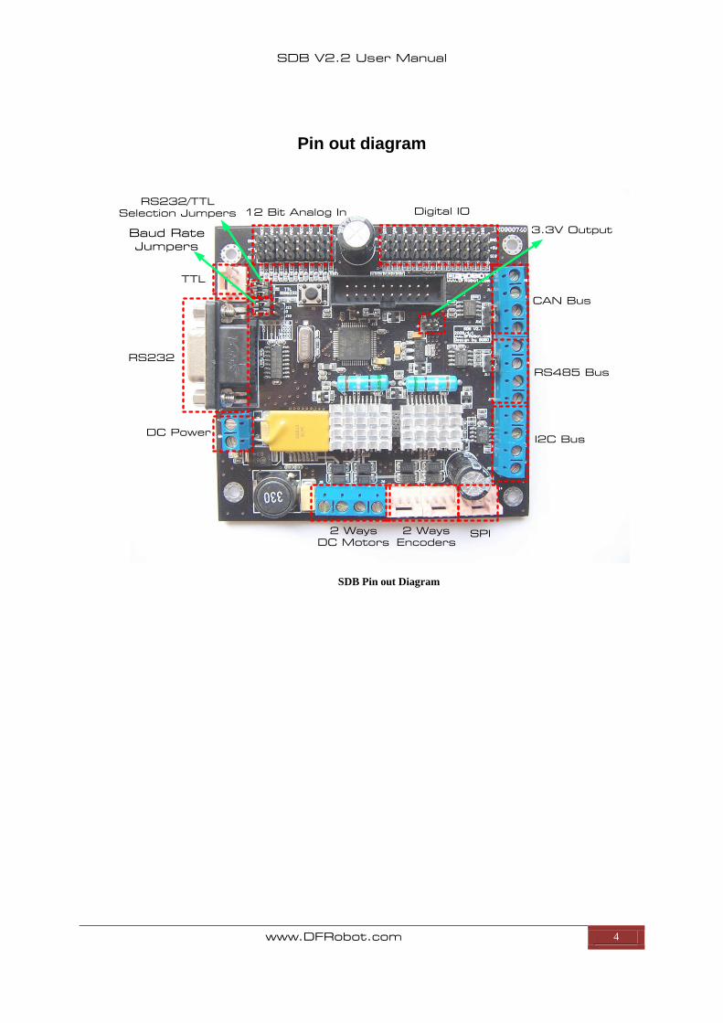
Pin out diagram
RS232
DC Power
2 Ways
DC Motors
2 Ways
Encoders
SPI
12 Bit Analog In Digital IO
CAN Bus
RS485 Bus
I2C Bus
TTL
Baud Rate
Jumpers
3.3V Output
RS232/TTL
Selection Jumpers
SDB Pin out Diagram
SDB V2.2 User Manual
www.DFRobot.com 5
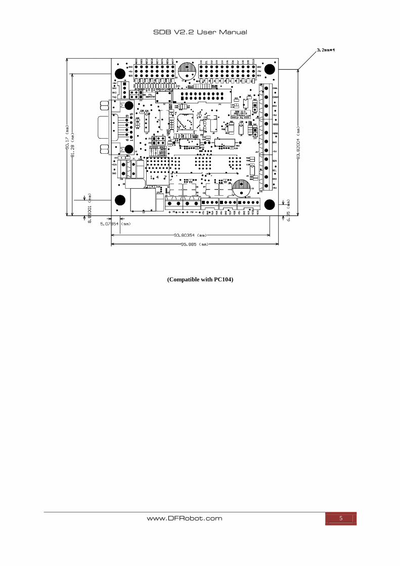
(Compatible with PC104)
SDB V2.2 User Manual
www.DFRobot.com 6
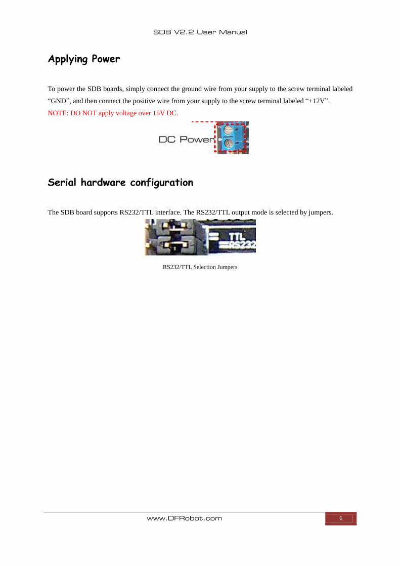
Applying Power
To power the SDB boards, simply connect the ground wire from your supply to the screw terminal labeled
“GND”, and then connect the positive wire from your supply to the screw terminal labeled “+12V”.
NOTE: DO NOT apply voltage over 15V DC.
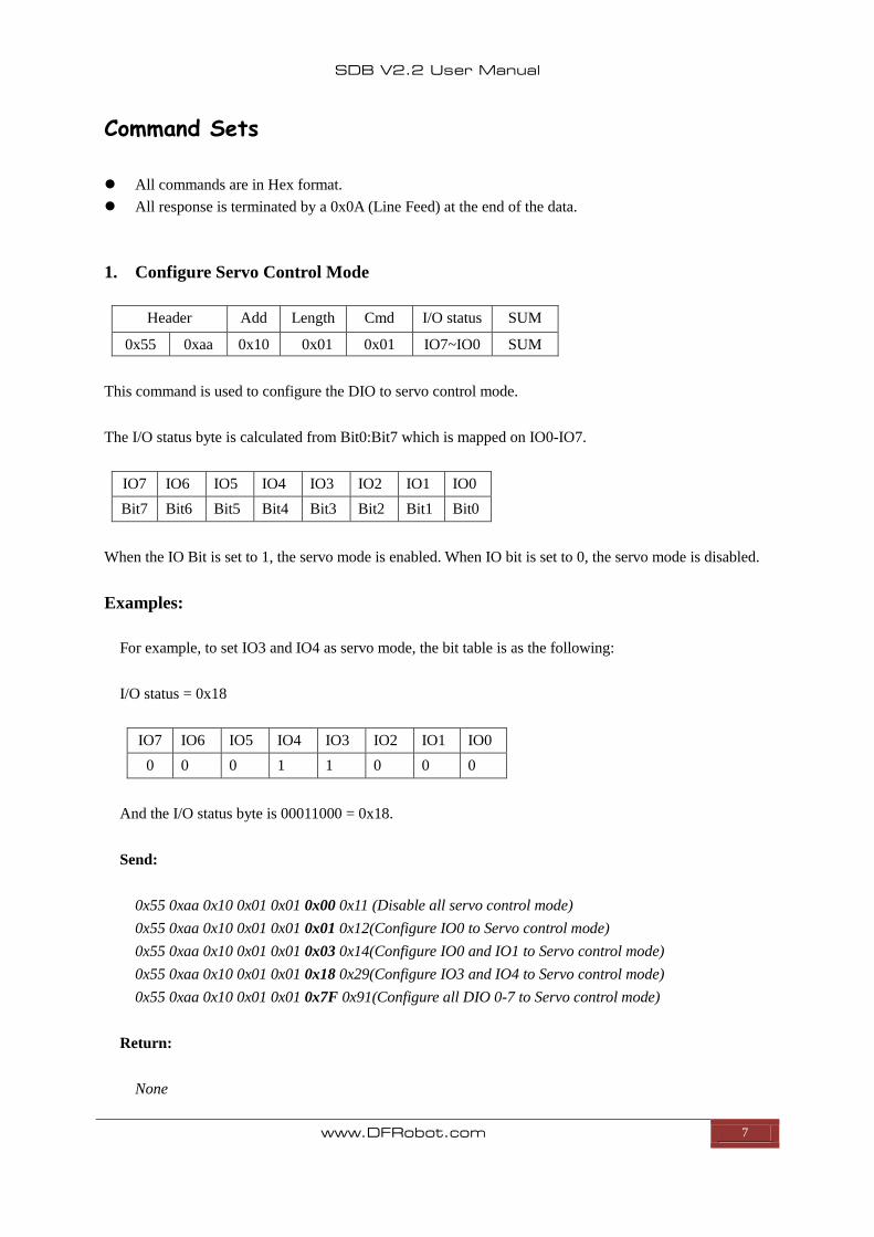
Serial hardware configuration
The SDB board supports RS232/TTL interface. The RS232/TTL output mode is selected by jumpers.
RS232/TTL Selection Jumpers
SDB V2.2 User Manual
www.DFRobot.com 7
Command Sets
All commands are in Hex format.
All response is terminated by a 0x0A (Line Feed) at the end of the data.
1. Configure Servo Control Mode
Header Add Length Cmd I/O status SUM
0x55 0xaa 0x10 0x01 0x01 IO7~IO0 SUM
This command is used to configure the DIO to servo control mode.
The I/O status byte is calculated from Bit0:Bit7 which is mapped on IO0-IO7.
IO7 IO6 IO5 IO4 IO3 IO2 IO1 IO0
Bit7 Bit6 Bit5 Bit4 Bit3 Bit2 Bit1 Bit0
When the IO Bit is set to 1, the servo mode is enabled. When IO bit is set to 0, the servo mode is disabled.
Examples:
For example, to set IO3 and IO4 as servo mode, the bit table is as the following:
I/O status = 0x18
IO7 IO6 IO5 IO4 IO3 IO2 IO1 IO0
0 0 0 1 1 0 0 0
And the I/O status byte is 00011000 = 0x18.
Send:
0x55 0xaa 0x10 0x01 0x01 0x00 0x11 (Disable all servo control mode)
0x55 0xaa 0x10 0x01 0x01 0x01 0x12(Configure IO0 to Servo control mode)
0x55 0xaa 0x10 0x01 0x01 0x03 0x14(Configure IO0 and IO1 to Servo control mode)
0x55 0xaa 0x10 0x01 0x01 0x18 0x29(Configure IO3 and IO4 to Servo control mode)
0x55 0xaa 0x10 0x01 0x01 0x7F 0x91(Configure all DIO 0-7 to Servo control mode)
Return:
None
SDB V2.2 User Manual
www.DFRobot.com 8
2. Set DIO Input/output Mode
Header Add Length Cmd I/O status H I/O status L SUM
0x55 0xaa 0x10 0x02 0x02 IO10~IO8 IO7~IO0 SUM
This command is used to set Digital Pin to input or output mode individually.
I/O status L
IO7 IO6 IO5 IO4 IO3 IO2 IO1 IO0
Bit7 Bit6 Bit5 Bit4 Bit3 Bit2 Bit1 Bit0
I/O status H
N/A N/A N/A N/A N/A IO10 IO9 IO8
N/A N/A N/A N/A N/A Bit2 Bit1 Bit0
NOTE: Before configure this DIO mode; the servo control mode must be disabled first.
Example:
To set IO 1,2,9 as output, the rest IO as input.
I/O status L =0x06
IO7 IO6 IO5 IO4 IO3 IO2 IO1 IO0
0 0 0 0 0 1 1 0
I/O status H =0x02
N/A N/A N/A N/A N/A IO10 IO9 IO8
N/A N/A N/A N/A N/A 0 1 0
Send:
0x55 0xAA 0x10 0x02 0x02 0x02 0x06 0x1B
Return:
NONE
SDB V2.2 User Manual
www.DFRobot.com 9
3. Set DIO Output
Header Add Length Cmd I/O Value H I/O Value L Sum
0x55 0xaa 0x10 0x02 0x03 IO10~IO8 IO7~IO0 SUM
I/O Value L
IO7 IO6 IO5 IO4 IO3 IO2 IO1 IO0
Bit7 Bit6 Bit5 Bit4 Bit3 Bit2 Bit1 Bit0
I/O Value H
N/A N/A N/A N/A N/A IO10 IO9 IO8
N/A N/A N/A N/A N/A Bit2 Bit1 Bit0
When the Bit is set to 1, the output is HIGH, When the Bit is set to 0, the output is LOW
NOTE: If one of the DIO is configured as Digital Input Mode, the command to set its output will be
invalid.
Example:
Send:
0x55 0xAA 0x10 0x01 0x01 0x00 0x11 (Disable servo control mode)
0x55 0xAA 0x10 0x02 0x02 0x00 0x00 0x13 (Configure IO0-10 as output mode)
0x55 0xAA 0x10 0x02 0x03 0x55 0x55 SUM (Set IO Output 0x55 0x55)
Tips: It is encouraged to disable servo control mode before performing any operations on DIO
Return:
NONE
SDB V2.2 User Manual
www.DFRobot.com 10
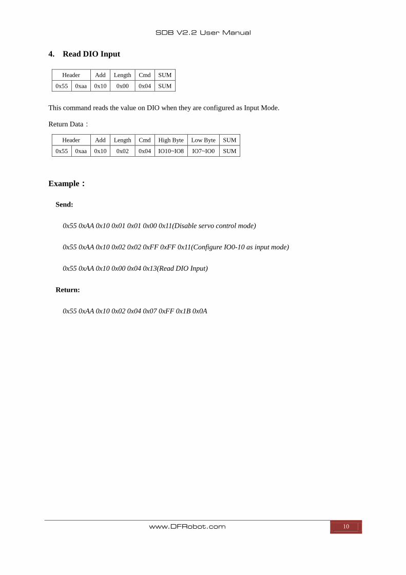
4. Read DIO Input
Header Add Length Cmd SUM
0x55 0xaa 0x10 0x00 0x04 SUM
This command reads the value on DIO when they are configured as Input Mode.
Return Data:
Header Add Length Cmd High Byte Low Byte SUM
0x55 0xaa 0x10 0x02 0x04 IO10~IO8 IO7~IO0 SUM
Example:
Send:
0x55 0xAA 0x10 0x01 0x01 0x00 0x11(Disable servo control mode)
0x55 0xAA 0x10 0x02 0x02 0xFF 0xFF 0x11(Configure IO0-10 as input mode)
0x55 0xAA 0x10 0x00 0x04 0x13(Read DIO Input)
Return:
0x55 0xAA 0x10 0x02 0x04 0x07 0xFF 0x1B 0x0A
SDB V2.2 User Manual
www.DFRobot.com 11
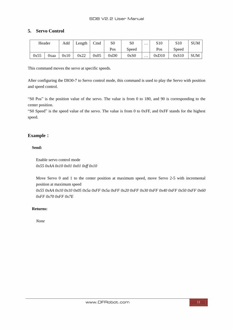
5. Servo Control
Header Add Length Cmd S0
Pos
S0
Speed
… S10
Pos
S10
Speed
SUM
0x55 0xaa 0x10 0x22 0x05 0xD0 0xS0 … 0xD10 0xS10 SUM
This command moves the servo at specific speeds.
After configuring the DIO0-7 to Servo control mode, this command is used to play the Servo with position
and speed control.
“S0 Pos” is the position value of the servo. The value is from 0 to 180, and 90 is corresponding to the
center position.
“S0 Speed” is the speed value of the servo. The value is from 0 to 0xFF, and 0xFF stands for the highest
speed.
Example:
Send:
Enable servo control mode
0x55 0xAA 0x10 0x01 0x01 0xff 0x10
Move Servo 0 and 1 to the center position at maximum speed, move Servo 2-5 with incremental
position at maximum speed
0x55 0xAA 0x10 0x10 0x05 0x5a 0xFF 0x5a 0xFF 0x20 0xFF 0x30 0xFF 0x40 0xFF 0x50 0xFF 0x60
0xFF 0x70 0xFF 0x7E
Returns:
None
SDB V2.2 User Manual
www.DFRobot.com 12
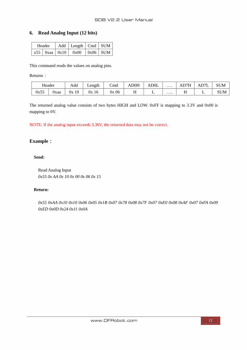
6. Read Analog Input (12 bits)
Header Add Length Cmd SUM
x55 0xaa 0x10 0x00 0x06 SUM
This command reads the values on analog pins.
Returns:
Header Add Length Cmd AD0H AD0L …. AD7H AD7L SUM
0x55 0xaa 0x 10 0x 16 0x 06 H L ….. H L SUM
The returned analog value consists of two bytes HIGH and LOW. 0xFF is mapping to 3.3V and 0x00 is
mapping to 0V.
NOTE: If the analog input exceeds 3.36V, the returned data may not be correct.
Example:
Send:
Read Analog Input
0x55 0x AA 0x 10 0x 00 0x 06 0x 15
Return:
0x55 0xAA 0x10 0x10 0x06 0x05 0x1B 0x07 0x78 0x08 0x7F 0x07 0xE0 0x08 0xAF 0x07 0xFA 0x09
0xED 0x0D 0x24 0x11 0x0A
SDB V2.2 User Manual
www.DFRobot.com 13
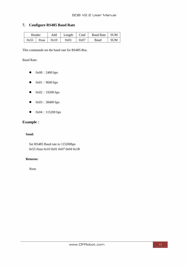
7. Configure RS485 Baud Rate
Header Add Length Cmd Baud Rate SUM
0x55 0xaa 0x10 0x01 0x07 Baud SUM
This commands set the baud rate for RS485 Bus.
Baud Rate:
0x00:2400 bps
0x01:9600 bps
0x02:19200 bps
0x03:38400 bps
0x04:115200 bps
Example:
Send:
Set RS485 Baud rate to 115200bps
0x55 0xaa 0x10 0x01 0x07 0x04 0x1B
Returns:
None
SDB V2.2 User Manual
www.DFRobot.com 14
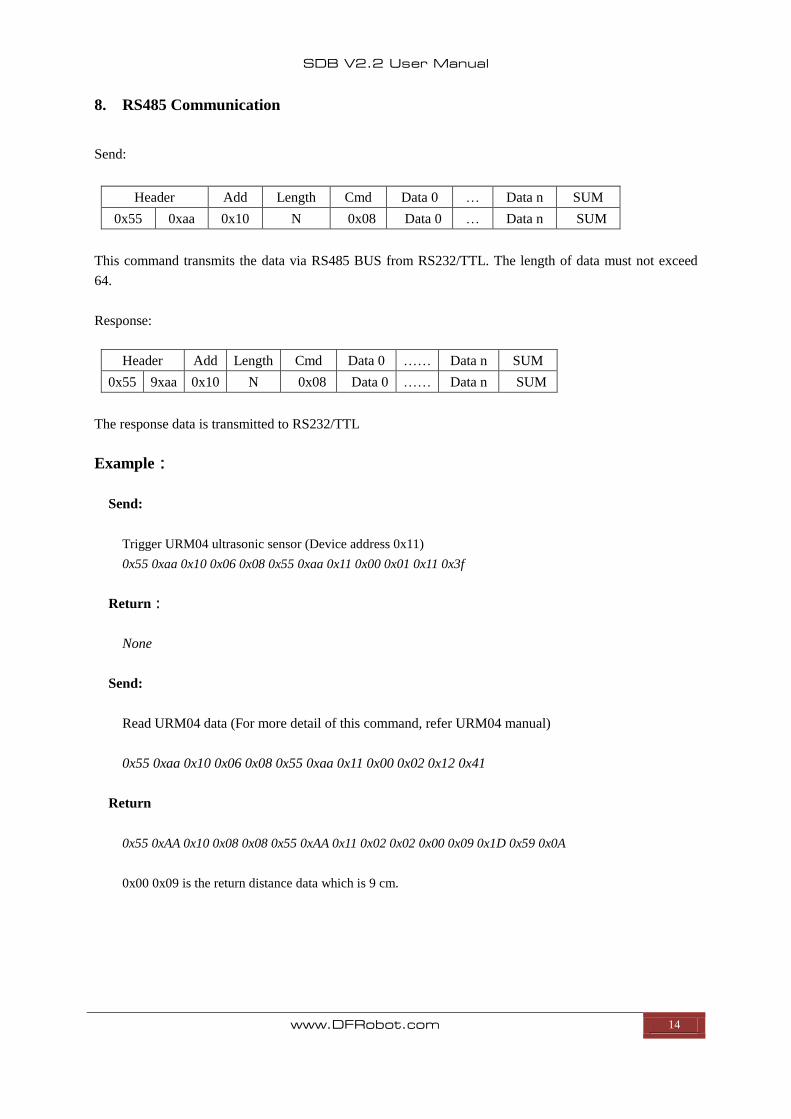
8. RS485 Communication
Send:
Header Add Length Cmd Data 0 … Data n SUM
0x55 0xaa 0x10 N 0x08 Data 0 … Data n SUM
This command transmits the data via RS485 BUS from RS232/TTL. The length of data must not exceed
64.
Response:
Header Add Length Cmd Data 0 …… Data n SUM
0x55 9xaa 0x10 N 0x08 Data 0 …… Data n SUM
The response data is transmitted to RS232/TTL
Example:
Send:
Trigger URM04 ultrasonic sensor (Device address 0x11)
0x55 0xaa 0x10 0x06 0x08 0x55 0xaa 0x11 0x00 0x01 0x11 0x3f
Return:
None
Send:
Read URM04 data (For more detail of this command, refer URM04 manual)
0x55 0xaa 0x10 0x06 0x08 0x55 0xaa 0x11 0x00 0x02 0x12 0x41
Return
0x55 0xAA 0x10 0x08 0x08 0x55 0xAA 0x11 0x02 0x02 0x00 0x09 0x1D 0x59 0x0A
0x00 0x09 is the return distance data which is 9 cm.
SDB V2.2 User Manual
www.DFRobot.com 15
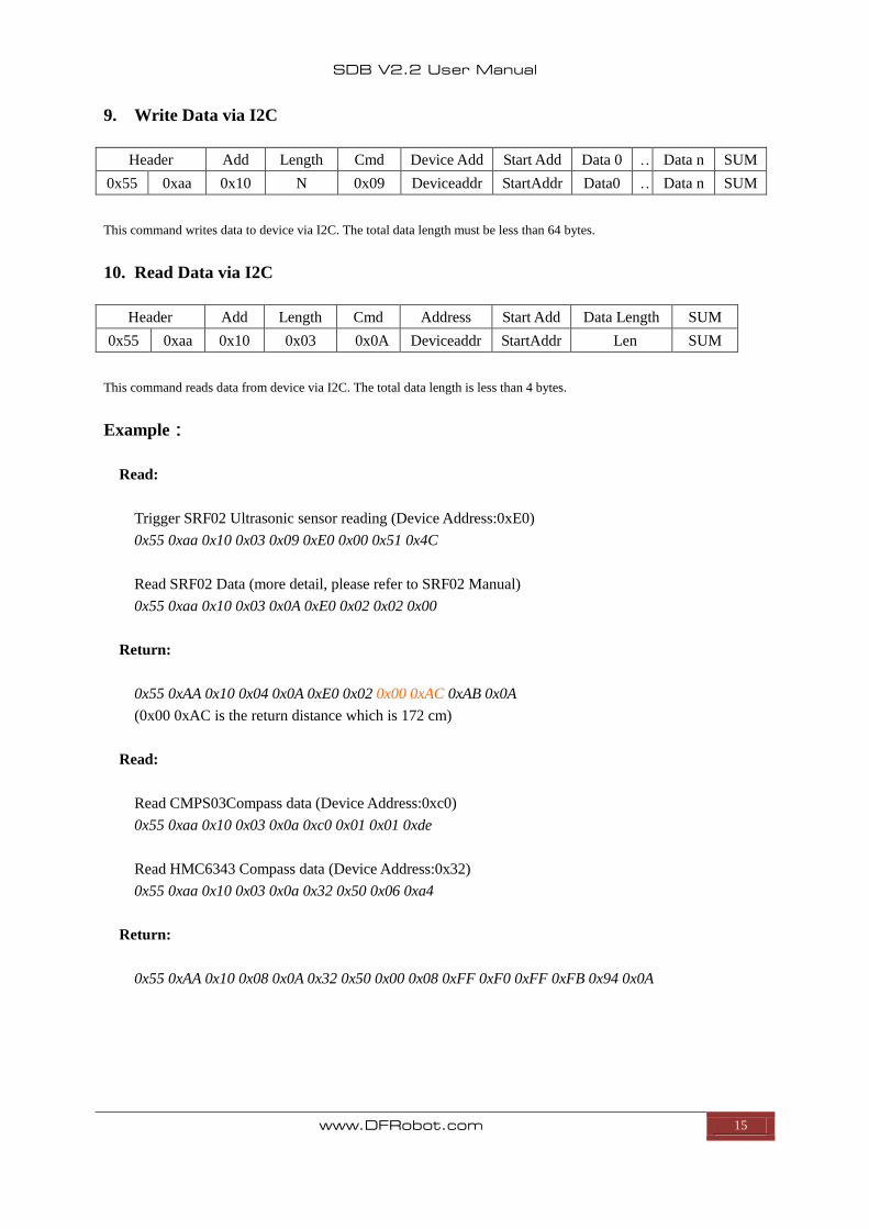
9. Write Data via I2C
Header Add Length Cmd Device Add Start Add Data 0 … Data n SUM
0x55 0xaa 0x10 N 0x09 Deviceaddr StartAddr Data0 … Data n SUM
This command writes data to device via I2C. The total data length must be less than 64 bytes.
10. Read Data via I2C
Header Add Length Cmd Address Start Add Data Length SUM
0x55 0xaa 0x10 0x03 0x0A Deviceaddr StartAddr Len SUM
This command reads data from device via I2C. The total data length is less than 4 bytes.
Example:
Read:
Trigger SRF02 Ultrasonic sensor reading (Device Address:0xE0)
0x55 0xaa 0x10 0x03 0x09 0xE0 0x00 0x51 0x4C
Read SRF02 Data (more detail, please refer to SRF02 Manual)
0x55 0xaa 0x10 0x03 0x0A 0xE0 0x02 0x02 0x00
Return:
0x55 0xAA 0x10 0x04 0x0A 0xE0 0x02 0x00 0xAC 0xAB 0x0A
(0x00 0xAC is the return distance which is 172 cm)
Read:
Read CMPS03Compass data (Device Address:0xc0)
0x55 0xaa 0x10 0x03 0x0a 0xc0 0x01 0x01 0xde
Read HMC6343 Compass data (Device Address:0x32)
0x55 0xaa 0x10 0x03 0x0a 0x32 0x50 0x06 0xa4
Return:
0x55 0xAA 0x10 0x08 0x0A 0x32 0x50 0x00 0x08 0xFF 0xF0 0xFF 0xFB 0x94 0x0A
SDB V2.2 User Manual
www.DFRobot.com 16
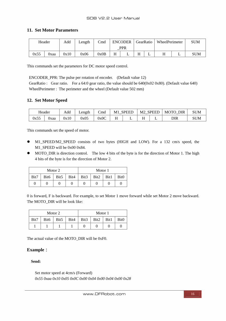
11. Set Motor Parameters
Header Add Length Cmd ENCODER
_PPR
GearRatio WheelPerimeter SUM
0x55 0xaa 0x10 0x06 0x0B H L H L H L SUM
This commands set the parameters for DC motor speed control.
ENCODER_PPR: The pulse per rotation of encoder. (Default value 12)
GearRatio : Gear ratio. For a 64:0 gear ratio, the value should be 640(0x02 0x80). (Default value 640)
WheelPerimeter : The perimeter and the wheel (Default value 502 mm)
12. Set Motor Speed
Header Add Length Cmd M1_SPEED M2_SPEED MOTO_DIR SUM
0x55 0xaa 0x10 0x05 0x0C H L H L DIR SUM
This commands set the speed of motor.
M1_SPEED/M2_SPEED consists of two bytes (HIGH and LOW). For a 132 cm/s speed, the
M1_SPEED will be 0x00 0x84.
MOTO_DIR is direction control. The low 4 bits of the byte is for the direction of Motor 1. The high
4 bits of the byte is for the direction of Motor 2.
Motor 2 Motor 1
Bit7 Bit6 Bit5 Bit4 Bit3 Bit2 Bit1 Bit0
0 0 0 0 0 0 0 0
0 is forward, F is backward. For example, to set Motor 1 move forward while set Motor 2 move backward.
The MOTO_DIR will be look like:
Motor 2 Motor 1
Bit7 Bit6 Bit5 Bit4 Bit3 Bit2 Bit1 Bit0
1 1 1 1 0 0 0 0
The actual value of the MOTO_DIR will be 0xF0.
Example:
Send:
Set motor speed at 4cm/s (Forward)
0x55 0xaa 0x10 0x05 0x0C 0x00 0x04 0x00 0x04 0x00 0x28
SDB V2.2 User Manual
www.DFRobot.com 17
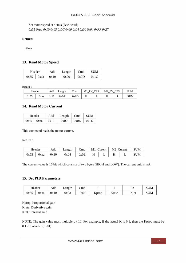
Set motor speed at 4cm/s (Backward)
0x55 0xaa 0x10 0x05 0x0C 0x00 0x04 0x00 0x04 0xFF 0x27
Return:
None
13. Read Motor Speed
Header Add Length Cmd SUM
0x55 0xaa 0x10 0x00 0x0D 0x1C
Return:
Header Add Length Cmd M1_PV_CPS M2_PV_CPS SUM
0x55 0xaa 0x10 0x04 0x0D H L H L SUM
14. Read Motor Current
Header Add Length Cmd SUM
0x55 0xaa 0x10 0x00 0x0E 0x1D
This command reads the motor current.
Return:
Header Add Length Cmd M1_Curent M2_Curent SUM
0x55 0xaa 0x10 0x04 0x0E H L H L SUM
The current value is 16 bit which consists of two bytes (HIGH and LOW). The current unit is mA.
15. Set PID Parameters
Header Add Length Cmd P I D SUM
0x55 0xaa 0x10 0x03 0x0F Kprop Krate Kint SUM
Kprop: Proportional gain
Krate: Derivative gain
Kint : Integral gain
NOTE: The gain value must multiple by 10. For example, if the actual K is 0.1, then the Kprop must be
0.1x10 which 1(0x01).
SDB V2.2 User Manual
www.DFRobot.com 18
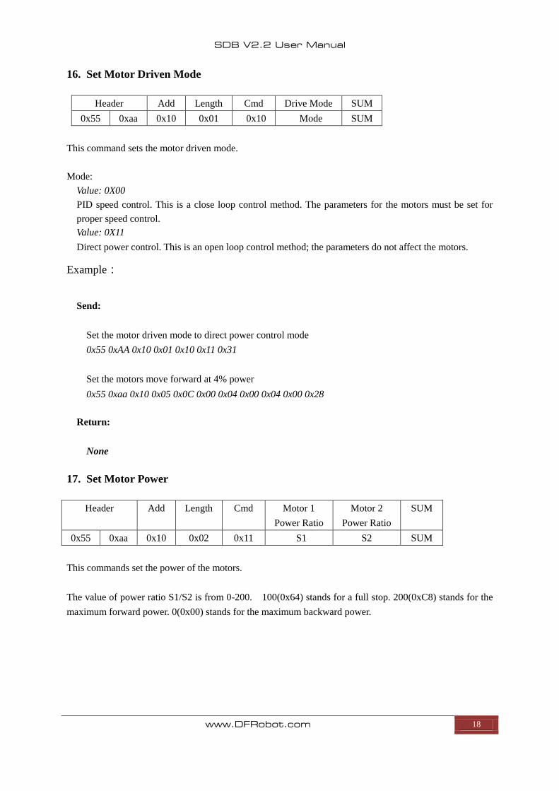
16. Set Motor Driven Mode
Header Add Length Cmd Drive Mode SUM
0x55 0xaa 0x10 0x01 0x10 Mode SUM
This command sets the motor driven mode.
Mode:
Value: 0X00
PID speed control. This is a close loop control method. The parameters for the motors must be set for
proper speed control.
Value: 0X11
Direct power control. This is an open loop control method; the parameters do not affect the motors.
Example:
Send:
Set the motor driven mode to direct power control mode
0x55 0xAA 0x10 0x01 0x10 0x11 0x31
Set the motors move forward at 4% power
0x55 0xaa 0x10 0x05 0x0C 0x00 0x04 0x00 0x04 0x00 0x28
Return:
None
17. Set Motor Power
Header Add Length Cmd Motor 1
Power Ratio
Motor 2
Power Ratio
SUM
0x55 0xaa 0x10 0x02 0x11 S1 S2 SUM
This commands set the power of the motors.
The value of power ratio S1/S2 is from 0-200. 100(0x64) stands for a full stop. 200(0xC8) stands for the
maximum forward power. 0(0x00) stands for the maximum backward power.
SDB V2.2 User Manual
www.DFRobot.com 19
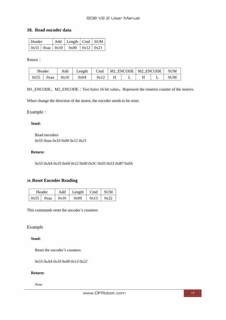
18. Read encoder data
Header Add Length Cmd SUM
0x55 0xaa 0x10 0x00 0x12 0x21
Return:
Header Add Length Cmd M1_ENCODE M2_ENCODE SUM
0x55 0xaa 0x10 0x04 0x12 H L H L SUM
M1_ENCODE、M2_ENCODE:Two bytes 16 bit value。Represent the rotation counter of the motors.
When change the direction of the motor, the encoder needs to be reset.
Example:
Send:
Read encoders
0x55 0xaa 0x10 0x00 0x12 0x21
Return:
0x55 0xAA 0x10 0x04 0x12 0x00 0x3C 0x03 0x53 0xB7 0x0A
19. Reset Encoder Reading
Header Add Length Cmd SUM
0x55 0xaa 0x10 0x00 0x13 0x22
This commands reset the encoder’s counters
Example
Send:
Reset the encoder’s counters
0x55 0xAA 0x10 0x00 0x13 0x22
Return:
None
SDB V2.2 User Manual
www.DFRobot.com 20
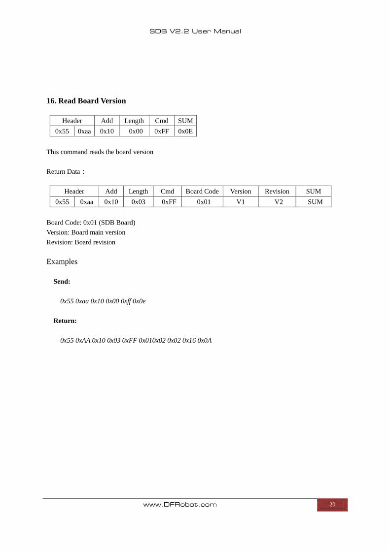
16. Read Board Version
Header Add Length Cmd SUM
0x55 0xaa 0x10 0x00 0xFF 0x0E
This command reads the board version
Return Data:
Header Add Length Cmd Board Code Version Revision SUM
0x55 0xaa 0x10 0x03 0xFF 0x01 V1 V2 SUM
Board Code: 0x01 (SDB Board)
Version: Board main version
Revision: Board revision
Examples
Send:
0x55 0xaa 0x10 0x00 0xff 0x0e
Return:
0x55 0xAA 0x10 0x03 0xFF 0x010x02 0x02 0x16 0x0A
SDB V2.2 User Manual
www.DFRobot.com 21
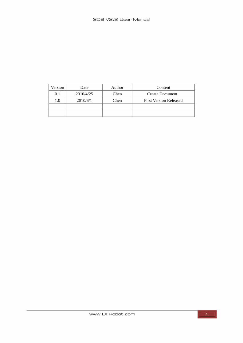
Version Date Author Content
0.1 2010/4/25 Chen Create Document
1.0 2010/6/1 Chen First Version Released