Embed Size (px)
Citation preview
Applications• Fiber-coupled Illumination
• Architectural and Entertainment Lighting
• Medical Lighting
• Machine Vision
• Spot Lighting
• Displays and Signage
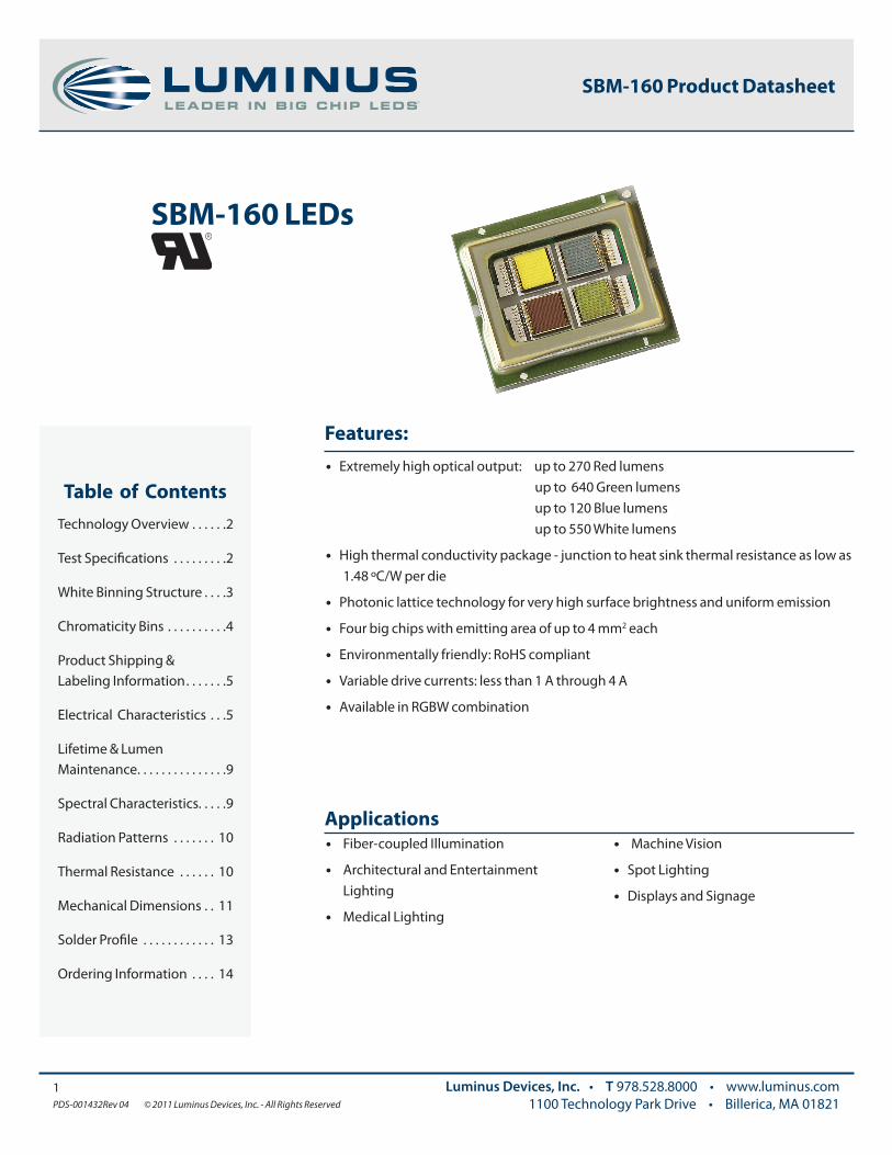
Features:• Extremely high optical output: up to 270 Red lumens up to 640 Green lumens up to 120 Blue lumens up to 550 White lumens
• High thermal conductivity package - junction to heat sink thermal resistance as low as 1.48 ºC/W per die
• Photonic lattice technology for very high surface brightness and uniform emission
• Four big chips with emitting area of up to 4 mm2 each
• Environmentally friendly: RoHS compliant
• Variable drive currents: less than 1 A through 4 A
• Available in RGBW combination
Table of ContentsTechnology Overview . . . . . .2
Test Specifications . . . . . . . . .2
White Binning Structure . . . .3
Chromaticity Bins . . . . . . . . . .4
Product Shipping & Labeling Information . . . . . . .5
Electrical Characteristics . . .5
Lifetime & Lumen Maintenance . . . . . . . . . . . . . . .9
Spectral Characteristics. . . . .9
Radiation Patterns . . . . . . . 10
Thermal Resistance . . . . . . 10
Mechanical Dimensions . . 11
Solder Profile . . . . . . . . . . . . 13
Ordering Information . . . . 14
1PDS-001432Rev 04 © 2011 Luminus Devices, Inc. - All Rights Reserved
Luminus Devices, Inc. • T 978.528.8000 • www.luminus.com1100 Technology Park Drive • Billerica, MA 01821
SBM-160 LEDs
SBM-160 Product Datasheet
Testing Temperature
Luminus core board products are typically measured in such a way that the characteristics reported agree with how the devices will actually perform when incorporated into a system. This measurement is accomplished by mounting the devices on a 40ºC heat sink and allowing the device to reach thermal equilibrium while fully powered. Only after the device reaches equilibrium are the measurements taken. This method of measurement ensures that Luminus Big Chip LEDs perform in the field just as they are specified.
Multiple Operating Points
The tables on the following pages provide typical optical and electrical characteristics. Since the LEDs can be operated over a wide range of drive conditions (currents from less than 1A to 4A, and duty cycle from <1% to 100%), multiple drive conditions are listed.
Understanding Big Chip LED Test Specifications
Every Luminus LED is fully tested to ensure that it meets the high quality standards expected from Luminus’ products.
2PDS-001432Rev 04 © 2011 Luminus Devices, Inc. - All Rights Reserved
Luminus Devices, Inc. • T 978.528.8000 • www.luminus.com1100 Technology Park Drive • Billerica, MA 01821
SBM-160 Product Datasheet
Photonic Lattice Technology
Luminus’ photonic lattice technology enables large area LED chips with uniform brightness over the entire LED chip surface. The optical power and brightness produced by these large monolithic chips enable solutions which replace arc and halogen lamps where arrays of traditional high power LEDs cannot.
For red, green and blue LEDs, the photonic lattice structures extract more light and create radiation patterns that are more collimated than traditional LEDs. Having higher collimation from the source increases optical collection efficiencies and simplifies optical designs.
Packaging Technology
Thermal management is critical in high power LED applications. With a thermal resistance from junction to heat sink of 1.48º C/W per chip. Luminus SBM-160 LEDs have the lowest thermal resistance of any LED on the market. This allows the LED to be driven at higher current densities while maintaining a low junction temperature, thereby resulting in brighter solutions
and longer lifetimes.
Reliability
Designed from the ground up, Luminus Big Chip LEDs are one of the most reliable light sources in the world today. Big Chip LEDs have passed a rigorous suite of environmental and mechanical stress tests, including mechanical shock, vibration, temperature cycling and humidity, and have been fully qualified for use in extreme high power and high current applications. With very low failure rates and median lifetimes that typically exceed 60,000 hours, Luminus Big Chip LEDs are ready for even the most demanding applications.
Environmental Benefits
Luminus LEDs help reduce power consumption and the amount of hazardous waste entering the environment. All Big Chip LED products manufactured by Luminus are RoHS compliant and free of hazardous materials, including lead and mercury.
Technology Overview
Luminus Big Chip LEDs™ benefit from a suite of innovations in the fields of chip technology, packaging and thermal management. These breakthroughs allow illumination engineers and designers to achieve solutions that are high brightness and high efficiency.
0.380
0.355
0.330
0.305
0.2800.270 0.295 0.320 0.345 0.370
CIEx
CIEy
BB Locus
6500
5700
DE
EF
EH
H4
J4
H3
J3
DJ
F4
G4
G3
F3
DF
DG
3PDS-001432Rev 04 © 2011 Luminus Devices, Inc. - All Rights Reserved
Luminus Devices, Inc. • T 978.528.8000 • www.luminus.com1100 Technology Park Drive • Billerica, MA 01821
*Note: Luminus maintains a +/- 6% tolerance on flux measurements.
Flux Bins
SBM-160 Product Datasheet
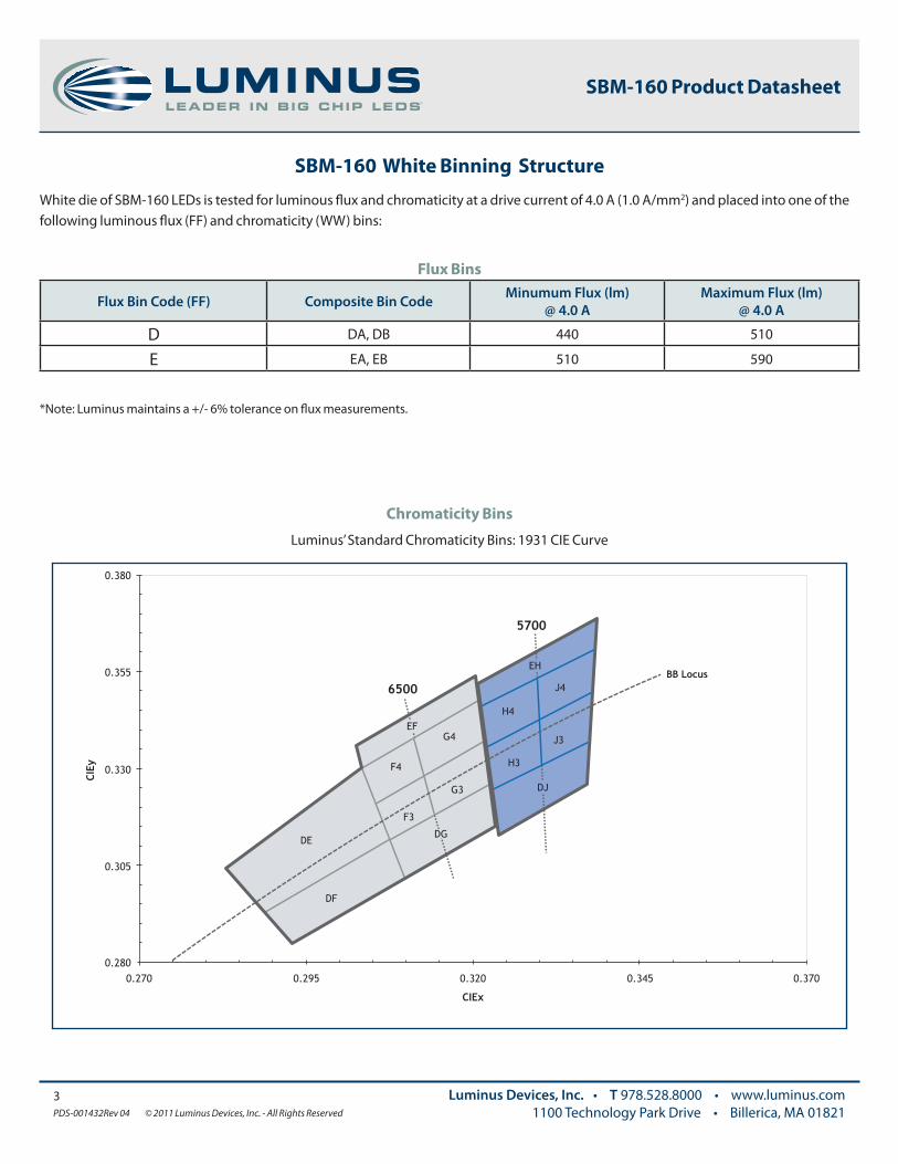
Chromaticity Bins
Luminus’ Standard Chromaticity Bins: 1931 CIE Curve
SBM-160 White Binning Structure
White die of SBM-160 LEDs is tested for luminous flux and chromaticity at a drive current of 4.0 A (1.0 A/mm2) and placed into one of the following luminous flux (FF) and chromaticity (WW) bins:
Flux Bin Code (FF) Composite Bin Code Minumum Flux (lm) @ 4.0 A
Maximum Flux (lm) @ 4.0 A
D DA, DB 440 510
E EA, EB 510 590
4PDS-001432Rev 04 © 2011 Luminus Devices, Inc. - All Rights Reserved
Luminus Devices, Inc. • T 978.528.8000 • www.luminus.com1100 Technology Park Drive • Billerica, MA 01821
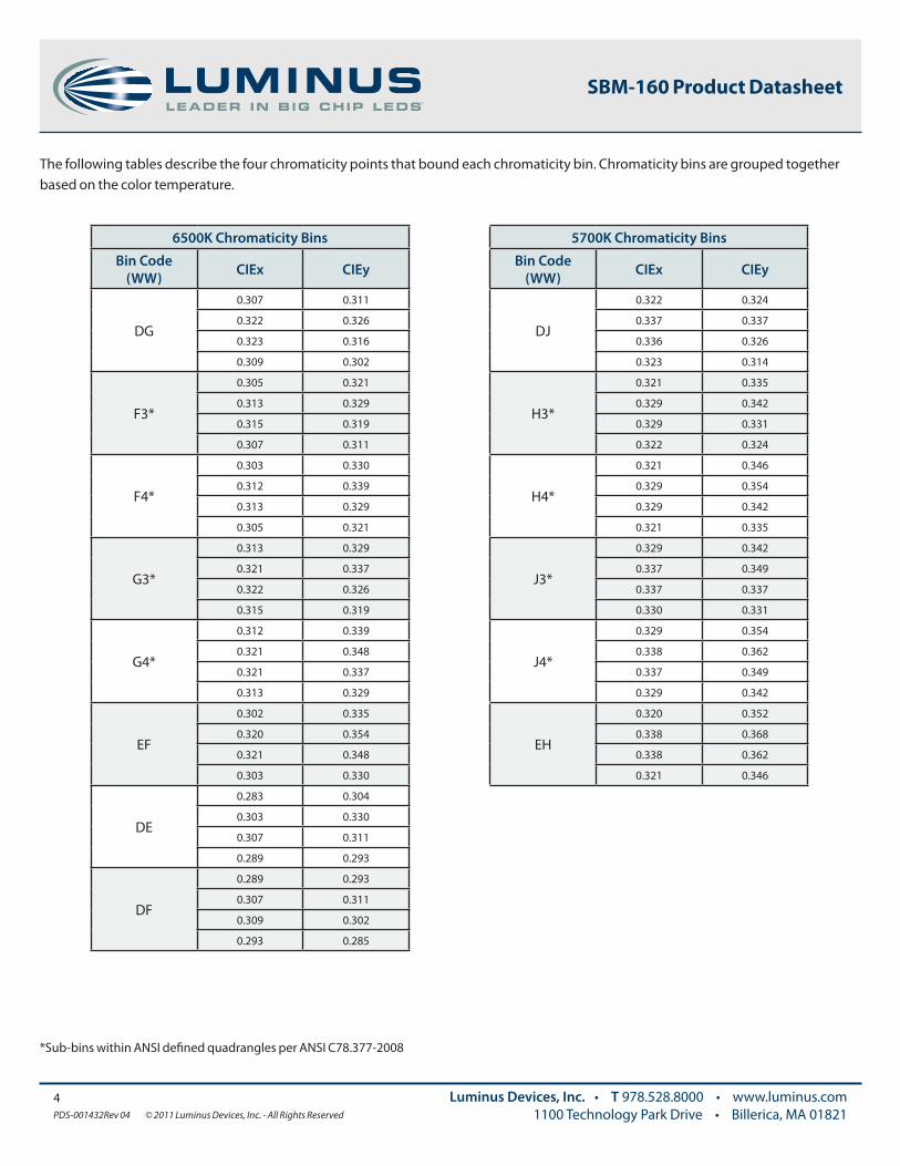
*Sub-bins within ANSI defined quadrangles per ANSI C78.377-2008
The following tables describe the four chromaticity points that bound each chromaticity bin. Chromaticity bins are grouped together based on the color temperature.
SBM-160 Product Datasheet
6500K Chromaticity Bins
Bin Code(WW) CIEx CIEy
DG
0.307 0.311
0.322 0.326
0.323 0.316
0.309 0.302
F3*
0.305 0.321
0.313 0.329
0.315 0.319
0.307 0.311
F4*
0.303 0.330
0.312 0.339
0.313 0.329
0.305 0.321
G3*
0.313 0.329
0.321 0.337
0.322 0.326
0.315 0.319
G4*
0.312 0.339
0.321 0.348
0.321 0.337
0.313 0.329
EF
0.302 0.335
0.320 0.354
0.321 0.348
0.303 0.330
DE
0.283 0.304
0.303 0.330
0.307 0.311
0.289 0.293
DF
0.289 0.293
0.307 0.311
0.309 0.302
0.293 0.285
5700K Chromaticity Bins
Bin Code(WW) CIEx CIEy
DJ
0.322 0.324
0.337 0.337
0.336 0.326
0.323 0.314
H3*
0.321 0.335
0.329 0.342
0.329 0.331
0.322 0.324
H4*
0.321 0.346
0.329 0.354
0.329 0.342
0.321 0.335
J3*
0.329 0.342
0.337 0.349
0.337 0.337
0.330 0.331
J4*
0.329 0.354
0.338 0.362
0.337 0.349
0.329 0.342
EH
0.320 0.352
0.338 0.368
0.338 0.362
0.321 0.346
5PDS-001432Rev 04 © 2011 Luminus Devices, Inc. - All Rights Reserved
Luminus Devices, Inc. • T 978.528.8000 • www.luminus.com1100 Technology Park Drive • Billerica, MA 01821
Note : Some flux and chromaticity bins may have limited availability. Application specific bin kits, consisting of multiple bins, may be available.
For ordering information, please refer to page 14 and reference PDS-001792: SBM-160 Binning & Labeling document.
Example:
The part number SBM-160-RGBW-H41-EA-G4 refers to a RGBW, SBM-160 emitter, with a flux range of 510-550 lumens and a chromaticity value within the box defined by the four points (0.313, 0.338), (0.321, 0.348), (0.322, 0.336), (0.312, 0.328).
Product Family Chip Area Color Package Configuration Flux Bin Chromaticity Bin
Surface Mount (window) 16.0 mm2
R: RedG: GreenB: Blue
W: White
Internal Code See page 3 for bins See page 4 for bins
SBM 160 RGBW H41 FF WW
SBM-160 Product Datasheet
Product Shipping & Labeling Information
All SBM-160 products are packaged and labeled with their respective bin as outlined in the tables on pages 3 & 4. When shipped, each package will only contain one bin. The part number designation is as follows:
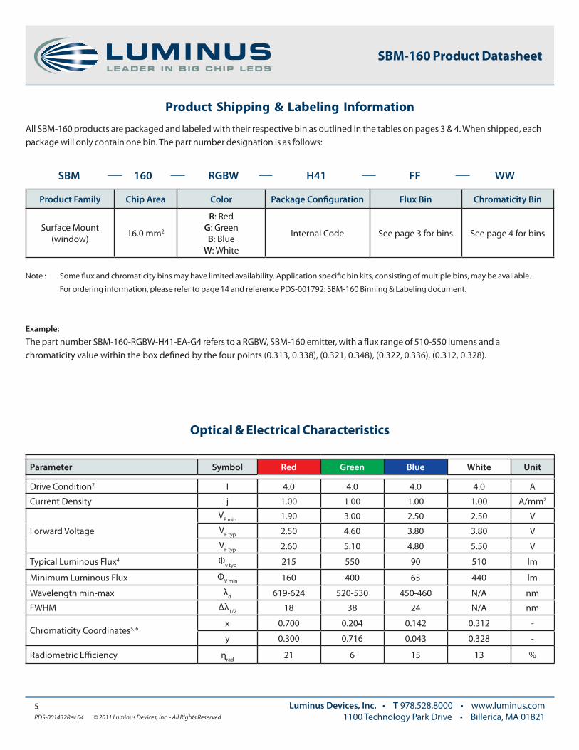
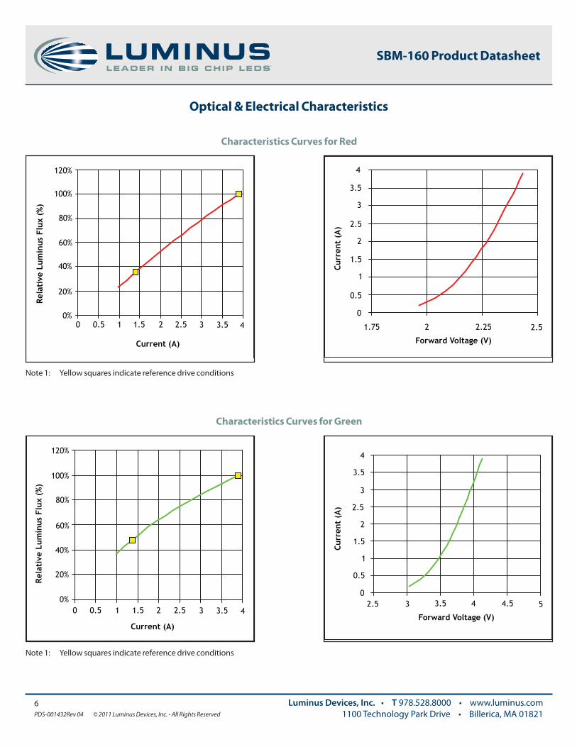
Optical & Electrical Characteristics
Parameter Symbol Red Green Blue White Unit
Drive Condition2 I 4.0 4.0 4.0 4.0 A
Current Density j 1.00 1.00 1.00 1.00 A/mm2
Forward Voltage
VF min 1.90 3.00 2.50 2.50 VVF typ 2.50 4.60 3.80 3.80 VVF typ 2.60 5.10 4.80 5.50 V
Typical Luminous Flux4 Φv typ 215 550 90 510 lm
Minimum Luminous Flux ΦV min 160 400 65 440 lm
Wavelength min-max λd 619-624 520-530 450-460 N/A nm
FWHM Δλ1/2 18 38 24 N/A nm
Chromaticity Coordinates5, 6x 0.700 0.204 0.142 0.312 -
y 0.300 0.716 0.043 0.328 -
Radiometric Efficiency ηrad 21 6 15 13 %
6PDS-001432Rev 04 © 2011 Luminus Devices, Inc. - All Rights Reserved
Luminus Devices, Inc. • T 978.528.8000 • www.luminus.com1100 Technology Park Drive • Billerica, MA 01821
SBM-160 Product Datasheet
Optical & Electrical Characteristics
0%
20%
40%
60%
80%
100%
120%
Rela
tive
Lum
inus
Flu
x (%
)
3.5 4
Current (A)
32.521.510.50
Note 1: Yellow squares indicate reference drive conditions
Characteristics Curves for Red
0.5
1
1.5
2
2.5
3
3.5
4
Curr
ent
(A)
0
2.5
Forward Voltage (V)
2.2521.75
0%
20%
40%
60%
80%
100%
120%
Rela
tive
Lum
inus
Flu
x (%
)
3.5 4
Current (A)
32.521.510.50
Note 1: Yellow squares indicate reference drive conditions
Characteristics Curves for Green
0.5
1
1.5
2
2.5
3
3.5
4
Curr
ent
(A)
0 5
Forward Voltage (V)
3.532.5 4 4.5
Optical & Electrical Characteristics
7PDS-001432Rev 04 © 2011 Luminus Devices, Inc. - All Rights Reserved
Luminus Devices, Inc. • T 978.528.8000 • www.luminus.com1100 Technology Park Drive • Billerica, MA 01821
SBM-160 Product Datasheet
0%
20%
40%
60%
80%
100%
120%
Rela
tive
Lum
inus
Flu
x (%
)
3.5 4
Current (A)
32.521.510.50
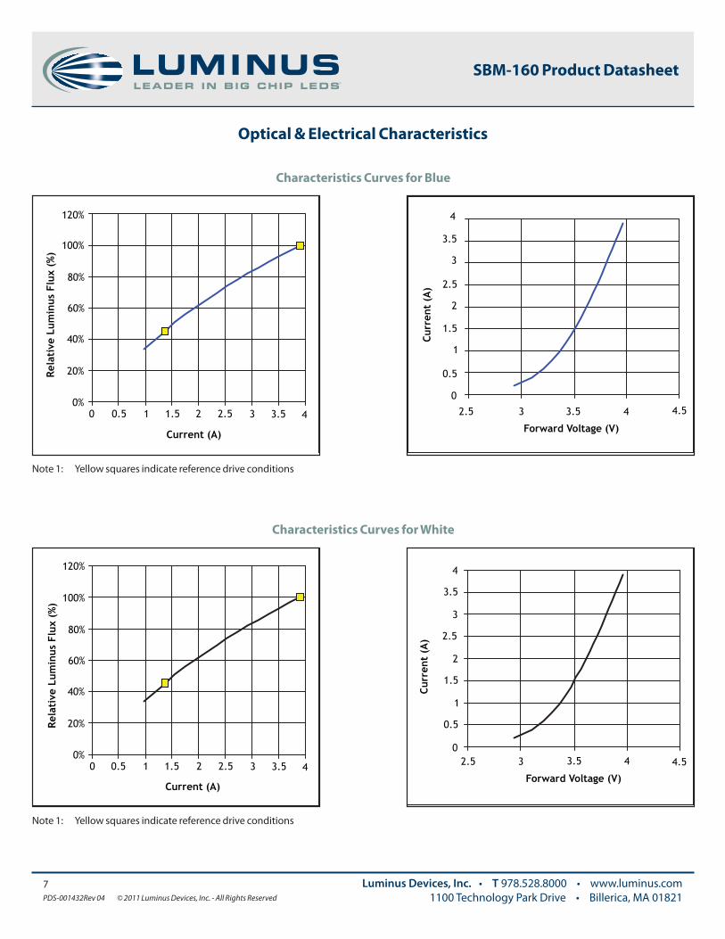
Note 1: Yellow squares indicate reference drive conditions
Characteristics Curves for Blue
0.5
1
1.5
2
2.5
3
3.5
4
Curr
ent
(A)
0 4.5
Forward Voltage (V)
432.5 3.5
0%
20%
40%
60%
80%
100%
120%
Rela
tive
Lum
inus
Flu
x (%
)
3.5 4
Current (A)
32.521.510.50
Note 1: Yellow squares indicate reference drive conditions
Characteristics Curves for White
0.5
1
1.5
2
2.5
3
3.5
4
Curr
ent
(A)
0 4.5
Forward Voltage (V)
3.532.5 4
Optical & Electrical Characteristics
8PDS-001432Rev 04 © 2011 Luminus Devices, Inc. - All Rights Reserved
Luminus Devices, Inc. • T 978.528.8000 • www.luminus.com1100 Technology Park Drive • Billerica, MA 01821
SBM-160 Product Datasheet
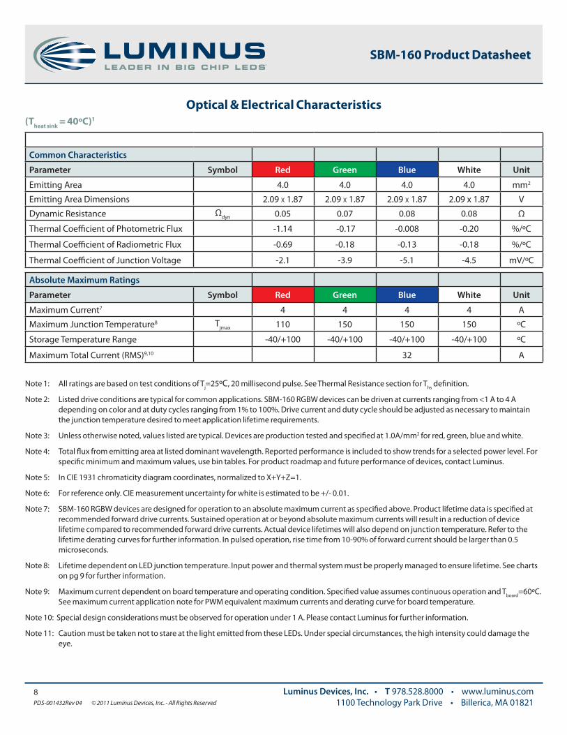
(Theat sink = 40ºC)1
Common Characteristics
Parameter Symbol Red Green Blue White Unit
Emitting Area 4.0 4.0 4.0 4.0 mm2
Emitting Area Dimensions 2.09 x 1.87 2.09 x 1.87 2.09 x 1.87 2.09 x 1.87 V
Dynamic Resistance Ωdyn 0.05 0.07 0.08 0.08 Ω
Thermal Coefficient of Photometric Flux -1.14 -0.17 -0.008 -0.20 %/ºC
Thermal Coefficient of Radiometric Flux -0.69 -0.18 -0.13 -0.18 %/ºC
Thermal Coefficient of Junction Voltage -2.1 -3.9 -5.1 -4.5 mV/ºC
Absolute Maximum Ratings
Parameter Symbol Red Green Blue White Unit
Maximum Current7 4 4 4 4 A
Maximum Junction Temperature8 Tjmax 110 150 150 150 ºC
Storage Temperature Range -40/+100 -40/+100 -40/+100 -40/+100 ºC
Maximum Total Current (RMS)9,10 32 A
Note 1: All ratings are based on test conditions of Tj=25ºC, 20 millisecond pulse. See Thermal Resistance section for Ths definition.
Note 2: Listed drive conditions are typical for common applications. SBM-160 RGBW devices can be driven at currents ranging from <1 A to 4 A depending on color and at duty cycles ranging from 1% to 100%. Drive current and duty cycle should be adjusted as necessary to maintain the junction temperature desired to meet application lifetime requirements.
Note 3: Unless otherwise noted, values listed are typical. Devices are production tested and specified at 1.0A/mm2 for red, green, blue and white.
Note 4: Total flux from emitting area at listed dominant wavelength. Reported performance is included to show trends for a selected power level. For specific minimum and maximum values, use bin tables. For product roadmap and future performance of devices, contact Luminus.
Note 5: In CIE 1931 chromaticity diagram coordinates, normalized to X+Y+Z=1.
Note 6: For reference only. CIE measurement uncertainty for white is estimated to be +/- 0.01.
Note 7: SBM-160 RGBW devices are designed for operation to an absolute maximum current as specified above. Product lifetime data is specified at recommended forward drive currents. Sustained operation at or beyond absolute maximum currents will result in a reduction of device lifetime compared to recommended forward drive currents. Actual device lifetimes will also depend on junction temperature. Refer to the lifetime derating curves for further information. In pulsed operation, rise time from 10-90% of forward current should be larger than 0.5 microseconds.
Note 8: Lifetime dependent on LED junction temperature. Input power and thermal system must be properly managed to ensure lifetime. See charts on pg 9 for further information.
Note 9: Maximum current dependent on board temperature and operating condition. Specified value assumes continuous operation and Tboard=60ºC. See maximum current application note for PWM equivalent maximum currents and derating curve for board temperature.
Note 10: Special design considerations must be observed for operation under 1 A. Please contact Luminus for further information.
Note 11: Caution must be taken not to stare at the light emitted from these LEDs. Under special circumstances, the high intensity could damage the eye.
Luminus Devices, Inc. • T 978.528.8000 • www.luminus.com1100 Technology Park Drive • Billerica, MA 01821
SBM-160 Product Datasheet
9PDS-001432Rev 04 © 2011 Luminus Devices, Inc. - All Rights Reserved
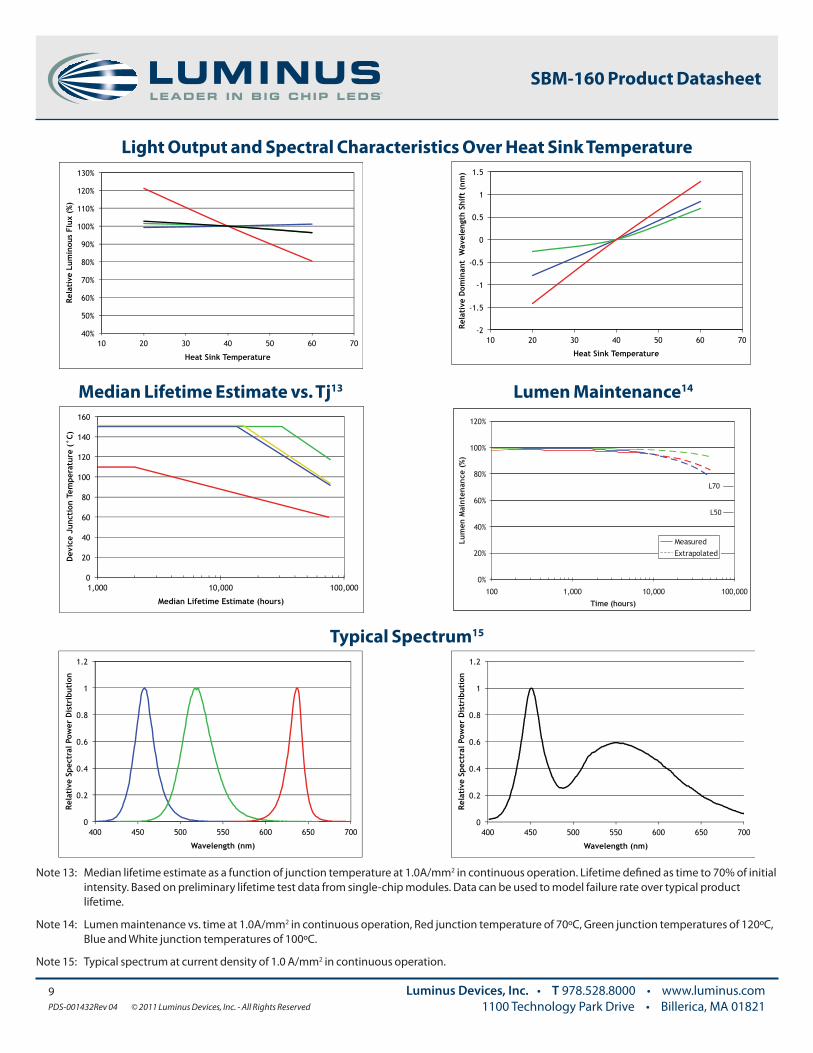
Note 13: Median lifetime estimate as a function of junction temperature at 1.0A/mm2 in continuous operation. Lifetime defined as time to 70% of initial intensity. Based on preliminary lifetime test data from single-chip modules. Data can be used to model failure rate over typical product lifetime.
Note 14: Lumen maintenance vs. time at 1.0A/mm2 in continuous operation, Red junction temperature of 70ºC, Green junction temperatures of 120ºC, Blue and White junction temperatures of 100ºC.
Note 15: Typical spectrum at current density of 1.0 A/mm2 in continuous operation.
Light Output and Spectral Characteristics Over Heat Sink Temperature
Median Lifetime Estimate vs. Tj13 Lumen Maintenance14
Typical Spectrum15
0
20
40
60
80
100
120
140
160
1,000 10,000 100,000
Dev
ice
Junc
tion
Tem
pera
ture
(°C
)
Median Lifetime Estimate (hours)
40%
50%
60%
70%
80%
90%
100%
110%
120%
130%
10 20 30 40 50 60 70
Rela
tive
Lum
inou
s Fl
ux (
%)
Heat Sink Temperature
-2
-1.5
-1
-0.5
0
0.5
1
1.5
10 20 30 40 50 60 70
Rela
tive
Dom
inan
t W
avel
engt
h Sh
ift
(nm
)
Heat Sink Temperature
0%
20%
40%
60%
80%
100%
120%
100 1,000 10,000 100,000
Time (hours)
Lum
en M
aint
enan
ce (
%)
MeasuredExtrapolated
L70
L50
0
0.2
0.4
0.6
0.8
1
1.2
400 450 500 550 600 650 700
Rela
tive
Spe
ctra
l Pow
er D
istr
ibut
ion
Wavelength (nm)
0
0.2
0.4
0.6
0.8
1
1.2
400 450 500 550 600 650 700
Rela
tive
Spe
ctra
l Pow
er D
istr
ibut
ion
Wavelength (nm)
10PDS-001432Rev 04 © 2011 Luminus Devices, Inc. - All Rights Reserved
Luminus Devices, Inc. • T 978.528.8000 • www.luminus.com1100 Technology Park Drive • Billerica, MA 01821
SBM-160 Product Datasheet
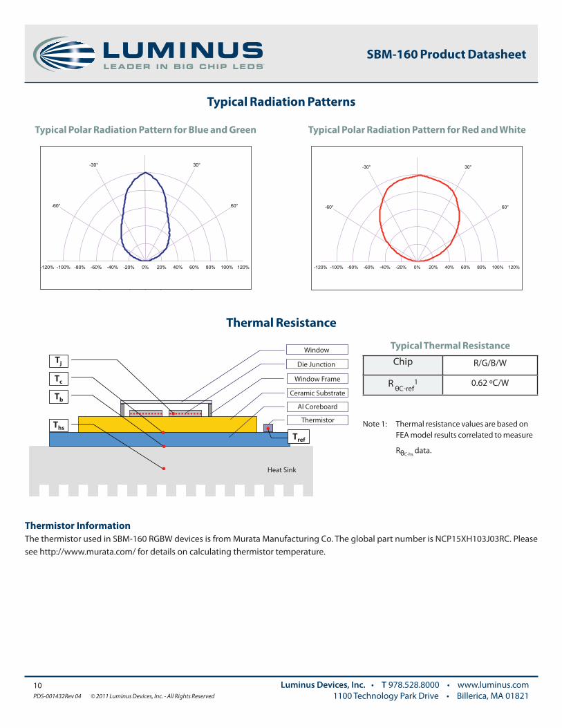
Typical Radiation Patterns
Typical Polar Radiation Pattern for Blue and Green Typical Polar Radiation Pattern for Red and White
Thermal Resistance
Typical Thermal Resistance
Chip R/G/B/W
R θC-ref1 0.62 ºC/W
Note 1: Thermal resistance values are based on FEA model results correlated to measure
RθC-hs data.
Tj
Tb
Ths
Tref
Window
Die Junction
Window Frame
Thermistor
Al Coreboard
Heat Sink
Ths de�nition = 3 mm from core-board
Tc
Ceramic Substrate
120% 100% 80% 60% 20% 40% 0% -20% -40% -60% -80% -100% -120%
30°
60° -60°
-30°
80% 100% 120% 20% 40% 60% -40% -20% 0% -100% -80% -60%
60°
30°
-120%
-30°
-60°
Thermistor Information The thermistor used in SBM-160 RGBW devices is from Murata Manufacturing Co. The global part number is NCP15XH103J03RC. Please see http://www.murata.com/ for details on calculating thermistor temperature.
11PDS-001432Rev 04 © 2011 Luminus Devices, Inc. - All Rights Reserved
Luminus Devices, Inc. • T 978.528.8000 • www.luminus.com1100 Technology Park Drive • Billerica, MA 01821
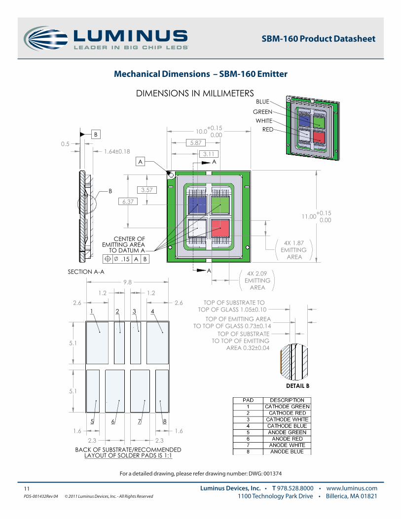
Mechanical Dimensions – SBM-160 Emitter
SBM-160 Product Datasheet
For a detailed drawing, please refer drawing number: DWG: 001374
12PDS-001432Rev 04 © 2011 Luminus Devices, Inc. - All Rights Reserved
Luminus Devices, Inc. • T 978.528.8000 • www.luminus.com1100 Technology Park Drive • Billerica, MA 01821
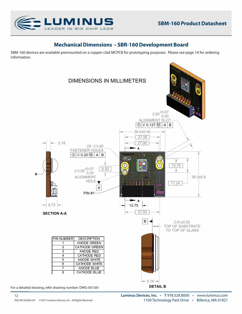
Mechanical Dimensions – SBR-160 Development Board
SBM-160 Product Datasheet
SBM-160 devices are available premounted on a copper-clad MCPCB for prototyping purposes. Please see page 14 for ordering information.
For a detailed drawing, refer drawing number: DWG-001381
0 0
Tem
pera
ture
(ºC
)
Time (sec) 30 60 90 120 150 180 210 240 270 300
25
50
75
100
125
150
175
200
225
250
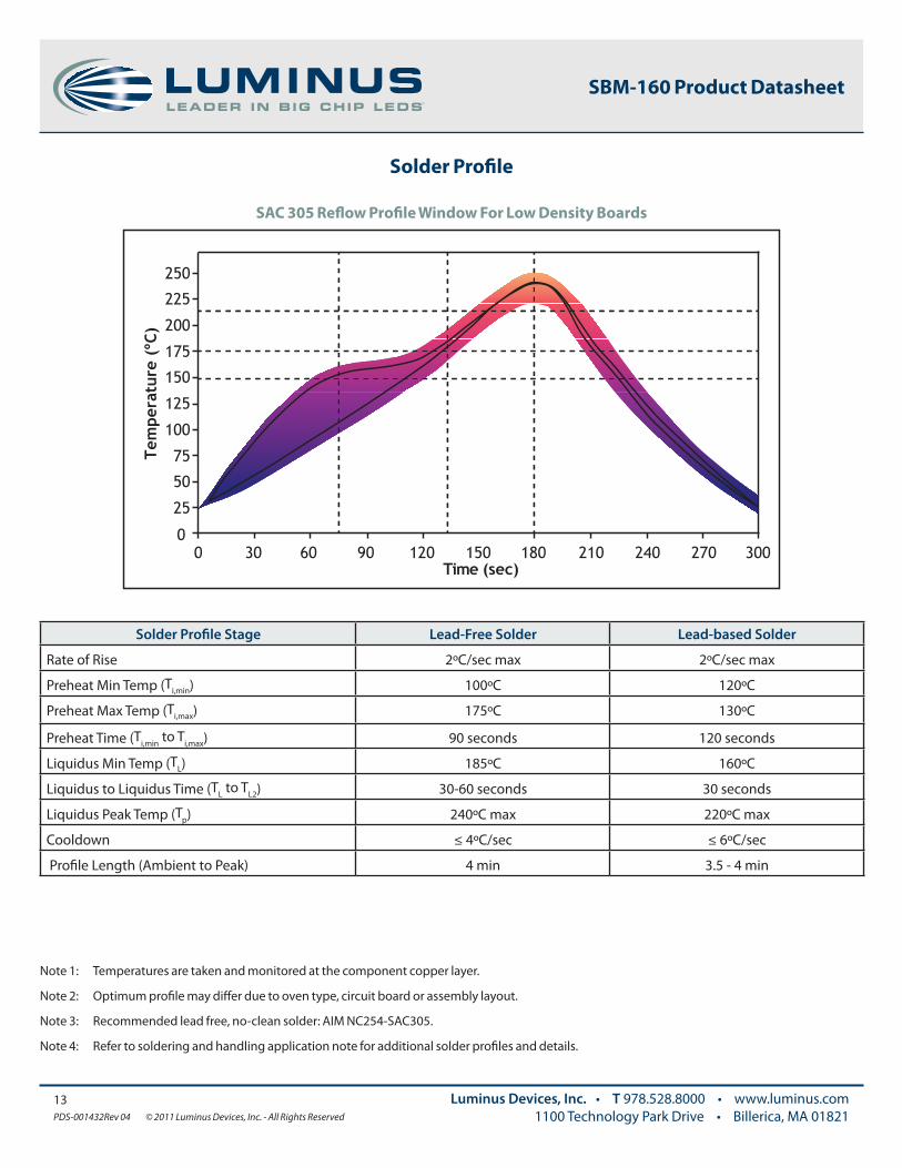
Note 1: Temperatures are taken and monitored at the component copper layer.
Note 2: Optimum profile may differ due to oven type, circuit board or assembly layout.
Note 3: Recommended lead free, no-clean solder: AIM NC254-SAC305.
Note 4: Refer to soldering and handling application note for additional solder profiles and details.
Solder Profile
13PDS-001432Rev 04 © 2011 Luminus Devices, Inc. - All Rights Reserved
Luminus Devices, Inc. • T 978.528.8000 • www.luminus.com1100 Technology Park Drive • Billerica, MA 01821
SBM-160 Product Datasheet
Solder Profile Stage Lead-Free Solder Lead-based Solder
Rate of Rise 2ºC/sec max 2ºC/sec max
Preheat Min Temp (Ti,min) 100ºC 120ºC
Preheat Max Temp (Ti,max) 175ºC 130ºC
Preheat Time (Ti,min to Ti,max) 90 seconds 120 seconds
Liquidus Min Temp (TL) 185ºC 160ºC
Liquidus to Liquidus Time (TL to TL2) 30-60 seconds 30 seconds
Liquidus Peak Temp (Tp) 240ºC max 220ºC max
Cooldown ≤ 4ºC/sec ≤ 6ºC/sec
Profile Length (Ambient to Peak) 4 min 3.5 - 4 min
SAC 305 Reflow Profile Window For Low Density Boards
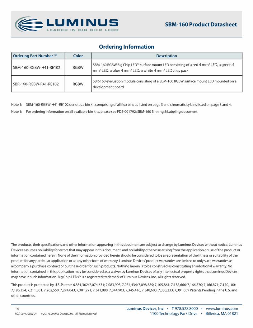
Ordering Information
The products, their specifications and other information appearing in this document are subject to change by Luminus Devices without notice. Luminus Devices assumes no liability for errors that may appear in this document, and no liability otherwise arising from the application or use of the product or information contained herein. None of the information provided herein should be considered to be a representation of the fitness or suitability of the product for any particular application or as any other form of warranty. Luminus Devices’ product warranties are limited to only such warranties as accompany a purchase contract or purchase order for such products. Nothing herein is to be construed as constituting an additional warranty. No information contained in this publication may be considered as a waiver by Luminus Devices of any intellectual property rights that Luminus Devices may have in such information. Big Chip LEDs™ is a registered trademark of Luminus Devices, Inc., all rights reserved.
This product is protected by U.S. Patents 6,831,302; 7,074,631; 7,083,993; 7,084,434; 7,098,589; 7,105,861; 7,138,666; 7,166,870; 7,166,871; 7,170,100; 7,196,354; 7,211,831; 7,262,550; 7,274,043; 7,301,271; 7,341,880; 7,344,903; 7,345,416; 7,348,603; 7,388,233; 7,391,059 Patents Pending in the U.S. and other countries.
14PDS-001432Rev 04 © 2011 Luminus Devices, Inc. - All Rights Reserved
Luminus Devices, Inc. • T 978.528.8000 • www.luminus.com1100 Technology Park Drive • Billerica, MA 01821
SBM-160 Product Datasheet
Ordering Part Number 1,2 Color Description
SBM-160-RGBW-H41-RE102 RGBWSBM-160 RGBW Big Chip LED™ surface mount LED consisting of a red 4 mm2 LED, a green 4 mm2 LED, a blue 4 mm2 LED, a white 4 mm2 LED , tray pack
SBR-160-RGBW-R41-RE102 RGBWSBR-160 evaluation module consisting of a SBM-160 RGBW surface mount LED mounted on a
development board
Note 1: SBM-160-RGBW-H41-RE102 denotes a bin kit comprising of all flux bins as listed on page 3 and chromaticity bins listed on page 3 and 4.
Note 1: For ordering information on all available bin kits, please see PDS-001792: SBM-160 Binning & Labeling document.