Embed Size (px)
Citation preview
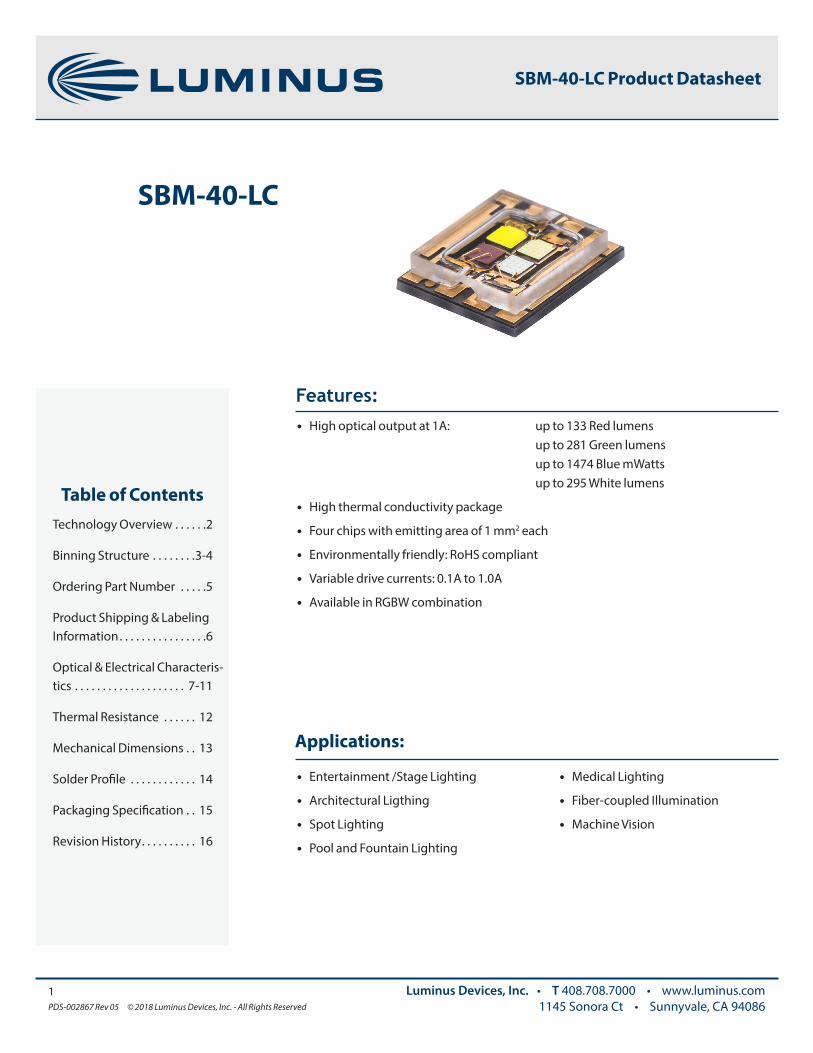
Applications:
• Entertainment /Stage Lighting
• Architectural Ligthing
• Spot Lighting
• Pool and Fountain Lighting
• Medical Lighting
• Fiber-coupled Illumination
• Machine Vision
Features:• High optical output at 1A: up to 133 Red lumens up to 281 Green lumens up to 1474 Blue mWatts up to 295 White lumens
• High thermal conductivity package
• Four chips with emitting area of 1 mm2 each
• Environmentally friendly: RoHS compliant
• Variable drive currents: 0.1A to 1.0A
• Available in RGBW combination
Table of ContentsTechnology Overview . . . . . .2
Binning Structure . . . . . . . .3-4
Ordering Part Number . . . . .5
Product Shipping & Labeling Information . . . . . . . . . . . . . . . .6
Optical & Electrical Characteris-tics . . . . . . . . . . . . . . . . . . . . 7-11
Thermal Resistance . . . . . . 12
Mechanical Dimensions . . 13
Solder Profile . . . . . . . . . . . . 14
Packaging Specification . . 15
Revision History . . . . . . . . . . 16
1PDS-002867 Rev 05 © 2018 Luminus Devices, Inc. - All Rights Reserved
Luminus Devices, Inc. • T 408.708.7000 • www.luminus.com1145 Sonora Ct • Sunnyvale, CA 94086
SBM-40-LC
SBM-40-LC Product Datasheet
Testing Temperature
Luminus surface mount LEDs are typically tested with a 20 ms input pulse and a junction temperature of 25ºC. Expected flux values in real world operation can be extrapolated based on the information contained within this product data sheet.
This method of measurement ensures that Luminus LEDs perform in the field just as they are specified.
Multiple Operating Points
The tables on the following pages provide typical optical and electrical characteristics. Since the LEDs can be operated over a wide range of drive conditions (currents from 0.1 A to 1.0A, and duty cycle from <1% to 100%), multiple drive conditions are listed.
Understanding Luminus LED Test Specifications
Every Luminus LED is fully tested to ensure that it meets the high quality standards expected from Luminus’ products.
2PDS-002867 Rev 05 © 2018 Luminus Devices, Inc. - All Rights Reserved
Luminus Devices, Inc. • T 408.708.7000 • www.luminus.com1145 Sonora Ct • Sunnyvale, CA 94086
SBM-160 Product Datasheet
Packaging Technology
Thermal management is critical in high power LED applications. With a thermal resistance from junction to case of 0.8º C/W (electrical), Luminus SBM-40-LC LEDs have industry-leading thermal resistance. This allows the LED to be driven at higher current while maintaining a low junction temperature, thereby resulting in brighter solutions and longer lifetimes.
Reliability
Designed from the ground up, Luminus LEDs are one of the most reliable light sources in the world today. Luminus LEDs have passed a rigorous suite of environmental and mechanical stress tests, including mechanical shock, vibration, temperature cycling and humidity, and have been fully qualified for use in extreme high power and high current applications. With very low failure rates and median lifetimes that typically exceed 60,000 hours, Luminus LEDs are ready for even the most demanding applications.
Environmental Benefits
Luminus LEDs help reduce power consumption and the amount of hazardous waste entering the environment. All LED products manufactured by Luminus are RoHS compliant and free of hazardous materials, including lead and mercury.
Technology Overview
Luminus LEDs benefit from a suite of innovations in the fields of chip technology, packaging and thermal management. These breakthroughs allow illumination engineers and designers to achieve solutions that are high brightness and high efficiency.
SBM-40-LC Product Datasheet

3PDS-002867 Rev 05 © 2018 Luminus Devices, Inc. - All Rights Reserved
Luminus Devices, Inc. • T 408.708.7000 • www.luminus.com1145 Sonora Ct • Sunnyvale, CA 94086
Red, Green and Blue Dominant Wavelength Bins3
SBM-40-LC Red, Green, Blue and White Binning Structure1,2,3
All SBM-40-LC LEDs are tested at 0.7A at Tambient=25ºC for luminous flux, radiometric flux and dominant wavelength and placed into one of the following wavelength and flux bins. The binning structure is universally applied across each color of the SBM-40-LC product line.
ColorMin... Max
Luminous Flux (lm) @ 0.7 A
Min...Max Radiometric Flux
(mW) @ 0.7A
Min... MaxLuminous Flux (lm)
@ 1 A(Correlated Values)
Min...Max Radiometric Flux
(mW) @ 1 A(Correlated Values)
Red 45 ... 90 60 ... 133
Green 112 ... 224 140 ... 281
Blue 630 ... 1100 844 ... 1474
White 140 ... 224 184 ... 295
Color Wavelength Bin (FF) Minumum Wavelength (nm) @ 0.7A
Maximum Wavelength (nm) @ 0.7A
Red RW 620 625
Green GW 524 529
Blue BW 452 457
SBM-40-LC Product Datasheet
Note 1: Luminus maintains a +/- 6% tolerance on flux measurements.
Note 2: Contact Luminus sales team for specific bin requirements.
Note 3: Devices are binned at standard 0.7A, 20ms pulse , Tambient=25ºC condition.
4PDS-002867 Rev 05 © 2018 Luminus Devices, Inc. - All Rights Reserved
Luminus Devices, Inc. • T 408.708.7000 • www.luminus.com1145 Sonora Ct • Sunnyvale, CA 94086
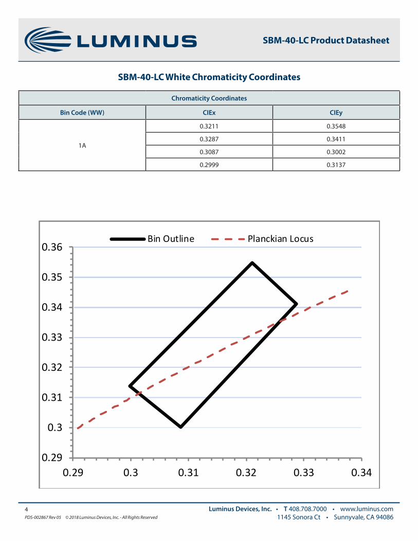
SBM-40-LC White Chromaticity Coordinates
Chromaticity Coordinates
Bin Code (WW) CIEx CIEy
1A
0.3211 0.3548
0.3287 0.3411
0.3087 0.3002
0.2999 0.3137
SBM-40-LC Product Datasheet
0.29
0.3
0.31
0.32
0.33
0.34
0.35
0.36
0.29 0.3 0.31 0.32 0.33 0.34
Bin Outline Planckian Locus
5PDS-002867 Rev 05 © 2018 Luminus Devices, Inc. - All Rights Reserved
Luminus Devices, Inc. • T 408.708.7000 • www.luminus.com1145 Sonora Ct • Sunnyvale, CA 94086
Bin KitRGB Wavelength
RGB FluxWhite Chro-
maticityWhite Flux Ordering Part Number
RW GW BW
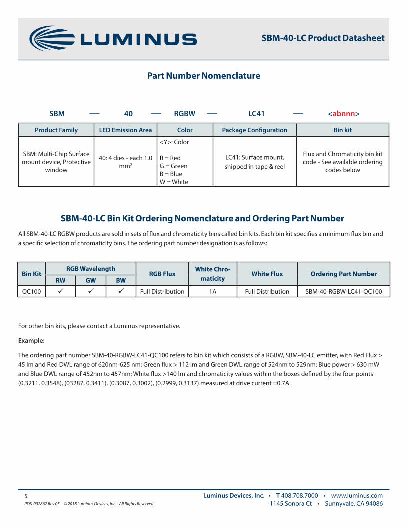
QC100 Full Distribution 1A Full Distribution SBM-40-RGBW-LC41-QC100
For other bin kits, please contact a Luminus representative.
Example:
The ordering part number SBM-40-RGBW-LC41-QC100 refers to bin kit which consists of a RGBW, SBM-40-LC emitter, with Red Flux > 45 lm and Red DWL range of 620nm-625 nm; Green flux > 112 lm and Green DWL range of 524nm to 529nm; Blue power > 630 mW and Blue DWL range of 452nm to 457nm; White flux >140 lm and chromaticity values within the boxes defined by the four points (0.3211, 0.3548), (03287, 0.3411), (0.3087, 0.3002), (0.2999, 0.3137) measured at drive current =0.7A.
SBM-40-LC Product Datasheet
Part Number Nomenclature
Product Family LED Emission Area Color Package Configuration Bin kit
SBM: Multi-Chip Surface mount device, Protective
window
40: 4 dies - each 1.0 mm2
<Y>: Color
R = RedG = GreenB = BlueW = White
LC41: Surface mount, shipped in tape & reel
Flux and Chromaticity bin kit code - See available ordering
codes below
SBM 40 RGBW LC41 <abnnn>
SBM-40-LC Bin Kit Ordering Nomenclature and Ordering Part Number
All SBM-40-LC RGBW products are sold in sets of flux and chromaticity bins called bin kits. Each bin kit specifies a minimum flux bin and a specific selection of chromaticity bins. The ordering part number designation is as follows:
6PDS-002867 Rev 05 © 2018 Luminus Devices, Inc. - All Rights Reserved
Luminus Devices, Inc. • T 408.708.7000 • www.luminus.com1145 Sonora Ct • Sunnyvale, CA 94086
SBM-40-LC Product Datasheet
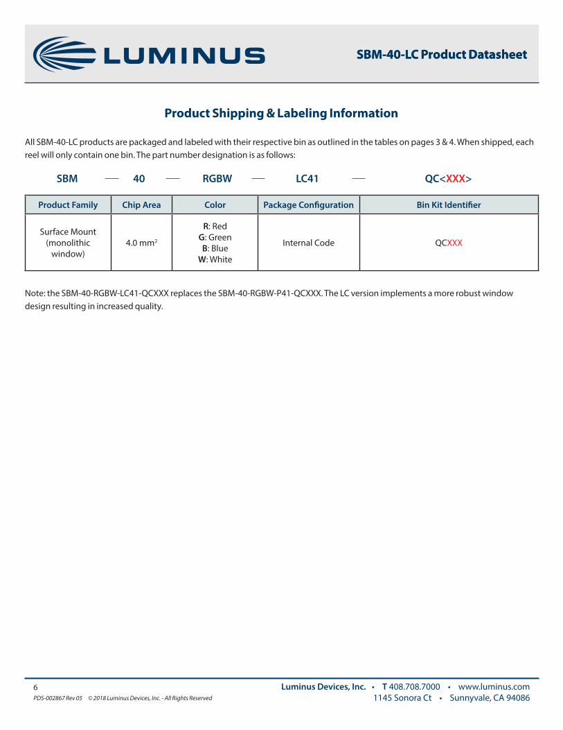
Product Family Chip Area Color Package Configuration Bin Kit Identifier
Surface Mount (monolithic
window)4.0 mm2
R: RedG: GreenB: Blue
W: White
Internal Code QCXXX
SBM 40 RGBW LC41 QC<XXX>
Product Shipping & Labeling Information
All SBM-40-LC products are packaged and labeled with their respective bin as outlined in the tables on pages 3 & 4. When shipped, each reel will only contain one bin. The part number designation is as follows:
Note: the SBM-40-RGBW-LC41-QCXXX replaces the SBM-40-RGBW-P41-QCXXX. The LC version implements a more robust window design resulting in increased quality.
SBM-40-LC Product Datasheet

7PDS-002867 Rev 05 © 2018 Luminus Devices, Inc. - All Rights Reserved
Luminus Devices, Inc. • T 408.708.7000 • www.luminus.com1145 Sonora Ct • Sunnyvale, CA 94086
SBM-40-LC Product Datasheet
Optical & Electrical Characteristics 1,2
Parameter Symbol Red Green Blue White Unit
Drive Condition3 I 0.7 0.7 0.7 0.7 A
Emitting Area - 1.0 1.0 1.0 1.0 mm2
Dominant Wavelength
λd min 620 524 452 - nm
λd typ 622 527 455 - nm
λd max 625 529 457 - nm
FWHM (typ.) Δλ1/2 17 32 21 N/A nm
Chromaticity Coordinates4 (typ.)x 0.31 -
y 0.32 -
Forward Voltage
VF min 2.0 2.8 2.8 2.8 V
VF typ 2.3 3.2 3.2 3.2 VVF max 3.0 3.6 3.6 3.6 V
Minimum Current 5 - 0.1 0.1 0.1 0.1 A
Maximum Current 5 - 1.0 1.0 1.0 1.0 A
Maximum Operating Junction Temperature 5,6
Tj operating,max 100 140 130 130 ºC
Absolute Maximum Junction Tempera-ture 5,6
Tj absolute max 115 150 150 150 ºC
Storage Temperature Range - -40/+100 -40/+100 -40/+100 -40/+100 ºC
Note 1: All ratings are based on test conditions of If = 700 mA, Tc=25ºC, 20 millisecond pulse. Tcase is defined on Thermal Resistance section, page 12.
Note 2: Unless otherwise noted, values listed are typical. Devices are production tested and specified at 0.7 A for red, green, blue and white. Values provided at 1 A based on characterization and measurements at 1 A.
Note 3: SBM-40-LC RGBW devices can be driven at currents ranging from 0.1 A to 1 A depending on color and at duty cycles ranging from 1% to 100%. Drive current and duty cycle should be adjusted as necessary to maintain the junction temperature desired to meet application lifetime requirements.
Note 4: In CIE 1931 chromaticity diagram coordinates, normalized to x+y+z=1.
Note 5: SBM-40-LC RGBW devices are designed for continuous operation to a maximum current as specified above. Product lifetime data is specified at recommended forward drive currents. Sustained operation at or beyond maximum currents will result in a reduction of device lifetime compared to recommended forward drive currents. Actual device lifetimes will also depend on junction temperature. Refer to the lifetime derating curves for further information.
Note 6: Maximum Operating Junction Temperature and Absolute Maximum Junction Temperature assume that with all four (RGBW) LEDs operating simultaneously at 1 A.

8PDS-002867 Rev 05 © 2018 Luminus Devices, Inc. - All Rights Reserved
Luminus Devices, Inc. • T 408.708.7000 • www.luminus.com1145 Sonora Ct • Sunnyvale, CA 94086
SBM-40-LC Product Datasheet
Optical & Electrical Characteristics7
Note 7: Flux and power values are measured using a current pulse of typical 20 ms. Luminus maintains a test measurement accuracy for LED flux and power of ±6%.
Relative Luminous Flux - Red Relative Luminous Flux - Green
Relative Luminous Flux vs. Ifφv/φv(0.7A) Single Pulse 20ms Tj = 25°
Relative Luminous Flux vs. Ifφv/φv(0.7A) Single Pulse 20ms Tj = 25°
Relative Luminous Flux - Blue Relative Luminous Flux - White
Relative Luminous Flux vs. Ifφv/φv(0.7A) Single Pulse 20ms Tj = 25°
Relative Luminous Flux vs. Ifφv/φv(0.7A) Single Pulse 20ms Tj = 25°
Optical & Electrical Characteristics
9PDS-002867 Rev 05 © 2018 Luminus Devices, Inc. - All Rights Reserved
Luminus Devices, Inc. • T 408.708.7000 • www.luminus.com1145 Sonora Ct • Sunnyvale, CA 94086
SBM-40-LC Product Datasheet
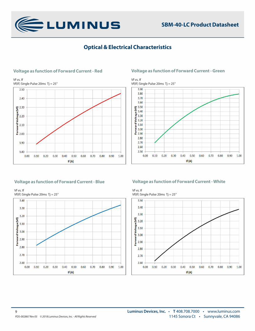
Voltage as function of Forward Current - GreenVoltage as function of Forward Current - Red
Vf vs. IfVf(If ) Single Pulse 20ms Tj = 25°
Vf vs. IfVf(If ) Single Pulse 20ms Tj = 25°
Voltage as function of Forward Current - WhiteVoltage as function of Forward Current - Blue
Vf vs. IfVf(If ) Single Pulse 20ms Tj = 25°
Vf vs. IfVf(If ) Single Pulse 20ms Tj = 25°
Optical & Electrical Characteristics
10PDS-002867 Rev 05 © 2018 Luminus Devices, Inc. - All Rights Reserved
Luminus Devices, Inc. • T 408.708.7000 • www.luminus.com1145 Sonora Ct • Sunnyvale, CA 94086
SBM-40-LC Product Datasheet
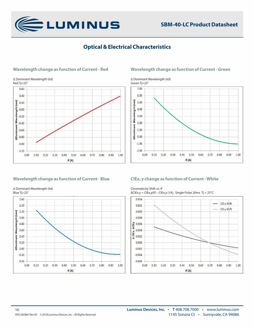
Wavelength change as function of Current - Red Wavelength change as function of Current - Green
Δ Dominant Wavelength (λd)Red Tj=25°
Δ Dominant Wavelength (λd)Green Tj=25°
Wavelength change as function of Current - Blue CIEx, y change as function of Current - White
Δ Dominant Wavelength (λd)Blue Tj=25°
Chromaticity Shift vs. IfΔCIEx,y = CIEx,y(If ) - CIEx,y (1A), Single Pulse 20ms Tj = 25°C
Optical & Electrical Characteristics
11PDS-002867 Rev 05 © 2018 Luminus Devices, Inc. - All Rights Reserved
Luminus Devices, Inc. • T 408.708.7000 • www.luminus.com1145 Sonora Ct • Sunnyvale, CA 94086
SBM-40-LC Product Datasheet
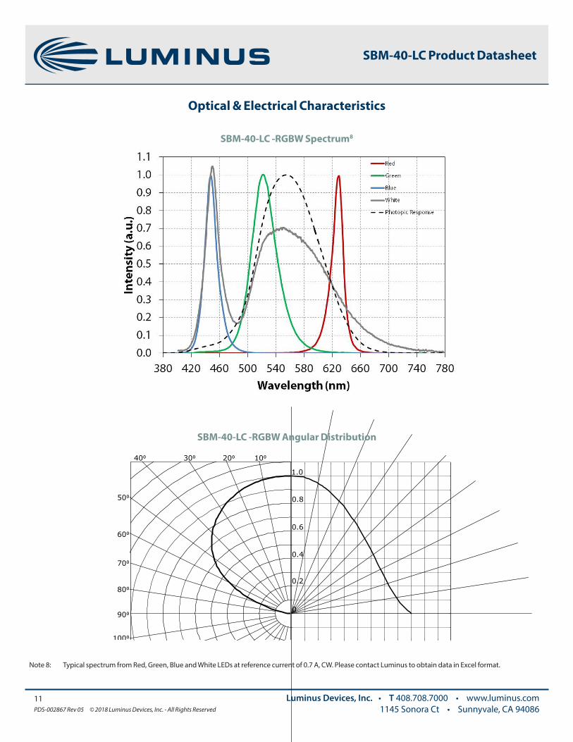
SBM-40-LC -RGBW Spectrum8
Note 8: Typical spectrum from Red, Green, Blue and White LEDs at reference current of 0.7 A, CW. Please contact Luminus to obtain data in Excel format.
50⁰
60⁰
90⁰
70⁰
80⁰
100⁰120⁰
40⁰ 30⁰ 10⁰20⁰
100⁰80⁰60⁰40⁰20⁰0⁰
0
0.6
0.2
0.4
0.8
1.0
0.6 0.40.81.0
SBM-40-LC -RGBW Angular Distribution
12PDS-002867 Rev 05 © 2018 Luminus Devices, Inc. - All Rights Reserved
Luminus Devices, Inc. • T 408.708.7000 • www.luminus.com1145 Sonora Ct • Sunnyvale, CA 94086
SBM-40-LC Product Datasheet
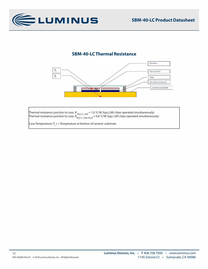
SBM-40-LC Thermal Resistance
Thermal resistance junction to case, R th(j-c)_real = 1.0 oC/W (typ.),(All chips operated simultaneously)Thermal resistance junction to case, Rth(j-c)_electrical = 0.8 oC/W (typ.) (All chips operated simultaneously)
Case Temperature (Tc ) = Temperature at bottom of ceramic substrate.
13PDS-002867 Rev 05 © 2018 Luminus Devices, Inc. - All Rights Reserved
Luminus Devices, Inc. • T 408.708.7000 • www.luminus.com1145 Sonora Ct • Sunnyvale, CA 94086
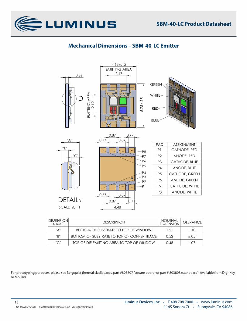
Mechanical Dimensions – SBM-40-LC Emitter
SBM-40-LC Product Datasheet
4.68 .15
5.7
5.1
5
EMITTING AREA2.17
EMITT
ING
ARE
A2.
19
0.38
D
0.77
0.87 0.87
0.77 4.48
0.77 0.87
0.87 0.77
P5P6P7P8
P4P3P2P1
"C"
"A"
"B"
DETAILD
SCALE 20 : 1
WHITE
GREEN
RED
BLUE
PAD ASSIGNMENTP1 CATHODE, REDP2 ANODE, REDP3 CATHODE, BLUEP4 ANODE, BLUEP5 CATHODE, GREENP6 ANODE, GREENP7 CATHODE, WHITEP8 ANODE, WHITE
DIMENSION NAME DESCRIPTION NOMINAL
DIMENSION TOLERANCE
"A" BOTTOM OF SUBSTRATE TO TOP OF WINDOW 1.21 .10
"B" BOTTOM OF SUBSTRATE TO TOP OF COPPER TRACE 0.52 .05
"C" TOP OF DIE EMITTING AREA TO TOP OF WINDOW 0.48 .07
For prototyping purposes, please see Bergquist thermal clad boards, part #803807 (square board) or part # 803808 (star board). Available from Digi-Key or Mouser.
0 0
Tem
pera
ture
(ºC
)
Time (sec) 30 60 90 120 150 180 210 240 270 300
25
50
75
100
125
150
175
200
225
250
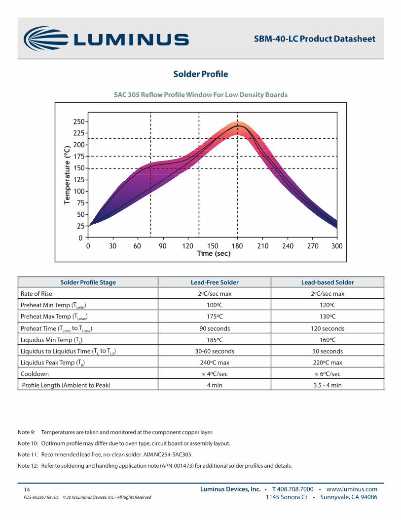
Note 9: Temperatures are taken and monitored at the component copper layer.
Note 10: Optimum profile may differ due to oven type, circuit board or assembly layout.
Note 11: Recommended lead free, no-clean solder: AIM NC254-SAC305.
Note 12: Refer to soldering and handling application note (APN-001473) for additional solder profiles and details.
Solder Profile
14PDS-002867 Rev 05 © 2018 Luminus Devices, Inc. - All Rights Reserved
Luminus Devices, Inc. • T 408.708.7000 • www.luminus.com1145 Sonora Ct • Sunnyvale, CA 94086
SBM-40-LC Product Datasheet
Solder Profile Stage Lead-Free Solder Lead-based Solder
Rate of Rise 2ºC/sec max 2ºC/sec max
Preheat Min Temp (Ti,min) 100ºC 120ºC
Preheat Max Temp (Ti,max) 175ºC 130ºC
Preheat Time (Ti,min to Ti,max) 90 seconds 120 seconds
Liquidus Min Temp (TL) 185ºC 160ºC
Liquidus to Liquidus Time (TL to TL2) 30-60 seconds 30 seconds
Liquidus Peak Temp (Tp) 240ºC max 220ºC max
Cooldown ≤ 4ºC/sec ≤ 6ºC/sec
Profile Length (Ambient to Peak) 4 min 3.5 - 4 min
SAC 305 Reflow Profile Window For Low Density Boards
15PDS-002867 Rev 05 © 2018 Luminus Devices, Inc. - All Rights Reserved
Luminus Devices, Inc. • T 408.708.7000 • www.luminus.com1145 Sonora Ct • Sunnyvale, CA 94086
SBM-40-LC Product Datasheet
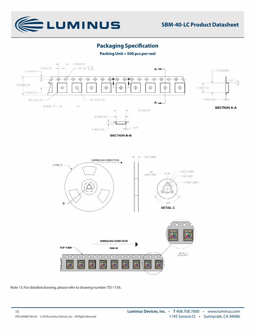
Packaging SpecificationPacking Unit = 500 pcs per reel
TOP VIEW SBM-40
178 7
C
DETAIL D SCALE 4 : 1
12.4 .488
13 .5122.00 .0793X 21.3 .839
16.0 .630
120°
DETAIL C
UNREELING DIRECTION
UNREELING DIRECTION
Note 13: For detailed drawing, please refer to drawing number: TO-1156.

The products, their specifications and other information appearing in this document are subject to change by Luminus Devices without notice. Luminus Devices assumes no liability for errors that may appear in this document, and no liability otherwise arising from the application or use of the product or information contained herein. None of the information provided herein should be considered to be a representation of the fitness or suitability of the product for any particular application or as any other form of warranty. Luminus Devices’ product warranties are limited to only such warranties as accompany a purchase contract or purchase order for such products. Nothing herein is to be construed as constituting an additional warranty. No information contained in this publication may be considered as a waiver by Luminus Devices of any intellectual property rights that Luminus Devices may have in such information.
This product is protected by U.S. Patents 6,831,302; 7,074,631; 7,083,993; 7,084,434; 7,098,589; 7,105,861; 7,138,666; 7,166,870; 7,166,871; 7,170,100; 7,196,354; 7,211,831; 7,262,550; 7,274,043; 7,301,271; 7,341,880; 7,344,903; 7,345,416; 7,348,603; 7,388,233; 7,391,059 Patents Pending in the U.S. and other countries.
16PDS-002867 Rev 05 © 2018 Luminus Devices, Inc. - All Rights Reserved
Luminus Devices, Inc. • T 408.708.7000 • www.luminus.com1145 Sonora Ct • Sunnyvale, CA 94086
Revision Date Description
Rev 01 05/08/2016 Preliminary Datasheet release
Rev 02 04/03/2017 Update binning structure and maximum current
Rev 03 04/07/2017 Refine binning structure
Rev 04 08/15/2018 Update white chromaticity bins, switch to monolithic window and change ordering part number
Rev 05 10/26/2018 Update blue maximum radiometric power to 1100mW
Revision History
SBM-40-LC Product Datasheet