Embed Size (px)
Citation preview

Sanitary Hand Power Switch This project is to build a power switch that can be turned on and off by a gentle wave of hand near the sensor. Any home appliances that can be plugged into a wall outlet can be switched on/off this way. A household extension cord is cut in half and connected to an electromechanical relay to turn on/off the appliance connected to the extension cord. A CDS photo resistor is used as the sensor. The switch is triggered by a sudden reduction and restoration of ambient light from the hand wave near the sensor. Changes that are too fast or too slow will not trigger it. This avoids an accidental trigger due to a permanent change in ambient light such as room light turned on/off or a slow change from day to night. Sensitivity and "smoothness" of the sensor can be calibrated to personal preference.
Similar switches have been seen in paper dispensers in the public bathroom and dental chair illumination lights. The purpose is to avoid physical contact with the power switch to prevent hazard or contamination from wet or dirty hands. It could be used in auto shops, baking kitchens, painting studios and chemistry laboratories.
http://youtu.be/P295x0r2GNk
Video Demonstration
Project Category: Power
WARNING: This project involves working with AC power from the wall outlet. Safety measures must be exercised. The project steps have been designed to reduce AC power hazard. Follow the construction procedure carefully. Read all instruction before construction.

Kit Overview
Circuit Schematics
Circuit Operation The basic building blocks of the electronic circuit are: 1. T-flip-flop relay on/off control. 2. Light sensor detection and trigger. 3. Power supply. T-flip-flop on/off control U1A and U1B form a cross-coupled edge-triggered T-flip-flop. They operate like two inverting logic gates with one’s output connected to the other’s input. Only two stable low/high states are possible at their outputs. R7 and R8 provide a reference voltage for the inverter inputs. D4 and D5 create an unequal voltage level of about 2V on C3 and

C4. The flip-flop is toggled by a falling edge of a positive pulse at TPB where pin 4 and pin 6 of U1 are both pulled low via C3 and C4 momentarily. Both outputs of U1A and U1B become high, creating an unstable condition where both inputs try to race to high charging capacitors C3 and C4. The one previously with the high output state will have its input held down lower (due to the unequal charge of C3 and C4) and would lose the race. This toggles the outputs until the next pulse arrives. Transistor Q1 is driven by the flip-flop to provide sufficient current to drive the relay and LED-R. D6 absorbs the energy of the relay coil to avoid flyback voltage against Q1. Light sensor The CDS photo resistor serves as a light sensor. At normal daylight condition or in a well-lit room, the resistance is about 3K – 50K Ohms. When light intensity is blocked by hand motion or any opaque object, the resistance could increase more than 50%. The photo resistor, R1, R2 and R3 form a voltage divider circuit where V1 < V2 < V3. V1D has a similar voltage level as V1 except that it is delayed by R4 and C1 for about 0.05 second. Similarly, V2D is V2 with by 5 times more delay. The difference in the voltages is detected by comparator U1C and U1D. Their outputs have open collector and connected to form a wired AND logic function with R6 as pull-up. The difference in V1, V2 and V3 are kept at about 100mV by adjusting VR1. At steady state, V1 = V1D < V2 = V2D < V3 and both outputs of U1C and U1D will be low. If there is a sudden reduction in light intensity, all three voltages V1, V2 and V3 drop immediately. Since V1D has a shorter delay than V2D, it will fall below V2D causing an input inversion at U1D and its output turns high. However, U1C output remains low and the TPA signal is still held low due to the wired AND logic function. When V2D falls to the level that is slightly higher than V1, the triggering point is reached. If the light intensity is suddenly restored, V1, V2 and V3 will rise to their original level with V2D lagging behind. At this time, U1C inputs are also inverted and the TPA signal goes high. The output goes back to low when either U1C or U1D input inversion is restored, whichever occurs first. This causes a positive going pulse at the TPA signal flipping the T-flip-flop of U1A and U1B. The three diodes D1, D2, D3 ensure that pin 8 of U1 is below VCC – 1.5V under very strong lighting condition where the photo resistor has very low resistance. This is required for the differential inputs of the comparators LM339 to operate properly. Power supply The power supply is provided by a 12VAC transformer, through a bridged rectifier DB1 and LM7812 voltage regulator for a 12VDC operation. The entire circuit only consumes

about 10mA during standby and about 70mA when the relay and LED-R is turned on. Most of the current is consumed by the relay and LEDs. The extension cord is cut in two halves and reconnected inside the project enclosure box. The fuse protects against overloading and unforeseen AC hazards.
Required tools or supplies not included Low voltage signal wires Household extension cord 2 conductor, 3 - 6 ft Adhesive and fastener to secure components, circuit board and project enclosure Soldering equipment Digital Multimeter Drill and hardware for enclosure box carpentry Two 9V battery for testing purpose Alligator clips Non-contact infrared thermometer
Est. Time Required to Complete: 6 - 12 hours

Bill of material
Name Component Quantity
Manufacturer Part Number
Jameco Part Number
CDS-Photo CDS Photo resistor 1 CDS0001-
8001 202403
D1 – D6 DIODE, General Purpose, 1N914 6 1N914 36311
DB1 DIODE BRIDGE, 1A, 50V 1 DF005M 178001
Q1 PNP, general purpose, 60V, 200mA, 2N3906 1 2N3906 38375
RELAY RELAY,12VDC@15A,SPDT, JZC-22F, 360Ohm 1 144186
T1 STEP-DOWN TRANSFORMER, 120VAC/12VAC, 200mA 1 221292
U1 IC, QUAD COMPARATOR, LM339 1 LM339 23851
IC socket, 14 pin DIP 1 37197
U2 Standard Regulator 12 Volt, 1A, 3-Pin TO-220, LM7812
1 LM7812 51334
FUSE FUSE, 5x20mm, GMA, 5A,250V 1 103932
Fuse Clips, 5mm, front leads 2 102860
ABS Plastic Enclosure, 4.9" x 2.5" x 1.5" 1 18914
PROTOBOARD, 4.1 x 2.4 inch 1 28178
LED-R LED, Uni-Color, Red, 5mm 1 333973
LED-G LED, Uni-Color, Green, 5mm 1 334086
VR1 Resistor, Trimmer, 10K 1 182837 R1, R2, R14, R16 RESISTOR, 10K, 0.25W 4 691104
R3, R6 RESISTOR, 47K, 0.25W 2 691260 R4, R7, R8, R10, R11
RESISTOR, 100K, 0.25W 5 691340
R5, R9, R12 RESISTOR, 470K, 0.25W 3 691500
R13 RESISTOR, 4.7K, 0.25W 1 691024

R15, R17 RESISTOR, 2K, 0.25W 2 690937
C1, C2 CAPACITOR, POLARIZED, 0.47uF, 50V 2 330465
C3, C4 CAPACITOR, Ceramic, 0.022uF, 50V 2 15245
C5 CAPACITOR, POLARIZED, 1000uF, 25V 1 93833
C6 CAPACITOR, POLARIZED, 100uF, 25V 1 93761

Component pin identification
Component Pin Identification Schematic representation
CDS Photo resistor
D1 - D6, 1N914, Diode
DB1, DF005M, Diode Bridge
Q1, 2N3906
RELAY

T1, Transformer, 120VAC, 12VAC
U1, LM339
U2, LM7812
FUSE
VR1, Trimmer resistor
VI GND VO

LED-R, LED-G, LED, Red or Green color
C3, C4, Capacitor
C1, C2, C5, C6, Electrolytic Capacitor
R1 – R17, Resistor, 0.25W

Resistor color codes (5% error tolerance)
Name Value Resistor color code R1, R2, R14, R16 10K Brown-Black-Orange-Gold R3, R6 47K Yellow-Purple-Orange-Gold R4, R7, R8, R10, R11 100K Brown-Black-Yellow-Gold R5, R9, R12 470K Yellow-Black-Yellow-Gold R13 4.7K Yellow-Black-Red-Gold R15, R17 2K Red-Black-Red-Gold

Project Steps Step 1: Light sensor module construction Objective: Construct and test the light sensor module
The surface of CDS photo resistor opposite the pin leads is light sensitive. The photo resistor should be enclosed in an opaque non-reflective tube to reduce the sight angle of the sensor. This is the angle where ambient light can reach the sensor as shown in the following figure. Any opaque material with non-reflective inner wall is acceptable. The plastic tube of a ballpoint pen cut to a proper length seems to serve well. The tube decreases the sight angle of the sensor. This improves the sensitivity because when your palm (or any opaque masking object) is placed near the tube opening, almost all light are blocked creating a larger difference in resistance change for detection. However, increasing the tube length also reduces the amount of light hitting the sensor and requires a stronger ambient light intensity to produce sufficient difference in resistance. A length of 1 – 3 times the diameter of the photo resistor works well in practice. A permanent light source such as an LED can be used to illuminate the sensor if the ambient room light is extremely low. The circuit could work in very faint lighting condition but could not work in total darkness. Two low voltage signal wires connect the photo resistor to the main unit. Any flexible wires will serve well. Wires taken from broken computer mouse, earphone or telephone
Sight Angle
Opaque Tube
Light sensor
Detected Light
Masking object
Blocked Light

are good choices. Shorting the wires will not cause harm to the electronic circuit. The opaque tube also needs to be mechanically secured so that it can be attached to the desired locations. Use clips, hooks, etc. Test 1A: Light sensor resistance With the mechanical construction completed, use a Digital Multi Meter (DMM) to measure the resistance between the two terminals of the photo resistor without it connected to anything else. Use your hand to block the light at the desired trigger location, about one inch from the tube opening. If the measured resistance is between 3K to 50K Ohms with the sensor exposed and at least 30% increased resistance with sensor blocked, the construction is acceptable. Repeat the test on different ambient lighting conditions where the power switch will be used, for example, day/night time with/without room light. The circuit has adjustment VR1 to adjust the sensitivity of the sensor. Too much sensitivity is not desired as it is susceptible to a false trigger such as a person walking by near the sensor. The desired range of the sensor is typically a 1 - 2 inches from the tube.
Test 1A: Measuring light sensor resistance.

Step 2: Component placement on circuit board Objective: Place circuit board components to ensure feasibility This is a component planning step without soldering. Insert all components on the circuit board. The recommended component placement is given below. Some components may have a slightly different size than the placement plan given and it may not be possible (nor necessary) to have identical placement. Cut or trim your circuit board to fit the project enclosure space in this step. It is important to place all components before soldering to avoid time consuming rework after soldering. Use Scotch Tape to secure IC sockets and components to the circuit board if necessary. Some soldering points are needed on the top side of the circuit board to connect the wires from the photo resistor and AC power lines. Make sure that these soldering points have sufficient clearance from other components for easy soldering access. Components leads of resistors or capacitors are ideal for making these soldering points. In the suggested plan shown below, LED-R, LED-G are positioned to avoid off-board wires. Do not drill holes on the enclosure board in this step. Wait till Test 4L has been completed. You may need to reposition them due to wiring errors. Some components, notably the relay, may not have standard pin configurations and you may need to drill additional holes on the circuit board to place them. Note that the bottom-view is left-right flipped.

The AC power lines of the extension cord will be connected to the relay to be switched on/off. Make sure that the relay pins are correctly identified using resistance measurement of your Digital Multimeter (DMM). The coil resistance should be about 200 - 300 Ohms. If the relay is not SPST type, it will have more than two switch contact pins. Make sure you identified them correctly. Energize the relay coil with 12V DC battery power and measure the switch resistance to identify the pins. The datasheet of the component may contain errors. Do not solely rely on the data sheet information to avoid AC power line hazard.
WARNING: Relay will be connected to AC power lines. Verify the pin configuration with your DMM. Do not solely rely on the datasheet information to
avoid AC power hazard. Datasheet may contain errors or may be outdated.

Step 3: Circuit board wiring Objective: Solder circuit board components and wires After the previous step, we have established the component placement and how everything is to be fitted into the project enclosure box. We are now ready to solder the components on the circuit board according to the wiring diagram. It is recommended to start with the signal wiring before VCC and GND wiring. The excess component leads can be used for the front side soldering points. The board is divided into HOT and COLD sections to identify the high voltage areas. Leave more room for the soldering points of extension cord because the wires are thicker. You can drill holes on the circuit board and use nuts and bolts for electrical connection. This method requires more board space allocation. Do not install the transformer T1 in this step. The transformer wiring will be done in a later step. However all wiring involving the transformer, relay and extension cord need to be marked and reserved. The two wires to the photo resistor need to be soldered in this step for testing. They will be de-soldered later to fit the wire inside the enclosure box.
Component soldering completed at Step 3.

Wiring on back side of the circuit board
Caution: Use the wiring plan as the reference. Do not use the prototype photos. The board and components provided may be different.
Step 4: Electronic circuit operation tests Objective: Test the operation of the electronic circuit with battery power. Prior to this step, all low-voltage wiring of the circuit has been completed. For safety reason, most of the testing will be done with battery power. After the electronic circuit and AC power supply are tested and verified, they will be connected together at a later step. Completion of mechanical construction is not necessary at this step. Make sure that you follow the test procedures below in the order described. This is essential to ensure that you have wired the components properly. It also minimizes the risk of permanently destroying ICs due to improper construction, soldering or defective components. When installing IC to its socket, pay attention to the polarity. Wrong installation may cause permanent damage to the IC. Use the continuity test of DMM to check wiring and soldering when in doubt. Test 4A: Component polarity The following components are polarized. Check to make sure that they have been wired properly: LED-R, LED-G, DB1, D1 – D6, C1, C2, C5, C6, Q1, U1, U2, T1. Test 4B: GND network continuity
The purpose this test is to make sure that the soldering work of the GND network is good. This is done without U1 in the socket and no power supply to the circuit. Set your Digital Multimeter (DMM) to beeping continuity test or resistance measurement. Pick a component of the GND line, for example the negative pin of C1. Measure the continuity to every test-point listed below to ensure that the resistance is less than a few Ohms.
WARNING: Follow the test procedures in the order described. Do not proceed to the next test until the current test has passed.

Test 4B: Test-points for GND network continuity test. No power should be applied. U1 pin 12 U2 pin GND (center) D6 pin A DB1 negative pin LED-R pin K R3, R8, C1, C2, C5, C6 RELAY
Test 4C: VCC network continuity
This test is the same as Test 4B but repeated for the VCC network. The following test points must be connected:
Test 4C: Test-points for VCC network continuity test. No power should be applied. U1 pin 3 U2 pin VO D1 pin A Q1 pin E LED-G pin A R6, R7, R13, R14, C6
Test 4D: IC pin short-circuit to VCC or GND This test ensures that no signal pin of U1 is shorted to the VCC or the GND network. Do not install U1. Do not apply any power to the circuit during this test. Set your DMM to beeping continuity test or resistance measurement. Measure the resistance of every pin at the IC socket to the GND line. The resistance should not be near zero, except for pin 12. Otherwise you have a short circuit at the pin. Repeat the same test for short-circuit to the VCC power network. The resistance should not be near zero, except for pin 3.

Test 4E: VCC to GND resistance In this test, we want to make sure that there is no short-circuit in the power supply network. Do not install U1. Do not apply any power. Use a DMM to measure the resistance between pin 3 and pin 12 of U1 socket. It should be more than 1K Ohms. The resistance is primarily from the internal resistance of LM7812. If this resistance is below several Ohms, you definitely have a VCC to GND short circuit. Check your soldering work to locate the problem. Do not power up the circuit when there is VCC to GND short. Due to the large capacitance of C6, the resistance measurement might need half a minute to settle to the final resistance reading depending on the DMM. Test 4F: Current consumption, AC to DC rectifier and voltage regulation If all the above tests passed, you are ready to apply battery power. Use small, low power batteries such as AA sized. Do not use lead-acid battery or any type that can supply high current. The circuit will only draw at most 70mA during normal operation and testing. Do not install U1. Connect 16 – 18VDC battery power (two small 9V batteries connected in series is acceptable) between the two AC pins of DB1. These are the two pins that are currently unconnected to T1. Measure the current consumption drawn at the battery. It should be no more than 10mA. If the current consumption is significantly higher, remove the power immediately and check for short-circuit, improper soldering, incorrect component values or defective components. The most likely cause is incorrect polarity of DB1, U2. If the current consumption is safe, check the following voltages:
1. The positive and negative pins of DB1 should be 1.0 – 1.4V less than the battery voltage due to the forward bias voltage of its internal bridged diodes.
2. The OUT and COM pins of LM7812 should be a steady voltage in the range of 11.5 – 12.5V. The IN pin of LM7812 should be 2V more than the OUT pin for LM7812 to operate properly. Check LM7812 polarity if the voltages are not correct.
Both LED-G and LED-R should be off when power is applied because U1 is not installed. If LED-G is on, check for short circuit of R15 or the IC socket. If LED-R is on, check Q1 polarity and R7 wiring. Now, change the battery polarity so that voltage applied to the two AC pins of DB1 is reversed. The measured current should be the same (within +/- 0.5mA). All voltages measured above should also be observed. This verifies the AC to DC rectifying capability of DB1. Check the polarity of DB1 if this test fails.

Test 4F: Measuring current consumption. Test 4G: IC socket voltage levels Do not install U1. Connect 16 – 18VDC battery power between the two AC pins of DB1. Measure the voltages of the pins of U1 socket with respect to GND:
Test 4G: Voltage levels of IC socket with respect to GND. U1 not installed.
Test point Voltage
pin 3 pins 4, 6 pins 5, 7 pin 8 pins 9, 10 pin 11 pin 12
12.0V 12.0V 6.0V 1 .0 – 10.0V depending on sensor Lower than pin 8 Lower than pin 9 0V
The 12.0V at pin 3 is the VCC power supply from the voltage regulator U2 (LM7812). With U1 unconnected, pins 4 and 6 pulled high by R14 and R13 and should measure 12.0V. The pins 5, 7 voltage is from the divider of R7 and R8. If the voltage level is not correct, check the resistor values. Pins 8 reading depends on the photo resistor. Under very bright light, its resistance could be as low as 3K Ohms giving a voltage near 10.0V. In very dark lighting condition, the resistance could be as high as 500K Ohms giving a voltage near 1.0V. The pins 9, 10 voltage is the result of the voltage divider of R1 and R2 and therefore should be lower than that measured at pin 8. Pins 11 voltage is the result of the voltage divider of R2 and R3 and therefore should be lower than that measured at pin 9. Pin 12 is connected to GND and should be 0V.
Test 4H: LED-G operation Apply the 16 – 18VDC battery power between the two AC pins of DB1. Measure the current consumption of the battery while performing this test. The current consumed should be the same as Test 4F (less than 10mA) since this is the same setup. Use a pin lead to short pin 2 of U1 socket to GND (pin 12) momentarily (less than 0.5 second). LED-G should turn on with normal brightness when the pin is shorted to GND. An additional 5 – 6mA of current is drawn from the battery. If LED-G does not turn on or excessive current is consumed, check its polarity and the value of R15 and R13.
Caution: Do not install U1 into socket until Tests 4A – 4G have all passed. Doing so may cause IC damages. Check your soldering work if any test fails.

Test 4H: Shorting pin 2 to GND with a scrap pin lead to test LED-G. Test 4I: Relay and LED-R operation Apply the 16 – 18VDC battery power between the two AC pins of DB1. Measure the current consumption of the battery while performing this test. The current consumed should be the same as Test 4F (less than 10mA) since this is the same setup. Use a pin lead to short pin 1 of U1 socket to GND (pin 12) momentarily (less than 0.5 second). LED-R and the relay should both turn on when he pin is shorted to GND. You should be able to hear the relay click when it turns on/off. An additional 45 – 65mA of current should be consumed when they turn on. If LED-R and the relay both do not turn on and no current is consumed, check the polarity of Q1, the values of R14 and R16. If excessive current (more than 65mA) is consumed, remove pin 1 from GND immediately as the large current could cause permanent damage to the component that is consuming excessive current. Remove D6, R14, RELAY, LED-R, R17, and R16 in this order to see which component is consuming excessive current. The most likely cause is wrong polarity of D6.
Pin lead

If the relay is on but LED-R cannot turn on, check the LED polarity and the value of R17. Do not proceed with further test if this test fails due to excessive current when pin 1 or pin 2 is shorted to GND. Doing so can cause damage to the component that is consuming excessive current. If the current measured is within limit, you can leave pin 1 shorted to GND and observed it for several minutes to see if all the components can sustain the operations and maintain the current consumption within the limit. Test 4J: T-flip-flop operation It is important to pass Tests 4H and 4I before installing U1 to start this test. The connection at TPA and TPB should also be broken to conduct the T-flip-flop switching test. Remove battery power and install U1. Reapply power and observe the current consumption from the battery. The current consumption should be less than 20mA with the relay off. With the relay on, an additional 45 – 65mA is drawn by the relay and LED-R. Remove the power immediately if the current consumption is out of range (more than 85mA). LM339 may be installed incorrectly or defective. Either LED-R or LED-G should be on. If you observe that both LEDs are on or both are off simultaneously, the flop-flop has failed. Check the wiring of the inputs R10, R11 and the polarity of D4 and D5. Also measure the voltage levels of the input and output pins of U1A and U1B to find the cause. We now verify the flipping operation of the T-flip-flop. Make sure that the connection at TPA and TPB is broken so that the outputs of U1C and U1D are isolated from the flip-flop. Use an alligator clips to connect a 47K resistor from TPB to VCC. This replaces R6 that was disconnected due to the broken connection. Use another alligator clip and shorts TPB to GND and remove it quickly (less than 0.5 second). This simulates a pulse at TPB. You should see that the flip-flop changes state switching the relay and LED-R on/off. If this operation fails check the components of the flip-flop, C3, C4, R7 through R14.
WARNING: Do not proceed with further test if Test 4H or 4I fails due to excessive current. Doing so can cause damage to the component that is consuming excessive current.
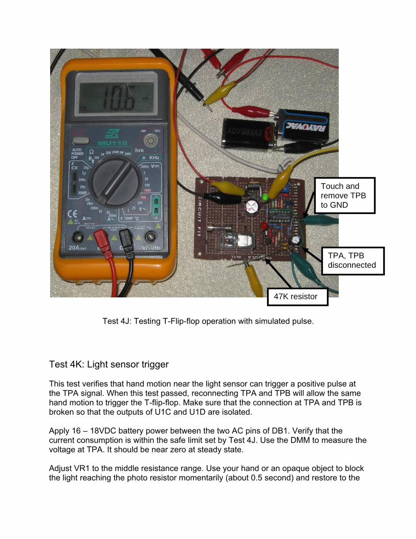
Test 4J: Testing T-Flip-flop operation with simulated pulse. Test 4K: Light sensor trigger This test verifies that hand motion near the light sensor can trigger a positive pulse at the TPA signal. When this test passed, reconnecting TPA and TPB will allow the same hand motion to trigger the T-flip-flop. Make sure that the connection at TPA and TPB is broken so that the outputs of U1C and U1D are isolated. Apply 16 – 18VDC battery power between the two AC pins of DB1. Verify that the current consumption is within the safe limit set by Test 4J. Use the DMM to measure the voltage at TPA. It should be near zero at steady state. Adjust VR1 to the middle resistance range. Use your hand or an opaque object to block the light reaching the photo resistor momentarily (about 0.5 second) and restore to the
47K resistor
TPA, TPB disconnected
Touch and remove TPB to GND
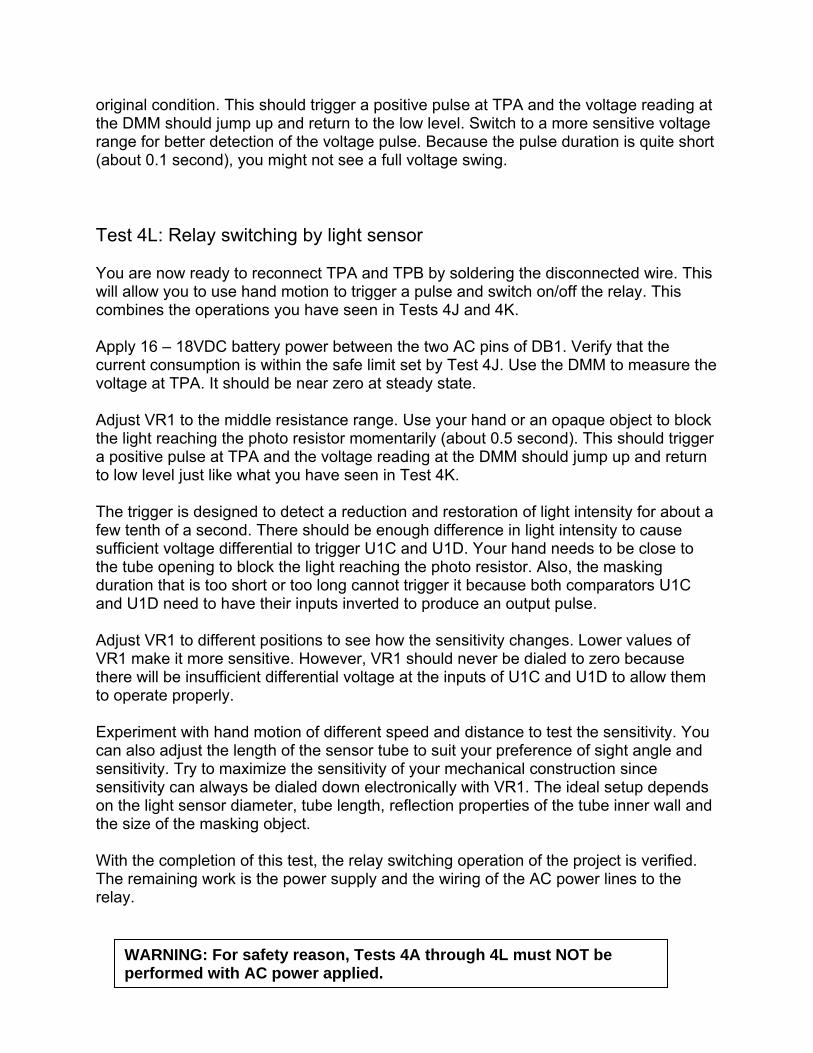
original condition. This should trigger a positive pulse at TPA and the voltage reading at the DMM should jump up and return to the low level. Switch to a more sensitive voltage range for better detection of the voltage pulse. Because the pulse duration is quite short (about 0.1 second), you might not see a full voltage swing. Test 4L: Relay switching by light sensor You are now ready to reconnect TPA and TPB by soldering the disconnected wire. This will allow you to use hand motion to trigger a pulse and switch on/off the relay. This combines the operations you have seen in Tests 4J and 4K. Apply 16 – 18VDC battery power between the two AC pins of DB1. Verify that the current consumption is within the safe limit set by Test 4J. Use the DMM to measure the voltage at TPA. It should be near zero at steady state. Adjust VR1 to the middle resistance range. Use your hand or an opaque object to block the light reaching the photo resistor momentarily (about 0.5 second). This should trigger a positive pulse at TPA and the voltage reading at the DMM should jump up and return to low level just like what you have seen in Test 4K. The trigger is designed to detect a reduction and restoration of light intensity for about a few tenth of a second. There should be enough difference in light intensity to cause sufficient voltage differential to trigger U1C and U1D. Your hand needs to be close to the tube opening to block the light reaching the photo resistor. Also, the masking duration that is too short or too long cannot trigger it because both comparators U1C and U1D need to have their inputs inverted to produce an output pulse. Adjust VR1 to different positions to see how the sensitivity changes. Lower values of VR1 make it more sensitive. However, VR1 should never be dialed to zero because there will be insufficient differential voltage at the inputs of U1C and U1D to allow them to operate properly. Experiment with hand motion of different speed and distance to test the sensitivity. You can also adjust the length of the sensor tube to suit your preference of sight angle and sensitivity. Try to maximize the sensitivity of your mechanical construction since sensitivity can always be dialed down electronically with VR1. The ideal setup depends on the light sensor diameter, tube length, reflection properties of the tube inner wall and the size of the masking object. With the completion of this test, the relay switching operation of the project is verified. The remaining work is the power supply and the wiring of the AC power lines to the relay.
WARNING: For safety reason, Tests 4A through 4L must NOT be performed with AC power applied.

Step 5: AC relay switching construction and testing Objective: Construct and test relay’s AC switching Cut a household extension cord in half and solder the male and female sides of the extension cord to the circuit board based on the wiring plan given in Step 2. For North America US, the pin polarity of the AC power outlet is shown below. Check your local electrical code for other parts of the world.
North America US AC power outlet pin polarity.

Test 5A: Relay switched off isolation With T1 still unconnected, apply 16 – 18VDC battery power between the two AC pins of DB1. Do not apply AC power in this test. Set your DMM to resistance measurement higher than 10M Ohm range. Operate the switch so that the relay is off (LED-R off). Measure the resistance between the HOT line of the male and the HOT line of female of the extension cord. The resistance should exceed 10M Ohm. If not, you might have a wrong wiring or a defective relay. Also measure the resistance from HOT to NEUTRAL at the female side of extension cord with the relay off. Again, the resistance should exceed 10M Ohm to pass this test.
Test 5A and 5B: Measuring extension cord isolation and contact resistance Test 5B: Relay switched on resistance Apply 16 – 18VDC battery power between the two AC pins of DB1. Do not apply AC power in this test. Turn on the relay (LED-R on). Set your DMM to the lowest resistance range. Measure the resistance between the HOT line of the male side and the HOT line of the female side of the extension cord. It should be near zero Ohm. Also measure the NEUTRAL lines of the male and female sides of the extension cord. It should be near zero Ohm regardless of whether the relay is on or off. If any of the measured resistances exceeds 1 Ohm, check your soldering work or extension cord.

If this test fails, trace the conduction path to locate the high resistance point. It could come from the extension cord plug or socket, relay, soldering points or the fuse. Do not use the extension cord or the high resistance will generate excessive heat, a fire hazard.
WARNING: For safety reason, Test 5A and 5B must be done WITHOUT
any AC power.

Step 6: AC power supply construction and testing Objective: Construct and test AC power supply Prior to this step, we have verified the operation of the electronic circuit with battery power. Now you are ready to solder the primary (high voltage) side of the transformer T1. The male side of the extension cord also needs to be soldered to provide AC power. Do not connect the female side to any AC appliances. Before soldering, measure the resistance of the transformer’s primary and secondary. The primary should have higher resistance than he secondary. Leave the low voltage side of the transformer unconnected first. It will be connected after Test 6A has passed. Safety precautions when measuring wall outlet AC voltage: 1. Use alligator clips to secure the DMM probes to test points before plugging into the
AC wall outlet. 2. Unplug AC power immediately after the measurement is taken. Do not handle the
circuit board, DMM or probes when AC power is active. 3. Do not probe the circuit when AC power is active. Probing action might cause short-
circuit accidentally. 4. Beware that the HOT section of the circuit board carries live AC voltage. Avoid any
human body contact. Test 6A: Transformer secondary AC voltage Plug in the male side of the extension cord to energize the transformer. Measure the AC voltage at the secondary of the transformer (the open terminals to be connected to DB1). It should be 13 – 16VAC. If the voltage is very high, you might have the primary and the secondary reversed. If no AC voltage is measured, check the fuse and primary side connection of the transformer to see if 120VAC is reaching the primary. Test 6B: AC power supply With Test 6A passed, disconnect AC power and solder the transformer secondary to the two AC pins of DB1. Plug in the male side of the extension cord to energize the transformer. Measure the AC voltage at the secondary of the transformer. The voltage should be 12 – 16VAC, slightly lower than the voltage measured in Test 6A when the transformer secondary was unconnected. If the AC voltage at the transformer secondary is normal, set your DMM to DC voltage

and measure the voltage across C5. It should be 15 – 20VDC. If this voltage is near 12V, C5 could be defective. Next measure the voltage between VCC and GND. This is the voltage across C6. It should be 11.5 - 12.5V. This verifies that U2 is regulating the voltage properly. Note that LM7812 is a linear voltage regulator. The input voltage needs to be higher than the output for proper voltage regulation. This “drop out” voltage is typically 2.0V at 1A current consumption. The electronic circuit consumes less than 85mA. So, the drop out voltage should be less, perhaps 1.0 – 1.5V depending on the manufacturer. If the VCC voltage is very low and/or the AC voltage is also low, there could be a short-circuit overload of the VCC and GND. LM7812 has self protection against this condition. Nevertheless, the power should be immediately removed to avoid device overheat. Repeat the tests starting from Test 4A to locate the problem area.
WARNING: For safety reason, do not handle the test probes, circuit board or change the DMM measurement range while AC power is active.

Step 7: System completion Objective: Final construction and system test At this step, many critical tests have been conducted. You are now ready to install the circuit board into the project enclosure box. Drill holes to show LED-R and LED-G. Also drill holes for extension cord and light sensor wires. To prevent external force on the extension cord from ripping the internal soldering, make a kink or a knot at the location where a cord enters the enclosure box. This is an important mechanical construction to prevent AC power hazard. If the internal soldering of the extension cord is loose, AC power line short-circuit may occur.
Kinks inside the enclosure box avoid ripping extension cord soldering joints.
Wire kinks to avoid ripping

Test 7A: Operating temperature First test the entire system with only the male side of the extension cord plugged in. The female side is unconnected to any AC appliance. Use a non-contact infrared thermometer to measure the temperature everywhere on the circuit board. The temperature should be no more than 10 degree C above ambient temperature. T1 is probably the device that generates the most heat. Measure other devices on the circuit board for excessive temperature. You may need to let the unit operate for more than 10 minutes to reach the equilibrium temperature.
Test 7A: Measuring temperature with a noncontact infrared thermometer. Test 7B: AC appliances switching This is the first test that draws current from the female side of the extension cord. Start with a low power AC appliance such as a night light or a low power radio (less than 10W). Plug in the AC appliance into the female side of the extension cord and check that the AC appliance can be turned on/off properly by the relay. If this test passed, you can now plug in the actual device you want to operate. The internal fuse is rated at 5A capable of supplying 600W at 120V line voltage. It protects against overloading the relay switch and extension cord. For safe operation, do not exceed 500W load.

Continue to monitor the unit’s temperature when in operation, especially under heavy AC load. Weak solder joints, defective extension cord or relay can still operate but might generate excessive heat. The extension cord temperature should be no more than 2 degrees C above ambient under any circumstance. With the conclusion of this test, you have completed the project.
Completed project.

Summary of test procedures
Test procedures
Passing criteria
Test 1A: Resistance of photo resistor with its mechanical construction.
3K to 50K Ohms with the sensor exposed and at least 30% resistance increase with the sensor blocked.
Test 4A: Component polarity.
LED-R, LED-G, DB1, D1 – D6, C1, C2, C5, C6, Q1, U1, U2, T1 wired with the correct polarity.
Test 4B: Continuity test of GND network. No power supply.
The following component pins have near zero resistance among them: U1 pin 12 U2 pin GND (center) D6 pin A DB1 negative pin LED-R pin K R3, R8, C1, C2, C5, C6 RELAY
Test 4C: Continuity test of VCC network. No power supply.
The following component pins have near zero resistance among them: U1 pin 3 U2 pin VO D1 pin A Q1 pin E LED-G pin A R6, R7, R13, R14, C6
Test 4D: IC output pins shorted to VCC or GND. U1 not installed. No power supply.
No signal pin of U1 socket is shorted to the GND network. No signal pin of U1 socket is shorted to the VCC network.
Test 4E: VCC to GND resistance. U1 not installed. No power supply.
Measured resistance more than 1K Ohms between VCC and GND (U1 pin 3 and pin 12).
Test 4F: Current consumption and AC to DC rectifier. U1 not installed. Battery power supply only.
Measured current drawn from battery is no more than 10mA. Measured current is within +/- 0.5mA when battery voltage polarity at AC pins of DB1 is reversed.

Measured voltage between OUT and COM pins of LM7812 is 11.5 – 12.5V. LED-G and LED-R are both off.
Test 4G: U1 socket voltage. U1 not installed. Battery power supply only.
Measured voltage at U1 socket pins: Pin 3 = 12.0V Pins 4, 6 = 12.0V Pins 5, 7 = 6.0V Pin 8 = 1.0 – 10.0V depending on sensor Pins 9, 10 = Lower than pin 8 Pin 11 = Lower than pin 9 Pin 12 = 0V
Test 4H: Current consumption of LED-G. Battery power supply only.
Measured current is no more than 6mA above current measured in Test 4F when LED-G turns on.
Test 4I: Current consumption of RELAY and LED-R. Battery power supply only.
Measured current is no more than 65mA above current measured in Test 4F when relay is on.
Test 4J: T-flip-flop operations. Battery power supply only.
Measured current is no more than 20mA when relay is off. Measured current is no more than 85mA when relay is on. T-flip-flop can toggle on/off when TPB is shorted to GND.
Test 4K: Light sensor trigger pulse. Battery power supply only.
Positive pulse measured at TPA when light sensor trigger condition is met.
Test 4L: Combined operation of light sensor and T-flip-flop. Battery power supply only.
Light sensor can trigger relay on/off. Light sensor masking duration that is too short or too long cannot trigger relay switching. VR1 can adjust the sensitivity of the trigger.
Test 5A: Relay switched off isolation. Battery power supply only.
Measured resistance is more than 10M Ohms between male HOT and female HOT lines of extension cord when relay is off (LED-R off). Measured resistance is more than 10M Ohm between female HOT and female NEUTRAL lines of extension

cord when relay is off.
Test 5B: Relay switched on contact resistance. Battery power supply only.
Measured resistance is less than 1 Ohm between male HOT and female HOT lines of extension cord when relay is on (LED-R on). Measured resistance is less than 1 Ohm between male NEUTRAL and female NEUTRAL lines of extension cord when relay is off and/or on.
Test 6A: Transformer secondary AC voltage. AC outlet power supply.
Transformer secondary measured voltage is 13 – 16VAC when unconnected.
Test 6B: AC outlet power supply.
Transformer secondary measured voltage is 12 – 16VAC when connected. Measured voltage across C5 is 15 – 20VDC Measured voltage between VCC and GND is 11.5 - 12.5VDC.
Test 7A: Operating temperature. AC outlet power supply.
Component temperature is no more than 10 degree C above ambient.
Test 7B: AC appliances switching.
Relay can turn on/off AC appliances (500W max) at the extension cord female side. Extension cord temperature under full AC load is no more than 2 degree C above ambient.