Embed Size (px)
Citation preview

Challenge H: For an even safer and more secure railway
SADCAT, a contactless system for OCS monitoring
Author: Nesrine LAJNEF and Guillaume FOEILLETIG.LE (Electric Tests Laboratory Department), SNCF [French Railways] Infrastructure’s EngineeringDivision,La Plaine Saint-Denis (near to Paris), France
Challenge: For an even safer and more secure railway
Abstract:
SADCAT is a pantograph and OHL recognition system by computer vision. Two cameras are set upon the roof of a high-speed measurement train (named IRIS 320) to film the OHL and the pantograph.The main goal of the system is to provide the stagger of the contact wire in comparison with thepantograph’s axis and the vertical lift of the pantograph. The target is to prevent the contact wire andthe pantograph from wrenching, and to reduce the maintenance cost. The following topics will bedealt hereafter in this document:
I. The problems which led to the research of a system
II. Why is SADCAT a solution to these problems?
III. The technical principles of the system
IV. The expected results

Challenge H: For an even safer and more secure railway
I. The problems which led to the research of a system
Zig-zag OHL (overhead line) configuration is commonly set on electrified railway lines to spread thewear over the length of the bow’s contact strips, and thus extend their lifetime. However for nominaloperation, contact wire should not go beyond acceptable limits to avoid passing under thepantograph’s bow and breaking it, or generating damages on OHL’s infrastructure.
During OHL maintenance operations, validation of new catenaries or after modifications ofexisting catenaries, it is necessary to check the height of the pantograph & the stagger of OHL.The purpose is to identify eventual defaults.
In all these cases, all the logistic associated with the passage of inspection vehicles has to bemanaged. The maximal speed of most of these engines, limited to 50 km/h, makes their insertionin the traffic complicated. In addition, these engines do not allow observing the real dynamicinteraction between pantograph and OHL since they don’t travel at commercial speed.
The high-speed measurement train named IRIS 320 allows railway’s infrastructures inspectionswith embedded measurement systems. Its instrumented pantograph, set for OHL’s interactionanalysis, provides height and stagger information deduced from contact forces measurement. Butit does not provide true stagger information where there is more than one OHL, in cases of:- end or beginning of contact wire- track switches and track crossings, with specific contact wire configuration- dispatching zonesThese portions of line are the most favourable to incidents. It is not possible to deduce from bowforces the exact position of each of the contact wires, so stagger information can not be obtainedon a continuous mode through such an instrumented pantograph, but only for portions of linewhere there is one unique OHL.
In addition, this system needs the installation of an instrumented pantograph with effort/forcesensors.
During circulations of engines not yet validated, no system can be installed on them to analysethe dynamic interaction between pantograph and OHL
After incidents on electrified railway lines, no archives of pictures or measurements are availableto help with investigation.

Challenge H: For an even safer and more secure railway
II. Why is SADCAT a solution to these problems?
The measurement system SADCAT is a tool for OCS (Overhead Catenary System) monitoring. Ituses a contactless technology, which does absolutely not modify the interaction between pantographand OHL.
Thanks to cameras set on the roof of IRIS 320, the system provides continuous records of OHL andpantograph. It also provides height of pantograph compared with the roof and the stagger of OHLcompared with the pantograph’s axis. Finally, it generates alarms in case of threshold exceedences.
This system needs localisation information upstream to be able to locate pictures and data in time andspace.
Outputs of the system are: Pictures of the OHL’s infrastructure associated with located data Height of the pantograph (compared with the train’s roof) Stagger of one or more contact wires (compared with the pantograph’s axis) Detection of catenary masts Exceedence alarms
In replay mode, these pieces of information can also be displayed by the SADCAT system on top ofthe film initially recorded on board, leading to a virtual reality and a user friendly monitoring of theoverall performance.
While driving at 80 km/h, the system measures at the same frequency as already existing systemswhich perform the same kind of measure (every 20 cm).When driving faster (until 320 km/h), the system measures every meter.
When the system is set on a train which has a compensation system body/railway (such as IRIS 320),it’s possible to associate the SADCAT measures with the positioning compared to the running surfacein order to provide height of pantograph compared with the running surface.
When the system is set on new engines in homologation process, such as locomotives, electric powercars, or high-speed trains, measures can not be offset but pictures and located data enable to identifyproblems of collection of current and to understand their origin.
This system is being designed by the SNCF’s Electric Lab Dept itself. The system could thus bemodified to fit the needs. Furthermore, upgrade and maintenance could easily be considered.

Challenge H: For an even safer and more secure railway
III. The technical principles of the system
Two cameras set on the roof can provide continuous records of OHL and pantograph (Figure 1). Thesystem extracts height and stagger information thanks to an algorithm which detects and tracks theposition of the pantograph within the picture, the tilt of the bow, and the contact wire(s).
Figure 1: Example of picture obtained from cameras set on roof
Such an imaging system is to be considered as a complementary solution to the instrumentedpantograph, in charge of the measurement of catenary dynamics. Indeed such a detection algorithmmay also have some tough issues to overcome, in order to deliver continuous height and staggerdata:- when bridges or tunnels are seen in the back plane of picture, leading to a sudden change of what
can be seen behind the pantograph;- when amount of light is suddenly significantly reduced, without any possibility for the camera to
adjust quickly;- when the OCS is too complex, meaning that too many different shapes are present in the picture.
After a mock-up phase which provided very good results, the contactless tracking system is currentlybeing designed and improved by SNCF for OCS monitoring, for High Speed Lines, to be set oninspection vehicles. Later, it could also be used for conventional lines.
As stated, the main advantage of this system is that it can provide true stagger information wherethere is more than one OHL, through an automated tracking algorithm requiring very little back-officeworkload. In addition to providing height of pantograph & stagger of OHL, it will also deliverexceedence alarms, and detect catenary masts.
Challenge H: For an even safer and more secure railway
The architecture of this tracking system can be presented by the general overview (Figure 2), followedby a functional description (Figure 3), showing what is done on board, and what is done after the runin back-office.There is no true advantage in having the post-processing done on board during the run.
Figure 2: General overview of the system
Figure 3: Functional description of SADCAT system
SADCATSystem
Monochromaticmatrix Camera
extractible disks
PC - location Information- 20 cm or 1 m spacedriven clock (dependingon train’s speed)
Monochromaticmatrix Camera
Locationdata
LocationSystem
Located pictures- Acquisition,compression &record oflocated pictures
- Detection ofcatenary masts
Decompression andprocessing of
pictures
- File containing values of height andstagger- File of alarms- Located pictures
Extractiblesupport
Extractiblesupport
Real time context
Ground Post-processing
Catenarymast Signal
Optional absoluterecognition
systemof catenary masts
Functions withinSADCAT system

Challenge H: For an even safer and more secure railway
Four techniques are used within this imaging system:
1) Synchronous Stereoscopy is done with two cameras set perfectly parallel (Figure 4), providingsame views of the pantograph and contact wire, but with some slight offset. The bow, and contact(s)with overhead line(s) are encompassed in the vertical plan and hence detected in each picture.
Bow’s zone of interest is defined by pixels appearing at same place in both pictures. This helps thealgorithm to explore the picture more quickly as only the pixels which are found at the same place willbe considered as interesting.
Figure 4: Stereoscopic Principle
2) Selection of interesting zones: If nothing is found in the picture corresponding to the bow in theformer picture, a large exploration zone is used. Conversely, if the bow is found, then a smaller zoneis used for the next picture, based on the assumption that the movement of objects will be limitedduring time which was elapsed between 2 pictures.
3) Pre-processing adds to each picture its negative translation, shifted by a few pixels. Threshold isused to keep only horizontal and vertical information lines describing bow and contact wires(s).
4) Lines research is completed, with lines which are almost horizontal for bow, and almost vertical forcontact wire(s).
Once all the useful information have been retrieved from the picture, decisional process is applied todecide where the bow and the contact wire are, with a realistic position in continuity with the formerpicture results.
Expected results are located data outputs:- For height: height of train’s roof is subtracted to the coordinate of bow‘s midpoint in the picture;- For stagger(s), deduced from detection of the contact wire: horizontal coordinate of each point of
contact is subtracted to coordinate of pantograph’s axis;- Catenary masts.
Challenge H: For an even safer and more secure railway
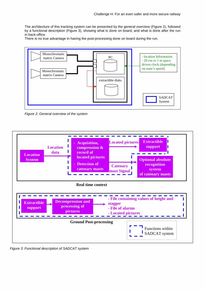
Figure 5: Example of detection output display, with a single contact wire
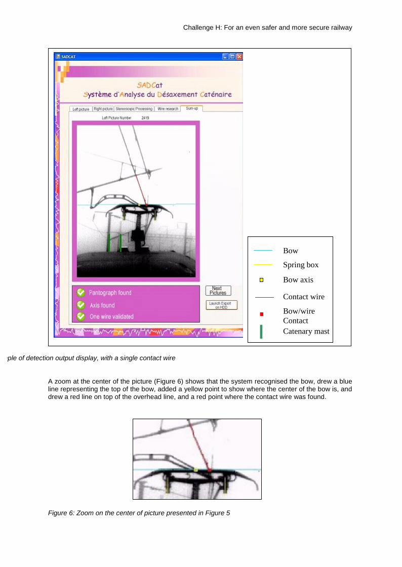
A zoom at the center of the picture (Figure 6) shows that the system recognised the bow, drew a blueline representing the top of the bow, added a yellow point to show where the center of the bow is, anddrew a red line on top of the overhead line, and a red point where the contact wire was found.
Figure 6: Zoom on the center of picture presented in Figure 5
Bow
Spring box
Bow axis
Contact wire
Bow/wireContactCatenary mast

Challenge H: For an even safer and more secure railway
Figure 7: Example of detection result even with an altered picture
Bow
Spring box
Bow axis
Contact wire
Bow/wireContactCatenary mast

Challenge H: For an even safer and more secure railway
Figure 8: Example of continuous detection result, even in a dual contact wire zone
Figure 9: Zoom on the center of picture presented in Figure 8
On IRIS 320, resolution is 6.4 mm per pixel, due to the distance between cameras and bow. Suddenchanges in light configuration are still an issue for visible matrix cameras. Feasibility should continuewith 2 thermal cameras in order to obtain continuous output, despite transition like tunnels or bridges.
BowSpring boxBow axis
Contact wireBow/wireContactCatenary mast

Challenge H: For an even safer and more secure railway
IV. The expected results
When the system is installed on a measurement engine:
Measures are done during periodic rounds or punctual measurement services already planned.
In addition, the combination of different specialised systems in the same engine allows performing amore complete diagnostic of the infrastructure (mixing different sources of catenary information suchas measurement of the catenary voltage under load or empty, detection of electric arcs, detection ofcatenary heat points thanks to thermography...).
This monitoring system is strategic to check that no defect in the OHL infrastructure could lead to amajor incident in line, from which it is always difficult to recover during commercial service.
An evolution to predictive maintenance could be possible if we were able to specify the evolution intime of stagger values. This would help to take decisions about maintenance or modernisationoperations.
While commercializing periodic or punctual runs of measurement engine abroad (in countries likeEngland, Belgium, Holland, Swiss, Deutschland, Italy…), this system would be an additional featurewithin commercial proposal since measurements are optimized.
Following incidents on the railway network, experts could investigate about the concerned portion ofline within archived data recorded before incident, and study its evolution. Those samples of datacould help to highlight defects which have led to incidents and understand why.
This system also generates a signal when the engine approachs catenary masts. This can be usefulfor improving the on-board location system, on electrified railway lines.
When the system is installed on rolling equipment currently in the process of being approved:
Safety requires a control of the dynamic interaction between pantograph and OHL during traffic test.The AEF (Railway Tests Agency) installs cameras on the roof of trains and records pictures.Within the framework of a potential partnership between the AEF and the Electric Tests LaboratoryDepartment, the system could also be installed and would add a useful function.
In both cases, the significant reduction of issues and defects on OHL infrastructure will lead to adecrease of maintenance costs and help trains to meet their planned schedule.