Embed Size (px)
Citation preview
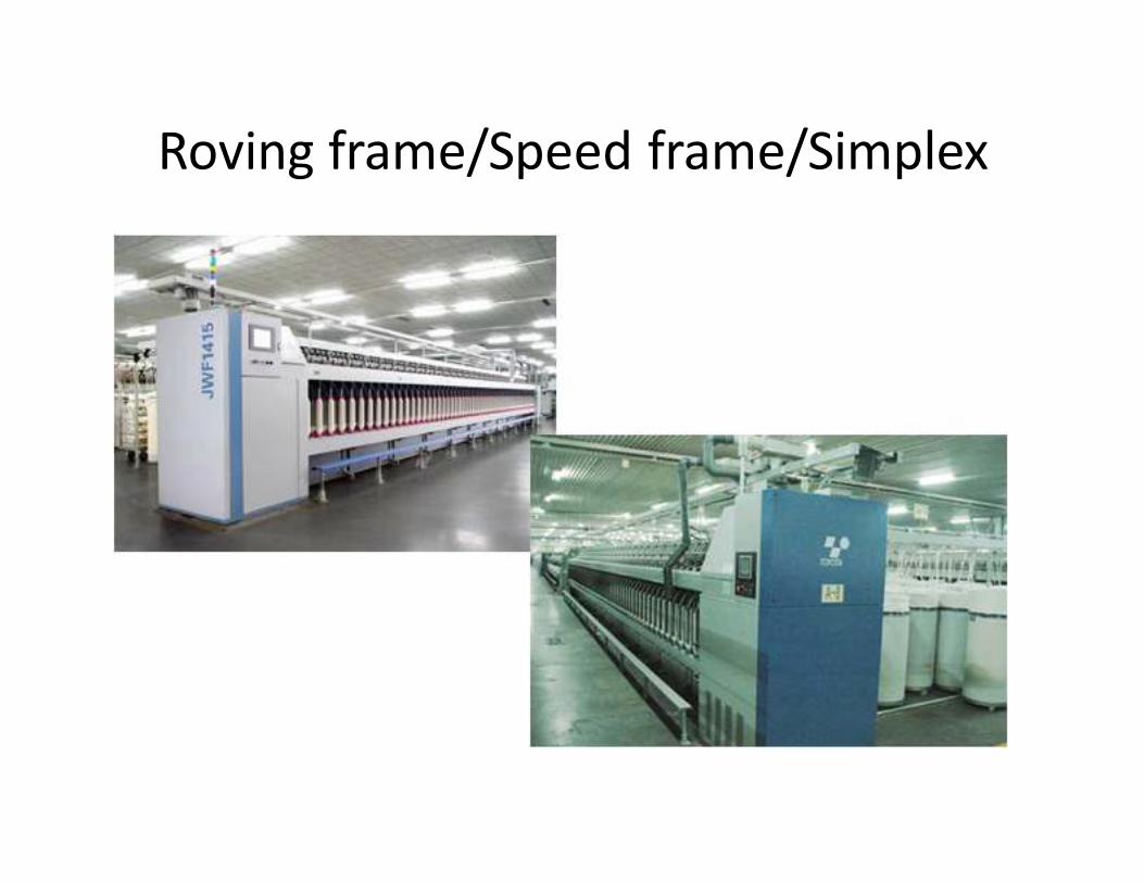
Roving frame/Speed frame/Simplex
Function/objectives/What it does?
• The chief function of roving frame is the attenuation of sliver.
• Insertion of protective twist in order to hold the fine strand of
sliver.
• Winding of roving into a package that can be transported, sorted, donned on ring spinning machine.
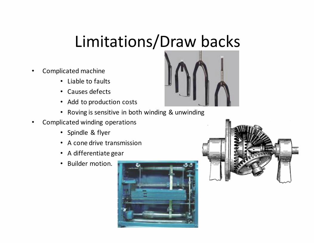
Limitations/Draw backs
• Complicated machine
• Liable to faults
• Causes defects
• Add to production costs
• Roving is sensitive in both winding & unwinding
• Complicated winding operations
• Spindle & flyer
• A cone drive transmission
• A differentiate gear
• Builder motion.
Necessity of Roving Frame
• There are two principle reason:
– First reason is to apply drafting. – Sliver is thick, untwisted strand that tends to be hairy and to
create fly. There fore, if we directly want to produce yarn from
sliver by discarding simplex, we need 300 to 500 draft to do
so. But the fine twisted roving is significantly better suited to
this purpose.
– Second reason is related with transportation and
space limitation on ring frame. – Draw frame “can” is the worst conceivable mode of
transportation and presentation of feed material.
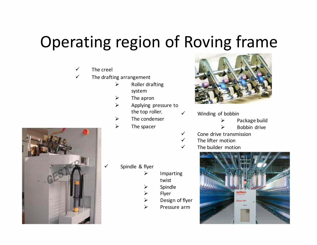
Operating region of Roving frame
� The creel
� The drafting arrangement
� Roller drafting
system
� The apron
� Applying pressure to
the top roller.
� The condenser
� The spacer
� Winding of bobbin
� Package build
� Bobbin drive
� Cone drive transmission
� The lifter motion
� The builder motion
� Spindle & flyer
� Imparting
twist
� Spindle
� Flyer
� Design of flyer
� Pressure arm
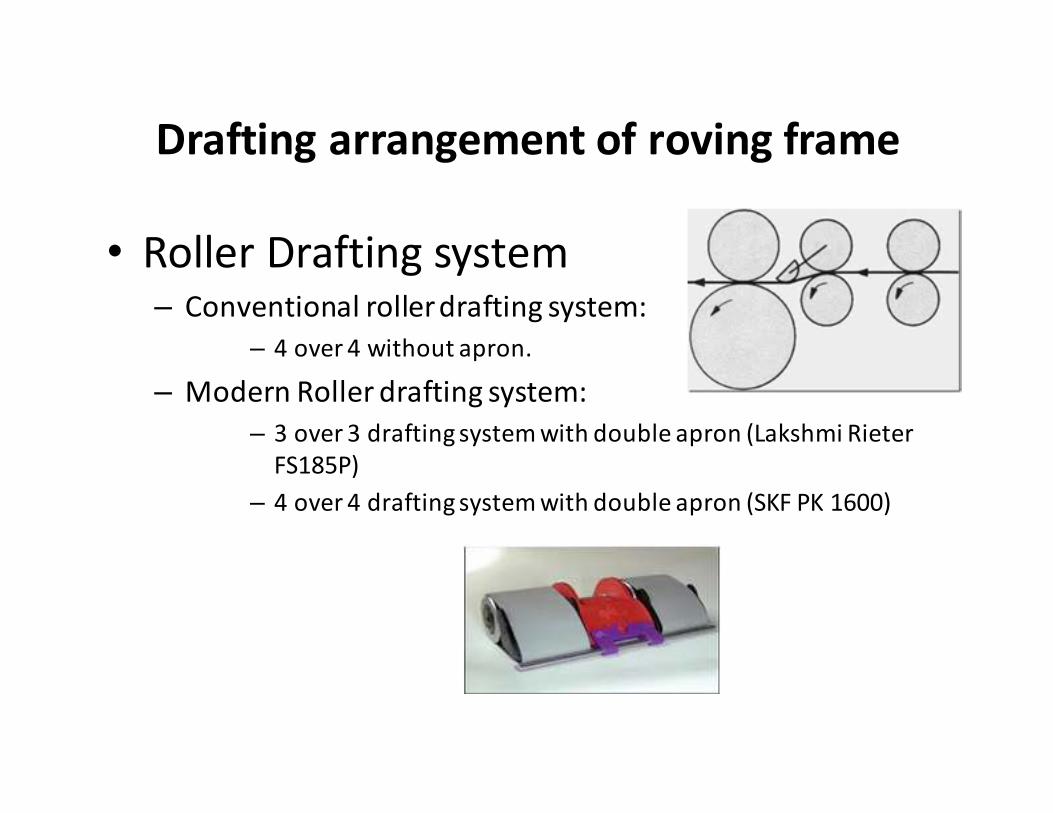
Drafting arrangement of roving frame
• Roller Drafting system – Conventional roller drafting system:
– 4 over 4 without apron.
– Modern Roller drafting system:
– 3 over 3 drafting system with double apron (Lakshmi Rieter
FS185P)
– 4 over 4 drafting system with double apron (SKF PK 1600)
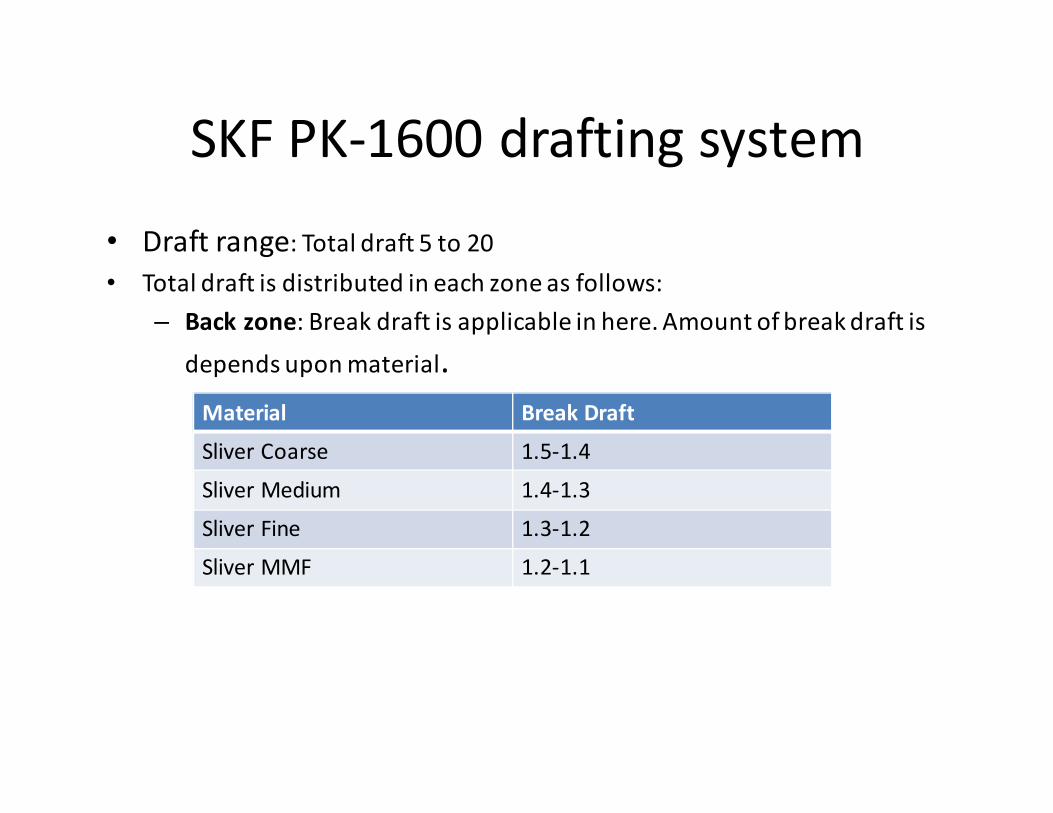
SKF PK-1600 drafting system
• Draft range: Total draft 5 to 20
• Total draft is distributed in each zone as follows:
– Back zone: Break draft is applicable in here. Amount of break draft is
depends upon material.
Material Break Draft
Sliver Coarse 1.5-1.4
Sliver Medium 1.4-1.3
Sliver Fine 1.3-1.2
Sliver MMF 1.2-1.1
• Middle zone: – Less amount draft is applicable in here.
– Condenser is used in middle zone to condense sheet like sliver.
• Front zone:
– Maximum amount of draft is applicable in here. Apron is
used in this zone.
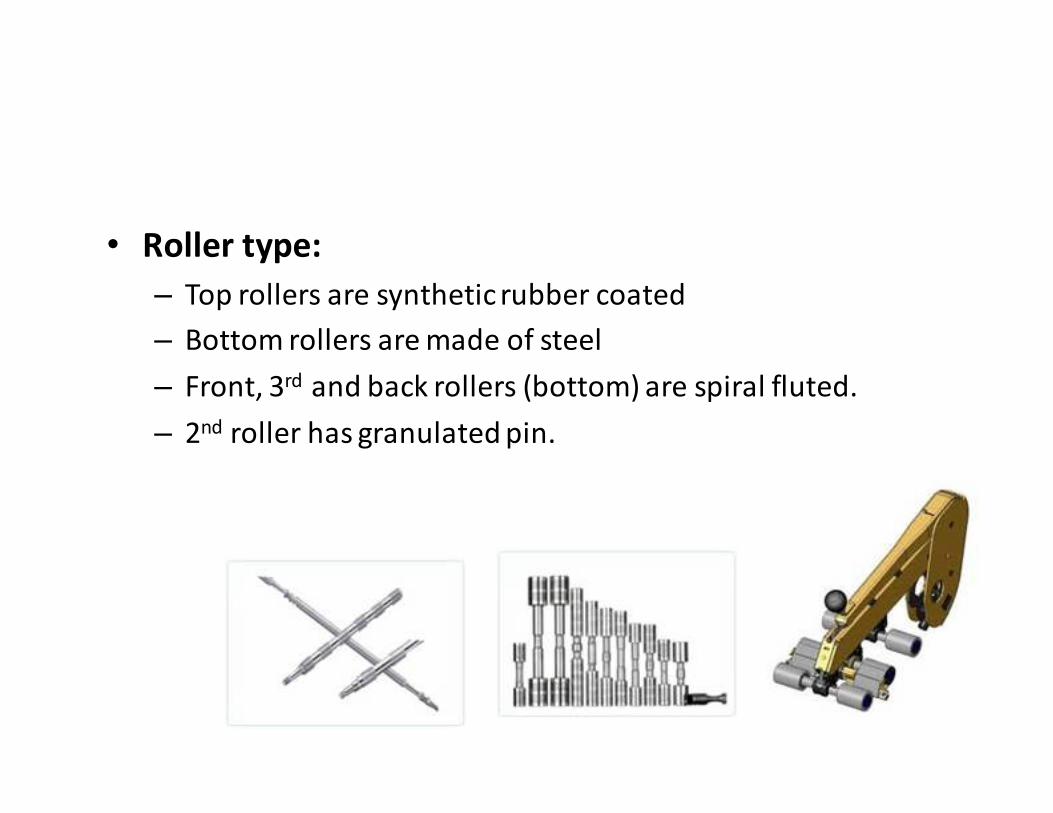
• Roller type:
– Top rollers are synthetic rubber coated
– Bottom rollers are made of steel
– Front, 3rd and back rollers (bottom) are spiral fluted.
– 2nd roller has granulated pin.
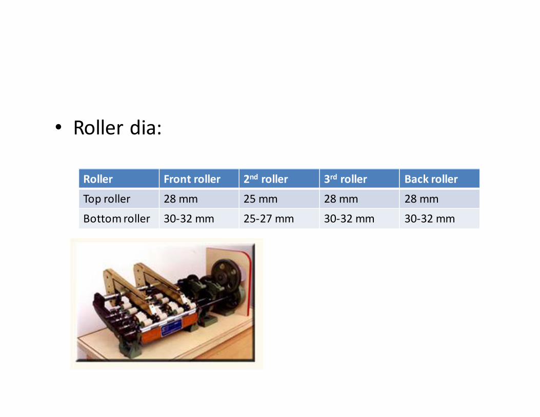
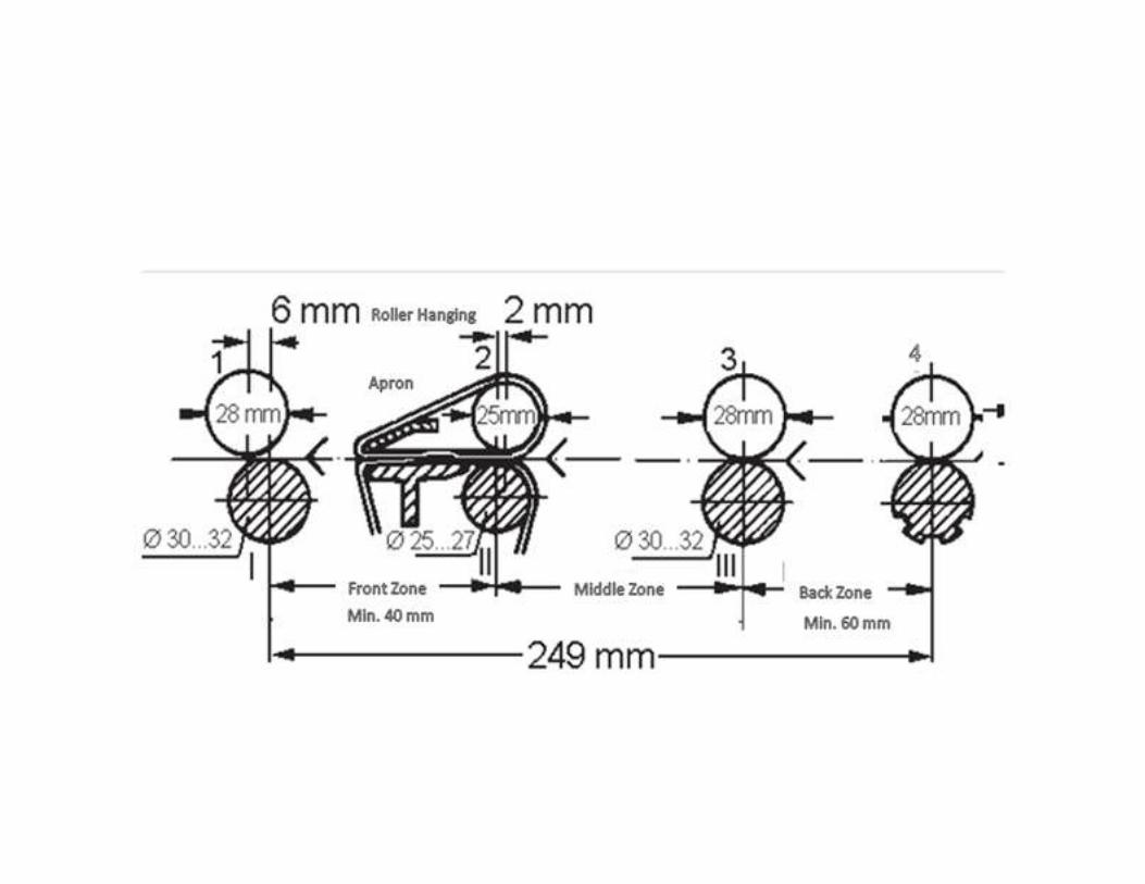
• Roller dia:
Roller Front roller 2nd roller 3rd roller Back roller
Top roller 28 mm 25 mm 28 mm 28 mm
Bottom roller 30-32 mm 25-27 mm 30-32 mm 30-32 mm
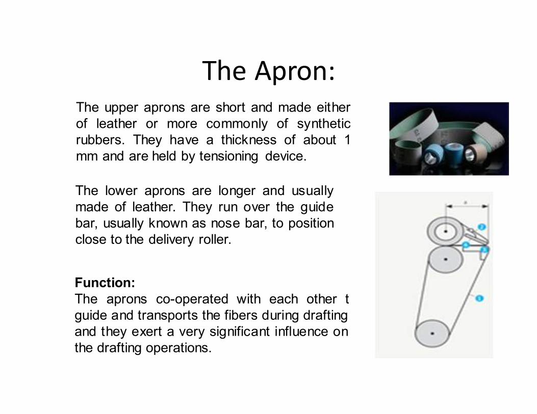
The Apron: The upper aprons are short and made either
of leather or more commonly of synthetic
rubbers. They have a thickness of about 1
mm and are held by tensioning device.
The lower aprons are longer and usually
made of leather. They run over the guide
bar, usually known as nose bar, to position
close to the delivery roller.
Function:
The aprons co-operated with each other t
guide and transports the fibers during drafting
and they exert a very significant influence on
the drafting operations.
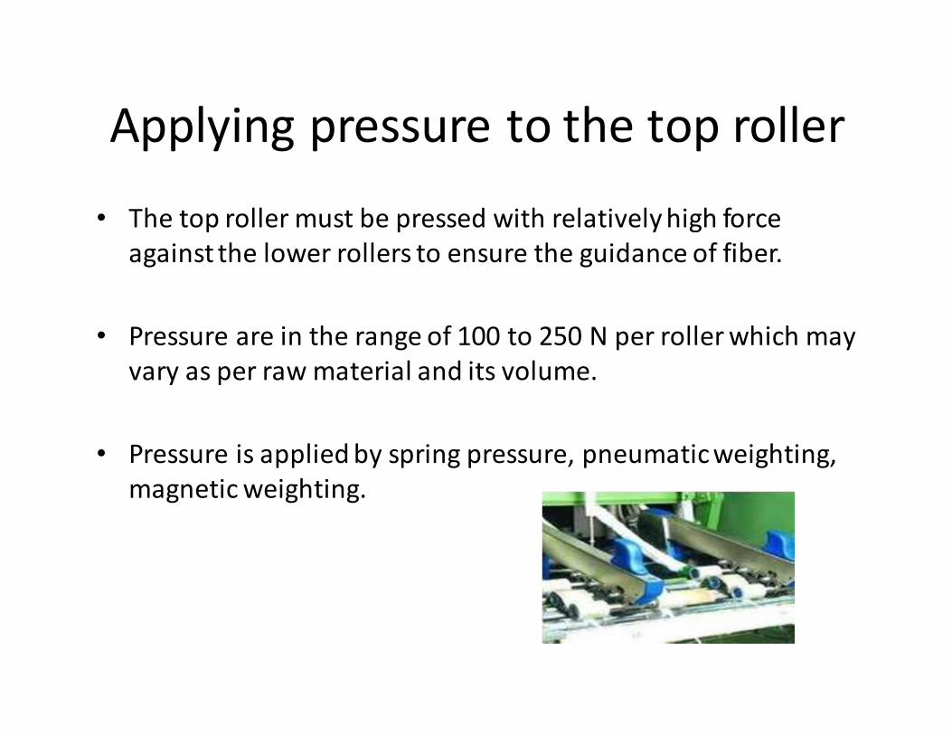
Applying pressure to the top roller
• The top roller must be pressed with relatively high force
against the lower rollers to ensure the guidance of fiber.
• Pressure are in the range of 100 to 250 N per roller which may
vary as per raw material and its volume.
• Pressure is applied by spring pressure, pneumatic weighting,
magnetic weighting.
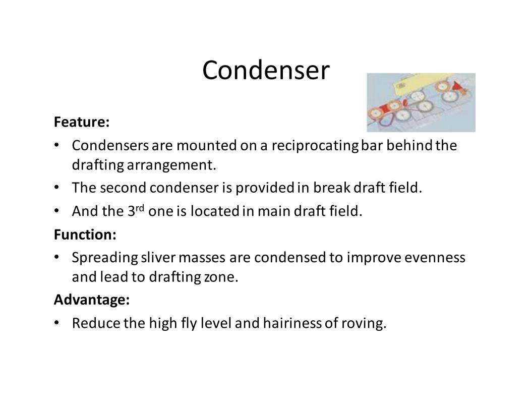
Condenser
Feature:
• Condensers are mounted on a reciprocating bar behind the
drafting arrangement.
• The second condenser is provided in break draft field.
• And the 3rd one is located in main draft field.
Function:
• Spreading sliver masses are condensed to improve evenness
and lead to drafting zone.
Advantage:
• Reduce the high fly level and hairiness of roving.
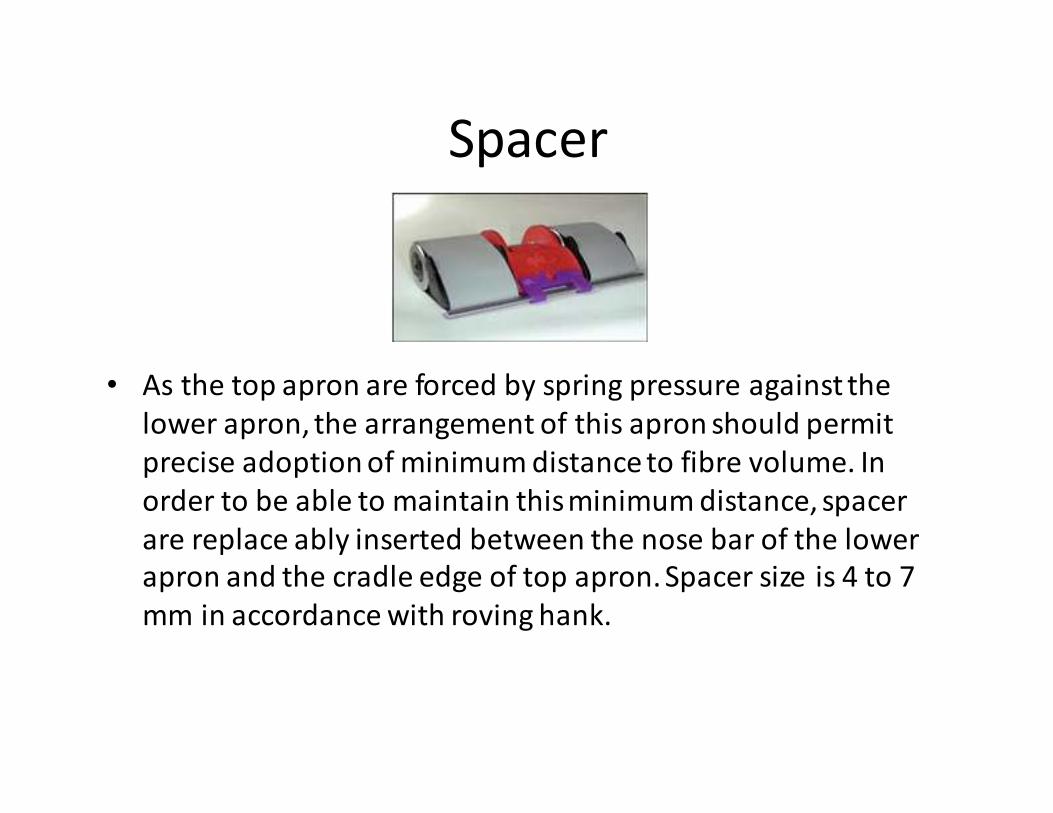
Spacer
• As the top apron are forced by spring pressure against the
lower apron, the arrangement of this apron should permit
precise adoption of minimum distance to fibre volume. In
order to be able to maintain this minimum distance, spacer
are replace ably inserted between the nose bar of the lower
apron and the cradle edge of top apron. Spacer size is 4 to 7
mm in accordance with roving hank.
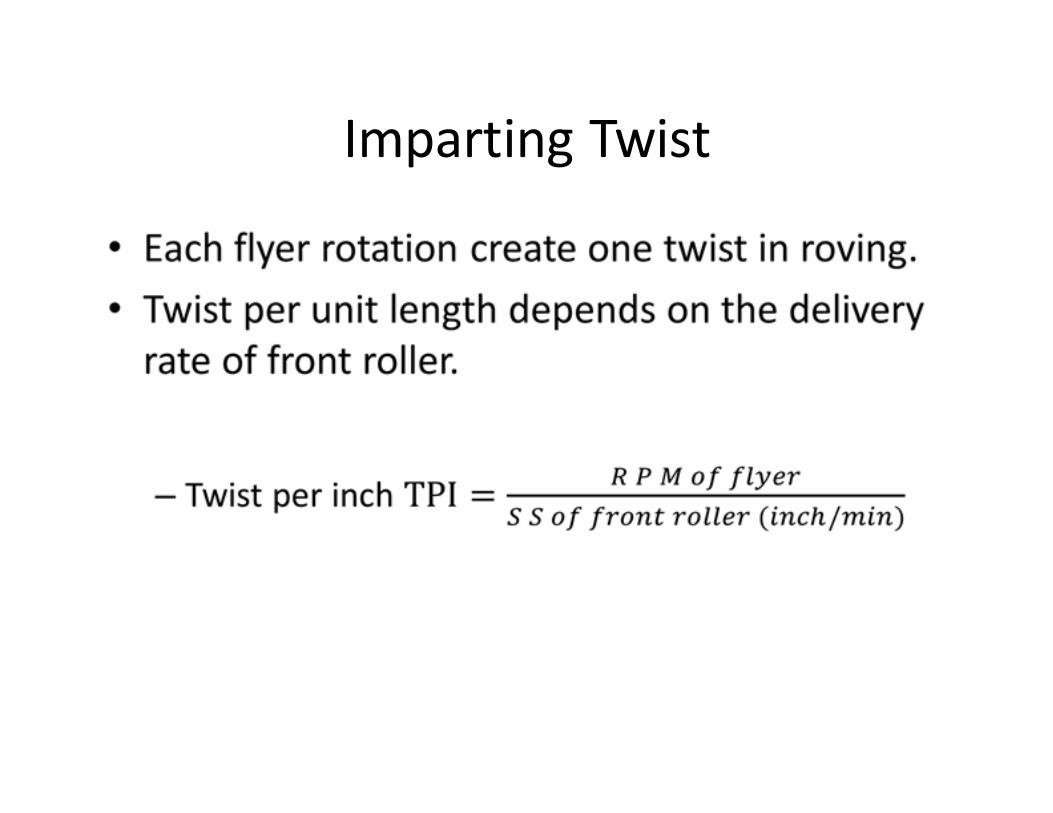
Imparting Twist
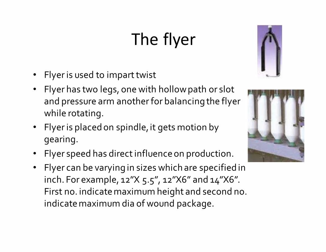
The flyer
• Flyer is used to impart twist
• Flyer has two legs, one with hollow path or slot
and pressure arm another for balancing the flyer
while rotating.
• Flyer is placed on spindle, it gets motion by
gearing.
• Flyer speed has direct influence on production.
• Flyer can be varying in sizes which are specified in
inch. For example, 12”X 5.5”, 12”X6” and 14”X6”.
First no. indicate maximum height and second no.
indicate maximum dia of wound package.
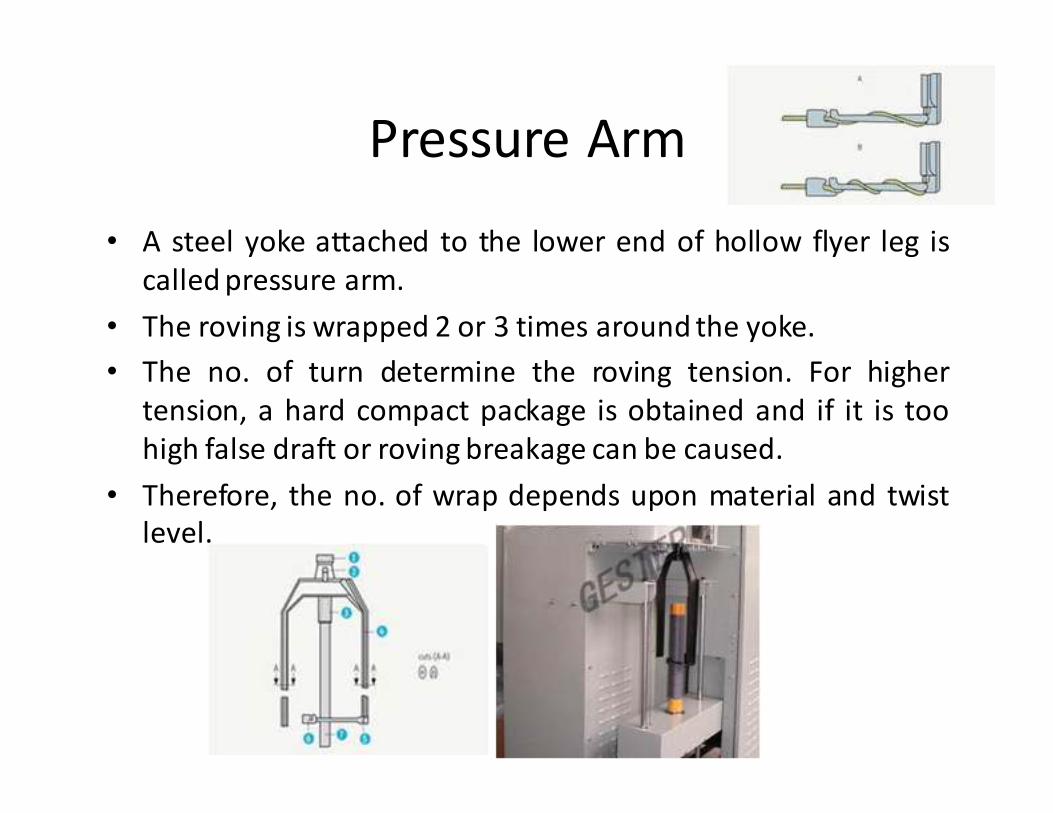
Pressure Arm
• A steel yoke attached to the lower end of hollow flyer leg is
called pressure arm.
• The roving is wrapped 2 or 3 times around the yoke.
• The no. of turn determine the roving tension. For higher
tension, a hard compact package is obtained and if it is too
high false draft or roving breakage can be caused.
• Therefore, the no. of wrap depends upon material and twist
level.
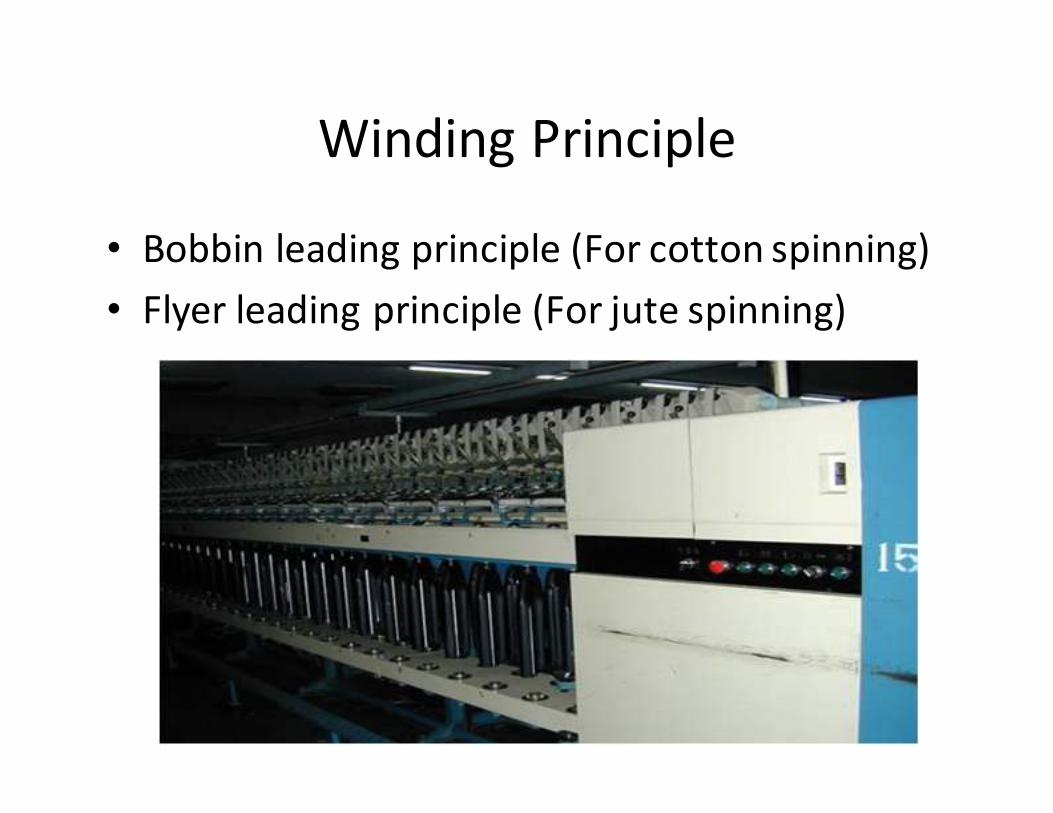
Winding Principle
• Bobbin leading principle (For cotton spinning)
• Flyer leading principle (For jute spinning)
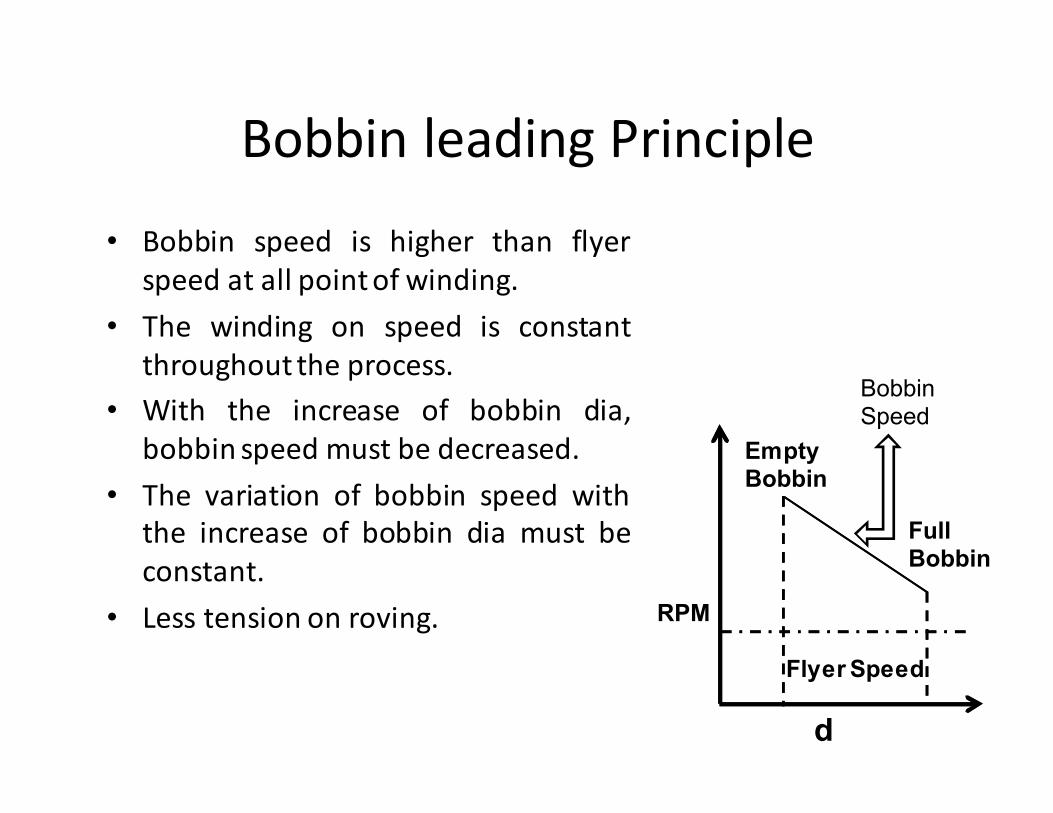
Bobbin leading Principle
• Bobbin speed is higher than flyer
speed at all point of winding.
• The winding on speed is constant
throughout the process.
• With the increase of bobbin dia,
bobbin speed must be decreased.
• The variation of bobbin speed with
the increase of bobbin dia must be
constant.
• Less tension on roving. RPM
d
Empty Bobbin
Full Bobbin
Bobbin Speed
Flyer Speed
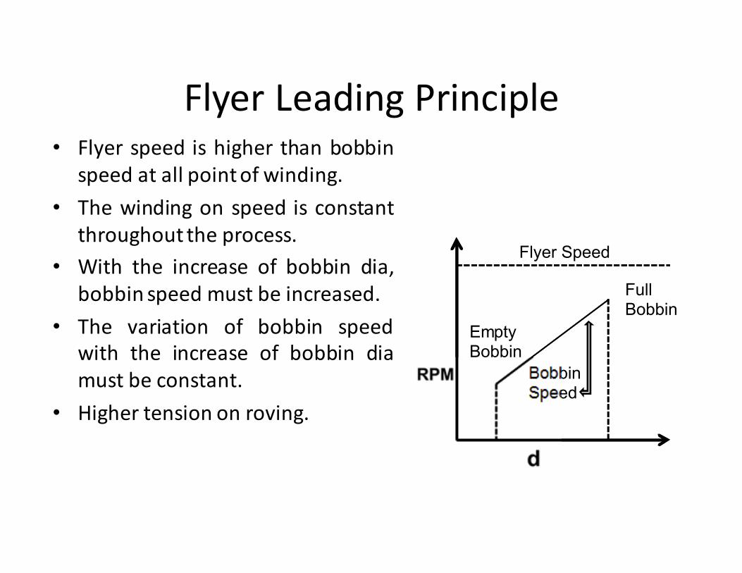
Flyer Leading Principle
Flyer Speed
Empty Bobbin
Full Bobbin
Bobbin Speed
• Flyer speed is higher than bobbin
speed at all point of winding.
• The winding on speed is constant
throughout the process.
• With the increase of bobbin dia,
bobbin speed must be increased.
• The variation of bobbin speed
with the increase of bobbin dia
must be constant.
• Higher tension on roving.
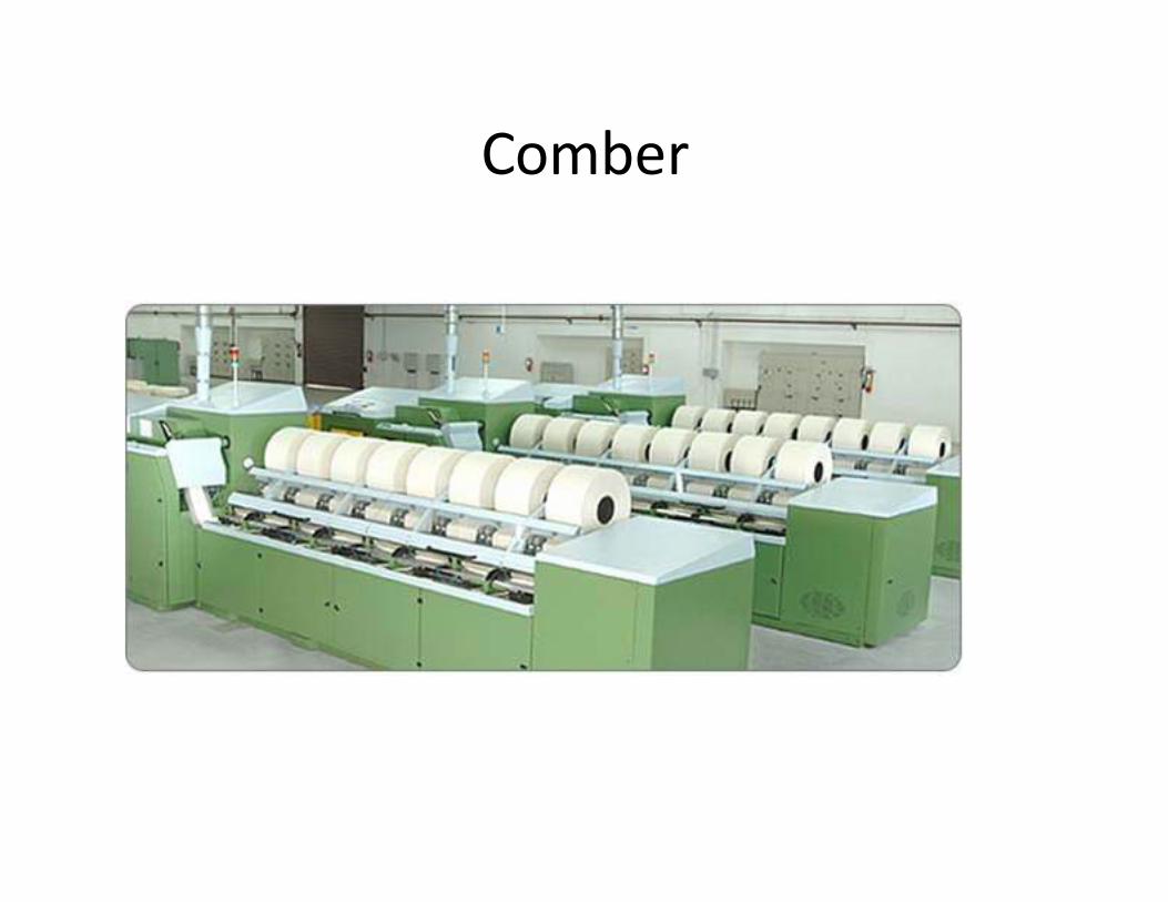
Comber
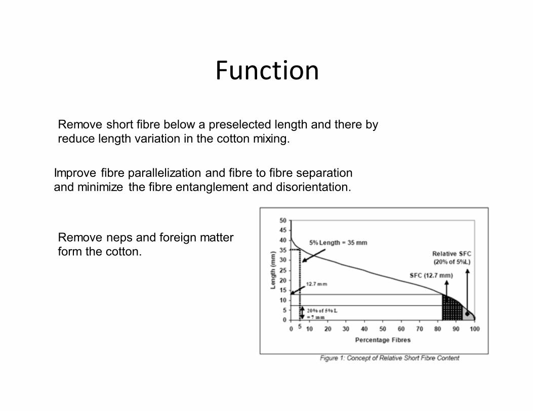
Function
Remove neps and foreign matter form the cotton.
Improve fibre parallelization and fibre to fibre separation and minimize the fibre entanglement and disorientation.
Remove short fibre below a preselected length and there by reduce length variation in the cotton mixing.
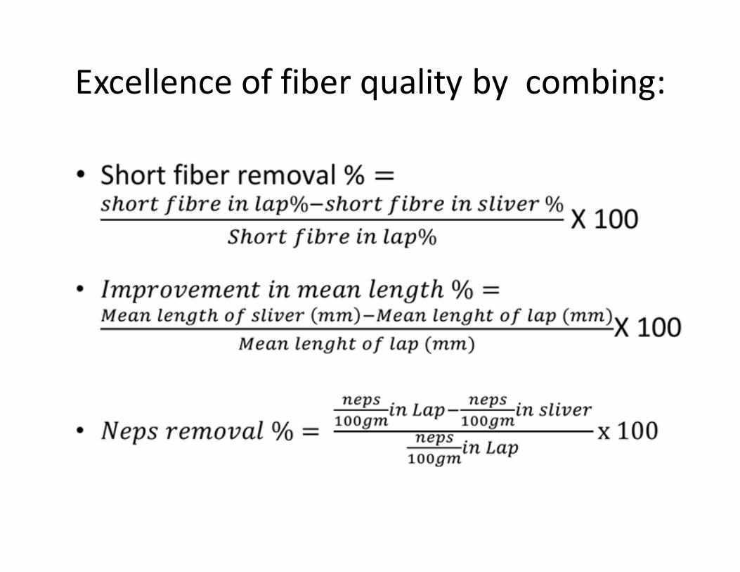
Excellence of fiber quality by combing:
Parameter/ Specification of
comber
• Feed/nips 6-8 mm
• Nips/min 220-600
• Lap weight 800-1200 grs/yd
• Noil % 10-25%
• Efficiency 90-95%
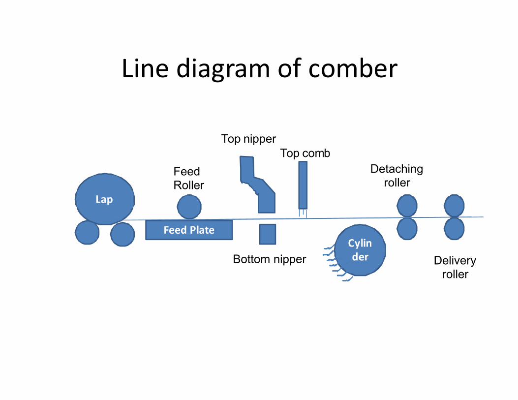
Line diagram of comber
Lap
Feed Plate
Cylin
der
Feed Roller
Top nipper
Bottom nipper
Top comb
Detaching roller
Delivery roller
Machine Setting Depends on Noil Extraction%
• Feed Distance
• Type of feed
• Detachment setting
• Point density on top combs
• Piecing
Feed Distance:
– Feed distance means feed per nip.
– Feed distance has a influence on
• Noil
• Quality of combing operation
• Production rate.
�High feed distance increase the production rate
but causes deterioration in quality.
�Feed distance approximately correlated with fibre length.
Type of feed
• Forward feed has been chosen for higher production rate
when quality requirement is not rigorous with a noil % of
5- 12 %.
• Backward feed has to use for higher quality requirement
with a noil % of 12 to 25%
The detachment setting
• This is the distance between the bite of the
nippers and the nip line of detaching rollers.
• Higher detachment setting bring the high elimination
of noil
• The detachment setting normally lies in the
range of 15 to 25 mm.
The no. of points on comb
• Point density and the fineness of needle have to be adopted to the material.


![[3.5 Monster Class] Roving Mauler](https://img.pdfslide.us/doc/110x75/55cf9a9d550346d033a2973a/35-monster-class-roving-mauler.jpg)