Embed Size (px)
Citation preview
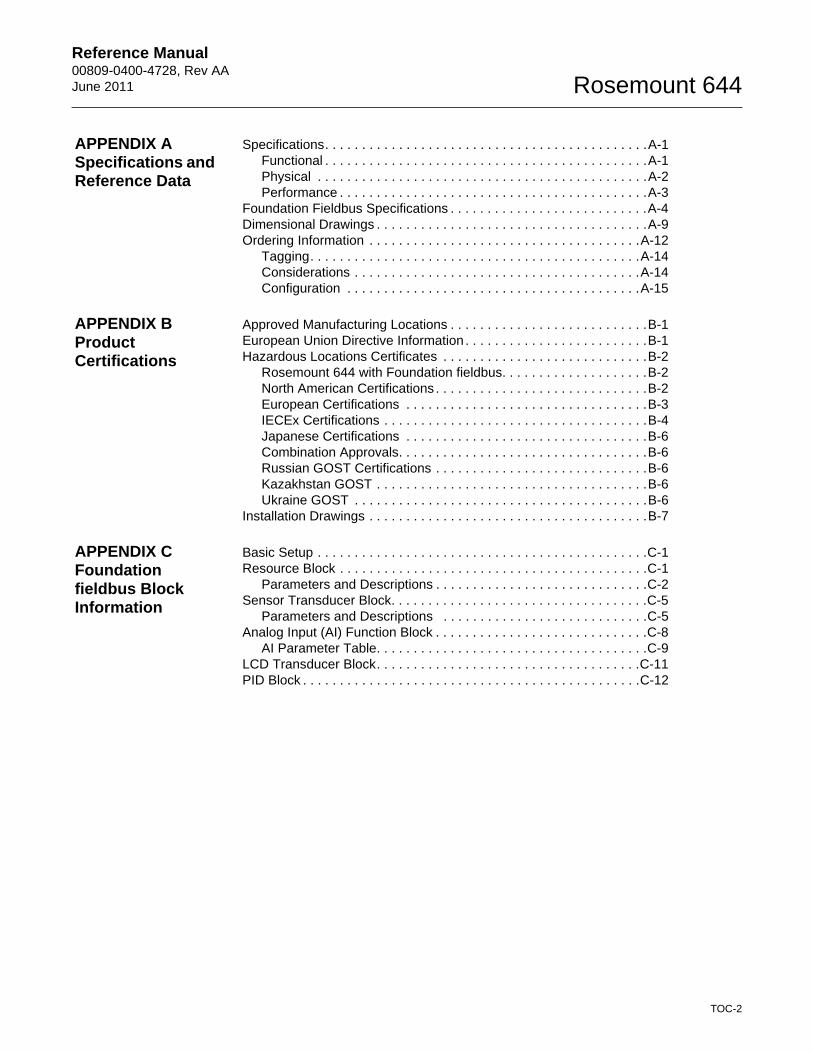
Reference Manual 00809-0400-4728, Rev AAJune 2011
Rosemount 644 Temperature Transmitter with FOUNDATION™ fieldbus
www.rosemount.com

Reference Manual00809-0400-4728, Rev AA
June 2011Rosemount 644
Table of Contents
SECTION 1Introduction
Safety Messages . . . . . . . . . . . . . . . . . . . . . . . . . . . . . . . . . . . . . . . . . 1-1Warnings . . . . . . . . . . . . . . . . . . . . . . . . . . . . . . . . . . . . . . . . . . . . 1-1
Overview . . . . . . . . . . . . . . . . . . . . . . . . . . . . . . . . . . . . . . . . . . . . . . . 1-2Manual . . . . . . . . . . . . . . . . . . . . . . . . . . . . . . . . . . . . . . . . . . . . . . 1-2Transmitter . . . . . . . . . . . . . . . . . . . . . . . . . . . . . . . . . . . . . . . . . . . 1-2
Considerations. . . . . . . . . . . . . . . . . . . . . . . . . . . . . . . . . . . . . . . . . . . 1-3General. . . . . . . . . . . . . . . . . . . . . . . . . . . . . . . . . . . . . . . . . . . . . . 1-3Commissioning . . . . . . . . . . . . . . . . . . . . . . . . . . . . . . . . . . . . . . . . 1-3Mechanical . . . . . . . . . . . . . . . . . . . . . . . . . . . . . . . . . . . . . . . . . . . 1-3Electrical . . . . . . . . . . . . . . . . . . . . . . . . . . . . . . . . . . . . . . . . . . . . . 1-3Environmental. . . . . . . . . . . . . . . . . . . . . . . . . . . . . . . . . . . . . . . . . 1-3
Return of Materials . . . . . . . . . . . . . . . . . . . . . . . . . . . . . . . . . . . . . . . 1-4Product Recycling/Disposal . . . . . . . . . . . . . . . . . . . . . . . . . . . . . . . . . 1-4
SECTION 2Installation
Safety Messages . . . . . . . . . . . . . . . . . . . . . . . . . . . . . . . . . . . . . . . . . 2-1Warnings . . . . . . . . . . . . . . . . . . . . . . . . . . . . . . . . . . . . . . . . . . . . 2-1
Mounting . . . . . . . . . . . . . . . . . . . . . . . . . . . . . . . . . . . . . . . . . . . . . . . 2-3Installation . . . . . . . . . . . . . . . . . . . . . . . . . . . . . . . . . . . . . . . . . . . . . . 2-4
Typical European Installation . . . . . . . . . . . . . . . . . . . . . . . . . . . . . 2-4Typical North American Installation . . . . . . . . . . . . . . . . . . . . . . . . 2-5LCD Display Installation . . . . . . . . . . . . . . . . . . . . . . . . . . . . . . . . . 2-6
Wiring. . . . . . . . . . . . . . . . . . . . . . . . . . . . . . . . . . . . . . . . . . . . . . . . . . 2-7Sensor Connections . . . . . . . . . . . . . . . . . . . . . . . . . . . . . . . . . . . . 2-8
Power Supply. . . . . . . . . . . . . . . . . . . . . . . . . . . . . . . . . . . . . . . . . . . 2-11Ground the Transmitter . . . . . . . . . . . . . . . . . . . . . . . . . . . . . . . . 2-11
SECTION 3Configuration
Overview . . . . . . . . . . . . . . . . . . . . . . . . . . . . . . . . . . . . . . . . . . . . . . . 3-1Safety Messages . . . . . . . . . . . . . . . . . . . . . . . . . . . . . . . . . . . . . . . . . 3-1
Warnings . . . . . . . . . . . . . . . . . . . . . . . . . . . . . . . . . . . . . . . . . . . . 3-1General Block Information . . . . . . . . . . . . . . . . . . . . . . . . . . . . . . . . . . 3-2
Device Description . . . . . . . . . . . . . . . . . . . . . . . . . . . . . . . . . . . . . 3-2Node Address. . . . . . . . . . . . . . . . . . . . . . . . . . . . . . . . . . . . . . . . . 3-2Modes. . . . . . . . . . . . . . . . . . . . . . . . . . . . . . . . . . . . . . . . . . . . . . . 3-2Link Active Scheduler . . . . . . . . . . . . . . . . . . . . . . . . . . . . . . . . . . . 3-3Block Installation. . . . . . . . . . . . . . . . . . . . . . . . . . . . . . . . . . . . . . . 3-3Capabilities . . . . . . . . . . . . . . . . . . . . . . . . . . . . . . . . . . . . . . . . . . . 3-4
Foundation fieldbus function blocks. . . . . . . . . . . . . . . . . . . . . . . . . . . 3-4Resource Block . . . . . . . . . . . . . . . . . . . . . . . . . . . . . . . . . . . . . . . 3-5Sensor Transducer Block . . . . . . . . . . . . . . . . . . . . . . . . . . . . . . . . 3-9Analog Input (AI) Function Block . . . . . . . . . . . . . . . . . . . . . . . . . . 3-9LCD Transducer Block . . . . . . . . . . . . . . . . . . . . . . . . . . . . . . . . . 3-14
Operation and Maintenance . . . . . . . . . . . . . . . . . . . . . . . . . . . . . . . 3-15Overview. . . . . . . . . . . . . . . . . . . . . . . . . . . . . . . . . . . . . . . . . . . . 3-15Troubleshooting Guides . . . . . . . . . . . . . . . . . . . . . . . . . . . . . . . . 3-16Sensor Transducer Block . . . . . . . . . . . . . . . . . . . . . . . . . . . . . . . 3-18Analog Input (AI) Function Block . . . . . . . . . . . . . . . . . . . . . . . . . 3-21Resource Block . . . . . . . . . . . . . . . . . . . . . . . . . . . . . . . . . . . . . . 3-23LCD Transducer block . . . . . . . . . . . . . . . . . . . . . . . . . . . . . . . . . 3-24
TOC-1
Reference Manual 00809-0400-4728, Rev AAJune 2011 Rosemount 644
APPENDIX ASpecifications and Reference Data
Specifications. . . . . . . . . . . . . . . . . . . . . . . . . . . . . . . . . . . . . . . . . . . .A-1Functional . . . . . . . . . . . . . . . . . . . . . . . . . . . . . . . . . . . . . . . . . . . .A-1Physical . . . . . . . . . . . . . . . . . . . . . . . . . . . . . . . . . . . . . . . . . . . . .A-2Performance . . . . . . . . . . . . . . . . . . . . . . . . . . . . . . . . . . . . . . . . . .A-3
Foundation Fieldbus Specifications . . . . . . . . . . . . . . . . . . . . . . . . . . .A-4Dimensional Drawings . . . . . . . . . . . . . . . . . . . . . . . . . . . . . . . . . . . . .A-9Ordering Information . . . . . . . . . . . . . . . . . . . . . . . . . . . . . . . . . . . . .A-12
Tagging. . . . . . . . . . . . . . . . . . . . . . . . . . . . . . . . . . . . . . . . . . . . .A-14Considerations . . . . . . . . . . . . . . . . . . . . . . . . . . . . . . . . . . . . . . .A-14Configuration . . . . . . . . . . . . . . . . . . . . . . . . . . . . . . . . . . . . . . . .A-15
APPENDIX BProduct Certifications
Approved Manufacturing Locations . . . . . . . . . . . . . . . . . . . . . . . . . . .B-1European Union Directive Information . . . . . . . . . . . . . . . . . . . . . . . . .B-1Hazardous Locations Certificates . . . . . . . . . . . . . . . . . . . . . . . . . . . .B-2
Rosemount 644 with Foundation fieldbus. . . . . . . . . . . . . . . . . . . .B-2North American Certifications . . . . . . . . . . . . . . . . . . . . . . . . . . . . .B-2European Certifications . . . . . . . . . . . . . . . . . . . . . . . . . . . . . . . . .B-3IECEx Certifications . . . . . . . . . . . . . . . . . . . . . . . . . . . . . . . . . . . .B-4Japanese Certifications . . . . . . . . . . . . . . . . . . . . . . . . . . . . . . . . .B-6Combination Approvals. . . . . . . . . . . . . . . . . . . . . . . . . . . . . . . . . .B-6Russian GOST Certifications . . . . . . . . . . . . . . . . . . . . . . . . . . . . .B-6Kazakhstan GOST . . . . . . . . . . . . . . . . . . . . . . . . . . . . . . . . . . . . .B-6Ukraine GOST . . . . . . . . . . . . . . . . . . . . . . . . . . . . . . . . . . . . . . . .B-6
Installation Drawings . . . . . . . . . . . . . . . . . . . . . . . . . . . . . . . . . . . . . .B-7
APPENDIX CFoundation fieldbus Block Information
Basic Setup . . . . . . . . . . . . . . . . . . . . . . . . . . . . . . . . . . . . . . . . . . . . .C-1Resource Block . . . . . . . . . . . . . . . . . . . . . . . . . . . . . . . . . . . . . . . . . .C-1
Parameters and Descriptions . . . . . . . . . . . . . . . . . . . . . . . . . . . . .C-2Sensor Transducer Block. . . . . . . . . . . . . . . . . . . . . . . . . . . . . . . . . . .C-5
Parameters and Descriptions . . . . . . . . . . . . . . . . . . . . . . . . . . . .C-5Analog Input (AI) Function Block . . . . . . . . . . . . . . . . . . . . . . . . . . . . .C-8
AI Parameter Table. . . . . . . . . . . . . . . . . . . . . . . . . . . . . . . . . . . . .C-9LCD Transducer Block. . . . . . . . . . . . . . . . . . . . . . . . . . . . . . . . . . . .C-11PID Block . . . . . . . . . . . . . . . . . . . . . . . . . . . . . . . . . . . . . . . . . . . . . .C-12
TOC-2
Reference Manual 00809-0400-4728, Rev AAJune 2011 Rosemount 644
Rosemount 644 Temperature Transmitters
Rosemount 644 Hardware RevisionFOUNDATION™ Fieldbus Device RevisionDevice Descriptor Revision921
NOTICE
Read this manual before working with the product. For personal and system safety, and for optimum product performance, make sure to thoroughly understand the contents before installing, using, or maintaining this product.
The United States has two toll-free assistance numbers and one international number.
Customer Central1-800-999-9307 (7:00 a.m. to 7:00 p.m. CST)
National Response Center1-800-654-7768 (24 hours a day)Equipment service needs
International1-(952)-906-8888
The products described in this document are NOT designed for nuclear-qualified applications.
Using non-nuclear qualified products in applications that require nuclear-qualified hardware or products may cause inaccurate readings.
For information on Rosemount nuclear-qualified products, contact a Emerson Process Management Sales Representative.
www.rosemount.com

Reference Manual 00809-0400-4728, Rev AAJune 2011 Rosemount 644
Section 1 Introduction
Safety Messages . . . . . . . . . . . . . . . . . . . . . . . . . . . . . . . . . page 1-1Overview . . . . . . . . . . . . . . . . . . . . . . . . . . . . . . . . . . . . . . . page 1-2Considerations . . . . . . . . . . . . . . . . . . . . . . . . . . . . . . . . . . page 1-3Return of Materials . . . . . . . . . . . . . . . . . . . . . . . . . . . . . . . page 1-4
SAFETY MESSAGES Instructions and procedures in this section may require special precautions to ensure the safety of the personnel performing the operations. Information that potentially raises safety issues is indicated by a warning symbol ( ). Please refer to the following safety messages before performing an operation preceded by this symbol.
Warnings
Failure to follow these installation guidelines could result in death orserious injury.
• Make sure only qualified personnel perform the installation.
Explosions could result in death or serious injury.
• Do not remove the connection head cover in explosive atmospheres when the circuit is live.
• Before connecting FOUNDATION fieldbus in an explosive atmosphere, make sure the instruments in the loop are installed in accordance with intrinsically safe or non-intrinsic field wiring practices.
• Verify that the operating atmosphere of the transmitter is consistent with the appropriate hazardous locations certifications.
• All connection head covers must be fully engaged to meet explosion-proof requirements.
Process leaks could result in death or serious injury.
• Do not remove the thermowell while in operation.
• Install and tighten thermowells and sensors before applying pressure.
Electrical shock could cause death or serious injury.
• Use extreme caution when making contact with the leads and terminals.
www.rosemount.com
Reference Manual00809-0400-4728, Rev AA
June 2011Rosemount 644
OVERVIEW
Manual This manual is designed to assist in the installation, operation, and maintenance of Rosemount 644 head mount and 644 rail mount.
Section 1: Introduction
• Transmitter and Manual Overview
• Considerations
• Return of Material
Section 2: Installation
• Mounting
• Installation
• Wiring
• Power Supply
• Commissioning
Section 3: Configuration
• Calibration
• Hardware Maintenance
• Diagnostic Messaging
Appendix A: Specifications and Reference Data
• Specifications
• Dimensional Drawings
• Ordering Information
• Biotechnology, Pharmaceutical Industries, and Sanitary Applications
Appendix B: Product Certifications
• Product Certifications
• Installation Drawings
Appendix C: Foundation fieldbus Block Information
• Information regarding the Function Blocks
Transmitter Features of the Rosemount 644 include:
• Accepts inputs from a wide variety of sensors
• Configuration using FOUNDATION fieldbus
• Electronics that are completely encapsulated in epoxy and enclosed in a metal housing, making the transmitter extremely durable and ensuring long-term reliability
• A compact size and two housing options allowing mounting flexibility for the control room or the field
1-2
Reference Manual 00809-0400-4728, Rev AAJune 2011 Rosemount 644
Refer to the following literature for a full range of compatible connection heads, sensors, and thermowells provided by Emerson Process Management.
• Temperature Sensors and Assemblies Product Data Sheet, Volume 1 (document number 00813-0100-2654)
• Temperature Sensors and Assemblies Product Data Sheet, Volume 2 (document number 00813-0200-2654)
CONSIDERATIONS
General Electrical temperature sensors such as RTDs and thermocouples produce low-level signals proportional to their sensed temperature. The 644 converts the low-level sensor signal to a standard 4–20 mA dc, or digital FOUNDATION fieldbus signal that is relatively insensitive to lead length and electrical noise. This signal is then transmitted to the control room via two wires.
Commissioning The transmitter can be commissioned before or after installation. It may be useful to commission it on the bench, before installation, to ensure proper operation and to become familiar with its functionality. Make sure the instruments in the loop are installed in accordance with intrinsically safe, FISCO, or non-incendive field wiring practices.
Mechanical Location
When choosing an installation location and position, take into account the need for access to the transmitter.
Special Mounting
Special mounting hardware is available for mounting a 644 head mount transmitter to a DIN rail or assembling a new 644 head mount to an existing threaded sensor connection head (former option code L1).
Electrical Proper electrical installation is necessary to prevent errors due to sensor lead resistance and electrical noise. For best results, shielded cable should be used in electrically noisy environments.
Make wiring connections through the cable entry in the side of the connection head. Be sure to provide adequate clearance for cover removal.
Environmental The transmitter electronics module is permanently sealed within the housing, resisting moisture and corrosive damage. Verify that the operating atmosphere of the transmitter is consistent with the appropriate hazardous locations certifications.
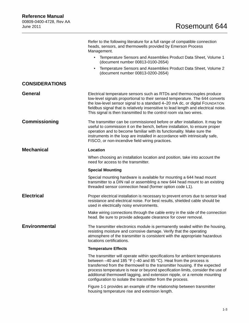
Temperature Effects
The transmitter will operate within specifications for ambient temperatures between –40 and 185 °F (–40 and 85 °C). Heat from the process is transferred from the thermowell to the transmitter housing. If the expected process temperature is near or beyond specification limits, consider the use of additional thermowell lagging, and extension nipple, or a remote mounting configuration to isolate the transmitter from the process.
Figure 1-1 provides an example of the relationship between transmitter housing temperature rise and extension length.
1-3
Reference Manual00809-0400-4728, Rev AA
June 2011Rosemount 644
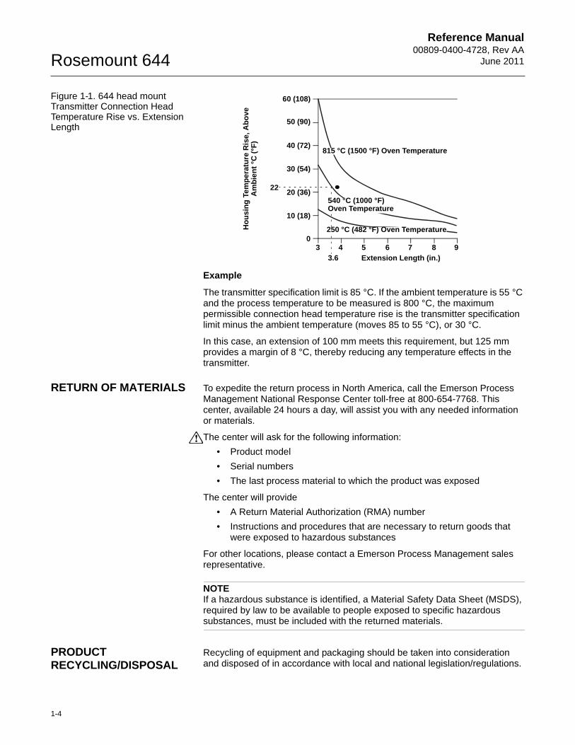
Figure 1-1. 644 head mount Transmitter Connection Head Temperature Rise vs. Extension Length
Example
The transmitter specification limit is 85 °C. If the ambient temperature is 55 °C and the process temperature to be measured is 800 °C, the maximum permissible connection head temperature rise is the transmitter specification limit minus the ambient temperature (moves 85 to 55 °C), or 30 °C.
In this case, an extension of 100 mm meets this requirement, but 125 mm provides a margin of 8 °C, thereby reducing any temperature effects in the transmitter.
RETURN OF MATERIALS To expedite the return process in North America, call the Emerson Process Management National Response Center toll-free at 800-654-7768. This center, available 24 hours a day, will assist you with any needed information or materials.
The center will ask for the following information:
• Product model
• Serial numbers
• The last process material to which the product was exposed
The center will provide
• A Return Material Authorization (RMA) number
• Instructions and procedures that are necessary to return goods that were exposed to hazardous substances
For other locations, please contact a Emerson Process Management sales representative.
NOTEIf a hazardous substance is identified, a Material Safety Data Sheet (MSDS), required by law to be available to people exposed to specific hazardous substances, must be included with the returned materials.
PRODUCT RECYCLING/DISPOSAL
Recycling of equipment and packaging should be taken into consideration and disposed of in accordance with local and national legislation/regulations.
Ho
usi
ng
Te
mp
era
ture
Ris
e, A
bo
ve
Am
bie
nt
°C (
°F)
3 4 5 6 7 8 90
60 (108)
50 (90)
40 (72)
30 (54)
20 (36)
10 (18)
3.6
22
Extension Length (in.)
815 °C (1500 °F) Oven Temperature
540 °C (1000 °F) Oven Temperature
250 °C (482 °F) Oven Temperature
1-4
Reference Manual 00809-0400-4728, Rev AAJune 2011 Rosemount 644
Section 2 Installation
Safety Messages . . . . . . . . . . . . . . . . . . . . . . . . . . . . . . . . . page 2-1Mounting . . . . . . . . . . . . . . . . . . . . . . . . . . . . . . . . . . . . . . . page 2-3Installation . . . . . . . . . . . . . . . . . . . . . . . . . . . . . . . . . . . . . . page 2-4Wiring . . . . . . . . . . . . . . . . . . . . . . . . . . . . . . . . . . . . . . . . . . page 2-7Power Supply . . . . . . . . . . . . . . . . . . . . . . . . . . . . . . . . . . . page 2-11
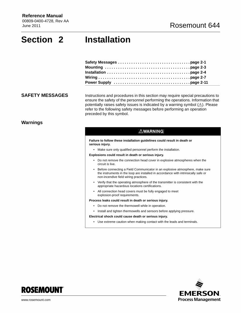
SAFETY MESSAGES Instructions and procedures in this section may require special precautions to ensure the safety of the personnel performing the operations. Information that potentially raises safety issues is indicated by a warning symbol ( ). Please refer to the following safety messages before performing an operation preceded by this symbol.
Warnings
Failure to follow these installation guidelines could result in death orserious injury.
• Make sure only qualified personnel perform the installation.
Explosions could result in death or serious injury.
• Do not remove the connection head cover in explosive atmospheres when the circuit is live.
• Before connecting a Field Communicator in an explosive atmosphere, make sure the instruments in the loop are installed in accordance with intrinsically safe or non-incendive field wiring practices.
• Verify that the operating atmosphere of the transmitter is consistent with the appropriate hazardous locations certifications.
• All connection head covers must be fully engaged to meet explosion-proof requirements.
Process leaks could result in death or serious injury.
• Do not remove the thermowell while in operation.
• Install and tighten thermowells and sensors before applying pressure.
Electrical shock could cause death or serious injury.
• Use extreme caution when making contact with the leads and terminals.
www.rosemount.com
Reference Manual00809-0400-4728, Rev AA
June 2011Rosemount 644
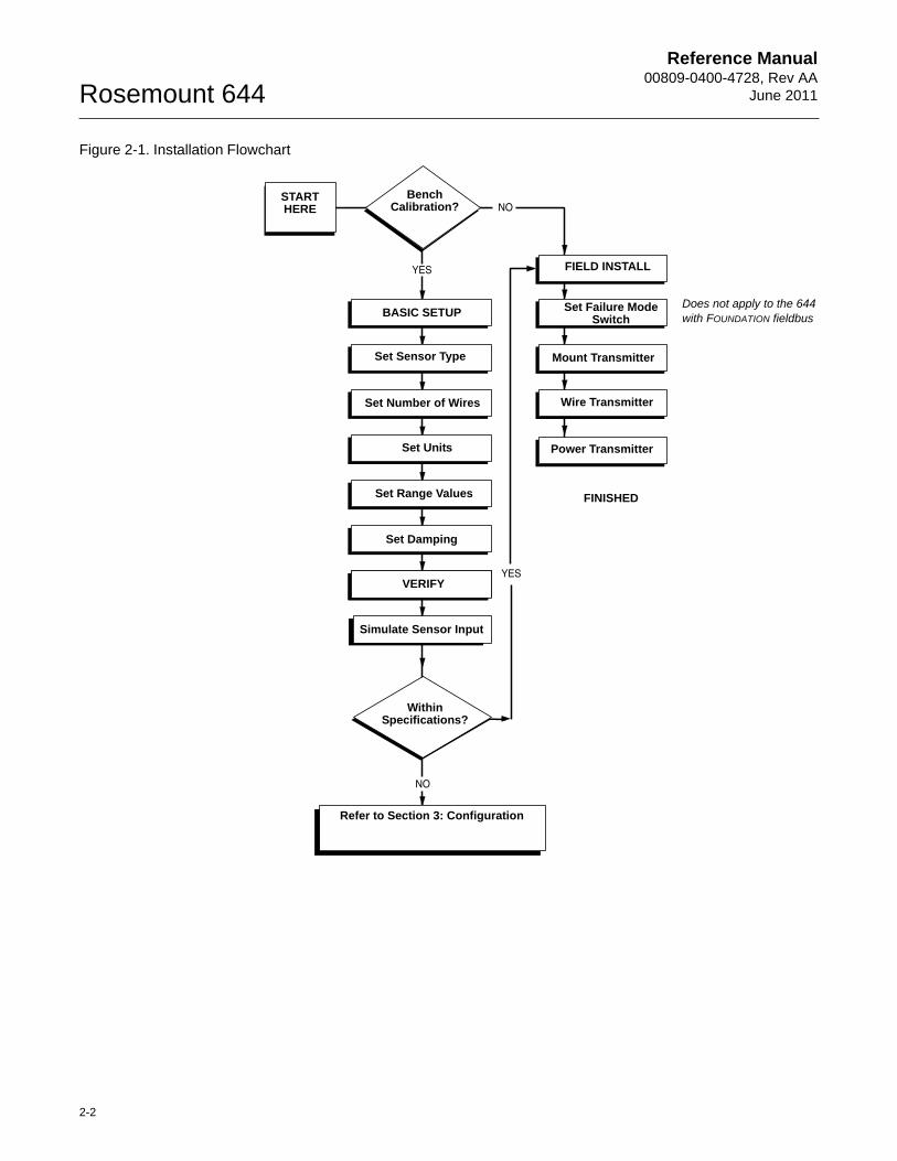
Figure 2-1. Installation Flowchart
START HERE
Bench Calibration?
BASIC SETUP
Set Sensor Type
Set Number of Wires
Set Units
Set Range Values
Set Damping
VERIFY
Simulate Sensor Input
Within Specifications?
Refer to Section 3: Configuration
FIELD INSTALL
Set Failure Mode Switch
Mount Transmitter
Wire Transmitter
Power Transmitter
FINISHED
Does not apply to the 644 with FOUNDATION fieldbus
2-2
Reference Manual 00809-0400-4728, Rev AAJune 2011 Rosemount 644
MOUNTING Mount the transmitter at a high point in the conduit run to prevent moisture from draining into the transmitter housing.
The 644 head mount installs:
• In a connection head or universal head mounted directly on a sensor assembly
• Apart from a sensor assembly using a universal head
• To a DIN rail using an optional mounting clip.
The 644 rail mount attaches directly to a wall or to a DIN rail.
Mounting a 644H to a DIN Rail
To attach a head mount transmitter to a DIN rail, assemble the appropriate rail mounting kit (part number 00644-5301-0010) to the transmitter as shown in Figure 2-2.
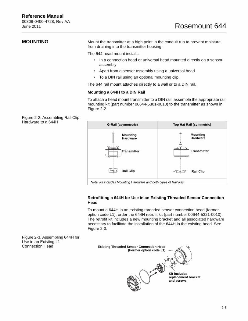
Figure 2-2. Assembling Rail Clip Hardware to a 644H
Retrofitting a 644H for Use in an Existing Threaded Sensor Connection Head
To mount a 644H in an existing threaded sensor connection head (former option code L1), order the 644H retrofit kit (part number 00644-5321-0010). The retrofit kit includes a new mounting bracket and all associated hardware necessary to facilitate the installation of the 644H in the existing head. See Figure 2-3.
Figure 2-3. Assembling 644H for Use in an Existing L1 Connection Head
G-Rail (asymmetric) Top Hat Rail (symmetric)
Note: Kit includes Mounting Hardware and both types of Rail Kits.
Transmitter
Mounting Hardware
Rail Clip
Transmitter
Mounting Hardware
Rail Clip
Kit includes replacement bracket and screws.
Existing Threaded Sensor Connection Head(Former option code L1)
2-3
Reference Manual00809-0400-4728, Rev AA
June 2011Rosemount 644
INSTALLATION
Typical European Installation
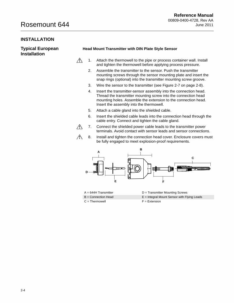
Head Mount Transmitter with DIN Plate Style Sensor
1. Attach the thermowell to the pipe or process container wall. Install and tighten the thermowell before applying process pressure.
2. Assemble the transmitter to the sensor. Push the transmitter mounting screws through the sensor mounting plate and insert the snap rings (optional) into the transmitter mounting screw groove.
3. Wire the sensor to the transmitter (see Figure 2-7 on page 2-8).
4. Insert the transmitter-sensor assembly into the connection head. Thread the transmitter mounting screw into the connection head mounting holes. Assemble the extension to the connection head. Insert the assembly into the thermowell.
5. Attach a cable gland into the shielded cable.
6. Insert the shielded cable leads into the connection head through the cable entry. Connect and tighten the cable gland.
7. Connect the shielded power cable leads to the transmitter power terminals. Avoid contact with sensor leads and sensor connections.
8. Install and tighten the connection head cover. Enclosure covers must be fully engaged to meet explosion-proof requirements.
A = 644H Transmitter D = Transmitter Mounting Screws
B = Connection Head E = Integral Mount Sensor with Flying Leads
C = Thermowell F = Extension
A
D
B
C
E F
2-4
Reference Manual 00809-0400-4728, Rev AAJune 2011 Rosemount 644
Typical North American Installation
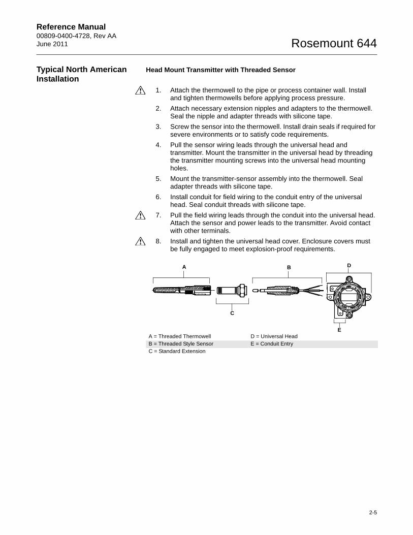
Head Mount Transmitter with Threaded Sensor
1. Attach the thermowell to the pipe or process container wall. Install and tighten thermowells before applying process pressure.
2. Attach necessary extension nipples and adapters to the thermowell. Seal the nipple and adapter threads with silicone tape.
3. Screw the sensor into the thermowell. Install drain seals if required for severe environments or to satisfy code requirements.
4. Pull the sensor wiring leads through the universal head and transmitter. Mount the transmitter in the universal head by threading the transmitter mounting screws into the universal head mounting holes.
5. Mount the transmitter-sensor assembly into the thermowell. Seal adapter threads with silicone tape.
6. Install conduit for field wiring to the conduit entry of the universal head. Seal conduit threads with silicone tape.
7. Pull the field wiring leads through the conduit into the universal head. Attach the sensor and power leads to the transmitter. Avoid contact with other terminals.
8. Install and tighten the universal head cover. Enclosure covers must be fully engaged to meet explosion-proof requirements.
A = Threaded Thermowell D = Universal HeadB = Threaded Style Sensor E = Conduit EntryC = Standard Extension
A B
C
D
E
2-5
Reference Manual00809-0400-4728, Rev AA
June 2011Rosemount 644
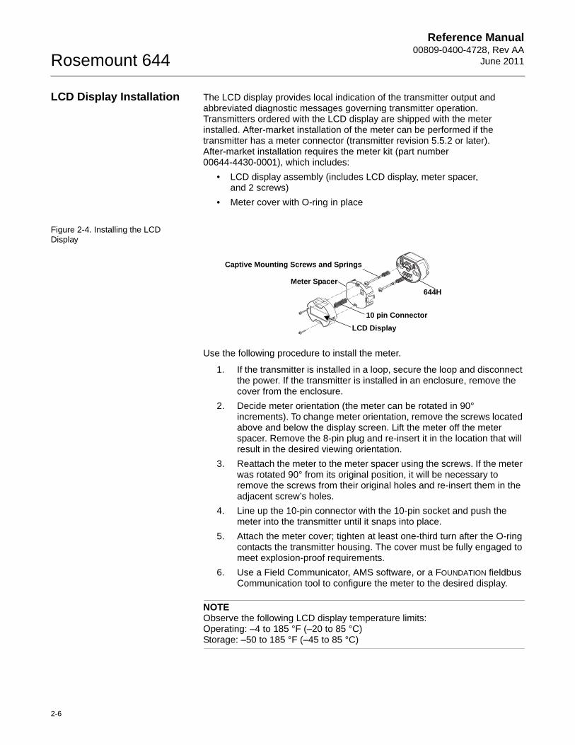
LCD Display Installation The LCD display provides local indication of the transmitter output and abbreviated diagnostic messages governing transmitter operation. Transmitters ordered with the LCD display are shipped with the meter installed. After-market installation of the meter can be performed if the transmitter has a meter connector (transmitter revision 5.5.2 or later). After-market installation requires the meter kit (part number 00644-4430-0001), which includes:
• LCD display assembly (includes LCD display, meter spacer, and 2 screws)
• Meter cover with O-ring in place
Figure 2-4. Installing the LCD Display
Use the following procedure to install the meter.
1. If the transmitter is installed in a loop, secure the loop and disconnect the power. If the transmitter is installed in an enclosure, remove the cover from the enclosure.
2. Decide meter orientation (the meter can be rotated in 90° increments). To change meter orientation, remove the screws located above and below the display screen. Lift the meter off the meter spacer. Remove the 8-pin plug and re-insert it in the location that will result in the desired viewing orientation.
3. Reattach the meter to the meter spacer using the screws. If the meter was rotated 90° from its original position, it will be necessary to remove the screws from their original holes and re-insert them in the adjacent screw’s holes.
4. Line up the 10-pin connector with the 10-pin socket and push the meter into the transmitter until it snaps into place.
5. Attach the meter cover; tighten at least one-third turn after the O-ring contacts the transmitter housing. The cover must be fully engaged to meet explosion-proof requirements.
6. Use a Field Communicator, AMS software, or a FOUNDATION fieldbus Communication tool to configure the meter to the desired display.
NOTEObserve the following LCD display temperature limits:Operating: –4 to 185 °F (–20 to 85 °C)Storage: –50 to 185 °F (–45 to 85 °C)
644H
Captive Mounting Screws and Springs
Meter Spacer
LCD Display
10 pin Connector
2-6
Reference Manual 00809-0400-4728, Rev AAJune 2011 Rosemount 644
WIRING All power to the transmitter is supplied over the signal wiring. Use ordinary copper wire of sufficient size to ensure that the voltage across the transmitter power terminals does not drop below 9 Vdc.
If the sensor is installed in a high-voltage environment and a fault condition or installation error occurs, the sensor leads and transmitter terminals could carry lethal voltages. Use extreme caution when making contact with the leads and terminals.
NOTEDo not apply high voltage (e.g., ac line voltage) to the transmitter terminals. Abnormally high voltage can damage the unit. (Sensor and transmitter power terminals are rated to 42.4 Vdc. A constant 42.4 volts across the sensor terminals may damage the unit.)
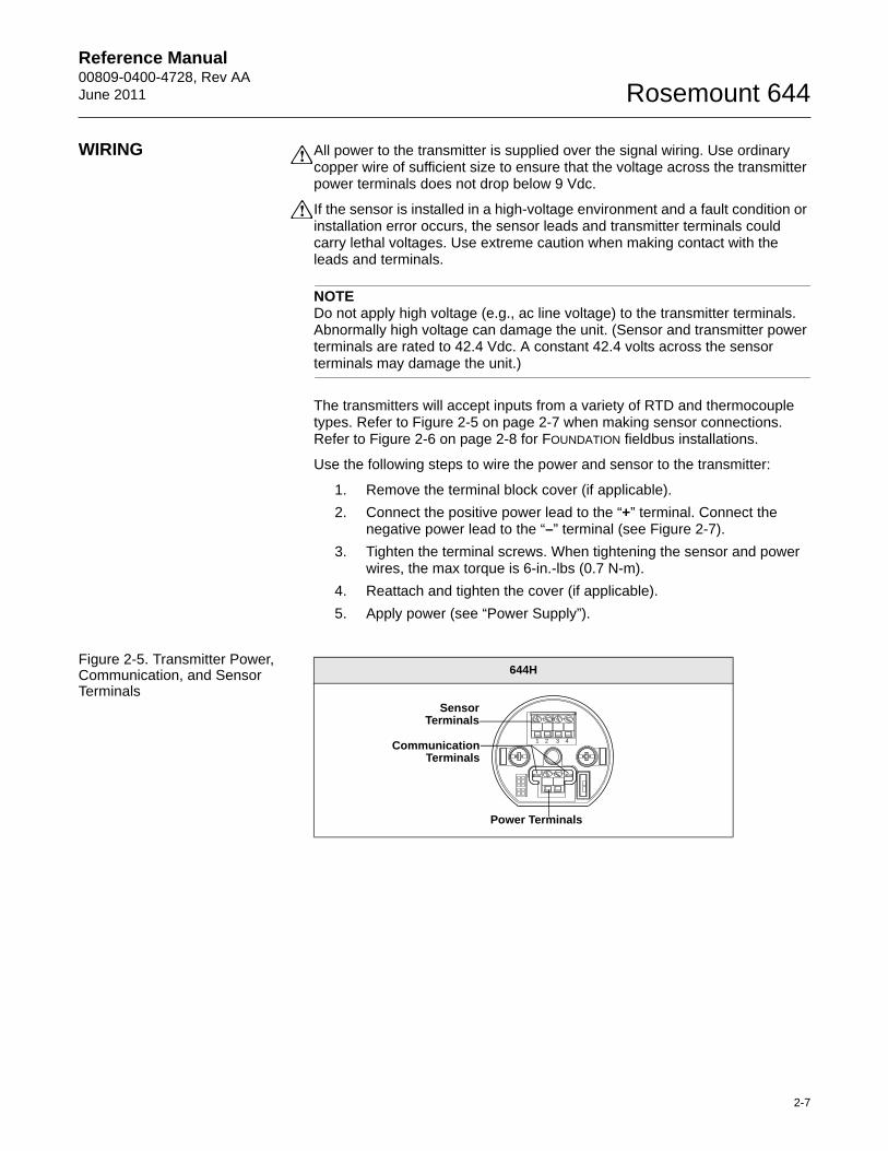
The transmitters will accept inputs from a variety of RTD and thermocouple types. Refer to Figure 2-5 on page 2-7 when making sensor connections. Refer to Figure 2-6 on page 2-8 for FOUNDATION fieldbus installations.
Use the following steps to wire the power and sensor to the transmitter:
1. Remove the terminal block cover (if applicable).
2. Connect the positive power lead to the “+” terminal. Connect the negative power lead to the “–” terminal (see Figure 2-7).
3. Tighten the terminal screws. When tightening the sensor and power wires, the max torque is 6-in.-lbs (0.7 N-m).
4. Reattach and tighten the cover (if applicable).
5. Apply power (see “Power Supply”).
Figure 2-5. Transmitter Power, Communication, and Sensor Terminals
644H
1 2 3 4
SensorTerminals
CommunicationTerminals
Power Terminals
2-7
Reference Manual00809-0400-4728, Rev AA
June 2011Rosemount 644
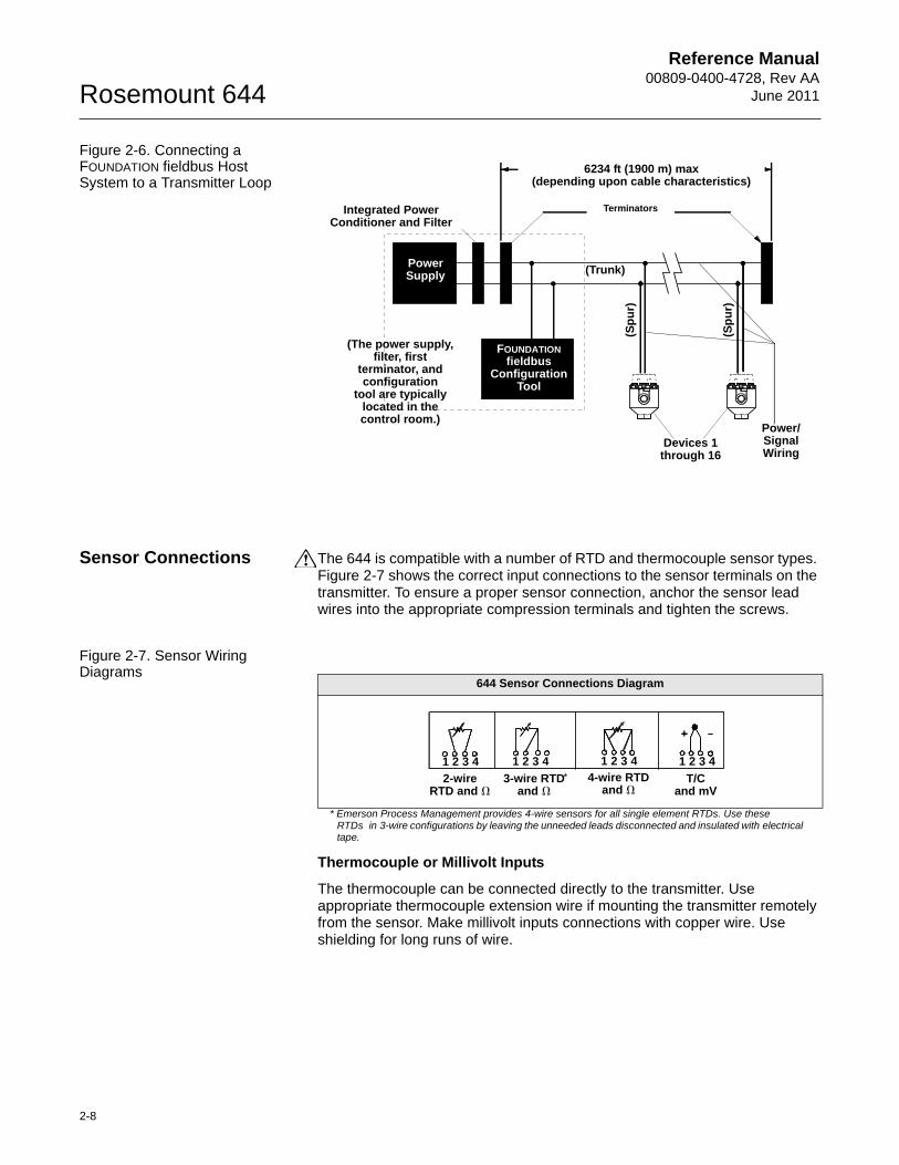
Figure 2-6. Connecting a FOUNDATION fieldbus Host System to a Transmitter Loop
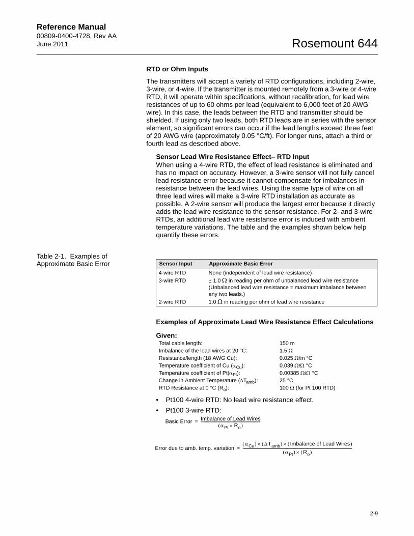
Sensor Connections The 644 is compatible with a number of RTD and thermocouple sensor types. Figure 2-7 shows the correct input connections to the sensor terminals on the transmitter. To ensure a proper sensor connection, anchor the sensor lead wires into the appropriate compression terminals and tighten the screws.
Figure 2-7. Sensor Wiring Diagrams
Thermocouple or Millivolt Inputs
The thermocouple can be connected directly to the transmitter. Use appropriate thermocouple extension wire if mounting the transmitter remotely from the sensor. Make millivolt inputs connections with copper wire. Use shielding for long runs of wire.
Power Supply
6234 ft (1900 m) max(depending upon cable characteristics)
Integrated Power Conditioner and Filter
Terminators
(Sp
ur)
(Sp
ur)
(Trunk)
(The power supply, filter, first
terminator, and configuration
tool are typically located in the control room.)
Devices 1 through 16
FOUNDATION fieldbus
Configuration Tool
Power/Signal Wiring
644 Sensor Connections Diagram
* Emerson Process Management provides 4-wire sensors for all single element RTDs. Use these RTDs in 3-wire configurations by leaving the unneeded leads disconnected and insulated with electrical tape.
2-wire RTD and �
3-wire RTD and �
4-wire RTD and �
T/C and mV
*
1 2 3 4 1 2 3 4 1 2 3 4 1 2 3 4
2-8
Reference Manual 00809-0400-4728, Rev AAJune 2011 Rosemount 644
RTD or Ohm Inputs
The transmitters will accept a variety of RTD configurations, including 2-wire, 3-wire, or 4-wire. If the transmitter is mounted remotely from a 3-wire or 4-wire RTD, it will operate within specifications, without recalibration, for lead wire resistances of up to 60 ohms per lead (equivalent to 6,000 feet of 20 AWG wire). In this case, the leads between the RTD and transmitter should be shielded. If using only two leads, both RTD leads are in series with the sensor element, so significant errors can occur if the lead lengths exceed three feet of 20 AWG wire (approximately 0.05 °C/ft). For longer runs, attach a third or fourth lead as described above.
Sensor Lead Wire Resistance Effect– RTD InputWhen using a 4-wire RTD, the effect of lead resistance is eliminated and has no impact on accuracy. However, a 3-wire sensor will not fully cancel lead resistance error because it cannot compensate for imbalances in resistance between the lead wires. Using the same type of wire on all three lead wires will make a 3-wire RTD installation as accurate as possible. A 2-wire sensor will produce the largest error because it directly adds the lead wire resistance to the sensor resistance. For 2- and 3-wire RTDs, an additional lead wire resistance error is induced with ambient temperature variations. The table and the examples shown below help quantify these errors.
Table 2-1. Examples of Approximate Basic Error
Examples of Approximate Lead Wire Resistance Effect Calculations
Given:
• Pt100 4-wire RTD: No lead wire resistance effect.
• Pt100 3-wire RTD:
Sensor Input Approximate Basic Error
4-wire RTD None (independent of lead wire resistance)
3-wire RTD ± 1.0 in reading per ohm of unbalanced lead wire resistance (Unbalanced lead wire resistance = maximum imbalance between any two leads.)
2-wire RTD 1.0 in reading per ohm of lead wire resistance
Total cable length: 150 m Imbalance of the lead wires at 20 °C: 1.5 Resistance/length (18 AWG Cu): 0.025 /m °CTemperature coefficient of Cu (Cu): 0.039 / °CTemperature coefficient of Pt(Pt): 0.00385 / °CChange in Ambient Temperature (Tamb): 25 °CRTD Resistance at 0 °C (Ro): 100 (for Pt 100 RTD)
Basic Error Imbalance of Lead WiresPt Ro
------------------------------------------------------------------=
Error due to amb. temp. variationCu Tamb Imbalance of Lead Wires
Pt Ro -------------------------------------------------------------------------------------------------------------------------=
2-9
Reference Manual00809-0400-4728, Rev AA
June 2011Rosemount 644
Lead wire imbalance seen by the transmitter = 0.5
• Pt100 2-wire RTD:
Lead wire resistance seen by the transmitter = 150 m × 2 wires × 0.025 /m = 7.5
Basic error 0.5 0.00385 / C 100
---------------------------------------------------------------------------------- 1.3 C= =
Error due to amb. temp. var. of 25 °C
0.0039 / C 25 C 0.5 0.00385 / C 100
------------------------------------------------------------------------------------------------------- 0.1266C==
Basic Error Lead Wire ResistancePt Ro
----------------------------------------------------------=
Error due to amb. temp. variationCu Tamb Lead Wire Resistance
Pt Ro -----------------------------------------------------------------------------------------------------------------=
Basic error 7.5 0.00385 / C 100
---------------------------------------------------------------------------------- 19.5 C= =
Error due to amb. temp. var. of 25 °C
0.0039 / C 25 C 7.5 0.00385 / C 100
------------------------------------------------------------------------------------------------------- 1.9 C==
2-10
Reference Manual 00809-0400-4728, Rev AAJune 2011 Rosemount 644
POWER SUPPLY FOUNDATION fieldbus Installation
Powered over FOUNDATION fieldbus with standard fieldbus power supplies. The transmitter operates between 9.0 and 32.0 Vdc, 11 mA maximum. Transmitter power terminals are rated to 42.4 Vdc.
The power terminals on the 644 with FOUNDATION fieldbus are polarity insensitive.
Ground the Transmitter The transmitter will operate with the current signal loop either floating or grounded. However, the extra noise in floating systems affects many types of readout devices. If the signal appears noisy or erratic, grounding the current signal loop at a single point may solve the problem. The best place to ground the loop is at the negative terminal of the power supply. Do not ground the current signal loop at more than one point.
The transmitter is electrically isolated to 500 Vdc/ac rms (707 Vdc), so the input circuit may also be grounded at any single point. When using a grounded thermocouple, the grounded junction serves as this point.
Neither side of the loop should be grounded on FOUNDATION fieldbus devices. Only the shield wire should be grounded.
NOTEDo not ground the signal wire at both ends.
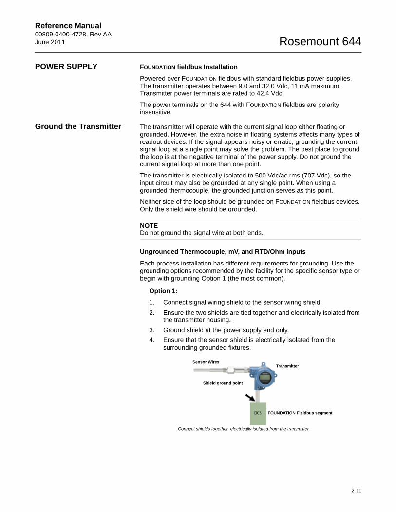
Ungrounded Thermocouple, mV, and RTD/Ohm Inputs
Each process installation has different requirements for grounding. Use the grounding options recommended by the facility for the specific sensor type or begin with grounding Option 1 (the most common).
Option 1:
1. Connect signal wiring shield to the sensor wiring shield.
2. Ensure the two shields are tied together and electrically isolated from the transmitter housing.
3. Ground shield at the power supply end only.
4. Ensure that the sensor shield is electrically isolated from the surrounding grounded fixtures.
Connect shields together, electrically isolated from the transmitter
Shield ground point
FOUNDATION Fieldbus segment
TransmitterSensor Wires
2-11
Reference Manual00809-0400-4728, Rev AA
June 2011Rosemount 644
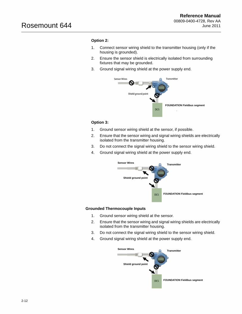
Option 2:
1. Connect sensor wiring shield to the transmitter housing (only if the housing is grounded).
2. Ensure the sensor shield is electrically isolated from surrounding fixtures that may be grounded.
3. Ground signal wiring shield at the power supply end.
Option 3:
1. Ground sensor wiring shield at the sensor, if possible.
2. Ensure that the sensor wiring and signal wiring shields are electrically isolated from the transmitter housing.
3. Do not connect the signal wiring shield to the sensor wiring shield.
4. Ground signal wiring shield at the power supply end.
Grounded Thermocouple Inputs
1. Ground sensor wiring shield at the sensor.
2. Ensure that the sensor wiring and signal wiring shields are electrically isolated from the transmitter housing.
3. Do not connect the signal wiring shield to the sensor wiring shield.
4. Ground signal wiring shield at the power supply end.
Transmitter
Shield ground point
Sensor Wires
FOUNDATION Fieldbus segment
Shield ground point
FOUNDATION Fieldbus segment
TransmitterSensor Wires
Shield ground point
FOUNDATION Fieldbus segment
TransmitterSensor Wires
2-12
Reference Manual 00809-0400-4728, Rev AAJune 2011 Rosemount 644
Section 3 Configuration
Overview . . . . . . . . . . . . . . . . . . . . . . . . . . . . . . . . . . . . . . . page 3-1Safety Messages . . . . . . . . . . . . . . . . . . . . . . . . . . . . . . . . . page 3-1General Block Information . . . . . . . . . . . . . . . . . . . . . . . . . page 3-2FOUNDATION fieldbus function blocks . . . . . . . . . . . . . . . . page 3-4Operation and Maintenance . . . . . . . . . . . . . . . . . . . . . . . . page 3-15
OVERVIEW This section provides information on configuring, troubleshooting, operating, and maintaining the Rosemount 644 Temperature transmitter using FOUNDATION fieldbus protocol.
SAFETY MESSAGES Instructions and procedures in this section may require special precautions to ensure the safety of the personnel performing the operations. Information that potentially raises safety issues is indicated by a warning symbol ( ). Please refer to the following safety messages before performing an operation preceded by this symbol.
Warnings
Failure to follow these installation guidelines could result in death orserious injury.
• Make sure only qualified personnel perform the installation.
Explosions could result in death or serious injury.
• Do not remove the connection head cover in explosive atmospheres when the circuit is live.
• Before powering a FOUNDATION fieldbus segment in an explosive atmosphere, make sure the instruments in the loop are installed in accordance with intrinsically safe or non-incendive field wiring practices.
• Verify that the operating atmosphere of the transmitter is consistent with the appropriate hazardous locations certifications.
• All connection head covers must be fully engaged to meet explosion-proof requirements.
Process leaks could result in death or serious injury.
• Do not remove the thermowell while in operation.
• Install and tighten thermowells and sensors before applying pressure.
Electrical shock could cause death or serious injury.
• Use extreme caution when making contact with the leads and terminals.
www.rosemount.com
Reference Manual00809-0400-4728, Rev AA
June 2011Rosemount 644
GENERAL BLOCK INFORMATION
Device Description Before configuring the device, ensure the host has the appropriate Device Description file revision for this device. The device descriptor can be found on www.rosemount.com. The initial release of the Rosemount 644 with FOUNDATION fieldbus protocol is device revision 1.
Node Address The transmitter is shipped at a temporary (248) address. This will enable FOUNDATION fieldbus host systems to automatically recognize the device and move it to a permanent address.
Modes The Resource, Transducer, and all function blocks in the device have modes of operation. These modes govern the operation of the block. Every block supports both automatic (AUTO) and out of service (OOS) modes. Other modes may also be supported.
Changing Modes
To change the operating mode, set the MODE_BLK.TARGET to the desired mode. After a short delay, the parameter MODE_BLOCK.ACTUAL should reflect the mode change if the block is operating properly.
Permitted Modes
It is possible to prevent unauthorized changes to the operating mode of a block. To do this, configure MODE_BLOCK.PERMITTED to allow only the desired operating modes. It is recommended to always select OOS as one of the permitted modes.
Types of Modes
For the procedures described in this manual, it will be helpful to understand the following modes:
AUTOThe functions performed by the block will execute. If the block has any outputs, these will continue to update. This is typically the normal operating mode.
Out of Service (OOS)The functions performed by the block will not execute. If the block has any outputs, these will typically not update and the status of any values passed to downstream blocks will be “BAD.” To make some changes to the configuration of the block, change the mode of the block to OOS. When the changes are complete, change the mode back to AUTO.
MANIn this mode, variables that are passed out of the block can be manually set for testing or override purposes.
Other Types of ModesOther types of modes are Cas, RCas, ROut, IMan, and LO. Some of these may be supported by different function blocks in the 644. For more information, see the Function Block manual (document number 00809-0100-4783).
3-2
Reference Manual 00809-0400-4728, Rev AAJune 2011 Rosemount 644
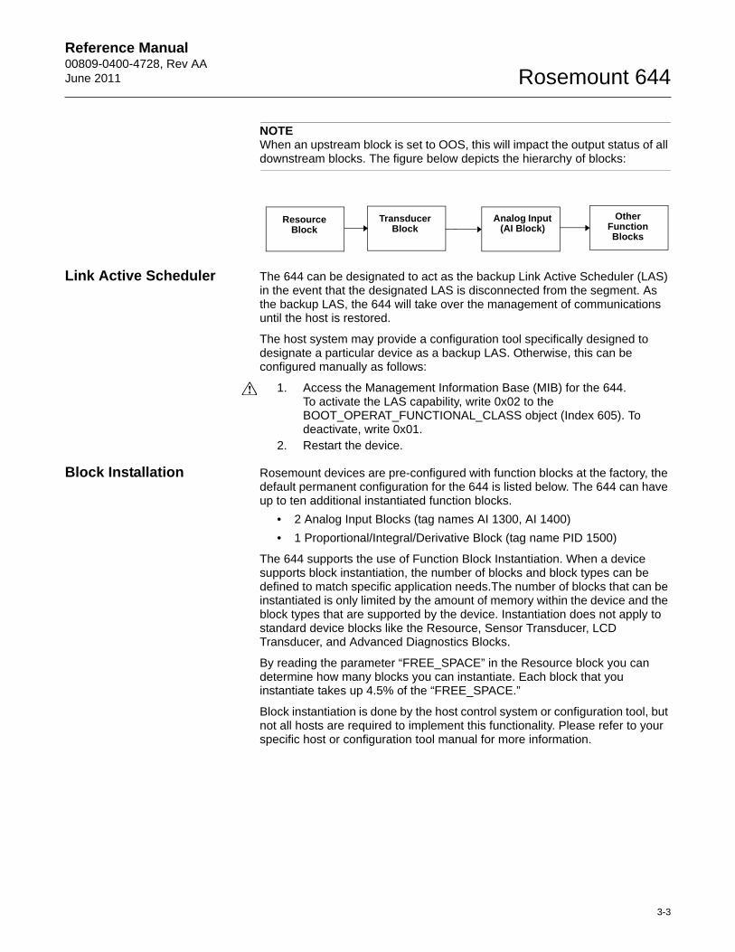
NOTEWhen an upstream block is set to OOS, this will impact the output status of all downstream blocks. The figure below depicts the hierarchy of blocks:
Link Active Scheduler The 644 can be designated to act as the backup Link Active Scheduler (LAS) in the event that the designated LAS is disconnected from the segment. As the backup LAS, the 644 will take over the management of communications until the host is restored.
The host system may provide a configuration tool specifically designed to designate a particular device as a backup LAS. Otherwise, this can be configured manually as follows:
1. Access the Management Information Base (MIB) for the 644.To activate the LAS capability, write 0x02 to the BOOT_OPERAT_FUNCTIONAL_CLASS object (Index 605). To deactivate, write 0x01.
2. Restart the device.
Block Installation Rosemount devices are pre-configured with function blocks at the factory, the default permanent configuration for the 644 is listed below. The 644 can have up to ten additional instantiated function blocks.
• 2 Analog Input Blocks (tag names AI 1300, AI 1400)
• 1 Proportional/Integral/Derivative Block (tag name PID 1500)
The 644 supports the use of Function Block Instantiation. When a device supports block instantiation, the number of blocks and block types can be defined to match specific application needs.The number of blocks that can be instantiated is only limited by the amount of memory within the device and the block types that are supported by the device. Instantiation does not apply to standard device blocks like the Resource, Sensor Transducer, LCD Transducer, and Advanced Diagnostics Blocks.
By reading the parameter “FREE_SPACE” in the Resource block you can determine how many blocks you can instantiate. Each block that you instantiate takes up 4.5% of the “FREE_SPACE.”
Block instantiation is done by the host control system or configuration tool, but not all hosts are required to implement this functionality. Please refer to your specific host or configuration tool manual for more information.
Resource Block
Transducer Block
Analog Input (AI Block)
Other Function Blocks
3-3
Reference Manual00809-0400-4728, Rev AA
June 2011Rosemount 644
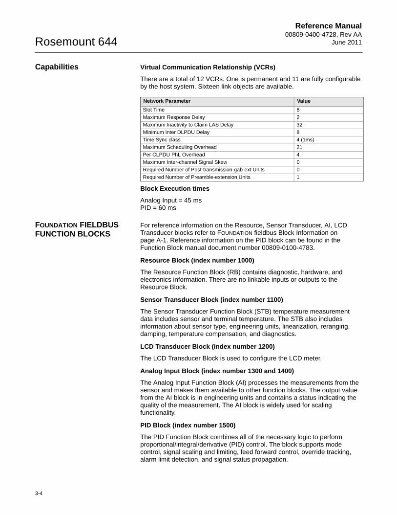
Capabilities Virtual Communication Relationship (VCRs)
There are a total of 12 VCRs. One is permanent and 11 are fully configurable by the host system. Sixteen link objects are available.
Block Execution times
Analog Input = 45 msPID = 60 ms
FOUNDATION FIELDBUS FUNCTION BLOCKS
For reference information on the Resource, Sensor Transducer, AI, LCD Transducer blocks refer to FOUNDATION fieldbus Block Information on page A-1. Reference information on the PID block can be found in the Function Block manual document number 00809-0100-4783.
Resource Block (index number 1000)
The Resource Function Block (RB) contains diagnostic, hardware, and electronics information. There are no linkable inputs or outputs to the Resource Block.
Sensor Transducer Block (index number 1100)
The Sensor Transducer Function Block (STB) temperature measurement data includes sensor and terminal temperature. The STB also includes information about sensor type, engineering units, linearization, reranging, damping, temperature compensation, and diagnostics.
LCD Transducer Block (index number 1200)
The LCD Transducer Block is used to configure the LCD meter.
Analog Input Block (index number 1300 and 1400)
The Analog Input Function Block (AI) processes the measurements from the sensor and makes them available to other function blocks. The output value from the AI block is in engineering units and contains a status indicating the quality of the measurement. The AI block is widely used for scaling functionality.
PID Block (index number 1500)
The PID Function Block combines all of the necessary logic to perform proportional/integral/derivative (PID) control. The block supports mode control, signal scaling and limiting, feed forward control, override tracking, alarm limit detection, and signal status propagation.
Network Parameter Value
Slot Time 8
Maximum Response Delay 2
Maximum Inactivity to Claim LAS Delay 32
Minimum Inter DLPDU Delay 8
Time Sync class 4 (1ms)
Maximum Scheduling Overhead 21
Per CLPDU PhL Overhead 4
Maximum Inter-channel Signal Skew 0
Required Number of Post-transmission-gab-ext Units 0
Required Number of Preamble-extension Units 1
3-4
Reference Manual 00809-0400-4728, Rev AAJune 2011 Rosemount 644
The block supports two forms of the PID equation: Standard and Series. You can choose the appropriate equation using the MATHFORM parameter. The Standard ISA PID equation is the default selection.
Resource Block FEATURES and FEATURES_SEL
The parameters FEATURES and FEATURE_SEL determine optional behavior of the 644.
FEATURESThe FEATURES parameter is read only and defines which features are supported by the 644. Below is a list of the FEATURES the 644 supports.
UNICODEAll configurable string variables in the 644, except tag names, are octet strings. Either ASCII or Unicode may be used. If the configuration device is generating Unicode octet strings, you must set the Unicode option bit.
REPORTSThe 644 supports alert reports. The Reports option bit must be set in the features bit string to use this feature. If it is not set, the host must poll for alerts.
SOFT W LOCK Inputs to the security and write lock functions include the software write lock bits of the FEATURE_SEL parameter, the WRITE_LOCK parameter, and the DEFINE_WRITE_LOCK parameter.
The WRITE_LOCK parameter prevents modification of parameters within the device except to clear the WRITE_LOCK parameter. During this time, the block will function normally updating inputs and outputs and executing algorithms. When the WRITE_LOCK condition is cleared, a WRITE_ALM alert is generated with a priority that corresponds to the WRITE_PRI parameter.
The FEATURE_SEL parameter enables the user to select the software write lock or no write lock capability. In order to enable the software write lock, the SOFT_W_LOCK bit must be set in the FEATURE_SEL parameter. Once this bit is set, the WRITE_LOCK parameter may be set to “Locked” or “Unlocked.” Once the WRITE_LOCK parameter is set to “Locked” by the software, all user requested writes as determined by the DEFINE_WRITE_LOCK parameter shall be rejected.
The DEFINE_WRITE_LOCK parameter allows the user to configure whether the write lock function will control writing to all blocks, or only to the resource and transducer blocks. Internally updated data such as process variables and diagnostics will not be restricted.N/A = No blocks are blockedPhysical = Locks resource and transducer blockEverything = Locks every block.
3-5
Reference Manual00809-0400-4728, Rev AA
June 2011Rosemount 644
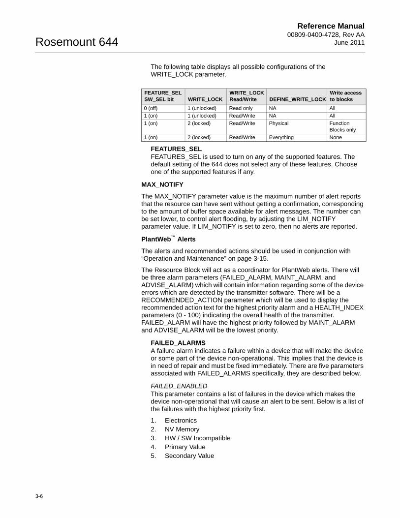
The following table displays all possible configurations of the WRITE_LOCK parameter.
FEATURES_SELFEATURES_SEL is used to turn on any of the supported features. The default setting of the 644 does not select any of these features. Choose one of the supported features if any.
MAX_NOTIFY
The MAX_NOTIFY parameter value is the maximum number of alert reports that the resource can have sent without getting a confirmation, corresponding to the amount of buffer space available for alert messages. The number can be set lower, to control alert flooding, by adjusting the LIM_NOTIFY parameter value. If LIM_NOTIFY is set to zero, then no alerts are reported.
PlantWeb™ Alerts
The alerts and recommended actions should be used in conjunction with “Operation and Maintenance” on page 3-15.
The Resource Block will act as a coordinator for PlantWeb alerts. There will be three alarm parameters (FAILED_ALARM, MAINT_ALARM, and ADVISE_ALARM) which will contain information regarding some of the device errors which are detected by the transmitter software. There will be a RECOMMENDED_ACTION parameter which will be used to display the recommended action text for the highest priority alarm and a HEALTH_INDEX parameters (0 - 100) indicating the overall health of the transmitter. FAILED_ALARM will have the highest priority followed by MAINT_ALARM and ADVISE_ALARM will be the lowest priority.
FAILED_ALARMSA failure alarm indicates a failure within a device that will make the device or some part of the device non-operational. This implies that the device is in need of repair and must be fixed immediately. There are five parameters associated with FAILED_ALARMS specifically, they are described below.
FAILED_ENABLEDThis parameter contains a list of failures in the device which makes the device non-operational that will cause an alert to be sent. Below is a list of the failures with the highest priority first.
1. Electronics2. NV Memory3. HW / SW Incompatible4. Primary Value5. Secondary Value
FEATURE_SEL SW_SEL bit WRITE_LOCK
WRITE_LOCK Read/Write DEFINE_WRITE_LOCK
Write access to blocks
0 (off) 1 (unlocked) Read only NA All
1 (on) 1 (unlocked) Read/Write NA All
1 (on) 2 (locked) Read/Write Physical Function Blocks only
1 (on) 2 (locked) Read/Write Everything None
3-6
Reference Manual 00809-0400-4728, Rev AAJune 2011 Rosemount 644
FAILED_MASKThis parameter will mask any of the failed conditions listed in FAILED_ENABLED. A bit on means that the condition is masked out from alarming and will not be reported.
FAILED_PRIDesignates the alerting priority of the FAILED_ALM, see “Alarm Priority” on page 3-13. The default is 0 and the recommended value are between 8 and 15.
FAILED_ACTIVEThis parameter displays which of the alarms is active. Only the alarm with the highest priority will be displayed. This priority is not the same as the FAILED_PRI parameter described above. This priority is hard coded within the device and is not user configurable.
FAILED_ALMAlarm indicating a failure within a device which makes the device non-operational.
MAINT_ALARMSA maintenance alarm indicates the device or some part of the device needs maintenance soon. If the condition is ignored, the device will eventually fail. There are five parameters associated with MAINT_ALARMS, they are described below.
MAINT_ENABLEDThe MAINT_ENABLED parameter contains a list of conditions indicating the device or some part of the device needs maintenance soon.
Below is a list of the conditions with the highest priority first.
1. Primary Value Degraded2. Secondary Value Degraded3. Diagnostic4. Configuration Error5. Calibration Error
MAINT_MASKThe MAINT_MASK parameter will mask any of the failed conditions listed in MAINT_ENABLED. A bit on means that the condition is masked out from alarming and will not be reported.
MAINT_PRIMAINT_PRI designates the alarming priority of the MAINT_ALM, “Process Alarms” on page 3-12. The default is 0 and the recommended values is 3 to 7.
MAINT_ACTIVEThe MAINT_ACTIVE parameter displays which of the alarms is active. Only the condition with the highest priority will be displayed. This priority is not the same as the MAINT_PRI parameter described above. This priority is hard coded within the device and is not user configurable.
MAINT_ALMAn alarm indicating the device needs maintenance soon. If the condition is ignored, the device will eventually fail.
3-7
Reference Manual00809-0400-4728, Rev AA
June 2011Rosemount 644
Advisory AlarmsAn advisory alarm indicates informative conditions that do not have a direct impact on the device's primary functions. There are five parameters associated with ADVISE_ALARMS. They are described below.
ADVISE_ENABLEDThe ADVISE_ENABLED parameter contains a list of informative conditions that do not have a direct impact on the device's primary functions. Below is a list of the advisories with the highest priority first.
1. NV Writes Deferred2. SPM Process Anomaly detected
ADVISE_MASKThe ADVISE_MASK parameter will mask any of the failed conditions listed in ADVISE_ENABLED. A bit on means the condition is masked out from alarming and will not be reported.
ADVISE_PRIADVISE_PRI designates the alarming priority of the ADVISE_ALM, see “Process Alarms” on page 3-12. The default is 0 and the recommended values are 1 or 2.
ADVISE_ACTIVEThe ADVISE_ACTIVE parameter displays which of the advisories is active. Only the advisory with the highest priority will be displayed. This priority is not the same as the ADVISE_PRI parameter described above. This priority is hard coded within the device and is not user configurable.
ADVISE_ALMADVISE_ALM is an alarm indicating advisory alarms. These conditions do not have a direct impact on the process or device integrity.
Recommended Actions for PlantWeb Alerts
RECOMMENDED_ACTION The RECOMMENDED_ACTION parameter displays a text string that will give a recommended course of action to take based on which type and which specific event of the PlantWeb alerts are active.
3-8
Reference Manual 00809-0400-4728, Rev AAJune 2011 Rosemount 644
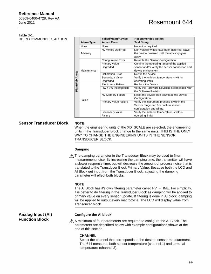
Table 3-1. RB.RECOMMENDED_ACTION
Sensor Transducer Block NOTEWhen the engineering units of the XD_SCALE are selected, the engineering units in the Transducer Block change to the same units. THIS IS THE ONLY WAY TO CHANGE THE ENGINEERING UNITS IN THE SENSOR TRANSDUCER BLOCK.
Damping
The damping parameter in the Transducer Block may be used to filter measurement noise. By increasing the damping time, the transmitter will have a slower response time, but will decrease the amount of process noise that is translated to the Transducer Block Primary Value. Because both the LCD and AI Block get input from the Transducer Block, adjusting the damping parameter will effect both blocks.
NOTEThe AI Block has it's own filtering parameter called PV_FTIME. For simplicity, it is better to do filtering in the Transducer Block as damping will be applied to primary value on every sensor update. If filtering is done in AI block, damping will be applied to output every macrocycle. The LCD will display value from Transducer block.
Analog Input (AI) Function Block
Configure the AI block
A minimum of four parameters are required to configure the AI Block. The parameters are described below with example configurations shown at the end of this section.
CHANNELSelect the channel that corresponds to the desired sensor measurement. The 644 measures both sensor temperature (channel 1) and terminal temperature (channel 2).
Alarm TypeFailed/Maint/AdviseActive Event
Recommended Action Text String
Pla
ntW
eb A
lert
s
None None No action required
AdvisoryNV Writes Deferred Non-volatile writes have been deferred, leave
the device powered until the advisory goes away
Maintenance
Configuration Error Re-write the Sensor ConfigurationPrimary Value Degraded
Confirm the operating range of the applied sensor and/or verify the sensor connection and device environment
Calibration Error Retrim the deviceSecondary Value Degraded
Verify the ambient temperature is within operating limits
Failed
Electronics Failure Replace the DeviceHW / SW Incompatible Verify the Hardware Revision is compatible with
the Software RevisionNV Memory Failure Reset the device then download the Device
ConfigurationPrimary Value Failure Verify the instrument process is within the
Sensor range and / or confirm sensor configuration and wiring.
Secondary Value Failure
Verify the ambient temperature is within operating limits
3-9
Reference Manual00809-0400-4728, Rev AA
June 2011Rosemount 644
L_TYPEThe L_TYPE parameter defines the relationship of the sensor measurement (sensor temperature) to the desired output temperature of the AI Block. The relationship can be direct or indirect.
DirectSelect direct when the desired output will be the same as the sensor measurement (sensor temperature).
IndirectSelect indirect when the desired output is a calculated measurement based on the sensor measurement (e.g. ohm or mV). The relationship between the sensor measurement and the calculated measurement will be linear.
XD_SCALE and OUT_SCALEThe XD_SCALE and OUT_SCALE each include four parameters: 0%, 100%, engineering units, and precision (decimal point). Set these based on the L_TYPE:
L_TYPE is DirectWhen the desired output is the measured variable, set the XD_SCALE to represent the operating range of the process. Set OUT_SCALE to match XD_SCALE.
L_TYPE is IndirectWhen an inferred measurement is made based on the sensor measurement, set the XD_SCALE to represent the operating range that the sensor will see in the process. Determine the inferred measurement values that correspond to the XD_SCALE 0 and 100% points and set these for the OUT_SCALE.
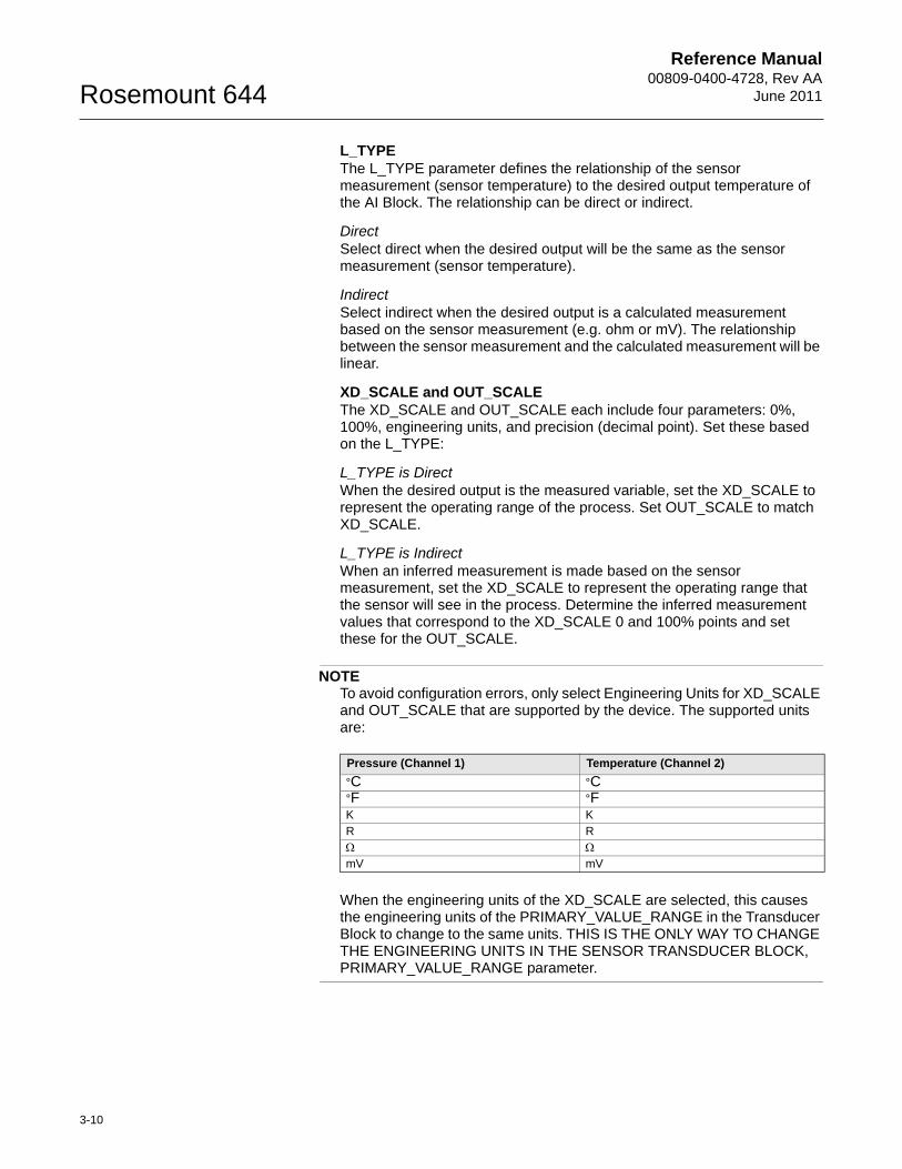
NOTETo avoid configuration errors, only select Engineering Units for XD_SCALE and OUT_SCALE that are supported by the device. The supported units are:
When the engineering units of the XD_SCALE are selected, this causes the engineering units of the PRIMARY_VALUE_RANGE in the Transducer Block to change to the same units. THIS IS THE ONLY WAY TO CHANGE THE ENGINEERING UNITS IN THE SENSOR TRANSDUCER BLOCK, PRIMARY_VALUE_RANGE parameter.
Pressure (Channel 1) Temperature (Channel 2)
°C °C°F °FK KR R mV mV
3-10
Reference Manual 00809-0400-4728, Rev AAJune 2011 Rosemount 644
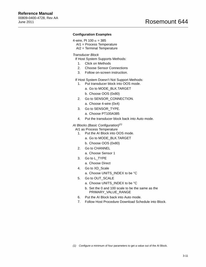
Configuration Examples
4-wire, Pt 100 = 385AI1 = Process TemperatureAI2 = Terminal Temperature
Transducer BlockIf Host System Supports Methods:
1. Click on Methods2. Choose Sensor Connections3. Follow on-screen instruction.
If Host System Doesn’t Not Support Methods:1. Put transducer block into OOS mode.
a. Go to MODE_BLK.TARGET
b. Choose OOS (0x80)
2. Go to SENSOR_CONNECTION.
a. Choose 4-wire (0x4)
3. Go to SENSOR_TYPE.
a. Choose PT100A385
4. Put the transducer block back into Auto mode.
AI Blocks (Basic Configuration)(1)
AI1 as Process Temperature1. Put the AI Block into OOS mode.
a. Go to MODE_BLK.TARGET
b. Choose OOS (0x80)
2. Go to CHANNEL
a. Choose Sensor 1
3. Go to L_TYPE
a. Choose Direct
4. Go to XD_Scale
a. Choose UNITS_INDEX to be °C
5. Go to OUT_SCALE
a. Choose UNITS_INDEX to be °C
b. Set the 0 and 100 scale to be the same as the PRIMARY_VALUE_RANGE
6. Put the AI Block back into Auto mode.7. Follow Host Procedure Download Schedule into Block.
(1) Configure a minimum of four parameters to get a value out of the AI Block.
3-11
Reference Manual00809-0400-4728, Rev AA
June 2011Rosemount 644
AI2 as Terminal Temperature1. Put the AI Block into OOS mode.
a. Go to MODE_BLK.TARGET
b. Choose OOS (0x80)
2. Go to CHANNEL
a. Choose Body Temperature
3. Go to L_TYPE
a. Choose Direct
4. Go to XD_Scale
a. Choose UNITS_INDEX to be °C
5. Go to OUT_SCALE
a. Choose UNITS_INDEX to be °C
b. Set the 0 and 100 scale to be the same as the SECONDARY_VALUE_RANGE
6. Put the AI Block back into Auto mode.7. Follow Host Procedure Download Schedule into Block.
Filtering
The filtering feature changes the response time of the device to smooth variations in output readings caused by rapid changes in input. Adjust the filter time constant (in seconds) using the PV_FTIME parameter. Set the filter time constant to zero to disable the filter feature.
Process Alarms
Process Alarm detection is based on the OUT value. Configure the alarm limits of the following standard alarms:
• High (HI_LIM)
• High high (HI_HI_LIM)
• Low (LO_LIM)
• Low low (LO_LO_LIM)
In order to avoid alarm chattering when the variable is oscillating around the alarm limit, an alarm hysteresis in percent of the PV span can be set using the ALARM_HYS parameter. The priority of each alarm is set in the following parameters:
• HI_PRI
• HI_HI_PRI
• LO_PRI
• LO_LO_PRI
3-12
Reference Manual 00809-0400-4728, Rev AAJune 2011 Rosemount 644
Alarm Priority
Alarms are grouped into five levels of priority:
Status Options
Status Options (STATUS_OPTS) supported by the AI block are shown below:
Propagate Fault ForwardIf the status from the sensor is Bad, Device failure or Bad, Sensor failure, propagate it to OUT without generating an alarm. The use of these sub-status in OUT is determined by this option. Through this option, the user may determine whether alarming (sending of an alert) will be done by the block or propagated downstream for alarming.
Uncertain if LimitedSet the output status of the Analog Input block to uncertain if the measured or calculated value is limited.
BAD if LimitedSet the output status to Bad if the sensor is violating a high or low limit.
Uncertain if Man ModeSet the output status of the Analog Input block to uncertain if the actual mode of the block is Man.
NOTEThe instrument must be in Out of Service mode to set the status option.
Advanced Features
The AI Function Block provides added capability through the addition of the following parameters:
ALARM_TYPE ALARM_TYPE allows one or more of the process alarm conditions detected by the AI function block to be used in setting its OUT_D parameter.
OUT_DOUT_D is the discrete output of the AI function block based on the detection of process alarm condition(s). This parameter may be linked to other function blocks that require a discrete input based on the detected alarm condition.
Priority Number Priority Description
0 The alarm condition is not used.
1 An alarm condition with a priority of 1 is recognized by the system, but is not reported to the operator.
2 An alarm condition with a priority of 2 is reported to the operator.
3-7 Alarm conditions of priority 3 to 7 are advisory alarms of increasing priority.
8-15 Alarm conditions of priority 8 to 15 are critical alarms of increasing priority.
3-13
Reference Manual00809-0400-4728, Rev AA
June 2011Rosemount 644
LCD Transducer Block The LCD meter connects directly to the 644 electronics FOUNDATION fieldbus output board. The meter indicates output and abbreviated diagnostic messages.
The first line of five characters displays the sensor being measured.
If the measurement is in error, “Error” appears on the first line. The second line indicates if the device or the sensor is causing the error.
Each parameter configured for display will appear on the LCD for a brief period before the next parameter is displayed. If the status of the parameter goes bad, the LCD will also cycle diagnostics following the displayed variable.
Custom Meter Configuration
Shipped from the factory, Parameter #1 is configured to display the Primary Variable (temperature) from the LCD Transducer Block. Parameters 2 – 4 are not configured. To change the configuration of Parameter #1 or to configure additional parameters 2 – 4, use the configuration parameters below.
The LCD Transducer Block can be configured to sequence four different process variables as long as the parameters are sourced from a function block that is scheduled to execute within the 644 temperature transmitter. If a function block is scheduled in the 644 that links a process variable from another device on the segment, that process variable can be displayed on the LCD.
DISPLAY_PARAM_SELThe DISPLAY_PARAM_SEL parameter specifies how many process variables will be displayed. Select up to four display parameters.
BLK_TAG_#(1)
Enter the Block Tag of the function block that contains the parameter to be displayed. The default function block tags from the factory are:
TRANSDUCERAI 1300AI 1400PID 1500
BLK_TYPE_#(1)
Enter the Block Type of the function block that contains the parameter to be displayed. This parameter is generally selected via a drop-down menu with a list of possible function block types. (e.g. Transducer, PID, AI, etc.)
PARAM_INDEX_#(1)
The PARAM_INDEX_# parameter is generally selected via a drop-down menu with a list of possible parameter names based upon what is available in the function block type selected. Choose the parameter to be displayed.
CUSTOM_TAG_#(1)
The CUSTOM_TAG_# is an optional user-specified tag identifier that can be configured to be displayed with the parameter in place of the block tag. Enter a tag of up to five characters.
(1) # represents the specified parameter number.
3-14
Reference Manual 00809-0400-4728, Rev AAJune 2011 Rosemount 644
UNITS_TYPE_#(1)
The UNITS_TYPE_# parameter is generally selected via a drop-down menu with three options: AUTO, CUSTOM, or NONE. Select AUTO only when the parameter to be displayed is pressure, temperature, or percent. For other parameters, select CUSTOM and be sure to configure the CUSTOM_UNITS_# parameter. Select NONE if the parameter is to be displayed without associated units.
CUSTOM_UNITS_#(1)
Specify custom units to be displayed with the parameter. Enter up to six characters. To display Custom Units the UNITS_TYPE_# must be set to CUSTOM.
OPERATION AND MAINTENANCE
Overview This section contains information on operation and maintenance procedures.
METHODS AND MANUAL OPERATIONEach FOUNDATION fieldbus host or configuration tool has different ways of displaying and performing operations. Some hosts will use Device Descriptions (DD) and DD Methods to complete device configuration and will display data consistently across platforms. The DD can found on www.rosemount.com. There is no requirement that a host or configuration tool support these features.
The information in this section will describe how to use methods in a general fashion. In addition, if your host or configuration tool does not support methods this section will cover manually configuring the parameters involved with each method operation. For more detailed information on the use of methods, see your host or configuration tool manual.
3-15
Reference Manual00809-0400-4728, Rev AA
June 2011Rosemount 644
Troubleshooting Guides
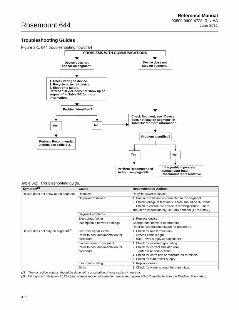
Figure 3-1. 644 troubleshooting flowchart
Table 3-2. Troubleshooting guide.Symptom(1)
(1) The corrective actions should be done with consultation of your system integrator.
Cause Recommended Actions
Device does not show up on segment Unknown Recycle power to deviceNo power to device 1. Ensure the device is connected to the segment.
2. Check voltage at terminals. There should be 9–32Vdc.3. Check to ensure the device is drawing current. There should be approximately 10.5 mA nominal (11 mA max.)
Segment problemsElectronics failing 1. Replace device.Incompatible network settings Change host network parameters.
Refer to host documentation for procedure.Device does not stay on segment(2)
(2) Wiring and installation 31.25 kbit/s, voltage mode, wire medium application guide AG-140 available from the Fieldbus Foundation.
Incorrect signal levels. Refer to host documentation for procedure.
1. Check for two terminators.2. Excess cable length.3. Bad Power supply or conditioner
Excess noise on segment.Refer to host documentation for procedure.
1. Check for incorrect grounding.2. Check for correct shielded wire.3. Tighten wire connections.4. Check for corrosion or moisture on terminals.5. Check for Bad power supply.
Electronics failing 1. Replace device.Other 1. Check for water around the transmitter.
Device does not appear on segment.
Problem Identified?
Yes No
Perform Recommended Action, see Table 3-2.
Check Segment, see “Device does not stay on segment” in Table 3-2 for more information.
Problem Identified?
Yes No
Perform Recommended Action, see page 3-6.
If the problem persists contact your local Rosemount representative.
PROBLEMS WITH COMMUNICATIONS
Device does not stay on segment.
1. Check wiring to device. 2. Recycle power to device.3. Electronic failure.Refer to “Device does not show up on segment” in Table 3-2 for more information.
3-16
Reference Manual 00809-0400-4728, Rev AAJune 2011 Rosemount 644
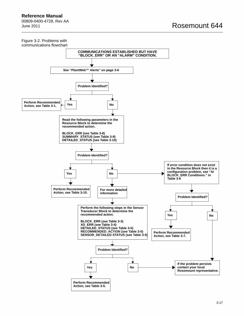
Figure 3-2. Problems with communications flowchart
COMMUNICATIONS ESTABLISHED BUT HAVE “BLOCK_ERR” OR AN “ALARM” CONDITION.
See “PlantWeb™ Alerts” on page 3-6
Read the following parameters in the Resource Block to determine the recommended action.
BLOCK_ERR (see Table 3-8)SUMMARY_STATUS (see Table 3-9)DETAILED_STATUS (see Table 3-10)
Problem Identified?
Yes No
Perform Recommended Action, see Table 3-10.
For more detailed information
Perform the following steps in the Sensor Transducer Block to determine the recommended action.
BLOCK_ERR (see Table 3-3)XD_ERR (see Table 3-4)DETAILED_STATUS (see Table 3-5)RECOMMENDED_ACTION (see Table 3-5)SENSOR_DETAILED STATUS (see Table 3-5)
If error condition does not exist in the Resource Block then it is a configuration problem, see “AI BLOCK_ERR Conditions.” in Table 3-6
Problem Identified?
Yes No
If the problem persists contact your local Rosemount representative.
Problem Identified?
Perform Recommended Action, see Table 3-5.
Yes No
Perform Recommended Action, see Table 3-7.
Yes NoPerform Recommended Action, see Table 3-1.
Problem Identified?
3-17
Reference Manual00809-0400-4728, Rev AA
June 2011Rosemount 644
Sensor Transducer Block Sensor Calibration, Lower and Upper Trim Methods
In order to calibrate the transmitter, run the Lower and Upper Trim Methods. If your system does not support methods, manually configure the Transducer Block parameters listed below.
1. Set MODE_BLK.TARGET to OOS.2. Set SENSOR_CAL_METHOD to User Trim.3. Set CAL_UNIT to supported engineering units in the
Transducer Block. 4. Apply temperature that corresponds to the lower calibration point and
allow the temperature to stabilize. The temperature must be between the range limits defined in PRIMRY_VALUE_RANGE.
5. Set values of CAL_POINT_LO to correspond to the temperature applied by the sensor.
6. Apply temperature, temperature corresponding to the upper calibration.
7. Allow temperature to stabilize.8. Set CAL_POINT_HI.
NOTECAL_POINT_HI must be within PRIMARY_VALUE_RANGE and greater than CAL_POINT_LO + CAL_MIN_SPAN
9. Set SENSOR_CAL_DATE to the current date.10. Set SENSOR_CAL_WHO to the person responsible for the
calibration.11. Set SENSOR _CAL_LOC to the calibration location.12. Set MODE_BLK.TARGET to AUTO.
NOTEIf trim fails, the transmitter will automatically revert to factory trim.
Excessive correction or sensor failure could cause device status to read “calibration error.” To clear this, trim the transmitter.
3-18
Reference Manual 00809-0400-4728, Rev AAJune 2011 Rosemount 644
Recall Factory Trim
To recall a factory trim on the transmitter, run the Recall Factory Trim. If your system does not support methods, manually configure the Transducer Block parameters listed below.
1. Set MODE_BLK.TARGET to OOS.2. Set SENSOR_CAL_METHOD to Factory Trim.3. Set SET_FACTORY_TRIM to Recall.4. Set SENSOR_CAL_DATE to the current date.5. Set SENSOR_CAL_WHO to the person responsible for the
calibration.6. Set SENSOR _CAL_LOC to the calibration location.7. Set MODE_BLK.TARGET to AUTO.
NOTEWhen sensor type is changed, the transmitter reverts to the factory trim. Changing sensor type causes you to loose any trim performed on the transmitter.
Table 3-3. Sensor Transducer Block BLOCK_ERR messages
Table 3-4. Sensor Transducer Block XD_ERR messages
Diagnostics
Table 3-5 lists the potential errors and the possible corrective actions for the given values. The corrective actions are in order of increasing system level compromises. The first step should always be to reset the transmitter and then if the error persists, try the steps in Table 3-5. Start with the first corrective action and then try the second.
Condition Name and Description
Other
Out of Service: The actual mode is out of service.
Condition Name and Description
Electronics Failure: An electrical component failed.
I/O Failure: An I/O failure occurred.
Software Error: The software has detected an internal error.
Calibration Error: An error occurred during calibration of the device.
Algorithm Error: The algorithm used in the transducer block produced an error due to overflow, data reasonableness failure, etc.
3-19
Reference Manual00809-0400-4728, Rev AA
June 2011Rosemount 644
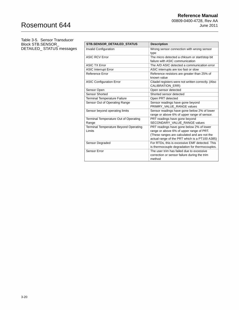
Table 3-5. Sensor Transducer Block STB.SENSOR_DETAILED_ STATUS messages
STB.SENSOR_DETAILED_STATUS Description
Invalid Configuration Wrong sensor connection with wrong sensor type
ASIC RCV Error The micro detected a chksum or start/stop bit failure with ASIC communication
ASIC TX Error The A/D ASIC detected a communication errorASIC Interrupt Error ASIC interrupts are too fast or slowReference Error Reference resistors are greater than 25% of
known valueASIC Configuration Error Citadel registers were not written correctly. (Also
CALIBRATION_ERR)Sensor Open Open sensor detectedSensor Shorted Shorted sensor detectedTerminal Temperature Failure Open PRT detectedSensor Out of Operating Range Sensor readings have gone beyond
PRIMRY_VALUE_RANGE valuesSensor beyond operating limits Sensor readings have gone below 2% of lower
range or above 6% of upper range of sensor.Terminal Temperature Out of Operating Range
PRT readings have gone beyond SECONDARY_VALUE_RANGE values
Terminal Temperature Beyond Operating Limits
PRT readings have gone below 2% of lower range or above 6% of upper range of PRT. (These ranges are calculated and are not the actual range of the PRT which is a PT100 A385)
Sensor Degraded For RTDs, this is excessive EMF detected. This is thermocouple degradation for thermocouples.
Sensor Error The user trim has failed due to excessive correction or sensor failure during the trim method
3-20
Reference Manual 00809-0400-4728, Rev AAJune 2011 Rosemount 644
Analog Input (AI) Function Block
Status
Along with the measured or calculated PV value, every FOUNDATION fieldbus block passes an additional parameter called STATUS. The PV and STATUS are passed from the Transducer Block to the Analog Input Block. The STATUS can be one of the following: GOOD, BAD, or UNCERTAIN. When there are no problems detected by the self-diagnostics of the block, the STATUS will be GOOD. If a problem occurs with the hardware in the device or the quality of the process variable is compromised for some reason, the STATUS will become either BAD or UNCERTAIN depending upon the nature of the problem. It is important that the Control Strategy that makes use of the Analog Input Block is configured to monitor the STATUS and take action where appropriate when the STATUS is no longer GOOD.
Simulation
Simulate replaces the channel value coming from the Sensor Transducer Block. For testing purposes, it is possible to manually drive the output of the Analog Input Block to a desired value. There are two ways to do this.
Manual ModeTo change only the OUT_VALUE and not the OUT_STATUS of the AI Block, place the TARGET MODE of the block to MANUAL. Then, change the OUT_VALUE to the desired value.
Simulate
1. If the SIMULATE switch is in the OFF position, move it to the ON position. If the SIMULATE jumper is already in the ON position, you must move it to off and place it back in the ON position.
NOTEAs a safety measure, the switch must be reset every time power is interrupted to the device in order to enable SIMULATE. This prevents a device that is tested on the bench from getting installed in the process with SIMULATE still active.
2. To change both the OUT_VALUE and OUT_STATUS of the AI Block, set the TARGET MODE to AUTO.
3. Set SIMULATE_ENABLE_DISABLE to ‘Active.’ 4. Enter the desired SIMULATE_VALUE to change the OUT_VALUE
and SIMULATE_STATUS_QUALITY to change the OUT_STATUS.If errors occur when performing the above steps, be sure that the SIMULATE jumper has been reset after powering up the device.
3-21
Reference Manual00809-0400-4728, Rev AA
June 2011Rosemount 644
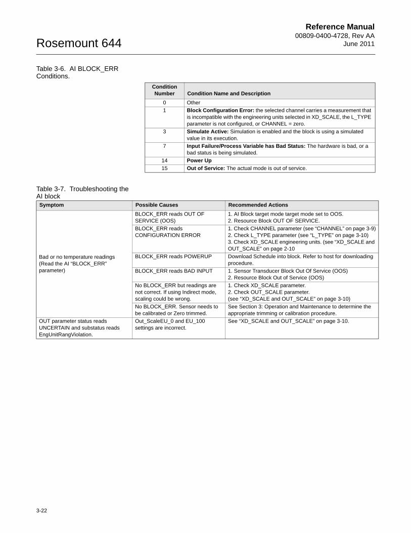
Table 3-6. AI BLOCK_ERR Conditions.
Table 3-7. Troubleshooting the AI block
Condition Number Condition Name and Description
0 Other
1 Block Configuration Error: the selected channel carries a measurement that is incompatible with the engineering units selected in XD_SCALE, the L_TYPE parameter is not configured, or CHANNEL = zero.
3 Simulate Active: Simulation is enabled and the block is using a simulated value in its execution.
7 Input Failure/Process Variable has Bad Status: The hardware is bad, or a bad status is being simulated.
14 Power Up
15 Out of Service: The actual mode is out of service.
Symptom Possible Causes Recommended Actions
Bad or no temperature readings(Read the AI “BLOCK_ERR” parameter)
BLOCK_ERR reads OUT OF SERVICE (OOS)
1. AI Block target mode target mode set to OOS.2. Resource Block OUT OF SERVICE.
BLOCK_ERR reads CONFIGURATION ERROR
1. Check CHANNEL parameter (see “CHANNEL” on page 3-9)2. Check L_TYPE parameter (see “L_TYPE” on page 3-10)3. Check XD_SCALE engineering units. (see “XD_SCALE and OUT_SCALE” on page 2-10
BLOCK_ERR reads POWERUP Download Schedule into block. Refer to host for downloading procedure.
BLOCK_ERR reads BAD INPUT 1. Sensor Transducer Block Out Of Service (OOS)2. Resource Block Out of Service (OOS)
No BLOCK_ERR but readings are not correct. If using Indirect mode, scaling could be wrong.
1. Check XD_SCALE parameter.2. Check OUT_SCALE parameter. (see “XD_SCALE and OUT_SCALE” on page 3-10)
No BLOCK_ERR. Sensor needs to be calibrated or Zero trimmed.
See Section 3: Operation and Maintenance to determine the appropriate trimming or calibration procedure.
OUT parameter status reads UNCERTAIN and substatus reads EngUnitRangViolation.
Out_ScaleEU_0 and EU_100 settings are incorrect.
See “XD_SCALE and OUT_SCALE” on page 3-10.
3-22
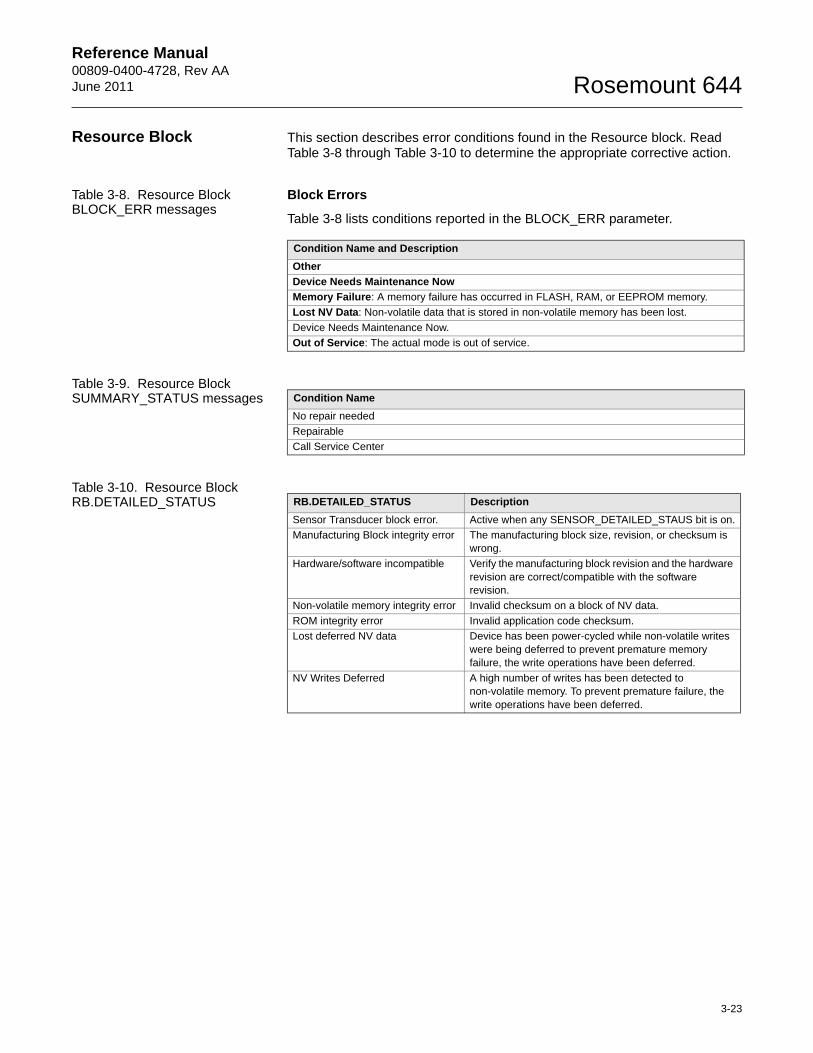
Reference Manual 00809-0400-4728, Rev AAJune 2011 Rosemount 644
Resource Block This section describes error conditions found in the Resource block. Read Table 3-8 through Table 3-10 to determine the appropriate corrective action.
Table 3-8. Resource Block BLOCK_ERR messages
Block Errors
Table 3-8 lists conditions reported in the BLOCK_ERR parameter.
Table 3-9. Resource Block SUMMARY_STATUS messages
Table 3-10. Resource Block RB.DETAILED_STATUS
Condition Name and Description
Other
Device Needs Maintenance Now
Memory Failure: A memory failure has occurred in FLASH, RAM, or EEPROM memory.
Lost NV Data: Non-volatile data that is stored in non-volatile memory has been lost.
Device Needs Maintenance Now.
Out of Service: The actual mode is out of service.
Condition Name
No repair needed
Repairable
Call Service Center
RB.DETAILED_STATUS Description
Sensor Transducer block error. Active when any SENSOR_DETAILED_STAUS bit is on.
Manufacturing Block integrity error The manufacturing block size, revision, or checksum is wrong.
Hardware/software incompatible Verify the manufacturing block revision and the hardware revision are correct/compatible with the software revision.
Non-volatile memory integrity error Invalid checksum on a block of NV data.
ROM integrity error Invalid application code checksum.
Lost deferred NV data Device has been power-cycled while non-volatile writes were being deferred to prevent premature memory failure, the write operations have been deferred.
NV Writes Deferred A high number of writes has been detected to non-volatile memory. To prevent premature failure, the write operations have been deferred.
3-23
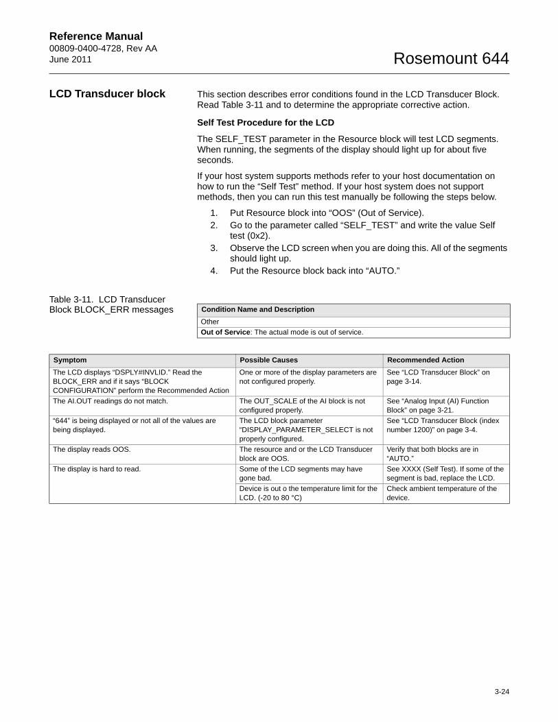
Reference Manual 00809-0400-4728, Rev AAJune 2011 Rosemount 644
LCD Transducer block This section describes error conditions found in the LCD Transducer Block. Read Table 3-11 and to determine the appropriate corrective action.
Self Test Procedure for the LCD
The SELF_TEST parameter in the Resource block will test LCD segments. When running, the segments of the display should light up for about five seconds.
If your host system supports methods refer to your host documentation on how to run the “Self Test” method. If your host system does not support methods, then you can run this test manually be following the steps below.
1. Put Resource block into “OOS” (Out of Service).2. Go to the parameter called “SELF_TEST” and write the value Self
test (0x2).3. Observe the LCD screen when you are doing this. All of the segments
should light up.4. Put the Resource block back into “AUTO.”
Table 3-11. LCD Transducer Block BLOCK_ERR messages Condition Name and Description
Other
Out of Service: The actual mode is out of service.
Symptom Possible Causes Recommended Action
The LCD displays “DSPLY#INVLID.” Read the BLOCK_ERR and if it says “BLOCK CONFIGURATION” perform the Recommended Action
One or more of the display parameters are not configured properly.
See “LCD Transducer Block” on page 3-14.
The AI.OUT readings do not match. The OUT_SCALE of the AI block is not configured properly.
See “Analog Input (AI) Function Block” on page 3-21.
“644” is being displayed or not all of the values are being displayed.
The LCD block parameter “DISPLAY_PARAMETER_SELECT is not properly configured.
See “LCD Transducer Block (index number 1200)” on page 3-4.
The display reads OOS. The resource and or the LCD Transducer block are OOS.
Verify that both blocks are in “AUTO.”
The display is hard to read. Some of the LCD segments may have gone bad.
See XXXX (Self Test). If some of the segment is bad, replace the LCD.
Device is out o the temperature limit for the LCD. (-20 to 80 °C)
Check ambient temperature of the device.
3-24
Reference Manual 00809-0400-4728, Rev AAJune 2011 Rosemount 644
Appendix A Specifications and Reference Data
Specifications . . . . . . . . . . . . . . . . . . . . . . . . . . . . . . . . . . . page A-1Foundation Fieldbus Specifications . . . . . . . . . . . . . . . . . page A-4Accuracy . . . . . . . . . . . . . . . . . . . . . . . . . . . . . . . . . . . . . . . page A-6Dimensional Drawings . . . . . . . . . . . . . . . . . . . . . . . . . . . . page A-9Ordering Information . . . . . . . . . . . . . . . . . . . . . . . . . . . . . page A-12 . . . . . . . . . . . . . . . . . . . . . . . . . . . . . . . . . . . . . . . . . . . . . . . page A-17SPECIFICATIONS
Functional InputsUser-selectable; sensor terminals rated to 42.4 Vdc. See “Accuracy” on page A-6 for sensor options.
OutputSingle 2-wired device with a completely digital output with FOUNDATION fieldbus communication (ITK 5.1 compliant).
IsolationInput/output isolation tested to 500 Vdc/ac rms (707 Vdc) at 50/60 Hz
Local Display The optional five-digit integral LCD Display includes a floating or fixed decimal point. It can also display engineering units (°F, °C, °R, K, , and millivolts), milliampere, and percent of span. The display can be configured to alternate between selected display options. Display settings are preconfigured at the factory according to the standard transmitter configuration. They can be reconfigured in the field using FOUNDATION fieldbus communications.
Humidity Limits0–99% relative humidity
Update Time 0.5 seconds
Accuracy (default configuration) PT 100
FOUNDATION fieldbus: ±0.15 °C
www.rosemount.com
Reference Manual00809-0400-4728, Rev AA
June 2011Rosemount 644
Physical Electrical Connections
Field Communicator Connections
Materials of Construction
Materials of Constructions (Stainless Steel Housing for Biotechnology, Pharmaceutical Industries, and Sanitary Applications)Housing and Standard Meter Cover
• 316 SST
Cover O-Ring
• Buna-N
MountingThe 644R attaches directly to a wall or a DIN rail. The 644H installs in a connection head or universal head mounted directly on a sensor assembly, apart from a sensor assembly using a universal head, or to a DIN rail using an optional mounting clip.
Weight
Weight (Stainless Steel Housing for Biotechnology, Pharmaceutical Industries, and Sanitary Applications)
Enclosure Ratings (644H)All option codes (S1, S2, S3, S4, J5 and J6, J7 and J8) are NEMA 4X, IP66, and IP68. Option code J6 is CSA Enclosure Type 4X.
Sanitary Housing SurfaceSurface finish is polished to 32 RMA. Laser etched product marking on housing and standard covers.
Model Power and Sensor Terminals
644H Compression screws permanently fixed to terminal block
WAGO® Spring clamp terminals are optional (option code G5)
Communication Terminals
644H Clips permanently fixed to terminal block
Electronics Housing and Terminal Block
644H Noryl® glass reinforced
Enclosure (Option code J5 or J6)
Housing Low-copper aluminum
Paint Polyurethane
Cover O-ring Buna-N
Code Options Weight
644H Head Mount Transmitter 92 g (3.25 oz)M5 LCD Display 38 g (1.34 oz)J5, J6 Universal Head, Standard Cover 577 g (20.35 oz)J5, J6 Universal Head, Meter Cover 667 g (23.53 oz)
Option Code Standard Cover Meter Cover
S1 840 g (27 oz) 995 g (32 oz)
S2 840 g (27 oz) 995 g (32 oz)
S3 840 g (27 oz) 995 g (32 oz)
S4 840 g (27 oz) 995 g (32 oz)
A-2
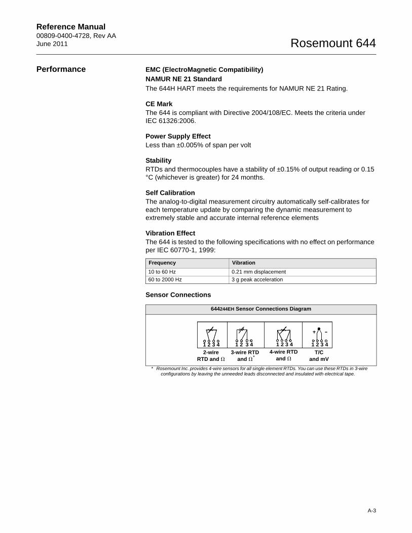
Reference Manual 00809-0400-4728, Rev AAJune 2011 Rosemount 644
A-3
Performance EMC (ElectroMagnetic Compatibility)
NAMUR NE 21 Standard
The 644H HART meets the requirements for NAMUR NE 21 Rating.
CE MarkThe 644 is compliant with Directive 2004/108/EC. Meets the criteria under IEC 61326:2006.
Power Supply EffectLess than ±0.005% of span per volt
StabilityRTDs and thermocouples have a stability of ±0.15% of output reading or 0.15 °C (whichever is greater) for 24 months.
Self CalibrationThe analog-to-digital measurement circuitry automatically self-calibrates for each temperature update by comparing the dynamic measurement to extremely stable and accurate internal reference elements
Vibration EffectThe 644 is tested to the following specifications with no effect on performance per IEC 60770-1, 1999:
Sensor Connections
Frequency Vibration
10 to 60 Hz 0.21 mm displacement
60 to 2000 Hz 3 g peak acceleration
644244EH Sensor Connections Diagram
* Rosemount Inc. provides 4-wire sensors for all single element RTDs. You can use these RTDs in 3-wire configurations by leaving the unneeded leads disconnected and insulated with electrical tape.
2-wire RTD and �
3-wire RTD and �
4-wire RTD and �
T/C and mV*
1 2 3 4 1 2 3 4 1 2 3 4 1 2 3 4
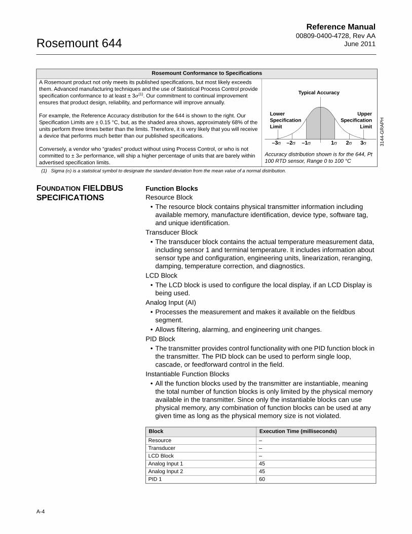
Reference Manual00809-0400-4728, Rev AA
June 2011Rosemount 644
31
44
-GR
AP
H
FOUNDATION FIELDBUS SPECIFICATIONS
Function BlocksResource Block
• The resource block contains physical transmitter information including available memory, manufacture identification, device type, software tag, and unique identification.
Transducer Block
• The transducer block contains the actual temperature measurement data, including sensor 1 and terminal temperature. It includes information about sensor type and configuration, engineering units, linearization, reranging, damping, temperature correction, and diagnostics.
LCD Block
• The LCD block is used to configure the local display, if an LCD Display is being used.
Analog Input (AI)
• Processes the measurement and makes it available on the fieldbus segment.
• Allows filtering, alarming, and engineering unit changes.
PID Block
• The transmitter provides control functionality with one PID function block in the transmitter. The PID block can be used to perform single loop, cascade, or feedforward control in the field.
Instantiable Function Blocks
• All the function blocks used by the transmitter are instantiable, meaning the total number of function blocks is only limited by the physical memory available in the transmitter. Since only the instantiable blocks can use physical memory, any combination of function blocks can be used at any given time as long as the physical memory size is not violated.
Rosemount Conformance to Specifications
A Rosemount product not only meets its published specifications, but most likely exceeds them. Advanced manufacturing techniques and the use of Statistical Process Control provide specification conformance to at least ± 3�(1). Our commitment to continual improvement ensures that product design, reliability, and performance will improve annually.
For example, the Reference Accuracy distribution for the 644 is shown to the right. Our Specification Limits are ± 0.15 °C, but, as the shaded area shows, approximately 68% of the units perform three times better than the limits. Therefore, it is very likely that you will receive a device that performs much better than our published specifications.
Conversely, a vendor who “grades” product without using Process Control, or who is not committed to ± 3� performance, will ship a higher percentage of units that are barely within advertised specification limits.
Accuracy distribution shown is for the 644, Pt 100 RTD sensor, Range 0 to 100 °C
(1) Sigma () is a statistical symbol to designate the standard deviation from the mean value of a normal distribution.
Lower Specification Limit
UpperSpecification
Limit
Typical Accuracy
–3 –2 –1 1 2 3
Block Execution Time (milliseconds)
Resource –
Transducer –
LCD Block –
Analog Input 1 45
Analog Input 2 45
PID 1 60
A-4
Reference Manual 00809-0400-4728, Rev AAJune 2011 Rosemount 644
Turn-on TimePerformance within specifications in less than 20 seconds after power is applied, when damping value is set to 0 seconds.
StatusIf self-diagnostics detect a sensor burnout or a transmitter failure, the status of the measurement will be updated accordingly. Status may also send the PID output to a safe value.
Power Supply Powered over FOUNDATION fieldbus with standard fieldbus power supplies. The transmitter operates between 9.0 and 32.0 Vdc, 11 mA maximum. The power terminals are rated to 42.4 Vdc max.
AlarmsThe AI function block allows the user to configure the alarms to HI-HI, HI, LO, or LO-LO with a variety of priority levels and hysteresis settings.
Backup Link Active Scheduler (LAS)The transmitter is classified as a device link master, which means it can function as a Link Active Scheduler (LAS) if the current link master device fails or is removed from the segment.
The host or other configuration tool is used to download the schedule for the application to the link master device. In the absence of a primary link master, the transmitter will claim the LAS and provide permanent control for the H1 segment.
FOUNDATION fieldbus Parameters
Software Upgrade in the FieldSoftware for the 644 with FOUNDATION fieldbus will be easy to upgrade in the field. Users will be able to take advantage of software enhancements by loading new application software into the device memory.
Schedule Entries 25(1)
(1) Minimum quantity.
Links 16(1)
Virtual Communications Relationships (VCR) 12(1)
A-5
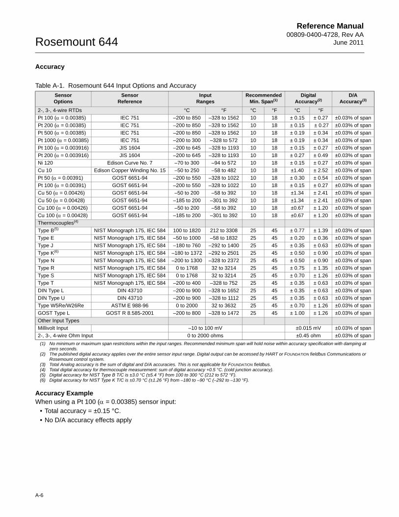
Reference Manual00809-0400-4728, Rev AA
June 2011Rosemount 644
Accuracy
Accuracy Example When using a Pt 100 ( = 0.00385) sensor input:
• Total accuracy = ±0.15 °C.
• No D/A accuracy effects apply
Table A-1. Rosemount 644 Input Options and Accuracy
Sensor Options
Sensor Reference
Input Ranges
Recommended Min. Span(1)
Digital Accuracy(2)
D/A Accuracy(3)
2-, 3-, 4-wire RTDs °C °F °C °F °C °F
Pt 100 ( = 0.00385) IEC 751 –200 to 850 –328 to 1562 10 18 ± 0.15 ± 0.27 ±0.03% of span
Pt 200 ( = 0.00385) IEC 751 –200 to 850 –328 to 1562 10 18 ± 0.15 ± 0.27 ±0.03% of span
Pt 500 ( = 0.00385) IEC 751 –200 to 850 –328 to 1562 10 18 ± 0.19 ± 0.34 ±0.03% of span
Pt 1000 ( = 0.00385) IEC 751 –200 to 300 –328 to 572 10 18 ± 0.19 ± 0.34 ±0.03% of span
Pt 100 ( = 0.003916) JIS 1604 –200 to 645 –328 to 1193 10 18 ± 0.15 ± 0.27 ±0.03% of span
Pt 200 ( = 0.003916) JIS 1604 –200 to 645 –328 to 1193 10 18 ± 0.27 ± 0.49 ±0.03% of span
Ni 120 Edison Curve No. 7 –70 to 300 –94 to 572 10 18 ± 0.15 ± 0.27 ±0.03% of span
Cu 10 Edison Copper Winding No. 15 –50 to 250 –58 to 482 10 18 ±1.40 ± 2.52 ±0.03% of span
Pt 50 ( = 0.00391) GOST 6651-94 –200 to 550 –328 to 1022 10 18 ± 0.30 ± 0.54 ±0.03% of span
Pt 100 ( = 0.00391) GOST 6651-94 –200 to 550 –328 to 1022 10 18 ± 0.15 ± 0.27 ±0.03% of span
Cu 50 ( = 0.00426) GOST 6651-94 –50 to 200 –58 to 392 10 18 ±1.34 ± 2.41 ±0.03% of span
Cu 50 ( = 0.00428) GOST 6651-94 –185 to 200 –301 to 392 10 18 ±1.34 ± 2.41 ±0.03% of span
Cu 100 ( = 0.00426) GOST 6651-94 –50 to 200 –58 to 392 10 18 ±0.67 ± 1.20 ±0.03% of span
Cu 100 ( = 0.00428) GOST 6651-94 –185 to 200 –301 to 392 10 18 ±0.67 ± 1.20 ±0.03% of span
Thermocouples(4)
Type B(5) NIST Monograph 175, IEC 584 100 to 1820 212 to 3308 25 45 ± 0.77 ± 1.39 ±0.03% of span
Type E NIST Monograph 175, IEC 584 –50 to 1000 –58 to 1832 25 45 ± 0.20 ± 0.36 ±0.03% of span
Type J NIST Monograph 175, IEC 584 –180 to 760 –292 to 1400 25 45 ± 0.35 ± 0.63 ±0.03% of span
Type K(6) NIST Monograph 175, IEC 584 –180 to 1372 –292 to 2501 25 45 ± 0.50 ± 0.90 ±0.03% of span
Type N NIST Monograph 175, IEC 584 –200 to 1300 –328 to 2372 25 45 ± 0.50 ± 0.90 ±0.03% of span
Type R NIST Monograph 175, IEC 584 0 to 1768 32 to 3214 25 45 ± 0.75 ± 1.35 ±0.03% of span
Type S NIST Monograph 175, IEC 584 0 to 1768 32 to 3214 25 45 ± 0.70 ± 1.26 ±0.03% of span
Type T NIST Monograph 175, IEC 584 –200 to 400 –328 to 752 25 45 ± 0.35 ± 0.63 ±0.03% of span
DIN Type L DIN 43710 –200 to 900 –328 to 1652 25 45 ± 0.35 ± 0.63 ±0.03% of span
DIN Type U DIN 43710 –200 to 900 –328 to 1112 25 45 ± 0.35 ± 0.63 ±0.03% of span
Type W5Re/W26Re ASTM E 988-96 0 to 2000 32 to 3632 25 45 ± 0.70 ± 1.26 ±0.03% of span
GOST Type L GOST R 8.585-2001 –200 to 800 –328 to 1472 25 45 ± 1.00 ± 1.26 ±0.03% of span
Other Input Types
Millivolt Input –10 to 100 mV ±0.015 mV ±0.03% of span
2-, 3-, 4-wire Ohm Input 0 to 2000 ohms ±0.45 ohm ±0.03% of span
(1) No minimum or maximum span restrictions within the input ranges. Recommended minimum span will hold noise within accuracy specification with damping at zero seconds.
(2) The published digital accuracy applies over the entire sensor input range. Digital output can be accessed by HART or FOUNDATION fieldbus Communications or Rosemount control system.
(3) Total Analog accuracy is the sum of digital and D/A accuracies. This is not applicable for FOUNDATION fieldbus.(4) Total digital accuracy for thermocouple measurement: sum of digital accuracy +0.5 °C. (cold junction accuracy).(5) Digital accuracy for NIST Type B T/C is ±3.0 °C (±5.4 °F) from 100 to 300 °C (212 to 572 °F).(6) Digital accuracy for NIST Type K T/C is ±0.70 °C (±1.26 °F) from –180 to –90 °C (–292 to –130 °F).
A-6
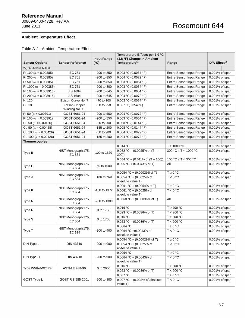
Reference Manual 00809-0400-4728, Rev AAJune 2011 Rosemount 644
an
an
an
an
an
an
an
an
an
an
an
an
an
an
an
an
an
an
an
an
an
an
an
an
an
an
an
an
an
an
an
an
an
an
an
an
an
Ambient Temperature Effect
Table A-2. Ambient Temperature Effect
Sensor Options Sensor ReferenceInput Range (°C)
Temperature Effects per 1.0 °C (1.8 °F) Change in Ambient Temperature(1) Range D/A Effect(2)
2-, 3-, 4-wire RTDs
Pt 100 ( = 0.00385) IEC 751 -200 to 850 0.003 °C (0.0054 °F) Entire Sensor Input Range 0.001% of sp
Pt 200 ( = 0.00385) IEC 751 -200 to 850 0.004 °C (0.0072 °F) Entire Sensor Input Range 0.001% of sp
Pt 500 ( = 0.00385) IEC 751 -200 to 850 0.003 °C (0.0054 °F) Entire Sensor Input Range 0.001% of sp
Pt 1000 ( = 0.00385) IEC 751 -200 to 300 0.003 °C (0.0054 °F) Entire Sensor Input Range 0.001% of sp
Pt 100 ( = 0.003916) JIS 1604 -200 to 645 0.003 °C (0.0054 °F) Entire Sensor Input Range 0.001% of sp
Pt 200 ( = 0.003916) JIS 1604 -200 to 645 0.004 °C (0.0072 °F) Entire Sensor Input Range 0.001% of sp
Ni 120 Edison Curve No. 7 -70 to 300 0.003 °C (0.0054 °F) Entire Sensor Input Range 0.001% of sp
Cu 10 Edison Copper Winding No. 15
-50 to 250 0.03 °C (0.054 °F) Entire Sensor Input Range 0.001% of sp
Pt 50 ( = 0.00391) GOST 6651-94 -200 to 550 0.004 °C (0.0072 °F) Entire Sensor Input Range 0.001% of sp
Pt 100 ( = 0.00391) GOST 6651-94 -200 to 550 0.003 °C (0.0054 °F) Entire Sensor Input Range 0.001% of sp
Cu 50 ( = 0.00426) GOST 6651-94 -50 to 200 0.008 °C (0.0144 °F) Entire Sensor Input Range 0.001% of sp
Cu 50 ( = 0.00428) GOST 6651-94 -185 to 200 0.008 °C (0.0144 °F) Entire Sensor Input Range 0.001% of sp
Cu 100 ( = 0.00426) GOST 6651-94 -50 to 200 0.004 °C (0.0072 °F) Entire Sensor Input Range 0.001% of sp
Cu 100 ( = 0.00428) GOST 6651-94 -185 to 200 0.004 °C (0.0072 °F) Entire Sensor Input Range 0.001% of sp
Thermocouples
Type BNIST Monograph 175,
IEC 584100 to 1820
0.014 °C T 1000 °C 0.001% of sp
0.032 °C – (0.0025% of (T – 300))
300 °C T < 1000 °C 0.001% of sp
0.054 °C – (0.011% of (T – 100)) 100 °C T < 300 °C 0.001% of sp
Type ENIST Monograph 175,
IEC 584-50 to 1000
0.005 °C + (0.0043% of T) All 0.001% of sp
Type JNIST Monograph 175,
IEC 584-180 to 760
0.0054 °C + (0.00029%of T) T 0 °C 0.001% of sp
0.0054 °C + (0.0025% of absolute value T)
T < 0 °C 0.001% of sp
Type KNIST Monograph 175,
IEC 584-180 to 1372
0.0061 °C + (0.0054% of T) T 0 °C 0.001% of sp
0.0061 °C + (0.0025% of absolute value T)
T < 0 °C 0.001% of sp
Type NNIST Monograph 175,
IEC 584-200 to 1300
0.0068 °C + (0.00036% of T) All 0.001% of sp
Type RNIST Monograph 175,
IEC 5840 to 1768
0.016 °C T 200 °C 0.001% of sp
0.023 °C – (0.0036% of T) T < 200 °C 0.001% of sp
Type SNIST Monograph 175,
IEC 5840 to 1768
0.016 °C T 200 °C 0.001% of sp
0.023 °C – (0.0036% of T) T < 200 °C 0.001% of sp
Type TNIST Monograph 175,
IEC 584-200 to 400
0.0064 °C T 0 °C 0.001% of sp
0.0064 °C +(0.0043% of absolute value T)
T < 0 °C 0.001% of sp
DIN Type L DIN 43710 -200 to 9000.0054 °C + (0.00029% of T) T 0 °C 0.001% of sp
0.0054 °C + (0.0025% of absolute value T)
T < 0 °C 0.001% of sp
DIN Type U DIN 43710 -200 to 9000.0064 °C T 0 °C 0.001% of sp
0.0064 °C + (0.0043% of absolute value T)
T < 0 °C 0.001% of sp
Type W5Re/W26Re ASTM E 988-96 0 to 20000.016 °C T 200 °C 0.001% of sp
0.023 °C – (0.0036% of T) T < 200 °C 0.001% of sp
GOST Type L GOST R 8.585-2001 -200 to 8000.007 °C T 0 °C 0.001% of sp
0.007 °C – (0.003% of absolute value T)
T < 0 °C 0.001% of sp
A-7
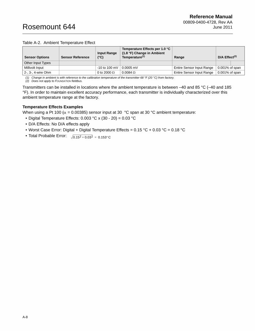
Reference Manual00809-0400-4728, Rev AA
June 2011Rosemount 644
an
an
Transmitters can be installed in locations where the ambient temperature is between –40 and 85 °C (–40 and 185 °F). In order to maintain excellent accuracy performance, each transmitter is individually characterized over this ambient temperature range at the factory.
Temperature Effects Examples When using a Pt 100 ( = 0.00385) sensor input at 30 °C span at 30 °C ambient temperature:
• Digital Temperature Effects: 0.003 °C x (30 - 20) = 0.03 °C
• D/A Effects: No D/A effects apply
• Worst Case Error: Digital + Digital Temperature Effects = 0.15 °C + 0.03 °C = 0.18 °C
• Total Probable Error:
Other Input Types
Millivolt Input -10 to 100 mV 0.0005 mV Entire Sensor Input Range 0.001% of sp
2-, 3-, 4-wire Ohm 0 to 2000 0.0084 Entire Sensor Input Range 0.001% of sp
(1) Change in ambient is with reference to the calibration temperature of the transmitter 68 °F (20 °C) from factory.(2) Does not apply to FOUNDATION fieldbus.
Table A-2. Ambient Temperature Effect
Sensor Options Sensor ReferenceInput Range (°C)
Temperature Effects per 1.0 °C (1.8 °F) Change in Ambient Temperature(1) Range D/A Effect(2)
0.152 0.032+ 0.153C=
A-8
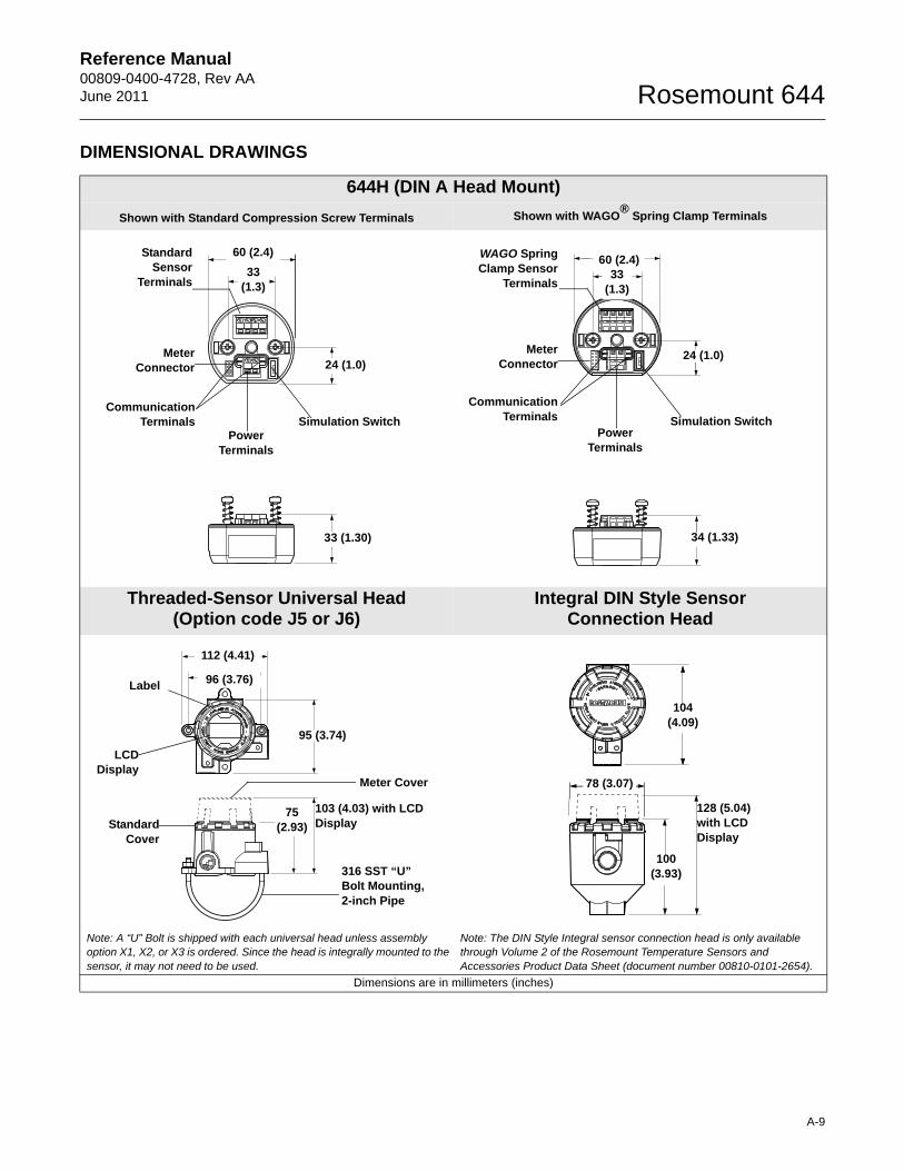
Reference Manual 00809-0400-4728, Rev AAJune 2011 Rosemount 644
DIMENSIONAL DRAWINGS
644H (DIN A Head Mount)
Shown with Standard Compression Screw Terminals Shown with WAGO®
Spring Clamp Terminals
Threaded-Sensor Universal Head (Option code J5 or J6)
Integral DIN Style Sensor Connection Head
Note: A “U” Bolt is shipped with each universal head unless assembly option X1, X2, or X3 is ordered. Since the head is integrally mounted to the sensor, it may not need to be used.
Note: The DIN Style Integral sensor connection head is only available through Volume 2 of the Rosemount Temperature Sensors and Accessories Product Data Sheet (document number 00810-0101-2654).
Dimensions are in millimeters (inches)
Simulation Switch
StandardSensor
Terminals
CommunicationTerminals
60 (2.4)
33 (1.3)
Power Terminals
33 (1.30)
24 (1.0)Meter
Connector
33 (1.3)
60 (2.4)
34 (1.33)
WAGO SpringClamp Sensor
Terminals
24 (1.0)
CommunicationTerminals Simulation Switch
MeterConnector
Power Terminals
95 (3.74)
96 (3.76)
112 (4.41)
Meter Cover
316 SST “U” Bolt Mounting, 2-inch Pipe
75 (2.93)
Label
StandardCover
LCDDisplay
103 (4.03) with LCD Display
78 (3.07)
128 (5.04) with LCD Display
100 (3.93)
104 (4.09)
A-9
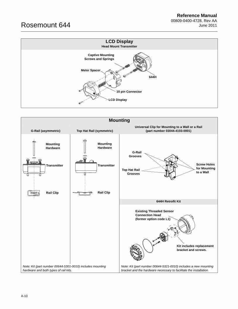
Reference Manual00809-0400-4728, Rev AA
June 2011Rosemount 644
LCD DisplayHead Mount Transmitter
644H
Captive MountingScrews and Springs
Meter Spacer
LCD Display
10 pin Connector
Mounting
G-Rail (asymmetric) Top Hat Rail (symmetric)Universal Clip for Mounting to a Wall or a Rail
(part number 03044-4103-0001)
644H Retrofit Kit
Note: Kit (part number 00644-5301-0010) includes mounting hardware and both types of rail kits.
Note: Kit (part number 00644-5321-0010) includes a new mounting bracket and the hardware necessary to facilitate the installation.
Transmitter
Mounting Hardware
Rail Clip
Transmitter
Mounting Hardware
Rail Clip
G-RailGrooves
Top Hat RailGrooves
Screw Holes for Mounting to a Wall
Kit includes replacement bracket and screws.
Existing Threaded Sensor Connection Head (former option code L1)
A-10
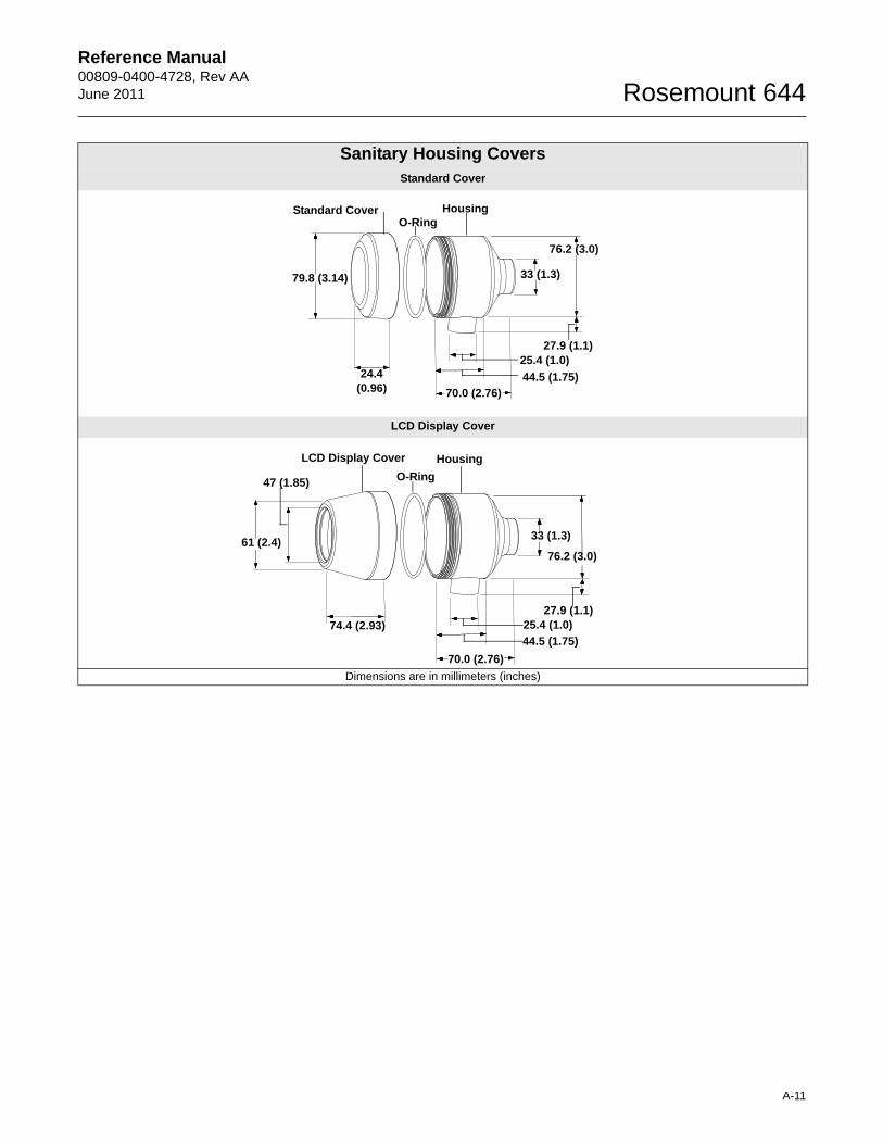
Reference Manual 00809-0400-4728, Rev AAJune 2011 Rosemount 644
Sanitary Housing CoversStandard Cover
LCD Display Cover
Dimensions are in millimeters (inches)
79.8 (3.14)
70.0 (2.76)
33 (1.3)
76.2 (3.0)
24.4 (0.96)
25.4 (1.0)
44.5 (1.75)
27.9 (1.1)
Standard Cover HousingO-Ring
70.0 (2.76)
33 (1.3)
76.2 (3.0)
47 (1.85)
61 (2.4)
25.4 (1.0)
44.5 (1.75)
27.9 (1.1)74.4 (2.93)
LCD Display Cover Housing
O-Ring
A-11
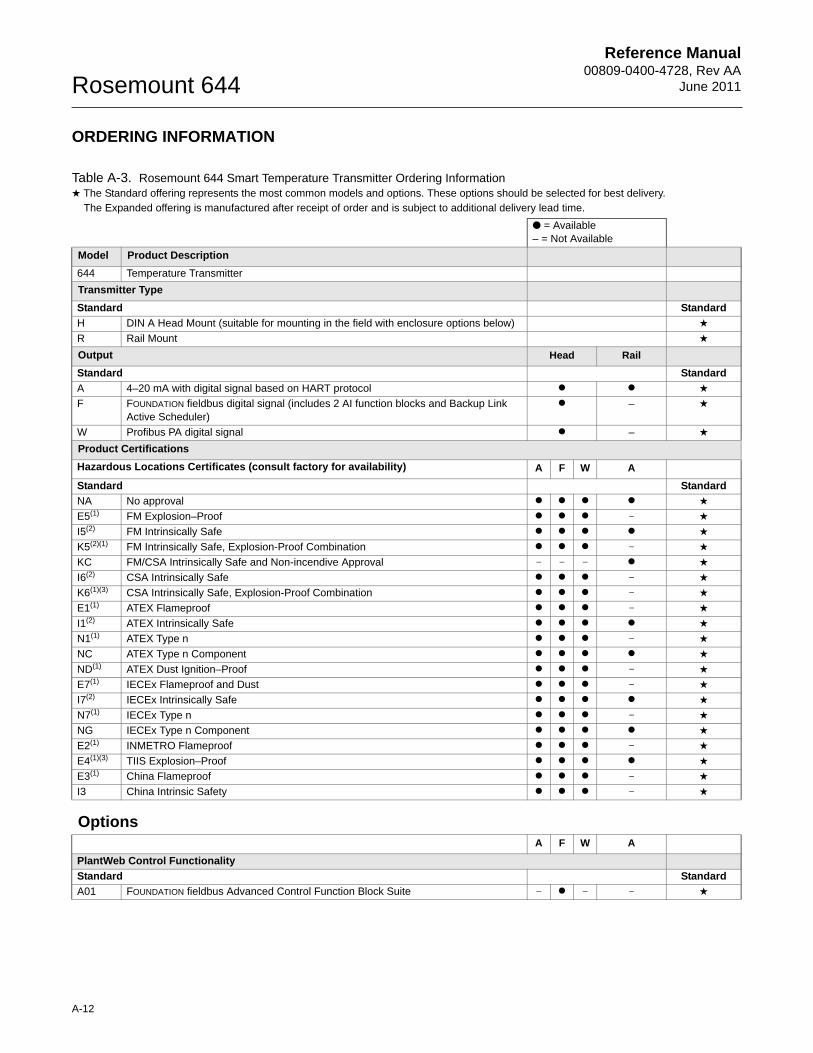
Reference Manual00809-0400-4728, Rev AA
June 2011Rosemount 644
ORDERING INFORMATION
Table A-3. Rosemount 644 Smart Temperature Transmitter Ordering Information★ The Standard offering represents the most common models and options. These options should be selected for best delivery.__The Expanded offering is manufactured after receipt of order and is subject to additional delivery lead time.
● = Available– = Not Available
Model Product Description
644 Temperature Transmitter
Transmitter Type
Standard Standard
H DIN A Head Mount (suitable for mounting in the field with enclosure options below) ★
R Rail Mount ★
Output Head Rail
Standard Standard
A 4–20 mA with digital signal based on HART protocol ● ● ★
F FOUNDATION fieldbus digital signal (includes 2 AI function blocks and Backup Link Active Scheduler)
● – ★
W Profibus PA digital signal ● – ★
Product Certifications
Hazardous Locations Certificates (consult factory for availability) A F W A
Standard Standard
NA No approval ● ● ● ● ★
E5(1) FM Explosion–Proof ● ● ● – ★
I5(2) FM Intrinsically Safe ● ● ● ● ★
K5(2)(1) FM Intrinsically Safe, Explosion-Proof Combination ● ● ● – ★
KC FM/CSA Intrinsically Safe and Non-incendive Approval – – – ● ★
I6(2) CSA Intrinsically Safe ● ● ● – ★
K6(1)(3) CSA Intrinsically Safe, Explosion-Proof Combination ● ● ● – ★
E1(1) ATEX Flameproof ● ● ● – ★
I1(2) ATEX Intrinsically Safe ● ● ● ● ★
N1(1) ATEX Type n ● ● ● – ★
NC ATEX Type n Component ● ● ● ● ★
ND(1) ATEX Dust Ignition–Proof ● ● ● – ★
E7(1) IECEx Flameproof and Dust ● ● ● – ★
I7(2) IECEx Intrinsically Safe ● ● ● ● ★
N7(1) IECEx Type n ● ● ● – ★
NG IECEx Type n Component ● ● ● ● ★
E2(1) INMETRO Flameproof ● ● ● – ★
E4(1)(3) TIIS Explosion–Proof ● ● ● ● ★
E3(1) China Flameproof ● ● ● – ★
I3 China Intrinsic Safety ● ● ● – ★
OptionsA F W A
PlantWeb Control Functionality
Standard Standard
A01 FOUNDATION fieldbus Advanced Control Function Block Suite – ● – – ★
A-12
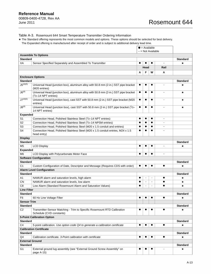
Reference Manual 00809-0400-4728, Rev AAJune 2011 Rosemount 644
Assemble To Options
Standard Standard
XA Sensor Specified Separately and Assembled To Transmitter ● ● ● – ★
Head Rail
A F W A
Enclosure Options
Standard Standard
J5(4)(5) Universal Head (junction box), aluminum alloy with 50.8 mm (2-in.) SST pipe bracket (M20 entries)
● ● ● – ★
J6(4) Universal Head (junction box), aluminum alloy with 50.8 mm (2-in.) SST pipe bracket (1/2–14 NPT entries)
● ● ● – ★
J7(4)(5) Universal Head (junction box), cast SST with 50.8 mm (2-in.) SST pipe bracket (M20 entries)
● ● ● – ★
J8(4) Universal Head (junction box), cast SST with 50.8 mm (2-in.) SST pipe bracket (1/2–14 NPT entries)
● ● ● – ★
Expanded
S1 Connection Head, Polished Stainless Steel (1/2–14 NPT entries) ● ● ● –
S2 Connection Head, Polished Stainless Steel (1/2–14 NPSM entries) ● ● ● –
S3 Connection Head, Polished Stainless Steel (M20 x 1.5 conduit and entries) ● ● ● –
S4 Connection Head, Polished Stainless Steel (M20 x 1.5 conduit entries, M24 x 1.5 head entry)
● ● ● –
Display
Standard Standard
M5 LCD Display ● ● ● – ★
Expanded
M6 LCD Display with Polycarbonate Meter Face ● ● ● –
Software Configuration
Standard Standard
C1 Custom Configuration of Date, Descriptor and Message (Requires CDS with order) ● ● ● ● ★
Alarm Level Configuration
Standard Standard
A1 NAMUR alarm and saturation levels, high alarm ● – – ● ★
CN NAMUR alarm and saturation levels, low alarm ● – – ● ★
C8 Low Alarm (Standard Rosemount Alarm and Saturation Values) ● – – ● ★
Line Filter
Standard Standard
F6 60 Hz Line Voltage Filter ● ● ● ● ★
Sensor Trim
Standard Standard
C2 Transmitter-Sensor Matching - Trim to Specific Rosemount RTD Calibration Schedule (CVD constants)
● ● ● ● ★
5-Point Calibration Option
Standard Standard
C4 5-point calibration. Use option code Q4 to generate a calibration certificate ● ● ● ● ★
Calibration Certificate
Standard Standard
Q4 Calibration certificate. 3-Point calibration with certificate ● ● ● ● ★
External Ground
Standard Standard
G1 External ground lug assembly (see “External Ground Screw Assembly” on page A-15)
● ● ● – ★
Table A-3. Rosemount 644 Smart Temperature Transmitter Ordering Information★ The Standard offering represents the most common models and options. These options should be selected for best delivery.__The Expanded offering is manufactured after receipt of order and is subject to additional delivery lead time.
● = Available– = Not Available
A-13
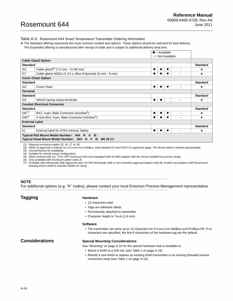
Reference Manual00809-0400-4728, Rev AA
June 2011Rosemount 644
NOTEFor additional options (e.g. “K” codes), please contact your local Emerson Process Management representative.
Tagging Hardware• 13 characters total
• Tags are adhesive labels
• Permanently attached to transmitter
• Character height is 1/16-in (1.6 mm)
Software • The transmitter can store up to 13 characters for FOUNDATION fieldbus and Profibus PA. If no
characters are specified, the first 8 characters of the hardware tag are the default.
Considerations Special Mounting ConsiderationsSee “Mounting” on page A-10 for the special hardware that is available to:
• Mount a 644H to a DIN rail. (see Table 1 on page A-15)
• Retrofit a new 644H to replace an existing 644H transmitter in an existing threaded sensor connection head (see Table 1 on page A-15).
Cable Gland Option
Standard Standard
G2 Cable gland(6) (7.5 mm - 11.99 mm) ● ● ● – ★
G7 Cable gland, M20x1.5, Ex e, Blue Polyamide (5 mm - 9 mm) ● ● ● – ★
Cover Chain Option
Standard Standard
G3 Cover chain ● ● ● – ★
Terminal
Standard Standard
G5 WAGO spring clamp terminals ● ● – ★
Conduit Electrical Connector
Standard Standard
GE(7) M12, 4-pin, Male Connector (eurofast®) ● ● ● – ★
GM(7) A size Mini, 4-pin, Male Connector (minifast®) ● ● ● – ★
External Label
Standard Standard
EL External label for ATEX Intrinsic Safety ● ● ● – ★
Typical Rail Mount Model Number: 644 R A I5Typical Head Mount Model Number: 644 H F I5 M5 J5 C1
(1) Requires enclosure option J5, J6, J7, or J8.(2) When IS approval is ordered on a FOUNDATION fieldbus, both standard IS and FISCO IS approvals apply. The device label is marked appropriately.(3) Consult factory for availability.(4) Suitable for remote mount configuration.(5) When ordered with XA, 1/2-in. NPT enclosure will come equipped with an M20 adapter with the sensor installed as process ready.(6) Only available with Enclosure option code J5.(7) Available with Intrinsically Safe approvals only. For FM Intrinsically Safe or non-incendive approval (option code I5), install in accordance with Rosemount
drawing 03151-1009 to maintain NEMA 4X rating.
Table A-3. Rosemount 644 Smart Temperature Transmitter Ordering Information★ The Standard offering represents the most common models and options. These options should be selected for best delivery.__The Expanded offering is manufactured after receipt of order and is subject to additional delivery lead time.
● = Available– = Not Available
A-14
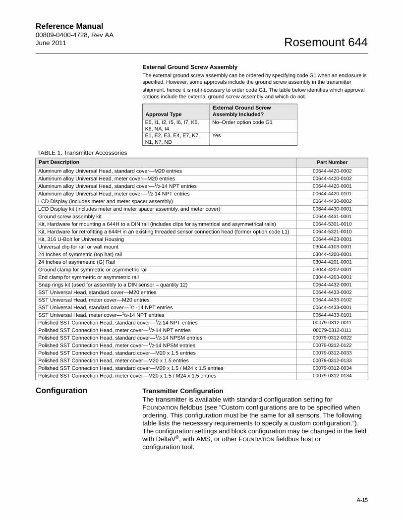
Reference Manual 00809-0400-4728, Rev AAJune 2011 Rosemount 644
External Ground Screw AssemblyThe external ground screw assembly can be ordered by specifying code G1 when an enclosure is specified. However, some approvals include the ground screw assembly in the transmitter
shipment, hence it is not necessary to order code G1. The table below identifies which approval options include the external ground screw assembly and which do not.
Configuration Transmitter ConfigurationThe transmitter is available with standard configuration setting for FOUNDATION fieldbus (see “Custom configurations are to be specified when ordering. This configuration must be the same for all sensors. The following table lists the necessary requirements to specify a custom configuration.”). The configuration settings and block configuration may be changed in the field with DeltaV®, with AMS, or other FOUNDATION fieldbus host or configuration tool.
Approval TypeExternal Ground Screw Assembly Included?
E5, I1, I2, I5, I6, I7, K5, K6, NA, I4
No–Order option code G1
E1, E2, E3, E4, E7, K7, N1, N7, ND
Yes
TABLE 1. Transmitter Accessories
Part Description Part Number
Aluminum alloy Universal Head, standard cover—M20 entries 00644-4420-0002
Aluminum alloy Universal Head, meter cover—M20 entries 00644-4420-0102
Aluminum alloy Universal Head, standard cover—1/2-14 NPT entries 00644-4420-0001
Aluminum alloy Universal Head, meter cover—1/2-14 NPT entries 00644-4420-0101
LCD Display (includes meter and meter spacer assembly) 00644-4430-0002
LCD Display kit (includes meter and meter spacer assembly, and meter cover) 00644-4430-0001
Ground screw assembly kit 00644-4431-0001
Kit, Hardware for mounting a 644H to a DIN rail (includes clips for symmetrical and asymmetrical rails) 00644-5301-0010
Kit, Hardware for retrofitting a 644H in an existing threaded sensor connection head (former option code L1) 00644-5321-0010
Kit, 316 U-Bolt for Universal Housing 00644-4423-0001
Universal clip for rail or wall mount 03044-4103-0001
24 Inches of symmetric (top hat) rail 03044-4200-0001
24 Inches of asymmetric (G) Rail 03044-4201-0001
Ground clamp for symmetric or asymmetric rail 03044-4202-0001
End clamp for symmetric or asymmetric rail 03044-4203-0001
Snap rings kit (used for assembly to a DIN sensor – quantity 12) 00644-4432-0001
SST Universal Head, standard cover—M20 entries 00644-4433-0002
SST Universal Head, meter cover—M20 entries 00644-4433-0102
SST Universal Head, standard cover—1/2 -14 NPT entries 00644-4433-0001
SST Universal Head, meter cover—1/2-14 NPT entries 00644-4433-0101
Polished SST Connection Head, standard cover—1/2-14 NPT entries 00079-0312-0011
Polished SST Connection Head, meter cover—1/2-14 NPT entries 00079-0312-0111
Polished SST Connection Head, standard cover—1/2-14 NPSM entries 00079-0312-0022
Polished SST Connection Head, meter cover—1/2-14 NPSM entries 00079-0312-0122
Polished SST Connection Head, standard cover—M20 x 1.5 entries 00079-0312-0033
Polished SST Connection Head, meter cover—M20 x 1.5 entries 00079-0312-0133
Polished SST Connection Head, standard cover—M20 x 1.5 / M24 x 1.5 entries 00079-0312-0034
Polished SST Connection Head, meter cover—M20 x 1.5 / M24 x 1.5 entries 00079-0312-0134
A-15
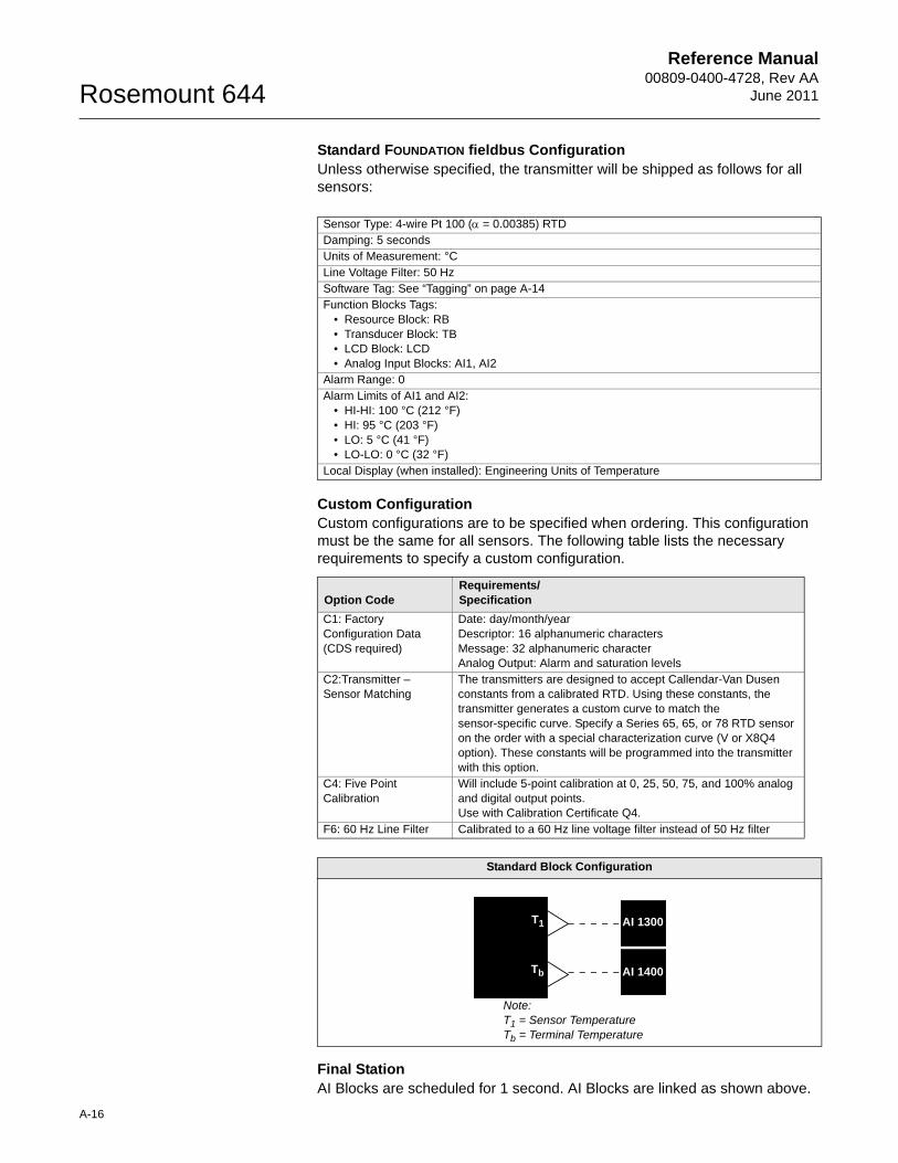
Reference Manual00809-0400-4728, Rev AA
June 2011Rosemount 644
A-16
Standard FOUNDATION fieldbus ConfigurationUnless otherwise specified, the transmitter will be shipped as follows for all sensors:
Custom ConfigurationCustom configurations are to be specified when ordering. This configuration must be the same for all sensors. The following table lists the necessary requirements to specify a custom configuration.
Final StationAI Blocks are scheduled for 1 second. AI Blocks are linked as shown above.
Sensor Type: 4-wire Pt 100 ( = 0.00385) RTDDamping: 5 secondsUnits of Measurement: °CLine Voltage Filter: 50 HzSoftware Tag: See “Tagging” on page A-14Function Blocks Tags:
• Resource Block: RB• Transducer Block: TB• LCD Block: LCD• Analog Input Blocks: AI1, AI2
Alarm Range: 0Alarm Limits of AI1 and AI2:
• HI-HI: 100 °C (212 °F)• HI: 95 °C (203 °F)• LO: 5 °C (41 °F)• LO-LO: 0 °C (32 °F)
Local Display (when installed): Engineering Units of Temperature
Option CodeRequirements/Specification
C1: Factory Configuration Data (CDS required)
Date: day/month/yearDescriptor: 16 alphanumeric charactersMessage: 32 alphanumeric characterAnalog Output: Alarm and saturation levels
C2:Transmitter – Sensor Matching
The transmitters are designed to accept Callendar-Van Dusen constants from a calibrated RTD. Using these constants, the transmitter generates a custom curve to match the sensor-specific curve. Specify a Series 65, 65, or 78 RTD sensor on the order with a special characterization curve (V or X8Q4 option). These constants will be programmed into the transmitter with this option.
C4: Five Point Calibration
Will include 5-point calibration at 0, 25, 50, 75, and 100% analog and digital output points. Use with Calibration Certificate Q4.
F6: 60 Hz Line Filter Calibrated to a 60 Hz line voltage filter instead of 50 Hz filter
Standard Block Configuration
T1
Tb
Note:T1 = Sensor TemperatureTb = Terminal Temperature
AI 1300
AI 1400
Reference Manual 00809-0100-4728, Rev AAJune 2011 Rosemount 644
Appendix B Product Certifications
Approved Manufacturing Locations . . . . . . . . . . . . . . . . . page B-1European Union Directive Information . . . . . . . . . . . . . . . page B-1Hazardous Locations Certificates . . . . . . . . . . . . . . . . . . . page B-2Installation Drawings . . . . . . . . . . . . . . . . . . . . . . . . . . . . . page B-7
APPROVED MANUFACTURING LOCATIONS
Emerson Process Management Rosemount Division. – Chanhassen, Minnesota, USA
Rosemount Temperature GmbH – Germany
Emerson Process Management Asia Pacific – Singapore
EUROPEAN UNION DIRECTIVE INFORMATION
The EC declaration of conformity for all applicable European directives for this product can be found on the Rosemount website at www.rosemount.com. A hard copy may be obtained by contacting our local sales representative.
ATEX Directive (94/9/EC)Rosemount Inc. complies with the ATEX Directive.
CE Electromagnetic Compatibility Compliance TestingThe 644 meets the criteria under IEC 61326:2006
www.rosemount.com
Reference Manual00809-0100-4728, Rev AA
June 2011Rosemount 644
HAZARDOUS LOCATIONS CERTIFICATES
Rosemount 644 with FOUNDATION fieldbus
North American Certifications
Factory Mutual (FM) Approvals
I5 FM Intrinsically Safe and Non-incendiveIntrinsically Safe FISCO for use in Class I, II, III, Division 1, Groups A, B, C, D, E, F, and G; when installed per control drawing 00644-2075.Temperature Code: T4A (Tamb = – 50 °C to 60 °C).
Nonincendive for use in Class I, Division 2, Groups A, B, C, and D. Temperature Code: T5 (Tamb = – 50 °C to 85 °C);
T6 (Tamb = – 50 °C to 70 °C)
When installed per Rosemount control drawing 00644-2075
E5 FM Explosion ProofExplosion Proof for Class I, Division 1, Groups B, C, and D.
Nonincendive for use in Class 1, Division 2, Groups A, B, C, and D.
Temperature Code: T5 (Tamb = – 50 °C to 85 °C)When installed per Rosemount control drawing 00644-1049
Dust Ignition Proof for Class II/III, Division 1, Groups E, F, G.Temperature Code: T5 (Ta = – 50 °C to 85 °C)
When installed per Rosemount drawing 00644-1049. (J5, J6 and J8 options only.)
Canadian Standards Association (CSA) Approvals
I6 CSA Intrinsically SafeIntrinsically Safe and FISCO for Class I, Division 1, groups A, B, C, and D when connected per Rosemount drawing 00644-2076.
Temperature code: T4 (Tamb = – 50 °C to 60 °C);
Suitable for Class I, Division 2, groups A, B, C, and D (must be installed in a suitable enclosure)
K6 CSA Intrinsically Safe, Explosion-proofIncludes Intrinsically Safe “I6” and Explosion-Proof for Class I, Division 1, groups B, C, and D.Dust-Ignition Proof for Class II, Division 1, Groups E, F, and G. Dust-Ignition Proof for Class III, Division 1Seal not required. CSA Enclosure Type 4X
Temperature Code: T4 (Tamb = – 50 °C to 60 °C); T5 (Tamb = – 50 °C to 85 °C)
NOTE: (For J5 and J6 enclosure options only)
B-2
Reference Manual 00809-0100-4728, Rev AAJune 2011 Rosemount 644
European Certifications E1 ATEX Flame-ProofCertificate Number: KEMA99ATEX8715XATEX Marking: II 2 G
1180Ex d IIC T6 (–50 °C Tamb 65 °C)U = 32 Vdc
Special Conditions for Safe Use (X):For information on the dimensions of the flameproof joints the manufacturer shall be contacted.
I1 ATEX Intrinsic SafetyCertificate Number: Baseefa03ATEX0499XATEX Marking: II 1 G
1180Ex ia IIC T4 (-50 °C Tamb 60 °C)
Special Conditions for Safe Use (X):The apparatus must be installed in an enclosure which affords it a degree of protection of at least IP20. Non-metallic enclosures must have a surface resistance of less than 1G�, light alloy or zirconium enclosures must be protected from impact and friction when installed.
N1 ATEX Type nCertificate Number: BAS00ATEX3145ATEX Marking: II 3 G Ex nL IIC T5 (-40 °C Tamb 70 °C)Ui = 32 V
I.S. Loop/Power Terminals
Ui = 30 VIi = 300 mAPi = 1.3 WCi = 2.1 nFLi = 0
FISCO Loop/Power Terminals
Ui = 17.5 VIi = 380 mAPi = 5.32 WCi = 2.1 nFLi = 0
Sensor Terminals
Uo = 13.9 VIo = 23 mAPo = 79 mWCi = 7.7 nFLi = 0
B-3
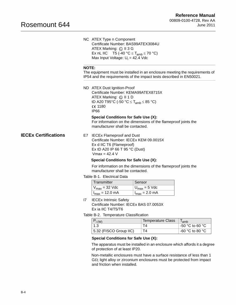
Reference Manual00809-0100-4728, Rev AA
June 2011Rosemount 644
NC ATEX Type n ComponentCertificate Number: BAS99ATEX3084UATEX Marking: II 3 G Ex nL IIC T5 (-40 °C Tamb 70 °C)Max Input Voltage: Ui = 42.4 Vdc
NOTE:The equipment must be installed in an enclosure meeting the requirements of IP54 and the requirements of the impact tests described in EN50021.
ND ATEX Dust Ignition-ProofCertificate Number: KEMA99ATEX8715XATEX Marking: II 1 D tD A20 T95°C (-50 °C Tamb 85 °C)
1180IP66
Special Conditions for Safe Use (X):For information on the dimensions of the flameproof joints the manufacturer shall be contacted.
IECEx Certifications E7 IECEx Flameproof and DustCertificate Number: IECEx KEM 09.0015XEx d IIC T6 (Flameproof)Ex tD A20 IP 66 T 95 °C (Dust)Vmax = 42.4 V
Special Conditions for Safe Use (X):
For information on the dimensions of the flameproof joints the manufacturer shall be contacted.
I7 IECEx Intrinsic Safety Certificate Number: IECEx BAS 07.0053XEx ia IIC T4/T5/T6
Special Conditions for Safe Use (X):
The apparatus must be installed in an enclosure which affords it a degree of protection of at least IP20.
Non-metallic enclosures must have a surface resistance of less than 1 G�; light alloy or zirconium enclosures must be protected from impact and friction when installed.
Table B-1. Electrical Data
Transmitter SensorVmax = 32 Vdc Umax = 5 VdcImax = 12.0 mA Imax = 2.0 mA
Table B-2. Temperature Classification
Pi (W) Temperature Class Tamb1.3 T4 -50 °C to 60 °C5.32 (FISCO Group IIC) T4 -60 °C to 80 °C
B-4
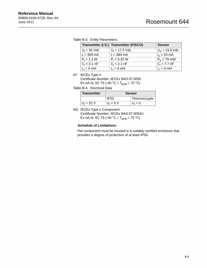
Reference Manual 00809-0100-4728, Rev AAJune 2011 Rosemount 644
N7 IECEx Type nCertificate Number: IECEx BAS 07.0055Ex nA nL IIC T5 (-40 °C Tamb 70 °C)
NG IECEx Type n ComponentCertificate Number: IECEx BAS 07.0054UEx nA nL IIC T5 (-40 °C Tamb 75 °C)
Schedule of Limitations:
The component must be housed in a suitably certified enclosure that provides a degree of protection of at least IP54.
Table B-3. Entity Parameters
Transmitter (I.S.) Transmitter (FISCO) Sensor
Ui = 30 Vdc Ui = 17.5 Vdc Uo = 13.9 VdcIi = 300 mA Ii = 380 mA Io = 23 mAPi = 1.3 W Pi = 5.32 W Po = 79 mWCi = 2.1 nF Ci = 2.1 nF Ci = 7.7 nFLi = 0 mH Li = 0 mH Li = 0 mH
Table B-4. Electrical Data
Transmitter Sensor
RTD ThermocoupleUi = 32 V Ui = 5 V Ui = 0
B-5
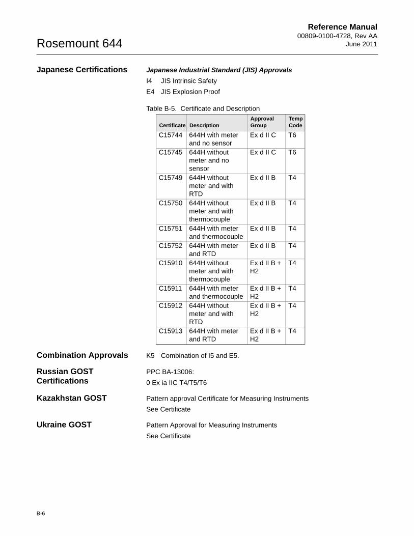
Reference Manual00809-0100-4728, Rev AA
June 2011Rosemount 644
Japanese Certifications Japanese Industrial Standard (JIS) Approvals
I4 JIS Intrinsic Safety
E4 JIS Explosion Proof
Combination Approvals K5 Combination of I5 and E5.
Russian GOST Certifications
PPC BA-13006:
0 Ex ia IIC T4/T5/T6
Kazakhstan GOST Pattern approval Certificate for Measuring Instruments
See Certificate
Ukraine GOST Pattern Approval for Measuring Instruments
See Certificate
Table B-5. Certificate and Description
Certificate DescriptionApproval Group
TempCode
C15744 644H with meter and no sensor
Ex d II C T6
C15745 644H without meter and no sensor
Ex d II C T6
C15749 644H without meter and with RTD
Ex d II B T4
C15750 644H without meter and with thermocouple
Ex d II B T4
C15751 644H with meter and thermocouple
Ex d II B T4
C15752 644H with meter and RTD
Ex d II B T4
C15910 644H without meter and with thermocouple
Ex d II B + H2
T4
C15911 644H with meter and thermocouple
Ex d II B + H2
T4
C15912 644H without meter and with RTD
Ex d II B + H2
T4
C15913 644H with meter and RTD
Ex d II B + H2
T4
B-6
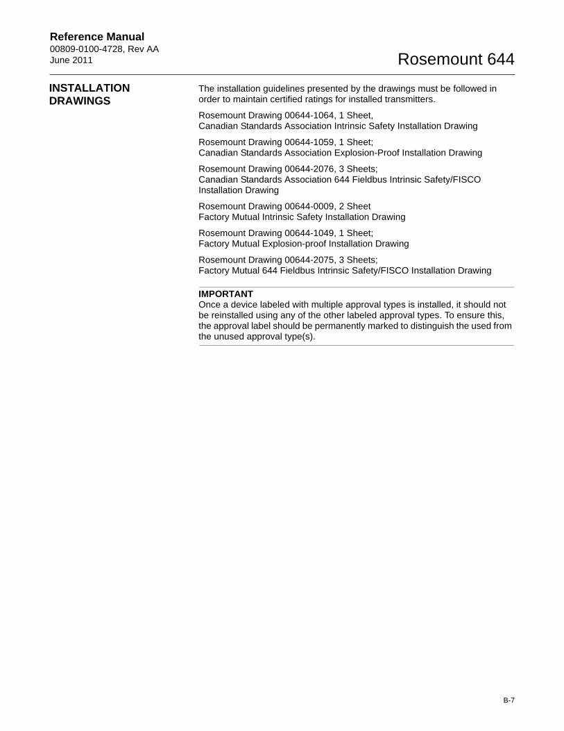
Reference Manual 00809-0100-4728, Rev AAJune 2011 Rosemount 644
B-7
INSTALLATION DRAWINGS
The installation guidelines presented by the drawings must be followed in order to maintain certified ratings for installed transmitters.
Rosemount Drawing 00644-1064, 1 Sheet, Canadian Standards Association Intrinsic Safety Installation Drawing
Rosemount Drawing 00644-1059, 1 Sheet;Canadian Standards Association Explosion-Proof Installation Drawing
Rosemount Drawing 00644-2076, 3 Sheets;Canadian Standards Association 644 Fieldbus Intrinsic Safety/FISCO Installation Drawing
Rosemount Drawing 00644-0009, 2 SheetFactory Mutual Intrinsic Safety Installation Drawing
Rosemount Drawing 00644-1049, 1 Sheet;Factory Mutual Explosion-proof Installation Drawing
Rosemount Drawing 00644-2075, 3 Sheets;Factory Mutual 644 Fieldbus Intrinsic Safety/FISCO Installation Drawing
IMPORTANTOnce a device labeled with multiple approval types is installed, it should not be reinstalled using any of the other labeled approval types. To ensure this, the approval label should be permanently marked to distinguish the used from the unused approval type(s).
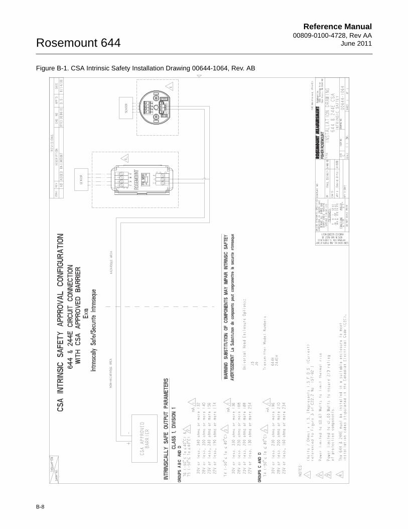
Reference Manual00809-0100-4728, Rev AA
June 2011Rosemount 644
Figure B-1. CSA Intrinsic Safety Installation Drawing 00644-1064, Rev. AB
B-8
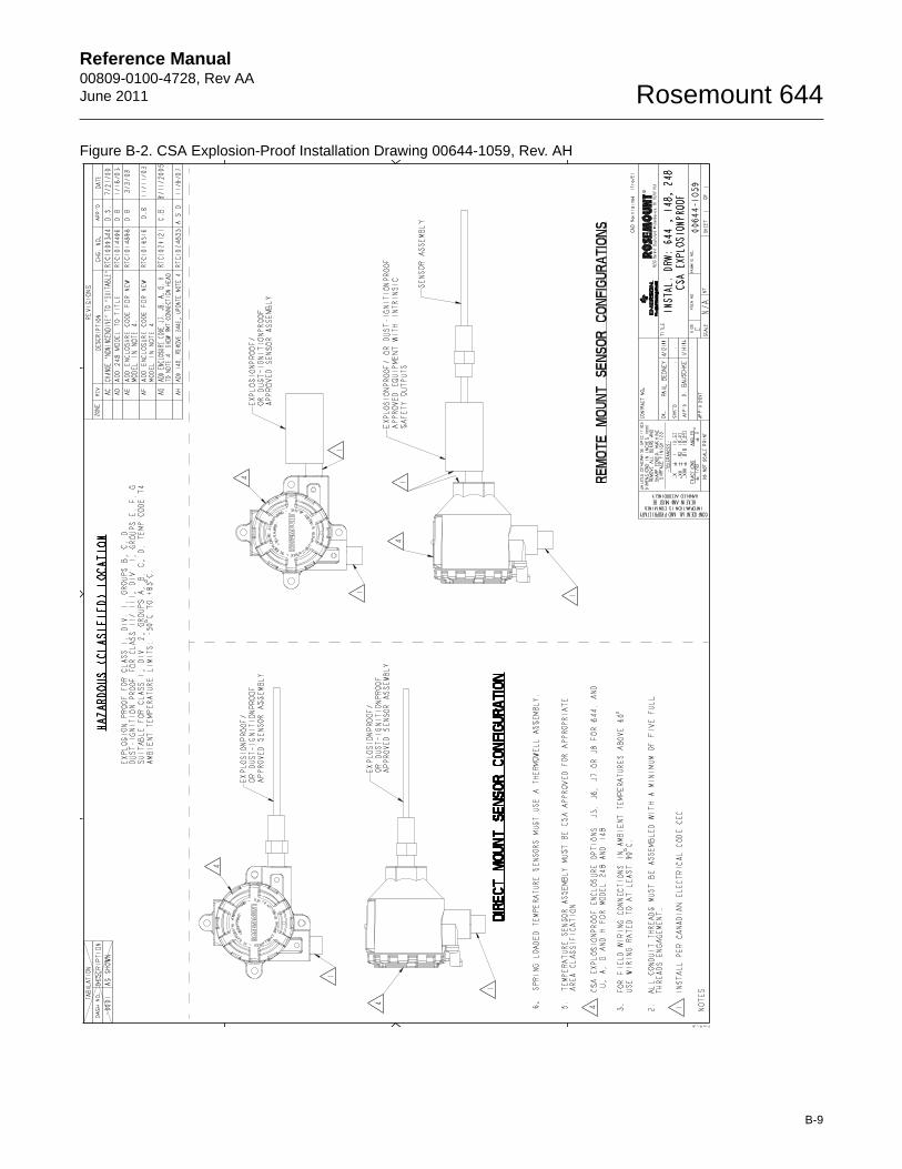
Reference Manual 00809-0100-4728, Rev AAJune 2011 Rosemount 644
Figure B-2. CSA Explosion-Proof Installation Drawing 00644-1059, Rev. AH
B-9
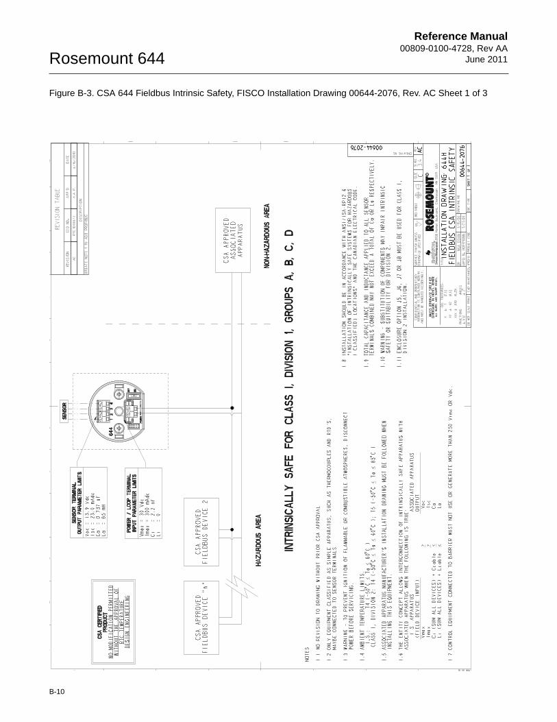
Reference Manual00809-0100-4728, Rev AA
June 2011Rosemount 644
Figure B-3. CSA 644 Fieldbus Intrinsic Safety, FISCO Installation Drawing 00644-2076, Rev. AC Sheet 1 of 3
B-10
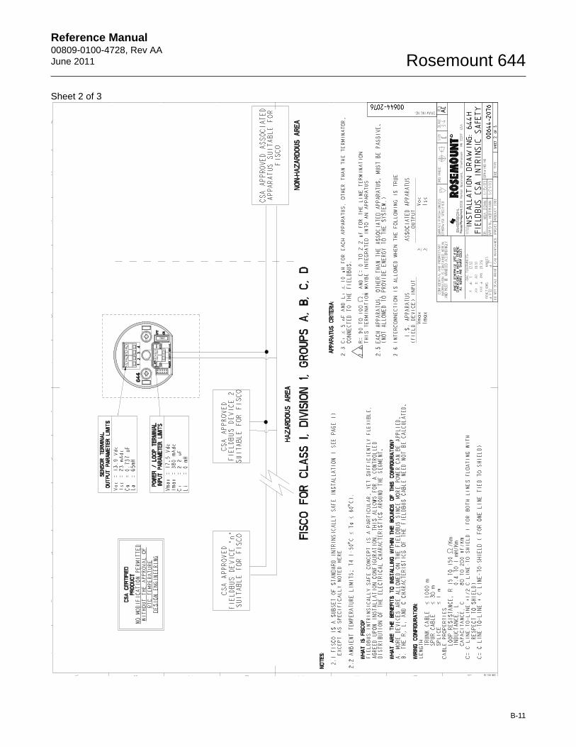
Reference Manual 00809-0100-4728, Rev AAJune 2011 Rosemount 644
Sheet 2 of 3
B-11
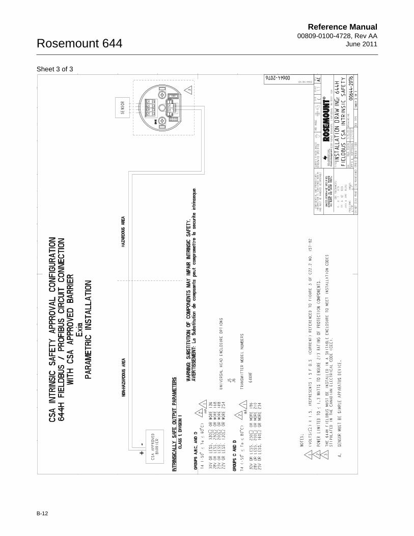
Reference Manual00809-0100-4728, Rev AA
June 2011Rosemount 644
Sheet 3 of 3
B-12
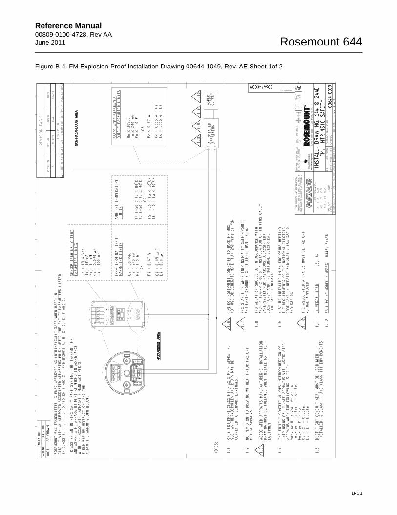
Reference Manual 00809-0100-4728, Rev AAJune 2011 Rosemount 644
Figure B-4. FM Explosion-Proof Installation Drawing 00644-1049, Rev. AE Sheet 1of 2
B-13
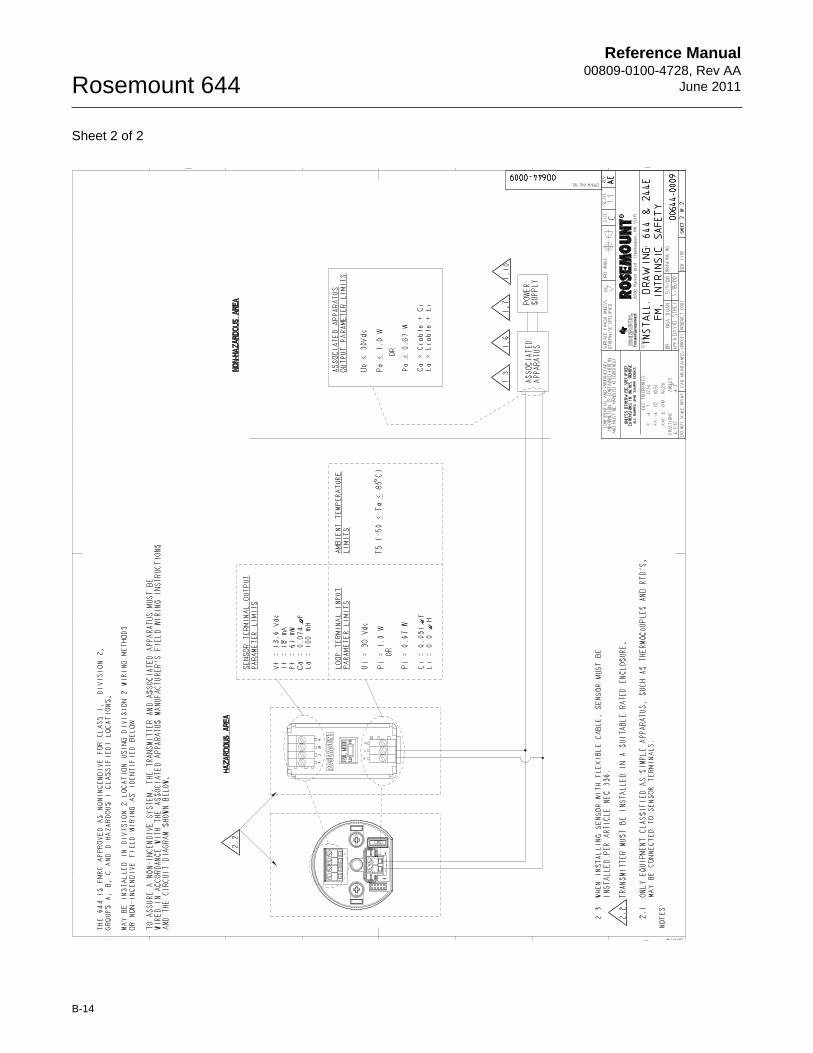
Reference Manual00809-0100-4728, Rev AA
June 2011Rosemount 644
Sheet 2 of 2
B-14
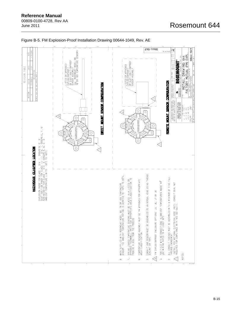
Reference Manual 00809-0100-4728, Rev AAJune 2011 Rosemount 644
Figure B-5. FM Explosion-Proof Installation Drawing 00644-1049, Rev. AE
B-15
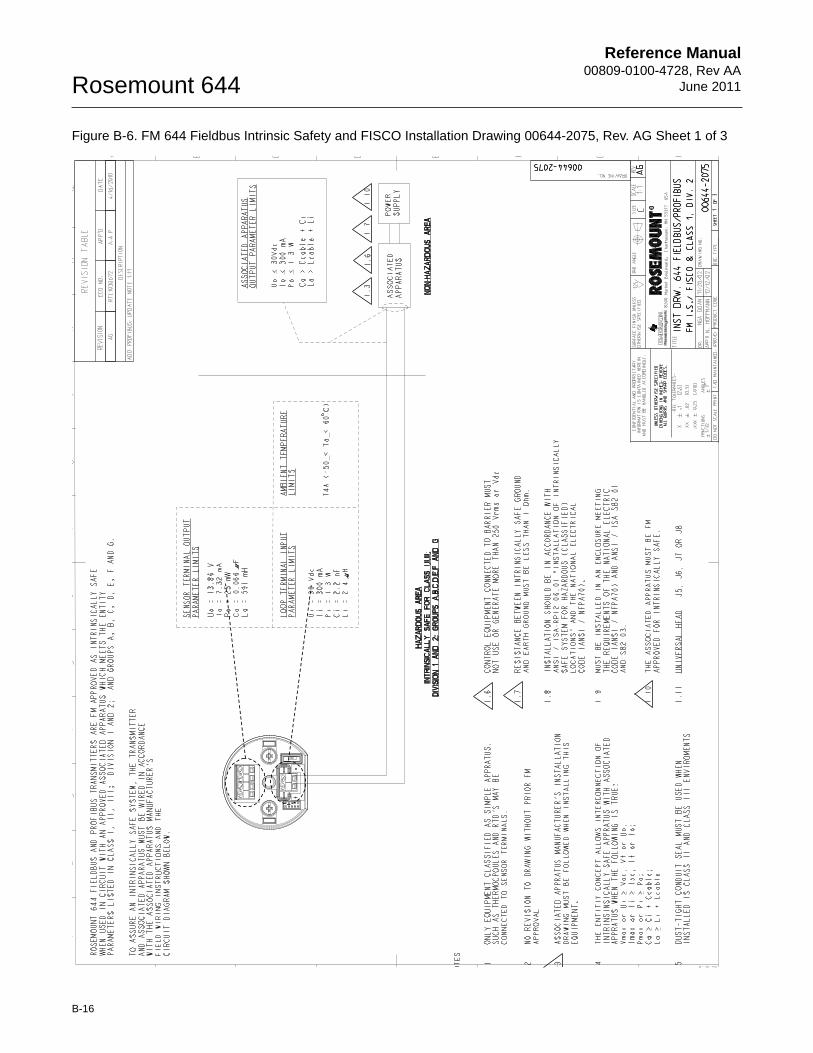
Reference Manual00809-0100-4728, Rev AA
June 2011Rosemount 644
Figure B-6. FM 644 Fieldbus Intrinsic Safety and FISCO Installation Drawing 00644-2075, Rev. AG Sheet 1 of 3
B-16
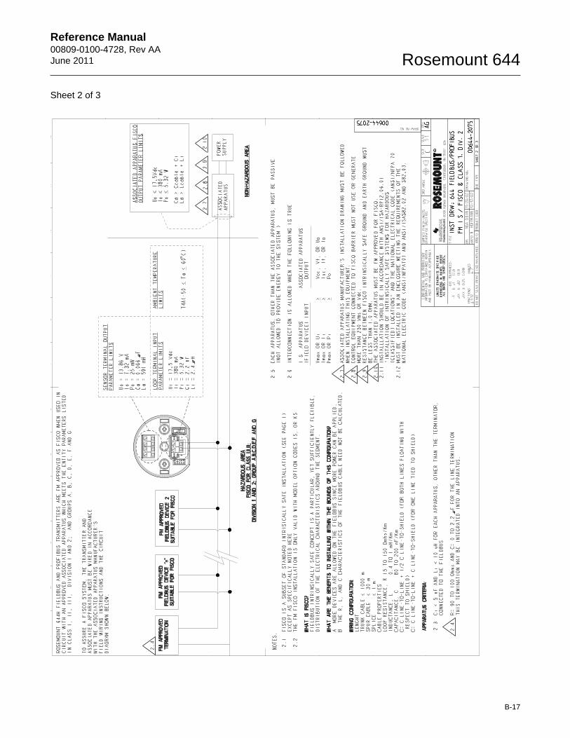
Reference Manual 00809-0100-4728, Rev AAJune 2011 Rosemount 644
Sheet 2 of 3
B-17
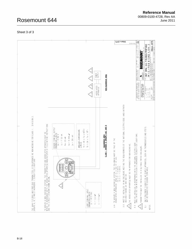
Reference Manual00809-0100-4728, Rev AA
June 2011Rosemount 644
Sheet 3 of 3
B-18
Reference Manual00809-0400-4728, Rev AAJune 2011 Rosemount 644
Appendix C FOUNDATION fieldbus Block Information
Resource Block . . . . . . . . . . . . . . . . . . . . . . . . . . . . . . . . . . page C-1Sensor Transducer Block . . . . . . . . . . . . . . . . . . . . . . . . . page C-5Analog Input (AI) Function Block . . . . . . . . . . . . . . . . . . . page C-8LCD Transducer Block . . . . . . . . . . . . . . . . . . . . . . . . . . . . page C-11PID Block . . . . . . . . . . . . . . . . . . . . . . . . . . . . . . . . . . . . . . . page C-12BASIC SETUP
RESOURCE BLOCK This section contains information on the 644 Resource Block. Descriptions of all Resource Block Parameters, errors, and diagnostics are included. Also the modes, alarm detection, status handling, and troubleshooting are discussed.
Definition
The resource block defines the physical resources of the device. The resource block also handles functionality that is common across multiple blocks. The block has no linkable inputs or outputs.
www.rosemount.com
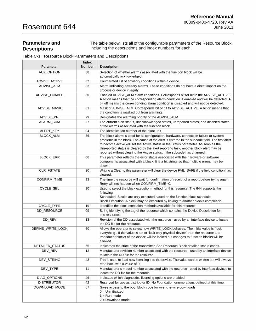
Reference Manual00809-0400-4728, Rev AA
June 2011Rosemount 644
Parameters and Descriptions
The table below lists all of the configurable parameters of the Resource Block, including the descriptions and index numbers for each.
Table C-1. Resource Block Parameters and Descriptions
ParameterIndex
Number Description
ACK_OPTION 38 Selection of whether alarms associated with the function block will be automatically acknowledged.
ADVISE_ACTIVE 82 Enumerated list of advisory conditions within a device.
ADVISE_ALM 83 Alarm indicating advisory alarms. These conditions do not have a direct impact on the process or device integrity.
ADVISE_ENABLE 80 Enabled ADVISE_ALM alarm conditions. Corresponds bit for bit to the ADVISE_ACTIVE. A bit on means that the corresponding alarm condition is enabled and will be detected. A bit off means the corresponding alarm condition is disabled and will not be detected.
ADVISE_MASK 81 Mask of ADVISE_ALM. Corresponds bit of bit to ADVISE_ACTIVE. A bit on means that the condition is masked out from alarming.
ADVISE_PRI 79 Designates the alarming priority of the ADVISE_ALM
ALARM_SUM 37 The current alert status, unacknowledged states, unreported states, and disabled states of the alarms associated with the function block.
ALERT_KEY 04 The identification number of the plant unit.
BLOCK_ALM 36 The block alarm is used for all configuration, hardware, connection failure or system problems in the block. The cause of the alert is entered in the subcode field. The first alert to become active will set the Active status in the Status parameter. As soon as the Unreported status is cleared by the alert reporting task, another block alert may be reported without clearing the Active status, if the subcode has changed.
BLOCK_ERR 06 This parameter reflects the error status associated with the hardware or software components associated with a block. It is a bit string, so that multiple errors may be shown.
CLR_FSTATE 30 Writing a Clear to this parameter will clear the device FAIL_SAFE if the field condition has cleared.
CONFIRM_TIME 33 The time the resource will wait for confirmation of receipt of a report before trying again. Retry will not happen when CONFIRM_TIME=0.
CYCLE_SEL 20 Used to select the block execution method for this resource. The 644 supports the following:Scheduled: Blocks are only executed based on the function block schedule.Block Execution: A block may be executed by linking to another blocks completion.
CYCLE_TYPE 19 Identifies the block execution methods available for this resource.
DD_RESOURCE 09 String identifying the tag of the resource which contains the Device Description for this resource.
DD_REV 13 Revision of the DD associated with the resource - used by an interface device to locate the DD file for the resource.
DEFINE_WRITE_LOCK 60 Allows the operator to select how WRITE_LOCK behaves. The initial value is “lock everything”. If the value is set to “lock only physical device” then the resource and transducer blocks of the device will be locked but changes to function blocks will be allowed.
DETAILED_STATUS 55 Indicateds the state of the transmitter. See Resource Block detailed status codes.
DEV_REV 12 Manufacturer revision number associated with the resource - used by an interface device to locate the DD file for the resource.
DEV_STRING 43 This is used to load new licensing into the device. The value can be written but will always read back with a value of 0.
DEV_TYPE 11 Manufacturer’s model number associated with the resource - used by interface devices to locate the DD file for the resource.
DIAG_OPTIONS 46 Indicates which diagnostics licensing options are enabled.
DISTRIBUTOR 42 Reserved for use as distributor ID. No Foundation enumerations defined at this time.
DOWNLOAD_MODE 67 Gives access to the boot block code for over-the-wire downloads.0 = Uninitialized 1 = Run mode2 = Download mode
C-2
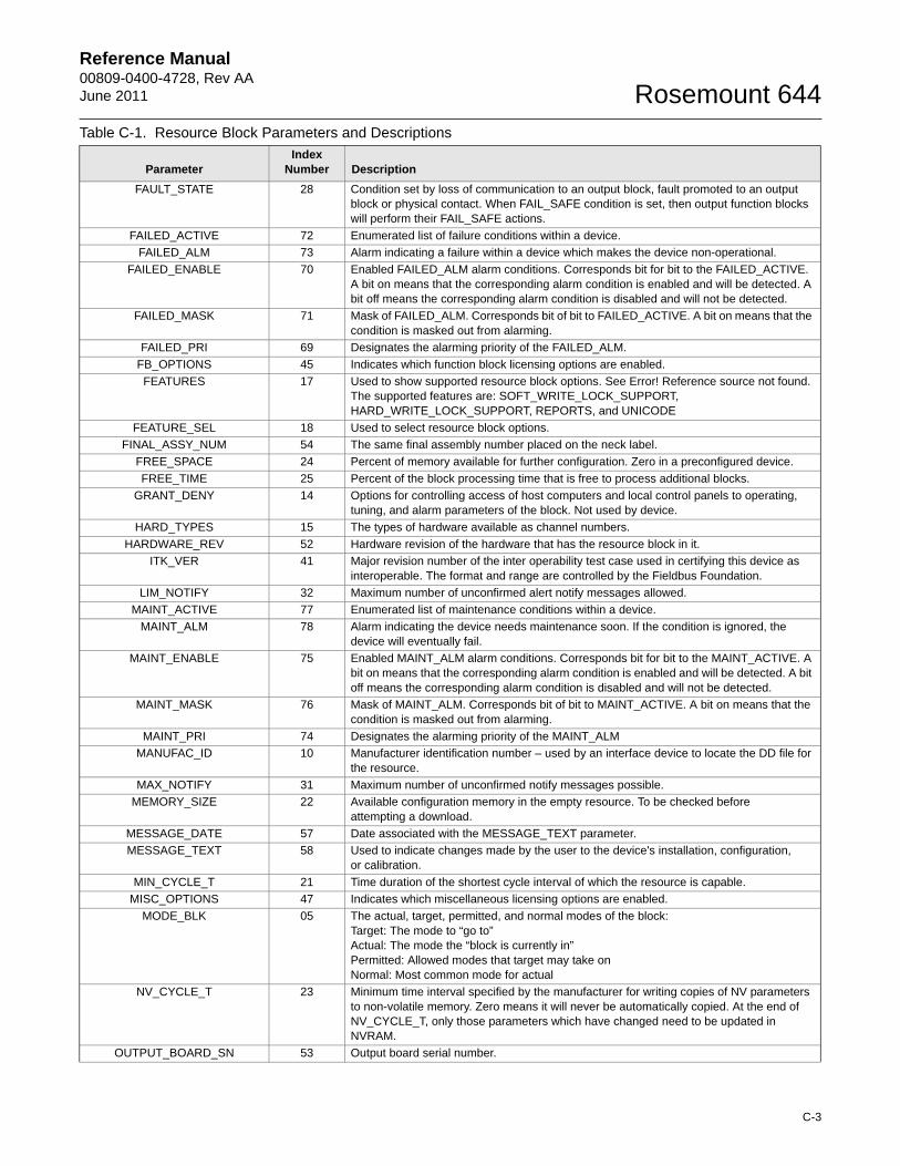
Reference Manual00809-0400-4728, Rev AAJune 2011 Rosemount 644
FAULT_STATE 28 Condition set by loss of communication to an output block, fault promoted to an output block or physical contact. When FAIL_SAFE condition is set, then output function blocks will perform their FAIL_SAFE actions.
FAILED_ACTIVE 72 Enumerated list of failure conditions within a device.
FAILED_ALM 73 Alarm indicating a failure within a device which makes the device non-operational.
FAILED_ENABLE 70 Enabled FAILED_ALM alarm conditions. Corresponds bit for bit to the FAILED_ACTIVE. A bit on means that the corresponding alarm condition is enabled and will be detected. A bit off means the corresponding alarm condition is disabled and will not be detected.
FAILED_MASK 71 Mask of FAILED_ALM. Corresponds bit of bit to FAILED_ACTIVE. A bit on means that the condition is masked out from alarming.
FAILED_PRI 69 Designates the alarming priority of the FAILED_ALM.
FB_OPTIONS 45 Indicates which function block licensing options are enabled.
FEATURES 17 Used to show supported resource block options. See Error! Reference source not found. The supported features are: SOFT_WRITE_LOCK_SUPPORT, HARD_WRITE_LOCK_SUPPORT, REPORTS, and UNICODE
FEATURE_SEL 18 Used to select resource block options.
FINAL_ASSY_NUM 54 The same final assembly number placed on the neck label.
FREE_SPACE 24 Percent of memory available for further configuration. Zero in a preconfigured device.
FREE_TIME 25 Percent of the block processing time that is free to process additional blocks.
GRANT_DENY 14 Options for controlling access of host computers and local control panels to operating, tuning, and alarm parameters of the block. Not used by device.
HARD_TYPES 15 The types of hardware available as channel numbers.
HARDWARE_REV 52 Hardware revision of the hardware that has the resource block in it.
ITK_VER 41 Major revision number of the inter operability test case used in certifying this device as interoperable. The format and range are controlled by the Fieldbus Foundation.
LIM_NOTIFY 32 Maximum number of unconfirmed alert notify messages allowed.
MAINT_ACTIVE 77 Enumerated list of maintenance conditions within a device.
MAINT_ALM 78 Alarm indicating the device needs maintenance soon. If the condition is ignored, the device will eventually fail.
MAINT_ENABLE 75 Enabled MAINT_ALM alarm conditions. Corresponds bit for bit to the MAINT_ACTIVE. A bit on means that the corresponding alarm condition is enabled and will be detected. A bit off means the corresponding alarm condition is disabled and will not be detected.
MAINT_MASK 76 Mask of MAINT_ALM. Corresponds bit of bit to MAINT_ACTIVE. A bit on means that the condition is masked out from alarming.
MAINT_PRI 74 Designates the alarming priority of the MAINT_ALM
MANUFAC_ID 10 Manufacturer identification number – used by an interface device to locate the DD file for the resource.
MAX_NOTIFY 31 Maximum number of unconfirmed notify messages possible.
MEMORY_SIZE 22 Available configuration memory in the empty resource. To be checked before attempting a download.
MESSAGE_DATE 57 Date associated with the MESSAGE_TEXT parameter.
MESSAGE_TEXT 58 Used to indicate changes made by the user to the device's installation, configuration,or calibration.
MIN_CYCLE_T 21 Time duration of the shortest cycle interval of which the resource is capable.
MISC_OPTIONS 47 Indicates which miscellaneous licensing options are enabled.
MODE_BLK 05 The actual, target, permitted, and normal modes of the block:Target: The mode to “go to”Actual: The mode the “block is currently in”Permitted: Allowed modes that target may take onNormal: Most common mode for actual
NV_CYCLE_T 23 Minimum time interval specified by the manufacturer for writing copies of NV parameters to non-volatile memory. Zero means it will never be automatically copied. At the end of NV_CYCLE_T, only those parameters which have changed need to be updated in NVRAM.
OUTPUT_BOARD_SN 53 Output board serial number.
Table C-1. Resource Block Parameters and Descriptions
ParameterIndex
Number Description
C-3
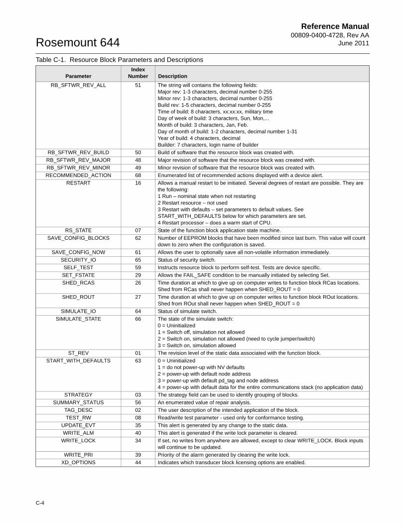
Reference Manual00809-0400-4728, Rev AA
June 2011Rosemount 644
RB_SFTWR_REV_ALL 51 The string will contains the following fields:Major rev: 1-3 characters, decimal number 0-255Minor rev: 1-3 characters, decimal number 0-255Build rev: 1-5 characters, decimal number 0-255Time of build: 8 characters, xx:xx:xx, military timeDay of week of build: 3 characters, Sun, Mon,...Month of build: 3 characters, Jan, Feb.Day of month of build: 1-2 characters, decimal number 1-31Year of build: 4 characters, decimalBuilder: 7 characters, login name of builder
RB_SFTWR_REV_BUILD 50 Build of software that the resource block was created with.
RB_SFTWR_REV_MAJOR 48 Major revision of software that the resource block was created with.
RB_SFTWR_REV_MINOR 49 Minor revision of software that the resource block was created with.
RECOMMENDED_ACTION 68 Enumerated list of recommended actions displayed with a device alert.
RESTART 16 Allows a manual restart to be initiated. Several degrees of restart are possible. They are the following:1 Run – nominal state when not restarting2 Restart resource – not used 3 Restart with defaults – set parameters to default values. See START_WITH_DEFAULTS below for which parameters are set.4 Restart processor – does a warm start of CPU.
RS_STATE 07 State of the function block application state machine.
SAVE_CONFIG_BLOCKS 62 Number of EEPROM blocks that have been modified since last burn. This value will count down to zero when the configuration is saved.
SAVE_CONFIG_NOW 61 Allows the user to optionally save all non-volatile information immediately.
SECURITY_IO 65 Status of security switch.
SELF_TEST 59 Instructs resource block to perform self-test. Tests are device specific.
SET_FSTATE 29 Allows the FAIL_SAFE condition to be manually initiated by selecting Set.
SHED_RCAS 26 Time duration at which to give up on computer writes to function block RCas locations. Shed from RCas shall never happen when SHED_ROUT = 0
SHED_ROUT 27 Time duration at which to give up on computer writes to function block ROut locations. Shed from ROut shall never happen when SHED_ROUT = 0
SIMULATE_IO 64 Status of simulate switch.
SIMULATE_STATE 66 The state of the simulate switch:0 = Uninitialized1 = Switch off, simulation not allowed2 = Switch on, simulation not allowed (need to cycle jumper/switch)3 = Switch on, simulation allowed
ST_REV 01 The revision level of the static data associated with the function block.
START_WITH_DEFAULTS 63 0 = Uninitialized1 = do not power-up with NV defaults2 = power-up with default node address3 = power-up with default pd_tag and node address4 = power-up with default data for the entire communications stack (no application data)
STRATEGY 03 The strategy field can be used to identify grouping of blocks.
SUMMARY_STATUS 56 An enumerated value of repair analysis.
TAG_DESC 02 The user description of the intended application of the block.
TEST_RW 08 Read/write test parameter - used only for conformance testing.
UPDATE_EVT 35 This alert is generated by any change to the static data.
WRITE_ALM 40 This alert is generated if the write lock parameter is cleared.
WRITE_LOCK 34 If set, no writes from anywhere are allowed, except to clear WRITE_LOCK. Block inputs will continue to be updated.
WRITE_PRI 39 Priority of the alarm generated by clearing the write lock.
XD_OPTIONS 44 Indicates which transducer block licensing options are enabled.
Table C-1. Resource Block Parameters and Descriptions
ParameterIndex
Number Description
C-4
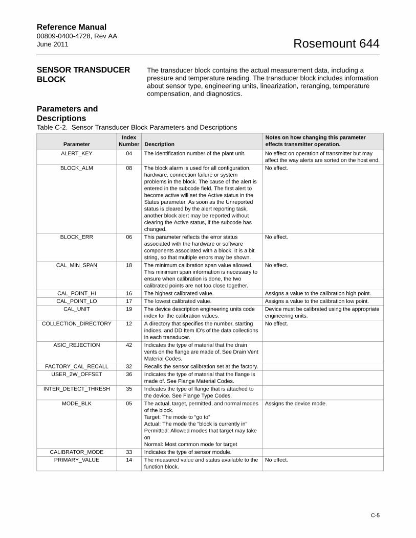
Reference Manual00809-0400-4728, Rev AAJune 2011 Rosemount 644
SENSOR TRANSDUCER BLOCK
The transducer block contains the actual measurement data, including a pressure and temperature reading. The transducer block includes information about sensor type, engineering units, linearization, reranging, temperature compensation, and diagnostics.
Parameters and DescriptionsTable C-2. Sensor Transducer Block Parameters and Descriptions
ParameterIndex
Number DescriptionNotes on how changing this parameter effects transmitter operation.
ALERT_KEY 04 The identification number of the plant unit. No effect on operation of transmitter but may affect the way alerts are sorted on the host end.
BLOCK_ALM 08 The block alarm is used for all configuration, hardware, connection failure or system problems in the block. The cause of the alert is entered in the subcode field. The first alert to become active will set the Active status in the Status parameter. As soon as the Unreported status is cleared by the alert reporting task, another block alert may be reported without clearing the Active status, if the subcode has changed.
No effect.
BLOCK_ERR 06 This parameter reflects the error status associated with the hardware or software components associated with a block. It is a bit string, so that multiple errors may be shown.
No effect.
CAL_MIN_SPAN 18 The minimum calibration span value allowed. This minimum span information is necessary to ensure when calibration is done, the two calibrated points are not too close together.
No effect.
CAL_POINT_HI 16 The highest calibrated value. Assigns a value to the calibration high point.
CAL_POINT_LO 17 The lowest calibrated value. Assigns a value to the calibration low point.
CAL_UNIT 19 The device description engineering units code index for the calibration values.
Device must be calibrated using the appropriate engineering units.
COLLECTION_DIRECTORY 12 A directory that specifies the number, starting indices, and DD Item ID's of the data collections in each transducer.
No effect.
ASIC_REJECTION 42 Indicates the type of material that the drain vents on the flange are made of. See Drain Vent Material Codes.
FACTORY_CAL_RECALL 32 Recalls the sensor calibration set at the factory.
USER_2W_OFFSET 36 Indicates the type of material that the flange is made of. See Flange Material Codes.
INTER_DETECT_THRESH 35 Indicates the type of flange that is attached to the device. See Flange Type Codes.
MODE_BLK 05 The actual, target, permitted, and normal modes of the block.Target: The mode to “go to”Actual: The mode the “block is currently in”Permitted: Allowed modes that target may take onNormal: Most common mode for target
Assigns the device mode.
CALIBRATOR_MODE 33 Indicates the type of sensor module.
PRIMARY_VALUE 14 The measured value and status available to the function block.
No effect.
C-5
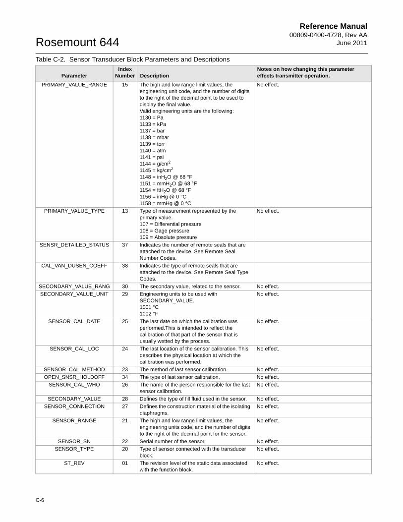
Reference Manual00809-0400-4728, Rev AA
June 2011Rosemount 644
PRIMARY_VALUE_RANGE 15 The high and low range limit values, the engineering unit code, and the number of digits to the right of the decimal point to be used to display the final value.Valid engineering units are the following: 1130 = Pa1133 = kPa1137 = bar1138 = mbar1139 = torr1140 = atm1141 = psi1144 = g/cm2
1145 = kg/cm2
1148 = inH2O @ 68 °F1151 = mmH2O @ 68 °F1154 = ftH2O @ 68 °F1156 = inHg @ 0 °C1158 = mmHg @ 0 °C
No effect.
PRIMARY_VALUE_TYPE 13 Type of measurement represented by the primary value.107 = Differential pressure108 = Gage pressure109 = Absolute pressure
No effect.
SENSR_DETAILED_STATUS 37 Indicates the number of remote seals that are attached to the device. See Remote Seal Number Codes.
CAL_VAN_DUSEN_COEFF 38 Indicates the type of remote seals that are attached to the device. See Remote Seal Type Codes.
SECONDARY_VALUE_RANG 30 The secondary value, related to the sensor. No effect.
SECONDARY_VALUE_UNIT 29 Engineering units to be used with SECONDARY_VALUE.1001 °C1002 °F
No effect.
SENSOR_CAL_DATE 25 The last date on which the calibration was performed.This is intended to reflect the calibration of that part of the sensor that is usually wetted by the process.
No effect.
SENSOR_CAL_LOC 24 The last location of the sensor calibration. This describes the physical location at which the calibration was performed.
No effect.
SENSOR_CAL_METHOD 23 The method of last sensor calibration. No effect.
OPEN_SNSR_HOLDOFF 34 The type of last sensor calibration. No effect.
SENSOR_CAL_WHO 26 The name of the person responsible for the last sensor calibration.
No effect.
SECONDARY_VALUE 28 Defines the type of fill fluid used in the sensor. No effect.
SENSOR_CONNECTION 27 Defines the construction material of the isolating diaphragms.
No effect.
SENSOR_RANGE 21 The high and low range limit values, the engineering units code, and the number of digits to the right of the decimal point for the sensor.
No effect.
SENSOR_SN 22 Serial number of the sensor. No effect.
SENSOR_TYPE 20 Type of sensor connected with the transducer block.
No effect.
ST_REV 01 The revision level of the static data associated with the function block.
No effect.
Table C-2. Sensor Transducer Block Parameters and Descriptions
ParameterIndex
Number DescriptionNotes on how changing this parameter effects transmitter operation.
C-6
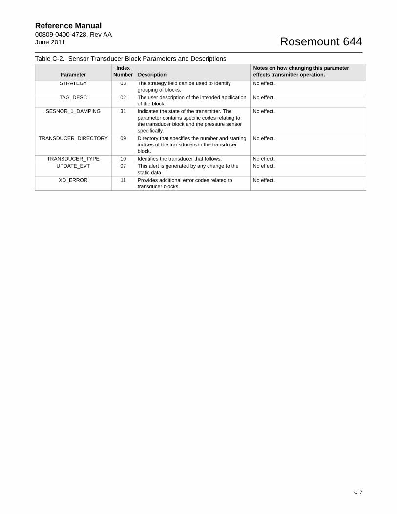
Reference Manual00809-0400-4728, Rev AAJune 2011 Rosemount 644
STRATEGY 03 The strategy field can be used to identify grouping of blocks.
No effect.
TAG_DESC 02 The user description of the intended application of the block.
No effect.
SESNOR_1_DAMPING 31 Indicates the state of the transmitter. The parameter contains specific codes relating to the transducer block and the pressure sensor specifically.
No effect.
TRANSDUCER_DIRECTORY 09 Directory that specifies the number and starting indices of the transducers in the transducer block.
No effect.
TRANSDUCER_TYPE 10 Identifies the transducer that follows. No effect.
UPDATE_EVT 07 This alert is generated by any change to the static data.
No effect.
XD_ERROR 11 Provides additional error codes related to transducer blocks.
No effect.
Table C-2. Sensor Transducer Block Parameters and Descriptions
ParameterIndex
Number DescriptionNotes on how changing this parameter effects transmitter operation.
C-7
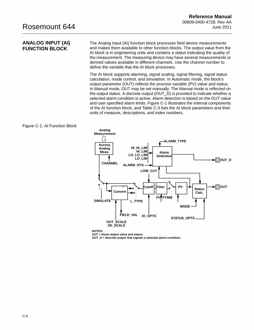
Reference Manual00809-0400-4728, Rev AA
June 2011Rosemount 644
ANALOG INPUT (AI) FUNCTION BLOCK
The Analog Input (AI) function block processes field device measurements and makes them available to other function blocks. The output value from the AI block is in engineering units and contains a status indicating the quality of the measurement. The measuring device may have several measurements or derived values available in different channels. Use the channel number to define the variable that the AI block processes.
The AI block supports alarming, signal scaling, signal filtering, signal status calculation, mode control, and simulation. In Automatic mode, the block’s output parameter (OUT) reflects the process variable (PV) value and status. In Manual mode, OUT may be set manually. The Manual mode is reflected on the output status. A discrete output (OUT_D) is provided to indicate whether a selected alarm condition is active. Alarm detection is based on the OUT value and user specified alarm limits. Figure C-1 illustrates the internal components of the AI function block, and Table C-3 lists the AI block parameters and their units of measure, descriptions, and index numbers.
Figure C-1. AI Function BlockAnalog
Measurement
AccessAnalogMeas.
CHANNEL
SIMULATE
OUT_SCALEXD_SCALE
FIELD_VAL
L_TYPE
IO_OPTS
PV_FTIME
MODE
STATUS_OPTS
HI_HI_LIMHI_LIM
LO_LO_LIMLO_LIM
ALARM_HYS
ALARM_TYPE
OUT_D
OUTPV
ConvertCutoff Filter
StatusCalc.
Alarm Detection
NOTES:OUT = block output value and status.OUT_D = discrete output that signals a selected alarm condition.
LOW_CUT
C-8
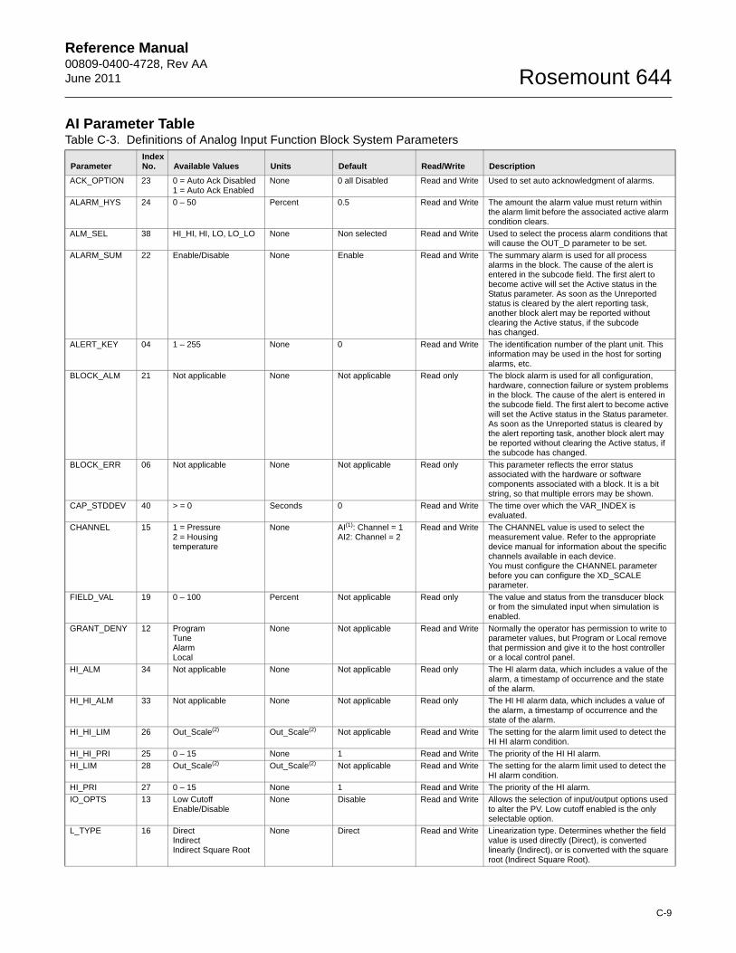
Reference Manual00809-0400-4728, Rev AAJune 2011 Rosemount 644
AI Parameter TableTable C-3. Definitions of Analog Input Function Block System Parameters
ParameterIndex No. Available Values Units Default Read/Write Description
ACK_OPTION 23 0 = Auto Ack Disabled1 = Auto Ack Enabled
None 0 all Disabled Read and Write Used to set auto acknowledgment of alarms.
ALARM_HYS 24 0 – 50 Percent 0.5 Read and Write The amount the alarm value must return within the alarm limit before the associated active alarm condition clears.
ALM_SEL 38 HI_HI, HI, LO, LO_LO None Non selected Read and Write Used to select the process alarm conditions that will cause the OUT_D parameter to be set.
ALARM_SUM 22 Enable/Disable None Enable Read and Write The summary alarm is used for all process alarms in the block. The cause of the alert is entered in the subcode field. The first alert to become active will set the Active status in the Status parameter. As soon as the Unreported status is cleared by the alert reporting task, another block alert may be reported without clearing the Active status, if the subcode has changed.
ALERT_KEY 04 1 – 255 None 0 Read and Write The identification number of the plant unit. This information may be used in the host for sorting alarms, etc.
BLOCK_ALM 21 Not applicable None Not applicable Read only The block alarm is used for all configuration, hardware, connection failure or system problems in the block. The cause of the alert is entered in the subcode field. The first alert to become active will set the Active status in the Status parameter. As soon as the Unreported status is cleared by the alert reporting task, another block alert may be reported without clearing the Active status, if the subcode has changed.
BLOCK_ERR 06 Not applicable None Not applicable Read only This parameter reflects the error status associated with the hardware or software components associated with a block. It is a bit string, so that multiple errors may be shown.
CAP_STDDEV 40 > = 0 Seconds 0 Read and Write The time over which the VAR_INDEX is evaluated.
CHANNEL 15 1 = Pressure2 = Housing temperature
None AI(1): Channel = 1 AI2: Channel = 2
Read and Write The CHANNEL value is used to select the measurement value. Refer to the appropriate device manual for information about the specific channels available in each device.You must configure the CHANNEL parameter before you can configure the XD_SCALE parameter.
FIELD_VAL 19 0 – 100 Percent Not applicable Read only The value and status from the transducer block or from the simulated input when simulation is enabled.
GRANT_DENY 12 ProgramTuneAlarmLocal
None Not applicable Read and Write Normally the operator has permission to write to parameter values, but Program or Local remove that permission and give it to the host controller or a local control panel.
HI_ALM 34 Not applicable None Not applicable Read only The HI alarm data, which includes a value of the alarm, a timestamp of occurrence and the state of the alarm.
HI_HI_ALM 33 Not applicable None Not applicable Read only The HI HI alarm data, which includes a value of the alarm, a timestamp of occurrence and the state of the alarm.
HI_HI_LIM 26 Out_Scale(2) Out_Scale(2) Not applicable Read and Write The setting for the alarm limit used to detect the HI HI alarm condition.
HI_HI_PRI 25 0 – 15 None 1 Read and Write The priority of the HI HI alarm.
HI_LIM 28 Out_Scale(2) Out_Scale(2) Not applicable Read and Write The setting for the alarm limit used to detect the HI alarm condition.
HI_PRI 27 0 – 15 None 1 Read and Write The priority of the HI alarm.
IO_OPTS 13 Low Cutoff Enable/Disable
None Disable Read and Write Allows the selection of input/output options used to alter the PV. Low cutoff enabled is the only selectable option.
L_TYPE 16 DirectIndirectIndirect Square Root
None Direct Read and Write Linearization type. Determines whether the field value is used directly (Direct), is converted linearly (Indirect), or is converted with the square root (Indirect Square Root).
C-9
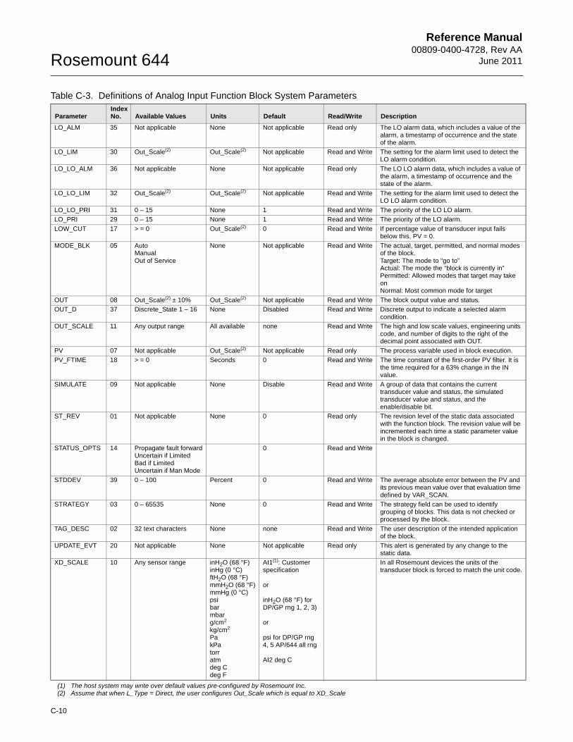
Reference Manual00809-0400-4728, Rev AA
June 2011Rosemount 644
C-10
LO_ALM 35 Not applicable None Not applicable Read only The LO alarm data, which includes a value of the alarm, a timestamp of occurrence and the state of the alarm.
LO_LIM 30 Out_Scale(2) Out_Scale(2) Not applicable Read and Write The setting for the alarm limit used to detect the LO alarm condition.
LO_LO_ALM 36 Not applicable None Not applicable Read only The LO LO alarm data, which includes a value of the alarm, a timestamp of occurrence and the state of the alarm.
LO_LO_LIM 32 Out_Scale(2) Out_Scale(2) Not applicable Read and Write The setting for the alarm limit used to detect the LO LO alarm condition.
LO_LO_PRI 31 0 – 15 None 1 Read and Write The priority of the LO LO alarm.
LO_PRI 29 0 – 15 None 1 Read and Write The priority of the LO alarm.
LOW_CUT 17 > = 0 Out_Scale(2) 0 Read and Write If percentage value of transducer input fails below this, PV = 0.
MODE_BLK 05 AutoManualOut of Service
None Not applicable Read and Write The actual, target, permitted, and normal modes of the block. Target: The mode to “go to”Actual: The mode the “block is currently in”Permitted: Allowed modes that target may take onNormal: Most common mode for target
OUT 08 Out_Scale(2) ± 10% Out_Scale(2) Not applicable Read and Write The block output value and status.
OUT_D 37 Discrete_State 1 – 16 None Disabled Read and Write Discrete output to indicate a selected alarm condition.
OUT_SCALE 11 Any output range All available none Read and Write The high and low scale values, engineering units code, and number of digits to the right of the decimal point associated with OUT.
PV 07 Not applicable Out_Scale(2) Not applicable Read only The process variable used in block execution.
PV_FTIME 18 > = 0 Seconds 0 Read and Write The time constant of the first-order PV filter. It is the time required for a 63% change in the IN value.
SIMULATE 09 Not applicable None Disable Read and Write A group of data that contains the current transducer value and status, the simulated transducer value and status, and the enable/disable bit.
ST_REV 01 Not applicable None 0 Read only The revision level of the static data associated with the function block. The revision value will be incremented each time a static parameter value in the block is changed.
STATUS_OPTS 14 Propagate fault forwardUncertain if LimitedBad if LimitedUncertain if Man Mode
0 Read and Write
STDDEV 39 0 – 100 Percent 0 Read and Write The average absolute error between the PV and its previous mean value over that evaluation time defined by VAR_SCAN.
STRATEGY 03 0 – 65535 None 0 Read and Write The strategy field can be used to identify grouping of blocks. This data is not checked or processed by the block.
TAG_DESC 02 32 text characters None none Read and Write The user description of the intended application of the block.
UPDATE_EVT 20 Not applicable None Not applicable Read only This alert is generated by any change to the static data.
XD_SCALE 10 Any sensor range inH2O (68 °F)inHg (0 °C)ftH2O (68 °F)mmH2O (68 °F)mmHg (0 °C)psibarmbarg/cm2
kg/cm2
PakPatorratm deg Cdeg F
AI1(1): Customer specification
or
inH2O (68 °F) for DP/GP rng 1, 2, 3)
or
psi for DP/GP rng 4, 5 AP/644 all rng
AI2 deg C
In all Rosemount devices the units of the transducer block is forced to match the unit code.
(1) The host system may write over default values pre-configured by Rosemount Inc.(2) Assume that when L_Type = Direct, the user configures Out_Scale which is equal to XD_Scale
Table C-3. Definitions of Analog Input Function Block System Parameters
ParameterIndex No. Available Values Units Default Read/Write Description
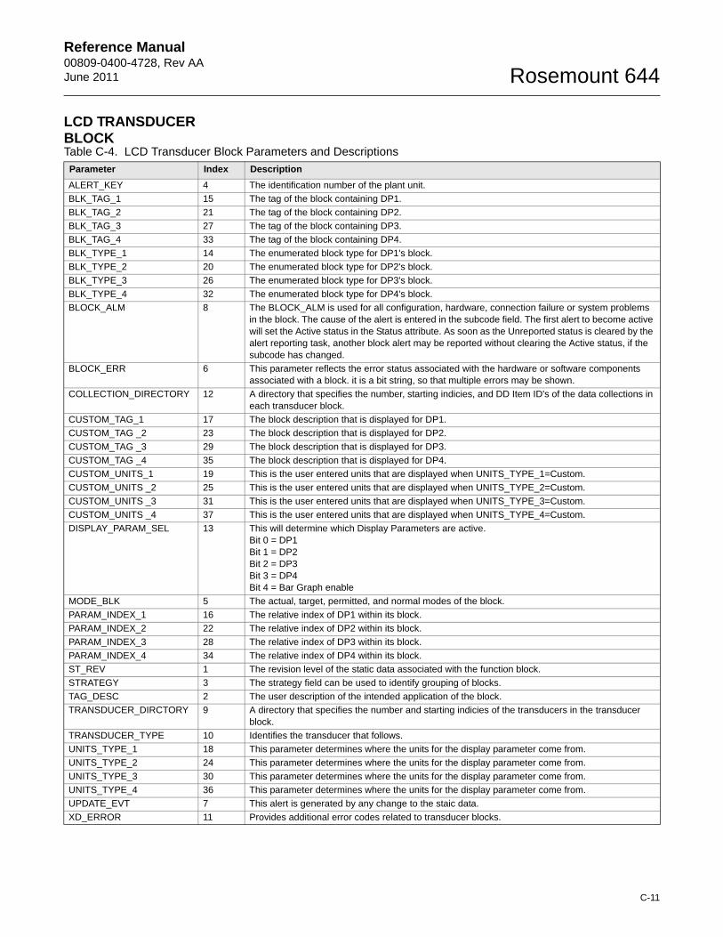
Reference Manual00809-0400-4728, Rev AAJune 2011 Rosemount 644
LCD TRANSDUCER BLOCKTable C-4. LCD Transducer Block Parameters and Descriptions
Parameter Index Description
ALERT_KEY 4 The identification number of the plant unit.
BLK_TAG_1 15 The tag of the block containing DP1.
BLK_TAG_2 21 The tag of the block containing DP2.
BLK_TAG_3 27 The tag of the block containing DP3.
BLK_TAG_4 33 The tag of the block containing DP4.
BLK_TYPE_1 14 The enumerated block type for DP1's block.
BLK_TYPE_2 20 The enumerated block type for DP2's block.
BLK_TYPE_3 26 The enumerated block type for DP3's block.
BLK_TYPE_4 32 The enumerated block type for DP4's block.
BLOCK_ALM 8 The BLOCK_ALM is used for all configuration, hardware, connection failure or system problems in the block. The cause of the alert is entered in the subcode field. The first alert to become active will set the Active status in the Status attribute. As soon as the Unreported status is cleared by the alert reporting task, another block alert may be reported without clearing the Active status, if the subcode has changed.
BLOCK_ERR 6 This parameter reflects the error status associated with the hardware or software components associated with a block. it is a bit string, so that multiple errors may be shown.
COLLECTION_DIRECTORY 12 A directory that specifies the number, starting indicies, and DD Item ID's of the data collections in each transducer block.
CUSTOM_TAG_1 17 The block description that is displayed for DP1.
CUSTOM_TAG _2 23 The block description that is displayed for DP2.
CUSTOM_TAG _3 29 The block description that is displayed for DP3.
CUSTOM_TAG _4 35 The block description that is displayed for DP4.
CUSTOM_UNITS_1 19 This is the user entered units that are displayed when UNITS_TYPE_1=Custom.
CUSTOM_UNITS _2 25 This is the user entered units that are displayed when UNITS_TYPE_2=Custom.
CUSTOM_UNITS _3 31 This is the user entered units that are displayed when UNITS_TYPE_3=Custom.
CUSTOM_UNITS _4 37 This is the user entered units that are displayed when UNITS_TYPE_4=Custom.
DISPLAY_PARAM_SEL 13 This will determine which Display Parameters are active.Bit 0 = DP1Bit 1 = DP2Bit 2 = DP3Bit 3 = DP4Bit 4 = Bar Graph enable
MODE_BLK 5 The actual, target, permitted, and normal modes of the block.
PARAM_INDEX_1 16 The relative index of DP1 within its block.
PARAM_INDEX_2 22 The relative index of DP2 within its block.
PARAM_INDEX_3 28 The relative index of DP3 within its block.
PARAM_INDEX_4 34 The relative index of DP4 within its block.
ST_REV 1 The revision level of the static data associated with the function block.
STRATEGY 3 The strategy field can be used to identify grouping of blocks.
TAG_DESC 2 The user description of the intended application of the block.
TRANSDUCER_DIRCTORY 9 A directory that specifies the number and starting indicies of the transducers in the transducer block.
TRANSDUCER_TYPE 10 Identifies the transducer that follows.
UNITS_TYPE_1 18 This parameter determines where the units for the display parameter come from.
UNITS_TYPE_2 24 This parameter determines where the units for the display parameter come from.
UNITS_TYPE_3 30 This parameter determines where the units for the display parameter come from.
UNITS_TYPE_4 36 This parameter determines where the units for the display parameter come from.
UPDATE_EVT 7 This alert is generated by any change to the staic data.
XD_ERROR 11 Provides additional error codes related to transducer blocks.
C-11
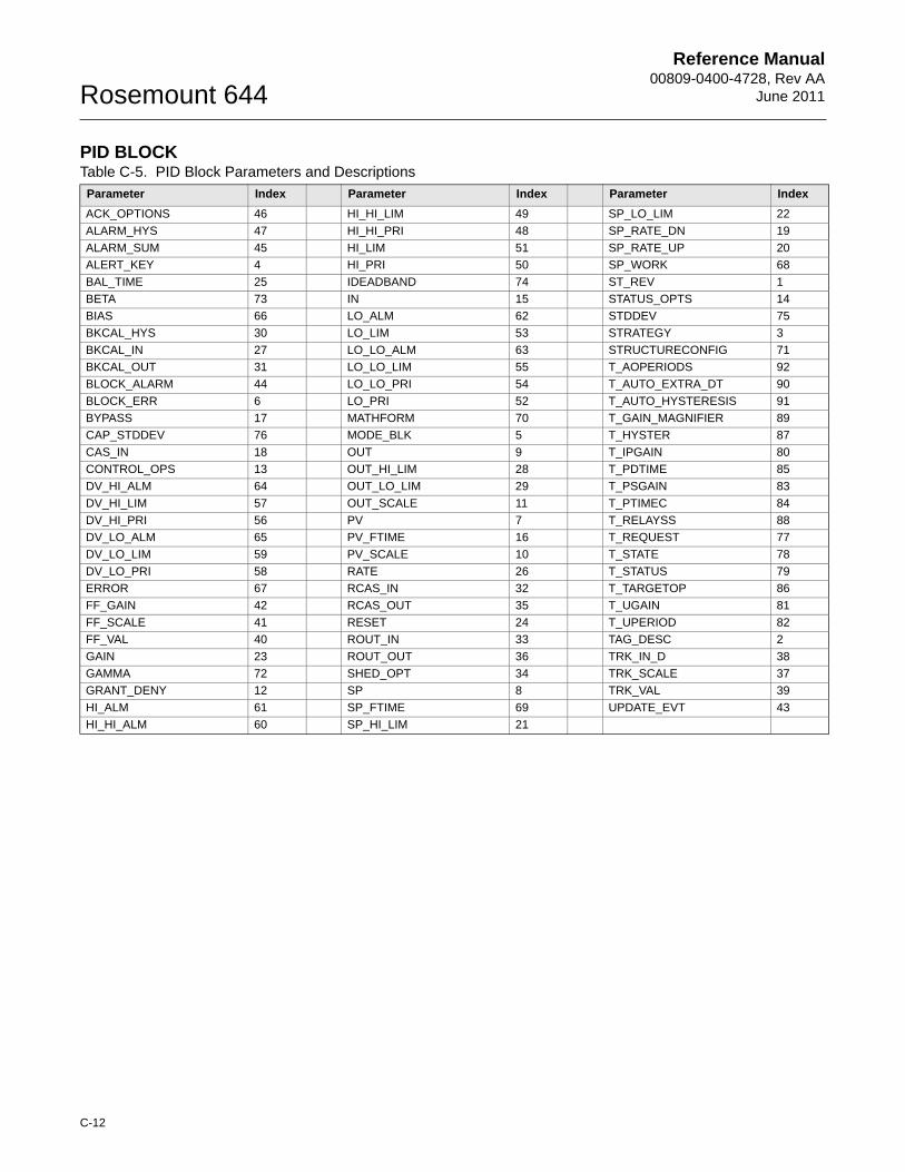
Reference Manual00809-0400-4728, Rev AA
June 2011Rosemount 644
PID BLOCKTable C-5. PID Block Parameters and Descriptions
Parameter Index Parameter Index Parameter Index
ACK_OPTIONS 46 HI_HI_LIM 49 SP_LO_LIM 22
ALARM_HYS 47 HI_HI_PRI 48 SP_RATE_DN 19
ALARM_SUM 45 HI_LIM 51 SP_RATE_UP 20
ALERT_KEY 4 HI_PRI 50 SP_WORK 68
BAL_TIME 25 IDEADBAND 74 ST_REV 1
BETA 73 IN 15 STATUS_OPTS 14
BIAS 66 LO_ALM 62 STDDEV 75
BKCAL_HYS 30 LO_LIM 53 STRATEGY 3
BKCAL_IN 27 LO_LO_ALM 63 STRUCTURECONFIG 71
BKCAL_OUT 31 LO_LO_LIM 55 T_AOPERIODS 92
BLOCK_ALARM 44 LO_LO_PRI 54 T_AUTO_EXTRA_DT 90
BLOCK_ERR 6 LO_PRI 52 T_AUTO_HYSTERESIS 91
BYPASS 17 MATHFORM 70 T_GAIN_MAGNIFIER 89
CAP_STDDEV 76 MODE_BLK 5 T_HYSTER 87
CAS_IN 18 OUT 9 T_IPGAIN 80
CONTROL_OPS 13 OUT_HI_LIM 28 T_PDTIME 85
DV_HI_ALM 64 OUT_LO_LIM 29 T_PSGAIN 83
DV_HI_LIM 57 OUT_SCALE 11 T_PTIMEC 84
DV_HI_PRI 56 PV 7 T_RELAYSS 88
DV_LO_ALM 65 PV_FTIME 16 T_REQUEST 77
DV_LO_LIM 59 PV_SCALE 10 T_STATE 78
DV_LO_PRI 58 RATE 26 T_STATUS 79
ERROR 67 RCAS_IN 32 T_TARGETOP 86
FF_GAIN 42 RCAS_OUT 35 T_UGAIN 81
FF_SCALE 41 RESET 24 T_UPERIOD 82
FF_VAL 40 ROUT_IN 33 TAG_DESC 2
GAIN 23 ROUT_OUT 36 TRK_IN_D 38
GAMMA 72 SHED_OPT 34 TRK_SCALE 37
GRANT_DENY 12 SP 8 TRK_VAL 39
HI_ALM 61 SP_FTIME 69 UPDATE_EVT 43
HI_HI_ALM 60 SP_HI_LIM 21
C-12
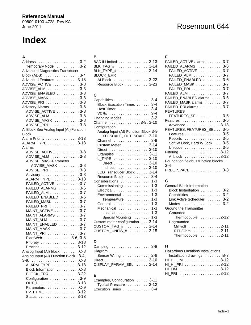
Reference Manual 00809-0100-4728, Rev KAJune 2011 Rosemount 644
Index
AAddress . . . . . . . . . . . . . . . . . . 3-2
Temporary Node . . . . . . . . . . 3-2Advanced Diagnostics Transducer Block (ADB) . . . . . . . . . . . . . . . 3-4Advanced Features . . . . . . . . . 3-13ADVISE_ACTIVE . . . . . . . . . . . . 3-8ADVISE_ALM . . . . . . . . . . . . . . 3-8ADVISE_ENABLED . . . . . . . . . . 3-8ADVISE_MASK . . . . . . . . . . . . . 3-8ADVISE_PRI . . . . . . . . . . . . . . . 3-8Advisory Alarms . . . . . . . . . . . . . 3-8
ADVISE_ACTIVE . . . . . . . . . . 3-8ADVISE_ALM . . . . . . . . . . . . 3-8ADVISE_MASK . . . . . . . . . . . 3-8ADVISE_PRI . . . . . . . . . . . . . 3-8
AI Block.See Analog Input (AI) Function BlockAlarm Priority . . . . . . . . . . . . . . 3-13ALARM_TYPE . . . . . . . . . . . . . 3-13Alarms
ADVISE_ACTIVE . . . . . . . . . . 3-8ADVISE_ALM . . . . . . . . . . . . 3-8ADVISE_MASKParameter
ADVISE_MASK . . . . . . . . . 3-8ADVISE_PRI . . . . . . . . . . . . . 3-8Advisory . . . . . . . . . . . . . . . . 3-8ALARM_TYPE . . . . . . . . . . . 3-13FAILED_ACTIVE . . . . . . . . . . 3-7FAILED_ALARMS . . . . . . . . . 3-6FAILED_ALM . . . . . . . . . . . . . 3-7FAILED_ENABLED . . . . . . . . 3-6FAILED_MASK . . . . . . . . . . . 3-7FAILED_PRI . . . . . . . . . . . . . 3-7MAINT_ACTIVE . . . . . . . . . . . 3-7MAINT_ALARMS . . . . . . . . . . 3-7MAINT_ALM . . . . . . . . . . . . . 3-7MAINT_ENABLED . . . . . . . . . 3-7MAINT_MASK . . . . . . . . . . . . 3-7MAINT_PRI . . . . . . . . . . . . . . 3-7PlantWeb . . . . . . . . . . . . 3-6, 3-8Priorety . . . . . . . . . . . . . . . . 3-13Process . . . . . . . . . . . . . . . . 3-12
Analog Input (AI) block . . . . . . . .C-8Analog Input (AI) Function Block 3-4, 3-9, . . . . . . . . . . . . . . . . . . . . .C-8
ALARM_TYPE . . . . . . . . . . . 3-13Block Information . . . . . . . . . .C-8BLOCK_ERR . . . . . . . . . . . . 3-22Configuration . . . . . . . . . . . . . 3-9OUT_D . . . . . . . . . . . . . . . . 3-13Parameters . . . . . . . . . . . . . .C-9PV_FTIME . . . . . . . . . . . . . . 3-12Status . . . . . . . . . . . . . . . . . 3-13
BBAD if Limited . . . . . . . . . . . . . 3-13BLK_TAG_# . . . . . . . . . . . . . . 3-14BLK_TYPE_# . . . . . . . . . . . . . 3-14BLOCK_ERR
AI Block . . . . . . . . . . . . . . . 3-22Resource Block . . . . . . . . . . 3-23
CCapabilities . . . . . . . . . . . . . . . . 3-4
Block Execution Times . . . . . . 3-4Host Timer . . . . . . . . . . . . . . 3-4VCRs . . . . . . . . . . . . . . . . . . 3-4
Changing Modes . . . . . . . . . . . . 3-2Channel . . . . . . . . . . . . . .3-9, 3-10Configuration
Analog Input (AI) Function Block 3-9XD_SCALE, OUT_SCALE 3-10
Channel . . . . . . . . . . . . . . . . 3-9Custom Meter . . . . . . . . . . . 3-14Direct . . . . . . . . . . . . . . . . . 3-10Examples . . . . . . . . . . . . . . 3-11L_TYPE . . . . . . . . . . . . . . . 3-10
Direct . . . . . . . . . . . . . . . 3-10Indirect . . . . . . . . . . . . . . 3-10
LCD Transducer Block . . . . . 3-14Resource Block . . . . . . . . . . . 3-4
Considerations . . . . . . . . . . . . . 1-3Commissioning . . . . . . . . . . . 1-3Electrical . . . . . . . . . . . . . . . . 1-3Environmental . . . . . . . . . . . . 1-3
Temperature . . . . . . . . . . . 1-3General . . . . . . . . . . . . . . . . 1-3Mechanical . . . . . . . . . . . . . . 1-3
Location . . . . . . . . . . . . . . 1-3Special Mounting . . . . . . . . 1-3
Custom meter configuration . . . 3-14CUSTOM_TAG_# . . . . . . . . . . 3-14CUSTOM_UNITS_# . . . . . . . . 3-15
DDamping . . . . . . . . . . . . . . . . . 3-9Diagram
Sensor Wiring . . . . . . . . . . . . 2-8Direct . . . . . . . . . . . . . . . . . . . 3-10DISPLAY_PARAM_SEL . . . . . 3-14
EExamples, Configuration . . . . . 3-11
Typical Pressure . . . . . . . . . 3-12Execution Times . . . . . . . . . . . . 3-4
FFAILED_ACTIVE alarms . . . . . . .3-7FAILED_ALARMS . . . . . . . . . . .3-6
FAILED_ACTIVE . . . . . . . . . . .3-7FAILED_ALM . . . . . . . . . . . . .3-7FAILED_ENABLED . . . . . . . . .3-6FAILED_MASK . . . . . . . . . . . .3-7FAILED_PRI . . . . . . . . . . . . . .3-7
FAILED_ALM . . . . . . . . . . . . . . .3-7FAILED_ENABLED alarms . . . . .3-6FAILED_MASK alarms . . . . . . . .3-7FAILED_PRI alarms . . . . . . . . . .3-7FEATURES
FEATURES_SEL . . . . . . . . . .3-6Features . . . . . . . . . . . . . . . . . .3-5
Advanced . . . . . . . . . . . . . . .3-13FEATURES, FEATURES_SEL . . .3-5
Features . . . . . . . . . . . . . . . . .3-5Reports . . . . . . . . . . . . . . . . .3-5Soft W Lock, Hard W Lock . . . .3-5Unicode . . . . . . . . . . . . . . . . .3-5
Filtering . . . . . . . . . . . . . . . . . .3-12AI block . . . . . . . . . . . . . . . .3-12
Foundation fieldbus function blocks . 3-4FREE_SPACE . . . . . . . . . . . . . .3-3
GGeneral Block Information
Block Instantiation . . . . . . . . . .3-2Capabilities . . . . . . . . . . . . . . .3-2Link Active Scheduler . . . . . . .3-2Modes . . . . . . . . . . . . . . . . . .3-2
Ground the TransmitterGrounded
Thermocouple . . . . . . . . .2-12Ungrounded
Millivolt . . . . . . . . . . . . . . 2-11RTD/Ohm . . . . . . . . . . . . 2-11Thermocouple . . . . . . . . . 2-11
HHazardous Locations Installations
Installation drawings . . . . . . . B-7HI_HI_LIM . . . . . . . . . . . . . . . .3-12HI_HI_PRI . . . . . . . . . . . . . . . .3-12HI_LIM . . . . . . . . . . . . . . . . . .3-12HI_PRI . . . . . . . . . . . . . . . . . .3-12
Index-1
Reference Manual00809-0100-4728, Rev KA
June 2011Rosemount 644
IIndirect . . . . . . . . . . . . . . . . . . 3-10Installation . . . . . . . . . . . . . . . . . 2-4
European . . . . . . . . . . . . . . . . 2-4Head Mount . . . . . . . . . . . . 2-4
Flowchart . . . . . . . . . . . . . . . . 2-2LCD Display . . . . . . . . . . . . . . 2-6Multichannel . . . . . . . . . . . . . 2-7North American . . . . . . . . . . . 2-5
Head Mount . . . . . . . . . . . . 2-5Rail Mount . . . . . . . . . . . . . 2-6
Instantiation, Block . . . . . . . . . . . 3-3
LL_TYPE . . . . . . . . . . . . . . . . . 3-10
Direct . . . . . . . . . . . . . . . . . 3-10Indirect . . . . . . . . . . . . . . . . 3-10
LCD DisplayInstallation . . . . . . . . . . . . . . . 2-6
LCD meter . . . . . . . . . . . . . . . 3-14LCD Transducer Block . . . 3-4, 3-14, C-11
Messaging . . . . . . . . . . . . . . 3-14Parameters . . . . . . . . . . . . . C-11
LCD Transducer block . . . . . . . 3-24Block Error . . . . . . . . . . . . . . 3-24Self Test . . . . . . . . . . . . . . . 3-24
LIM_NOTIFY . . . . . . . . . . . . . . . 3-6Limited
Bad . . . . . . . . . . . . . . . . . . . 3-13Uncertain . . . . . . . . . . . . . . . 3-13
Link Active Scheduler . . . . . . . . . 3-3LO_LIM . . . . . . . . . . . . . . . . . 3-12LO_LO_LIM . . . . . . . . . . . . . . 3-12LO_LO_PRI . . . . . . . . . . . . . . 3-12LO_PRI . . . . . . . . . . . . . . . . . 3-12Lower Trim Method . . . . . . . . . 3-18
MMAINT_ACTIVE . . . . . . . . . . . . 3-7MAINT_ALARMS . . . . . . . . . . . . 3-7
MAINT_ACTIVE . . . . . . . . . . . 3-7MAINT_ALM . . . . . . . . . . . . . 3-7MAINT_ENABLED . . . . . . . . . 3-7MAINT_MASK . . . . . . . . . . . . 3-7MAINT_PRI . . . . . . . . . . . . . . 3-7
MAINT_ALM . . . . . . . . . . . . . . . 3-7MAINT_ENABLED . . . . . . . . . . . 3-7MAINT_MASK . . . . . . . . . . . . . . 3-7MAINT_PRI . . . . . . . . . . . . . . . . 3-7Manual Mode . . . . . . . . . . . . . 3-21Manual Operation . . . . . . . . . . 3-15MAX_NOTIFY . . . . . . . . . . . . . . 3-6
LIM_NOTIFY . . . . . . . . . . . . . 3-6Methods . . . . . . . . . . . . . . . . . 3-15
MillivoltUngrounded . . . . . . . . . . . . 2-11Wiring . . . . . . . . . . . . . . . . . . 2-8
MODE_BLK.TARGET . . . . . . . . 3-2MODE_BLOCK.ACTUAL . . . . . . 3-2Modes
Changing Modes . . . . . . . . . . 3-2Permitted Modes . . . . . . . . . . 3-2Types of Modes . . . . . . . . . . . 3-2
Auto . . . . . . . . . . . . . . . . . 3-2Man . . . . . . . . . . . . . . . . . 3-2Other . . . . . . . . . . . . . . . . 3-2Out of Service . . . . . . . . . . 3-2
Mounting . . . . . . . . . . . . . . . . . 2-3Model 644H
DIN Rail . . . . . . . . . . . . . . 2-3Threaded Sensor . . . . . . . . 2-3
MultichannelInstallation . . . . . . . . . . . . . . . 2-7
NNetwork Parameters . . . . . . . . . 3-4Node address . . . . . . . . . . . . . . 3-2
OOhm
Ungrounded . . . . . . . . . . . . 2-11Wiring . . . . . . . . . . . . . . . . . . 2-9
Operation and MaintenanceSensor Transducer Block . . . 3-18
OUT_D . . . . . . . . . . . . . . . . . 3-13AI block . . . . . . . . . . . . . . . 3-13
Overview . . . . . . . . . . . . . . . . . 1-2Manual . . . . . . . . . . . . . . . . . 1-2Transmitter . . . . . . . . . . . . . . 1-2
PPARAM_INDEX_# . . . . . . . . . . 3-14Parameter
ADVISE_ACTIVE . . . . . . . . . . 3-8ADVISE_ALM . . . . . . . . . . . . 3-8ADVISE_ENABLED . . . . . . . . 3-8ADVISE_PRI . . . . . . . . . . . . . 3-8ALARM_TYPE . . . . . . . . . . . 3-13Analog Input (AI) Function Block . .
C-9BLK_TAG_# . . . . . . . . . . . . 3-14BLK_TYPE_# . . . . . . . . . . . 3-14BLOCK_ERR . . . . . . .3-22, 3-23CHANNEL . . . . . . . . . . . . . . . 3-9CUSTOM_TAG_# . . . . . . . . 3-14CUSTOM_UNITS_# . . . . . . . 3-15DEFINE_WRITE_LOCK . . . . . 3-5DISPLAY_PARAM_SEL . . . . 3-14FAILED_ACTIVE . . . . . . . . . . 3-7FAILED_ALARMS . . . . . . . . . 3-6
FAILED_ALM . . . . . . . . . . . . .3-7FAILED_ENABLED . . . . . . . . .3-6FAILED_MASK . . . . . . . . . . . .3-7FAILED_PRI . . . . . . . . . . . . . .3-7FEATURES . . . . . . . . . . . . . .3-5FEATURES_SEL . . . . . . . . . .3-6FREE_SPACE . . . . . . . . . . . .3-3HI_HI_LIM . . . . . . . . . . . . . .3-12HI_HI_PRI . . . . . . . . . . . . . .3-12HI_LIM . . . . . . . . . . . . . . . . .3-12HI_PRI . . . . . . . . . . . . . . . . .3-12L_TYPE . . . . . . . . . . . . . . . .3-10LCD Transducer Block . . . . . C-11LIM_NOTIFY . . . . . . . . . . . . .3-6LO_LIM . . . . . . . . . . . . . . . .3-12LO_LO_LIM . . . . . . . . . . . . .3-12LO_LO_PRI . . . . . . . . . . . . .3-12LO_PRI . . . . . . . . . . . . . . . .3-12MAINT_ACTIVE . . . . . . . . . . .3-7MAINT_ALARMS . . . . . . . . . .3-7MAINT_ALM . . . . . . . . . . . . . .3-7MAINT_ENABLED . . . . . . . . .3-7MAINT_MASK . . . . . . . . . . . .3-7MAINT_PRI . . . . . . . . . . . . . .3-7MAX_NOTIFY . . . . . . . . . . . . .3-6MODE_BLK.TARGET . . . . . . .3-2MODE_BLOCK_ACTUAL . . . .3-2Network . . . . . . . . . . . . . . . . .3-4OUT_D . . . . . . . . . . . . . . . .3-13OUT_SCALE . . . . . . . . . . . .3-10PARAM_INDEX_# . . . . . . . . .3-14PV_FTIME . . . . . . . . . . 3-9, 3-12RECOMMENDED_ACTION . . .3-8REPORTS . . . . . . . . . . . . . . .3-5Resource Block . . . . . . . . . . . C-2Sensor Transducer Block . . . . C-5STATUS_OPTIONS . . . . . . .3-13UNICODE . . . . . . . . . . . . . . .3-5UNITS_TYPE_# . . . . . . . . . .3-15WRITE_LOCK . . . . . . . . . . . .3-5XD_SCALE . . . . . . . . . 3-9, 3-10
Performance specifications . . . . A-3Permitted Modes . . . . . . . . . . . .3-2PID Block . . . . . . . . . . . . . . . . . .3-4PID block . . . . . . . . . . . . . . . . . .3-4PlantWeb Alarms . . . . . . . . 3-6, 3-8
Advisory . . . . . . . . . . . . . . . . .3-8FAILED_ALARMS . . . . . . . . . .3-6MAINT_ALARMS . . . . . . . . . .3-7
Power Supply . . . . . . . . . . . . . . 2-11Process Alarms . . . . . . . . . . . .3-12Propagate Fault Forward . . . . . .3-13Proportional/Integral/Derivative (PID) function block . . . . . . . . . . . . . . .3-4PV_FTIME . . . . . . . . . . . . . . . . .3-9
AI block . . . . . . . . . . . . . . . .3-12
Index-2
Reference Manual 00809-0100-4728, Rev KAJune 2011 Rosemount 644
RRecommended Actions . . . . . . . . 3-8
PlantWeb Alarms . . . . . . . . . . 3-8RECOMMENDED_ACTION . . . . 3-8Reference data . . . . . . . . . . . . . A-8Reports . . . . . . . . . . . . . . . . . . . 3-5Resource Block . . . . 3-4, 3-23, C-1
Block Errors . . . . . . . . . . . . . 3-23Block Information . . . . . . . . . .C-1Configuration . . . . . . . . . . . . . 3-4Detailed Status . . . . . . . . . . . 3-23FEATURES, FEATURES_SEL 3-5Parameters . . . . . . . . . . . . . .C-2
BLOCK_ERR . . . . . . . . . . 3-23Summary Status . . . . . . . . . . 3-23
Resource block . . . . . . . . . . . . .C-1Return of Materials . . . . . . . . . . . 1-4RTD
Ungrounded . . . . . . . . . . . . . 2-11Wiring . . . . . . . . . . . . . . . . . . 2-9
SSecurity . . . . . . . . . . . . . . . . . . 3-5Self Test . . . . . . . . . . . . . . . . . 3-24Sensor
ConnectionDiagram . . . . . . . . . . . . . . 2-8
Millivolt . . . . . . . . . . . . . . . . . 2-8Ohm . . . . . . . . . . . . . . . . . . . 2-9RTD . . . . . . . . . . . . . . . . . . . 2-9Thermocouple . . . . . . . . . . . . 2-8Wiring . . . . . . . . . . . . . . . . . . 2-8
Sensor Calibration . . . . . . . . . . 3-18Sensor Transducer Block . . 3-4, 3-9, 3-18, . . . . . . . . . . . . . . . . . . . .C-5
Block Information . . . . . . . . . .C-5Configuration . . . . . . . . . . . . . 3-9Operation and Maintenance . . 3-18Parameters . . . . . . . . . . . . . .C-5
Simulate . . . . . . . . . . . . . . . . . 3-21Simulation . . . . . . . . . . . . . . . . 3-21
Manual Mode . . . . . . . . . . . . 3-21Soft W Lock, Hard W Lock . . . . . 3-5Specifications
Performance . . . . . . . . . . . . . A-3Status . . . . . . . . . . . . . . . . . . . 3-21
AI block . . . . . . . . . . . . . . . . 3-13STATUS_OPTIONS . . . . . . . . . 3-13Supported Units . . . . . . . . . . . . 3-10Switches
Simulate . . . . . . . . . . . . . . . 3-21
TThermocouple
Grounded . . . . . . . . . . . . . . 2-12Ungrounded . . . . . . . . . . . . . 2-11Wiring . . . . . . . . . . . . . . . . . . 2-8
TrimZero . . . . . . . . . . . . . . . . . . . 3-9
Troubleshooting . . . . . . . . . . . 3-16Flowchart . . . . . . . . . . . . . . 3-16LCD Transducer block . . . . . 3-24Reference table . . . . . . . . . . 3-16Resource Block . . . . . . . . . . 3-23
Types of ModesAuto . . . . . . . . . . . . . . . . . . . 3-2Man . . . . . . . . . . . . . . . . . . . 3-2Other Types of Modes . . . . . . 3-2Out of Service . . . . . . . . . . . . 3-2
UUncertain
Limited . . . . . . . . . . . . . . . . 3-13Man Mode . . . . . . . . . . . . . . 3-13
Unicode . . . . . . . . . . . . . . . . . . 3-5UNITS_TYPE_# . . . . . . . . . . . 3-15Upper Trim Method . . . . . . . . . 3-18
VVirtual Communication Relationship (VCRs) . . . . . . . . . . . . . . . . . . . 3-4
Network Parameters . . . . . . . . 3-4
WWiring . . . . . . . . . . . . . . . . . . . 2-7
Sensor Connection . . . . . . . . 2-8Diagram . . . . . . . . . . . . . . 2-8Millivolt . . . . . . . . . . . . . . . 2-8Ohm . . . . . . . . . . . . . . . . . 2-9RTD . . . . . . . . . . . . . . . . . 2-9Thermocouple . . . . . . . . . . 2-8
XXD_SCALE . . . . . . . . . . . . . . . 3-9XD_SCALE, OUT_SCALE . . . . 3-10
L_TYPEDirect . . . . . . . . . . . . . . . 3-10
ZZero Trim . . . . . . . . . . . . . . . . . 3-9
Index-3

Reference Manual00809-0100-4728, Rev KA
June 2011Rosemount 644
Index-4


Reference Manual00809-0400-4728, Rev AA
June 2011
Emerson Process Management
00809-0400-4728 Rev AA, 6/11
Standard Terms and Conditions of Sale can be found at www.rosemount.com/terms_of_saleThe Emerson logo is a trademark and service mark of Emerson Electric Co.Rosemount and the Rosemount logotype are registered trademarks of Rosemount Inc. PlantWeb is a registered trademark of one of the Emerson Process Management group of companies.FOUNDATION is a trademark of the Fieldbus Foundation.HART is a registered trademark of the HART Communication Foundation.Lexan and Noryl are registered trademark of General Electric.WAGO is a registered trademark of Kontakttechnik GmbH, Germany.All other marks are the property of their respective owners.
© 2011 Rosemount Inc. All rights reserved.
Emerson Process Management Temperature GmbHFrankenstrasse 2163791 KarlsteinGermanyT 49 (6188) 992 0F 49 (6188) 992 112
Emerson Process Management Asia Pacific Private Limited1 Pandan CrescentSingapore 128461T (65) 6777 8211F (65) 6777 [email protected]
Rosemount Inc.8200 Market BoulevardChanhassen, MN 55317 USAT (U.S.) 1-800-999-9307T (International) (952) 906-8888F (952) 906-8889
www.rosemount.com