Embed Size (px)
Citation preview
www.rosemount.com
Reference Manual 00809-0100-4648, Rev BA
August 2007
Rosemount 648 Wireless Temperature
Transmitter
Product Discontinued

Reference Manual 00809-0100-4648, Rev BA
August 2007 Rosemount 648
www.rosemount.com
Rosemount 648 WirelessTemperature Transmitter
Rosemount 648 Wireless Temperature Transmitter may be protected by one or more U.S.
Patents pending. Other foreign patents pending.
Rosemount 648 Hardware Revision
HART® Device Revision
Field Communicator Field Device Revision
1
1
Dev v1, DD v4
NOTICE
Read this manual before working with the product. For personal and system safety, and for
optimum product performance, make sure to thoroughly understand the contents before
installing, using, or maintaining this product.
The United States has two toll-free assistance numbers and one international number.
Customer Central
1-800-999-9307 (7:00 a.m. to 7:00 P.M. CST)
National Response Center
1-800-654-7768 (24 hours a day)
Equipment service needs
International
1-(952) 906-8888
The products described in this document are NOT designed for nuclear-qualified
applications.
Using non-nuclear qualified products in applications that require nuclear-qualified hardware
or products may cause inaccurate readings.
For information on Rosemount nuclear-qualified products, contact a Emerson Process
Management Sales Representative.
Reference Manual00809-0100-4648, Rev BA
August 2007Rosemount 648
The battery pack with the wireless unit contains two “C” size primary lithium/thionyl chloride batteries. Each battery contains approximately 2.5 grams of lithium, for a total of 5 grams in each pack. Under normal conditions, the battery materials are self-contained and are not reactive as long as the batteries and the pack integrity are maintained. Care should be taken to prevent thermal, electrical or mechanical damage. Contacts should be protected to prevent premature discharge.
Battery hazards remain when cells are discharged.
Batteries should be stored in a clean and dry area. For maximum battery life, storage temperature should not exceed 30° C.
Explosions could result in death or serious injury:
Installation of this transmitter in an explosive environment must be in accordance
with the appropriate local, national, and international standards, codes, and
practices. Please review the approvals section of the 648 reference manual for any
restrictions associated with a safe installation.
• Before connecting a Field Communicator in an explosive atmosphere, ensure the
instruments are installed in accordance with intrinsically safe or non-incendive
field wiring practices.
Process leaks may cause harm or result in death.
• Install and tighten process connectors before applying pressure.
Electrical shock can result in death or serious injury.
• Avoid contact with the leads and terminals. High voltage that may be present on
leads can cause electrical shock.
NOTICE
The Rosemount 648 and all other wireless devices should be installed only after the
1420 Wireless Gateway has been installed and is functioning properly. Wireless devices
should also be powered up in order of proximity from the 1420 Wireless Gateway,
beginning with the closest. This will result in a simpler and faster network installation.
NOTICE
Shipping considerations for wireless products (Lithium Batteries):
The unit was shipped to you without the battery installed. Please remove the battery pack
from the unit prior to shipping.
Primary lithium batteries are regulated in transportation by the U. S. Department of
Transportation, and are also covered by IATA (International Air Transport Association),
ICAO (International Civil Aviation Organization), and ARD (European Ground
Transportation of Dangerous Goods). It is the responsibility of the shipper to ensure
compliance with these or any other local requirements. Please consult current regulations
and requirements before shipping.
Reference Manual 00809-0100-4648, Rev AA
August 2007
TOC-1
Rosemount 648
Table of Contents
Shipping considerations for wireless products (Lithium Batteries):.0-2
SECTION 1Overview
Safety Messages . . . . . . . . . . . . . . . . . . . . . . . . . . . . . . . . . . . . . . . . .1-1
Warnings. . . . . . . . . . . . . . . . . . . . . . . . . . . . . . . . . . . . . . . . . . . . .1-1
Overview . . . . . . . . . . . . . . . . . . . . . . . . . . . . . . . . . . . . . . . . . . . . . . .1-2
Manual . . . . . . . . . . . . . . . . . . . . . . . . . . . . . . . . . . . . . . . . . . . . . .1-2
Transmitter . . . . . . . . . . . . . . . . . . . . . . . . . . . . . . . . . . . . . . . . . . .1-2
Considerations . . . . . . . . . . . . . . . . . . . . . . . . . . . . . . . . . . . . . . . . . . .1-3
General . . . . . . . . . . . . . . . . . . . . . . . . . . . . . . . . . . . . . . . . . . . . . .1-3
Commissioning . . . . . . . . . . . . . . . . . . . . . . . . . . . . . . . . . . . . . . . .1-3
Mechanical . . . . . . . . . . . . . . . . . . . . . . . . . . . . . . . . . . . . . . . . . . .1-3
Electrical . . . . . . . . . . . . . . . . . . . . . . . . . . . . . . . . . . . . . . . . . . . . .1-3
Environmental . . . . . . . . . . . . . . . . . . . . . . . . . . . . . . . . . . . . . . . . .1-4
Return of Materials. . . . . . . . . . . . . . . . . . . . . . . . . . . . . . . . . . . . . . . .1-5
SECTION 2Configuration
Safety Messages . . . . . . . . . . . . . . . . . . . . . . . . . . . . . . . . . . . . . . . . .2-1
Warnings. . . . . . . . . . . . . . . . . . . . . . . . . . . . . . . . . . . . . . . . . . . . .2-1
Sensor Connections . . . . . . . . . . . . . . . . . . . . . . . . . . . . . . . . . . . .2-2
Device Sensor Configuration . . . . . . . . . . . . . . . . . . . . . . . . . . . . . . . .2-6
Device Network Configuration . . . . . . . . . . . . . . . . . . . . . . . . . . . . . . .2-6
HART Menu Tree . . . . . . . . . . . . . . . . . . . . . . . . . . . . . . . . . . . . . .2-8
Fast Key Sequence. . . . . . . . . . . . . . . . . . . . . . . . . . . . . . . . . . . . .2-9
Calibration. . . . . . . . . . . . . . . . . . . . . . . . . . . . . . . . . . . . . . . . . . . .2-9
Alerts. . . . . . . . . . . . . . . . . . . . . . . . . . . . . . . . . . . . . . . . . . . . . . .2-12
Remove Battery . . . . . . . . . . . . . . . . . . . . . . . . . . . . . . . . . . . . . . . . .2-13
SECTION 3Mounting
Safety Messages . . . . . . . . . . . . . . . . . . . . . . . . . . . . . . . . . . . . . . . . .3-1
Warnings. . . . . . . . . . . . . . . . . . . . . . . . . . . . . . . . . . . . . . . . . . . . .3-1
Mounting . . . . . . . . . . . . . . . . . . . . . . . . . . . . . . . . . . . . . . . . . . . . . . .3-2
Direct Mount . . . . . . . . . . . . . . . . . . . . . . . . . . . . . . . . . . . . . . . . . .3-2
Remote Mount . . . . . . . . . . . . . . . . . . . . . . . . . . . . . . . . . . . . . . . .3-4
LCD Display . . . . . . . . . . . . . . . . . . . . . . . . . . . . . . . . . . . . . . . . . .3-5
Ground the Transmitter . . . . . . . . . . . . . . . . . . . . . . . . . . . . . . . . . .3-5
SECTION 4Commissioning
Safety Messages . . . . . . . . . . . . . . . . . . . . . . . . . . . . . . . . . . . . . . . . .4-1
Warnings. . . . . . . . . . . . . . . . . . . . . . . . . . . . . . . . . . . . . . . . . . . . .4-1
Verify Operation . . . . . . . . . . . . . . . . . . . . . . . . . . . . . . . . . . . . . . . . . .4-2
SECTION 5Operation and Maintenance
Safety Messages . . . . . . . . . . . . . . . . . . . . . . . . . . . . . . . . . . . . . . . . .5-1
Warnings. . . . . . . . . . . . . . . . . . . . . . . . . . . . . . . . . . . . . . . . . . . . .5-1
LCD Screen Messages . . . . . . . . . . . . . . . . . . . . . . . . . . . . . . . . . . . .5-2
Startup Screen Sequence. . . . . . . . . . . . . . . . . . . . . . . . . . . . . . . .5-2
Diagnostic Button Screen Sequence . . . . . . . . . . . . . . . . . . . . . . .5-3
Network Diagnostic Status Screens . . . . . . . . . . . . . . . . . . . . . . . .5-4
Device Diagnostic Screens . . . . . . . . . . . . . . . . . . . . . . . . . . . . . . .5-6
Battery Replacement . . . . . . . . . . . . . . . . . . . . . . . . . . . . . . . . . . . . . .5-9
Reference Manual00809-0100-4648, Rev AA
August 2007Rosemount 648
TOC-2
APPENDIX ASpecifications and Reference Data
Specifications. . . . . . . . . . . . . . . . . . . . . . . . . . . . . . . . . . . . . . . . . . . .A-1
Functional Specifications . . . . . . . . . . . . . . . . . . . . . . . . . . . . . . . .A-1
Physical Specifications . . . . . . . . . . . . . . . . . . . . . . . . . . . . . . . . . .A-1
Performance Specifications . . . . . . . . . . . . . . . . . . . . . . . . . . . . . .A-2
Accuracy. . . . . . . . . . . . . . . . . . . . . . . . . . . . . . . . . . . . . . . . . . . . .A-3
Ambient Temperature Effect. . . . . . . . . . . . . . . . . . . . . . . . . . . . . .A-4
Dimensional Drawings . . . . . . . . . . . . . . . . . . . . . . . . . . . . . . . . . . . . .A-5
Ordering Information . . . . . . . . . . . . . . . . . . . . . . . . . . . . . . . . . . . . . .A-6
APPENDIX BProduct Certifications
Approved Manufacturing Locations . . . . . . . . . . . . . . . . . . . . . . . .B-1
Telecommunication Compliance . . . . . . . . . . . . . . . . . . . . . . . . . .B-1
FCC and IC. . . . . . . . . . . . . . . . . . . . . . . . . . . . . . . . . . . . . . . . . . .B-1
European Union Directive Information . . . . . . . . . . . . . . . . . . . . . .B-1
Ordinary Location Certification for FM . . . . . . . . . . . . . . . . . . . . . .B-2
Hazardous Locations Certificates. . . . . . . . . . . . . . . . . . . . . . . . . .B-2
Reference Manual 00809-0100-4648, Rev BA
August 2007 Rosemount 648
www.rosemount.com
Section 1 Overview
Safety Messages . . . . . . . . . . . . . . . . . . . . . . . . . . . . . . . . . page 1-1
Overview . . . . . . . . . . . . . . . . . . . . . . . . . . . . . . . . . . . . . . . page 1-2
Considerations . . . . . . . . . . . . . . . . . . . . . . . . . . . . . . . . . . page 1-3
Return of Materials . . . . . . . . . . . . . . . . . . . . . . . . . . . . . . . page 1-5
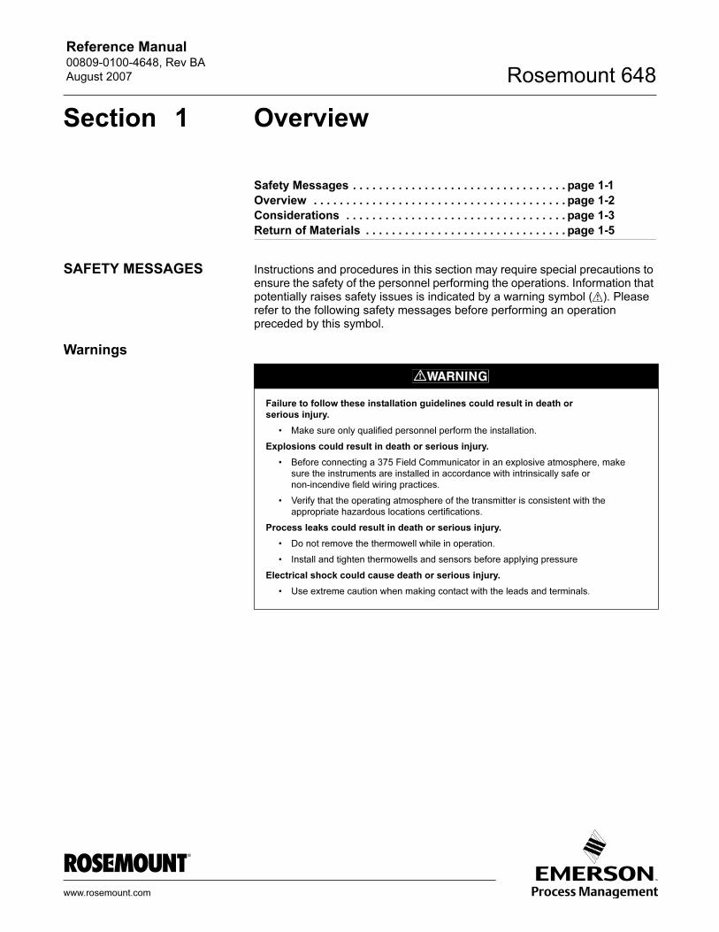
SAFETY MESSAGES Instructions and procedures in this section may require special precautions to ensure the safety of the personnel performing the operations. Information that potentially raises safety issues is indicated by a warning symbol ( ). Please refer to the following safety messages before performing an operation preceded by this symbol.
Warnings
Failure to follow these installation guidelines could result in death or
serious injury.
• Make sure only qualified personnel perform the installation.
Explosions could result in death or serious injury.
• Before connecting a 375 Field Communicator in an explosive atmosphere, make
sure the instruments are installed in accordance with intrinsically safe or
non-incendive field wiring practices.
• Verify that the operating atmosphere of the transmitter is consistent with the
appropriate hazardous locations certifications.
Process leaks could result in death or serious injury.
• Do not remove the thermowell while in operation.
• Install and tighten thermowells and sensors before applying pressure
Electrical shock could cause death or serious injury.
• Use extreme caution when making contact with the leads and terminals.
Reference Manual00809-0100-4648, Rev BA
August 2007Rosemount 648
1-2
OVERVIEW
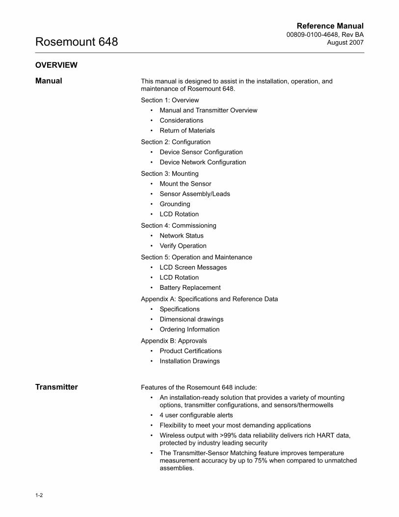
Manual This manual is designed to assist in the installation, operation, and maintenance of Rosemount 648.
Section 1: Overview
• Manual and Transmitter Overview
• Considerations
• Return of Materials
Section 2: Configuration
• Device Sensor Configuration
• Device Network Configuration
Section 3: Mounting
• Mount the Sensor
• Sensor Assembly/Leads
• Grounding
• LCD Rotation
Section 4: Commissioning
• Network Status
• Verify Operation
Section 5: Operation and Maintenance
• LCD Screen Messages
• LCD Rotation
• Battery Replacement
Appendix A: Specifications and Reference Data
• Specifications
• Dimensional drawings
• Ordering Information
Appendix B: Approvals
• Product Certifications
• Installation Drawings
Transmitter Features of the Rosemount 648 include:
• An installation-ready solution that provides a variety of mounting options, transmitter configurations, and sensors/thermowells
• 4 user configurable alerts
• Flexibility to meet your most demanding applications
• Wireless output with >99% data reliability delivers rich HART data, protected by industry leading security
• The Transmitter-Sensor Matching feature improves temperature measurement accuracy by up to 75% when compared to unmatched assemblies.
Reference Manual 00809-0100-4648, Rev BA
August 2007
1-3
Rosemount 648
• The integral LCD conveniently displays the primary sensor input and diagnostics of the transmitter
• Simple and easy installation practices already used today for robust installations
Refer to the following literatures for a full range of compatible connection heads, sensors, and thermowells provided by Emerson Process Management.
• English Temperature Sensors and Assemblies Product Data Sheet, Volume 1 (document number 00813-0100-2654)
• Temperature Sensors and Accessories (Metric Sensors) Product Data Sheet, Volume 2 (document number 00813-0200-2654)
CONSIDERATIONS
General Electrical temperature sensors such as RTDs and thermocouples produce low-level signals proportional to their sensed temperature. With simple HART configuration, the Rosemount 648 converts the low-level sensor signal to a wireless-enabled signal.
Commissioning The transmitter can be commissioned before or after installation. It may be useful to commission it on the bench, before installation, to ensure proper operation and to become familiar with its functionality. When applicable, make sure the instruments are installed in accordance with intrinsically safe or non-incendive field wiring practices. The device will be powered whenever the battery is installed. To avoid depleting the battery, make sure it is removed when the device is not in use.
Mechanical Location
When choosing an installation location and position, take into account the need for access to the transmitter. For best performance, the antenna should be vertical with some space between objects in a parallel metal plane such as a pipe or metal framework, as the pipes or framework may adversely affect the performance of the antenna.
Electrical Battery
The Rosemount 648 Wireless Temperature transmitter is battery powered. The battery pack with the wireless unit contains 2 “C” size primary lithium/thionyl chloride batteries. Each battery contains approximately 2.5 grams of lithium, for a total of 5 grams in each pack. Under normal conditions, the battery materials are self-contained and are not reactive as long as the batteries and the battery pack are maintained. Care should be taken to prevent thermal, electrical or mechanical damage. Contacts should be protected to prevent premature discharge.
Use caution when handling the battery pack. The battery pack may be damaged if dropped from heights in excess of 20 feet.
Sensor
Make sensor connections through the cable entry in the side of the connection head. Be sure to provide adequate clearance for cover removal.
Reference Manual00809-0100-4648, Rev BA
August 2007Rosemount 648
1-4
Environmental Verify that the operating atmosphere of the transmitter is consistent with the appropriate hazardous locations certifications.
Temperature Effects
The transmitter will operate within specifications for ambient temperatures between –40 and 185 °F (–40 and 85 °C). Heat from the process is transferred from the thermowell to the transmitter housing. If the expected process temperature is near or beyond specification limits, consider the use of additional thermowell and extension, or remote mounting the transmitter to thermally isolate it from the process.
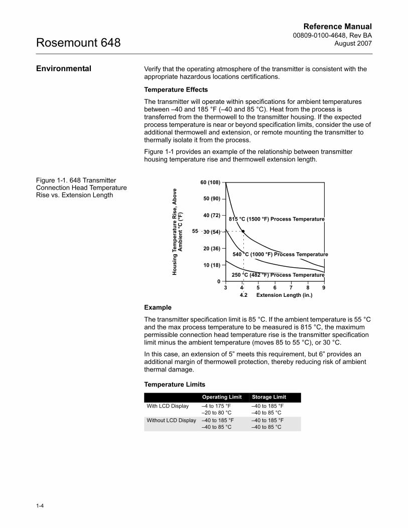
Figure 1-1 provides an example of the relationship between transmitter housing temperature rise and thermowell extension length.
Figure 1-1. 648 Transmitter Connection Head Temperature Rise vs. Extension Length
Example
The transmitter specification limit is 85 °C. If the ambient temperature is 55 °C and the max process temperature to be measured is 815 °C, the maximum permissible connection head temperature rise is the transmitter specification limit minus the ambient temperature (moves 85 to 55 °C), or 30 °C.
In this case, an extension of 5” meets this requirement, but 6” provides an additional margin of thermowell protection, thereby reducing risk of ambient thermal damage.
Temperature Limits
Operating Limit Storage Limit
With LCD Display –4 to 175 °F
–20 to 80 °C
–40 to 185 °F
–40 to 85 °C
Without LCD Display –40 to 185 °F
–40 to 85 °C
–40 to 185 °F
–40 to 85 °C
Ho
us
ing
Te
mp
era
ture
Ris
e, A
bo
ve
A
mb
ien
t °C
(°F
)
3 4 5 6 7 8 90
60 (108)
50 (90)
40 (72)
30 (54)
20 (36)
10 (18)
4.2
55
Extension Length (in.)
815 °C (1500 °F) Process Temperature
540 °C (1000 °F) Process Temperature
250 °C (482 °F) Process Temperature
Reference Manual 00809-0100-4648, Rev BA
August 2007
1-5
Rosemount 648
RETURN OF MATERIALS To expedite the return process in North America, call the Emerson Process Management National Response Center toll-free at 800-654-7768. This center, available 24 hours a day, will assist you with any needed information or materials.
The center will ask for the following information:
• Product model
• Serial numbers
• The last process material to which the product was exposed
The center will provide
• A Return Material Authorization (RMA) number
• Instructions and procedures that are necessary to return goods that were exposed to hazardous substances
For other locations outside North America, please contact an Emerson Process Management sales representative for further instructions.
NOTEIf the device has been exposed to a hazardous substance, a Material Safety Data Sheet (MSDS) must be included with the returned materials. An MSDS is required by law to be available to people exposed to specific hazardous substances.
SHIPPING CONSIDERATIONS FOR WIRELESS PRODUCTS (LITHIUM BATTERIES):The unit was shipped to you without the battery installed. Please remove the battery pack prior to shipping the unit.
Primary lithium batteries (charged or discharged) are regulated in transportation by the U.S. Department of Transportation, and are also covered by IATA (International Air Transport Association), ICAO (International Civil Aviation Organization), and ARD (European Ground Transportation of Dangerous Goods). It is the responsibility of the shipper to ensure compliance with these or any other local requirements. Please consult current regulations and requirements before shipping.

Reference Manual00809-0100-4648, Rev BA
August 2007Rosemount 648
1-6
Reference Manual 00809-0100-4648, Rev BA
August 2007 Rosemount 648
www.rosemount.com
Section 2 Configuration
Safety Messages . . . . . . . . . . . . . . . . . . . . . . . . . . . . . . . . . page 2-1
Device Sensor Configuration . . . . . . . . . . . . . . . . . . . . . . page 2-6
Device Network Configuration . . . . . . . . . . . . . . . . . . . . . page 2-6
Fast Key Sequence . . . . . . . . . . . . . . . . . . . . . . . . . . . . . . . page 2-9
Remove Battery . . . . . . . . . . . . . . . . . . . . . . . . . . . . . . . . . page 2-13
SAFETY MESSAGES Instructions and procedures in this section may require special precautions to ensure the safety of the personnel performing the operations. Information that potentially raises safety issues is indicated by a warning symbol ( ). Please refer to the following safety messages before performing an operation preceded by this symbol.
Warnings
Failure to follow these installation guidelines could result in death or
serious injury.
• Make sure only qualified personnel perform the installation.
Explosions could result in death or serious injury.
• Before connecting a 375 Field Communicator in an explosive atmosphere, make
sure the instruments are installed in accordance with intrinsically safe or
non-incendive field wiring practices.
• Verify that the operating atmosphere of the transmitter is consistent with the
appropriate hazardous locations certifications.
Process leaks could result in death or serious injury.
• Do not remove the thermowell while in operation.
• Install and tighten thermowells and sensors before applying pressure
Electrical shock could cause death or serious injury.
• Use extreme caution when making contact with the leads and terminals.
This device complies with Part 15 of the FCC Rules. Operation is subject to the following
conditions: This device may not cause harmful interference, this device must accept any
interference received, including interference that may cause undesired operation.
This device must be installed to ensure a minimum antenna separation distance of 20 cm
from all persons.
Reference Manual00809-0100-4648, Rev BA
August 2007Rosemount 648
2-2
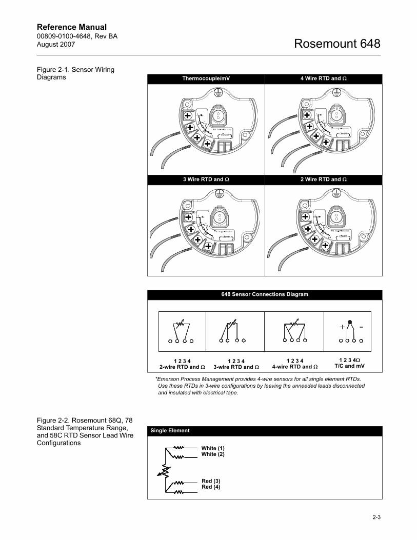
Sensor Connections The 648 is compatible with a number of RTD and thermocouple sensor types. Figure 2-1 shows the correct input connections to the sensor terminals on the transmitter. To ensure a proper sensor connection, anchor the sensor lead wires into the appropriate compression terminals and tighten the screws.
Thermocouple or Millivolts Inputs
The thermocouple can be connected directly to the transmitter. Use appropriate thermocouple extension wire if mounting the transmitter remotely from the sensor. Make millivolt inputs connections with copper wire. Use shielding for long runs of wire.
RTD or Ohm Inputs
The transmitters will accept a variety of RTD configurations, including 2-wire, 3-wire, 4-wire. If the transmitter is mounted remotely from a 3-wire or 4-wire RTD, it will operate within specifications, without recalibration, for lead wire resistances of up to 5 ohms per lead (equivalent to 500 feet of 20 AWG wire). In this case, the leads between the RTD and transmitter should be shielded. If using only two leads, both RTD leads are in series with the sensor element, so significant errors can occur if the lead lengths exceed three feet of 20 AWG wire (approximately 0.05 °C/ft.). For longer runs, attach a third or fourth lead as described above.
Sensor Lead Wire Resistance Effect—RTD Input
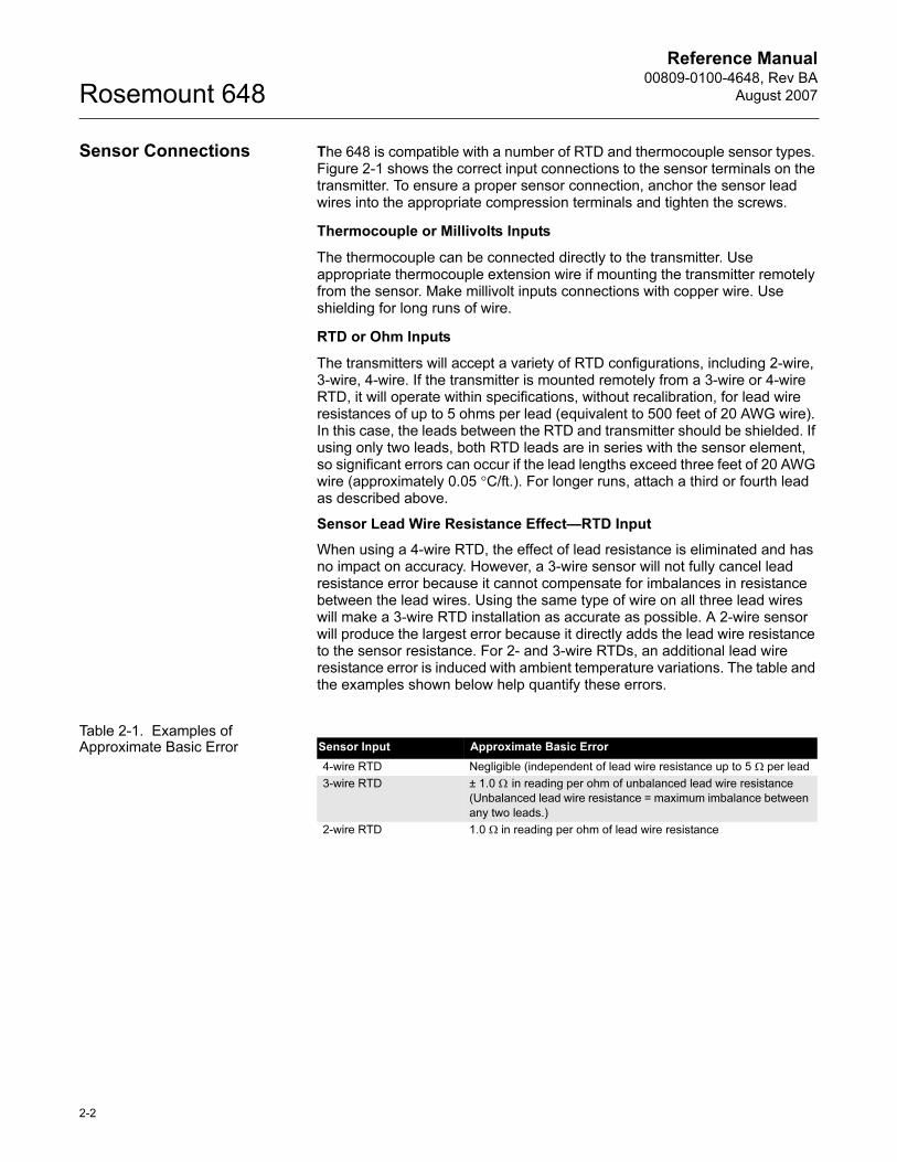
When using a 4-wire RTD, the effect of lead resistance is eliminated and has no impact on accuracy. However, a 3-wire sensor will not fully cancel lead resistance error because it cannot compensate for imbalances in resistance between the lead wires. Using the same type of wire on all three lead wires will make a 3-wire RTD installation as accurate as possible. A 2-wire sensor will produce the largest error because it directly adds the lead wire resistance to the sensor resistance. For 2- and 3-wire RTDs, an additional lead wire resistance error is induced with ambient temperature variations. The table and the examples shown below help quantify these errors.
Table 2-1. Examples of Approximate Basic Error Sensor Input Approximate Basic Error
4-wire RTD Negligible (independent of lead wire resistance up to 5 Ω per lead
3-wire RTD ± 1.0 Ω in reading per ohm of unbalanced lead wire resistance
(Unbalanced lead wire resistance = maximum imbalance between
any two leads.)
2-wire RTD 1.0 Ω in reading per ohm of lead wire resistance
Reference Manual 00809-0100-4648, Rev BA
August 2007
2-3
Rosemount 648
Figure 2-1. Sensor Wiring Diagrams
*Emerson Process Management provides 4-wire sensors for all single element RTDs.
Use these RTDs in 3-wire configurations by leaving the unneeded leads disconnected
and insulated with electrical tape.
Figure 2-2. Rosemount 68Q, 78 Standard Temperature Range, and 58C RTD Sensor Lead Wire Configurations
Thermocouple/mV 4 Wire RTD and Ω
3 Wire RTD and Ω 2 Wire RTD and Ω
648 Sensor Connections Diagram
Single Element
White (1)White (2)
Red (3)Red (4)
1 2 3 4ΩT/C and mV
1 2 3 44-wire RTD and Ω
1 2 3 43-wire RTD and Ω
1 2 3 42-wire RTD and Ω
Reference Manual00809-0100-4648, Rev BA
August 2007Rosemount 648
2-4
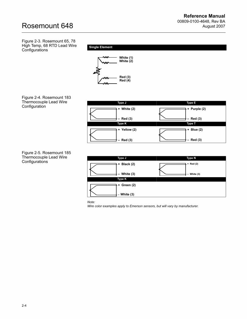
Figure 2-3. Rosemount 65, 78 High Temp, 68 RTD Lead Wire Configurations
Figure 2-4. Rosemount 183 Thermocouple Lead Wire Configuration
Figure 2-5. Rosemount 185 Thermocouple Lead Wire Configurations
Note:
Wire color examples apply to Emerson sensors, but will vary by manufacturer.
Single Element
White (1)White (2)
Red (3)Red (4)
Type J Type E
Type K Type T
+ White (2)
– Red (3)
+ Purple (2)
– Red (3)
+ Yellow (2)
– Red (3)
+ Blue (2)
– Red (3)
Type J Type N
Type K
+ Black (2)
– White (3)
+ Red (2)
– White (3)
+ Green (2)
– White (3)
Reference Manual 00809-0100-4648, Rev BA
August 2007
2-5
Rosemount 648
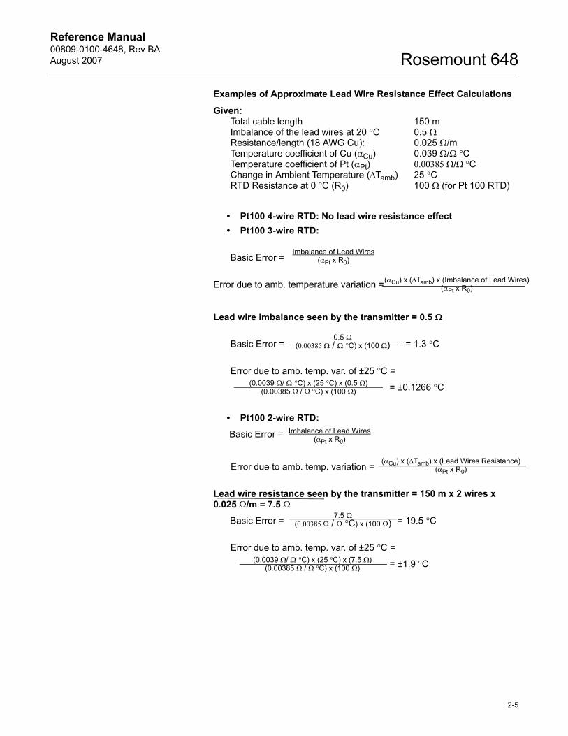
Examples of Approximate Lead Wire Resistance Effect Calculations
Given:Total cable length 150 mImbalance of the lead wires at 20 °C 0.5 ΩResistance/length (18 AWG Cu): 0.025 Ω/mTemperature coefficient of Cu (αCu) 0.039 Ω/Ω °CTemperature coefficient of Pt (αPt) 0.00385 Ω/Ω °CChange in Ambient Temperature (ΔTamb) 25 °CRTD Resistance at 0 °C (R0) 100 Ω (for Pt 100 RTD)
• Pt100 4-wire RTD: No lead wire resistance effect
• Pt100 3-wire RTD:
Basic Error =
Error due to amb. temperature variation =
Lead wire imbalance seen by the transmitter = 0.5 Ω
Basic Error = = 1.3 °C
Error due to amb. temp. var. of ±25 °C =
= ±0.1266 °C
• Pt100 2-wire RTD:
Basic Error =
Error due to amb. temp. variation =
Lead wire resistance seen by the transmitter = 150 m x 2 wires x 0.025 Ω/m = 7.5 Ω
Basic Error = = 19.5 °C
Error due to amb. temp. var. of ±25 °C =
= ±1.9 °C
0.5 Ω(0.00385 Ω / Ω °C) x (100 Ω)
(0.0039 Ω/ Ω °C) x (25 °C) x (0.5 Ω)(0.00385 Ω / Ω °C) x (100 Ω)
Imbalance of Lead Wires(αPt x R0)
(αCu) x (ΔTamb) x (Imbalance of Lead Wires)(αPt x R0)
7.5 Ω(0.00385 Ω / Ω °C) x (100 Ω)
(0.0039 Ω/ Ω °C) x (25 °C) x (7.5 Ω)(0.00385 Ω / Ω °C) x (100 Ω)
Imbalance of Lead Wires(αPt x R0)
(αCu) x (ΔTamb) x (Lead Wires Resistance)(αPt x R0)
Reference Manual00809-0100-4648, Rev BA
August 2007Rosemount 648
2-6
Sensor Leads
If the sensor is installed in a high-voltage environment and a fault condition or installation error occurs, the sensor leads and transmitter terminals could carry lethal voltages. Use extreme caution when making contact with the leads and terminals.
Use the following steps to wire the sensor and supply power to the transmitter:
1. Remove the transmitter enclosure cover (if applicable).
2. Attach the sensor leads according to the wiring diagrams.
3. Connect the battery.
4. Verify the connection by observing the LCD.
5. Reattach and tighten the cover (if applicable).
DEVICE SENSOR CONFIGURATION
Every temperature sensor has unique characteristics. In order to ensure the most accurate measurement, the Rosemount 648 should be configured to match the specific sensor that it will be connected to.
Begin by removing the battery-side housing cover. This will expose the terminal block and HART communication terminals. Connect the battery to supply power for configuration.
The Rosemount 648 will receive any HART communications from a handheld Field Communicator, or AMS. When using a Field Communicator, any configuration changes must be sent to the transmitter by using the Send key (F2). AMS configuration changes are implemented when the Apply button is clicked.
AMS Wireless and Direct Connections
AMS is capable of connecting to devices either directly, using a HART modem, or wirelessly via the 1420. When configuring on the bench using a HART modem, double click the device icon (or right click and select Configure/Setup), then choose the Configure/Setup tab. Configure the device settings using the Direct Connection menu. When configuring wirelessly via the 1420, double click the device icon (or right click and select Configure/Setup), then choose the Configure/Setup tab. Configure the device settings using the Wireless Connection menu.
To check or change sensor configuration using a 375 Field Communicator, enter the following Fast Key Sequence: 1, 3, 2, 1.
When the device configuration is 2 wire or 3 wire, terminal 4 of the device must be left disconnected. If connected, a configuration error may be indicated, which then prevents the device from providing process temperature measurements.
DEVICE NETWORK CONFIGURATION
In order to communicate with the 1420 Wireless Gateway, and ultimately the Information System, the transmitter must be configured to communicate with the wireless network. This step is the wireless equivalent of connecting wires from a transmitter to the information system.
Reference Manual 00809-0100-4648, Rev BA
August 2007
2-7
Rosemount 648
Using a Field Communicator or AMS, enter the Network ID and Join Key so that they match the Network ID and Join Key of the gateway and other devices in the network. If the Network ID and Join Key are not identical, the transmitter will not communicate with the network. The Network ID and Join Key may be obtained from the 1420 Wireless Gateway on the Setup>Network>Settings page on the web server.
The final device network configuration piece is the Update Rate. This by default is 5 minutes. This may be changed at commissioning, or at any time via AMS or the 1420 Wireless Gateway’s web server. The Update Rate should be between 15 seconds and 60 minutes. For networks of up to 100 wireless devices, fastest Update Rate is 60 seconds. For networks of 50 or fewer devices, the fastest Update Rate is 15 seconds
When device configuration is completed, remove the battery and replace the battery cover. Tighten the cover to the proper tension for safety approvals.
To access the Network Settings using a 375 Field Communicator, enter the following Fast Key Sequence: 1, 3, 3.
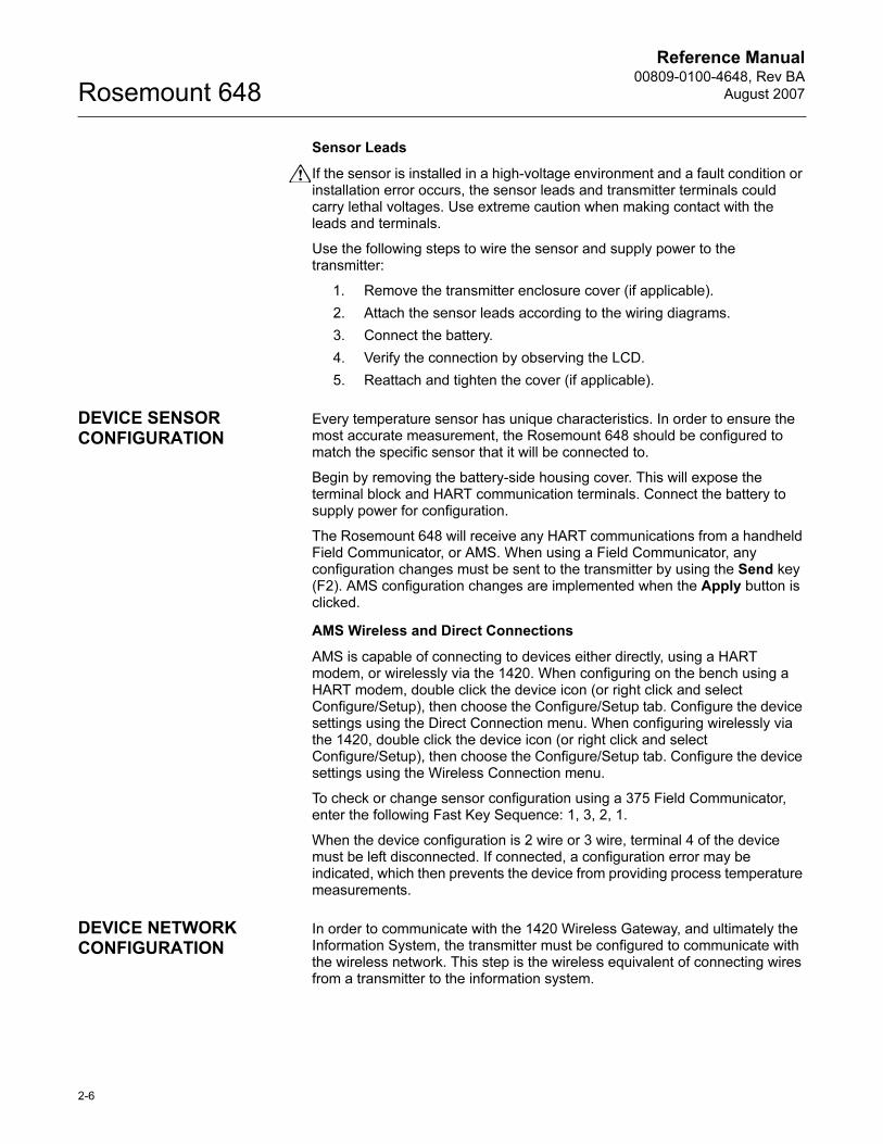
Figure 2-6. 648 Terminal Block
Connect the HART communication leads to the COMM terminals on the terminal block.
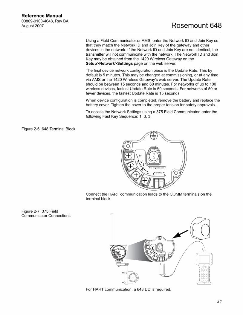
Figure 2-7. 375 Field Communicator Connections
For HART communication, a 648 DD is required.
1
2
3
4
COMM
P/N 00753-9200-0020
1
2
3
4
Reference Manual00809-0100-4648, Rev BA
August 2007Rosemount 648
2-8
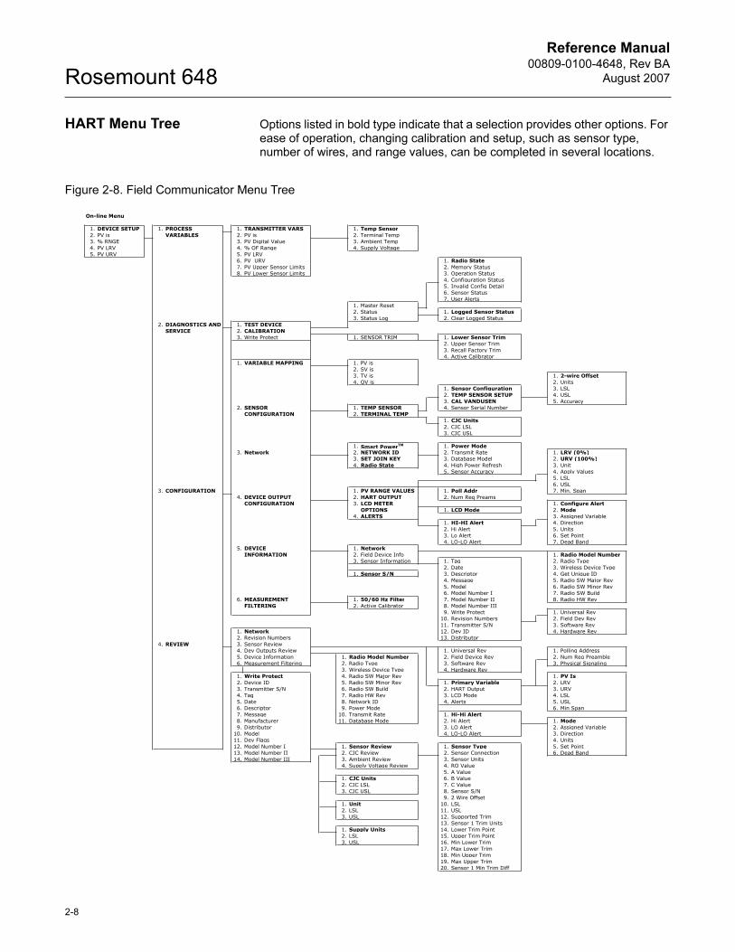
HART Menu Tree Options listed in bold type indicate that a selection provides other options. For ease of operation, changing calibration and setup, such as sensor type, number of wires, and range values, can be completed in several locations.
Figure 2-8. Field Communicator Menu Tree
On-line Menu
1. DEVICE SETUP 1. PROCESS 1. TRANSMITTER VARS 1. Temp Sensor2. PV is VARIABLES 2. PV is 2. Terminal Temp3. % RNGE 3. PV Digital Value 3. Ambient Temp4. PV LRV 4. % OF Range 4. Supply Voltage5. PV URV 5. PV LRV
6. PV URV 1. Radio State7. PV Upper Sensor Limits 2. Memory Status8. PV Lower Sensor Limits 3. Operation Status
4. Configuration Status5. Invalid Config Detail6. Sensor Status7. User Alerts
1. Master Reset2. Status 1. Logged Sensor Status3. Status Log 2. Clear Logged Status
2. DIAGNOSTICS AND 1. TEST DEVICESERVICE 2. CALIBRATION
3. Write Protect 1. SENSOR TRIM 1. Lower Sensor Trim2. Upper Sensor Trim3. Recall Factory Trim4. Active Calibrator
1. VARIABLE MAPPING 1. PV is2. SV is3. TV is 1. 2-wire Offset4. QV is 2. Units
1. Sensor Configuration 3. LSL2. TEMP SENSOR SETUP 4. USL3. CAL VANDUSEN 5. Accuracy
2. SENSOR 1. TEMP SENSOR 4. Sensor Serial NumberCONFIGURATION 2. TERMINAL TEMP
1. CJC Units2. CJC LSL3. CJC USL
1. Smart PowerTM 1. Power Mode3. Network 2. NETWORK ID 2. Transmit Rate 1. LRV (0%)
3. SET JOIN KEY 3. Database Model 2. URV (100%)4. Radio State 4. High Power Refresh 3. Unit
5. Sensor Accuracy 4. Apply Values5. LSL6. USL
3. CONFIGURATION 1. PV RANGE VALUES 1. Poll Addr 7. Min. Span4. DEVICE OUTPUT 2. HART OUTPUT 2. Num Req Preams
CONFIGURATION 3. LCD METER 1. Configure AlertOPTIONS 1. LCD Mode 2. Mode
4. ALERTS 3. Assigned Variable1. HI-HI Alert 4. Direction2. Hi Alert 5. Units3. Lo Alert 6. Set Point4. LO-LO Alert 7. Dead Band
5. DEVICE 1. NetworkINFORMATION 2. Field Device Info 1. Radio Model Number
3. Sensor Information 1. Tag 2. Radio Type2. Date 3. Wireless Device Type
1. Sensor S/N 3. Descriptor 4. Get Unique ID4. Message 5. Radio SW Major Rev5. Model 6. Radio SW Minor Rev6. Model Number I 7. Radio SW Build
6. MEASUREMENT 1. 50/60 Hz Filter 7. Model Number II 8. Radio HW RevFILTERING 2. Active Calibrator 8. Model Number III
9. Write Protect 1. Universal Rev10. Revision Numbers 2. Field Dev Rev11. Transmitter S/N 3. Software Rev
1. Network 12. Dev ID 4. Hardware Rev2. Revision Numbers 13. Distributor
4. REVIEW 3. Sensor Review4. Dev Outputs Review 1. Universal Rev 1. Polling Address5. Device Information 1. Radio Model Number 2. Field Device Rev 2. Num Req Preamble6. Measurement Filtering 2. Radio Type 3. Software Rev 3. Physical Signaling
3. Wireless Device Type 4. Hardware Rev1. Write Protect 4. Radio SW Major Rev 1. PV Is2. Device ID 5. Radio SW Minor Rev 1. Primary Variable 2. LRV3. Transmitter S/N 6. Radio SW Build 2. HART Output 3. URV4. Tag 7. Radio HW Rev 3. LCD Mode 4. LSL5. Date 8. Network ID 4. Alerts 5. USL6. Descriptor 9. Power Mode 6. Min Span7. Message 10. Transmit Rate 1. Hi-Hi Alert8. Manufacturer 11. Database Mode 2. Hi Alert 1. Mode9. Distributor 3. LO Alert 2. Assigned Variable
10. Model 4. LO-LO Alert 3. Direction11. Dev Flags 4. Units12. Model Number I 1. Sensor Review 1. Sensor Type 5. Set Point13. Model Number II 2. CJC Review 2. Sensor Connection 6. Dead Band14. Model Number III 3. Ambient Review 3. Sensor Units
4. Supply Voltage Review 4. RO Value5. A Value
1. CJC Units 6. B Value2. CJC LSL 7. C Value3. CJC USL 8. Sensor S/N
9. 2 Wire Offset1. Unit 10. LSL2. LSL 11. USL3. USL 12. Supported Trim
13. Sensor 1 Trim Units1. Supply Units 14. Lower Trim Point2. LSL 15. Upper Trim Point3. USL 16. Min Lower Trim
17. Max Lower Trim18. Min Upper Trim19. Max Upper Trim20. Sensor 1 Min Trim Diff
Reference Manual 00809-0100-4648, Rev BA
August 2007
2-9
Rosemount 648
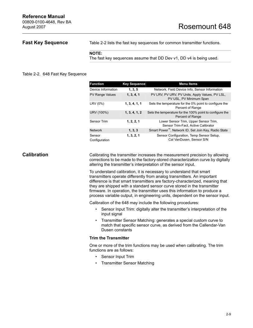
Fast Key Sequence Table 2-2 lists the fast key sequences for common transmitter functions.
NOTE:The fast key sequences assume that DD Dev v1, DD v4 is being used.
Table 2-2. 648 Fast Key Sequence
Calibration Calibrating the transmitter increases the measurement precision by allowing corrections to be made to the factory-stored characterization curve by digitally altering the transmitter’s interpretation of the sensor input.
To understand calibration, it is necessary to understand that smart transmitters operate differently from analog transmitters. An important difference is that smart transmitters are factory-characterized, meaning that they are shipped with a standard sensor curve stored in the transmitter firmware. In operation, the transmitter uses this information to produce a process variable output, in engineering units, dependent on the sensor input.
Calibration of the 648 may include the following procedures:
• Sensor Input Trim: digitally alter the transmitter’s interpretation of the input signal
• Transmitter Sensor Matching: generates a special custom curve to match that specific sensor curve, as derived from the Callendar-Van Dusen constants
Trim the Transmitter
One or more of the trim functions may be used when calibrating. The trim functions are as follows:
• Sensor Input Trim
• Transmitter Sensor Matching
Function Key Sequence Menu Items
Device Information 1, 3, 5 Network, Field Device Info, Sensor Information
PV Range Values 1, 3, 4, 1 PV LRV, PV URV, PV Units, Apply Values, PV LSL,
PV USL, PV Minimum Span
LRV (0%) 1, 3, 4, 1, 1 Sets the temperature for the 0% point to configure the
Percent of Range
URV (100%) 1, 3, 4, 1, 2 Sets the temperature for the 100% point to configure the
Percent of Range
Sensor Trim 1, 2, 2, 1 Lower Sensor Trim, Upper Sensor Trim,
Sensor Trim-Fact, Active Calibrator
Network 1, 3, 3 Smart Power™, Network ID, Set Join Key, Radio State
Sensor
Configuration
1, 3, 2, 1 Sensor Configuration, Temp Sensor Setup,
Cal VanDusen, Sensor S/N
Reference Manual00809-0100-4648, Rev BA
August 2007Rosemount 648
2-10
Sensor Input Trim
Perform a sensor trim if the transmitters digital value for the primary variable does not match the plant’s standard calibration equipment. The sensor trim function calibrates the sensor to the transmitter in temperature units or raw units. Unless your site-standard input source is NIST-traceable, the trim functions will not maintain the NIST-traceability of the system.
The Sensor Input Trim command allows the transmitter’s interpretation of the input signal to be digitally altered. The sensor reference command trims, in engineering (°F, °C,°R, K) or raw (Ω, mV) units, the combined sensor and transmitter system to a site standard using a known temperature source. Sensor trimming is suitable for validation procedures or for applications that require calibrating the sensor and transmitter together.
Use the following procedure to perform a sensor trim with a 648:
1. Connect the calibration device or sensor to the transmitter. Refer to Figure 2-1 on page 2-3 or on the device terminal block for sensor wiring diagrams.
2. Connect the communicator to the transmitter.
3. From the Home screen, select 1 Device Setup, 2 Diagnostics and Service, 2 Calibration, 1 Sensor Trim to prepare to trim the sensor.
4. Select 1 Lower Sensor Trim or 2 Upper Sensor Trim. (Note: It is recommended to perform lower offset trims first, before performing upper slope trims).
5. Answer the question about using an active calibrator or not.
6. Adjust the calibration device to the desired trim value (must be within the selected sensor limits). If a combined sensor and transmitter system are being trimmed, expose the sensor to a known temperature and allow the temperature reading to stabilize. Use a bath, furnace or isothermal block, measured with a site-standard thermometer, as the known temperature source.
7. Select OK once the temperature stabilizes. The communicator displays the output value the transmitter associates with the input value provided by the calibration device.
8. Select the appropriate sensor trim units at the prompt.
9. Enter the trim point.
AMS
For AMS, configure the sensor as indicated above.
Right click on the device and select “Methods>Calibrate>Sensor Calibration” from the menu. Select “Lower Input Trim” or “Upper Limit Trim.”
The wizard will continue through the process.
The transmitter may be restored to the factory default by selecting: “Methods>Calibrate>Sensor Calibration>Revert to Factory Trim.”
The wizard will recall the factory trim for a given sensor.
Apply changes
Fast Key Sequence 1, 2, 2, 1
Reference Manual 00809-0100-4648, Rev BA
August 2007
2-11
Rosemount 648
Transmitter-Sensor Matching
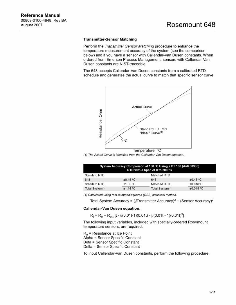
Perform the Transmitter Sensor Matching procedure to enhance the temperature measurement accuracy of the system (see the comparison below) and if you have a sensor with Callendar-Van Dusen constants. When ordered from Emerson Process Management, sensors with Callendar-Van Dusen constants are NIST-traceable.
The 648 accepts Callendar-Van Dusen constants from a calibrated RTD schedule and generates the actual curve to match that specific sensor curve.
(1) The Actual Curve is identified from the Callendar-Van Dusen equation.
(1) Calculated using root-summed-squared (RSS) statistical method.
Total System Accuracy = ( Transmitter Accuracy)2 + (Sensor Accuracy)2
Callendar-Van Dusen equation:
Rt = Ro + Roα [t - δ(0.01t-1)(0.01t) - β(0.01t - 1)(0.01t)3]
The following input variables, included with specially-ordered Rosemount temperature sensors, are required:
Ro = Resistance at Ice PointAlpha = Sensor Specific ConstantBeta = Sensor Specific ConstantDelta = Sensor Specific Constant
To input Callendar-Van Dusen constants, perform the following procedure:
System Accuracy Comparison at 150 °C Using a PT 100 (A=0.00385)
RTD with a Span of 0 to 200 °C
Standard RTD Matched RTD
648 ±0.45 °C 648 ±0.45 °C
Standard RTD ±1.05 °C Matched RTD ±0.018°C
Total System(1) ±1.14 °C Total System(1) ±0.048 °C
Resis
tance
, O
hm
Temperature, °C
Standard IEC 751
"Ideal" Curve(1)
Actual Curve
0 °C
Reference Manual00809-0100-4648, Rev BA
August 2007Rosemount 648
2-12
1. From the HOME screen, select 1 Device Setup, 3 Configuration, 2 Sensor Configuration, 1 Temp Sensor, 1 Sensor Configuration.
2. Select Cal VanDusen at the ENTER SENSOR TYPE prompt.
3. Select the appropriate number of wires at the ENTER SENSOR CONNECTION prompt.
4. Enter the Ro, Alpha, Delta, and Beta values from the stainless steel tag attached to the special-order sensor when prompted.
To disable the transmitter-sensor matching feature from the HOME screen select 1 Device Setup, 3 Configuration, 2 Sensor Configuration, 1 Temp Sensor, 1 Sensor Configuration. Choose the appropriate sensor type from the ENTER SENSOR TYPE prompt.
NOTEWhen the transmitter-sensor matching is disabled, the transmitter reverts to factory trim. Make certain the transmitter engineering units default correctly before placing the transmitter into service.
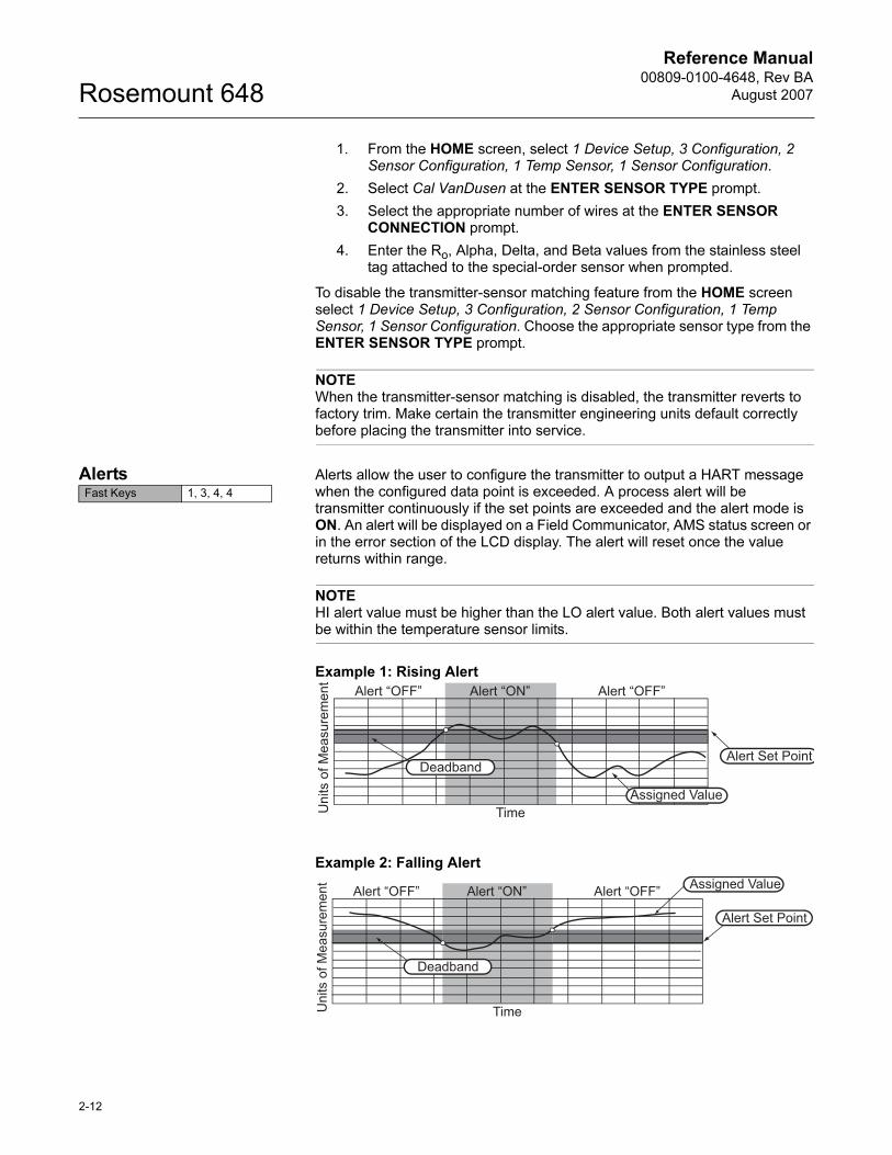
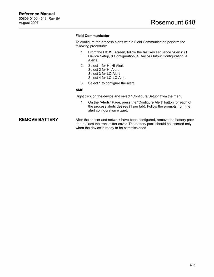
Alerts Alerts allow the user to configure the transmitter to output a HART message when the configured data point is exceeded. A process alert will be transmitter continuously if the set points are exceeded and the alert mode is ON. An alert will be displayed on a Field Communicator, AMS status screen or in the error section of the LCD display. The alert will reset once the value returns within range.
NOTEHI alert value must be higher than the LO alert value. Both alert values must be within the temperature sensor limits.
Example 1: Rising Alert
Example 2: Falling Alert
Fast Keys 1, 3, 4, 4
Deadband
Assigned Value
Alert Set Point
Alert “OFF” Alert “ON” Alert “OFF”
Units o
f M
easure
ment
Time
Deadband
Assigned Value
Alert Set Point
Alert “OFF” Alert “ON” Alert “OFF”
Units o
f M
easure
ment
Time
Reference Manual 00809-0100-4648, Rev BA
August 2007
2-13
Rosemount 648
Field Communicator
To configure the process alerts with a Field Communicator, perform the following procedure:
1. From the HOME screen, follow the fast key sequence “Alerts” (1 Device Setup, 3 Configuration, 4 Device Output Configuration, 4 Alerts).
2. Select 1 for HI-HI Alert.Select 2 for HI AlertSelect 3 for LO AlertSelect 4 for LO-LO Alert
3. Select 1 to configure the alert.
AMS
Right click on the device and select “Configure/Setup” from the menu.
1. On the “Alerts” Page, press the “Configure Alert” button for each of the process alerts desires (1 per tab). Follow the prompts from the alert configuration wizard.
REMOVE BATTERY After the sensor and network have been configured, remove the battery pack and replace the transmitter cover. The battery pack should be inserted only when the device is ready to be commissioned.

Reference Manual00809-0100-4648, Rev BA
August 2007Rosemount 648
2-14
Reference Manual 00809-0100-4648, Rev BA
August 2007 Rosemount 648
www.rosemount.com
Section 3 Mounting
Safety Messages . . . . . . . . . . . . . . . . . . . . . . . . . . . . . . . . . page 3-1
Mounting . . . . . . . . . . . . . . . . . . . . . . . . . . . . . . . . . . . . . . . page 3-2
Direct Mount . . . . . . . . . . . . . . . . . . . . . . . . . . . . . . . . . . . . page 3-2
Remote Mount . . . . . . . . . . . . . . . . . . . . . . . . . . . . . . . . . . . page 3-4
LCD Display . . . . . . . . . . . . . . . . . . . . . . . . . . . . . . . . . . . . . page 3-5
Ground the Transmitter . . . . . . . . . . . . . . . . . . . . . . . . . . . page 3-5
SAFETY MESSAGES Instructions and procedures in this section may require special precautions to ensure the safety of the personnel performing the operations. Information that potentially raises safety issues is indicated by a warning symbol ( ). Please refer to the following safety messages before performing an operation preceded by this symbol.
Warnings
Failure to follow these installation guidelines could result in death or
serious injury.
• Make sure only qualified personnel perform the installation.
Explosions could result in death or serious injury.
• Before connecting a 375 Field Communicator in an explosive atmosphere, make
sure the instruments are installed in accordance with intrinsically safe or
non-incendive field wiring practices.
• Verify that the operating atmosphere of the transmitter is consistent with the
appropriate hazardous locations certifications.
Process leaks could result in death or serious injury.
• Do not remove the thermowell while in operation.
• Install and tighten thermowells and sensors before applying pressure
Electrical shock could cause death or serious injury.
• Use extreme caution when making contact with the leads and terminals.
Reference Manual00809-0100-4648, Rev BA
August 2007Rosemount 648
3-2
MOUNTING The Rosemount 648 can be installed in one of two configurations: Direct Mount, where the sensor is connected directly to the 648 housing’s conduit entry, or Remote Mount, where the sensor is mounted separate from the 648 housing, then connected to the 648 via conduit. Choose the installation sequence that corresponds to the mounting configuration.
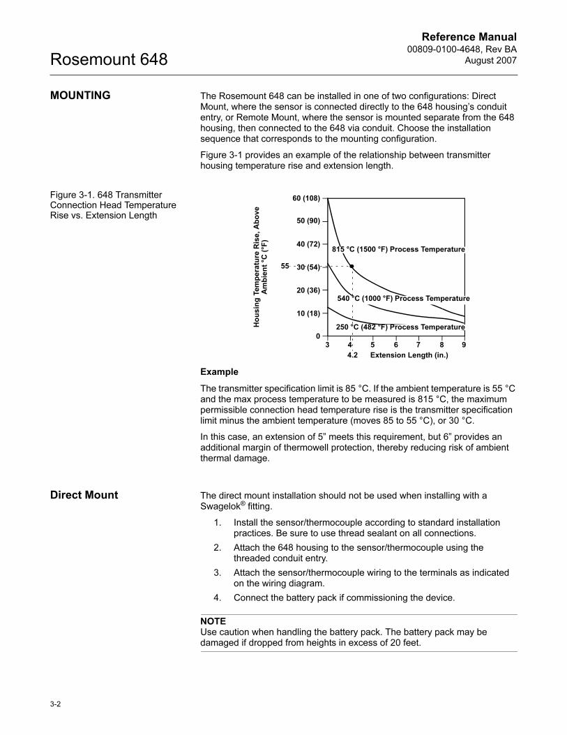
Figure 3-1 provides an example of the relationship between transmitter housing temperature rise and extension length.
Figure 3-1. 648 Transmitter Connection Head Temperature Rise vs. Extension Length
Example
The transmitter specification limit is 85 °C. If the ambient temperature is 55 °C and the max process temperature to be measured is 815 °C, the maximum permissible connection head temperature rise is the transmitter specification limit minus the ambient temperature (moves 85 to 55 °C), or 30 °C.
In this case, an extension of 5” meets this requirement, but 6” provides an additional margin of thermowell protection, thereby reducing risk of ambient thermal damage.
Direct Mount The direct mount installation should not be used when installing with a Swagelok® fitting.
1. Install the sensor/thermocouple according to standard installation practices. Be sure to use thread sealant on all connections.
2. Attach the 648 housing to the sensor/thermocouple using the threaded conduit entry.
3. Attach the sensor/thermocouple wiring to the terminals as indicated on the wiring diagram.
4. Connect the battery pack if commissioning the device.
NOTEUse caution when handling the battery pack. The battery pack may be damaged if dropped from heights in excess of 20 feet.
Ho
us
ing
Te
mp
era
ture
Ris
e, A
bo
ve
A
mb
ien
t °C
(°F
)
3 4 5 6 7 8 90
60 (108)
50 (90)
40 (72)
30 (54)
20 (36)
10 (18)
4.2
55
Extension Length (in.)
815 °C (1500 °F) Process Temperature
540 °C (1000 °F) Process Temperature
250 °C (482 °F) Process Temperature
Reference Manual 00809-0100-4648, Rev BA
August 2007
3-3
Rosemount 648
NOTE:Wireless devices should be powered up after the 1420 Wireless Gateway and in order of proximity from the 1420, beginning with the closest device to the 1420. This will result in a simpler and faster network installation.
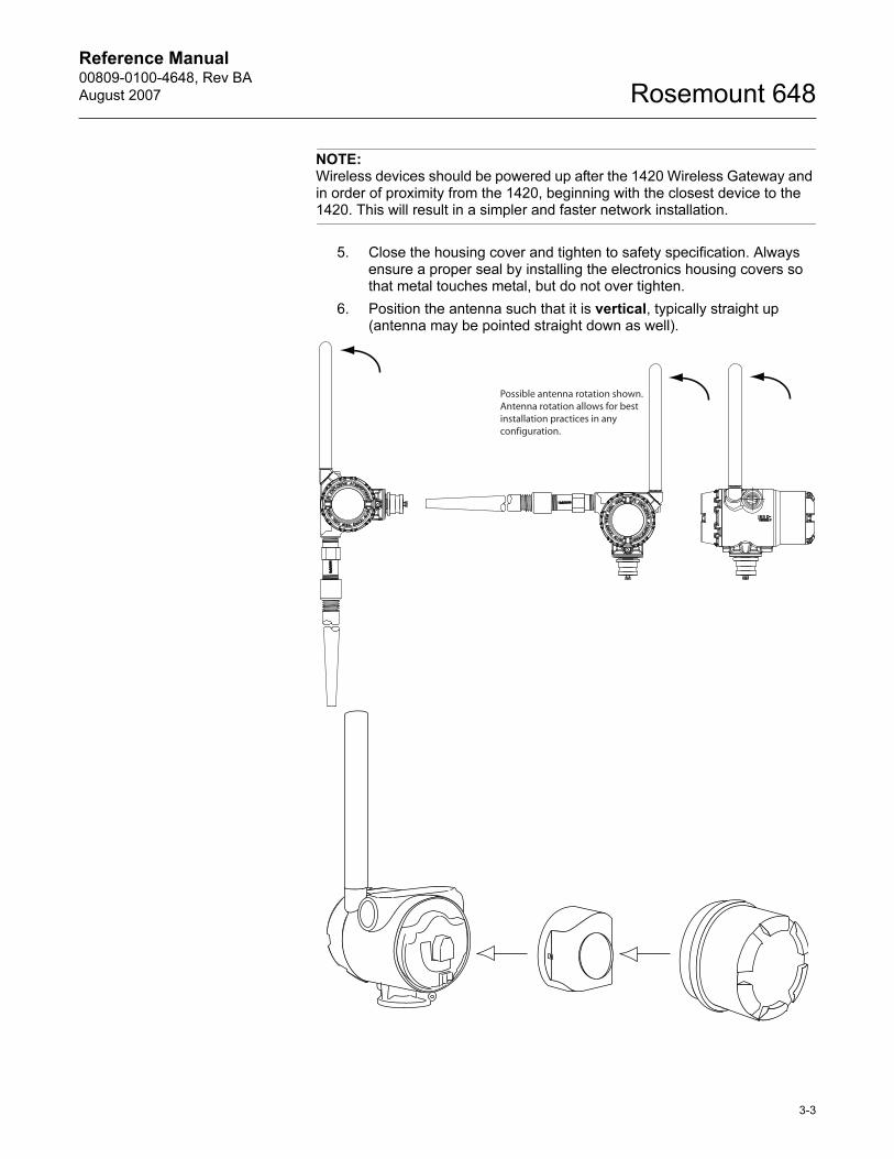
5. Close the housing cover and tighten to safety specification. Always ensure a proper seal by installing the electronics housing covers so that metal touches metal, but do not over tighten.
6. Position the antenna such that it is vertical, typically straight up (antenna may be pointed straight down as well).
Possible antenna rotation shown.Antenna rotation allows for bestinstallation practices in anyconfiguration.
Reference Manual00809-0100-4648, Rev BA
August 2007Rosemount 648
3-4
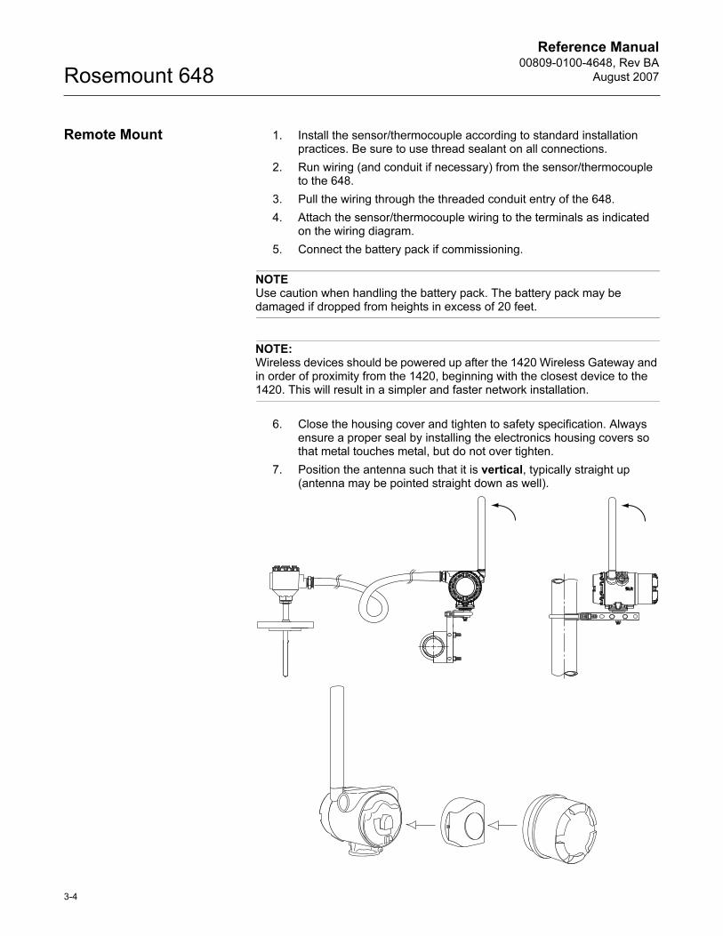
Remote Mount 1. Install the sensor/thermocouple according to standard installation practices. Be sure to use thread sealant on all connections.
2. Run wiring (and conduit if necessary) from the sensor/thermocouple to the 648.
3. Pull the wiring through the threaded conduit entry of the 648.
4. Attach the sensor/thermocouple wiring to the terminals as indicated on the wiring diagram.
5. Connect the battery pack if commissioning.
NOTEUse caution when handling the battery pack. The battery pack may be damaged if dropped from heights in excess of 20 feet.
NOTE:Wireless devices should be powered up after the 1420 Wireless Gateway and in order of proximity from the 1420, beginning with the closest device to the 1420. This will result in a simpler and faster network installation.
6. Close the housing cover and tighten to safety specification. Always ensure a proper seal by installing the electronics housing covers so that metal touches metal, but do not over tighten.
7. Position the antenna such that it is vertical, typically straight up (antenna may be pointed straight down as well).
Reference Manual 00809-0100-4648, Rev BA
August 2007
3-5
Rosemount 648
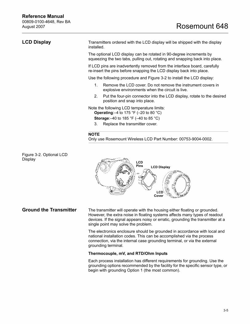
LCD Display Transmitters ordered with the LCD display will be shipped with the display installed.
The optional LCD display can be rotated in 90-degree increments by squeezing the two tabs, pulling out, rotating and snapping back into place.
If LCD pins are inadvertently removed from the interface board, carefully re-insert the pins before snapping the LCD display back into place.
Use the following procedure and Figure 3-2 to install the LCD display:
1. Remove the LCD cover. Do not remove the instrument covers in explosive environments when the circuit is live.
2. Put the four-pin connector into the LCD display, rotate to the desired position and snap into place.
Note the following LCD temperature limits:Operating:–4 to 175 °F (–20 to 80 °C)
Storage:–40 to 185 °F (–40 to 85 °C)
3. Replace the transmitter cover.
NOTEOnly use Rosemount Wireless LCD Part Number: 00753-9004-0002.
Figure 3-2. Optional LCD Display
Ground the Transmitter The transmitter will operate with the housing either floating or grounded. However, the extra noise in floating systems affects many types of readout devices. If the signal appears noisy or erratic, grounding the transmitter at a single point may solve the problem.
The electronics enclosure should be grounded in accordance with local and national installation codes. This can be accomplished via the process connection, via the internal case grounding terminal, or via the external grounding terminal.
Thermocouple, mV, and RTD/Ohm Inputs
Each process installation has different requirements for grounding. Use the grounding options recommended by the facility for the specific sensor type, or begin with grounding Option 1 (the most common).
LCD Display
LCDCover
LCD Pins
Reference Manual00809-0100-4648, Rev BA
August 2007Rosemount 648
3-6
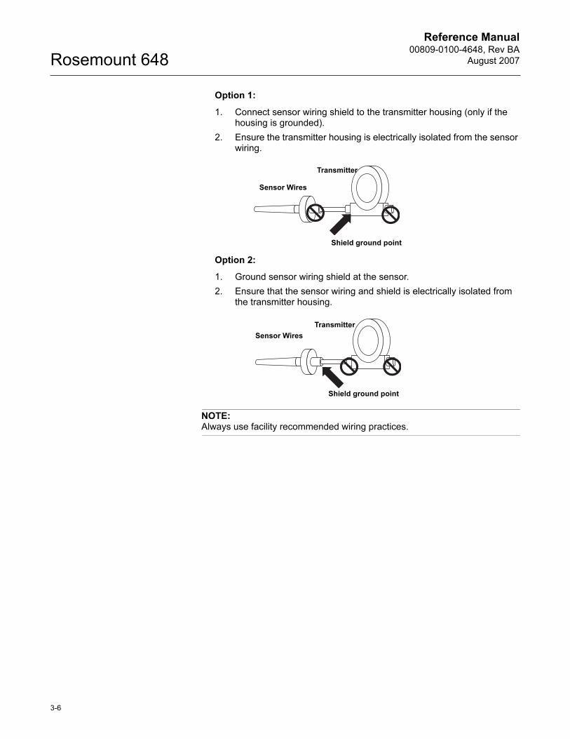
Option 1:
1. Connect sensor wiring shield to the transmitter housing (only if the housing is grounded).
2. Ensure the transmitter housing is electrically isolated from the sensor wiring.
Option 2:
1. Ground sensor wiring shield at the sensor.
2. Ensure that the sensor wiring and shield is electrically isolated from the transmitter housing.
NOTE:Always use facility recommended wiring practices.
Sensor Wires
Shield ground point
Transmitter
Sensor Wires
Shield ground point
Transmitter
Reference Manual 00809-0100-4648, Rev BA
August 2007 Rosemount 648
www.rosemount.com
Section 4 Commissioning
Safety Messages . . . . . . . . . . . . . . . . . . . . . . . . . . . . . . . . . page 4-1
Verify Operation . . . . . . . . . . . . . . . . . . . . . . . . . . . . . . . . . page 4-2
SAFETY MESSAGES Instructions and procedures in this section may require special precautions to ensure the safety of the personnel performing the operations. Information that potentially raises safety issues is indicated by a warning symbol ( ). Please refer to the following safety messages before performing an operation preceded by this symbol.
Warnings
NOTEThe Rosemount 648 and all other wireless devices should be installed only after the 1420 Wireless Gateway has been installed and is functioning properly.Wireless devices should also be powered up in order of proximity from the 1420 Wireless Gateway, beginning with the closest device to the 1420. This will result in a simpler and faster network installation.
Failure to follow these installation guidelines could result in death or
serious injury.
• Make sure only qualified personnel perform the installation.
Explosions could result in death or serious injury.
• Before connecting a 375 Field Communicator in an explosive atmosphere, make
sure the instruments are installed in accordance with intrinsically safe or
non-incendive field wiring practices.
• Verify that the operating atmosphere of the transmitter is consistent with the
appropriate hazardous locations certifications.
Process leaks could result in death or serious injury.
• Do not remove the thermowell while in operation.
• Install and tighten thermowells and sensors before applying pressure
Electrical shock could cause death or serious injury.
• Use extreme caution when making contact with the leads and terminals.
Reference Manual00809-0100-4648, Rev BA
August 2007Rosemount 648
4-2
VERIFY OPERATION Operation can be verified in three locations, at the device via the Local Display, using the 375 Field Communicator, or at the Gateway via the 1420 Wireless Gateway’s integrated web server.
Local Display
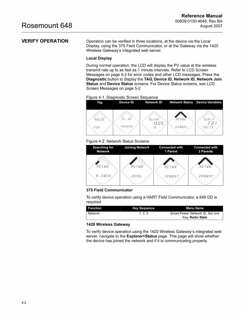
During normal operation, the LCD will display the PV value at the wireless transmit rate up to as fast as 1 minute intervals. Refer to LCD Screen Messages on page 5-2 for error codes and other LCD messages. Press the Diagnostic button to display the TAG, Device ID, Network ID, Network Join Status and Device Status screens. For Device Status screens, see LCD Screen Messages on page 5-2
Figure 4-1. Diagnostic Screen Sequence
Figure 4-2. Network Status Screens
375 Field Communicator
To verify device operation using a HART Field Communicator, a 648 DD is required.
1420 Wireless Gateway
To verify device operation using the 1420 Wireless Gateway’s integrated web server, navigate to the Explorer>Status page. This page will show whether the device has joined the network and if it is communicating properly.
Tag Device ID Network ID Network Status Device Variables
Searching for
Network
Joining Network Connected with
1 Parent
Connected with
2 Parents
Function Key Sequence Menu Items
Network 1, 3, 3 Smart Power, Network ID, Set Join
Key, Radio State
A b c d e
f g h
i d - X X
X X X X X X
n e t w k
13 0 5 I D
n e t w k
2 p a r n t
S u p l y
7. 2 1v o l t s
n e t w k
a - s r c h
n e t w k
j o i n g
n e t w k
1 p a r n t
n e t w k
2 p a r n t
Reference Manual 00809-0100-4648, Rev BA
August 2007
4-3
Rosemount 648
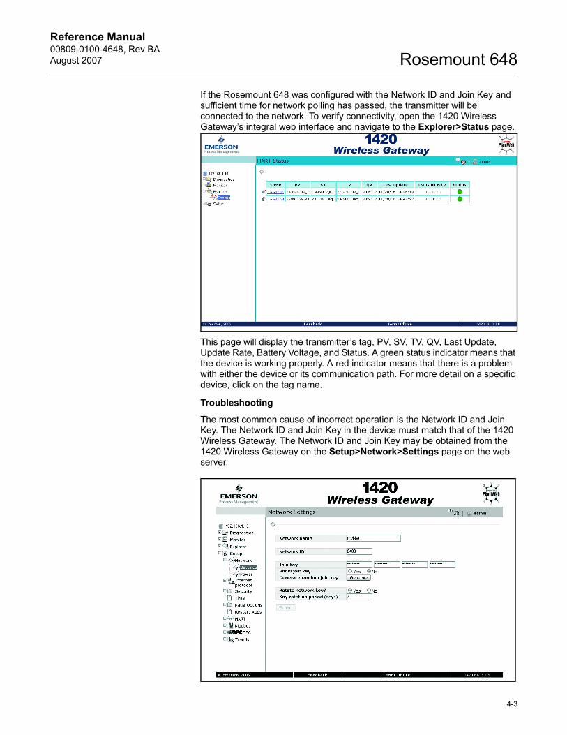
If the Rosemount 648 was configured with the Network ID and Join Key and sufficient time for network polling has passed, the transmitter will be connected to the network. To verify connectivity, open the 1420 Wireless Gateway’s integral web interface and navigate to the Explorer>Status page.
This page will display the transmitter’s tag, PV, SV, TV, QV, Last Update, Update Rate, Battery Voltage, and Status. A green status indicator means that the device is working properly. A red indicator means that there is a problem with either the device or its communication path. For more detail on a specific device, click on the tag name.
Troubleshooting
The most common cause of incorrect operation is the Network ID and Join Key. The Network ID and Join Key in the device must match that of the 1420 Wireless Gateway. The Network ID and Join Key may be obtained from the 1420 Wireless Gateway on the Setup>Network>Settings page on the web server.

Reference Manual00809-0100-4648, Rev BA
August 2007Rosemount 648
4-4
Reference Manual 00809-0100-4648, Rev BA
August 2007 Rosemount 648
www.rosemount.com
Section 5 Operation and Maintenance
Safety Messages . . . . . . . . . . . . . . . . . . . . . . . . . . . . . . . . . page 5-1
LCD Screen Messages . . . . . . . . . . . . . . . . . . . . . . . . . . . . page 5-2
Battery Replacement . . . . . . . . . . . . . . . . . . . . . . . . . . . . . page 5-9
SAFETY MESSAGES Instructions and procedures in this section may require special precautions to ensure the safety of the personnel performing the operations. Information that potentially raises safety issues is indicated by a warning symbol ( ). Please refer to the following safety messages before performing an operation preceded by this symbol.
Warnings
Failure to follow these installation guidelines could result in death or
serious injury.
• Make sure only qualified personnel perform the installation.
Explosions could result in death or serious injury.
• Before connecting a 375 Field Communicator in an explosive atmosphere, make
sure the instruments are installed in accordance with intrinsically safe or
non-incendive field wiring practices.
• Verify that the operating atmosphere of the transmitter is consistent with the
appropriate hazardous locations certifications.
Process leaks could result in death or serious injury.
• Do not remove the thermowell while in operation.
• Install and tighten thermowells and sensors before applying pressure
Electrical shock could cause death or serious injury.
• Use extreme caution when making contact with the leads and terminals.
Reference Manual00809-0100-4648, Rev BA
August 2007Rosemount 648
5-2
LCD SCREEN MESSAGES
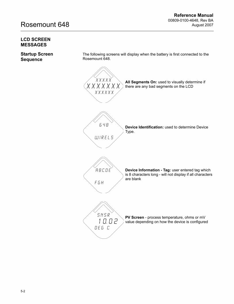
Startup Screen Sequence
The following screens will display when the battery is first connected to the Rosemount 648.
All Segments On: used to visually determine if there are any bad segments on the LCD
Device Identification: used to determine Device Type.
Device Information - Tag: user entered tag which is 8 characters long - will not display if all characters are blank
PV Screen - process temperature, ohms or mV value depending on how the device is configured
X X X X X
X X X X x x xx x x x x x
6 4 8
W I r e l s
A b c d e
f g h
s n s r
1 0. 0 2d e g c
Reference Manual 00809-0100-4648, Rev BA
August 2007
5-3
Rosemount 648
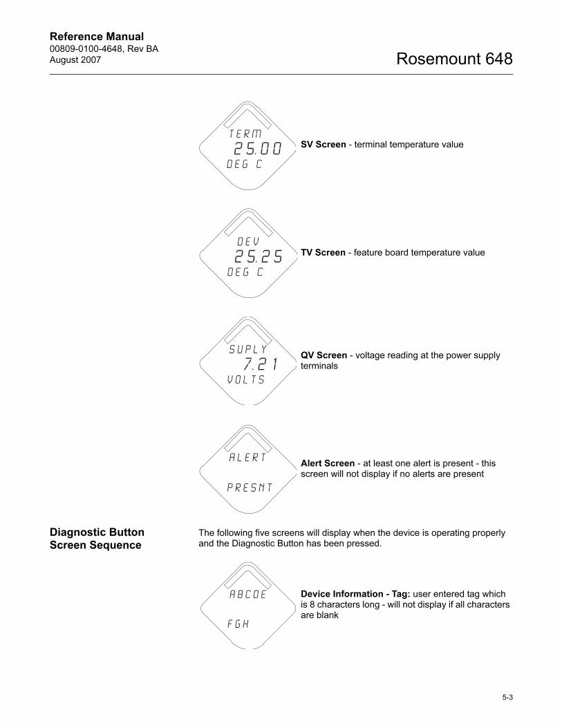
Diagnostic Button Screen Sequence
The following five screens will display when the device is operating properly and the Diagnostic Button has been pressed.
SV Screen - terminal temperature value
TV Screen - feature board temperature value
QV Screen - voltage reading at the power supply terminals
Alert Screen - at least one alert is present - this screen will not display if no alerts are present
T E R M
2 5. 0 0d e g c
D E V
2 5. 2 5d e g c
S u p l y
7. 2 1v o l t s
a l e r t
p r e s n t
Device Information - Tag: user entered tag which is 8 characters long - will not display if all characters are blank
A b c d e
f g h
Reference Manual00809-0100-4648, Rev BA
August 2007Rosemount 648
5-4
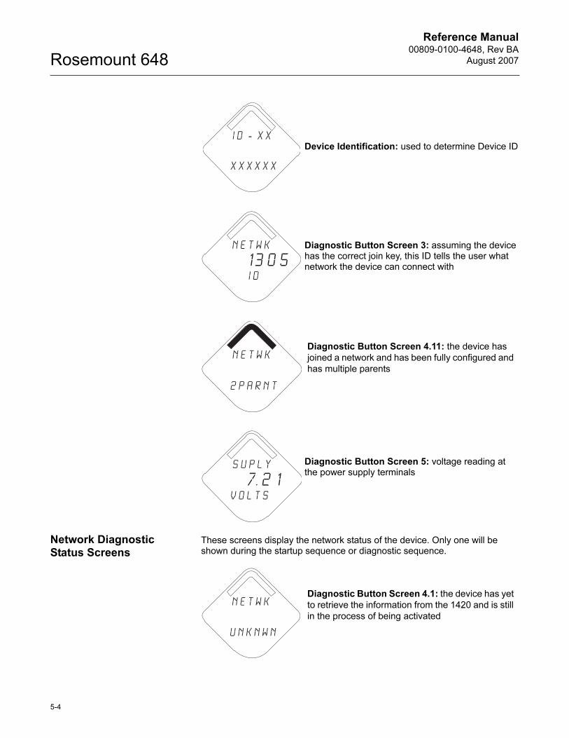
Network Diagnostic Status Screens
These screens display the network status of the device. Only one will be shown during the startup sequence or diagnostic sequence.
Device Identification: used to determine Device ID
Diagnostic Button Screen 3: assuming the device has the correct join key, this ID tells the user what network the device can connect with
Diagnostic Button Screen 4.11: the device has
joined a network and has been fully configured and
has multiple parents
Diagnostic Button Screen 5: voltage reading at the power supply terminals
i d - X X
X X X X X X
n e t w k
13 0 5 I D
n e t w k
2 p a r n t
S u p l y
7. 2 1v o l t s
Diagnostic Button Screen 4.1: the device has yet
to retrieve the information from the 1420 and is still
in the process of being activated
n e t w k
u n k n w n
Reference Manual 00809-0100-4648, Rev BA
August 2007
5-5
Rosemount 648
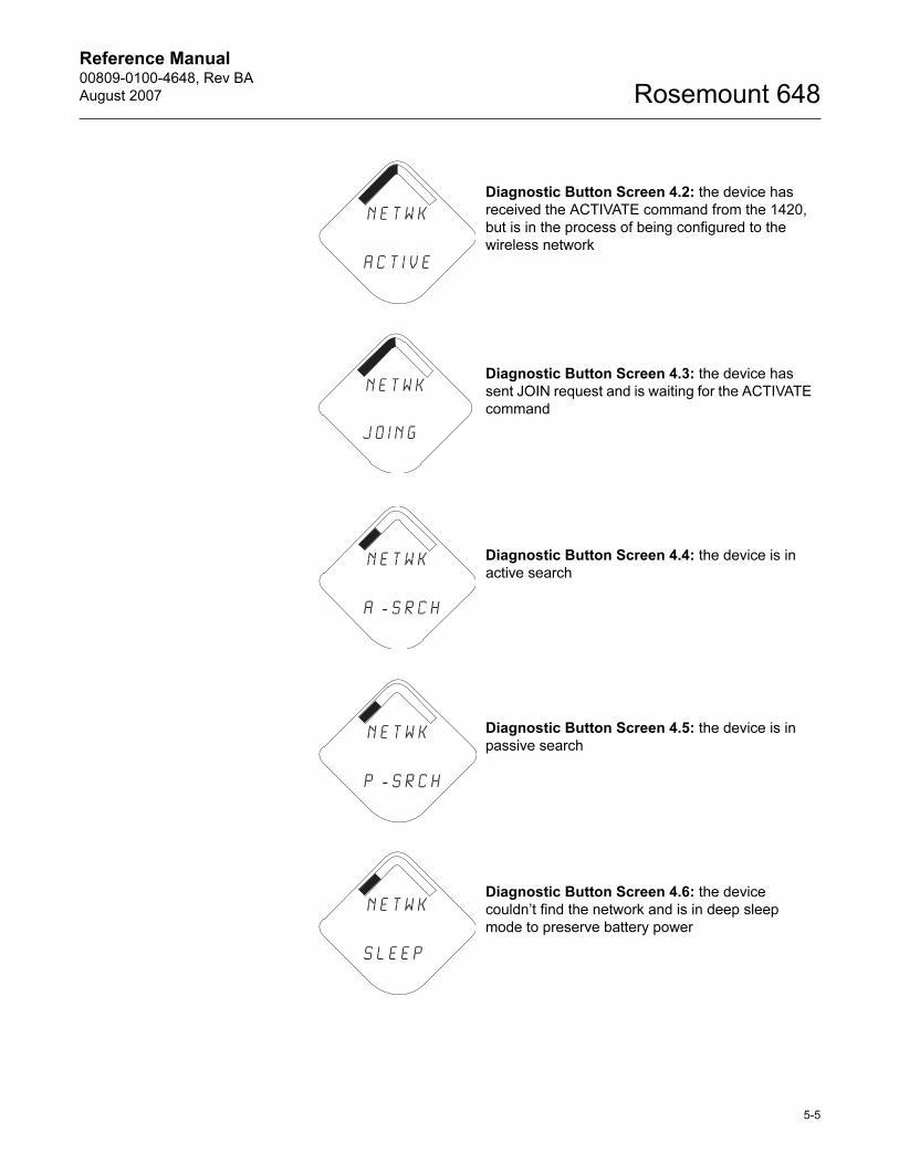
Diagnostic Button Screen 4.2: the device has
received the ACTIVATE command from the 1420,
but is in the process of being configured to the
wireless network
Diagnostic Button Screen 4.3: the device has
sent JOIN request and is waiting for the ACTIVATE
command
Diagnostic Button Screen 4.4: the device is in
active search
Diagnostic Button Screen 4.5: the device is in
passive search
Diagnostic Button Screen 4.6: the device
couldn’t find the network and is in deep sleep
mode to preserve battery power
n e t w k
a c t i v e
n e t w k
j o i n g
n e t w k
a - s r c h
n e t w k
p - s r c h
n e t w k
s l e e p
Reference Manual00809-0100-4648, Rev BA
August 2007Rosemount 648
5-6
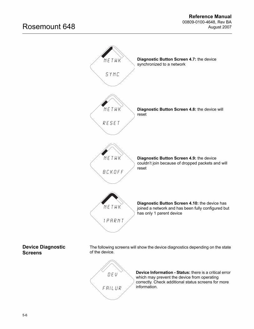
Device Diagnostic Screens
The following screens will show the device diagnostics depending on the state of the device.
Diagnostic Button Screen 4.7: the device
synchronized to a network
Diagnostic Button Screen 4.8: the device will
reset
Diagnostic Button Screen 4.9: the device
couldn’t join because of dropped packets and will
reset
Diagnostic Button Screen 4.10: the device has
joined a network and has been fully configured but
has only 1 parent device
n e t w k
s y n c
n e t w k
r e s e t
n e t w k
b c k o f f
n e t w k
1 p a r n t
Device Information - Status: there is a critical error which may prevent the device from operating correctly. Check additional status screens for more information.
D E V
f A i l u r
Reference Manual 00809-0100-4648, Rev BA
August 2007
5-7
Rosemount 648
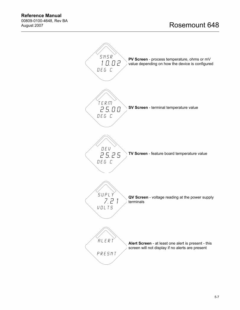
PV Screen - process temperature, ohms or mV value depending on how the device is configured
SV Screen - terminal temperature value
TV Screen - feature board temperature value
QV Screen - voltage reading at the power supply terminals
Alert Screen - at least one alert is present - this screen will not display if no alerts are present
s n s r
1 0. 0 2d e g c
T E R M
2 5. 0 0d e g c
D E V
2 5. 2 5d e g c
S u p l y
7. 2 1v o l t s
a l e r t
p r e s n t
Reference Manual00809-0100-4648, Rev BA
August 2007Rosemount 648
5-8
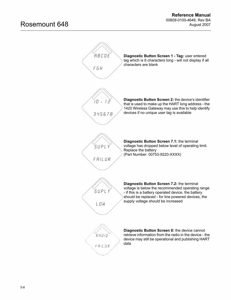
Diagnostic Button Screen 1 - Tag: user entered tag which is 8 characters long - will not display if all characters are blank
Diagnostic Button Screen 2: the device’s identifier that is used to make up the HART long address - the 1420 Wireless Gateway may use this to help identify devices if no unique user tag is available
Diagnostic Button Screen 7.1: the terminal voltage has dropped below level of operating limit. Replace the battery (Part Number: 00753-9220-XXXX)
Diagnostic Button Screen 7.2: the terminal voltage is below the recommended operating range - if this is a battery operated device, the battery should be replaced - for line powered devices, the supply voltage should be increased
Diagnostic Button Screen 8: the device cannot retrieve information from the radio in the device - the device may still be operational and publishing HART data
A b c d e
f g h
i d - 1 2
3 4 5 6 7 8
s u p l y
f a i l u r
s u p l y
l o w
Reference Manual 00809-0100-4648, Rev BA
August 2007
5-9
Rosemount 648
NOTEUse the Rosemount Wireless LCD Part Number: 00753-9004-0002.
BATTERY REPLACEMENT
Expected battery life is eight years at reference conditions.(1)
When battery replacement is required, remove the battery cover and remove the battery pack. Replace the pack (part number 00753-9220-XXXX) and replace the cover. Tighten to specification and verify operation.
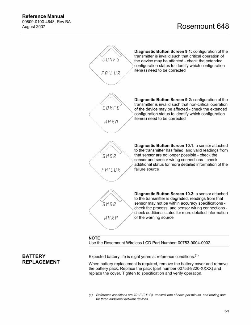
Diagnostic Button Screen 9.1: configuration of the transmitter is invalid such that critical operation of the device may be affected - check the extended configuration status to identify which configuration item(s) need to be corrected
Diagnostic Button Screen 9.2: configuration of the transmitter is invalid such that non-critical operation of the device may be affected - check the extended configuration status to identify which configuration item(s) need to be corrected
Diagnostic Button Screen 10.1: a sensor attached to the transmitter has failed, and valid readings from that sensor are no longer possible - check the sensor and sensor wiring connections - check additional status for more detailed information of the failure source
Diagnostic Button Screen 10.2: a sensor attached to the transmitter is degraded, readings from that sensor may not be within accuracy specifications - check the process, and sensor wiring connections - check additional status for more detailed information of the warning source
c o n f g
f a i l u r
c o n f g
w a r n
s n s r
f a i l u r
s n s r
w a r n
(1) Reference conditions are 70° F (21° C), transmit rate of once per minute, and routing data
for three additional network devices.
Reference Manual00809-0100-4648, Rev BA
August 2007Rosemount 648
5-10
Handling Considerations
The battery pack with the wireless unit contains 2 “C” size primary lithium/thionyl chloride batteries. Each battery contains approximately 2.5 grams of lithium, for a total of 5 grams in each pack. Under normal conditions, the battery materials are self-contained and are not reactive as long as the batteries and the battery pack integrity are maintained. Care should be taken to prevent thermal, electrical or mechanical damage. Contacts should be protected to prevent premature discharge.
Use caution when handling the battery pack. The battery pack may be damaged if dropped from heights in excess of 20 feet.
Battery hazards remain when cells are discharged.
Environmental Considerations
As with any battery, local environmental rules and regulations should be consulted for proper management of spent batteries. If no specific requirements exist, recycling through a qualified recycler is encouraged. Consult the materials safety data sheet for battery specific information.
Shipping Considerations
The unit is shipped to you without the battery installed. Unless specifically instructed to do otherwise, remover the battery pack from the unit prior to shipping.
Primary lithium batteries are regulated in transportation by the U.S. Department of Transportation, and are also covered by International Air Transport Association (IATA), International Civil Aviation Organization (ICAO), and European Ground Transportation of Dangerous Goods (ARD). It is the responsibility of the shipper to ensure compliance with these or any other local requirements. Please consult current regulations and requirements before shipping.
Reference Manual 00809-0100-4648, Rev BA
August 2007 Rosemount 648
www.rosemount.com
Appendix A Specifications and Reference Data
Specifications . . . . . . . . . . . . . . . . . . . . . . . . . . . . . . . . . . . page A-1
Dimensional Drawings . . . . . . . . . . . . . . . . . . . . . . . . . . . . page A-5
Ordering Information . . . . . . . . . . . . . . . . . . . . . . . . . . . . . page A-6
SPECIFICATIONS
Functional Specifications
Input
Supports Thermocouple, RTD, millivolt and ohm input types. See Accuracy on
page A-3 for sensor options.
Output
Wireless enabled, linear with temperature or input.
Local Display
The optional five-digit integral LCD Display can display engineering units (°F,
°C, °R, K, Ω, and millivolts). Display updates at transmit rate up to once per
minute.
Humidity Limits
0–100% relative humidity
Transmit Rate
User selectable, 15 sec. to 60 min.
Accuracy
(PT 100 @ reference conditions: 20 °C)
±0.45 °C (±0.81 °F)
Physical Specifications Electrical Connections / Battery
• Replaceable, non-rechargeable, Intrinsically Safe Lithium-Thionyl Chloride battery pack with PBT enclosure.
• Eight year battery life at reference conditions.(1)
• 4 Screw Terminals for sensor connection.
Field Communicator Connections
Communication Terminals
Clips permanently fixed to terminal block
(1) Reference conditions are 70° F (21° C), transmit rate of once per minute, and routing data
for three additional network devices.
Reference Manual00809-0100-4648, Rev BA
August 2007Rosemount 648
A-2
Materials of Construction
Enclosure
Housing
• Low-copper aluminum
Paint
• Polyurethane
Cover O-ring
• Buna-N
Terminal Block and Battery Pack
• PBT
Antenna
• PBT/PC integrated omnidirectional antenna
Mounting
Transmitters may be attached directly to the sensor. Mounting brackets also
permit remote mounting. See “Dimensional Drawings” on page A-5.
Weight
648 without LCD - 4.6 lbs. (2 kg)
648 with M5 LCD - 4.7 lbs (2.1 kg)
Enclosure Ratings (648)
Housing option code D is NEMA 4X, and IP66.
Performance Specifications
EMC (ElectroMagnetic Compatibility)
The 648 meets all requirements listed under IEC 61326.
Transmitter Stability
The 648 has a stability of ±0.3% of output reading or 0.3 °C (whichever is
greater) for 24 months
Self Calibration
The analog-to-digital measurement circuitry automatically self-calibrates for
each temperature update by comparing the dynamic measurement
to extremely stable and accurate internal reference elements.
Vibration Effect
Less than ±0.1% of URL when tested per the requirements of IEC60770-1
field with general application or pipeline with low vibration level (10-60 Hz
0.15 mm displacement peak amplitude/60-500 Hz 2g).
Reference Manual 00809-0100-4648, Rev BA
August 2007
A-3
Rosemount 648
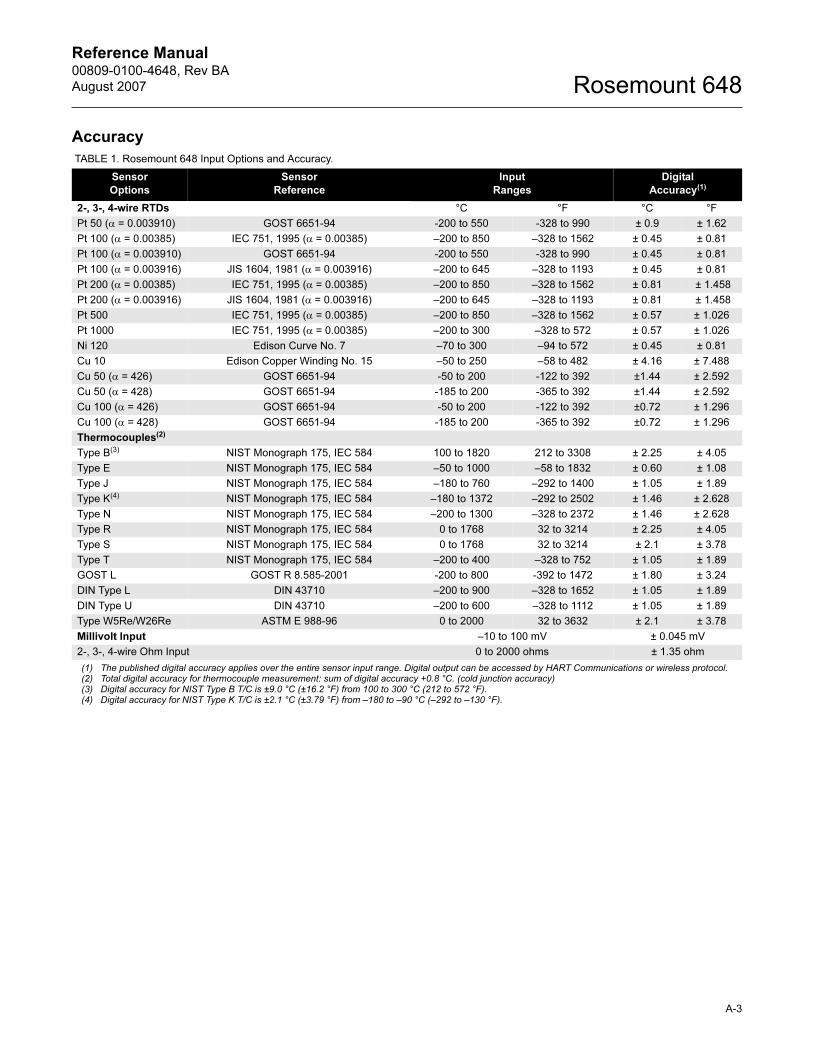
Accuracy
TABLE 1. Rosemount 648 Input Options and Accuracy.
Sensor
Options
Sensor
Reference
Input
Ranges
Digital
Accuracy(1)
2-, 3-, 4-wire RTDs °C °F °C °F
Pt 50 (α = 0.003910) GOST 6651-94 -200 to 550 -328 to 990 ± 0.9 ± 1.62
Pt 100 (α = 0.00385) IEC 751, 1995 (α = 0.00385) –200 to 850 –328 to 1562 ± 0.45 ± 0.81
Pt 100 (α = 0.003910) GOST 6651-94 -200 to 550 -328 to 990 ± 0.45 ± 0.81
Pt 100 (α = 0.003916) JIS 1604, 1981 (α = 0.003916) –200 to 645 –328 to 1193 ± 0.45 ± 0.81
Pt 200 (α = 0.00385) IEC 751, 1995 (α = 0.00385) –200 to 850 –328 to 1562 ± 0.81 ± 1.458
Pt 200 (α = 0.003916) JIS 1604, 1981 (α = 0.003916) –200 to 645 –328 to 1193 ± 0.81 ± 1.458
Pt 500 IEC 751, 1995 (α = 0.00385) –200 to 850 –328 to 1562 ± 0.57 ± 1.026
Pt 1000 IEC 751, 1995 (α = 0.00385) –200 to 300 –328 to 572 ± 0.57 ± 1.026
Ni 120 Edison Curve No. 7 –70 to 300 –94 to 572 ± 0.45 ± 0.81
Cu 10 Edison Copper Winding No. 15 –50 to 250 –58 to 482 ± 4.16 ± 7.488
Cu 50 (α = 426) GOST 6651-94 -50 to 200 -122 to 392 ±1.44 ± 2.592
Cu 50 (α = 428) GOST 6651-94 -185 to 200 -365 to 392 ±1.44 ± 2.592
Cu 100 (α = 426) GOST 6651-94 -50 to 200 -122 to 392 ±0.72 ± 1.296
Cu 100 (α = 428) GOST 6651-94 -185 to 200 -365 to 392 ±0.72 ± 1.296
Thermocouples(2)
Type B(3) NIST Monograph 175, IEC 584 100 to 1820 212 to 3308 ± 2.25 ± 4.05
Type E NIST Monograph 175, IEC 584 –50 to 1000 –58 to 1832 ± 0.60 ± 1.08
Type J NIST Monograph 175, IEC 584 –180 to 760 –292 to 1400 ± 1.05 ± 1.89
Type K(4) NIST Monograph 175, IEC 584 –180 to 1372 –292 to 2502 ± 1.46 ± 2.628
Type N NIST Monograph 175, IEC 584 –200 to 1300 –328 to 2372 ± 1.46 ± 2.628
Type R NIST Monograph 175, IEC 584 0 to 1768 32 to 3214 ± 2.25 ± 4.05
Type S NIST Monograph 175, IEC 584 0 to 1768 32 to 3214 ± 2.1 ± 3.78
Type T NIST Monograph 175, IEC 584 –200 to 400 –328 to 752 ± 1.05 ± 1.89
GOST L GOST R 8.585-2001 -200 to 800 -392 to 1472 ± 1.80 ± 3.24
DIN Type L DIN 43710 –200 to 900 –328 to 1652 ± 1.05 ± 1.89
DIN Type U DIN 43710 –200 to 600 –328 to 1112 ± 1.05 ± 1.89
Type W5Re/W26Re ASTM E 988-96 0 to 2000 32 to 3632 ± 2.1 ± 3.78
Millivolt Input –10 to 100 mV ± 0.045 mV
2-, 3-, 4-wire Ohm Input 0 to 2000 ohms ± 1.35 ohm
(1) The published digital accuracy applies over the entire sensor input range. Digital output can be accessed by HART Communications or wireless protocol.(2) Total digital accuracy for thermocouple measurement: sum of digital accuracy +0.8 °C. (cold junction accuracy)(3) Digital accuracy for NIST Type B T/C is ±9.0 °C (±16.2 °F) from 100 to 300 °C (212 to 572 °F).(4) Digital accuracy for NIST Type K T/C is ±2.1 °C (±3.79 °F) from –180 to –90 °C (–292 to –130 °F).
Reference Manual00809-0100-4648, Rev BA
August 2007Rosemount 648
A-4
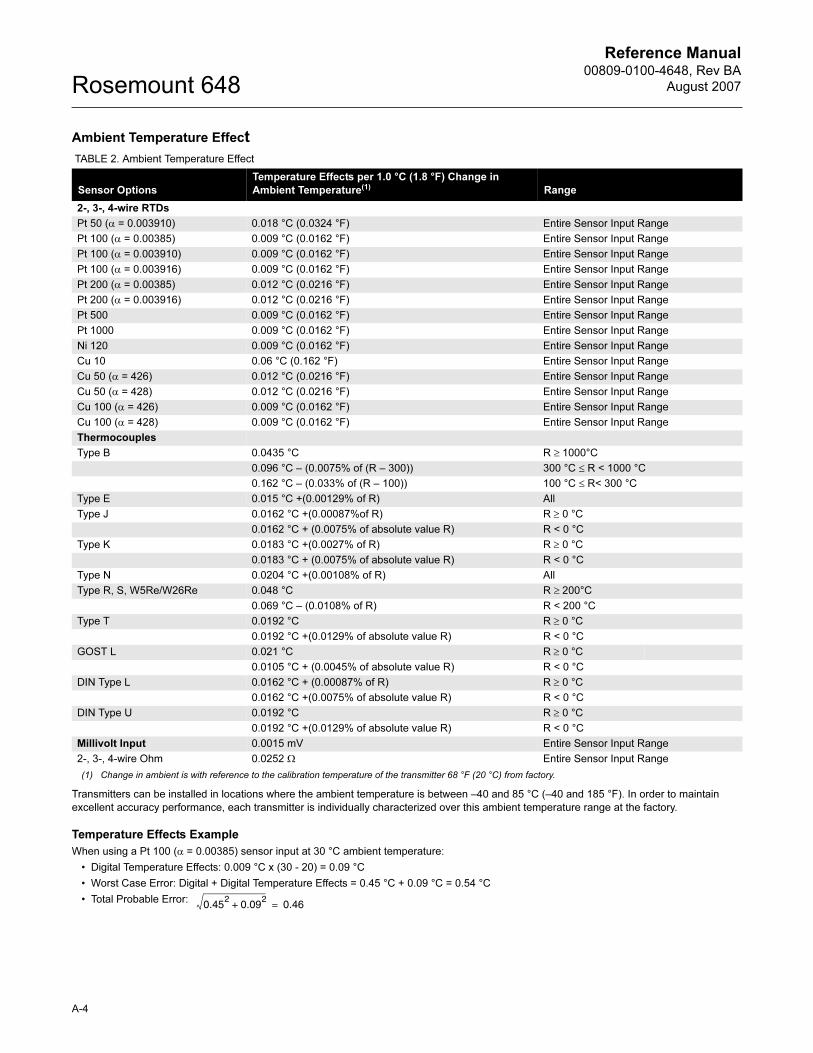
Ambient Temperature Effect
Transmitters can be installed in locations where the ambient temperature is between –40 and 85 °C (–40 and 185 °F). In order to maintain
excellent accuracy performance, each transmitter is individually characterized over this ambient temperature range at the factory.
Temperature Effects Example
When using a Pt 100 (α = 0.00385) sensor input at 30 °C ambient temperature:
• Digital Temperature Effects: 0.009 °C x (30 - 20) = 0.09 °C
• Worst Case Error: Digital + Digital Temperature Effects = 0.45 °C + 0.09 °C = 0.54 °C
• Total Probable Error:
TABLE 2. Ambient Temperature Effect
Sensor Options
Temperature Effects per 1.0 °C (1.8 °F) Change in
Ambient Temperature(1) Range
2-, 3-, 4-wire RTDs
Pt 50 (α = 0.003910) 0.018 °C (0.0324 °F) Entire Sensor Input Range
Pt 100 (α = 0.00385) 0.009 °C (0.0162 °F) Entire Sensor Input Range
Pt 100 (α = 0.003910) 0.009 °C (0.0162 °F) Entire Sensor Input Range
Pt 100 (α = 0.003916) 0.009 °C (0.0162 °F) Entire Sensor Input Range
Pt 200 (α = 0.00385) 0.012 °C (0.0216 °F) Entire Sensor Input Range
Pt 200 (α = 0.003916) 0.012 °C (0.0216 °F) Entire Sensor Input Range
Pt 500 0.009 °C (0.0162 °F) Entire Sensor Input Range
Pt 1000 0.009 °C (0.0162 °F) Entire Sensor Input Range
Ni 120 0.009 °C (0.0162 °F) Entire Sensor Input Range
Cu 10 0.06 °C (0.162 °F) Entire Sensor Input Range
Cu 50 (α = 426) 0.012 °C (0.0216 °F) Entire Sensor Input Range
Cu 50 (α = 428) 0.012 °C (0.0216 °F) Entire Sensor Input Range
Cu 100 (α = 426) 0.009 °C (0.0162 °F) Entire Sensor Input Range
Cu 100 (α = 428) 0.009 °C (0.0162 °F) Entire Sensor Input Range
Thermocouples
Type B 0.0435 °C R ≥ 1000°C
0.096 °C – (0.0075% of (R – 300)) 300 °C ≤ R < 1000 °C
0.162 °C – (0.033% of (R – 100)) 100 °C ≤ R< 300 °C
Type E 0.015 °C +(0.00129% of R) All
Type J 0.0162 °C +(0.00087%of R) R ≥ 0 °C
0.0162 °C + (0.0075% of absolute value R) R < 0 °C
Type K 0.0183 °C +(0.0027% of R) R ≥ 0 °C
0.0183 °C + (0.0075% of absolute value R) R < 0 °C
Type N 0.0204 °C +(0.00108% of R) All
Type R, S, W5Re/W26Re 0.048 °C R ≥ 200°C
0.069 °C – (0.0108% of R) R < 200 °C
Type T 0.0192 °C R ≥ 0 °C
0.0192 °C +(0.0129% of absolute value R) R < 0 °C
GOST L 0.021 °C R ≥ 0 °C
0.0105 °C + (0.0045% of absolute value R) R < 0 °C
DIN Type L 0.0162 °C + (0.00087% of R) R ≥ 0 °C
0.0162 °C +(0.0075% of absolute value R) R < 0 °C
DIN Type U 0.0192 °C R ≥ 0 °C
0.0192 °C +(0.0129% of absolute value R) R < 0 °C
Millivolt Input 0.0015 mV Entire Sensor Input Range
2-, 3-, 4-wire Ohm 0.0252 Ω Entire Sensor Input Range
(1) Change in ambient is with reference to the calibration temperature of the transmitter 68 °F (20 °C) from factory.
0.452
0.092
+ 0.46=
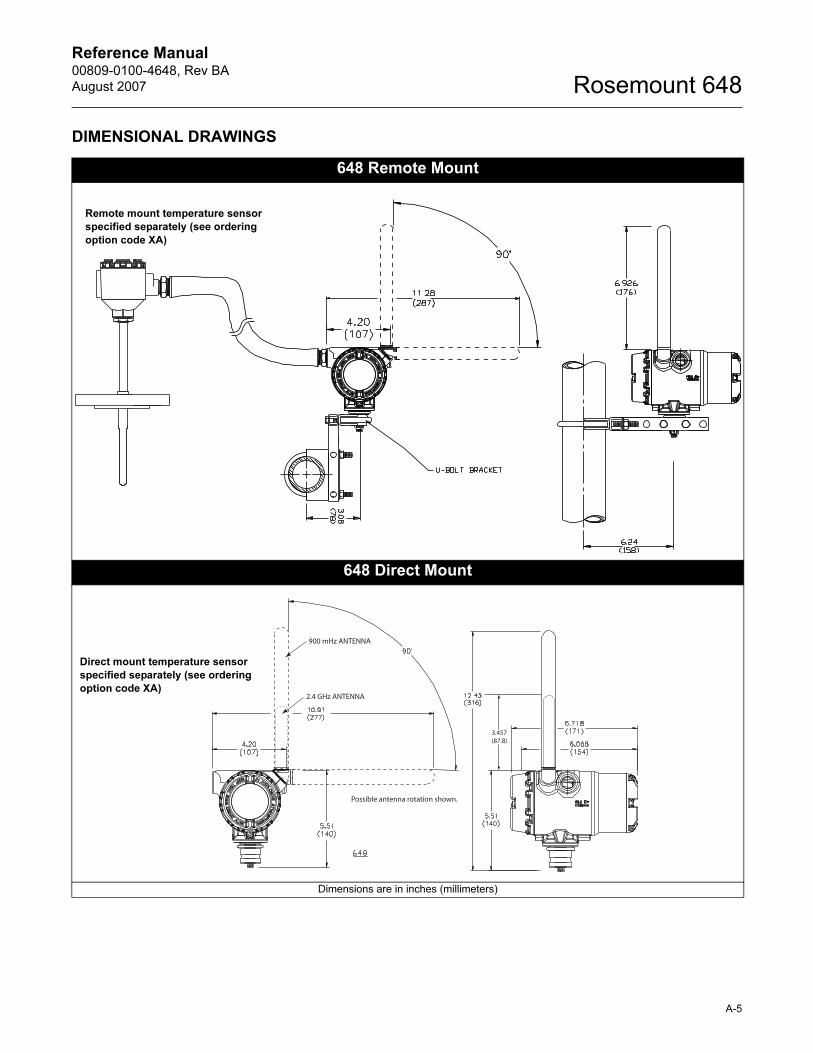
Reference Manual 00809-0100-4648, Rev BA
August 2007
A-5
Rosemount 648
DIMENSIONAL DRAWINGS
648 Remote Mount
648 Direct Mount
Dimensions are in inches (millimeters)
Remote mount temperature sensor
specified separately (see ordering
option code XA)
Possible antenna rotation shown.
900 mHz ANTENNA
2.4 GHz ANTENNA
3.457(87.8)
Direct mount temperature sensor
specified separately (see ordering
option code XA)
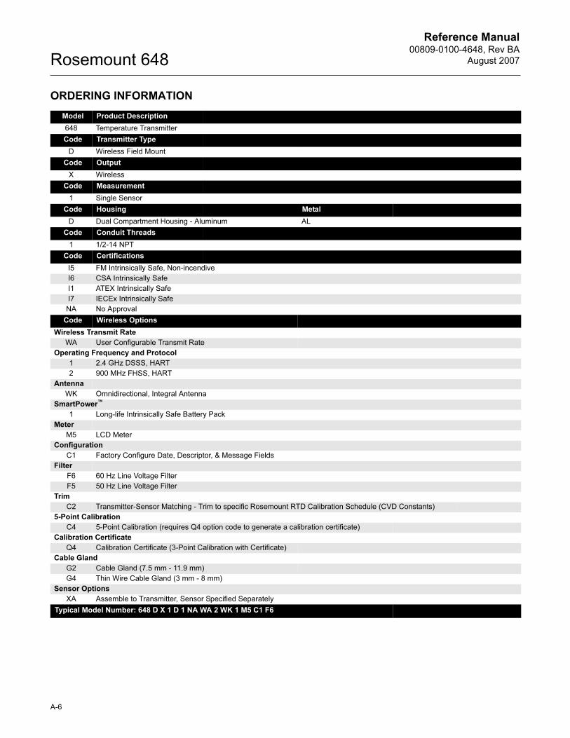
Reference Manual00809-0100-4648, Rev BA
August 2007Rosemount 648
A-6
ORDERING INFORMATION
Model Product Description
648 Temperature Transmitter
Code Transmitter Type
D Wireless Field Mount
Code Output
X Wireless
Code Measurement
1 Single Sensor
Code Housing Metal
D Dual Compartment Housing - Aluminum AL
Code Conduit Threads
1 1/2-14 NPT
Code Certifications
I5 FM Intrinsically Safe, Non-incendive
I6 CSA Intrinsically Safe
I1 ATEX Intrinsically Safe
I7 IECEx Intrinsically Safe
NA No Approval
Code Wireless Options
Wireless Transmit Rate
WA User Configurable Transmit Rate
Operating Frequency and Protocol
1 2.4 GHz DSSS, HART
2 900 MHz FHSS, HART
Antenna
WK Omnidirectional, Integral Antenna
SmartPower™
1 Long-life Intrinsically Safe Battery Pack
Meter
M5 LCD Meter
Configuration
C1 Factory Configure Date, Descriptor, & Message Fields
Filter
F6 60 Hz Line Voltage Filter
F5 50 Hz Line Voltage Filter
Trim
C2 Transmitter-Sensor Matching - Trim to specific Rosemount RTD Calibration Schedule (CVD Constants)
5-Point Calibration
C4 5-Point Calibration (requires Q4 option code to generate a calibration certificate)
Calibration Certificate
Q4 Calibration Certificate (3-Point Calibration with Certificate)
Cable Gland
G2 Cable Gland (7.5 mm - 11.9 mm)
G4 Thin Wire Cable Gland (3 mm - 8 mm)
Sensor Options
XA Assemble to Transmitter, Sensor Specified Separately
Typical Model Number: 648 D X 1 D 1 NA WA 2 WK 1 M5 C1 F6
Reference Manual 00809-0100-4648, Rev BA
August 2007 Rosemount 648
www.rosemount.com
Appendix B Product Certifications
Approved Manufacturing Locations . . . . . . . . . . . . . . . . . page B-1
Telecommunication Compliance . . . . . . . . . . . . . . . . . . . . page B-1
European Union Directive Information . . . . . . . . . . . . . . . page B-1
Ordinary Location Certification for FM . . . . . . . . . . . . . . . page B-2
Hazardous Locations Certificates . . . . . . . . . . . . . . . . . . . page B-2
Approved Manufacturing Locations
Rosemount Inc. - Chanhassen, Minnesota, USA
Emerson Process Management GmbH & Co. - Karlstein, Germany
Emerson Process Management Asia Pacific Private Limited - Singapore
Telecommunication Compliance
All wireless devices require certification to ensure that they adhere to
regulations regarding the use of the RF spectrum. Nearly every country
requires this type of product certification. Emerson is working with
governmental agencies around the world to supply fully compliant products
and remove the risk of violating country directives or laws governing wireless
device usage. To see which countries our devices have received certification
for use in, see www.rosemount.com/smartwireless.
FCC and IC This device complies with Part 15 of the FCC Rules. Operation is subject to the following conditions: This device may not cause harmful interference, this device must accept any interference received, including interference that may cause undesired operation.
This device must be installed to ensure a minimum antenna separation distance of 20 cm from all persons.
European Union Directive Information
The EC declaration of conformity for all applicable European directives for this product can be found on the Rosemount website at www.rosemount.com. A hard copy may be obtained by contacting your local sales representative.
ATEX Directive (94/9/EC)Emerson Process Management complies with the ATEX Directive.
Electro Magnetic Compatibility (EMC) (89/336/EEC)EN 50081-1: 1992; EN 50082-2: 1995;EN 61326-1: 1997 — Industrial
Radio and Telecommunications Terminal Equipment Directive (R&TTE) (1999/5/EC)
Emerson Process Management complies with the R&TTE Directive.
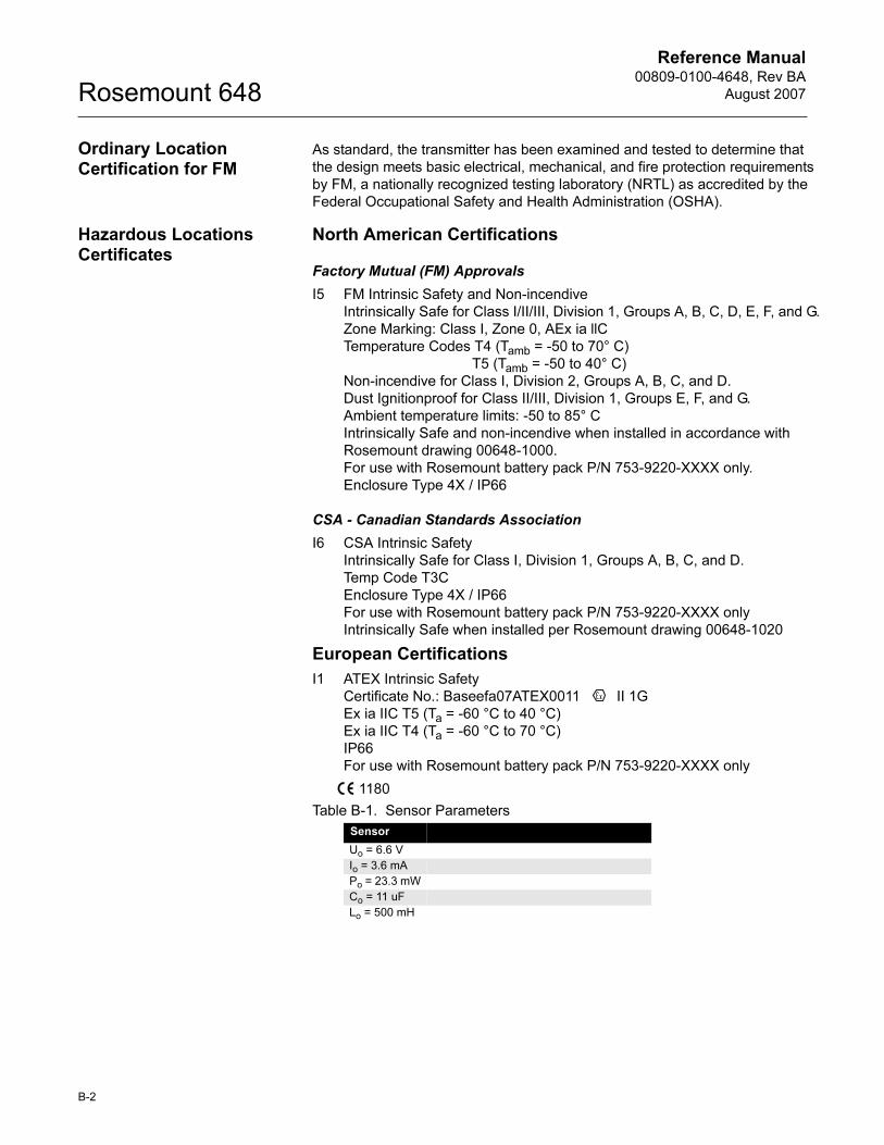
Reference Manual00809-0100-4648, Rev BA
August 2007Rosemount 648
B-2
Ordinary Location Certification for FM
As standard, the transmitter has been examined and tested to determine that
the design meets basic electrical, mechanical, and fire protection requirements
by FM, a nationally recognized testing laboratory (NRTL) as accredited by the
Federal Occupational Safety and Health Administration (OSHA).
Hazardous Locations Certificates
North American Certifications
Factory Mutual (FM) Approvals
I5 FM Intrinsic Safety and Non-incendive
Intrinsically Safe for Class I/II/III, Division 1, Groups A, B, C, D, E, F, and G.
Zone Marking: Class I, Zone 0, AEx ia llC
Temperature Codes T4 (Tamb = -50 to 70° C)
T5 (Tamb = -50 to 40° C)
Non-incendive for Class I, Division 2, Groups A, B, C, and D.
Dust Ignitionproof for Class II/III, Division 1, Groups E, F, and G.
Ambient temperature limits: -50 to 85° C
Intrinsically Safe and non-incendive when installed in accordance with
Rosemount drawing 00648-1000.
For use with Rosemount battery pack P/N 753-9220-XXXX only.
Enclosure Type 4X / IP66
CSA - Canadian Standards Association
I6 CSA Intrinsic Safety
Intrinsically Safe for Class I, Division 1, Groups A, B, C, and D.
Temp Code T3C
Enclosure Type 4X / IP66
For use with Rosemount battery pack P/N 753-9220-XXXX only
Intrinsically Safe when installed per Rosemount drawing 00648-1020
European Certifications
I1 ATEX Intrinsic Safety
Certificate No.: Baseefa07ATEX0011 II 1G
Ex ia IIC T5 (Ta = -60 °C to 40 °C)
Ex ia IIC T4 (Ta = -60 °C to 70 °C)
IP66
For use with Rosemount battery pack P/N 753-9220-XXXX only
1180
Table B-1. Sensor Parameters
Sensor
Uo = 6.6 V
Io = 3.6 mA
Po = 23.3 mW
Co = 11 uF
Lo = 500 mH
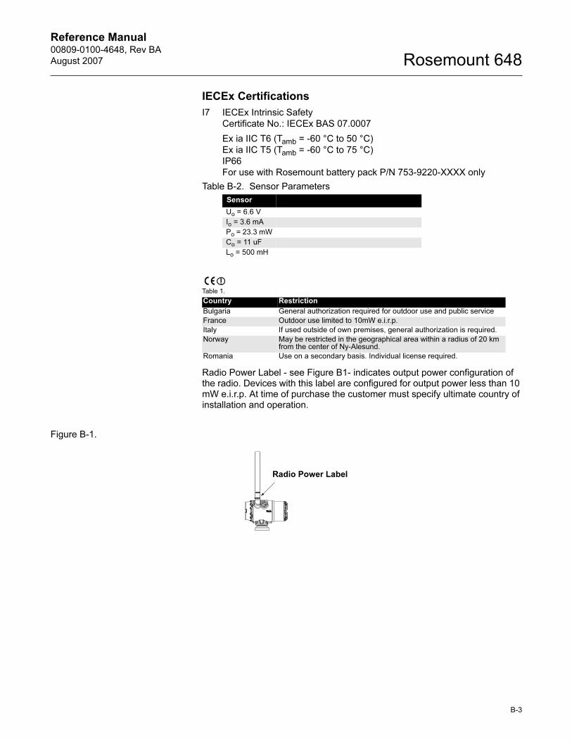
Reference Manual 00809-0100-4648, Rev BA
August 2007
B-3
Rosemount 648
IECEx Certifications
I7 IECEx Intrinsic Safety
Certificate No.: IECEx BAS 07.0007
Ex ia IIC T6 (Tamb = -60 °C to 50 °C)
Ex ia IIC T5 (Tamb = -60 °C to 75 °C)
IP66
For use with Rosemount battery pack P/N 753-9220-XXXX only
Radio Power Label - see Figure B1- indicates output power configuration of the radio. Devices with this label are configured for output power less than 10 mW e.i.r.p. At time of purchase the customer must specify ultimate country of installation and operation.
Figure B-1.
Table B-2. Sensor Parameters
Sensor
Uo = 6.6 V
Io = 3.6 mA
Po = 23.3 mW
Co = 11 uF
Lo = 500 mH
Table 1.
Country Restriction
Bulgaria General authorization required for outdoor use and public service
France Outdoor use limited to 10mW e.i.r.p.
Italy If used outside of own premises, general authorization is required.
Norway May be restricted in the geographical area within a radius of 20 km from the center of Ny-Alesund.
Romania Use on a secondary basis. Individual license required.
Radio Power Label
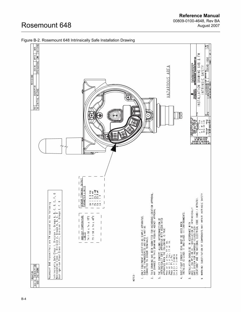
Reference Manual00809-0100-4648, Rev BA
August 2007Rosemount 648
B-4
Figure B-2. Rosemount 648 Intrinsically Safe Installation Drawing
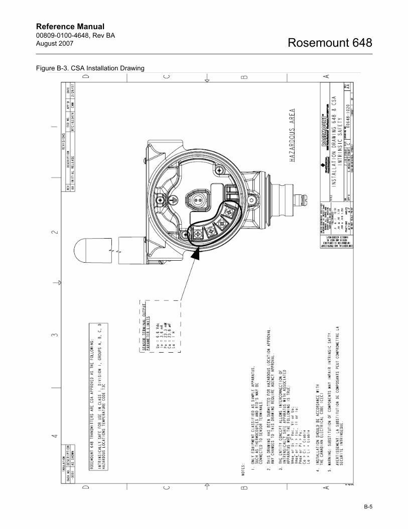
Reference Manual 00809-0100-4648, Rev BA
August 2007
B-5
Rosemount 648
Figure B-3. CSA Installation Drawing

Reference Manual00809-0100-4648, Rev BA
August 2007Rosemount 648
B-6


Emerson Process Management
© 2007 Rosemount Inc. All rights reserved.
¢00809-0100-4728g¤
The Emerson logo is a trade mark and service mark of Emerson Electric Co.Rosemount and the Rosemount logotype are registered trademarks of Rosemount Inc. PlantWeb is a registered trademark of one of the Emerson Process Management group of companies.HART is a registered trademark of the HART Communication Foundation.Lexan and Noryl are registered trademark of General Electric.All other marks are the property of their respective owners.
Reference Manual00809-0100-4648, Rev BA
August 2007
Emerson Process ManagementHeath PlaceBognor RegisWest Sussex PO22 9SHEnglandT 44 (1243) 863 121F 44 (1243) 867 554
Emerson Process Management Asia Pacific Private Limited1 Pandan CrescentSingapore 128461T (65) 6777 8211F (65) 6777 [email protected]
Rosemount Inc.8200 Market BoulevardChanhassen, MN 55317 USAT (U.S.) 1-800-999-9307T (International) (952) 906-8888F (952) 949-7001
www.rosemount.com