Embed Size (px)
Citation preview
Product Data Sheet00813-0100-4697, Rev GA
Catalog 2008 - 2009 Rosemount 848T Family
Rosemount 848T Multi-Input Temperature
Transmitter Family
• Provides installation and operational savingsfor temperature applications
• Inputs are independently configurable and
accept RTD, thermocouple, ohm, mV, and
4–20 mA
• Mounts anywhere - field hardened,
intrinsically safe, and low power
• Interfaces to any control architectures using
3420 or 1420 gateway devices
COMING SOON
Rosemount 848T Wireless
Temperature Transmitter
The Rosemount 848T Wireless is easy to use,
allowing leverage of existing practices, training, and
maintenance procedures without adding wiring costs.
Consult factory for availability.
www.ro
Contents
Overview: The First Choice in Temperature Monitoring. . . . . . . . . . . . . . . . . . page Temperature-2
The Rosemount 848T Eight Input Temperature Transmitter . . . . . . . . . . . . . . page Temperature-3
Specifications . . . . . . . . . . . . . . . . . . . . . . . . . . . . . . . . . . . . . . . . . . . . . . page Temperature-4
Product Certifications . . . . . . . . . . . . . . . . . . . . . . . . . . . . . . . . . . . . . . . . page Temperature-8
Dimensional Drawings . . . . . . . . . . . . . . . . . . . . . . . . . . . . . . . . . . . . . . .page Temperature-11
Ordering Information . . . . . . . . . . . . . . . . . . . . . . . . . . . . . . . . . . . . . . . . page Temperature-14
The Rosemount 848T Wireless Temperature Transmitter . . . . . . . . . . . . . . . page Temperature-16
Specifications . . . . . . . . . . . . . . . . . . . . . . . . . . . . . . . . . . . . . . . . . . . . . page Temperature-17
semount.com
Product Data Sheet00813-0100-4697, Rev GA
Catalog 2008 - 2009Rosemount 848T Family
Overview: The First Choice in Temperature MonitoringThe Rosemount 848T FOUNDATION
™ fieldbus Temperature Transmitter: Simplifies and reduces the cost of a plant’s
process control architecture. It eliminates traditional temperature monitoring methods (wire direct, low cost single
input transmitters, and multiplexers) with the introduction of this intrinsically safe, eight input transmitter that
mounts beside the process. The use of FOUNDATION™ fieldbus enables a quantum leap in temperature monitoring.
When combined with the Rosemount 3420 Fieldbus Interface Module, Rosemount 848T measurements can be
interfaced to existing systems.
The Rosemount 848T Wireless Temperature Transmitter: Ideal for high density measurement applications.
Reduces the total installed cost per wireless temperature measurement, which gives a cost effective solution in
hard-to-reach or cost prohibitive locations. The Rosemount 848T Wireless is an Intrinsically Safe (I.S.) device that
can be mounted practically anywhere. Each input can be configured for a variety of sensors, such as RTD,
thermocouple, mV, ohm, and 4–20 mA signals.
HIGH DENSITY MEASUREMENT APPLICATIONSIdeal for situations with multiple temperature
measurements within close proximity to each other,
such as distillation columns, tanks, boilers, and heat
exchangers.
ECONOMICAL SOLUTIONReduces installation and operational costs by as
much as 70 percent per point when compared to
traditional sensor wire direct application temperature
measurements.
MOUNTS PRACTICALLY ANYWHEREProvides optimum mounting flexibility with its
ambient temperature limits, RFI immunity
compliance, Intrinsic Safety approvals, and ability to
mount in industrial environments.
Rosemount High Density Temperature Solutions
Rosemount 1080/1082 Multipoint SensorsProvides multiple measurement points in one process connection
using thermocouple and RTD sensors. Integrate with 848T Multi
Input Temperature Transmitters for a complete solution.
3420 Fieldbus Interface ModuleProvides an interface between FOUNDATION fieldbus instruments
and systems without fieldbus capability using standard interface
protocols.
1420 Wireless GatewayOffers robust security, easy host integration with no additional
software, and continuous network optimization to maximize data
reliability and power module life of the wireless devices. Provides
interface between WirelessHART field network and host systems
using standard interface protocols.
Temperature-2
Product Data Sheet00813-0100-4697, Rev GA
Catalog 2008 - 2009 Rosemount 848T Family
The Rosemount 848T Eight Input Temperature Transmitter
ECONOMICAL SOLUTIONThe Rosemount 848T offers the lowest cost solution
for temperature monitoring measurements (e.g.
distillation columns, tanks, reactors, boilers, etc.). It
can reduce installed costs by as much as 70 percent
per point when compared to traditional sensor wire
direct applications.
REDUCES I.S. BARRIER COSTSFor I.S. installations, only one barrier is needed to
safely power several Rosemount 848T transmitters.
As a result, one barrier can support at least 24
temperature measurement points, which results in
significant savings. The new Fieldbus Intrinsically
Safe Concept (FISCO) certification on the
Rosemount 848T allows even more measurements
per I.S. segment.
EIGHT INDEPENDENT SENSOR INPUTSThe Rosemount 848T accepts eight independently
configurable sensor inputs (2- and 3-wire RTDs,
thermocouples, mV, and ohm).
MOUNTS PRACTICALLY ANYWHEREThe Rosemount 848T’s ambient temperature limits,
RFI immunity compliance, I.S. approvals, and ability
to mount in industrial environments provides
optimum mounting flexibility.
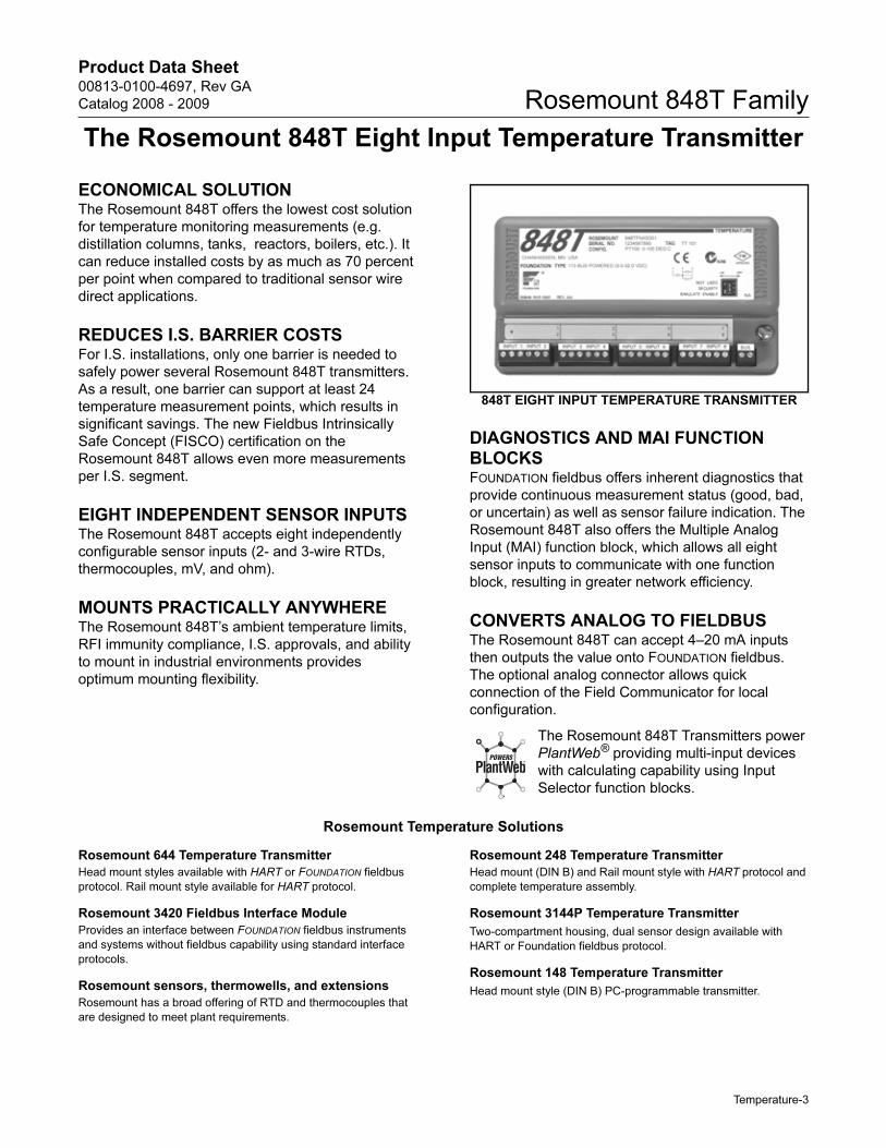
848T EIGHT INPUT TEMPERATURE TRANSMITTER
DIAGNOSTICS AND MAI FUNCTION BLOCKSFOUNDATION fieldbus offers inherent diagnostics that
provide continuous measurement status (good, bad,
or uncertain) as well as sensor failure indication. The
Rosemount 848T also offers the Multiple Analog
Input (MAI) function block, which allows all eight
sensor inputs to communicate with one function
block, resulting in greater network efficiency.
CONVERTS ANALOG TO FIELDBUSThe Rosemount 848T can accept 4–20 mA inputs
then outputs the value onto FOUNDATION fieldbus.
The optional analog connector allows quick
connection of the Field Communicator for local
configuration.
The Rosemount 848T Transmitters power
PlantWeb® providing multi-input devices
with calculating capability using Input
Selector function blocks.
Rosemount Temperature Solutions
Rosemount 644 Temperature Transmitter
Head mount styles available with HART or FOUNDATION fieldbus
protocol. Rail mount style available for HART protocol.
Rosemount 3420 Fieldbus Interface Module
Provides an interface between FOUNDATION fieldbus instruments
and systems without fieldbus capability using standard interface
protocols.
Rosemount sensors, thermowells, and extensions
Rosemount has a broad offering of RTD and thermocouples that
are designed to meet plant requirements.
Rosemount 248 Temperature Transmitter
Head mount (DIN B) and Rail mount style with HART protocol and
complete temperature assembly.
Rosemount 3144P Temperature Transmitter
Two-compartment housing, dual sensor design available with
HART or Foundation fieldbus protocol.
Rosemount 148 Temperature Transmitter
Head mount style (DIN B) PC-programmable transmitter.
Temperature-3
Product Data Sheet00813-0100-4697, Rev GA
Catalog 2008 - 2009Rosemount 848T Family
Specifications
FUNCTIONAL
Inputs
Eight independently configurable channels including combinations
of 2- and 3-wire RTDs, thermocouples, mV, and Ω inputs.
4-20 mA inputs using optional connector(s).
All sensor terminals are rated to 42.4 VDC.
Outputs
Manchester-encoded digital signal that conforms to IEC 1158-2
and ISA 50.02.
Status
If self-diagnostics detect a sensor burnout or a transmitter failure,
the status of the measurement will be updated accordingly.
Ambient Temperature Limits
–40 to 185 °F (–40 to 85 °C)
Isolation
Input/output isolation is tested to 500 VAC rms (707 VDC).
Input/input isolation between each sensor input connector is
tested to 500 VAC rms (707 VDC). Input/input isolation between
sensors on the same input connector is 3 VAC at 50 – 60 Hz, 1.5
VDC.
Power Supply
Powered over FOUNDATION fieldbus with standard fieldbus power
supplies. The transmitter operates between 9.0 and 32.0 V dc,
22 mA maximum. (Transmitter power terminals are rated
to 42.4 V dc.)
Transient Protection
The transient protector (option code T1) helps to prevent damage
to the transmitter from transients induced on the loop wiring by
lightening, welding, heavy electrical equipment, or switch gears.
This option is installed at the factory for the Rosemount 848T and
is not intended for field installation.
ASME B 16.5 (ANSI)/IEEE C62.41-1991
(IEEE 587), Location Categories A2, B3.
6 kV / 3 kA peak (1.2 x 50 μS Wave 8 x 20 μS Combination Wave)
6 kV / 0.5 kA peak (100 kHz Ring Wave)
4 kV peak EFT (5 x 50 nS Electrical Fast Transient)
Update Time
Approximately 1.5 seconds to read all eight inputs.
Humidity Limits
0–100% non-condensing relative humidity
Turn-on Time
Performance within specifications is achieved in less than 50
seconds after power is applied to the transmitter.
Alarms
The AI and ISEL function blocks allow the user to configure the
alarms to HI-HI, HI, LO, or LO-LO with a variety of priority levels
and hysteresis settings.
Backup Link Active Scheduler (LAS)
The transmitter is classified as a device link master, which means
it can function as a Link Active Scheduler (LAS) if the current link
master device fails or is removed from the segment.
The host or other configuration tool is used to download the
schedule for the application to the link master device. In the
absence of a primary link master, the transmitter will claim the LAS
and provide permanent control for the H1 segment.
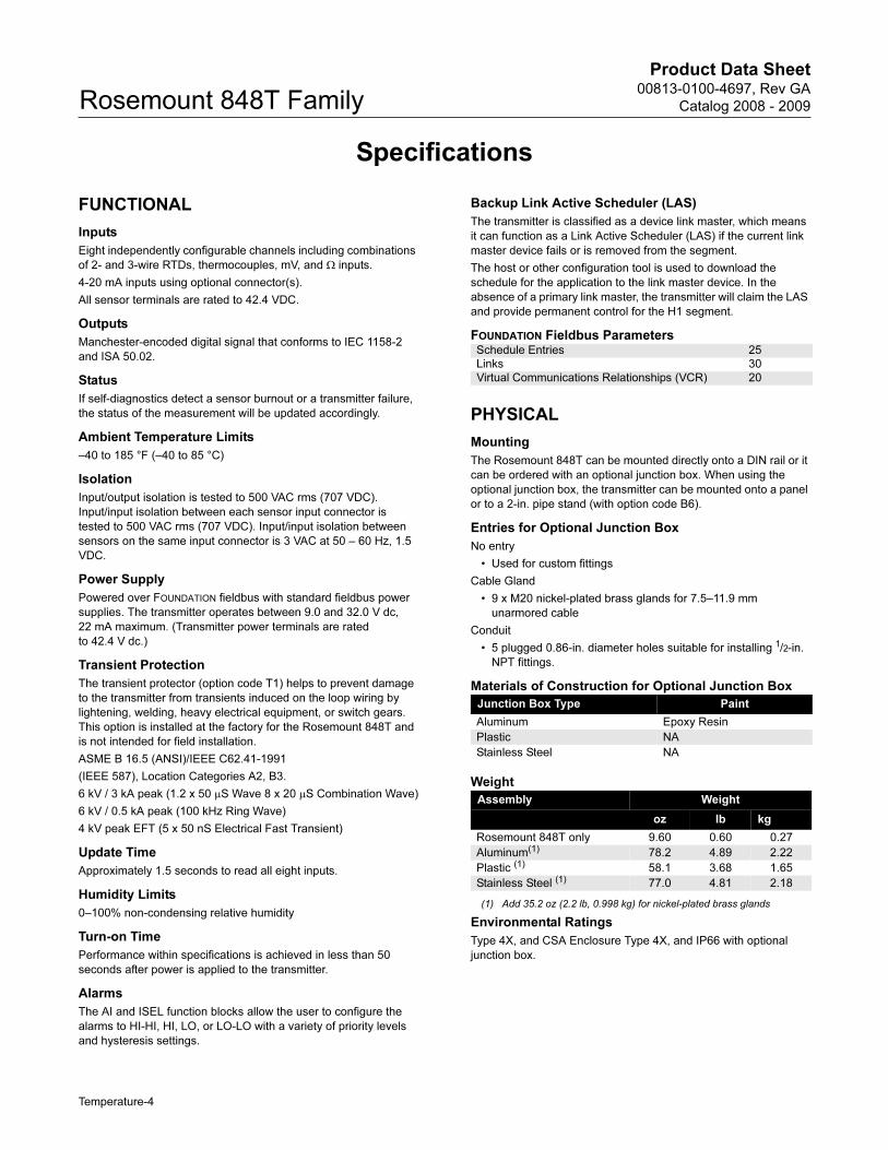
FOUNDATION Fieldbus Parameters
PHYSICAL
Mounting
The Rosemount 848T can be mounted directly onto a DIN rail or it
can be ordered with an optional junction box. When using the
optional junction box, the transmitter can be mounted onto a panel
or to a 2-in. pipe stand (with option code B6).
Entries for Optional Junction Box
No entry
• Used for custom fittings
Cable Gland
• 9 x M20 nickel-plated brass glands for 7.5–11.9 mm
unarmored cable
Conduit
• 5 plugged 0.86-in. diameter holes suitable for installing 1/2-in.
NPT fittings.
Materials of Construction for Optional Junction Box
Weight
Environmental Ratings
Type 4X, and CSA Enclosure Type 4X, and IP66 with optional
junction box.
Schedule Entries 25
Links 30
Virtual Communications Relationships (VCR) 20
Junction Box Type Paint
Aluminum Epoxy Resin
Plastic NA
Stainless Steel NA
Assembly Weight
oz lb kg
Rosemount 848T only 9.60 0.60 0.27
Aluminum(1)
(1) Add 35.2 oz (2.2 lb, 0.998 kg) for nickel-plated brass glands
78.2 4.89 2.22
Plastic (1) 58.1 3.68 1.65
Stainless Steel (1) 77.0 4.81 2.18
Temperature-4
Product Data Sheet00813-0100-4697, Rev GA
Catalog 2008 - 2009 Rosemount 848T Family
FUNCTION BLOCKSAnalog Input (AI)
• Processes the measurement and makes it available on the
fieldbus segment.
• Allows filtering, alarming, and engineering unit changes.
Input Selector (ISEL)
• Used to select between inputs and generate an output using
specific selection strategies such as minimum, maximum,
midpoint, or average temperature.
• Since the temperature value always contains the
measurement status, this block allows the selection to be
restricted to the first “good” measurement.
Multiple Analog Input Block (MAI)
• The MAI block allows the eight AI blocks to be multiplexed
together so they serve as one function block on the H1
segment, resulting in greater network efficiency.
PERFORMANCE The transmitter maintains a specification conformance of
at least ±3�.
Stability
• ±0.1% of reading or 0.1 °C (0.18 °F), whichever is greater, for
2 years for RTDs.
• ±0.1% of reading or 0.1 °C (0.18 °F), whichever is greater, for
1 year for thermocouples.
Self Calibration
The transmitter’s analog-to-digital circuitry automatically
self-calibrates for each temperature update by comparing the
dynamic measurement to extremely stable and accurate internal
reference elements.
Vibration Effect
Transmitters are tested to the following vibration conditions with no
effect on performance:
CE Electromagnetic Compatibility Compliance Testing
Meets the criteria under IEC 61326 Amendment 1, 2002:
Frequency Acceleration
10 - 60 Hz 0.21 mm peak displacement
60 - 2000 Hz 3 g
Emissions
• 30–230 MHz, 30 dB (uV/m) at 10 m
• 230–1000 MHz, 37 dB (uV/m) at 10 m
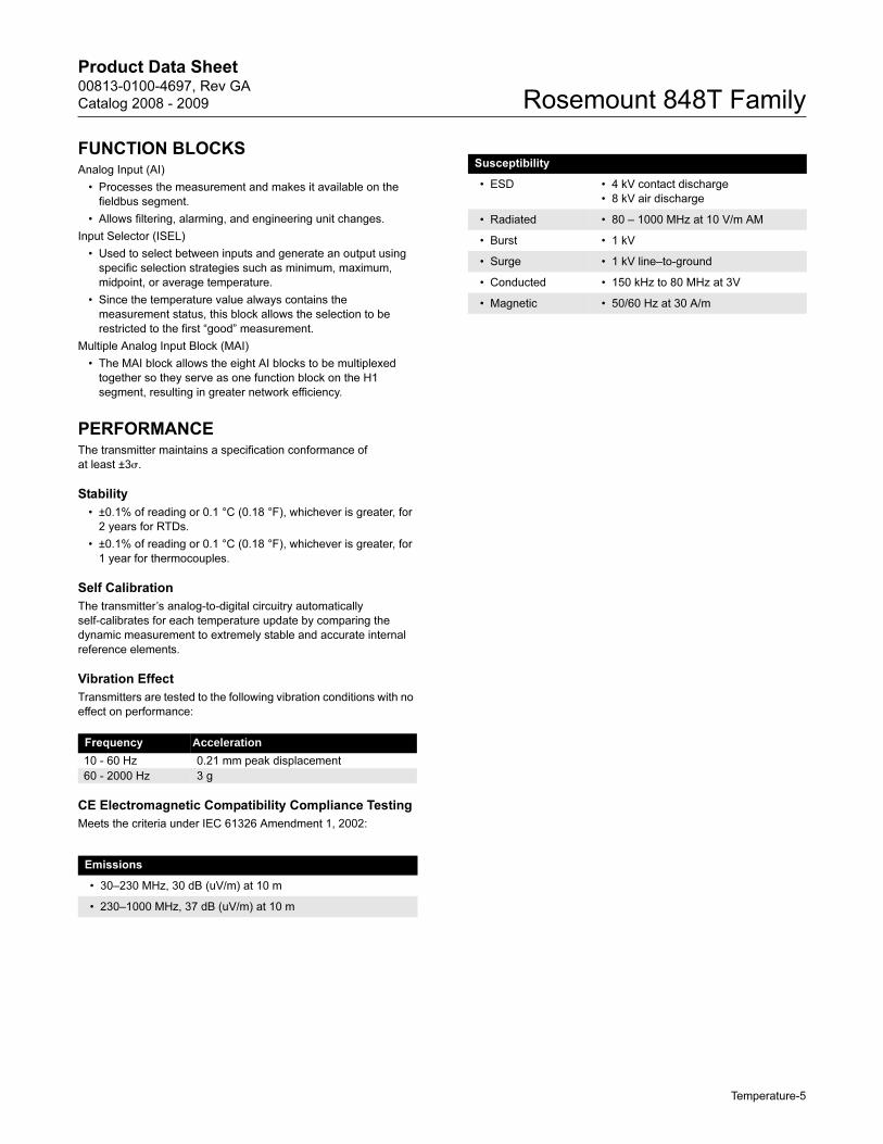
Susceptibility
• ESD • 4 kV contact discharge
• 8 kV air discharge
• Radiated • 80 – 1000 MHz at 10 V/m AM
• Burst • 1 kV
• Surge • 1 kV line–to-ground
• Conducted • 150 kHz to 80 MHz at 3V
• Magnetic • 50/60 Hz at 30 A/m
Temperature-5
Product Data Sheet00813-0100-4697, Rev GA
Catalog 2008 - 2009Rosemount 848T Family
ACCURACY
Accuracy Notes
Differential capability exists between any two sensor types:
For all differential configurations, the input range is X to +Y where
Accuracy for differential configurations:
If sensor types are similar (for example, both RTDs or both
thermocouples), the accuracy = 1.5 times worst case accuracy of
either sensor type. If sensor types are dissimilar (for example, one
RTD and one thermocouple), the accuracy = Sensor 1 Accuracy +
Sensor 2 Accuracy.
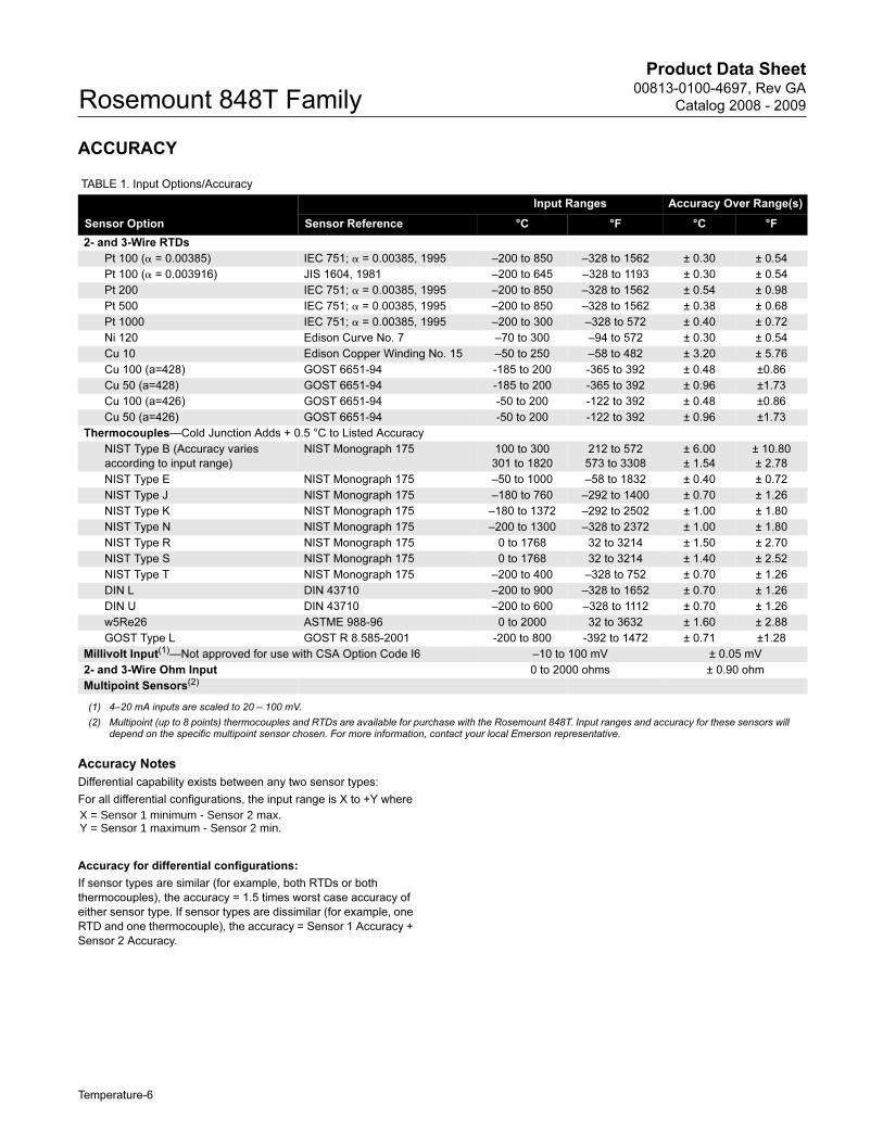
TABLE 1. Input Options/Accuracy
Sensor Option
Input Ranges Accuracy Over Range(s)
Sensor Reference °C °F °C °F
2- and 3-Wire RTDs
Pt 100 (� = 0.00385) IEC 751; � = 0.00385, 1995 –200 to 850 –328 to 1562 ± 0.30 ± 0.54
Pt 100 (� = 0.003916) JIS 1604, 1981 –200 to 645 –328 to 1193 ± 0.30 ± 0.54
Pt 200 IEC 751; � = 0.00385, 1995 –200 to 850 –328 to 1562 ± 0.54 ± 0.98
Pt 500 IEC 751; � = 0.00385, 1995 –200 to 850 –328 to 1562 ± 0.38 ± 0.68
Pt 1000 IEC 751; � = 0.00385, 1995 –200 to 300 –328 to 572 ± 0.40 ± 0.72
Ni 120 Edison Curve No. 7 –70 to 300 –94 to 572 ± 0.30 ± 0.54
Cu 10 Edison Copper Winding No. 15 –50 to 250 –58 to 482 ± 3.20 ± 5.76
Cu 100 (a=428) GOST 6651-94 -185 to 200 -365 to 392 ± 0.48 ±0.86
Cu 50 (a=428) GOST 6651-94 -185 to 200 -365 to 392 ± 0.96 ±1.73
Cu 100 (a=426) GOST 6651-94 -50 to 200 -122 to 392 ± 0.48 ±0.86
Cu 50 (a=426) GOST 6651-94 -50 to 200 -122 to 392 ± 0.96 ±1.73
Thermocouples—Cold Junction Adds + 0.5 °C to Listed Accuracy
NIST Type B (Accuracy varies
according to input range)
NIST Monograph 175 100 to 300
301 to 1820
212 to 572
573 to 3308
± 6.00
± 1.54
± 10.80
± 2.78
NIST Type E NIST Monograph 175 –50 to 1000 –58 to 1832 ± 0.40 ± 0.72
NIST Type J NIST Monograph 175 –180 to 760 –292 to 1400 ± 0.70 ± 1.26
NIST Type K NIST Monograph 175 –180 to 1372 –292 to 2502 ± 1.00 ± 1.80
NIST Type N NIST Monograph 175 –200 to 1300 –328 to 2372 ± 1.00 ± 1.80
NIST Type R NIST Monograph 175 0 to 1768 32 to 3214 ± 1.50 ± 2.70
NIST Type S NIST Monograph 175 0 to 1768 32 to 3214 ± 1.40 ± 2.52
NIST Type T NIST Monograph 175 –200 to 400 –328 to 752 ± 0.70 ± 1.26
DIN L DIN 43710 –200 to 900 –328 to 1652 ± 0.70 ± 1.26
DIN U DIN 43710 –200 to 600 –328 to 1112 ± 0.70 ± 1.26
w5Re26 ASTME 988-96 0 to 2000 32 to 3632 ± 1.60 ± 2.88
GOST Type L GOST R 8.585-2001 -200 to 800 -392 to 1472 ± 0.71 ±1.28
Millivolt Input(1)—Not approved for use with CSA Option Code I6 –10 to 100 mV ± 0.05 mV
2- and 3-Wire Ohm Input 0 to 2000 ohms ± 0.90 ohm
Multipoint Sensors(2)
(1) 4–20 mA inputs are scaled to 20 – 100 mV.
(2) Multipoint (up to 8 points) thermocouples and RTDs are available for purchase with the Rosemount 848T. Input ranges and accuracy for these sensors will depend on the specific multipoint sensor chosen. For more information, contact your local Emerson representative.
X = Sensor 1 minimum - Sensor 2 max.Y = Sensor 1 maximum - Sensor 2 min.
Temperature-6
Product Data Sheet00813-0100-4697, Rev GA
Catalog 2008 - 2009 Rosemount 848T Family
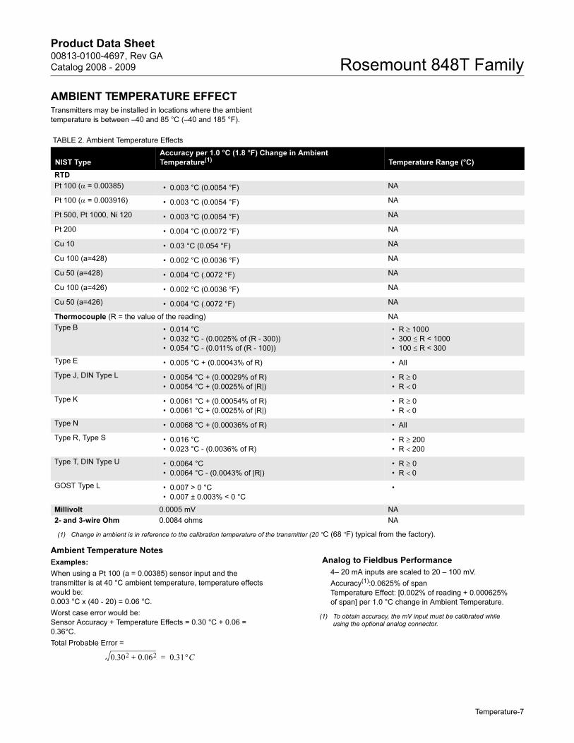
AMBIENT TEMPERATURE EFFECTTransmitters may be installed in locations where the ambient
temperature is between –40 and 85 °C (–40 and 185 °F).
Ambient Temperature Notes
Examples:
When using a Pt 100 (a = 0.00385) sensor input and the
transmitter is at 40 °C ambient temperature, temperature effects
would be:
0.003 °C x (40 - 20) = 0.06 °C.
Worst case error would be:
Sensor Accuracy + Temperature Effects = 0.30 °C + 0.06 =
0.36°C.
Total Probable Error =
TABLE 2. Ambient Temperature Effects
NIST Type
Accuracy per 1.0 °C (1.8 °F) Change in Ambient
Temperature(1)C Temperature Range (°C)
RTD
Pt 100 (α = 0.00385) • 0.003 °C (0.0054 °F) NA
Pt 100 (α = 0.003916) • 0.003 °C (0.0054 °F) NA
Pt 500, Pt 1000, Ni 120 • 0.003 °C (0.0054 °F) NA
Pt 200 • 0.004 °C (0.0072 °F) NA
Cu 10 • 0.03 °C (0.054 °F) NA
Cu 100 (a=428) • 0.002 °C (0.0036 °F) NA
Cu 50 (a=428) • 0.004 °C (.0072 °F) NA
Cu 100 (a=426) • 0.002 °C (0.0036 °F) NA
Cu 50 (a=426) • 0.004 °C (.0072 °F) NA
Thermocouple (R = the value of the reading) NA
Type B • 0.014 °C
• 0.032 °C - (0.0025% of (R - 300))
• 0.054 °C - (0.011% of (R - 100))
• R ≥ 1000
• 300 ≤ R < 1000
• 100 ≤ R < 300
Type E • 0.005 °C + (0.00043% of R) • All
Type J, DIN Type L • 0.0054 °C + (0.00029% of R)
• 0.0054 °C + (0.0025% of |R|)
• R ≥ 0
• R < 0
Type K • 0.0061 °C + (0.00054% of R)
• 0.0061 °C + (0.0025% of |R|)
• R ≥ 0
• R < 0
Type N • 0.0068 °C + (0.00036% of R) • All
Type R, Type S • 0.016 °C
• 0.023 °C - (0.0036% of R)
• R ≥ 200
• R < 200
Type T, DIN Type U • 0.0064 °C
• 0.0064 °C - (0.0043% of |R|)
• R ≥ 0
• R < 0
GOST Type L • 0.007 > 0 °C
• 0.007 ± 0.003% < 0 °C
•
Millivolt 0.0005 mV NA
2- and 3-wire Ohm 0.0084 ohms NA
(1) Change in ambient is in reference to the calibration temperature of the transmitter (20 °C (68 °F) typical from the factory).
0.302 0.062+ 0.31°C=
Analog to Fieldbus Performance
4– 20 mA inputs are scaled to 20 – 100 mV.
Accuracy(1):0.0625% of span
Temperature Effect: [0.002% of reading + 0.000625%
of span] per 1.0 °C change in Ambient Temperature.
(1) To obtain accuracy, the mV input must be calibrated while using the optional analog connector.
Temperature-7
Product Data Sheet00813-0100-4697, Rev GA
Catalog 2008 - 2009Rosemount 848T Family
Product Certifications
HAZARDOUS LOCATIONS CERTIFICATION
North American Certificates
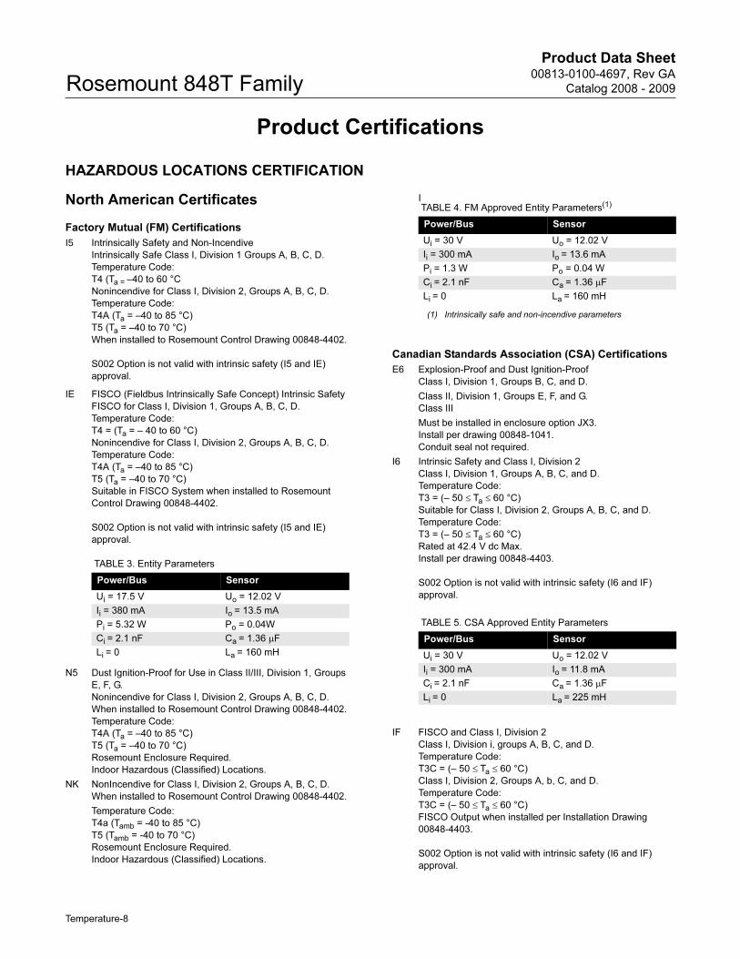
Factory Mutual (FM) Certifications
I5 Intrinsically Safety and Non-Incendive
Intrinsically Safe Class I, Division 1 Groups A, B, C, D.
Temperature Code:
T4 (Ta = –40 to 60 °C
Nonincendive for Class I, Division 2, Groups A, B, C, D.
Temperature Code:
T4A (Ta = –40 to 85 °C)
T5 (Ta = –40 to 70 °C)
When installed to Rosemount Control Drawing 00848-4402.
S002 Option is not valid with intrinsic safety (I5 and IE)
approval.
IE FISCO (Fieldbus Intrinsically Safe Concept) Intrinsic Safety
FISCO for Class I, Division 1, Groups A, B, C, D.
Temperature Code:
T4 = (Ta = – 40 to 60 °C)
Nonincendive for Class I, Division 2, Groups A, B, C, D.
Temperature Code:
T4A (Ta = –40 to 85 °C)
T5 (Ta = –40 to 70 °C)
Suitable in FISCO System when installed to Rosemount
Control Drawing 00848-4402.
S002 Option is not valid with intrinsic safety (I5 and IE)
approval.
N5 Dust Ignition-Proof for Use in Class II/III, Division 1, Groups
E, F, G.
Nonincendive for Class I, Division 2, Groups A, B, C, D.
When installed to Rosemount Control Drawing 00848-4402.
Temperature Code:
T4A (Ta = –40 to 85 °C)
T5 (Ta = –40 to 70 °C)
Rosemount Enclosure Required.
Indoor Hazardous (Classified) Locations.
NK NonIncendive for Class I, Division 2, Groups A, B, C, D.
When installed to Rosemount Control Drawing 00848-4402.
Temperature Code:
T4a (Tamb = -40 to 85 °C)
T5 (Tamb = -40 to 70 °C)
Rosemount Enclosure Required.
Indoor Hazardous (Classified) Locations.
I
Canadian Standards Association (CSA) Certifications
E6 Explosion-Proof and Dust Ignition-Proof
Class I, Division 1, Groups B, C, and D.
Class II, Division 1, Groups E, F, and G.
Class III
Must be installed in enclosure option JX3.
Install per drawing 00848-1041.
Conduit seal not required.
I6 Intrinsic Safety and Class I, Division 2
Class I, Division 1, Groups A, B, C, and D.
Temperature Code:
T3 = (– 50 ≤ Ta ≤ 60 °C)
Suitable for Class I, Division 2, Groups A, B, C, and D.
Temperature Code:
T3 = (– 50 ≤ Ta ≤ 60 °C)
Rated at 42.4 V dc Max.
Install per drawing 00848-4403.
S002 Option is not valid with intrinsic safety (I6 and IF)
approval.
IF FISCO and Class I, Division 2
Class I, Division i, groups A, B, C, and D.
Temperature Code:
T3C = (– 50 ≤ Ta ≤ 60 °C)
Class I, Division 2, Groups A, b, C, and D.
Temperature Code:
T3C = (– 50 ≤ Ta ≤ 60 °C)
FISCO Output when installed per Installation Drawing
00848-4403.
S002 Option is not valid with intrinsic safety (I6 and IF)
approval.
TABLE 3. Entity Parameters
Power/Bus Sensor
Ui = 17.5 V Uo = 12.02 V
Ii = 380 mA Io = 13.5 mA
Pi = 5.32 W Po = 0.04W
Ci = 2.1 nF Ca = 1.36 μF
Li = 0 La = 160 mH
TABLE 4. FM Approved Entity Parameters(1)
(1) Intrinsically safe and non-incendive parameters
Power/Bus Sensor
Ui = 30 V Uo = 12.02 V
Ii = 300 mA Io = 13.6 mA
Pi = 1.3 W Po = 0.04 W
Ci = 2.1 nF Ca = 1.36 μF
Li = 0 La = 160 mH
TABLE 5. CSA Approved Entity Parameters
Power/Bus Sensor
Ui = 30 V Uo = 12.02 V
Ii = 300 mA Io = 11.8 mA
Ci = 2.1 nF Ca = 1.36 μF
Li = 0 La = 225 mH
Temperature-8
Product Data Sheet00813-0100-4697, Rev GA
Catalog 2008 - 2009 Rosemount 848T Family
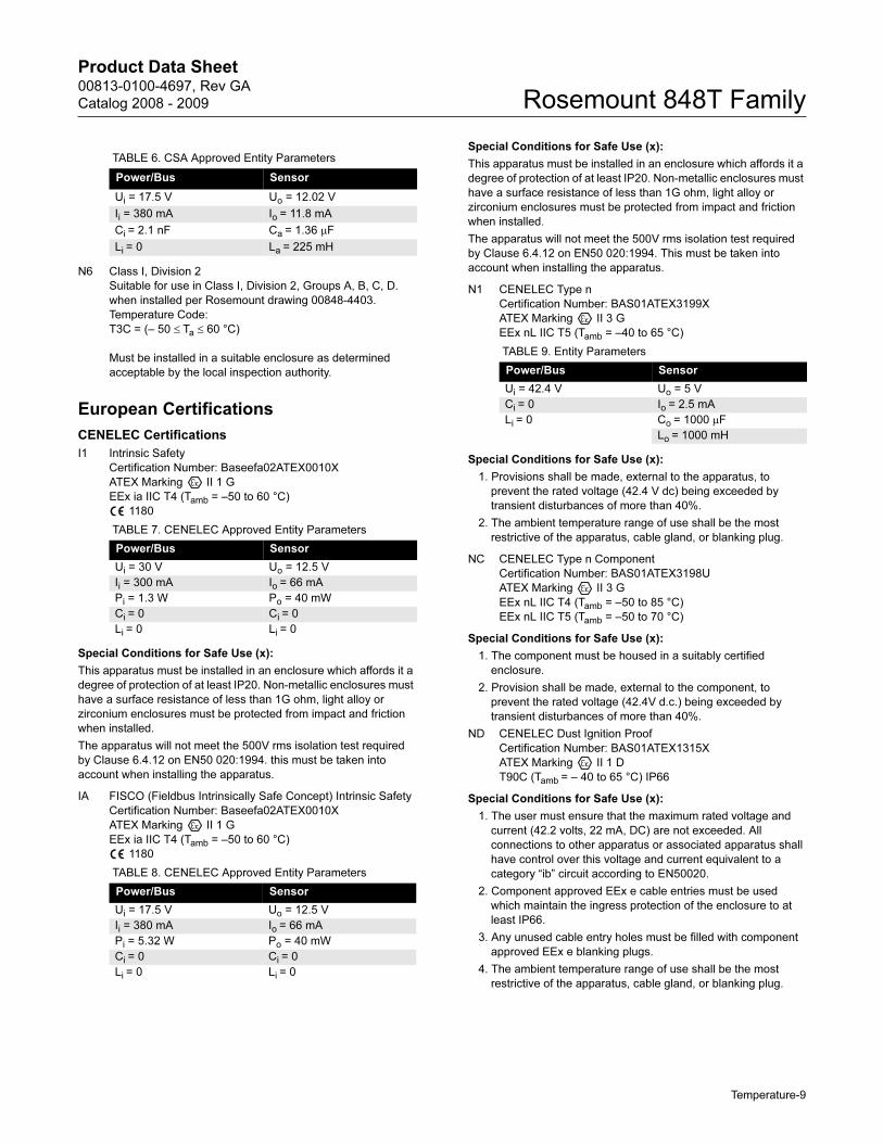
N6 Class I, Division 2
Suitable for use in Class I, Division 2, Groups A, B, C, D.
when installed per Rosemount drawing 00848-4403.
Temperature Code:
T3C = (– 50 ≤ Ta ≤ 60 °C)
Must be installed in a suitable enclosure as determined
acceptable by the local inspection authority.
European Certifications
CENELEC Certifications
I1 Intrinsic Safety
Certification Number: Baseefa02ATEX0010X
ATEX Marking II 1 G
EEx ia IIC T4 (Tamb = –50 to 60 °C)
1180
Special Conditions for Safe Use (x):
This apparatus must be installed in an enclosure which affords it a
degree of protection of at least IP20. Non-metallic enclosures must
have a surface resistance of less than 1G ohm, light alloy or
zirconium enclosures must be protected from impact and friction
when installed.
The apparatus will not meet the 500V rms isolation test required
by Clause 6.4.12 on EN50 020:1994. this must be taken into
account when installing the apparatus.
IA FISCO (Fieldbus Intrinsically Safe Concept) Intrinsic Safety
Certification Number: Baseefa02ATEX0010X
ATEX Marking II 1 G
EEx ia IIC T4 (Tamb = –50 to 60 °C)
1180
Special Conditions for Safe Use (x):
This apparatus must be installed in an enclosure which affords it a
degree of protection of at least IP20. Non-metallic enclosures must
have a surface resistance of less than 1G ohm, light alloy or
zirconium enclosures must be protected from impact and friction
when installed.
The apparatus will not meet the 500V rms isolation test required
by Clause 6.4.12 on EN50 020:1994. This must be taken into
account when installing the apparatus.
N1 CENELEC Type n
Certification Number: BAS01ATEX3199X
ATEX Marking II 3 G
EEx nL IIC T5 (Tamb = –40 to 65 °C)
Special Conditions for Safe Use (x):
1. Provisions shall be made, external to the apparatus, to
prevent the rated voltage (42.4 V dc) being exceeded by
transient disturbances of more than 40%.
2. The ambient temperature range of use shall be the most
restrictive of the apparatus, cable gland, or blanking plug.
NC CENELEC Type n Component
Certification Number: BAS01ATEX3198U
ATEX Marking II 3 G
EEx nL IIC T4 (Tamb = –50 to 85 °C)
EEx nL IIC T5 (Tamb = –50 to 70 °C)
Special Conditions for Safe Use (x):
1. The component must be housed in a suitably certified
enclosure.
2. Provision shall be made, external to the component, to
prevent the rated voltage (42.4V d.c.) being exceeded by
transient disturbances of more than 40%.
ND CENELEC Dust Ignition Proof
Certification Number: BAS01ATEX1315X
ATEX Marking II 1 D
T90C (Tamb = – 40 to 65 °C) IP66
Special Conditions for Safe Use (x):
1. The user must ensure that the maximum rated voltage and
current (42.2 volts, 22 mA, DC) are not exceeded. All
connections to other apparatus or associated apparatus shall
have control over this voltage and current equivalent to a
category “ib” circuit according to EN50020.
2. Component approved EEx e cable entries must be used
which maintain the ingress protection of the enclosure to at
least IP66.
3. Any unused cable entry holes must be filled with component
approved EEx e blanking plugs.
4. The ambient temperature range of use shall be the most
restrictive of the apparatus, cable gland, or blanking plug.
TABLE 6. CSA Approved Entity Parameters
Power/Bus Sensor
Ui = 17.5 V Uo = 12.02 V
Ii = 380 mA Io = 11.8 mA
Ci = 2.1 nF Ca = 1.36 μF
Li = 0 La = 225 mH
TABLE 7. CENELEC Approved Entity Parameters
Power/Bus Sensor
Ui = 30 V Uo = 12.5 V
Ii = 300 mA Io = 66 mA
Pi = 1.3 W Po = 40 mW
Ci = 0 Ci = 0
Li = 0 Li = 0
TABLE 8. CENELEC Approved Entity Parameters
Power/Bus Sensor
Ui = 17.5 V Uo = 12.5 V
Ii = 380 mA Io = 66 mA
Pi = 5.32 W Po = 40 mW
Ci = 0 Ci = 0
Li = 0 Li = 0
TABLE 9. Entity Parameters
Power/Bus Sensor
Ui = 42.4 V Uo = 5 V
Ci = 0 Io = 2.5 mA
Li = 0 Co = 1000 μF
Lo = 1000 mH
Temperature-9
Product Data Sheet00813-0100-4697, Rev GA
Catalog 2008 - 2009Rosemount 848T Family
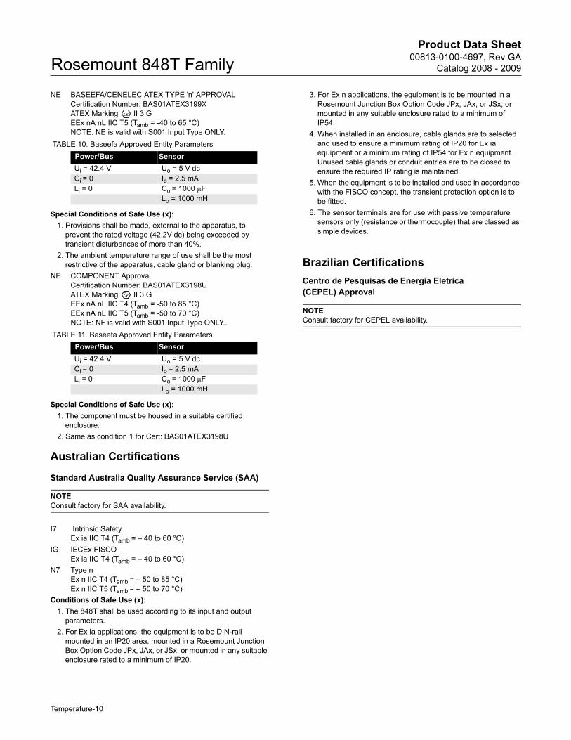
NE BASEEFA/CENELEC ATEX TYPE 'n' APPROVAL
Certification Number: BAS01ATEX3199X
ATEX Marking II 3 G
EEx nA nL IIC T5 (Tamb = -40 to 65 °C)
NOTE: NE is valid with S001 Input Type ONLY.
Special Conditions of Safe Use (x):
1. Provisions shall be made, external to the apparatus, to
prevent the rated voltage (42.2V dc) being exceeded by
transient disturbances of more than 40%.
2. The ambient temperature range of use shall be the most
restrictive of the apparatus, cable gland or blanking plug.
NF COMPONENT Approval
Certification Number: BAS01ATEX3198U
ATEX Marking II 3 G
EEx nA nL IIC T4 (Tamb = -50 to 85 °C)
EEx nA nL IIC T5 (Tamb = -50 to 70 °C)
NOTE: NF is valid with S001 Input Type ONLY..
Special Conditions of Safe Use (x):
1. The component must be housed in a suitable certified
enclosure.
2. Same as condition 1 for Cert: BAS01ATEX3198U
Australian Certifications
Standard Australia Quality Assurance Service (SAA)
NOTE
Consult factory for SAA availability.
I7 Intrinsic Safety
Ex ia IIC T4 (Tamb = – 40 to 60 °C)
IG IECEx FISCO
Ex ia IIC T4 (Tamb = – 40 to 60 °C)
N7 Type n
Ex n IIC T4 (Tamb = – 50 to 85 °C)
Ex n IIC T5 (Tamb = – 50 to 70 °C)
Conditions of Safe Use (x):
1. The 848T shall be used according to its input and output
parameters.
2. For Ex ia applications, the equipment is to be DIN-rail
mounted in an IP20 area, mounted in a Rosemount Junction
Box Option Code JPx, JAx, or JSx, or mounted in any suitable
enclosure rated to a minimum of IP20.
3. For Ex n applications, the equipment is to be mounted in a
Rosemount Junction Box Option Code JPx, JAx, or JSx, or
mounted in any suitable enclosure rated to a minimum of
IP54.
4. When installed in an enclosure, cable glands are to selected
and used to ensure a minimum rating of IP20 for Ex ia
equipment or a minimum rating of IP54 for Ex n equipment.
Unused cable glands or conduit entries are to be closed to
ensure the required IP rating is maintained.
5. When the equipment is to be installed and used in accordance
with the FISCO concept, the transient protection option is to
be fitted.
6. The sensor terminals are for use with passive temperature
sensors only (resistance or thermocouple) that are classed as
simple devices.
Brazilian Certifications
Centro de Pesquisas de Energia Eletrica
(CEPEL) Approval
NOTE
Consult factory for CEPEL availability.
TABLE 10. Baseefa Approved Entity Parameters
Power/Bus Sensor
Ui = 42.4 V Uo = 5 V dc
Ci = 0 Io = 2.5 mA
Li = 0 Co = 1000 μF
Lo = 1000 mH
TABLE 11. Baseefa Approved Entity Parameters
Power/Bus Sensor
Ui = 42.4 V Uo = 5 V dc
Ci = 0 Io = 2.5 mA
Li = 0 Co = 1000 μF
Lo = 1000 mH
Temperature-10
Product Data Sheet00813-0100-4697, Rev GA
Catalog 2008 - 2009 Rosemount 848T Family
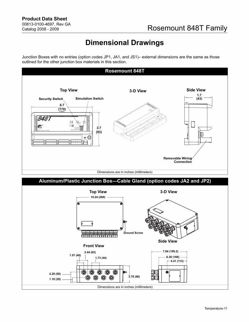
Dimensional Drawings
Junction Boxes with no entries (option codes JP1, JA1, and JS1)– external dimensions are the same as those
outlined for the other junction box materials in this section.
Rosemount 848T
Dimensions are in inches (millimeters)
Aluminum/Plastic Junction Box—Cable Gland (option codes JA2 and JP2)
Dimensions are in inches (millimeters)
Top View 3-D View Side View
Security Switch Simulation Switch1.7(43)
Removable WiringConnection
6.7
(170)
3.7
(93)
Top View 3-D View
Front ViewSide View
4.41 (112)
10.24 (260)
1.73 (44)
2.44 (62)
2.28 (58)
1.10 (28)
7.84 (199.2)
6.30 (160)
3.78 (96)
1.57 (40)
Ground Screw
Temperature-11
Product Data Sheet00813-0100-4697, Rev GA
Catalog 2008 - 2009Rosemount 848T Family
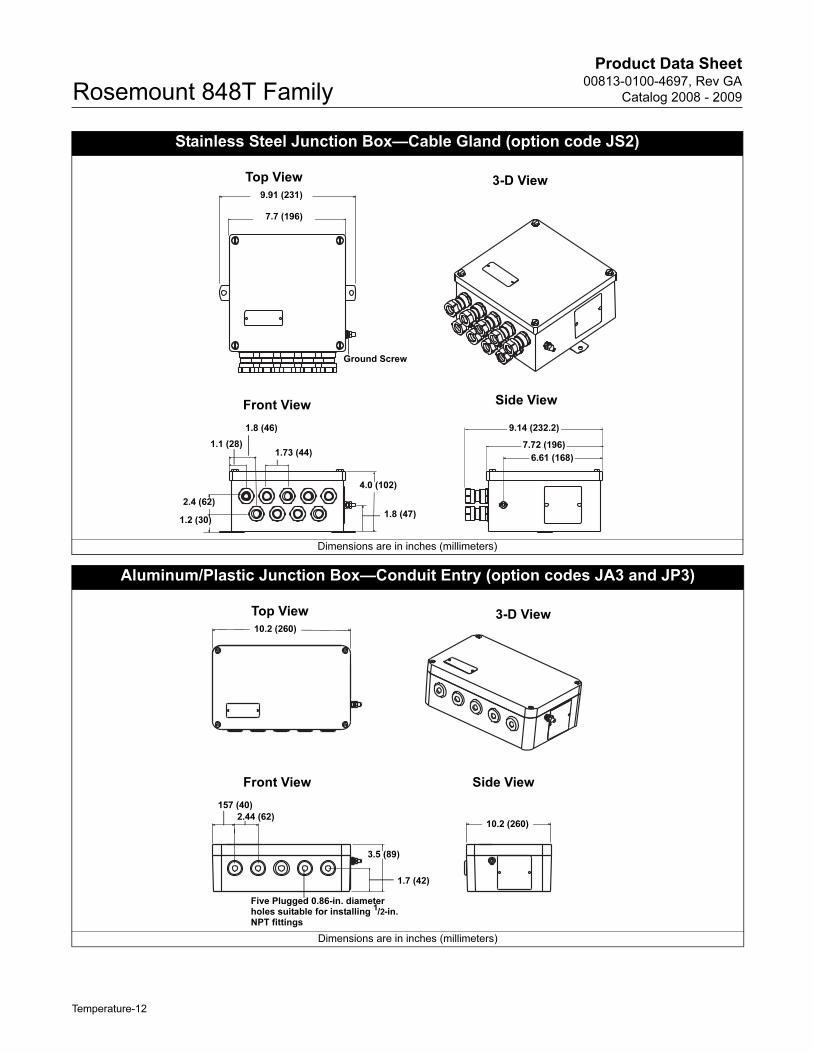
Stainless Steel Junction Box—Cable Gland (option code JS2)
Dimensions are in inches (millimeters)
Aluminum/Plastic Junction Box—Conduit Entry (option codes JA3 and JP3)
Dimensions are in inches (millimeters)
Top View 3-D View
Front View Side View
9.91 (231)
7.7 (196)
4.0 (102)
1.8 (47)1.2 (30)
2.4 (62)
1.1 (28)
1.8 (46)
1.73 (44)6.61 (168)
9.14 (232.2)
Ground Screw
7.72 (196)
Top View 3-D View
Front View Side View
10.2 (260)
157 (40)
2.44 (62)
3.5 (89)
1.7 (42)
10.2 (260)
Five Plugged 0.86-in. diameter holes suitable for installing 1/2-in. NPT fittings
Temperature-12
Product Data Sheet00813-0100-4697, Rev GA
Catalog 2008 - 2009 Rosemount 848T Family
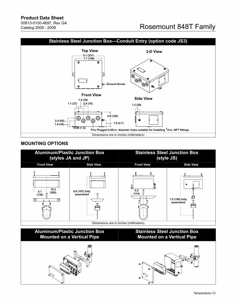
MOUNTING OPTIONS
Stainless Steel Junction Box—Conduit Entry (option code JS3)
Dimensions are in inches (millimeters)
Top View 3-D View
Front ViewSide View
9.1 (231)7.7 (196)
2.8 (70)1.2 (30)
1.4 (35)
1.1 (27)
2.4 (62)
1.6 (42)
0.06 (1.5)
1.8 (4.7)
4.0 (102)
Ground Screw
Five Plugged 0.86-in. diameter holes suitable for installing 1/2-in. NPT fittings
Aluminum/Plastic Junction Box (styles JA and JP)
Stainless Steel Junction Box(style JS)
Front View Side View Front View Side View
Dimensions are in inches (millimeters)
Aluminum/Plastic Junction Box Mounted on a Vertical Pipe
Stainless Steel Junction Box Mounted on a Vertical Pipe
5.1 (130)
10.2 (260) 6.6 (167) fully
assembled
4.5 (114)
7.5 (190) fully assembled
Temperature-13
Product Data Sheet00813-0100-4697, Rev GA
Catalog 2008 - 2009Rosemount 848T Family
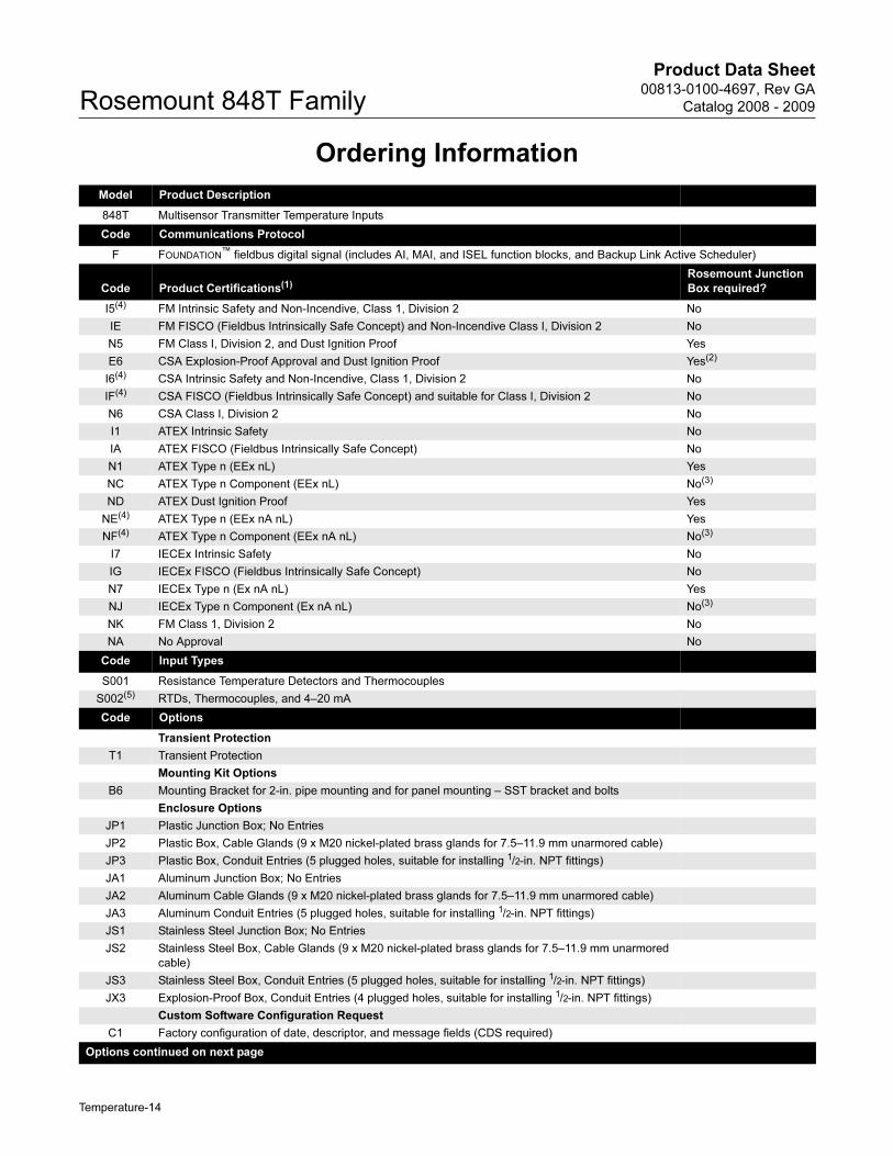
Ordering Information
Model Product Description
848T Multisensor Transmitter Temperature Inputs
Code Communications Protocol
F FOUNDATION™ fieldbus digital signal (includes AI, MAI, and ISEL function blocks, and Backup Link Active Scheduler)
Code Product Certifications(1)Rosemount Junction
Box required?
I5(4) FM Intrinsic Safety and Non-Incendive, Class 1, Division 2 No
IE FM FISCO (Fieldbus Intrinsically Safe Concept) and Non-Incendive Class I, Division 2 No
N5 FM Class I, Division 2, and Dust Ignition Proof Yes
E6 CSA Explosion-Proof Approval and Dust Ignition Proof Yes(2)
I6(4) CSA Intrinsic Safety and Non-Incendive, Class 1, Division 2 No
IF(4) CSA FISCO (Fieldbus Intrinsically Safe Concept) and suitable for Class I, Division 2 No
N6 CSA Class I, Division 2 No
I1 ATEX Intrinsic Safety No
IA ATEX FISCO (Fieldbus Intrinsically Safe Concept) No
N1 ATEX Type n (EEx nL) Yes
NC ATEX Type n Component (EEx nL) No(3)
ND ATEX Dust Ignition Proof Yes
NE(4) ATEX Type n (EEx nA nL) Yes
NF(4) ATEX Type n Component (EEx nA nL) No(3)
I7 IECEx Intrinsic Safety No
IG IECEx FISCO (Fieldbus Intrinsically Safe Concept) No
N7 IECEx Type n (Ex nA nL) Yes
NJ IECEx Type n Component (Ex nA nL) No(3)
NK FM Class 1, Division 2 No
NA No Approval No
Code Input Types
S001 Resistance Temperature Detectors and Thermocouples
S002(5) RTDs, Thermocouples, and 4–20 mA
Code Options
Transient Protection
T1 Transient Protection
Mounting Kit Options
B6 Mounting Bracket for 2-in. pipe mounting and for panel mounting – SST bracket and bolts
Enclosure Options
JP1 Plastic Junction Box; No Entries
JP2 Plastic Box, Cable Glands (9 x M20 nickel-plated brass glands for 7.5–11.9 mm unarmored cable)
JP3 Plastic Box, Conduit Entries (5 plugged holes, suitable for installing 1/2-in. NPT fittings)
JA1 Aluminum Junction Box; No Entries
JA2 Aluminum Cable Glands (9 x M20 nickel-plated brass glands for 7.5–11.9 mm unarmored cable)
JA3 Aluminum Conduit Entries (5 plugged holes, suitable for installing 1/2-in. NPT fittings)
JS1 Stainless Steel Junction Box; No Entries
JS2 Stainless Steel Box, Cable Glands (9 x M20 nickel-plated brass glands for 7.5–11.9 mm unarmored
cable)
JS3 Stainless Steel Box, Conduit Entries (5 plugged holes, suitable for installing 1/2-in. NPT fittings)
JX3 Explosion-Proof Box, Conduit Entries (4 plugged holes, suitable for installing 1/2-in. NPT fittings)
Custom Software Configuration Request
C1 Factory configuration of date, descriptor, and message fields (CDS required)
Options continued on next page
Temperature-14
Product Data Sheet00813-0100-4697, Rev GA
Catalog 2008 - 2009 Rosemount 848T Family
Temperature-15
Transmitter Tag
Hardware
• tagged in accordance with customer requirements
• permanently attached to the transmitter
Software
• the transmitter can store up to 30 characters
• if no characters are specified, the first 30 characters of the
hardware tag will be used
Sensor Tag
Hardware
• a provided plastic tag to record identification of eight sensors
• this information can be printed at the factory upon request
• in the field, the tag can be removed, printed onto, and
reattached to the transmitter
Software
• if sensor tagging is requested, the Sensor Transducer Block
sensor_sn parameters will be set at the factory
• the sensor_sn parameters can be updated in the field
Wiring
Transmitter Configuration
The transmitter is available with the standard configuration setting.
The configuration settings and block configuration may be
changed in the field with the Fisher-Rosemount Systems DeltaV®,
with AMSinside, or other FOUNDATION fieldbus host or
configuration tool.
Standard Configuration
Unless otherwise specified, the transmitter will be shipped as
follows for all eight sensors:
Configuration Options(6)
F5 50 Hz Line Voltage Filter
Calibration Certification
Q4 3 Point Calibration Certificate Provided
Conduit Electrical Connector
GE(7) M12, 4-pin, Male Connector (eurofast®)
GM(7) A size Mini, 4-pin, Male Connector (minifast®)
Typical Model Number: 848T F I5 S001 T1 B6 JA2
(1) Consult factory for availability.
(2) Enclosure Option JX3 must be ordered with Product Certification Code E6.
(3) The Rosemount 848T ordered with component approval is not approved as a stand-alone unit. Additional system certification is required.
(4) Available only with S001 option
(5) S002 is only available with Product Certification N5, N6, N1, NC, Nk, and NA.
(6) Configuration is the same for all eight inputs.
(7) Available with no approval or Intrinsically Safe approvals only. For FM Intrinsically Safe (option code I5), install in accordance with Rosemount drawing 00848-4402.
Model Product Description
Rosemount 848T Sensor Wiring Diagram
* Rosemount provides 4-wire sensors for all single-element
RTDs. Use these RTDs in 3-wire configurations by clipping the
fourth lead or leaving it disconnected and insulated with
electrical tape.
** The transmitter must be configured for a 3-wire RTD in order
to recognize an RTD with a compensation loop.
+ -
1 2 32-wire RTD and Ohms
3-wire RTD and Ohms*
Thermocouples and Millivolts
1 2 3 1 2 32-Wire RTD with
Compensation Loop**
1 2 3
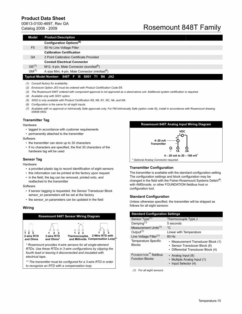
Rosemount 848T Analog Input Wiring Diagram
Standard Configuration Settings
Sensor Type(1)
(1) For all eight sensors
Thermocouple Type J
Damping(1) 5 seconds
Measurement Units(1) °C
Output(1) Linear with Temperature
Line Voltage Filter(1) 60 Hz
Temperature Specific
Blocks• Measurement Transducer Block (1)
• Sensor Transducer Block (8)
• Differential Transducer Block (4)
FOUNDATION™ fieldbus
Function Blocks• Analog Input (8)
• Multiple Analog Input (1)
• Input Selector (4)
4 – 20 mA to 20 – 100 mV*
1A 2A
VDC+ –
+
–
–
4–20 mATransmitter
* Optional Analog Connector required.

Product Data Sheet00813-0100-4697, Rev GA
Catalog 2008 - 2009Rosemount 848T Family
Temperature-16
Coming Soon
The Rosemount 848T Wireless Temperature Transmitter
HIGH DENSITY MEASUREMENT APPLICATIONSIdeal for situations with multiple temperature
measurements within close proximity to each other,
such as distillation colums, tanks, boilers, and heat
exchangers.
SELF-ORGANIZING NETWORKSIntelligent devices that provide exceptional data
reliability and network stability. The Rosemount 848T
Wireless is easy to use, allowing you to leverage
existing practices, training and maintenance
procedures, without adding wiring costs.
LAYERED SECURITY FOR NETWORK SAFETYEmerson Process Management’s layered approach
to wireless network security ensures that your
networks stays protected. The network devices
implement Encryption, Authentication, Verification,
Anti-Jamming and Key Management methods to
ensure data transmissions are received only by the
Wireless Gateway.
CONFIGURABLE ALERTSThe 848T Wireless has four different alert levels
configurable by the user. Alerts can be sent when the
temperature readings rise above or fall below the
user-defined temperature range. Improvements to
product quality or asset performance can be made
with four user configurable alerts.
848T WIRELESS TEMPERATURE TRANSMITTER
SMARTPOWER™Rosemount devices incorporate SmartPower™.
SmartPower™ refers to the benefits that users enjoy
due to the engineering efforts made to reduce power
consumption. Emerson has power-optimized our
instrumentation, both hardware and software, to
extend power module life while still delivering highly
reliable measurements with rich HART data and
diagnostic information.
DIGITAL FIELD DEVICES THAT POWER PLANTWEB
The Rosemount 848T Wireless powers
PlantWeb®
by communicating
temperature diagnostics and PlantWeb
alerts that ensure process health and
enable economical multi-sensor
architecture.
Smart Wireless Solutions
Rosemount 648 Wireless Temperature Transmitter
The 648 integrates temperature measurement into a
self-organizing network to optimize plant performance while
minimizing maintenance.
1420 Wireless Gateway
The 1420 enables the most robust security available, easy host
integration with no additional software, and is continuously
optimizing network performance to maximize data reliability and
power module life of the wireless devices.
Rosemount 3051S Wireless Series
The scaleable 3051S integrates pressure, flow, and level
measurements into a self-organizing network solution to optimize
plant performance and reduce risk.
Rosemount 702 Discrete Input Transmitter
The 702 integrates discrete measurements into a self-organizing
network, and accepts single or dual switch inputs.
Product Data Sheet00813-0100-4697, Rev GA
Catalog 2008 - 2009 Rosemount 848T Family
Specifications
FUNCTIONAL
Inputs
Supports up to 4 thermocouple, 2-, 3-, and 4-wire RTD, mV, ohm,
and 4–20 mA input types.
Outputs
2.4 GHz DSSS WirelessHART, linear with temperature or input.
Humidity Limits
0–100% relative humidity
Transmit Rate
User selectable, 15 seconds to 60 minutes.
Accuracy
PT100 @ reference conditions 20 °C: ±0.30 °C (±0.54 °F).
PHYSICAL
Electrical Connections
Wireless Power Module
Intrinsically Safe, Field Replaceable Lithium-thionyl Chloride
power module. Ten year life at reference conditions.(1)
Sensor Terminals
Screw terminals permanently fixed to the terminal block.
HART Communicator Connections
Communication Terminals
Clips permanently fixed to terminal block.
Materials of Construction
Enclosure
Housing - Low-copper aluminum
Paint - Polyurethane
Cover O-ring - TBD
Mounting
Transmitter can be mounted onto a panel or 2-inch pipe stand.
Sensors must be remotely mounted.
Enclosure Rating
Type 4X; IP65.
(1) Reference conditions are 77 °F (25 °C) and transmit
rate of once every 4 minutes.
Temperature-17
Product Data Sheet00813-0100-4697, Rev GA
Catalog 2008 - 2009Rosemount 848T Family
The Emerson logo is a trademark and service mark of Emerson Electric Co.
Emerson Process Management
© 2008 Rosemount, Inc.
Rosemount and the Rosemount logotype are registered trademarks of Rosemount Inc.HART is a registered trademark of the HART Communication Foundation.FOUNDATION is a trademark of the Fieldbus Foundation.DeltaV is a mark of one of the Emerson Process Management companies.All other marks are the property of their respective owners.
Standard Terms and Conditions of Sale can be found at www.rosemount.com\terms_of_sale
¢00813-0100-4697,¤
Emerson Process Management Asia Pacific Private Limited1 Pandan CrescentSingapore 128461T (65) 6777 8211F (65) 6777 [email protected]
Rosemount Inc.8200 Market BoulevardChanhassen, MN 55317 USAT (U.S.) 1-800-999-9307T (International) (952) 906-8888F (952) 949-7001
www.rosemount.com
Emerson Process ManagementHeath PlaceBognor RegisWest Sussex PO22 9SHEnglandTel 44 (1243) 863 121Fax 44 (1243) 867 554